WO2020095416A1 - Procédé de commande pour véhicule hybride et dispositif de commande pour véhicule hybride - Google Patents
Procédé de commande pour véhicule hybride et dispositif de commande pour véhicule hybride Download PDFInfo
- Publication number
- WO2020095416A1 WO2020095416A1 PCT/JP2018/041521 JP2018041521W WO2020095416A1 WO 2020095416 A1 WO2020095416 A1 WO 2020095416A1 JP 2018041521 W JP2018041521 W JP 2018041521W WO 2020095416 A1 WO2020095416 A1 WO 2020095416A1
- Authority
- WO
- WIPO (PCT)
- Prior art keywords
- engine
- temperature
- gpf
- hybrid vehicle
- motoring
- Prior art date
Links
Images


Classifications
-
- B—PERFORMING OPERATIONS; TRANSPORTING
- B60—VEHICLES IN GENERAL
- B60W—CONJOINT CONTROL OF VEHICLE SUB-UNITS OF DIFFERENT TYPE OR DIFFERENT FUNCTION; CONTROL SYSTEMS SPECIALLY ADAPTED FOR HYBRID VEHICLES; ROAD VEHICLE DRIVE CONTROL SYSTEMS FOR PURPOSES NOT RELATED TO THE CONTROL OF A PARTICULAR SUB-UNIT
- B60W20/00—Control systems specially adapted for hybrid vehicles
- B60W20/10—Controlling the power contribution of each of the prime movers to meet required power demand
- B60W20/15—Control strategies specially adapted for achieving a particular effect
- B60W20/16—Control strategies specially adapted for achieving a particular effect for reducing engine exhaust emissions
-
- B—PERFORMING OPERATIONS; TRANSPORTING
- B60—VEHICLES IN GENERAL
- B60K—ARRANGEMENT OR MOUNTING OF PROPULSION UNITS OR OF TRANSMISSIONS IN VEHICLES; ARRANGEMENT OR MOUNTING OF PLURAL DIVERSE PRIME-MOVERS IN VEHICLES; AUXILIARY DRIVES FOR VEHICLES; INSTRUMENTATION OR DASHBOARDS FOR VEHICLES; ARRANGEMENTS IN CONNECTION WITH COOLING, AIR INTAKE, GAS EXHAUST OR FUEL SUPPLY OF PROPULSION UNITS IN VEHICLES
- B60K6/00—Arrangement or mounting of plural diverse prime-movers for mutual or common propulsion, e.g. hybrid propulsion systems comprising electric motors and internal combustion engines ; Control systems therefor, i.e. systems controlling two or more prime movers, or controlling one of these prime movers and any of the transmission, drive or drive units Informative references: mechanical gearings with secondary electric drive F16H3/72; arrangements for handling mechanical energy structurally associated with the dynamo-electric machine H02K7/00; machines comprising structurally interrelated motor and generator parts H02K51/00; dynamo-electric machines not otherwise provided for in H02K see H02K99/00
- B60K6/20—Arrangement or mounting of plural diverse prime-movers for mutual or common propulsion, e.g. hybrid propulsion systems comprising electric motors and internal combustion engines ; Control systems therefor, i.e. systems controlling two or more prime movers, or controlling one of these prime movers and any of the transmission, drive or drive units Informative references: mechanical gearings with secondary electric drive F16H3/72; arrangements for handling mechanical energy structurally associated with the dynamo-electric machine H02K7/00; machines comprising structurally interrelated motor and generator parts H02K51/00; dynamo-electric machines not otherwise provided for in H02K see H02K99/00 the prime-movers consisting of electric motors and internal combustion engines, e.g. HEVs
- B60K6/42—Arrangement or mounting of plural diverse prime-movers for mutual or common propulsion, e.g. hybrid propulsion systems comprising electric motors and internal combustion engines ; Control systems therefor, i.e. systems controlling two or more prime movers, or controlling one of these prime movers and any of the transmission, drive or drive units Informative references: mechanical gearings with secondary electric drive F16H3/72; arrangements for handling mechanical energy structurally associated with the dynamo-electric machine H02K7/00; machines comprising structurally interrelated motor and generator parts H02K51/00; dynamo-electric machines not otherwise provided for in H02K see H02K99/00 the prime-movers consisting of electric motors and internal combustion engines, e.g. HEVs characterised by the architecture of the hybrid electric vehicle
- B60K6/46—Series type
-
- B—PERFORMING OPERATIONS; TRANSPORTING
- B60—VEHICLES IN GENERAL
- B60W—CONJOINT CONTROL OF VEHICLE SUB-UNITS OF DIFFERENT TYPE OR DIFFERENT FUNCTION; CONTROL SYSTEMS SPECIALLY ADAPTED FOR HYBRID VEHICLES; ROAD VEHICLE DRIVE CONTROL SYSTEMS FOR PURPOSES NOT RELATED TO THE CONTROL OF A PARTICULAR SUB-UNIT
- B60W10/00—Conjoint control of vehicle sub-units of different type or different function
- B60W10/04—Conjoint control of vehicle sub-units of different type or different function including control of propulsion units
- B60W10/06—Conjoint control of vehicle sub-units of different type or different function including control of propulsion units including control of combustion engines
-
- B—PERFORMING OPERATIONS; TRANSPORTING
- B60—VEHICLES IN GENERAL
- B60W—CONJOINT CONTROL OF VEHICLE SUB-UNITS OF DIFFERENT TYPE OR DIFFERENT FUNCTION; CONTROL SYSTEMS SPECIALLY ADAPTED FOR HYBRID VEHICLES; ROAD VEHICLE DRIVE CONTROL SYSTEMS FOR PURPOSES NOT RELATED TO THE CONTROL OF A PARTICULAR SUB-UNIT
- B60W10/00—Conjoint control of vehicle sub-units of different type or different function
- B60W10/04—Conjoint control of vehicle sub-units of different type or different function including control of propulsion units
- B60W10/08—Conjoint control of vehicle sub-units of different type or different function including control of propulsion units including control of electric propulsion units, e.g. motors or generators
-
- B—PERFORMING OPERATIONS; TRANSPORTING
- B60—VEHICLES IN GENERAL
- B60W—CONJOINT CONTROL OF VEHICLE SUB-UNITS OF DIFFERENT TYPE OR DIFFERENT FUNCTION; CONTROL SYSTEMS SPECIALLY ADAPTED FOR HYBRID VEHICLES; ROAD VEHICLE DRIVE CONTROL SYSTEMS FOR PURPOSES NOT RELATED TO THE CONTROL OF A PARTICULAR SUB-UNIT
- B60W10/00—Conjoint control of vehicle sub-units of different type or different function
- B60W10/24—Conjoint control of vehicle sub-units of different type or different function including control of energy storage means
- B60W10/26—Conjoint control of vehicle sub-units of different type or different function including control of energy storage means for electrical energy, e.g. batteries or capacitors
-
- B—PERFORMING OPERATIONS; TRANSPORTING
- B60—VEHICLES IN GENERAL
- B60W—CONJOINT CONTROL OF VEHICLE SUB-UNITS OF DIFFERENT TYPE OR DIFFERENT FUNCTION; CONTROL SYSTEMS SPECIALLY ADAPTED FOR HYBRID VEHICLES; ROAD VEHICLE DRIVE CONTROL SYSTEMS FOR PURPOSES NOT RELATED TO THE CONTROL OF A PARTICULAR SUB-UNIT
- B60W20/00—Control systems specially adapted for hybrid vehicles
- B60W20/10—Controlling the power contribution of each of the prime movers to meet required power demand
- B60W20/13—Controlling the power contribution of each of the prime movers to meet required power demand in order to stay within battery power input or output limits; in order to prevent overcharging or battery depletion
- B60W20/14—Controlling the power contribution of each of the prime movers to meet required power demand in order to stay within battery power input or output limits; in order to prevent overcharging or battery depletion in conjunction with braking regeneration
-
- F—MECHANICAL ENGINEERING; LIGHTING; HEATING; WEAPONS; BLASTING
- F01—MACHINES OR ENGINES IN GENERAL; ENGINE PLANTS IN GENERAL; STEAM ENGINES
- F01N—GAS-FLOW SILENCERS OR EXHAUST APPARATUS FOR MACHINES OR ENGINES IN GENERAL; GAS-FLOW SILENCERS OR EXHAUST APPARATUS FOR INTERNAL COMBUSTION ENGINES
- F01N3/00—Exhaust or silencing apparatus having means for purifying, rendering innocuous, or otherwise treating exhaust
- F01N3/02—Exhaust or silencing apparatus having means for purifying, rendering innocuous, or otherwise treating exhaust for cooling, or for removing solid constituents of, exhaust
- F01N3/021—Exhaust or silencing apparatus having means for purifying, rendering innocuous, or otherwise treating exhaust for cooling, or for removing solid constituents of, exhaust by means of filters
-
- F—MECHANICAL ENGINEERING; LIGHTING; HEATING; WEAPONS; BLASTING
- F02—COMBUSTION ENGINES; HOT-GAS OR COMBUSTION-PRODUCT ENGINE PLANTS
- F02D—CONTROLLING COMBUSTION ENGINES
- F02D45/00—Electrical control not provided for in groups F02D41/00 - F02D43/00
-
- B—PERFORMING OPERATIONS; TRANSPORTING
- B60—VEHICLES IN GENERAL
- B60W—CONJOINT CONTROL OF VEHICLE SUB-UNITS OF DIFFERENT TYPE OR DIFFERENT FUNCTION; CONTROL SYSTEMS SPECIALLY ADAPTED FOR HYBRID VEHICLES; ROAD VEHICLE DRIVE CONTROL SYSTEMS FOR PURPOSES NOT RELATED TO THE CONTROL OF A PARTICULAR SUB-UNIT
- B60W2510/00—Input parameters relating to a particular sub-units
- B60W2510/06—Combustion engines, Gas turbines
- B60W2510/0638—Engine speed
-
- B—PERFORMING OPERATIONS; TRANSPORTING
- B60—VEHICLES IN GENERAL
- B60W—CONJOINT CONTROL OF VEHICLE SUB-UNITS OF DIFFERENT TYPE OR DIFFERENT FUNCTION; CONTROL SYSTEMS SPECIALLY ADAPTED FOR HYBRID VEHICLES; ROAD VEHICLE DRIVE CONTROL SYSTEMS FOR PURPOSES NOT RELATED TO THE CONTROL OF A PARTICULAR SUB-UNIT
- B60W2510/00—Input parameters relating to a particular sub-units
- B60W2510/06—Combustion engines, Gas turbines
- B60W2510/0666—Engine power
-
- B—PERFORMING OPERATIONS; TRANSPORTING
- B60—VEHICLES IN GENERAL
- B60W—CONJOINT CONTROL OF VEHICLE SUB-UNITS OF DIFFERENT TYPE OR DIFFERENT FUNCTION; CONTROL SYSTEMS SPECIALLY ADAPTED FOR HYBRID VEHICLES; ROAD VEHICLE DRIVE CONTROL SYSTEMS FOR PURPOSES NOT RELATED TO THE CONTROL OF A PARTICULAR SUB-UNIT
- B60W2510/00—Input parameters relating to a particular sub-units
- B60W2510/06—Combustion engines, Gas turbines
- B60W2510/068—Engine exhaust temperature
-
- B—PERFORMING OPERATIONS; TRANSPORTING
- B60—VEHICLES IN GENERAL
- B60W—CONJOINT CONTROL OF VEHICLE SUB-UNITS OF DIFFERENT TYPE OR DIFFERENT FUNCTION; CONTROL SYSTEMS SPECIALLY ADAPTED FOR HYBRID VEHICLES; ROAD VEHICLE DRIVE CONTROL SYSTEMS FOR PURPOSES NOT RELATED TO THE CONTROL OF A PARTICULAR SUB-UNIT
- B60W2510/00—Input parameters relating to a particular sub-units
- B60W2510/24—Energy storage means
- B60W2510/242—Energy storage means for electrical energy
- B60W2510/244—Charge state
-
- B—PERFORMING OPERATIONS; TRANSPORTING
- B60—VEHICLES IN GENERAL
- B60W—CONJOINT CONTROL OF VEHICLE SUB-UNITS OF DIFFERENT TYPE OR DIFFERENT FUNCTION; CONTROL SYSTEMS SPECIALLY ADAPTED FOR HYBRID VEHICLES; ROAD VEHICLE DRIVE CONTROL SYSTEMS FOR PURPOSES NOT RELATED TO THE CONTROL OF A PARTICULAR SUB-UNIT
- B60W2520/00—Input parameters relating to overall vehicle dynamics
- B60W2520/10—Longitudinal speed
-
- B—PERFORMING OPERATIONS; TRANSPORTING
- B60—VEHICLES IN GENERAL
- B60W—CONJOINT CONTROL OF VEHICLE SUB-UNITS OF DIFFERENT TYPE OR DIFFERENT FUNCTION; CONTROL SYSTEMS SPECIALLY ADAPTED FOR HYBRID VEHICLES; ROAD VEHICLE DRIVE CONTROL SYSTEMS FOR PURPOSES NOT RELATED TO THE CONTROL OF A PARTICULAR SUB-UNIT
- B60W2530/00—Input parameters relating to vehicle conditions or values, not covered by groups B60W2510/00 or B60W2520/00
- B60W2530/12—Catalyst or filter state
-
- B—PERFORMING OPERATIONS; TRANSPORTING
- B60—VEHICLES IN GENERAL
- B60W—CONJOINT CONTROL OF VEHICLE SUB-UNITS OF DIFFERENT TYPE OR DIFFERENT FUNCTION; CONTROL SYSTEMS SPECIALLY ADAPTED FOR HYBRID VEHICLES; ROAD VEHICLE DRIVE CONTROL SYSTEMS FOR PURPOSES NOT RELATED TO THE CONTROL OF A PARTICULAR SUB-UNIT
- B60W2540/00—Input parameters relating to occupants
- B60W2540/10—Accelerator pedal position
-
- B—PERFORMING OPERATIONS; TRANSPORTING
- B60—VEHICLES IN GENERAL
- B60W—CONJOINT CONTROL OF VEHICLE SUB-UNITS OF DIFFERENT TYPE OR DIFFERENT FUNCTION; CONTROL SYSTEMS SPECIALLY ADAPTED FOR HYBRID VEHICLES; ROAD VEHICLE DRIVE CONTROL SYSTEMS FOR PURPOSES NOT RELATED TO THE CONTROL OF A PARTICULAR SUB-UNIT
- B60W2710/00—Output or target parameters relating to a particular sub-units
- B60W2710/08—Electric propulsion units
- B60W2710/086—Power
-
- Y—GENERAL TAGGING OF NEW TECHNOLOGICAL DEVELOPMENTS; GENERAL TAGGING OF CROSS-SECTIONAL TECHNOLOGIES SPANNING OVER SEVERAL SECTIONS OF THE IPC; TECHNICAL SUBJECTS COVERED BY FORMER USPC CROSS-REFERENCE ART COLLECTIONS [XRACs] AND DIGESTS
- Y02—TECHNOLOGIES OR APPLICATIONS FOR MITIGATION OR ADAPTATION AGAINST CLIMATE CHANGE
- Y02T—CLIMATE CHANGE MITIGATION TECHNOLOGIES RELATED TO TRANSPORTATION
- Y02T10/00—Road transport of goods or passengers
- Y02T10/10—Internal combustion engine [ICE] based vehicles
- Y02T10/40—Engine management systems
-
- Y—GENERAL TAGGING OF NEW TECHNOLOGICAL DEVELOPMENTS; GENERAL TAGGING OF CROSS-SECTIONAL TECHNOLOGIES SPANNING OVER SEVERAL SECTIONS OF THE IPC; TECHNICAL SUBJECTS COVERED BY FORMER USPC CROSS-REFERENCE ART COLLECTIONS [XRACs] AND DIGESTS
- Y02—TECHNOLOGIES OR APPLICATIONS FOR MITIGATION OR ADAPTATION AGAINST CLIMATE CHANGE
- Y02T—CLIMATE CHANGE MITIGATION TECHNOLOGIES RELATED TO TRANSPORTATION
- Y02T10/00—Road transport of goods or passengers
- Y02T10/60—Other road transportation technologies with climate change mitigation effect
- Y02T10/62—Hybrid vehicles
-
- Y—GENERAL TAGGING OF NEW TECHNOLOGICAL DEVELOPMENTS; GENERAL TAGGING OF CROSS-SECTIONAL TECHNOLOGIES SPANNING OVER SEVERAL SECTIONS OF THE IPC; TECHNICAL SUBJECTS COVERED BY FORMER USPC CROSS-REFERENCE ART COLLECTIONS [XRACs] AND DIGESTS
- Y02—TECHNOLOGIES OR APPLICATIONS FOR MITIGATION OR ADAPTATION AGAINST CLIMATE CHANGE
- Y02T—CLIMATE CHANGE MITIGATION TECHNOLOGIES RELATED TO TRANSPORTATION
- Y02T10/00—Road transport of goods or passengers
- Y02T10/60—Other road transportation technologies with climate change mitigation effect
- Y02T10/70—Energy storage systems for electromobility, e.g. batteries
Definitions
- the present invention relates to control of a hybrid vehicle.
- JP2015-202832A and JP2018-83570A disclose hybrid vehicles equipped with a filter that collects particulate matter, that is, PM, in exhaust gas of an engine.
- Some hybrid vehicles have a series hybrid mode in which an engine drives a motor generator for power generation to generate power, and electric power generated by the motor generator for power generation drives the motor generator for running.
- an engine drives a motor generator for power generation to generate power
- electric power generated by the motor generator for power generation drives the motor generator for running.
- PM accumulated on the filter can be burned to regenerate the filter.
- the temperature of the filter may rise excessively as a result of burning PM, and the filter may deteriorate.
- the present invention has been made in view of such problems, and an object thereof is to suppress deterioration of a filter due to excessive temperature rise in a hybrid vehicle having a series hybrid mode.
- a hybrid vehicle control method includes an engine, a power generation motor generator, and a traveling motor generator, and drives the power generation motor generator with the engine to generate power, and uses the power generated by the power generation motor generator.
- a hybrid vehicle control device corresponding to the hybrid vehicle control method.
- FIG. 1 is a schematic configuration diagram of a hybrid vehicle.
- FIG. 2 is a schematic configuration diagram of the exhaust system of the engine.
- FIG. 3 is a diagram illustrating the relationship between the PM deposition amount and the allowable GPF temperature.
- FIG. 4 is an explanatory diagram of engine operation restriction.
- FIG. 5 is a first explanatory diagram of the engine operation limiting method.
- FIG. 6 is a second explanatory diagram of the engine operation limiting method.
- FIG. 7 is a flowchart illustrating an example of control according to the first embodiment.
- FIG. 8 is a diagram showing an example of a timing chart of the first embodiment.
- FIG. 9 is a diagram illustrating the operation mode of the engine.
- FIG. 10 is a flowchart showing an example of control according to the second embodiment.
- FIG. 11 is a diagram showing an example of a timing chart of the second embodiment.
- FIG. 1 is a schematic configuration diagram of a hybrid vehicle 100.
- FIG. 2 is a schematic configuration diagram of the exhaust system 10 of the engine 1.
- a hybrid vehicle 100 includes an engine 1, a power-generating motor generator 2, a traveling motor generator 3, a first inverter 4, a second inverter 5, a battery 6, and a differential mechanism 7. , A drive wheel 8 and a controller 20.
- hybrid vehicle 100 is referred to as vehicle 100, and the motor generator is referred to as MG.
- the engine 1 is a gasoline engine and is connected to the MG 2 for power generation.
- the power generation MG 2 is driven by the engine 1 to generate power.
- the traveling MG 3 is connected to the drive wheels 8 via the differential mechanism 7.
- the traveling MG3 drives the vehicle 100 and regenerates energy during deceleration.
- the power-generating MG2 and the traveling MG3 form a high-voltage voltage circuit 9 together with the first inverter 4, the second inverter 5, the battery 6, and the like.
- the first inverter 4 is used for controlling the MG 2 for power generation
- the second inverter 5 is used for controlling the MG 3 for traveling.
- Each of the first inverter 4 and the second inverter 5 generates a three-phase alternating current based on a command from the controller 20, and applies the generated three-phase alternating current to a corresponding MG of the MG2 for power generation and the MG3 for traveling.
- the first inverter 4 and the second inverter 5 may be integrated.
- the battery 6 constitutes a power source of the MG 2 for power generation and the MG 3 for traveling. Battery 6 is charged with electric power supplied from traveling MG 3 during regeneration. The battery 6 may be charged with the electric power supplied from the MG 2 for power generation.
- the exhaust system 10 includes an exhaust passage 11, a catalytic converter 12, a gasoline particulate filter (hereinafter referred to as GPF) 13, and a muffler 14.
- the exhaust passage 11 circulates the exhaust gas of the engine 1.
- the catalytic converter 12 is provided immediately after the engine 1 and purifies the exhaust gas by oxidizing unburned components such as HC and CO contained in the exhaust gas and reducing oxidized components such as NOx.
- the GPF 13 is provided on the downstream side of the catalytic converter 12 and collects particulate matter, that is, PM in the exhaust gas of the engine 1.
- the GPF 13 may further include a catalyst.
- the muffler 14 is provided downstream of the GPF 13 and reduces exhaust noise.
- the exhaust passage 11 is provided with a differential pressure sensor 21 that detects a differential pressure between the inlet exhaust pressure Pin of the GPF 13 and the outlet exhaust pressure Pout of the GPF 13.
- the PM deposition amount S of the GPF 13 can be estimated based on the pressure difference between the inlet exhaust pressure Pin of the GPF 13 and the outlet exhaust pressure Pout.
- An exhaust gas temperature sensor 23 for detecting the exhaust gas temperature Tex is provided in the exhaust passage 11 connected to the inlet of the GPF 13, and a GPF temperature T, which is the floor temperature of the GPF 13, is provided in the exhaust passage 11 connected to the outlet of the GPF 13.
- a GPF temperature sensor 24 for detecting is further provided.
- the GPF temperature T can be detected as the actual temperature of the temperature of the GPF 13 based on the output signal from the GPF temperature sensor 24.
- the controller 20 is composed of one or a plurality of microcomputers including a central processing unit (CPU), a read only memory (ROM), a random access memory (RAM), and an input / output interface (I / O interface). To be done.
- the controller 20 integrally controls the engine 1, the first inverter 4, the second inverter 5, etc. by executing the program stored in the ROM or the RAM by the CPU.
- the controller 20 includes a first pressure sensor 21, a second pressure sensor 22, an exhaust temperature sensor 23, a GPF temperature sensor 24, a vehicle speed sensor 25 for detecting a vehicle speed VSP, and an accelerator for detecting an accelerator opening APO.
- An opening sensor 26, a brake sensor 27 for detecting the pedal effort BPF of the brake pedal, a rotation speed sensor 28 for detecting the rotation speed Ne of the engine 1, and a battery state quantity SOC indicating the state of charge of the battery 6 are detected. Signals from various sensors and switches such as the SOC sensor 29 for input are input. These signals are used for the control performed by the controller 20.
- the controller 20 has an EV mode and a series hybrid mode (hereinafter referred to as a series HEV mode) as driving modes of the vehicle 100.
- the EV mode is a mode in which the traveling MG3 is driven by the electric power supplied from the battery 6 and traveling is performed by the driving force of only the traveling MG3.
- the series HEV mode is a mode in which the engine 1 drives the power generation MG2 to generate electric power, and the traveling MG3 is driven by the electric power generated by the power generation MG2.
- the controller 20 selects a travel mode based on the accelerator opening APO, the pedal effort BPF of the brake pedal, and the vehicle speed VSP, taking into account a travel mode selection map (not shown), and selects the travel mode to achieve the selected travel mode. And driving MG3 for traveling.
- the PM accumulated in the GPF 13 can be burned to regenerate the GPF 13.
- the present embodiment suppresses the deterioration of the GPF 13 as described below.
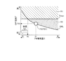
- FIG. 3 is a diagram for explaining the relationship between the PM deposition amount S and the allowable GPF temperature TS.
- the line SML shows the allowable GPF temperature TS according to the PM accumulation amount S.
- the line SML shows the relationship between the PM deposition amount S and the allowable GPF temperature TS.
- the allowable GPF temperature TS is an upper limit value of the GPF temperature T corresponding to the motoring of the engine 1, and the upper limit value of the GPF temperature T at which the GPF 13 does not excessively rise due to the combustion of PM according to the motoring of the engine 1 is PM. It is set according to the deposition amount S. As can be seen from the line SML, the allowable GPF temperature TS decreases as the PM deposition amount S increases.
- the maximum GPF temperature Tmax is the GPF temperature T when the exhaust temperature Tex of the engine 1 is the maximum temperature, and the GPF temperature T usually does not exceed this maximum GPF temperature Tmax. Therefore, the state point PS determined by the PM deposition amount S and the GPF temperature T is not included in the region R1 on the higher temperature side than the maximum GPF temperature Tmax.
- the region R2 which is a region on the higher temperature side than the line SML and does not overlap the region R1, is an avoidance region where the intrusion of the state point PS should be avoided.
- the first predetermined amount SL is the PM accumulation amount S corresponding to the case where the GPF temperature T is the maximum GPF temperature Tmax on the line SML.
- the first predetermined amount SL is the PM deposition amount when the allowable GPF temperature TS is the maximum GPF temperature Tmax, that is, when the allowable GPF temperature TS is the temperature corresponding to the maximum temperature of the exhaust temperature Tex of the engine 1. It is S.
- the PM deposition amount S is equal to or less than the first predetermined amount SL, the GPF temperature T will not exceed the allowable GPF temperature TS. Therefore, when the PM accumulation amount S is less than or equal to the first predetermined amount SL, it is not necessary to limit the operation of the engine 1.
- the allowable GPF temperature TS1 which is the allowable GPF temperature TS corresponding to the accumulation amount S1 is determined based on the line SML.
- the GPF temperature T exceeds the allowable GPF temperature TS1
- the state point PS enters the region R2, and there is a concern that the GPF 13 may deteriorate due to excessive temperature rise during motoring. Therefore, in this embodiment, the operation of the engine 1 is restricted as described below.
- FIG. 4 is an explanatory diagram of the operation restriction of the engine 1.
- an isotherm of the allowable GPF temperature TS1 an isotherm of a temperature Tmp1 lower than the allowable GPF temperature TS1
- the engine 1 starts the power generation operation of driving the MG2 for power generation to generate power.
- the operating point PE of the engine 1 is changed from the operating point PE1 to the operating point PE2.
- the operating point PE1 is the operating point PE when the PM deposition amount S is the deposition amount S1 and the GPF temperature T is the temperature Tmp2, and the operating point PE2 is in the region R3 on the higher temperature side than the isotherm of the allowable GPF temperature TS1. It is the operating point PE.
- the PM accumulated in the GPF 13 rapidly burns due to a high temperature exceeding the allowable GPF temperature TS1, and an excessive temperature rise of, for example, more than 1000 ° C. occurs in the GPF 13, resulting in deterioration of the GPF 13. Is concerned.
- the operating region of the engine 1 is limited to the operating region on the lower temperature side than the region R3.
- the operation of the engine 1 is restricted so that the operating point PE is out of the region R3.
- the operation of the engine 1 is limited based on the allowable GPF temperature TS corresponding to the PM accumulation amount S.
- the operation restriction of the engine 1 can be performed as follows.
- FIG. 5 is a first explanatory diagram of the method for restricting the operation of the engine 1.
- the exhaust gas temperature Tex1 indicates the exhaust gas temperature Tex corresponding to the allowable GPF temperature TS1.
- the two-dot broken line indicates the equal output line of the engine 1.
- FIG. 5 shows a case where the sound and vibration performance of the engine 1 is not considered. Both the exhaust temperature Tex and the output of the engine 1 become higher as the rotational speed Ne and the torque Tq become higher, that is, in the upper right direction in FIG.
- the GPF temperature T be equal to or lower than the allowable GPF temperature TS1. Therefore, the exhaust temperature Tex needs to be suppressed to the exhaust temperature Tex1 at the maximum. On the other hand, when operating the engine 1, it is desired to obtain the highest possible efficiency.
- the upper limit operating point PEmax of the engine 1 is set at a position where the output becomes highest on the isotherm of the exhaust temperature Tex1 and the engine 1 is operated at the rotation speed Ne and the torque Tq that are equal to or lower than the upper limit operating point PEmax, It becomes possible to operate the engine 1 efficiently while restricting the operation.
- the upper limit operating point PEmax1 is the upper limit operating point PEmax set in this way and can be set in advance.
- the upper limit operating point PEmax can be set as follows.
- FIG. 6 is a second explanatory diagram of the operation restriction method of the engine 1.
- the region RNV indicates a region where the sound and vibration performance of the engine 1 does not meet the standard.
- the upper limit operating point PEmax needs to be set while avoiding the region RNV. Therefore, the upper limit operating point PEmax is set to a position where the output is highest on the isotherm of the exhaust temperature Tex1 outside the region RNV.
- the upper limit operating point PEmax2 is the upper limit operating point PEmax set in this way and can be set in advance. In this case, even when operating the engine 1 at the rotation speed Ne and the torque Tq that are equal to or lower than the upper limit operating point PEmax2, the operation of the engine 1 is performed while avoiding the region RNV.
- FIG. 7 is a flowchart showing an example of control performed by the controller 20.
- the controller 20 determines whether the PM accumulation amount S is larger than the first predetermined amount SL. If a negative determination is made in step S11, the process ends once. That is, when the PM deposition amount S is less than or equal to the first predetermined amount SL, the controller 20 does not limit the operation of the engine 1 in step S14 described below. If a positive determination is made in step S11, the process proceeds to step S12.
- step S12 the controller 20 calculates the allowable GPF temperature TS.
- the allowable GPF temperature TS can be calculated by obtaining the allowable GPF temperature TS corresponding to the current PM deposition amount S from the line SML.
- step S13 the controller 20 determines whether the GPF temperature T is higher than the allowable GPF temperature TS. If the GPF temperature T is equal to or lower than the allowable GPF temperature TS, the GPF 13 will not be deteriorated due to excessive temperature rise during motoring of the engine 1. Therefore, if the negative determination is made in step S13, the process is once ended.
- step S13 If the GPF temperature T is higher than the allowable GPF temperature TS, it is feared that the GPF 13 may be deteriorated due to excessive temperature rise during motoring of the engine 1. Therefore, if an affirmative determination is made in step S13, the process proceeds to step S14, and the controller 20 executes the operation restriction of the engine 1.
- the operation limitation of the engine 1 is performed by limiting the operation area of the engine 1.
- step S14 the process ends once.
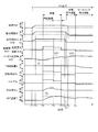
- FIG. 8 is a diagram showing an example of a timing chart corresponding to the flowchart shown in FIG. 7.
- the required driving force starts to increase, and EV traveling in the EV mode is started. Therefore, the vehicle speed VSP and the output of the traveling MG3 start to increase, and the battery state quantity SOC starts to decrease.
- the required driving force becomes constant, the vehicle speed VSP and the output of the traveling MG3 become constant.
- the battery state quantity SOC becomes the charging lower limit value VL of the battery 6. Therefore, the power generation operation of the engine 1 is started, the rotation speed Ne and the torque Tq increase, and the power generation amount of the power generation MG2 increases.
- the exhaust gas temperature Tex and the GPF temperature T also start to rise.
- the GPF temperature T exceeds the allowable GPF temperature TS. Therefore, the operation limitation of the engine 1 is executed, the rotation speed Ne and the torque Tq are reduced, and the power generation amount of the power generation MG2 is reduced.
- the battery state quantity SOC reaches the first charge upper limit value VH1 of the battery 6, and the power generation operation of the engine 1 is stopped.
- the first charge upper limit value VH1 is a charge upper limit value of the battery 6 when the charge regenerative braking described later is not performed.
- the rotation speed Ne, the torque Tq, and the power generation amount of the power generation MG2 become zero in accordance with the stop of the power generation operation, and the battery state amount SOC starts to decrease.
- the power generation operation of the engine 1 is stopped, so that the operation of the engine 1 is not restricted.
- charging regenerative braking that charges the battery 6 with the regenerated electric power while performing the regenerative braking by the traveling MG3 is started.
- Charging regenerative braking is started as follows. That is, when the deceleration of the vehicle 100 is started, the required driving force is first gradually reduced, and accordingly, when the output of the traveling MG3 is gradually reduced to the preset negative regenerative braking output, the charge regenerative braking is performed. Be started. Charging regenerative braking is performed for the following reasons.
- the required driving force becomes zero, and then the preset regenerative braking driving force is reached. From timing T8, the vehicle travels on a downhill road, the required driving force becomes zero or less, and regenerative braking is performed by the traveling MG3, so that the vehicle speed VSP becomes constant.
- the battery state quantity SOC becomes the second charge upper limit value VH2 of the battery 6.
- the second charge upper limit value VH2 is the charge upper limit value of the battery 6 set when performing the charge regenerative braking, and the first charge upper limit value is set in order to make the battery 6 chargeable and to continue the execution of the charge regenerative braking. It is set higher than VH1.
- regenerative braking is performed by the traveling MG3, and motoring regenerative braking is performed in which the regenerative electric power is used to motor the engine 1 by the power generation MG2.
- the traveling MG3 can generate a braking force equivalent to the engine brake.
- the motoring of the engine 1 can be performed as motoring regenerative braking during deceleration.
- the motoring regenerative braking is started, and the power generation MG2 drives the engine 1 by using the electric power regenerated by the traveling MG3. Therefore, the driving force of the power generation MG2 is increased and the rotation speed Ne is To rise.
- the torque Tq becomes a negative torque because the engine 1 is driven by the MG 2 for power generation.
- the GPF temperature T suppressed by the operation restriction performed between timing T4 and timing T5 is below the allowable GPF temperature TS. Therefore, even if the motoring regenerative braking is performed, the GPF 13 does not overheat.
- a series HEV mode that includes the engine 1, the MG 2 for power generation, and the MG 3 for travel, drives the MG 2 for power generation by the engine 1 to generate power, and drives the MG 3 for travel with the electric power generated by the MG 2 for power generation.
- the controller 20 implements the control method of the vehicle 100 that has the GPF 13 that collects PM in the exhaust gas of the engine 1.
- the control method of the vehicle 100 includes restricting the operation of the engine 1 based on the allowable GPF temperature TS corresponding to the PM accumulation amount S in the GPF 13.
- the operation limit of the engine 1 based on the allowable GPF temperature TS makes it possible to suppress the excessive temperature rise of the GPF 13 when burning PM by the motoring of the engine 1. Therefore, according to such a method, in the vehicle 100 having the series HEV mode, it becomes possible to suppress the deterioration of the GPF 13 due to the excessive temperature rise, and when the PM is burned by the motoring, the GPF temperature T It becomes possible to burn PM without considering the above.
- the control method of vehicle 100 further includes not performing the operation limitation when PM deposition amount S is equal to or less than first predetermined amount SL, and first predetermined amount SL includes PM deposition amount S and allowable GPF temperature TS.
- the allowable GPF temperature TS is a temperature corresponding to the maximum temperature of the exhaust gas temperature Tex of the engine 1, that is, the PM deposition amount S corresponding to the maximum GPF temperature Tmax.
- the controller 20 is further configured to perform forced motoring of the engine 1 and temperature increase control of the GPF 13 described below. Except for this point, the vehicle 100 is configured similarly to the case of the first embodiment.
- FIG. 9 is a diagram illustrating an operation mode of the engine 1 according to the PM accumulation amount S and the GPF temperature T.
- the region RM is a region where the forced motoring of the engine 1 in the first operation mode is executed. Forced motoring is motoring that is executed even when charging regenerative braking can be performed, and is performed as forced motoring regenerative braking during deceleration.
- the region RM is a region in which the PM deposition amount S is equal to or higher than the second predetermined amount Sb and the GPF temperature T is equal to or higher than the reproducible temperature TR of the GPF 13 (for example, 550 ° C.) and does not overlap with the regions R1 and R2.
- the second predetermined amount Sb is the PM deposition amount S corresponding to the case where the allowable GPF temperature TS is the maximum GPF temperature Tmax in the line SML, that is, the PM deposition amount S smaller than the first predetermined amount SL.
- the reproducible temperature TR is the lower limit value of the reproducible temperature of the GPF 13.
- the execution area of the forced motoring of the engine 1 is expanded to an area where the PM accumulation amount S is smaller than the first predetermined amount SL and the operation restriction of the engine 1 is unnecessary.
- the chances of burning PM by forced motoring and reducing the PM accumulation amount S increase, so that the state point PS is less likely to enter the region R2.
- the frequency of executing the operation restriction of the engine 1 is reduced.
- the second predetermined amount Sb is the PM deposition amount S that is smaller than the first predetermined amount SL by the predetermined value ⁇ . If the predetermined value ⁇ is too large, the PM deposition amount S is reduced by the forced motoring even if the PM deposition amount S is small, and the efficiency of reducing the PM deposition amount S by the forced motoring becomes poor. When the predetermined value ⁇ is too small, the PM accumulation amount S cannot be sufficiently reduced by the forced motoring, and the execution frequency of the operation restriction of the engine 1 cannot be sufficiently reduced. Therefore, the predetermined value ⁇ is set in advance from the viewpoint of the efficiency of reducing the PM accumulation amount S by the forced motoring and the frequency of executing the operation restriction of the engine 1.
- the area RG is an execution area of the temperature increase control of the GPF 13 which is the second operation mode.
- the temperature rise control of the GPF 13 is performed by changing the operating point PE of the engine 1 during the power generation operation to the operating point PE at which the exhaust temperature Tex becomes high. Therefore, the temperature increase control of the GPF 13 controls at least one of the fuel injection amount, the ignition timing, and the intake air amount of the engine 1 so that at least one of the rotation speed Ne and the torque Tq of the engine 1 during power generation is increased. It can be performed by controlling.
- the region RG is a region where the PM deposition amount S is equal to or higher than the first predetermined amount SL and the GPF temperature T is lower than the regenerable temperature TR, and does not overlap with the region R2. Since the region RG is below the regenerable temperature TR, even if the motoring of the engine 1 is executed, the PM accumulated in the GPF 13 cannot be burned. For this reason, in the region RG, the temperature rise control of the GPF 13 is executed to allow the high-temperature exhaust gas to flow through the GPF 13 to raise the temperature of the GPF 13.
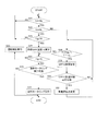
- FIG. 10 is a flowchart showing an example of control performed by the controller 20 in the second embodiment.
- the controller 20 determines in step S21 whether the PM deposition amount S is equal to or more than the second predetermined amount Sb, in step S22 whether the PM deposition amount S is less than or equal to the first predetermined amount SL, and in step S23, the GPF temperature T is a reproducible temperature. It is determined whether or not it is equal to or more than TR. In steps S21 to S23, it is determined whether or not the state point PS is in a region in which the operation restriction of the engine 1 is unnecessary or a region R1 in the region RM that is the execution region of forced motoring.
- step S21 If a negative determination is made in step S21 or step S23, the state point PS is located in a region where the operation mode of the engine 1 is not particularly set. In this case, the process returns to step S21. If a positive determination is made in steps S21 to S23, the process proceeds to step S24.
- step S24 the controller 20 calculates the allowable GPF temperature TS. Further, in step S25, the controller 20 determines whether or not the GPF temperature T is equal to or lower than the allowable GPF temperature TS. If the affirmative determination is made in steps S21 to S23, the state point PS is in the region where the operation restriction is not required, and therefore the GPF temperature T does not exceed the allowable GPF temperature TS. Therefore, in this case, an affirmative decision is made in step S25, and the processing advances to step S26.
- step S26 the controller 20 determines whether forced motoring can be executed. Such a determination can be performed by determining whether or not the conditions for permitting forced motoring are satisfied.
- the conditions for permitting forced motoring include that the engine 1 is not performing a power generation operation and that the battery state quantity SOC is equal to or greater than a predetermined quantity SOC1.
- the predetermined amount SOC1 is a battery state amount SOC required for executing motoring, and can be set in advance. If a positive determination is made in step S26, the process proceeds to step S27.
- step S27 the controller 20 executes forced motoring. As a result, the PM deposited on the GPF 13 burns, and the PM deposition amount S decreases. After step S27, the process ends. Also in the case of a negative determination in step S26, the process ends once.
- step S22 When a negative determination is made in step S22, that is, when the PM deposition amount S is larger than the first predetermined amount SL, the process proceeds to step S29, and the controller 20 determines that the GPF temperature T is less than the reproducible temperature TR and the GPF temperature T is allowable. It is determined whether or not the temperature is equal to or lower than the GPF temperature TS. If a positive determination is made in step S29, the process proceeds to step S30.
- step S30 the controller 20 makes a temperature increase request for the GPF 13.
- the request to raise the temperature of the GPF 13 is a request to execute the temperature rise control of the GPF 13, and is made by turning on a flag, for example.
- step S31 the controller 20 determines whether or not the temperature raising control of the GPF 13 can be executed. Such a determination can be made by determining whether or not the engine 1 is in a power generating operation. When a negative determination is made in step S31, the process returns to step S29. In this case, the process from step S29 to step S31 is repeated until the battery state quantity SOC reaches the charging lower limit value VL of the battery 6 and the power generation operation of the engine 1 is started. If a positive determination is made in step S31, the process proceeds to step S32.
- step S32 the controller 20 changes the power generation operating point, that is, the operating point PE of the engine 1 during the power generating operation, to the operating point PE at which the exhaust temperature Tex becomes high. As a result, the temperature of the GPF 13 can be raised. After step S32, the process returns to step S29.
- step S29 When the temperature of the GPF 13 rises and the GPF temperature T becomes equal to or higher than the regenerable temperature TR, the PM accumulated on the GPF 13 can be combusted by the forced motoring. Therefore, if a negative determination is made in step S29, the process proceeds to step S25 described above, and if a positive determination is made in steps S25 and S26, forced motoring is executed.
- step S25 When the process proceeds to step S25 after the negative determination in step S29, the GPF temperature T may be higher than the allowable GPF temperature TS due to the change of the power generation operating point. In such a case, a negative determination is made in step S25, and the process proceeds to step S28.
- step S28 the controller 20 executes the operation restriction of the engine 1. As a result, the exhaust gas temperature Tex is suppressed and the GPF temperature T is suppressed, so that deterioration of the GPF 13 due to excessive temperature rise during motoring is suppressed. After step S28, the process returns to step S21.
- FIG. 11 is a diagram showing an example of a timing chart corresponding to the flowchart shown in FIG. In the following, mainly, different points from the timing chart shown in FIG. 8 described above will be described in detail.
- timing T1 to timing T3 The change from timing T1 to timing T3 is the same as the timing chart shown in FIG. 8 described above. That is, EV running is started at timing T1, steady running is started at timing T2, and power generation operation of the engine 1 is started at timing T3.
- the GPF temperature T is below the allowable GPF temperature TS. Therefore, the operation restriction of the engine 1 is not started at the timing T4.
- the PM deposition amount S exceeds the second predetermined amount Sb.
- the power generation operation is stopped based on the battery state quantity SOC. Further, deceleration is started at timing T6, and the output of traveling MG3 becomes a negative regenerative braking output at timing T7. Therefore, the charge regenerative braking can be started at the timing T7.
- the PM deposition amount S is smaller than the first predetermined amount SL and larger than the second predetermined amount Sb, and the PM deposition amount S exceeds the first predetermined amount SL. Then, there may be a case where the operation restriction of the engine 1 is necessary.
- the forced motoring regenerative braking is started at timing T7 even if the charging regenerative braking can be performed, and the driving force of the MG2 for power generation is increased due to the forced motoring of the engine 1.
- the rotation speed Ne becomes large and the torque Tq becomes a negative torque.
- the PM deposition amount S starts to decrease.
- the forced motoring regenerative braking can be continued until the PM accumulation amount S becomes smaller than the second predetermined amount Sb by a preset hysteresis amount Sh.
- the PM accumulation amount S is equal to or more than the second predetermined amount Sb
- regenerative braking is performed by the traveling MG3 and the regenerated electric power is used to motor the engine 1 by the power generation MG2.
- the second predetermined amount Sb is set to a PM deposition amount S smaller than the first predetermined amount SL, further including performing forced motoring regenerative braking, which is an example of the motoring regenerative braking.
- the motoring regenerative braking can be performed with the second predetermined amount Sb smaller than the first predetermined amount SL, and the PM accumulation amount S can be reduced. Therefore, it is possible to reduce the frequency with which the operation restriction of the engine 1 is performed due to the PM accumulation amount S that is larger than the first predetermined amount SL, and it is possible to reduce the situation in which the traveling performance is deteriorated due to the operation restriction.
- the method for controlling the vehicle 100 according to the present embodiment further includes performing regenerative braking by the traveling MG 3 and performing charge regenerative braking that charges the battery 6 with the regenerated electric power, and the forced motoring regenerative braking is the charge regenerative braking. Even if you can do it.
- the motoring regenerative braking is forcibly performed while the charge regenerative braking is performed, so that the operation limit of the engine 1 is restricted due to the PM accumulation amount S larger than the first predetermined amount SL.
- the frequency of being exposed can be greatly reduced.
- the forced motoring regenerative braking is further performed when the GPF temperature T is equal to or higher than the reproducible temperature TR.
- the forced motoring regenerative braking is performed in consideration of the GPF temperature T at which the GPF 13 can be regenerated, the fuel consumption is affected by performing the motoring when PM cannot be burned. Can be prevented.
- the control method of the vehicle 100 according to the present embodiment further includes changing the operating point PE of the engine 1 to an operating point PE at which the exhaust temperature Tex becomes high when the GPF temperature T is lower than the regenerable temperature TR.
- the GPF 13 can be quickly heated to make the GPF temperature T equal to or higher than the regenerable temperature TR, and thereby the PM accumulation amount S due to the forced motoring regenerative braking can be quickly reduced. ..
- the forced motoring regenerative braking is further performed when the battery state amount SOC is larger than the predetermined amount SOC1.
- limiting the operation of the engine 1 may include, for example, limiting the operation when the GPF temperature T is equal to or lower than the allowable GPF temperature TS, that is, when the state point PS is not located in the region R2. ..
- Such an operation restriction can be realized by, for example, restricting the operation when the GPF temperature T is higher than the allowable GPF temperature TS by a margin temperature lower by a preset margin.
- Such an operation limitation of the engine 1 is also included in the operation limitation of the engine 1 based on the allowable GPF temperature TS corresponding to the PM accumulation amount S.
- limiting the operation of the engine 1 based on the allowable GPF temperature TS is performed by regenerating the GPF 13 by a method other than motoring, including a known method, such as supplying secondary air to the GPF 13 to regenerate the GPF 13. May be applied when performing.
- a specific numerical value of the allowable GPF temperature TS corresponding to the PM accumulation amount S can be set to a value corresponding to the method of regenerating the GPF 13.
- control method of the vehicle 100 and the control device of the vehicle 100 are realized by the single controller 20 has been described.
- control method of the vehicle 100 and the control device of the vehicle 100 may be implemented by a plurality of controllers, for example.
- the allowable GPF temperature TS may not be used, and the control may be performed only by the PM deposition amount of the GPF 13.
Abstract
L'invention concerne un procédé de commande pour un véhicule hybride, un tel véhicule : comprenant un moteur, un groupe convertisseur destiné à être utilisé en production d'énergie et un groupe convertisseur destiné à être utilisé en déplacement ; ayant un mode hybride en série dans lequel le moteur entraîne le groupe convertisseur destiné à être utilisé en production d'énergie pour produire de l'énergie et l'énergie produite par le groupe convertisseur destiné à être utilisé en production d'énergie entraîne le groupe convertisseur destiné à être utilisé en déplacement ; et comprenant un filtre qui piège des matières particulaires dans l'échappement du moteur. Ce procédé de commande comprend la limitation du fonctionnement du moteur sur la base de la quantité de matières particulaires déposées sur le filtre.
Priority Applications (5)
| Application Number | Priority Date | Filing Date | Title |
|---|---|---|---|
| EP18939128.7A EP3878705B1 (fr) | 2018-11-08 | 2018-11-08 | Procédé de commande pour véhicule hybride et dispositif de commande pour véhicule hybride |
| US17/292,099 US20210402978A1 (en) | 2018-11-08 | 2018-11-08 | Control method of hybrid vehicle and control device of hybrid vehicle |
| PCT/JP2018/041521 WO2020095416A1 (fr) | 2018-11-08 | 2018-11-08 | Procédé de commande pour véhicule hybride et dispositif de commande pour véhicule hybride |
| CN201880098657.2A CN112888609B (zh) | 2018-11-08 | 混合动力车辆的控制方法以及混合动力车辆的控制装置 | |
| JP2020556431A JP7124883B2 (ja) | 2018-11-08 | 2018-11-08 | ハイブリッド車両の制御方法及びハイブリッド車両の制御装置 |
Applications Claiming Priority (1)
| Application Number | Priority Date | Filing Date | Title |
|---|---|---|---|
| PCT/JP2018/041521 WO2020095416A1 (fr) | 2018-11-08 | 2018-11-08 | Procédé de commande pour véhicule hybride et dispositif de commande pour véhicule hybride |
Publications (1)
| Publication Number | Publication Date |
|---|---|
| WO2020095416A1 true WO2020095416A1 (fr) | 2020-05-14 |
Family
ID=70611856
Family Applications (1)
| Application Number | Title | Priority Date | Filing Date |
|---|---|---|---|
| PCT/JP2018/041521 WO2020095416A1 (fr) | 2018-11-08 | 2018-11-08 | Procédé de commande pour véhicule hybride et dispositif de commande pour véhicule hybride |
Country Status (4)
| Country | Link |
|---|---|
| US (1) | US20210402978A1 (fr) |
| EP (1) | EP3878705B1 (fr) |
| JP (1) | JP7124883B2 (fr) |
| WO (1) | WO2020095416A1 (fr) |
Citations (9)
| Publication number | Priority date | Publication date | Assignee | Title |
|---|---|---|---|---|
| JP2002285823A (ja) * | 2001-03-27 | 2002-10-03 | Nissan Motor Co Ltd | 内燃機関の排気浄化装置 |
| JP2010001860A (ja) * | 2008-06-23 | 2010-01-07 | Denso Corp | 内燃機関の排気浄化装置 |
| JP2010242639A (ja) * | 2009-04-07 | 2010-10-28 | Honda Motor Co Ltd | 内燃機関の制御装置 |
| JP2011085092A (ja) * | 2009-10-16 | 2011-04-28 | Mitsubishi Fuso Truck & Bus Corp | シリーズハイブリッド車のdpf再生装置 |
| JP2014227009A (ja) * | 2013-05-21 | 2014-12-08 | いすゞ自動車株式会社 | ハイブリッド車両及びその制御方法 |
| JP2015140150A (ja) * | 2014-01-30 | 2015-08-03 | トヨタ自動車株式会社 | ハイブリッド車両 |
| JP2015202832A (ja) | 2014-04-16 | 2015-11-16 | トヨタ自動車株式会社 | ハイブリッド車両 |
| JP2018083570A (ja) | 2016-11-25 | 2018-05-31 | トヨタ自動車株式会社 | ハイブリッド自動車 |
| JP2018134988A (ja) * | 2017-02-22 | 2018-08-30 | トヨタ自動車株式会社 | ハイブリッド車両の制御装置 |
Family Cites Families (8)
| Publication number | Priority date | Publication date | Assignee | Title |
|---|---|---|---|---|
| DE4321767A1 (de) * | 1993-06-30 | 1995-01-12 | Linde Ag | Verfahren zum Betreiben eines Flurförderzeugs |
| JP4396600B2 (ja) * | 2005-08-23 | 2010-01-13 | 日産自動車株式会社 | ハイブリッド車両の制御装置 |
| US7748214B2 (en) * | 2006-03-03 | 2010-07-06 | Nissan Motor Co., Ltd. | Exhaust gas purification system for hybrid vehicle |
| WO2014042007A1 (fr) * | 2012-09-11 | 2014-03-20 | 本田技研工業株式会社 | Véhicule hybride |
| DE102014220860B4 (de) * | 2014-10-15 | 2018-10-04 | Volkswagen Aktiengesellschaft | Verfahren zum Betreiben eines Hybridfahrzeugs und Hybridfahrzeug |
| JP2017136935A (ja) * | 2016-02-03 | 2017-08-10 | いすゞ自動車株式会社 | ハイブリッド車両及びその制御方法 |
| JP6468298B2 (ja) * | 2017-01-30 | 2019-02-13 | トヨタ自動車株式会社 | ハイブリッド自動車 |
| JP6900929B2 (ja) * | 2018-04-11 | 2021-07-14 | トヨタ自動車株式会社 | 車両 |
-
2018
- 2018-11-08 WO PCT/JP2018/041521 patent/WO2020095416A1/fr unknown
- 2018-11-08 US US17/292,099 patent/US20210402978A1/en active Pending
- 2018-11-08 EP EP18939128.7A patent/EP3878705B1/fr active Active
- 2018-11-08 JP JP2020556431A patent/JP7124883B2/ja active Active
Patent Citations (9)
| Publication number | Priority date | Publication date | Assignee | Title |
|---|---|---|---|---|
| JP2002285823A (ja) * | 2001-03-27 | 2002-10-03 | Nissan Motor Co Ltd | 内燃機関の排気浄化装置 |
| JP2010001860A (ja) * | 2008-06-23 | 2010-01-07 | Denso Corp | 内燃機関の排気浄化装置 |
| JP2010242639A (ja) * | 2009-04-07 | 2010-10-28 | Honda Motor Co Ltd | 内燃機関の制御装置 |
| JP2011085092A (ja) * | 2009-10-16 | 2011-04-28 | Mitsubishi Fuso Truck & Bus Corp | シリーズハイブリッド車のdpf再生装置 |
| JP2014227009A (ja) * | 2013-05-21 | 2014-12-08 | いすゞ自動車株式会社 | ハイブリッド車両及びその制御方法 |
| JP2015140150A (ja) * | 2014-01-30 | 2015-08-03 | トヨタ自動車株式会社 | ハイブリッド車両 |
| JP2015202832A (ja) | 2014-04-16 | 2015-11-16 | トヨタ自動車株式会社 | ハイブリッド車両 |
| JP2018083570A (ja) | 2016-11-25 | 2018-05-31 | トヨタ自動車株式会社 | ハイブリッド自動車 |
| JP2018134988A (ja) * | 2017-02-22 | 2018-08-30 | トヨタ自動車株式会社 | ハイブリッド車両の制御装置 |
Non-Patent Citations (1)
| Title |
|---|
| See also references of EP3878705A4 |
Also Published As
| Publication number | Publication date |
|---|---|
| EP3878705B1 (fr) | 2023-05-03 |
| JPWO2020095416A1 (ja) | 2021-11-25 |
| EP3878705A4 (fr) | 2021-10-20 |
| CN112888609A (zh) | 2021-06-01 |
| JP7124883B2 (ja) | 2022-08-24 |
| US20210402978A1 (en) | 2021-12-30 |
| EP3878705A1 (fr) | 2021-09-15 |
Similar Documents
| Publication | Publication Date | Title |
|---|---|---|
| JP6673139B2 (ja) | ハイブリッド自動車 | |
| CN108223063B (zh) | 混合动力车辆 | |
| CN108437970B (zh) | 混合动力车辆 | |
| KR101773734B1 (ko) | 하이브리드 차량 및 하이브리드 차량용 제어 방법 | |
| JP2018167618A (ja) | 自動車 | |
| JP2015140150A (ja) | ハイブリッド車両 | |
| JP5808997B2 (ja) | ハイブリッド自動車の制御装置 | |
| JP7103169B2 (ja) | ハイブリッド自動車 | |
| KR20170025877A (ko) | 하이브리드 차량의 제어 장치 및 방법 | |
| JP2018062199A (ja) | ハイブリッド自動車 | |
| JP2020083002A (ja) | ハイブリッド自動車 | |
| JP6149510B2 (ja) | ハイブリッド車両及びその制御方法 | |
| JP2008094238A (ja) | ハイブリッド車の制御装置 | |
| JP2020111164A (ja) | ハイブリッド自動車 | |
| JP7124883B2 (ja) | ハイブリッド車両の制御方法及びハイブリッド車両の制御装置 | |
| JP7103171B2 (ja) | ハイブリッド自動車 | |
| CN112888609B (zh) | 混合动力车辆的控制方法以及混合动力车辆的控制装置 | |
| WO2020080063A1 (fr) | Système hybride, dispositif de commande de système hybride et procédé de commande de système hybride | |
| KR20170011367A (ko) | 하이브리드 차량의 제어 장치 및 방법 | |
| JP7087454B2 (ja) | ハイブリッド自動車 | |
| JP2017132299A (ja) | ハイブリッド自動車 | |
| WO2021019618A1 (fr) | Procédé de commande de véhicule hybride et dispositif de commande de véhicule hybride | |
| JP2020131872A (ja) | ハイブリッド自動車 | |
| JP2020082884A (ja) | ハイブリッド自動車 | |
| JP2020142695A (ja) | 車両の制御装置 |
Legal Events
| Date | Code | Title | Description |
|---|---|---|---|
| 121 | Ep: the epo has been informed by wipo that ep was designated in this application |
Ref document number: 18939128 Country of ref document: EP Kind code of ref document: A1 |
|
| ENP | Entry into the national phase |
Ref document number: 2020556431 Country of ref document: JP Kind code of ref document: A |
|
| NENP | Non-entry into the national phase |
Ref country code: DE |
|
| ENP | Entry into the national phase |
Ref document number: 2018939128 Country of ref document: EP Effective date: 20210608 |