WO2020085411A1 - ステアリングコラム装置 - Google Patents
ステアリングコラム装置 Download PDFInfo
- Publication number
- WO2020085411A1 WO2020085411A1 PCT/JP2019/041614 JP2019041614W WO2020085411A1 WO 2020085411 A1 WO2020085411 A1 WO 2020085411A1 JP 2019041614 W JP2019041614 W JP 2019041614W WO 2020085411 A1 WO2020085411 A1 WO 2020085411A1
- Authority
- WO
- WIPO (PCT)
- Prior art keywords
- column
- pair
- portions
- steering
- inner column
- Prior art date
- Legal status (The legal status is an assumption and is not a legal conclusion. Google has not performed a legal analysis and makes no representation as to the accuracy of the status listed.)
- Ceased
Links
Images









Classifications
-
- B—PERFORMING OPERATIONS; TRANSPORTING
- B62—LAND VEHICLES FOR TRAVELLING OTHERWISE THAN ON RAILS
- B62D—MOTOR VEHICLES; TRAILERS
- B62D1/00—Steering controls, i.e. means for initiating a change of direction of the vehicle
- B62D1/02—Steering controls, i.e. means for initiating a change of direction of the vehicle vehicle-mounted
- B62D1/16—Steering columns
- B62D1/18—Steering columns yieldable or adjustable, e.g. tiltable
- B62D1/19—Steering columns yieldable or adjustable, e.g. tiltable incorporating energy-absorbing arrangements, e.g. by being yieldable or collapsible
- B62D1/192—Yieldable or collapsible columns
-
- F—MECHANICAL ENGINEERING; LIGHTING; HEATING; WEAPONS; BLASTING
- F16—ENGINEERING ELEMENTS AND UNITS; GENERAL MEASURES FOR PRODUCING AND MAINTAINING EFFECTIVE FUNCTIONING OF MACHINES OR INSTALLATIONS; THERMAL INSULATION IN GENERAL
- F16F—SPRINGS; SHOCK-ABSORBERS; MEANS FOR DAMPING VIBRATION
- F16F7/00—Vibration-dampers; Shock-absorbers
- F16F7/12—Vibration-dampers; Shock-absorbers using plastic deformation of members
- F16F7/123—Deformation involving a bending action, e.g. strap moving through multiple rollers, folding of members
-
- F—MECHANICAL ENGINEERING; LIGHTING; HEATING; WEAPONS; BLASTING
- F16—ENGINEERING ELEMENTS AND UNITS; GENERAL MEASURES FOR PRODUCING AND MAINTAINING EFFECTIVE FUNCTIONING OF MACHINES OR INSTALLATIONS; THERMAL INSULATION IN GENERAL
- F16F—SPRINGS; SHOCK-ABSORBERS; MEANS FOR DAMPING VIBRATION
- F16F7/00—Vibration-dampers; Shock-absorbers
- F16F7/12—Vibration-dampers; Shock-absorbers using plastic deformation of members
- F16F7/125—Units with a telescopic-like action as one member moves into, or out of a second member
-
- F—MECHANICAL ENGINEERING; LIGHTING; HEATING; WEAPONS; BLASTING
- F16—ENGINEERING ELEMENTS AND UNITS; GENERAL MEASURES FOR PRODUCING AND MAINTAINING EFFECTIVE FUNCTIONING OF MACHINES OR INSTALLATIONS; THERMAL INSULATION IN GENERAL
- F16F—SPRINGS; SHOCK-ABSORBERS; MEANS FOR DAMPING VIBRATION
- F16F7/00—Vibration-dampers; Shock-absorbers
- F16F7/12—Vibration-dampers; Shock-absorbers using plastic deformation of members
- F16F7/128—Vibration-dampers; Shock-absorbers using plastic deformation of members characterised by the members, e.g. a flat strap, yielding through stretching, pulling apart
-
- B—PERFORMING OPERATIONS; TRANSPORTING
- B62—LAND VEHICLES FOR TRAVELLING OTHERWISE THAN ON RAILS
- B62D—MOTOR VEHICLES; TRAILERS
- B62D1/00—Steering controls, i.e. means for initiating a change of direction of the vehicle
- B62D1/02—Steering controls, i.e. means for initiating a change of direction of the vehicle vehicle-mounted
- B62D1/16—Steering columns
- B62D1/18—Steering columns yieldable or adjustable, e.g. tiltable
- B62D1/19—Steering columns yieldable or adjustable, e.g. tiltable incorporating energy-absorbing arrangements, e.g. by being yieldable or collapsible
- B62D1/195—Yieldable supports for the steering column
Definitions
- the present invention relates to a steering column device for rotatably supporting a steering shaft that supports a steering wheel.
- FIG. 18 shows an example of a steering device for an automobile.
- the rotation of the steering wheel 1 is transmitted to the steering gear unit 5 via the steering shaft 2, the universal joint 3, the intermediate shaft 4, etc., and is converted into a linear motion by the steering gear unit 5.
- a steering angle is imparted to the steered wheels 7 by pushing and pulling the left and right tie rods 6 by the linear movement of the steering gear unit 5.
- the steering shaft 2 is rotatably supported with respect to the vehicle body via a steering column device 8.
- WO 2016/114034 discloses a tilt / telescopic mechanism for adjusting the position of a steering wheel and a shock for reducing a shock load applied to a driver's body in the case of a secondary collision.
- a steering column device having an absorption mechanism is described.
- the entire length of the steering shaft is made expandable by combining the steering shaft with the inner shaft and the outer shaft, and the steering column is composed of the rear portion of the front outer column and the rear inner column.
- the front portion so as to be displaceable in the axial direction, the entire length can be expanded and contracted.
- an inner column bracket is joined and fixed to the lower surface of the front portion of the inner column by a shear pin made of synthetic resin.
- the present invention has been made in view of the above circumstances, and an object thereof is to realize a structure of a steering column device in which it is easy to increase the amount of impact load applied to a steering wheel in the event of a secondary collision.
- the steering column device of the present invention includes an inner column, an outer column, a vehicle body side bracket, an adjusting rod, a pair of pressing portions, a scaling mechanism, a telescopic friction plate, a support bracket, and a shock absorbing member.
- the front part of the inner column is fitted inside the rear part of the outer column.
- the outer column has a slit extending in the axial direction, a pair of sandwiched portions arranged at positions sandwiching the slit from both sides in the width direction, and a pair of sandwiched portions penetrating in the width direction. It has a pair of column side through holes.
- the vehicle body side bracket includes a pair of support plate portions that sandwich the pair of sandwiched portions, and a pair of vehicle body side through holes that are formed in portions of the pair of support plate portions that are aligned with each other. .
- the adjustment rod is inserted through the pair of column side through holes and the pair of vehicle body side through holes.
- the pair of pressing portions are arranged in portions of the adjusting rod that project from the outer surfaces of the pair of support plate portions.
- the expansion / contraction mechanism expands / contracts the interval between the pair of pressing portions.
- the telescopic friction plate has a portion between an inner surface of the pair of support plate portions and an outer surface of the pair of clamped portions, and an outer surface of the pair of support plate portions and the pair of pressing members. There is a telescopic elongated hole that is sandwiched by at least one of the portions between the inner side surface of the portion and the inner side surface and through which the adjustment rod is inserted.
- the support bracket is disposed inside the slit, and is attached to the inner column so as to be separably coupled based on an impact load applied to the inner column at the time of a secondary collision, and the telescopic friction. It has a support arm portion that supports the plate and a handle portion that is formed on the surface facing the rear side.
- the impact absorbing member is made of a wire rod, and includes a base portion, a rear end portion of the base portion that is folded back toward the outer side and the front side in the radial direction of the inner column, and the return portion.
- the inner column has an extending portion extending from the outer end portion in the radial direction toward the front side.
- the base portion is attached (fixed or engaged) to the inner column so as to be displaced together with the inner column when the inner column is displaced forward.
- the folded-back portion faces the handle portion.
- the extending portion is restrained from the outside in the radial direction of the inner column so that the extending portion is outside in the radial direction of the inner column. It is preferable to provide a restraining portion that prevents the deformation to one side.
- the restraining portion may include a harness bracket supported and fixed to the support bracket.
- the outer column can be provided with a recessed portion that is open to the front end of the slit and that is recessed radially outward in a portion of the inner peripheral surface that is present on the front side of the slit.
- the recess may have a first guide surface at the rear end that is inclined in a direction in which the depth becomes deeper toward the rear side.
- the recess may have, at the rear end, a second guide surface that is inclined in a direction in which the widthwise dimension increases toward the rear side.
- the folded-back portion includes a pair of folded-back portions
- the extending portion includes a pair of extending portions
- a radial direction of the inner column in each of the pair of folded-back portions It is possible to adopt a configuration in which the ends on the radially inner side of are connected by the base.
- the inner column has cutout portions at two positions spaced apart in the circumferential direction among the front end portions
- the base portion of the shock absorbing member has front end portions of the pair of folded portions.
- a pair of bent portions bent at a right angle from the section, and a connecting portion that connects the ends of the pair of bent portions, and each of the pair of bent portions is engaged with each of the cutout portions.
- a matching configuration can be adopted.
- the rear end portion is an intermediate column in which the rear end portion is fitted to the front end portion of the outer column so as not to be displaced rearward, and the rear end portion is the intermediate portion.
- the front end of the column may include a lower column that is fitted so as to be displaced rearward when a rearward impact load is applied due to a primary collision.
- the amount of impact load applied to the steering wheel at the time of a secondary collision can be made larger than that of the steering column device described in International Publication No. WO 2016/114034. Become.
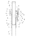
- FIG. 1 is a perspective view of a steering column device according to an example of an embodiment of the present invention as viewed from below and from the rear side.
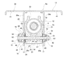
- FIG. 2 is a cross-sectional view showing a portion where the vehicle body side bracket is present in the steering column device shown in FIG.
- FIG. 3 is a cross-sectional view showing a portion of the steering column device shown in FIG. 1 in which an inner column and an outer column are taken out and a rotation preventing mechanism is incorporated.
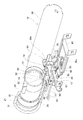
- FIG. 4 is a perspective view of the steering column device shown in FIG. 1 as seen from the front side before a secondary collision occurs by removing some members.
- FIG. 5 is a perspective view of the steering column device shown in FIG.
- FIG. 6 is a perspective view showing a state before a secondary collision occurs in the steering column device shown in FIG. 1 with a part of the members taken out and the outer column being cut.
- FIG. 7 is a perspective view of the steering column device shown in FIG. 1, showing a state after a secondary collision occurs, with a part of the members taken out and the outer column being cut.
- FIG. 8 is a perspective view showing the inner column, the support bracket, the shock absorbing member, and the harness bracket of the steering device shown in FIG.
- FIG. 9 is an exploded perspective view showing the inner column, the support bracket, the shock absorbing member, and the harness bracket of the steering device shown in FIG. FIG.
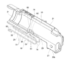
- FIG. 10 is a perspective view showing the support bracket of the steering device shown in FIG.
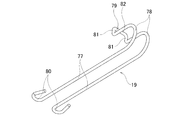
- FIG. 11 is a perspective view showing the shock absorbing member taken out of the steering device shown in FIG.
- FIG. 12 is a perspective view showing the steering device shown in FIG. 1 with the outer column and the impact absorbing member taken out and the outer column cut.
- FIG. 13 is a perspective view of the steering device shown in FIG. 1 when the outer column is taken out and viewed from the front side.
- FIG. 14 is a cross-sectional view showing a state of the steering column device shown in FIG. 1 before some secondary components are taken out and a secondary collision occurs.
- FIG. 15 is a cross-sectional view showing a state immediately after a part of the members of the steering column device shown in FIG. 1 is taken out and a secondary collision occurs.
- FIG. 16 is a cross-sectional view showing a state after a part of the members of the steering column device shown in FIG. 1 is taken out and the secondary collision progresses from the state shown in FIG.
- FIG. 17 (A) is a cross-sectional view showing a state before a secondary collision occurs by taking out one of the joining members that joins the inner column and the support bracket to the steering device shown in FIG. 1.
- FIG. 17B is a cross-sectional view showing a state after the secondary collision of the coupling member occurs.
- FIG. 18 is a perspective view showing an example of a conventional structure of a steering device.
- the steering column device 8a of the present example rotatably supports a steering shaft 2a having a steering wheel 1 (see FIG. 18) supported at its rear end portion with respect to a vehicle body.
- the steering column device 8a of this example includes a tilt / telescopic mechanism for adjusting the vertical position and the front-back position of the steering wheel 1, and an impact for alleviating the impact load applied to the driver's body in the event of a secondary collision. And an absorption mechanism.
- the vertical direction, the front-rear direction, and the width direction are the vertical direction, the front-rear direction, and the width direction when the steering column device 8a is assembled to the vehicle, unless otherwise specified.
- the steering shaft 2a has a structure in which the upper shaft 9 and the lower shaft 10 are combined by spline engagement or the like so that torque can be transmitted and the entire length can be expanded and contracted.
- the steering wheel 1 is supported and fixed to the rear end of the upper shaft 9.
- the key lock collar 11 that constitutes the steering lock device is externally fitted and fixed to the axially intermediate portion of the upper shaft 9.
- the steering column device 8a includes a steering column 12, a vehicle body side bracket 13, an adjusting rod 14, an adjusting lever 15 and a cam device 16 forming an expansion / contraction mechanism, a telescopic friction plate 17, a support bracket 18, and a shock absorbing member. And 19.
- the steering column 12 is configured to be expandable / contractible by fitting the front portion of the rear inner column 20 and the rear portion of the front outer column 21 into each other so as to allow relative displacement in the axial direction.
- the inner column 20 has notches 22 that are open to the front end surface at two locations that are spaced apart in the circumferential direction in the lower portion of the front end portion, and the inner column 20 is separated from the lower surface of the front portion in the axial direction.
- the through holes 23 are provided at the two locations.
- the inner column 20 of this example has a substantially rectangular locking through hole 24 in the rear portion.
- a lock unit (key lock cylinder) (not shown) is supported and fixed to a peripheral portion of the lock through hole 24 on the outer peripheral surface of the inner column 20.
- the lock pin of the lock unit is displaced inward in the radial direction of the steering column 12 through the lock through hole 24, and is formed on the outer peripheral surface of the key lock collar 11.
- the outer column 21 has a slit 25, a pair of clamped portions 26a and 26b, and a pair of column-side through holes 27.
- the slit 25 is for allowing the inner diameter of the rear portion of the outer column 21 to be expanded and contracted, and is formed on the lower surface from the middle portion to the rear portion of the outer column 21 so as to extend in the axial direction.
- the slit 25 has, at the front end, a wide portion 28 having a width dimension larger than that of the portion existing on the rear side.
- the rear end portion of the slit 25 is not opened to the rear end surface of the outer column 21, but it may be opened.
- the slit 25 is formed on the lower surface of the outer column 21, but it is also possible to form the slit on the upper surface of the outer column.
- the pair of sandwiched portions 26a and 26b are arranged at positions sandwiching the rear portion of the slit 25 from both sides in the width direction.
- Each of the pair of column-side through holes 27 is a mere circular hole, and is located at a portion of the pair of sandwiched portions 26a and 26b that are aligned with each other (that is, is coaxial with the pair of sandwiched portions 26a and 26b). ), And each of the pair of clamped portions 26a and 26b is formed so as to penetrate in the width direction.
- the outer column 21 further has a recessed portion 29, of which the rear end portion opens to the front end portion of the slit 25 and which extends in the axial direction, in the portion existing on the front side of the slit 25 on the inner peripheral surface. .
- the recessed portion 29 is inclined toward the rear end in a direction in which the depth dimension in the radial direction becomes deeper toward the rear side, in other words, in the direction in which the thickness dimension of the outer column 21 decreases.
- the concave portion 29 has a second guide surface 88 at the rear end, which is inclined in a direction in which the widthwise dimension becomes wider toward the rear side.
- the front end of the recess 29 is open to the front end surface of the outer column 21.
- the outer column 21 of this example has a fitting holding portion 31 having an inner diameter larger than that of a portion adjacent to the rear side on the inner peripheral surface of the front end portion, and at the rear end of the fitting holding portion 31, It has a step portion 32 facing the front side. Further, the outer column 21 has a rotation stopping slit 33 extending in the axial direction on the upper surface from the front portion to the rear portion. The front and rear end portions of the rotation stopping slit 33 are not open to the front and rear end surfaces of the outer column 21. That is, the detent slit 33 is an elongated hole extending in the axial direction.
- the front portion of the inner column 20 and the rear portion of the outer column 21 are fitted and supported on the upper surface of the inner column 20 as shown in FIG.
- the anti-rotation member 34 is arranged inside the anti-rotation slit 33 so as to be capable of relative displacement in the axial direction without rattling in the width direction. As a result, relative rotation between the inner column 20 and the outer column 21 is prevented. Note that details of the rotation stopping mechanism including the rotation stopping slit 33 and the rotation stopping member 34 are described in detail in International Publication No. WO 2016/114034 and are not related to the gist of the present invention, and therefore will be omitted. Further, if the relative rotation of the inner column 20 and the outer column 21 can be prevented by another means, the detent mechanism can be omitted.
- the steering column 12 of this example further includes an intermediate column 35 and a lower column 36.
- the rear end of the intermediate column 35 is internally fitted and fixed to the fitting holding portion 31 of the outer column 21 by interference fitting with the rear end face of the intermediate column 35 abutting against the step portion 32 of the outer column 21.
- the rear end of the lower column 36 is internally fitted to the front end of the intermediate column 35 so as to allow relative displacement in the axial direction. For this reason, in the steering column 12 of the present example, when a load directed rearward is applied to the lower column 36 due to a primary collision, the lower column 36 is displaced rearward with respect to the intermediate column 35, as will be described later. Is configured.
- the steering column 12 has its front end supported so that it can swing vertically with respect to the vehicle body.
- an annular bush 37 made of an elastic material such as an elastomer such as rubber or a synthetic resin is externally fitted and fixed to the front end of the lower column 36 to form the bush 37 on the vehicle body. It is internally fitted and fixed in the formed coupling hole.
- the front end of the steering column 12 is supported with respect to the vehicle body so as to be swingable in the vertical direction within a range in which the bush 37 can be elastically deformed.
- the steering shaft 2a rotatably supports the rear portion of the upper shaft 9 to the rear end of the inner column 20 via a rolling bearing, and the front portion of the lower shaft 10 to the front end of the lower column 36. And is rotatably supported via another rolling bearing. As a result, the steering shaft 2a is rotatably supported on the inner diameter side of the steering column 12.
- the vehicle body side bracket 13 switches the axial middle portion of the steering column 12 between an unclamped state in which the vertical position and the front-back position of the steering wheel 1 can be adjusted and a clamped state in which the steering wheel 1 is held at the adjusted position. Support as much as possible.
- the vehicle body side bracket 13 has a mounting plate portion 38, a pair of support plate portions 39a and 39b, and a pair of vehicle body side through holes 40.
- the mounting plate portion 38 has a pair of mounting holes 41 on both sides in the width direction.
- the vehicle body side bracket 13 is supported and fixed to the vehicle body so as not to fall off by a bolt inserted through the pair of mounting holes 41.
- the pair of support plate portions 39a and 39b are arranged so as to sandwich the pair of clamped portions 26a and 26b of the outer column 21 from both sides in the width direction.
- the pair of support plate portions 39a and 39b are joined and fixed by welding or the like to the upper end portions of the lower surface of the mounting plate portion 38 at two positions separated in the width direction. That is, the pair of support plate portions 39 a and 39 b hang downward from two positions on the lower surface of the mounting plate portion 38 that are separated in the width direction.
- the pair of vehicle body-side through holes 40 are formed in portions of the pair of support plate portions 39a and 39b that are aligned with each other.
- each of the vehicle body side through holes 40 is an elongated hole extending in the vertical direction. More specifically, each of the vehicle body side through holes 40 extends in an arc direction centered on the swing center in the vertical direction of the steering column 12.
- the adjusting rod 14 has a pair of column side through holes 27 and a pair of vehicle body side through holes 40 inserted in the width direction.
- the adjustment rod 14 has a head portion 42 at one end (left side in FIG. 2) in the axial direction of the adjustment rod 14, and a male screw at the other end (right side in FIG. 2) in the axial direction of the adjustment rod 14. It has a part 43.
- one of the pair of support plate portions 39a, 39b (left side in FIG. 2), a portion protruding from the outer surface of the support plate portion 39a has a width
- the adjustment lever 15 and the cam device 16 are arranged in this order from the outside in the direction. In other words, the adjustment lever 15 and the cam device 16 are arranged between the head portion 42 and the outer surface of the support plate portion 39a.
- the cam device 16 includes a driven side cam 44 arranged on the inner side in the width direction and a driving side cam 45 arranged on the outer side in the width direction.
- the driven cam 44 is made of sintered metal, has a driven cam surface 46 that is an uneven surface in the circumferential direction on the outer surface in the width direction of the vehicle body, and projects inward in the width direction on the inner surface.
- the engaging protrusion 47 has a substantially rectangular shape.
- the driven cam 44 is externally fitted to the adjusting rod 14 so as to be capable of relative rotation with respect to the adjusting rod 14 and relative displacement in the axial direction of the adjusting rod 14.
- the driven side cam 44 engages the engaging convex portion 47 with the vehicle body side through hole 40 formed in the one support plate portion 39a so that only the displacement along the vehicle body side through hole 40 is possible. There is.
- the drive-side cam 45 is made of sintered metal and has a drive-side cam surface 48 that is an uneven surface in the circumferential direction on the inner side surface in the width direction of the vehicle body.
- the drive side cam 45 is fixed to the base of the adjusting lever 15, and reciprocally rotates as the adjusting lever 15 reciprocates.
- the fitting convex portion 49 formed on the outer side surface of the drive side cam 45 in the width direction of the vehicle body and the fitting hole 50 formed in the base portion of the adjustment lever 15 are non-circularly fitted.
- the base portion of the adjusting lever 15 and the driving side cam 45 may be externally fitted to the adjusting rod 14 so as to rotate integrally with the adjusting rod 14, or may be fitted to the adjusting rod 14 so as to be rotatable relative thereto. You can also
- a portion outside the outer surface of the support plate portion 39b of the other (right side in FIG. 2) of the pair of support plate portions 39a, 39b is surrounded by a width direction outer side.
- the nut 51 and the thrust bearing 52 are arranged in this order from.
- the nut 51 is screwed onto the male screw portion 43 of the adjusting rod 14.
- the adjustment lever 15 is swung to expand or contract the axial dimension of the cam device 16, that is, the dimension in the width direction of the vehicle body.
- the interval between the pair of support plate portions 39a, 39b can be expanded / contracted. That is, in this example, the driven cam 44 and the thrust bearing 52 of the cam device 16 are a pair of pressing portions, and the adjusting lever 15 and the cam device 16 constitute an expansion / contraction device.
- the telescopic friction plate 17 is arranged to increase the holding force of the steering column 12 with respect to the vehicle body side bracket 13.
- a friction plate unit 54 which is formed by sandwiching one fixed-side friction plate 53 between a pair of telescopic friction plates 17, is provided with a pair of sandwiched portions 26a and 26b in the width direction outer surface.
- the holding force of the steering column 12 is further increased by arranging the supporting plates 39a and 39b at the portions between the inner surfaces in the width direction, respectively.
- Each of the telescopic friction plates 17 is made of a metal plate such as a steel plate having a large friction coefficient with respect to the widthwise inner side surfaces of the support plate portions 39a and 39b and the widthwise outer side surfaces of the sandwiched portions 26a and 26b. It is a rectangle.
- Each of the telescopic friction plates 17 has a telescopic elongated hole 55 extending in the axial direction of the steering column 12 in the range from the intermediate portion to the rear portion, and has a substantially rectangular support hole 56 in the front portion.
- the adjusting rod 14 is inserted into the telescopic elongated hole 55, and the front portion is supported by the inner column 20 via the support bracket 18.
- Each of the fixed-side friction plates 53 is made of a metal plate such as a steel plate having a large friction coefficient with respect to the side surface of the telescopic friction plate 17, and has a circular hole 87 for inserting the adjusting rod 14.
- the fixed-side friction plate 53 connects the central portions of the lower ends thereof with a connecting plate portion 57.
- the connecting plate portion 57 is arranged below the pair of held portions 26a and 26b.
- the fixed-side friction plate 53 is displaced in synchronization with the adjustment rod 14 when adjusting the vertical position or the front-back position of the steering wheel 1. That is, the fixed-side friction plate 53 is displaced in the vertical direction together with the adjusting rod 14 when adjusting the vertical position of the steering wheel 1, and remains at that position when adjusting the front-back position of the steering wheel 1. .
- the support bracket 18 is supported on the lower surface of the inner column 20 so as to be separable based on the impact load applied to the inner column 20 during a secondary collision. Further, the support bracket 18 supports the telescopic friction plate 17 so that the telescopic friction plate 17 can be displaced in the width direction.
- the support bracket 18 includes a bracket base portion 58, a mounting portion 59, a pair of support arm portions 60 a and 60 b, and a pair of handle portions 61.
- the bracket base portion 58 has a rectangular column shape, and has a cylindrical boss portion 62 at the center of the lower surface.
- the mounting portion 59 has a rectangular plate shape, and extends rearward from an upper end of the rear end surface of the bracket base 58.
- the mounting portion 59 has through holes 63 at two positions separated from each other in the axial direction.
- the support arm portions 60a and 60b extend in the width direction from both side surfaces in the width direction of the bracket base portion 58, and the support protrusions 64 on the width direction outer side with respect to the base end portion 65 on the width direction inner side as viewed in the front-rear direction. It has a crank-shaped side surface that is offset to the upper side.
- the support protrusion 64 has a rectangular column shape.
- the support protrusions 64 are inserted into the support holes 56 of the telescopic friction plates 17 constituting the friction plate units 54 so that the support protrusions 64 can be displaced in the width direction without rattling in the front-rear direction.
- each of the telescopic friction plates 17 is supported by the support bracket 18 so as to be displaceable in the width direction.
- Each of the base end portions 65 has a concave groove 66 formed so as to be continuous with the lower surface and the rear side surface of the end portion on the inner side in the width direction, and a portion of the bottom surface of the concave groove 66 facing the rear side (
- the handle portion 61 is provided on a portion formed on the rear side surface of the base end portion 65).
- each of the handling parts 61 is a partial cylindrical surface.
- the handling portion 61 may be a composite surface formed by combining a plurality of curved surfaces and / or flat surfaces.
- one of the support arm portions 60 a and 60 b has a screw hole 67 on the lower surface of the base end portion 65 of one support arm portion 60 a.
- the support bracket 18 is separably supported on the lower surface of the inner column 20 by the connecting member 68 based on the impact load applied to the inner column 20 in the case of a secondary collision.
- Each of the coupling members 68 includes an outer pin 69 and an inner pin 70, which are made of synthetic resin.
- the outer pin 69 is formed into a tubular shape as a whole, and includes a cylindrical portion 71 and a base end portion (lower end portion in FIG. 17A) outer peripheral surface of the cylindrical portion 71.
- An outward flange portion 72 that projects outward in the radial direction and a slot portion 73 that is disposed adjacent to the tip end side of the cylindrical portion 71 (upper side in FIG. 17A) are provided.
- the slot portion 73 has slits open at the end face on the tip side at two positions on the radially opposite side. Further, the slot portion 73 has a substantially triangular generatrix shape. That is, the outer diameter dimension of the slot portion 73 is larger than the outer diameter dimension of the cylindrical portion 71. On the other hand, the inner diameter dimension of the slot portion 73 is equal to the inner diameter dimension of the cylindrical portion 71.
- the inner pin 70 has a shaft portion 75 and a head portion 76 formed at the base end portion of the shaft portion 75.
- the front portion of the inner column 20 and the rear portion of the outer column 21 are fitted so as to be capable of relative displacement in the axial direction, and the detent member 34 is provided. Is arranged inside the rotation stopping slit 33. In this state, the through hole 23 of the inner column 20 exists inside the slit 25 of the outer column 21. Next, the through hole 63 of the support bracket 18 and the through hole 23 of the inner column 20 are aligned. That is, the axial position of the support bracket 18 with respect to the inner column 20 is adjusted so that the through hole 63 and the through hole 23 are coaxial.
- the slotted portion 73 of the outer pin 69 is elastically contracted from below into the through hole 63 of the support bracket 18 and the through hole 23 of the inner column 20, and then restored.
- the cylindrical portion 71 of the outer pin 69 is arranged inside the through hole 63 and the through hole 23, and the mounting portion 59 of the support bracket 18 and the inner column 20 are disposed between the outward flange portion 72 and the slit portion 73.
- the coupling member 68 is sheared and the inner column 20 and the support bracket 18 are separated.
- the shaft portion 75 of the inner pin 70 is press-fitted inside the outer pin 69 in the radial direction to prevent the slit portion 73 of the outer pin 69 from shrinking.
- the support bracket 18 is separably supported on the lower surface of the inner column 20 based on the forward-directed impact load applied to the inner column 20 during a secondary collision.
- the synthetic resin is injected into the through holes 63 and the through holes 23 (injection molding), or a synthetic resin or light alloy element pin molded in a cylindrical shape in advance is used as the through holes 63 and the through holes 23. It is also possible to support the support bracket 18 against the lower surface of the inner column 20 by press-fitting into the inner bracket 20.
- the shock absorbing member 19 is formed by bending a wire made of a metal such as mild steel, and has a pair of extending portions 77 extending in the axial direction and a pair of extending portions 77 on the rear side of the extending portions 77. It is provided with a pair of folded-back portions 78 that are bent in a U-shape about 180 degrees from the end portions toward the upper side and the front side, and a base portion 79 that connects the front-side end portions of the pair of folded-back portions 78.
- each of the extending portions 77 is provided with a curved portion 80 that is bent in a substantially U shape from the front end toward the outer side in the width direction and rearward by more than 180 degrees.
- the base portion 79 has a pair of bent portions 81 bent upward from the front end portions of the pair of folded portions 78 at right angles and upper end portions of the pair of bent portions 81. And a connecting portion 82 for connecting.
- the shock absorbing member 19 is bridged between the inner column 20 and the support bracket 18, which are portions that are axially displaced relative to each other in the case of a secondary collision. Specifically, the shock absorbing member 19 engages each of the pair of bent portions 81 with each of the cutout portions 22 of the inner column 20, and at the same time, the inner peripheral surface (front side surface) of the pair of folded portions 78. Are opposed to the handle portion 61 of the support bracket 18. Further, the rear side portions of the pair of extending portions 77 are arranged inside the concave portion 66 of the support bracket 18 that faces downward (the portion formed on the lower surface of the base end portion 65). .
- a pair of bent portions 81 are formed in a state where the shock absorbing member 19 is bridged between the inner column 20 and the support bracket 18 (before the secondary collision occurs).
- a gap is provided between the cutout portion 22 and the rear end portion of the cutout portion 22 and between the pair of folded portions 78 and the handling portion 61.
- the length dimension of the gap between the pair of bent portions 81 and the rear end portion of the cutout portion 22 is set to be between the pair of folded portions 78 and the handling portion 61. It is smaller than the length of the gap in the part.
- the length dimension of the gap between the pair of bent portions 81 and the rear end portion of the cutout portion 22, and the pair of folded portions 78 and the handle portion 61 is made. It is possible to make the total sum of the length dimension of the gap in the portion between and 3 mm or more and 15 mm or less, preferably 6 mm or more and 10 mm or less.
- the steering column device 8a of this example further includes a harness bracket 83 for supporting the wire harness.
- the harness bracket 83 is formed by stamping and bending a metal plate such as a steel plate with a press.
- the harness bracket 83 has an oval receiving hole 84 extending in the width direction at the center in the width direction of the front side portion, and has a circular hole 85 in the width direction one side portion of the front side portion.
- the harness bracket 83 engages the receiving hole 84 with the boss portion 62 of the support bracket 18 (inserts the boss portion 62 into the receiving hole 84) and inserts the screw 86 inserted through the circular hole 85 into the screw hole of the support bracket 18. It is supported and fixed to the support bracket 18 by being screwed onto 67 and further tightened. As a result, when the shock absorbing member 19 is plastically deformed due to the secondary collision, the harness bracket 83 is located behind the pair of extending portions 77 arranged inside the concave groove 66 of the support bracket 18 by the upper surface. By suppressing the side portion from the lower side, the extending portion 77 is prevented from being deformed so as to swing downward. That is, in this example, the harness bracket 83 has a function as a restraining portion.
- the vertical position of the steering wheel 1 can be adjusted within a range in which the adjusting rod 14 can move inside the vehicle body side through hole 40 of the vehicle body side bracket 13, and the adjusting rod 14 can be adjusted to a telescopic position.
- the front-back position of the steering wheel 1 can be adjusted within a range where the friction plate 17 can move inside the telescopic elongated hole 55.
- the drive side cam 45 is rotated in the locking direction by swinging the adjusting lever 15 in the direction opposite to the predetermined direction (for example, upward).
- the tip end surface of the convex portion of the driving side cam surface 48 and the tip end surface of the convex portion of the driven side cam surface 46 abut against each other, thereby expanding the axial dimension of the cam device 16 and driving the driven side cam 44.
- the thrust bearing 52 is shortened.
- the contact pressure between the inner side surfaces of the support plate portions 39a and 39b and the outer side surfaces of the sandwiched portions 26a and 26b increases, and at the same time, the inner diameter of the rear portion of the outer column 21 elastically contracts.
- the surface pressure of the contact portion between the inner peripheral surface of the rear portion of the outer column 21 and the outer peripheral surface of the front portion of the inner column 20 increases.
- the steering wheel 1 is held at the adjusted position.
- the lower column 36 which is rotatably supported via rolling bearings, is relatively displaced rearward with respect to the intermediate column 35 so as to reduce the overall length of the steering column 12.
- the steering wheel 1 is prevented from being displaced so as to be pushed up rearward.
- a secondary collision may occur in which the driver's body collides with the steering wheel 1.
- a frontward impact load is applied from the steering wheel 1 to the inner column 20 via the upper shaft 9.
- a forward impact load is applied to the inner column 20
- the inner column 20 tries to be displaced forward with respect to the vehicle body with respect to the vehicle body side bracket 13 and the support bracket 18 supported by the telescopic friction plate 17.
- a shearing force is generated between the inner column 20 and the support bracket 18, and the joining member 68 is sheared by this shearing force.
- forward displacement of the inner column 20 the upper shaft 9 and the steering wheel 1 supported by the inner column 20 is allowed, and the impact load applied to the driver's body is reduced.
- the shock absorbing member 19 spanned between the inner column 20 and the support bracket 18 is plastically deformed. That is, when the inner column 20 is displaced forward and the base portion 79 of the shock absorbing member 19 is pulled forward, the pair of folded-back portions 78 of the shock absorbing member 19 are pressed against the handle portion 61 of the support bracket 18. From this state, when the inner column 20 is further displaced forward, the portion that was the folded-back portion 78 is handled by the handling portion 61 and moves forward (to the straight line portion that connects the folded-back portion 78 and the base 79).
- the portion that was the extending portion 77 is fed into the portion that is handled by the handling portion 61 and is curved to become the folded-back portion 78.
- the inner column 20 is configured to be displaced forward while plastically deforming the shock absorbing member 19, so that the shock load applied to the body of the driver who collides with the steering wheel 1 is further increased. Can be relaxed.
- the coupling member 68 is sheared, and the inner column 20 starts to move forward, the impact absorbing member 19 is plastically deformed to start absorbing the impact load.
- the idling section where the shock absorbing member 19 cannot be plastically deformed is substantially (a pair of the bent portion 81 and the notch portion 22 It is possible to eliminate the idle running portion based on the gap existing between the end portion and the portion between the pair of folded-back portions 78 and the handle portion 61).
- the concave portion 29 has a second guide surface 88 at the rear end, which is inclined in a direction in which the widthwise dimension becomes wider toward the rear side.
- the portion of the shock absorbing member 19 that connects the lower end of the pair of bent portions 81 of the base 79 and the upper end of the pair of folded portions 78 is defined by the handle portion 61. Even when it is deformed so as to expand in the width direction when it is handled, it can be guided to the inside of the recess 29 by the second guide surface 88.
- the steering column device 8a of this example is configured such that the inner column 20 is displaced forward due to the impact load at the time of the secondary collision, but does not fall off even when the secondary collision progresses. Therefore, even when the secondary collision progresses, the steering wheel 1 can be prevented from being excessively displaced downward, and, for example, when the accident vehicle is capable of self-propelled, the accident vehicle can be driven from the accident site to the road shoulder. This makes it easier to drive when moving.
- the steering column device 8a of this example includes a shock absorbing member 19 that absorbs a shock load caused by a secondary collision by plastically deforming due to the forward displacement of the inner column 20 in the case of a secondary collision. Therefore, according to the steering column device 8a of this example, the amount of absorption of the impact load applied to the steering wheel 1 at the time of a secondary collision is compared with that of the steering column device described in International Publication No. 2016/114034. Can be made larger.
- the support bracket 18 is supported at a central position in the width direction on the lower surface of the inner column 20, and the shock absorbing member 19 is arranged so as to span the support bracket 18 and the inner column 20. That is, since the shock absorbing member 19 can be arranged at the center position in the width direction of the inner column 20, the posture of the shock absorbing member 19 at the time of the secondary collision can be stabilized, and the shock absorbing member 19 is plastically deformed. It is easy to stabilize the shock absorption performance.
- the impact absorbing member 19 is extended between the inner column 20 and the support bracket 18 (the state before the secondary collision occurs), and the pair of bent portions 81 and the notch portion 22 are deep inside.
- a gap is made to exist between the end portion and the pair of folded-back portions 78 and the handle portion 61. Therefore, even after the support bracket 18 is coupled to the inner column 20, the shock absorbing member 19 can be easily assembled between the inner column 20 and the support bracket 18.
- the length dimension of the gap between the pair of bent portions 81 and the rear end portion of the cutout portion 22 is set to the pair of folded portions 78 and the handle portion 61. It is smaller than the length of the gap in the space. Therefore, it is possible to prevent the shock absorbing member 19 from falling off from the inner column 20 from the state in which the shock absorbing member 19 is bridged between the inner column 20 and the support bracket 18.
- the plastic deformation of the shock absorbing member 19 can be started after the coupling member 68 is surely sheared. As a result, it is possible to suppress variations in the shock absorbing characteristics due to the plastic deformation of the shock absorbing member 19.
- the outer column 21 has a front end of a recess 29 formed in a portion of the inner peripheral surface existing on the front side of the slit 25, which is open to the front end surface of the outer column 21. Therefore, even if the outer column 21 is manufactured by casting, the mold can be pulled out without difficulty. Further, since the rigidity in the radial direction of the fitting holding portion 31 formed on the inner peripheral surface of the front end of the outer column 21 can be appropriately reduced, the fitting holding portion 31 is provided with a rear side of the intermediate column 35. The press-fitting load at the time of press-fitting the ends of the can be suppressed and stabilized.
Landscapes
- Engineering & Computer Science (AREA)
- General Engineering & Computer Science (AREA)
- Mechanical Engineering (AREA)
- Chemical & Material Sciences (AREA)
- Combustion & Propulsion (AREA)
- Transportation (AREA)
- Steering Controls (AREA)
Priority Applications (4)
| Application Number | Priority Date | Filing Date | Title |
|---|---|---|---|
| JP2020552578A JP7310828B2 (ja) | 2018-10-24 | 2019-10-24 | ステアリングコラム装置 |
| DE112019005339.6T DE112019005339T5 (de) | 2018-10-24 | 2019-10-24 | Lenksäulenvorrichtung |
| CN201980069995.8A CN112930296B (zh) | 2018-10-24 | 2019-10-24 | 转向柱装置 |
| US17/287,223 US11427244B2 (en) | 2018-10-24 | 2019-10-24 | Steering column device |
Applications Claiming Priority (2)
| Application Number | Priority Date | Filing Date | Title |
|---|---|---|---|
| JP2018-200403 | 2018-10-24 | ||
| JP2018200403 | 2018-10-24 |
Publications (1)
| Publication Number | Publication Date |
|---|---|
| WO2020085411A1 true WO2020085411A1 (ja) | 2020-04-30 |
Family
ID=70331061
Family Applications (1)
| Application Number | Title | Priority Date | Filing Date |
|---|---|---|---|
| PCT/JP2019/041614 Ceased WO2020085411A1 (ja) | 2018-10-24 | 2019-10-24 | ステアリングコラム装置 |
Country Status (5)
| Country | Link |
|---|---|
| US (1) | US11427244B2 (https=) |
| JP (1) | JP7310828B2 (https=) |
| CN (1) | CN112930296B (https=) |
| DE (1) | DE112019005339T5 (https=) |
| WO (1) | WO2020085411A1 (https=) |
Cited By (2)
| Publication number | Priority date | Publication date | Assignee | Title |
|---|---|---|---|---|
| WO2022138158A1 (ja) * | 2020-12-24 | 2022-06-30 | 日本精工株式会社 | ステアリングコラム装置 |
| WO2023228447A1 (ja) * | 2022-05-23 | 2023-11-30 | 日本精工株式会社 | ステアリング装置 |
Families Citing this family (2)
| Publication number | Priority date | Publication date | Assignee | Title |
|---|---|---|---|---|
| US11440579B2 (en) * | 2018-11-16 | 2022-09-13 | Nsk Ltd. | Steering column device |
| CN113371054B (zh) * | 2021-07-30 | 2022-10-04 | 北京长安汽车工程技术研究有限责任公司 | 一种转向管柱总成及车辆 |
Citations (4)
| Publication number | Priority date | Publication date | Assignee | Title |
|---|---|---|---|---|
| US20090218801A1 (en) * | 2008-02-29 | 2009-09-03 | Mando Corporation | Collision energy absorbable steering column for vehicle |
| WO2016114034A1 (ja) * | 2015-01-13 | 2016-07-21 | 日本精工株式会社 | ステアリング装置 |
| JP2017081214A (ja) * | 2015-10-23 | 2017-05-18 | 富士機工株式会社 | ステアリングコラム装置 |
| JP2018131059A (ja) * | 2017-02-15 | 2018-08-23 | 日本精工株式会社 | ステアリング装置 |
Family Cites Families (7)
| Publication number | Priority date | Publication date | Assignee | Title |
|---|---|---|---|---|
| JP5229279B2 (ja) * | 2010-08-17 | 2013-07-03 | 日本精工株式会社 | 衝撃吸収式ステアリング装置 |
| JP2014177267A (ja) * | 2013-02-14 | 2014-09-25 | Nsk Ltd | 衝撃吸収式ステアリング装置 |
| EP3187393B1 (en) | 2015-10-23 | 2019-05-08 | FUJI KIKO Co., Ltd. | Steering column apparatus |
| JP6460263B2 (ja) * | 2015-12-03 | 2019-01-30 | 日本精工株式会社 | ステアリングホイールの上下位置調節装置 |
| US11040737B2 (en) * | 2016-02-19 | 2021-06-22 | Nsk Americas, Inc. | Guidance and limiting unit subassembly for a steering column assembly |
| JP2018024400A (ja) * | 2016-08-12 | 2018-02-15 | 日本精工株式会社 | テレスコピックステアリングコラム及びステアリングホイールの位置調節装置 |
| US10807630B2 (en) * | 2018-11-29 | 2020-10-20 | Steering Solutions Ip Holding Corporation | Steering column having an energy absorption assembly |
-
2019
- 2019-10-24 JP JP2020552578A patent/JP7310828B2/ja active Active
- 2019-10-24 WO PCT/JP2019/041614 patent/WO2020085411A1/ja not_active Ceased
- 2019-10-24 CN CN201980069995.8A patent/CN112930296B/zh active Active
- 2019-10-24 DE DE112019005339.6T patent/DE112019005339T5/de active Pending
- 2019-10-24 US US17/287,223 patent/US11427244B2/en active Active
Patent Citations (4)
| Publication number | Priority date | Publication date | Assignee | Title |
|---|---|---|---|---|
| US20090218801A1 (en) * | 2008-02-29 | 2009-09-03 | Mando Corporation | Collision energy absorbable steering column for vehicle |
| WO2016114034A1 (ja) * | 2015-01-13 | 2016-07-21 | 日本精工株式会社 | ステアリング装置 |
| JP2017081214A (ja) * | 2015-10-23 | 2017-05-18 | 富士機工株式会社 | ステアリングコラム装置 |
| JP2018131059A (ja) * | 2017-02-15 | 2018-08-23 | 日本精工株式会社 | ステアリング装置 |
Cited By (7)
| Publication number | Priority date | Publication date | Assignee | Title |
|---|---|---|---|---|
| WO2022138158A1 (ja) * | 2020-12-24 | 2022-06-30 | 日本精工株式会社 | ステアリングコラム装置 |
| JPWO2022138158A1 (https=) * | 2020-12-24 | 2022-06-30 | ||
| US11970205B2 (en) | 2020-12-24 | 2024-04-30 | Nsk Ltd. | Steering column device |
| JP7694586B2 (ja) | 2020-12-24 | 2025-06-18 | 日本精工株式会社 | ステアリングコラム装置 |
| WO2023228447A1 (ja) * | 2022-05-23 | 2023-11-30 | 日本精工株式会社 | ステアリング装置 |
| JP2023172267A (ja) * | 2022-05-23 | 2023-12-06 | 日本精工株式会社 | ステアリング装置 |
| JP7846561B2 (ja) | 2022-05-23 | 2026-04-15 | Nskステアリング&コントロール株式会社 | ステアリング装置 |
Also Published As
| Publication number | Publication date |
|---|---|
| CN112930296A (zh) | 2021-06-08 |
| DE112019005339T5 (de) | 2021-07-29 |
| JPWO2020085411A1 (ja) | 2021-09-09 |
| US11427244B2 (en) | 2022-08-30 |
| CN112930296B (zh) | 2023-02-28 |
| US20210387663A1 (en) | 2021-12-16 |
| JP7310828B2 (ja) | 2023-07-19 |
Similar Documents
| Publication | Publication Date | Title |
|---|---|---|
| WO2020085411A1 (ja) | ステアリングコラム装置 | |
| EP2535239B1 (en) | Steering apparatus | |
| JP7424306B2 (ja) | ステアリングコラム装置 | |
| WO2012053319A1 (ja) | ステアリングコラム用支持装置およびその組立方法 | |
| EP2628655A1 (en) | Automobile steering device | |
| EP2716520A1 (en) | Steering column device | |
| US9604661B2 (en) | Steering column apparatus | |
| WO2012066900A1 (ja) | ステアリングコラム用支持装置 | |
| JP5553005B2 (ja) | ステアリングコラム用支持装置 | |
| JP5327189B2 (ja) | ステアリングコラム用支持装置及びその組立方法 | |
| JP5327202B2 (ja) | ステアリングコラム用支持装置 | |
| JP5327181B2 (ja) | 自動車用ステアリング装置 | |
| JP5553010B2 (ja) | ステアリングコラム用支持装置 | |
| JP5737369B2 (ja) | ステアリングコラム用支持装置 | |
| JP4185396B2 (ja) | ステアリングコラム装置 | |
| JP5327191B2 (ja) | ステアリングコラム用支持装置 | |
| JP5742978B2 (ja) | ステアリングコラム装置 | |
| JP5375806B2 (ja) | ステアリングコラム用支持装置及びステアリングコラム用支持装置用係止カプセルの製造方法 | |
| JP4000859B2 (ja) | ステアリングコラム装置 | |
| JP5327193B2 (ja) | ステアリングコラム用支持装置 | |
| JP5375870B2 (ja) | ステアリングコラム用支持装置 | |
| JP5327185B2 (ja) | 自動車用ステアリング装置 | |
| JP5327186B2 (ja) | ステアリングコラム用支持装置 | |
| JP2014076806A5 (https=) |
Legal Events
| Date | Code | Title | Description |
|---|---|---|---|
| 121 | Ep: the epo has been informed by wipo that ep was designated in this application |
Ref document number: 19876359 Country of ref document: EP Kind code of ref document: A1 |
|
| ENP | Entry into the national phase |
Ref document number: 2020552578 Country of ref document: JP Kind code of ref document: A |
|
| 122 | Ep: pct application non-entry in european phase |
Ref document number: 19876359 Country of ref document: EP Kind code of ref document: A1 |