WO2020085411A1 - Steering column device - Google Patents
Steering column device Download PDFInfo
- Publication number
- WO2020085411A1 WO2020085411A1 PCT/JP2019/041614 JP2019041614W WO2020085411A1 WO 2020085411 A1 WO2020085411 A1 WO 2020085411A1 JP 2019041614 W JP2019041614 W JP 2019041614W WO 2020085411 A1 WO2020085411 A1 WO 2020085411A1
- Authority
- WO
- WIPO (PCT)
- Prior art keywords
- column
- pair
- portions
- steering
- inner column
- Prior art date
Links
Images


Classifications
-
- B—PERFORMING OPERATIONS; TRANSPORTING
- B62—LAND VEHICLES FOR TRAVELLING OTHERWISE THAN ON RAILS
- B62D—MOTOR VEHICLES; TRAILERS
- B62D1/00—Steering controls, i.e. means for initiating a change of direction of the vehicle
- B62D1/02—Steering controls, i.e. means for initiating a change of direction of the vehicle vehicle-mounted
- B62D1/16—Steering columns
- B62D1/18—Steering columns yieldable or adjustable, e.g. tiltable
- B62D1/19—Steering columns yieldable or adjustable, e.g. tiltable incorporating energy-absorbing arrangements, e.g. by being yieldable or collapsible
- B62D1/192—Yieldable or collapsible columns
-
- F—MECHANICAL ENGINEERING; LIGHTING; HEATING; WEAPONS; BLASTING
- F16—ENGINEERING ELEMENTS AND UNITS; GENERAL MEASURES FOR PRODUCING AND MAINTAINING EFFECTIVE FUNCTIONING OF MACHINES OR INSTALLATIONS; THERMAL INSULATION IN GENERAL
- F16F—SPRINGS; SHOCK-ABSORBERS; MEANS FOR DAMPING VIBRATION
- F16F7/00—Vibration-dampers; Shock-absorbers
- F16F7/12—Vibration-dampers; Shock-absorbers using plastic deformation of members
- F16F7/123—Deformation involving a bending action, e.g. strap moving through multiple rollers, folding of members
-
- F—MECHANICAL ENGINEERING; LIGHTING; HEATING; WEAPONS; BLASTING
- F16—ENGINEERING ELEMENTS AND UNITS; GENERAL MEASURES FOR PRODUCING AND MAINTAINING EFFECTIVE FUNCTIONING OF MACHINES OR INSTALLATIONS; THERMAL INSULATION IN GENERAL
- F16F—SPRINGS; SHOCK-ABSORBERS; MEANS FOR DAMPING VIBRATION
- F16F7/00—Vibration-dampers; Shock-absorbers
- F16F7/12—Vibration-dampers; Shock-absorbers using plastic deformation of members
- F16F7/125—Units with a telescopic-like action as one member moves into, or out of a second member
-
- F—MECHANICAL ENGINEERING; LIGHTING; HEATING; WEAPONS; BLASTING
- F16—ENGINEERING ELEMENTS AND UNITS; GENERAL MEASURES FOR PRODUCING AND MAINTAINING EFFECTIVE FUNCTIONING OF MACHINES OR INSTALLATIONS; THERMAL INSULATION IN GENERAL
- F16F—SPRINGS; SHOCK-ABSORBERS; MEANS FOR DAMPING VIBRATION
- F16F7/00—Vibration-dampers; Shock-absorbers
- F16F7/12—Vibration-dampers; Shock-absorbers using plastic deformation of members
- F16F7/128—Vibration-dampers; Shock-absorbers using plastic deformation of members characterised by the members, e.g. a flat strap, yielding through stretching, pulling apart
-
- B—PERFORMING OPERATIONS; TRANSPORTING
- B62—LAND VEHICLES FOR TRAVELLING OTHERWISE THAN ON RAILS
- B62D—MOTOR VEHICLES; TRAILERS
- B62D1/00—Steering controls, i.e. means for initiating a change of direction of the vehicle
- B62D1/02—Steering controls, i.e. means for initiating a change of direction of the vehicle vehicle-mounted
- B62D1/16—Steering columns
- B62D1/18—Steering columns yieldable or adjustable, e.g. tiltable
- B62D1/19—Steering columns yieldable or adjustable, e.g. tiltable incorporating energy-absorbing arrangements, e.g. by being yieldable or collapsible
- B62D1/195—Yieldable supports for the steering column
Definitions
- the present invention relates to a steering column device for rotatably supporting a steering shaft that supports a steering wheel.
- FIG. 18 shows an example of a steering device for an automobile.
- the rotation of the steering wheel 1 is transmitted to the steering gear unit 5 via the steering shaft 2, the universal joint 3, the intermediate shaft 4, etc., and is converted into a linear motion by the steering gear unit 5.
- a steering angle is imparted to the steered wheels 7 by pushing and pulling the left and right tie rods 6 by the linear movement of the steering gear unit 5.
- the steering shaft 2 is rotatably supported with respect to the vehicle body via a steering column device 8.
- WO 2016/114034 discloses a tilt / telescopic mechanism for adjusting the position of a steering wheel and a shock for reducing a shock load applied to a driver's body in the case of a secondary collision.
- a steering column device having an absorption mechanism is described.
- the entire length of the steering shaft is made expandable by combining the steering shaft with the inner shaft and the outer shaft, and the steering column is composed of the rear portion of the front outer column and the rear inner column.
- the front portion so as to be displaceable in the axial direction, the entire length can be expanded and contracted.
- an inner column bracket is joined and fixed to the lower surface of the front portion of the inner column by a shear pin made of synthetic resin.
- the present invention has been made in view of the above circumstances, and an object thereof is to realize a structure of a steering column device in which it is easy to increase the amount of impact load applied to a steering wheel in the event of a secondary collision.
- the steering column device of the present invention includes an inner column, an outer column, a vehicle body side bracket, an adjusting rod, a pair of pressing portions, a scaling mechanism, a telescopic friction plate, a support bracket, and a shock absorbing member.
- the front part of the inner column is fitted inside the rear part of the outer column.
- the outer column has a slit extending in the axial direction, a pair of sandwiched portions arranged at positions sandwiching the slit from both sides in the width direction, and a pair of sandwiched portions penetrating in the width direction. It has a pair of column side through holes.
- the vehicle body side bracket includes a pair of support plate portions that sandwich the pair of sandwiched portions, and a pair of vehicle body side through holes that are formed in portions of the pair of support plate portions that are aligned with each other. .
- the adjustment rod is inserted through the pair of column side through holes and the pair of vehicle body side through holes.
- the pair of pressing portions are arranged in portions of the adjusting rod that project from the outer surfaces of the pair of support plate portions.
- the expansion / contraction mechanism expands / contracts the interval between the pair of pressing portions.
- the telescopic friction plate has a portion between an inner surface of the pair of support plate portions and an outer surface of the pair of clamped portions, and an outer surface of the pair of support plate portions and the pair of pressing members. There is a telescopic elongated hole that is sandwiched by at least one of the portions between the inner side surface of the portion and the inner side surface and through which the adjustment rod is inserted.
- the support bracket is disposed inside the slit, and is attached to the inner column so as to be separably coupled based on an impact load applied to the inner column at the time of a secondary collision, and the telescopic friction. It has a support arm portion that supports the plate and a handle portion that is formed on the surface facing the rear side.
- the impact absorbing member is made of a wire rod, and includes a base portion, a rear end portion of the base portion that is folded back toward the outer side and the front side in the radial direction of the inner column, and the return portion.
- the inner column has an extending portion extending from the outer end portion in the radial direction toward the front side.
- the base portion is attached (fixed or engaged) to the inner column so as to be displaced together with the inner column when the inner column is displaced forward.
- the folded-back portion faces the handle portion.
- the extending portion is restrained from the outside in the radial direction of the inner column so that the extending portion is outside in the radial direction of the inner column. It is preferable to provide a restraining portion that prevents the deformation to one side.
- the restraining portion may include a harness bracket supported and fixed to the support bracket.
- the outer column can be provided with a recessed portion that is open to the front end of the slit and that is recessed radially outward in a portion of the inner peripheral surface that is present on the front side of the slit.
- the recess may have a first guide surface at the rear end that is inclined in a direction in which the depth becomes deeper toward the rear side.
- the recess may have, at the rear end, a second guide surface that is inclined in a direction in which the widthwise dimension increases toward the rear side.
- the folded-back portion includes a pair of folded-back portions
- the extending portion includes a pair of extending portions
- a radial direction of the inner column in each of the pair of folded-back portions It is possible to adopt a configuration in which the ends on the radially inner side of are connected by the base.
- the inner column has cutout portions at two positions spaced apart in the circumferential direction among the front end portions
- the base portion of the shock absorbing member has front end portions of the pair of folded portions.
- a pair of bent portions bent at a right angle from the section, and a connecting portion that connects the ends of the pair of bent portions, and each of the pair of bent portions is engaged with each of the cutout portions.
- a matching configuration can be adopted.
- the rear end portion is an intermediate column in which the rear end portion is fitted to the front end portion of the outer column so as not to be displaced rearward, and the rear end portion is the intermediate portion.
- the front end of the column may include a lower column that is fitted so as to be displaced rearward when a rearward impact load is applied due to a primary collision.
- the amount of impact load applied to the steering wheel at the time of a secondary collision can be made larger than that of the steering column device described in International Publication No. WO 2016/114034. Become.
- FIG. 1 is a perspective view of a steering column device according to an example of an embodiment of the present invention as viewed from below and from the rear side.
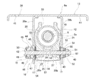
- FIG. 2 is a cross-sectional view showing a portion where the vehicle body side bracket is present in the steering column device shown in FIG.
- FIG. 3 is a cross-sectional view showing a portion of the steering column device shown in FIG. 1 in which an inner column and an outer column are taken out and a rotation preventing mechanism is incorporated.
- FIG. 4 is a perspective view of the steering column device shown in FIG. 1 as seen from the front side before a secondary collision occurs by removing some members.
- FIG. 5 is a perspective view of the steering column device shown in FIG.
- FIG. 6 is a perspective view showing a state before a secondary collision occurs in the steering column device shown in FIG. 1 with a part of the members taken out and the outer column being cut.
- FIG. 7 is a perspective view of the steering column device shown in FIG. 1, showing a state after a secondary collision occurs, with a part of the members taken out and the outer column being cut.
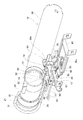
- FIG. 8 is a perspective view showing the inner column, the support bracket, the shock absorbing member, and the harness bracket of the steering device shown in FIG.
- FIG. 9 is an exploded perspective view showing the inner column, the support bracket, the shock absorbing member, and the harness bracket of the steering device shown in FIG. FIG.
- FIG. 10 is a perspective view showing the support bracket of the steering device shown in FIG.
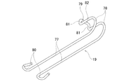
- FIG. 11 is a perspective view showing the shock absorbing member taken out of the steering device shown in FIG.
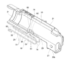
- FIG. 12 is a perspective view showing the steering device shown in FIG. 1 with the outer column and the impact absorbing member taken out and the outer column cut.
- FIG. 13 is a perspective view of the steering device shown in FIG. 1 when the outer column is taken out and viewed from the front side.
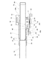
- FIG. 14 is a cross-sectional view showing a state of the steering column device shown in FIG. 1 before some secondary components are taken out and a secondary collision occurs.
- FIG. 15 is a cross-sectional view showing a state immediately after a part of the members of the steering column device shown in FIG. 1 is taken out and a secondary collision occurs.
- FIG. 16 is a cross-sectional view showing a state after a part of the members of the steering column device shown in FIG. 1 is taken out and the secondary collision progresses from the state shown in FIG.
- FIG. 17 (A) is a cross-sectional view showing a state before a secondary collision occurs by taking out one of the joining members that joins the inner column and the support bracket to the steering device shown in FIG. 1.
- FIG. 17B is a cross-sectional view showing a state after the secondary collision of the coupling member occurs.
- FIG. 18 is a perspective view showing an example of a conventional structure of a steering device.
- the steering column device 8a of the present example rotatably supports a steering shaft 2a having a steering wheel 1 (see FIG. 18) supported at its rear end portion with respect to a vehicle body.
- the steering column device 8a of this example includes a tilt / telescopic mechanism for adjusting the vertical position and the front-back position of the steering wheel 1, and an impact for alleviating the impact load applied to the driver's body in the event of a secondary collision. And an absorption mechanism.
- the vertical direction, the front-rear direction, and the width direction are the vertical direction, the front-rear direction, and the width direction when the steering column device 8a is assembled to the vehicle, unless otherwise specified.
- the steering shaft 2a has a structure in which the upper shaft 9 and the lower shaft 10 are combined by spline engagement or the like so that torque can be transmitted and the entire length can be expanded and contracted.
- the steering wheel 1 is supported and fixed to the rear end of the upper shaft 9.
- the key lock collar 11 that constitutes the steering lock device is externally fitted and fixed to the axially intermediate portion of the upper shaft 9.
- the steering column device 8a includes a steering column 12, a vehicle body side bracket 13, an adjusting rod 14, an adjusting lever 15 and a cam device 16 forming an expansion / contraction mechanism, a telescopic friction plate 17, a support bracket 18, and a shock absorbing member. And 19.
- the steering column 12 is configured to be expandable / contractible by fitting the front portion of the rear inner column 20 and the rear portion of the front outer column 21 into each other so as to allow relative displacement in the axial direction.
- the inner column 20 has notches 22 that are open to the front end surface at two locations that are spaced apart in the circumferential direction in the lower portion of the front end portion, and the inner column 20 is separated from the lower surface of the front portion in the axial direction.
- the through holes 23 are provided at the two locations.
- the inner column 20 of this example has a substantially rectangular locking through hole 24 in the rear portion.
- a lock unit (key lock cylinder) (not shown) is supported and fixed to a peripheral portion of the lock through hole 24 on the outer peripheral surface of the inner column 20.
- the lock pin of the lock unit is displaced inward in the radial direction of the steering column 12 through the lock through hole 24, and is formed on the outer peripheral surface of the key lock collar 11.
- the outer column 21 has a slit 25, a pair of clamped portions 26a and 26b, and a pair of column-side through holes 27.
- the slit 25 is for allowing the inner diameter of the rear portion of the outer column 21 to be expanded and contracted, and is formed on the lower surface from the middle portion to the rear portion of the outer column 21 so as to extend in the axial direction.
- the slit 25 has, at the front end, a wide portion 28 having a width dimension larger than that of the portion existing on the rear side.
- the rear end portion of the slit 25 is not opened to the rear end surface of the outer column 21, but it may be opened.
- the slit 25 is formed on the lower surface of the outer column 21, but it is also possible to form the slit on the upper surface of the outer column.
- the pair of sandwiched portions 26a and 26b are arranged at positions sandwiching the rear portion of the slit 25 from both sides in the width direction.
- Each of the pair of column-side through holes 27 is a mere circular hole, and is located at a portion of the pair of sandwiched portions 26a and 26b that are aligned with each other (that is, is coaxial with the pair of sandwiched portions 26a and 26b). ), And each of the pair of clamped portions 26a and 26b is formed so as to penetrate in the width direction.
- the outer column 21 further has a recessed portion 29, of which the rear end portion opens to the front end portion of the slit 25 and which extends in the axial direction, in the portion existing on the front side of the slit 25 on the inner peripheral surface. .
- the recessed portion 29 is inclined toward the rear end in a direction in which the depth dimension in the radial direction becomes deeper toward the rear side, in other words, in the direction in which the thickness dimension of the outer column 21 decreases.
- the concave portion 29 has a second guide surface 88 at the rear end, which is inclined in a direction in which the widthwise dimension becomes wider toward the rear side.
- the front end of the recess 29 is open to the front end surface of the outer column 21.
- the outer column 21 of this example has a fitting holding portion 31 having an inner diameter larger than that of a portion adjacent to the rear side on the inner peripheral surface of the front end portion, and at the rear end of the fitting holding portion 31, It has a step portion 32 facing the front side. Further, the outer column 21 has a rotation stopping slit 33 extending in the axial direction on the upper surface from the front portion to the rear portion. The front and rear end portions of the rotation stopping slit 33 are not open to the front and rear end surfaces of the outer column 21. That is, the detent slit 33 is an elongated hole extending in the axial direction.
- the front portion of the inner column 20 and the rear portion of the outer column 21 are fitted and supported on the upper surface of the inner column 20 as shown in FIG.
- the anti-rotation member 34 is arranged inside the anti-rotation slit 33 so as to be capable of relative displacement in the axial direction without rattling in the width direction. As a result, relative rotation between the inner column 20 and the outer column 21 is prevented. Note that details of the rotation stopping mechanism including the rotation stopping slit 33 and the rotation stopping member 34 are described in detail in International Publication No. WO 2016/114034 and are not related to the gist of the present invention, and therefore will be omitted. Further, if the relative rotation of the inner column 20 and the outer column 21 can be prevented by another means, the detent mechanism can be omitted.
- the steering column 12 of this example further includes an intermediate column 35 and a lower column 36.
- the rear end of the intermediate column 35 is internally fitted and fixed to the fitting holding portion 31 of the outer column 21 by interference fitting with the rear end face of the intermediate column 35 abutting against the step portion 32 of the outer column 21.
- the rear end of the lower column 36 is internally fitted to the front end of the intermediate column 35 so as to allow relative displacement in the axial direction. For this reason, in the steering column 12 of the present example, when a load directed rearward is applied to the lower column 36 due to a primary collision, the lower column 36 is displaced rearward with respect to the intermediate column 35, as will be described later. Is configured.
- the steering column 12 has its front end supported so that it can swing vertically with respect to the vehicle body.
- an annular bush 37 made of an elastic material such as an elastomer such as rubber or a synthetic resin is externally fitted and fixed to the front end of the lower column 36 to form the bush 37 on the vehicle body. It is internally fitted and fixed in the formed coupling hole.
- the front end of the steering column 12 is supported with respect to the vehicle body so as to be swingable in the vertical direction within a range in which the bush 37 can be elastically deformed.
- the steering shaft 2a rotatably supports the rear portion of the upper shaft 9 to the rear end of the inner column 20 via a rolling bearing, and the front portion of the lower shaft 10 to the front end of the lower column 36. And is rotatably supported via another rolling bearing. As a result, the steering shaft 2a is rotatably supported on the inner diameter side of the steering column 12.
- the vehicle body side bracket 13 switches the axial middle portion of the steering column 12 between an unclamped state in which the vertical position and the front-back position of the steering wheel 1 can be adjusted and a clamped state in which the steering wheel 1 is held at the adjusted position. Support as much as possible.
- the vehicle body side bracket 13 has a mounting plate portion 38, a pair of support plate portions 39a and 39b, and a pair of vehicle body side through holes 40.
- the mounting plate portion 38 has a pair of mounting holes 41 on both sides in the width direction.
- the vehicle body side bracket 13 is supported and fixed to the vehicle body so as not to fall off by a bolt inserted through the pair of mounting holes 41.
- the pair of support plate portions 39a and 39b are arranged so as to sandwich the pair of clamped portions 26a and 26b of the outer column 21 from both sides in the width direction.
- the pair of support plate portions 39a and 39b are joined and fixed by welding or the like to the upper end portions of the lower surface of the mounting plate portion 38 at two positions separated in the width direction. That is, the pair of support plate portions 39 a and 39 b hang downward from two positions on the lower surface of the mounting plate portion 38 that are separated in the width direction.
- the pair of vehicle body-side through holes 40 are formed in portions of the pair of support plate portions 39a and 39b that are aligned with each other.
- each of the vehicle body side through holes 40 is an elongated hole extending in the vertical direction. More specifically, each of the vehicle body side through holes 40 extends in an arc direction centered on the swing center in the vertical direction of the steering column 12.
- the adjusting rod 14 has a pair of column side through holes 27 and a pair of vehicle body side through holes 40 inserted in the width direction.
- the adjustment rod 14 has a head portion 42 at one end (left side in FIG. 2) in the axial direction of the adjustment rod 14, and a male screw at the other end (right side in FIG. 2) in the axial direction of the adjustment rod 14. It has a part 43.
- one of the pair of support plate portions 39a, 39b (left side in FIG. 2), a portion protruding from the outer surface of the support plate portion 39a has a width
- the adjustment lever 15 and the cam device 16 are arranged in this order from the outside in the direction. In other words, the adjustment lever 15 and the cam device 16 are arranged between the head portion 42 and the outer surface of the support plate portion 39a.
- the cam device 16 includes a driven side cam 44 arranged on the inner side in the width direction and a driving side cam 45 arranged on the outer side in the width direction.
- the driven cam 44 is made of sintered metal, has a driven cam surface 46 that is an uneven surface in the circumferential direction on the outer surface in the width direction of the vehicle body, and projects inward in the width direction on the inner surface.
- the engaging protrusion 47 has a substantially rectangular shape.
- the driven cam 44 is externally fitted to the adjusting rod 14 so as to be capable of relative rotation with respect to the adjusting rod 14 and relative displacement in the axial direction of the adjusting rod 14.
- the driven side cam 44 engages the engaging convex portion 47 with the vehicle body side through hole 40 formed in the one support plate portion 39a so that only the displacement along the vehicle body side through hole 40 is possible. There is.
- the drive-side cam 45 is made of sintered metal and has a drive-side cam surface 48 that is an uneven surface in the circumferential direction on the inner side surface in the width direction of the vehicle body.
- the drive side cam 45 is fixed to the base of the adjusting lever 15, and reciprocally rotates as the adjusting lever 15 reciprocates.
- the fitting convex portion 49 formed on the outer side surface of the drive side cam 45 in the width direction of the vehicle body and the fitting hole 50 formed in the base portion of the adjustment lever 15 are non-circularly fitted.
- the base portion of the adjusting lever 15 and the driving side cam 45 may be externally fitted to the adjusting rod 14 so as to rotate integrally with the adjusting rod 14, or may be fitted to the adjusting rod 14 so as to be rotatable relative thereto. You can also
- a portion outside the outer surface of the support plate portion 39b of the other (right side in FIG. 2) of the pair of support plate portions 39a, 39b is surrounded by a width direction outer side.
- the nut 51 and the thrust bearing 52 are arranged in this order from.
- the nut 51 is screwed onto the male screw portion 43 of the adjusting rod 14.
- the adjustment lever 15 is swung to expand or contract the axial dimension of the cam device 16, that is, the dimension in the width direction of the vehicle body.
- the interval between the pair of support plate portions 39a, 39b can be expanded / contracted. That is, in this example, the driven cam 44 and the thrust bearing 52 of the cam device 16 are a pair of pressing portions, and the adjusting lever 15 and the cam device 16 constitute an expansion / contraction device.
- the telescopic friction plate 17 is arranged to increase the holding force of the steering column 12 with respect to the vehicle body side bracket 13.
- a friction plate unit 54 which is formed by sandwiching one fixed-side friction plate 53 between a pair of telescopic friction plates 17, is provided with a pair of sandwiched portions 26a and 26b in the width direction outer surface.
- the holding force of the steering column 12 is further increased by arranging the supporting plates 39a and 39b at the portions between the inner surfaces in the width direction, respectively.
- Each of the telescopic friction plates 17 is made of a metal plate such as a steel plate having a large friction coefficient with respect to the widthwise inner side surfaces of the support plate portions 39a and 39b and the widthwise outer side surfaces of the sandwiched portions 26a and 26b. It is a rectangle.
- Each of the telescopic friction plates 17 has a telescopic elongated hole 55 extending in the axial direction of the steering column 12 in the range from the intermediate portion to the rear portion, and has a substantially rectangular support hole 56 in the front portion.
- the adjusting rod 14 is inserted into the telescopic elongated hole 55, and the front portion is supported by the inner column 20 via the support bracket 18.
- Each of the fixed-side friction plates 53 is made of a metal plate such as a steel plate having a large friction coefficient with respect to the side surface of the telescopic friction plate 17, and has a circular hole 87 for inserting the adjusting rod 14.
- the fixed-side friction plate 53 connects the central portions of the lower ends thereof with a connecting plate portion 57.
- the connecting plate portion 57 is arranged below the pair of held portions 26a and 26b.
- the fixed-side friction plate 53 is displaced in synchronization with the adjustment rod 14 when adjusting the vertical position or the front-back position of the steering wheel 1. That is, the fixed-side friction plate 53 is displaced in the vertical direction together with the adjusting rod 14 when adjusting the vertical position of the steering wheel 1, and remains at that position when adjusting the front-back position of the steering wheel 1. .
- the support bracket 18 is supported on the lower surface of the inner column 20 so as to be separable based on the impact load applied to the inner column 20 during a secondary collision. Further, the support bracket 18 supports the telescopic friction plate 17 so that the telescopic friction plate 17 can be displaced in the width direction.
- the support bracket 18 includes a bracket base portion 58, a mounting portion 59, a pair of support arm portions 60 a and 60 b, and a pair of handle portions 61.
- the bracket base portion 58 has a rectangular column shape, and has a cylindrical boss portion 62 at the center of the lower surface.
- the mounting portion 59 has a rectangular plate shape, and extends rearward from an upper end of the rear end surface of the bracket base 58.
- the mounting portion 59 has through holes 63 at two positions separated from each other in the axial direction.
- the support arm portions 60a and 60b extend in the width direction from both side surfaces in the width direction of the bracket base portion 58, and the support protrusions 64 on the width direction outer side with respect to the base end portion 65 on the width direction inner side as viewed in the front-rear direction. It has a crank-shaped side surface that is offset to the upper side.
- the support protrusion 64 has a rectangular column shape.
- the support protrusions 64 are inserted into the support holes 56 of the telescopic friction plates 17 constituting the friction plate units 54 so that the support protrusions 64 can be displaced in the width direction without rattling in the front-rear direction.
- each of the telescopic friction plates 17 is supported by the support bracket 18 so as to be displaceable in the width direction.
- Each of the base end portions 65 has a concave groove 66 formed so as to be continuous with the lower surface and the rear side surface of the end portion on the inner side in the width direction, and a portion of the bottom surface of the concave groove 66 facing the rear side (
- the handle portion 61 is provided on a portion formed on the rear side surface of the base end portion 65).
- each of the handling parts 61 is a partial cylindrical surface.
- the handling portion 61 may be a composite surface formed by combining a plurality of curved surfaces and / or flat surfaces.
- one of the support arm portions 60 a and 60 b has a screw hole 67 on the lower surface of the base end portion 65 of one support arm portion 60 a.
- the support bracket 18 is separably supported on the lower surface of the inner column 20 by the connecting member 68 based on the impact load applied to the inner column 20 in the case of a secondary collision.
- Each of the coupling members 68 includes an outer pin 69 and an inner pin 70, which are made of synthetic resin.
- the outer pin 69 is formed into a tubular shape as a whole, and includes a cylindrical portion 71 and a base end portion (lower end portion in FIG. 17A) outer peripheral surface of the cylindrical portion 71.
- An outward flange portion 72 that projects outward in the radial direction and a slot portion 73 that is disposed adjacent to the tip end side of the cylindrical portion 71 (upper side in FIG. 17A) are provided.
- the slot portion 73 has slits open at the end face on the tip side at two positions on the radially opposite side. Further, the slot portion 73 has a substantially triangular generatrix shape. That is, the outer diameter dimension of the slot portion 73 is larger than the outer diameter dimension of the cylindrical portion 71. On the other hand, the inner diameter dimension of the slot portion 73 is equal to the inner diameter dimension of the cylindrical portion 71.
- the inner pin 70 has a shaft portion 75 and a head portion 76 formed at the base end portion of the shaft portion 75.
- the front portion of the inner column 20 and the rear portion of the outer column 21 are fitted so as to be capable of relative displacement in the axial direction, and the detent member 34 is provided. Is arranged inside the rotation stopping slit 33. In this state, the through hole 23 of the inner column 20 exists inside the slit 25 of the outer column 21. Next, the through hole 63 of the support bracket 18 and the through hole 23 of the inner column 20 are aligned. That is, the axial position of the support bracket 18 with respect to the inner column 20 is adjusted so that the through hole 63 and the through hole 23 are coaxial.
- the slotted portion 73 of the outer pin 69 is elastically contracted from below into the through hole 63 of the support bracket 18 and the through hole 23 of the inner column 20, and then restored.
- the cylindrical portion 71 of the outer pin 69 is arranged inside the through hole 63 and the through hole 23, and the mounting portion 59 of the support bracket 18 and the inner column 20 are disposed between the outward flange portion 72 and the slit portion 73.
- the coupling member 68 is sheared and the inner column 20 and the support bracket 18 are separated.
- the shaft portion 75 of the inner pin 70 is press-fitted inside the outer pin 69 in the radial direction to prevent the slit portion 73 of the outer pin 69 from shrinking.
- the support bracket 18 is separably supported on the lower surface of the inner column 20 based on the forward-directed impact load applied to the inner column 20 during a secondary collision.
- the synthetic resin is injected into the through holes 63 and the through holes 23 (injection molding), or a synthetic resin or light alloy element pin molded in a cylindrical shape in advance is used as the through holes 63 and the through holes 23. It is also possible to support the support bracket 18 against the lower surface of the inner column 20 by press-fitting into the inner bracket 20.
- the shock absorbing member 19 is formed by bending a wire made of a metal such as mild steel, and has a pair of extending portions 77 extending in the axial direction and a pair of extending portions 77 on the rear side of the extending portions 77. It is provided with a pair of folded-back portions 78 that are bent in a U-shape about 180 degrees from the end portions toward the upper side and the front side, and a base portion 79 that connects the front-side end portions of the pair of folded-back portions 78.
- each of the extending portions 77 is provided with a curved portion 80 that is bent in a substantially U shape from the front end toward the outer side in the width direction and rearward by more than 180 degrees.
- the base portion 79 has a pair of bent portions 81 bent upward from the front end portions of the pair of folded portions 78 at right angles and upper end portions of the pair of bent portions 81. And a connecting portion 82 for connecting.
- the shock absorbing member 19 is bridged between the inner column 20 and the support bracket 18, which are portions that are axially displaced relative to each other in the case of a secondary collision. Specifically, the shock absorbing member 19 engages each of the pair of bent portions 81 with each of the cutout portions 22 of the inner column 20, and at the same time, the inner peripheral surface (front side surface) of the pair of folded portions 78. Are opposed to the handle portion 61 of the support bracket 18. Further, the rear side portions of the pair of extending portions 77 are arranged inside the concave portion 66 of the support bracket 18 that faces downward (the portion formed on the lower surface of the base end portion 65). .
- a pair of bent portions 81 are formed in a state where the shock absorbing member 19 is bridged between the inner column 20 and the support bracket 18 (before the secondary collision occurs).
- a gap is provided between the cutout portion 22 and the rear end portion of the cutout portion 22 and between the pair of folded portions 78 and the handling portion 61.
- the length dimension of the gap between the pair of bent portions 81 and the rear end portion of the cutout portion 22 is set to be between the pair of folded portions 78 and the handling portion 61. It is smaller than the length of the gap in the part.
- the length dimension of the gap between the pair of bent portions 81 and the rear end portion of the cutout portion 22, and the pair of folded portions 78 and the handle portion 61 is made. It is possible to make the total sum of the length dimension of the gap in the portion between and 3 mm or more and 15 mm or less, preferably 6 mm or more and 10 mm or less.
- the steering column device 8a of this example further includes a harness bracket 83 for supporting the wire harness.
- the harness bracket 83 is formed by stamping and bending a metal plate such as a steel plate with a press.
- the harness bracket 83 has an oval receiving hole 84 extending in the width direction at the center in the width direction of the front side portion, and has a circular hole 85 in the width direction one side portion of the front side portion.
- the harness bracket 83 engages the receiving hole 84 with the boss portion 62 of the support bracket 18 (inserts the boss portion 62 into the receiving hole 84) and inserts the screw 86 inserted through the circular hole 85 into the screw hole of the support bracket 18. It is supported and fixed to the support bracket 18 by being screwed onto 67 and further tightened. As a result, when the shock absorbing member 19 is plastically deformed due to the secondary collision, the harness bracket 83 is located behind the pair of extending portions 77 arranged inside the concave groove 66 of the support bracket 18 by the upper surface. By suppressing the side portion from the lower side, the extending portion 77 is prevented from being deformed so as to swing downward. That is, in this example, the harness bracket 83 has a function as a restraining portion.
- the vertical position of the steering wheel 1 can be adjusted within a range in which the adjusting rod 14 can move inside the vehicle body side through hole 40 of the vehicle body side bracket 13, and the adjusting rod 14 can be adjusted to a telescopic position.
- the front-back position of the steering wheel 1 can be adjusted within a range where the friction plate 17 can move inside the telescopic elongated hole 55.
- the drive side cam 45 is rotated in the locking direction by swinging the adjusting lever 15 in the direction opposite to the predetermined direction (for example, upward).
- the tip end surface of the convex portion of the driving side cam surface 48 and the tip end surface of the convex portion of the driven side cam surface 46 abut against each other, thereby expanding the axial dimension of the cam device 16 and driving the driven side cam 44.
- the thrust bearing 52 is shortened.
- the contact pressure between the inner side surfaces of the support plate portions 39a and 39b and the outer side surfaces of the sandwiched portions 26a and 26b increases, and at the same time, the inner diameter of the rear portion of the outer column 21 elastically contracts.
- the surface pressure of the contact portion between the inner peripheral surface of the rear portion of the outer column 21 and the outer peripheral surface of the front portion of the inner column 20 increases.
- the steering wheel 1 is held at the adjusted position.
- the lower column 36 which is rotatably supported via rolling bearings, is relatively displaced rearward with respect to the intermediate column 35 so as to reduce the overall length of the steering column 12.
- the steering wheel 1 is prevented from being displaced so as to be pushed up rearward.
- a secondary collision may occur in which the driver's body collides with the steering wheel 1.
- a frontward impact load is applied from the steering wheel 1 to the inner column 20 via the upper shaft 9.
- a forward impact load is applied to the inner column 20
- the inner column 20 tries to be displaced forward with respect to the vehicle body with respect to the vehicle body side bracket 13 and the support bracket 18 supported by the telescopic friction plate 17.
- a shearing force is generated between the inner column 20 and the support bracket 18, and the joining member 68 is sheared by this shearing force.
- forward displacement of the inner column 20 the upper shaft 9 and the steering wheel 1 supported by the inner column 20 is allowed, and the impact load applied to the driver's body is reduced.
- the shock absorbing member 19 spanned between the inner column 20 and the support bracket 18 is plastically deformed. That is, when the inner column 20 is displaced forward and the base portion 79 of the shock absorbing member 19 is pulled forward, the pair of folded-back portions 78 of the shock absorbing member 19 are pressed against the handle portion 61 of the support bracket 18. From this state, when the inner column 20 is further displaced forward, the portion that was the folded-back portion 78 is handled by the handling portion 61 and moves forward (to the straight line portion that connects the folded-back portion 78 and the base 79).
- the portion that was the extending portion 77 is fed into the portion that is handled by the handling portion 61 and is curved to become the folded-back portion 78.
- the inner column 20 is configured to be displaced forward while plastically deforming the shock absorbing member 19, so that the shock load applied to the body of the driver who collides with the steering wheel 1 is further increased. Can be relaxed.
- the coupling member 68 is sheared, and the inner column 20 starts to move forward, the impact absorbing member 19 is plastically deformed to start absorbing the impact load.
- the idling section where the shock absorbing member 19 cannot be plastically deformed is substantially (a pair of the bent portion 81 and the notch portion 22 It is possible to eliminate the idle running portion based on the gap existing between the end portion and the portion between the pair of folded-back portions 78 and the handle portion 61).
- the concave portion 29 has a second guide surface 88 at the rear end, which is inclined in a direction in which the widthwise dimension becomes wider toward the rear side.
- the portion of the shock absorbing member 19 that connects the lower end of the pair of bent portions 81 of the base 79 and the upper end of the pair of folded portions 78 is defined by the handle portion 61. Even when it is deformed so as to expand in the width direction when it is handled, it can be guided to the inside of the recess 29 by the second guide surface 88.
- the steering column device 8a of this example is configured such that the inner column 20 is displaced forward due to the impact load at the time of the secondary collision, but does not fall off even when the secondary collision progresses. Therefore, even when the secondary collision progresses, the steering wheel 1 can be prevented from being excessively displaced downward, and, for example, when the accident vehicle is capable of self-propelled, the accident vehicle can be driven from the accident site to the road shoulder. This makes it easier to drive when moving.
- the steering column device 8a of this example includes a shock absorbing member 19 that absorbs a shock load caused by a secondary collision by plastically deforming due to the forward displacement of the inner column 20 in the case of a secondary collision. Therefore, according to the steering column device 8a of this example, the amount of absorption of the impact load applied to the steering wheel 1 at the time of a secondary collision is compared with that of the steering column device described in International Publication No. 2016/114034. Can be made larger.
- the support bracket 18 is supported at a central position in the width direction on the lower surface of the inner column 20, and the shock absorbing member 19 is arranged so as to span the support bracket 18 and the inner column 20. That is, since the shock absorbing member 19 can be arranged at the center position in the width direction of the inner column 20, the posture of the shock absorbing member 19 at the time of the secondary collision can be stabilized, and the shock absorbing member 19 is plastically deformed. It is easy to stabilize the shock absorption performance.
- the impact absorbing member 19 is extended between the inner column 20 and the support bracket 18 (the state before the secondary collision occurs), and the pair of bent portions 81 and the notch portion 22 are deep inside.
- a gap is made to exist between the end portion and the pair of folded-back portions 78 and the handle portion 61. Therefore, even after the support bracket 18 is coupled to the inner column 20, the shock absorbing member 19 can be easily assembled between the inner column 20 and the support bracket 18.
- the length dimension of the gap between the pair of bent portions 81 and the rear end portion of the cutout portion 22 is set to the pair of folded portions 78 and the handle portion 61. It is smaller than the length of the gap in the space. Therefore, it is possible to prevent the shock absorbing member 19 from falling off from the inner column 20 from the state in which the shock absorbing member 19 is bridged between the inner column 20 and the support bracket 18.
- the plastic deformation of the shock absorbing member 19 can be started after the coupling member 68 is surely sheared. As a result, it is possible to suppress variations in the shock absorbing characteristics due to the plastic deformation of the shock absorbing member 19.
- the outer column 21 has a front end of a recess 29 formed in a portion of the inner peripheral surface existing on the front side of the slit 25, which is open to the front end surface of the outer column 21. Therefore, even if the outer column 21 is manufactured by casting, the mold can be pulled out without difficulty. Further, since the rigidity in the radial direction of the fitting holding portion 31 formed on the inner peripheral surface of the front end of the outer column 21 can be appropriately reduced, the fitting holding portion 31 is provided with a rear side of the intermediate column 35. The press-fitting load at the time of press-fitting the ends of the can be suppressed and stabilized.
Abstract
[Problem] To realize a structure with which it is easy to increase the quantity of absorption of an impact load applied to a steering wheel when a secondary impact occurs. [Solution] A support bracket 18 is disposed on the inner side of a slit 25 of an outer column 21 and is joined to an inner column 20 so as to be separable on the basis of an impact load applied to the inner column 20 when a secondary impact occurs. A base section 79 of an impact absorption member 19 is attached to the inner column 20 so that, when the inner column 20 is displaced forward, the base section 79 is displaced together with the inner column 20, and a folded-back section is made to face a girdle section of the support bracket 18.
Description
本発明は、ステアリングホイールを支持したステアリングシャフトを回転自在に支持するためのステアリングコラム装置に関する。
The present invention relates to a steering column device for rotatably supporting a steering shaft that supports a steering wheel.
図18は、自動車用のステアリング装置の1例を示している。ステアリングホイール1の回転は、ステアリングシャフト2、自在継手3、中間シャフト4などを介して、ステアリングギヤユニット5に伝達され、ステアリングギヤユニット5で直線運動に変換される。ステアリングギヤユニット5の直線運動により、左右のタイロッド6を押し引きすることで、操舵輪7に舵角が付与される。ステアリングシャフト2は、ステアリングコラム装置8を介して、車体に対して回転可能に支持される。
FIG. 18 shows an example of a steering device for an automobile. The rotation of the steering wheel 1 is transmitted to the steering gear unit 5 via the steering shaft 2, the universal joint 3, the intermediate shaft 4, etc., and is converted into a linear motion by the steering gear unit 5. A steering angle is imparted to the steered wheels 7 by pushing and pulling the left and right tie rods 6 by the linear movement of the steering gear unit 5. The steering shaft 2 is rotatably supported with respect to the vehicle body via a steering column device 8.
国際公開第2016/114034号パンフレットには、ステアリングホイールの位置を調節可能とするためのチルト・テレスコピック機構、および、二次衝突の際に、運転者の身体に加わる衝撃荷重を緩和するための衝撃吸収機構を備えたステアリングコラム装置が記載されている。このステアリング装置では、ステアリングシャフトを、インナシャフトとアウタシャフトとを組み合わせることにより、全長を伸縮可能に構成し、かつ、ステアリングコラムを、前側のアウタコラムの後側部分と、後側のインナコラムの前側部分とを軸方向に変位可能に嵌合させることにより、全長を伸縮可能に構成している。また、インナコラムの前側部分の下面に、インナコラムブラケットを、合成樹脂製のシェアピンにより結合固定している。二次衝突時に、ステアリングホイールからステアリングシャフトを介して、インナコラムに前方に向いた大きな衝撃荷重が加わると、シェアピンが剪断される。この結果、ステアリングホイールの前方への変位が許容され、運転者の身体に加わる衝撃荷重が緩和される。
International Publication No. WO 2016/114034 discloses a tilt / telescopic mechanism for adjusting the position of a steering wheel and a shock for reducing a shock load applied to a driver's body in the case of a secondary collision. A steering column device having an absorption mechanism is described. In this steering device, the entire length of the steering shaft is made expandable by combining the steering shaft with the inner shaft and the outer shaft, and the steering column is composed of the rear portion of the front outer column and the rear inner column. By fitting the front portion so as to be displaceable in the axial direction, the entire length can be expanded and contracted. Further, an inner column bracket is joined and fixed to the lower surface of the front portion of the inner column by a shear pin made of synthetic resin. During a secondary collision, if a large forward impact load is applied to the inner column from the steering wheel via the steering shaft, the shear pin is sheared. As a result, the steering wheel is allowed to move forward, and the impact load applied to the driver's body is reduced.
衝撃吸収機構を備えるステアリングコラム装置においては、二次衝突の際に、ステアリングホイールに加わる衝撃荷重の吸収量を適度に大きくすることが好ましく、この点において、国際公開第2016/114034号パンフレットに記載のステアリングコラム装置には改良の余地がある。
In a steering column device having an impact absorbing mechanism, it is preferable to appropriately increase the amount of impact load applied to the steering wheel at the time of a secondary collision, and in this respect, it is described in International Publication No. WO 2016/114034. There is room for improvement in the steering column device.
本発明は、上述のような事情に鑑み、二次衝突の際に、ステアリングホイールに加わる衝撃荷重の吸収量を大きくしやすい、ステアリングコラム装置の構造を実現することを目的としている。
The present invention has been made in view of the above circumstances, and an object thereof is to realize a structure of a steering column device in which it is easy to increase the amount of impact load applied to a steering wheel in the event of a secondary collision.
本発明のステアリングコラム装置は、インナコラムと、アウタコラムと、車体側ブラケットと、調節ロッドと、1対の押圧部と、拡縮機構と、テレスコ摩擦板と、支持ブラケットと、衝撃吸収部材とを備える。
The steering column device of the present invention includes an inner column, an outer column, a vehicle body side bracket, an adjusting rod, a pair of pressing portions, a scaling mechanism, a telescopic friction plate, a support bracket, and a shock absorbing member. Prepare
前記インナコラムの前側部分は、前記アウタコラムの後側部分に内嵌されている。前記アウタコラムは、軸方向に伸長するスリットと、該スリットを幅方向両側から挟む位置に配置された1対の被挟持部と、該1対の被挟持部のそれぞれを幅方向に貫通する1対のコラム側通孔とを有する。
The front part of the inner column is fitted inside the rear part of the outer column. The outer column has a slit extending in the axial direction, a pair of sandwiched portions arranged at positions sandwiching the slit from both sides in the width direction, and a pair of sandwiched portions penetrating in the width direction. It has a pair of column side through holes.
前記車体側ブラケットは、前記1対の被挟持部を挟持する1対の支持板部と、該1対の支持板部の互いに整合する部分に形成された1対の車体側通孔とを有する。
The vehicle body side bracket includes a pair of support plate portions that sandwich the pair of sandwiched portions, and a pair of vehicle body side through holes that are formed in portions of the pair of support plate portions that are aligned with each other. .
前記調節ロッドは、前記1対のコラム側通孔および前記1対の車体側通孔を挿通している。前記1対の押圧部は、前記調節ロッドのうちで、前記1対の支持板部の外側面から突出する部分に配置されている。前記拡縮機構は、前記1対の押圧部同士の間隔を拡縮する。
The adjustment rod is inserted through the pair of column side through holes and the pair of vehicle body side through holes. The pair of pressing portions are arranged in portions of the adjusting rod that project from the outer surfaces of the pair of support plate portions. The expansion / contraction mechanism expands / contracts the interval between the pair of pressing portions.
The adjustment rod is inserted through the pair of column side through holes and the pair of vehicle body side through holes. The pair of pressing portions are arranged in portions of the adjusting rod that project from the outer surfaces of the pair of support plate portions. The expansion / contraction mechanism expands / contracts the interval between the pair of pressing portions.
前記テレスコ摩擦板は、前記1対の支持板部の内側面と前記1対の被挟持部の外側面との間部分、および、前記1対の支持板部の外側面と前記1対の押圧部の内側面との間部分のうちの少なくとも1箇所の間部分に挟持され、前記調節ロッドが挿通されたテレスコ長孔を有する。
The telescopic friction plate has a portion between an inner surface of the pair of support plate portions and an outer surface of the pair of clamped portions, and an outer surface of the pair of support plate portions and the pair of pressing members. There is a telescopic elongated hole that is sandwiched by at least one of the portions between the inner side surface of the portion and the inner side surface and through which the adjustment rod is inserted.
前記支持ブラケットは、前記スリットの内側に配置され、かつ、前記インナコラムに対し、二次衝突の際に前記インナコラムに加わる衝撃荷重に基づいて分離可能に結合された取付部と、前記テレスコ摩擦板を支持する支持腕部と、後側を向いた面に形成された扱き部とを有する。
The support bracket is disposed inside the slit, and is attached to the inner column so as to be separably coupled based on an impact load applied to the inner column at the time of a secondary collision, and the telescopic friction. It has a support arm portion that supports the plate and a handle portion that is formed on the surface facing the rear side.
前記衝撃吸収部材は、線材からなり、基部と、該基部の後側の端部から、前記インナコラムの径方向に関して外側かつ前側に向けて折り返された折り返し部と、該折り返し部のうち、前記インナコラムの径方向に関する外側の端部から前側に向けて伸長する延出部とを有する。
The impact absorbing member is made of a wire rod, and includes a base portion, a rear end portion of the base portion that is folded back toward the outer side and the front side in the radial direction of the inner column, and the return portion. The inner column has an extending portion extending from the outer end portion in the radial direction toward the front side.
前記基部は、前記インナコラムに対し、該インナコラムが前方に変位する際に、該インナコラムとともに変位するように取り付けられている(固定される、あるいは係合する)。前記折り返し部は前記扱き部に対向している。
The base portion is attached (fixed or engaged) to the inner column so as to be displaced together with the inner column when the inner column is displaced forward. The folded-back portion faces the handle portion.
本発明のステアリングコラム装置は、前記二次衝突の際に、前記延出部を、前記インナコラムの径方向に関して外側から抑えるようにして、前記延出部が、前記インナコラムの径方向に関して外方に変形することを防止する抑え部を備えることが好ましい。この場合、前記抑え部は、前記支持ブラケットに支持固定されたハーネスブラケットからなることができる。
In the steering column device of the present invention, at the time of the secondary collision, the extending portion is restrained from the outside in the radial direction of the inner column so that the extending portion is outside in the radial direction of the inner column. It is preferable to provide a restraining portion that prevents the deformation to one side. In this case, the restraining portion may include a harness bracket supported and fixed to the support bracket.
前記アウタコラムは、内周面のうちで前記スリットの前側に存在する部分に、該スリットの前側の端部に開口し、かつ、径方向外側に向けて凹んだ凹部を備えることができる。この場合、前記凹部は、後側の端部に、後側に向かうほど深さ寸法が深くなる方向に傾斜した第1の案内面を有することができる。代替的または追加的に、前記凹部は、後側の端部に、後側に向かうほど幅方向寸法が広くなる方向に傾斜した第2の案内面を有することができる。
The outer column can be provided with a recessed portion that is open to the front end of the slit and that is recessed radially outward in a portion of the inner peripheral surface that is present on the front side of the slit. In this case, the recess may have a first guide surface at the rear end that is inclined in a direction in which the depth becomes deeper toward the rear side. Alternatively or additionally, the recess may have, at the rear end, a second guide surface that is inclined in a direction in which the widthwise dimension increases toward the rear side.
前記衝撃吸収部材において、前記折り返し部は1対の折り返し部からなり、前記延出部は、1対の延出部からなり、前記1対の折り返し部のそれぞれのうち、前記インナコラムの径方向に関する径方向内側の端部が前記基部により連結されている構成を採ることができる。この場合、前記インナコラムは、前側の端部のうち、周方向に離隔した2箇所位置に切り欠き部を有し、前記衝撃吸収部材の前記基部は、前記1対の折り返し部の前側の端部から直角に折れ曲がった1対の折れ曲がり部と、該1対の折れ曲がり部の端部同士を連結する連結部とを有し、前記切り欠き部のそれぞれに前記1対の折れ曲がり部のそれぞれが係合している構成を採ることができる。
In the shock absorbing member, the folded-back portion includes a pair of folded-back portions, the extending portion includes a pair of extending portions, and a radial direction of the inner column in each of the pair of folded-back portions. It is possible to adopt a configuration in which the ends on the radially inner side of are connected by the base. In this case, the inner column has cutout portions at two positions spaced apart in the circumferential direction among the front end portions, and the base portion of the shock absorbing member has front end portions of the pair of folded portions. A pair of bent portions bent at a right angle from the section, and a connecting portion that connects the ends of the pair of bent portions, and each of the pair of bent portions is engaged with each of the cutout portions. A matching configuration can be adopted.
本発明のステアリングコラム装置は、後側の端部が、前記アウタコラムの前側の端部に後方への変位を不能に嵌合している中間コラム、および、後側の端部が、前記中間コラムの前側の端部に、一次衝突に基づいて後方に向いた衝撃荷重が加わった場合に、後方へ変位することを可能に嵌合しているロアコラムを備えることができる。
In the steering column device of the present invention, the rear end portion is an intermediate column in which the rear end portion is fitted to the front end portion of the outer column so as not to be displaced rearward, and the rear end portion is the intermediate portion. The front end of the column may include a lower column that is fitted so as to be displaced rearward when a rearward impact load is applied due to a primary collision.
本発明のステアリングコラム装置では、二次衝突の際に、ステアリングホイールに加わる衝撃荷重の吸収量を、国際公開第2016/114034号パンフレットに記載のステアリングコラム装置と比較して大きくすることが可能となる。
In the steering column device of the present invention, the amount of impact load applied to the steering wheel at the time of a secondary collision can be made larger than that of the steering column device described in International Publication No. WO 2016/114034. Become.
図1~図17(B)は、本発明の実施の形態の1例を示している。本例のステアリングコラム装置8aは、後側の端部にステアリングホイール1(図18参照)が支持されたステアリングシャフト2aを、車体に対し回転可能に支持する。本例のステアリングコラム装置8aは、ステアリングホイール1の上下位置および前後位置を調節するためのチルト・テレスコピック機構と、二次衝突の際に、運転者の身体に加わる衝撃荷重を緩和するための衝撃吸収機構とを備える。なお、上下方向、前後方向、および幅方向とは、特に断らない限り、ステアリングコラム装置8aを車両に組み付けた状態での上下方向、前後方向、および幅方向をいう。
1 to 17 (B) show an example of an embodiment of the present invention. The steering column device 8a of the present example rotatably supports a steering shaft 2a having a steering wheel 1 (see FIG. 18) supported at its rear end portion with respect to a vehicle body. The steering column device 8a of this example includes a tilt / telescopic mechanism for adjusting the vertical position and the front-back position of the steering wheel 1, and an impact for alleviating the impact load applied to the driver's body in the event of a secondary collision. And an absorption mechanism. The vertical direction, the front-rear direction, and the width direction are the vertical direction, the front-rear direction, and the width direction when the steering column device 8a is assembled to the vehicle, unless otherwise specified.
ステアリングシャフト2aは、アッパシャフト9とロアシャフト10とをスプライン係合などにより、トルク伝達可能に、かつ、全長を伸縮可能に組み合わせた構造を有する。ステアリングホイール1は、アッパシャフト9の後側の端部に支持固定される。なお、本例では、ステアリングロック装置を構成するキーロックカラー11は、アッパシャフト9の軸方向中間部に外嵌固定されている。
The steering shaft 2a has a structure in which the upper shaft 9 and the lower shaft 10 are combined by spline engagement or the like so that torque can be transmitted and the entire length can be expanded and contracted. The steering wheel 1 is supported and fixed to the rear end of the upper shaft 9. In this example, the key lock collar 11 that constitutes the steering lock device is externally fitted and fixed to the axially intermediate portion of the upper shaft 9.
ステアリングコラム装置8aは、ステアリングコラム12と、車体側ブラケット13と、調節ロッド14と、拡縮機構を構成する調節レバー15およびカム装置16と、テレスコ摩擦板17と、支持ブラケット18と、衝撃吸収部材19とを備える。
The steering column device 8a includes a steering column 12, a vehicle body side bracket 13, an adjusting rod 14, an adjusting lever 15 and a cam device 16 forming an expansion / contraction mechanism, a telescopic friction plate 17, a support bracket 18, and a shock absorbing member. And 19.
ステアリングコラム12は、後側のインナコラム20の前側部分と前側のアウタコラム21の後側部分とを軸方向の相対変位を可能に嵌合させることにより、全長を伸縮可能に構成されている。
The steering column 12 is configured to be expandable / contractible by fitting the front portion of the rear inner column 20 and the rear portion of the front outer column 21 into each other so as to allow relative displacement in the axial direction.
インナコラム20は、前側の端部の下側部分のうち、周方向に離隔した2箇所に、前側の端面に開口した切り欠き部22を有するとともに、前側部分の下面のうち、軸方向に離隔した2箇所に、通孔23を有する。
The inner column 20 has notches 22 that are open to the front end surface at two locations that are spaced apart in the circumferential direction in the lower portion of the front end portion, and the inner column 20 is separated from the lower surface of the front portion in the axial direction. The through holes 23 are provided at the two locations.
本例のインナコラム20は、後側部分に、略矩形状のロック用透孔24を有する。インナコラム20の外周面のうち、ロック用透孔24の周辺部分に、図示しないロックユニット(キーロックシリンダ)が支持固定される。ステアリングロック装置の作動時(キーロック時)には、ロックユニットのロックピンを、ロック用透孔24を通じて、ステアリングコラム12の径方向に関して内側に変位させ、キーロックカラー11の外周面に形成された係合凹部に係合させることにより、ステアリングシャフト2aの回転を実質的に阻止することが可能である。
The inner column 20 of this example has a substantially rectangular locking through hole 24 in the rear portion. A lock unit (key lock cylinder) (not shown) is supported and fixed to a peripheral portion of the lock through hole 24 on the outer peripheral surface of the inner column 20. When the steering lock device is activated (when the key is locked), the lock pin of the lock unit is displaced inward in the radial direction of the steering column 12 through the lock through hole 24, and is formed on the outer peripheral surface of the key lock collar 11. By engaging with the engaging recess, it is possible to substantially prevent the rotation of the steering shaft 2a.
アウタコラム21は、スリット25と、1対の被挟持部26a、26bと、1対のコラム側通孔27とを有する。
The outer column 21 has a slit 25, a pair of clamped portions 26a and 26b, and a pair of column-side through holes 27.
スリット25は、アウタコラム21の後側部分の内径を拡縮可能とするためのもので、アウタコラム21の中間部から後側部分にかけての下面に、軸方向に伸長するように形成されている。スリット25は、前側の端部に、後側に存在する部分よりも幅寸法が大きい幅広部28を有する。本例では、スリット25の後側の端部は、アウタコラム21の後側の端面に開口していないが、開口させることもできる。本例では、スリット25をアウタコラム21の下面に形成しているが、スリットをアウタコラムの上面に形成することも可能である。
The slit 25 is for allowing the inner diameter of the rear portion of the outer column 21 to be expanded and contracted, and is formed on the lower surface from the middle portion to the rear portion of the outer column 21 so as to extend in the axial direction. The slit 25 has, at the front end, a wide portion 28 having a width dimension larger than that of the portion existing on the rear side. In this example, the rear end portion of the slit 25 is not opened to the rear end surface of the outer column 21, but it may be opened. In this example, the slit 25 is formed on the lower surface of the outer column 21, but it is also possible to form the slit on the upper surface of the outer column.
1対の被挟持部26a、26bは、スリット25の後側部分を幅方向両側から挟む位置に配置されている。1対のコラム側通孔27のそれぞれは、単なる円孔であり、1対の被挟持部26a、26bの互いに整合する部分に(すなわち、1対の被挟持部26a、26bに互いに同軸となるように)、かつ、1対の被挟持部26a、26bのそれぞれを幅方向に貫通するように形成されている。
The pair of sandwiched portions 26a and 26b are arranged at positions sandwiching the rear portion of the slit 25 from both sides in the width direction. Each of the pair of column-side through holes 27 is a mere circular hole, and is located at a portion of the pair of sandwiched portions 26a and 26b that are aligned with each other (that is, is coaxial with the pair of sandwiched portions 26a and 26b). ), And each of the pair of clamped portions 26a and 26b is formed so as to penetrate in the width direction.
アウタコラム21は、内周面のうち、スリット25の前側に存在する部分に、後側の端部がスリット25の前側の端部に開口し、かつ、軸方向に伸長する凹部29をさらに有する。凹部29は、後側の端部に、後側に向かうほど径方向に関する深さ寸法が深くなる方向に傾斜した、換言すれば、アウタコラム21の厚さ寸法が薄くなる方向に傾斜した第1の案内面30を有する。本例では、凹部29は、後側の端部に、後側に向かうほど幅方向寸法が広くなる方向に傾斜した第2の案内面88を有する。本例では、凹部29の前側の端部は、アウタコラム21の前側の端面に開口している。
The outer column 21 further has a recessed portion 29, of which the rear end portion opens to the front end portion of the slit 25 and which extends in the axial direction, in the portion existing on the front side of the slit 25 on the inner peripheral surface. . The recessed portion 29 is inclined toward the rear end in a direction in which the depth dimension in the radial direction becomes deeper toward the rear side, in other words, in the direction in which the thickness dimension of the outer column 21 decreases. Has a guide surface 30. In this example, the concave portion 29 has a second guide surface 88 at the rear end, which is inclined in a direction in which the widthwise dimension becomes wider toward the rear side. In this example, the front end of the recess 29 is open to the front end surface of the outer column 21.
本例のアウタコラム21は、前側の端部内周面に、後側に隣接する部分よりも内径寸法が大きい嵌合保持部31を有するとともに、嵌合保持部31の後側の端部に、前側を向いた段差部32を有する。さらに、アウタコラム21は、前側部分から後側部分にかけての上面に、軸方向に伸長する回り止め用スリット33を有する。なお、回り止め用スリット33の前後両側の端部は、アウタコラム21の前後両側の端面に開口していない。すなわち、回り止め用スリット33は、軸方向に伸長する長孔である。
The outer column 21 of this example has a fitting holding portion 31 having an inner diameter larger than that of a portion adjacent to the rear side on the inner peripheral surface of the front end portion, and at the rear end of the fitting holding portion 31, It has a step portion 32 facing the front side. Further, the outer column 21 has a rotation stopping slit 33 extending in the axial direction on the upper surface from the front portion to the rear portion. The front and rear end portions of the rotation stopping slit 33 are not open to the front and rear end surfaces of the outer column 21. That is, the detent slit 33 is an elongated hole extending in the axial direction.
本例では、インナコラム20の前側部分とアウタコラム21の後側部分とを軸方向に関する相対変位を可能に嵌合させた状態で、図3に示すように、インナコラム20の上面に支持固定した回り止め部材34が、回り止め用スリット33の内側に、幅方向のがたつきなく、かつ、軸方向の相対変位を可能に配置されている。これにより、インナコラム20とアウタコラム21との相対回転が防止される。なお、回り止め用スリット33と回り止め部材34とを含む回り止め機構に関する詳細については、国際公開第2016/114034号パンフレットに詳しく記載されており、本発明の要旨とも関係ないため、省略する。また、別の手段によりインナコラム20とアウタコラム21との相対回転を防止できるのであれば、前記回り止め機構を省略することもできる。
In this example, the front portion of the inner column 20 and the rear portion of the outer column 21 are fitted and supported on the upper surface of the inner column 20 as shown in FIG. The anti-rotation member 34 is arranged inside the anti-rotation slit 33 so as to be capable of relative displacement in the axial direction without rattling in the width direction. As a result, relative rotation between the inner column 20 and the outer column 21 is prevented. Note that details of the rotation stopping mechanism including the rotation stopping slit 33 and the rotation stopping member 34 are described in detail in International Publication No. WO 2016/114034 and are not related to the gist of the present invention, and therefore will be omitted. Further, if the relative rotation of the inner column 20 and the outer column 21 can be prevented by another means, the detent mechanism can be omitted.
本例のステアリングコラム12は、中間コラム35と、ロアコラム36とをさらに備える。中間コラム35は、後側の端面を、アウタコラム21の段差部32に突き当てた状態で、後側部分を、アウタコラム21の嵌合保持部31に締り嵌めで内嵌固定されている。ロアコラム36の後側の端部は、中間コラム35の前側の端部に、軸方向の相対変位を可能に内嵌されている。このため、本例のステアリングコラム12は、後述するように、一次衝突に伴って、ロアコラム36に後方に向いた荷重が加わると、ロアコラム36が中間コラム35に対し、後方に向けて変位するように構成されている。
The steering column 12 of this example further includes an intermediate column 35 and a lower column 36. The rear end of the intermediate column 35 is internally fitted and fixed to the fitting holding portion 31 of the outer column 21 by interference fitting with the rear end face of the intermediate column 35 abutting against the step portion 32 of the outer column 21. The rear end of the lower column 36 is internally fitted to the front end of the intermediate column 35 so as to allow relative displacement in the axial direction. For this reason, in the steering column 12 of the present example, when a load directed rearward is applied to the lower column 36 due to a primary collision, the lower column 36 is displaced rearward with respect to the intermediate column 35, as will be described later. Is configured.
ステアリングコラム12は、前側の端部を、車体に対して上下方向の揺動を可能に支持している。具体的には、図1に示すように、ロアコラム36の前側の端部に、ゴムなどのエラストマー、合成樹脂などの弾性材製で環状のブッシュ37を外嵌固定し、ブッシュ37を車体に形成された結合孔に内嵌固定している。これにより、ステアリングコラム12の前側の端部は、車体に対して、ブッシュ37が弾性変形できる範囲で上下方向の揺動を可能に支持される。
The steering column 12 has its front end supported so that it can swing vertically with respect to the vehicle body. Specifically, as shown in FIG. 1, an annular bush 37 made of an elastic material such as an elastomer such as rubber or a synthetic resin is externally fitted and fixed to the front end of the lower column 36 to form the bush 37 on the vehicle body. It is internally fitted and fixed in the formed coupling hole. Thus, the front end of the steering column 12 is supported with respect to the vehicle body so as to be swingable in the vertical direction within a range in which the bush 37 can be elastically deformed.
ステアリングシャフト2aは、アッパシャフト9の後側部分を、インナコラム20の後側の端部に転がり軸受を介して回転自在に支持し、ロアシャフト10の前側部分を、ロアコラム36の前側の端部に別の転がり軸受を介して回転自在に支持することにより構成されている。これにより、ステアリングシャフト2aは、ステアリングコラム12の内径側に回転自在に支持される。
The steering shaft 2a rotatably supports the rear portion of the upper shaft 9 to the rear end of the inner column 20 via a rolling bearing, and the front portion of the lower shaft 10 to the front end of the lower column 36. And is rotatably supported via another rolling bearing. As a result, the steering shaft 2a is rotatably supported on the inner diameter side of the steering column 12.
車体側ブラケット13は、ステアリングコラム12の軸方向中間部を、ステアリングホイール1の上下位置および前後位置を調節可能なアンクランプ状態と、ステアリングホイール1を調節後の位置に保持するクランプ状態とを切り替え可能に支持する。本例では、車体側ブラケット13は、取付板部38と、1対の支持板部39a、39bと、1対の車体側通孔40とを有する。
The vehicle body side bracket 13 switches the axial middle portion of the steering column 12 between an unclamped state in which the vertical position and the front-back position of the steering wheel 1 can be adjusted and a clamped state in which the steering wheel 1 is held at the adjusted position. Support as much as possible. In this example, the vehicle body side bracket 13 has a mounting plate portion 38, a pair of support plate portions 39a and 39b, and a pair of vehicle body side through holes 40.
取付板部38は、幅方向両側部分に1対の取付孔41を有する。車体側ブラケット13は、1対の取付孔41を挿通したボルトにより、車体に対して脱落不能に支持固定される。
The mounting plate portion 38 has a pair of mounting holes 41 on both sides in the width direction. The vehicle body side bracket 13 is supported and fixed to the vehicle body so as not to fall off by a bolt inserted through the pair of mounting holes 41.
1対の支持板部39a、39bは、アウタコラム21の1対の被挟持部26a、26bを幅方向両側から挟持するように配置されている。本例では、1対の支持板部39a、39bは、上側の端部を、取付板部38の下面のうち、幅方向に離隔した2箇所位置に、溶接などにより結合固定されている。すなわち、1対の支持板部39a、39bは、取付板部38の下面のうち、幅方向に離隔した2箇所位置から下方に向けて垂下している。
The pair of support plate portions 39a and 39b are arranged so as to sandwich the pair of clamped portions 26a and 26b of the outer column 21 from both sides in the width direction. In this example, the pair of support plate portions 39a and 39b are joined and fixed by welding or the like to the upper end portions of the lower surface of the mounting plate portion 38 at two positions separated in the width direction. That is, the pair of support plate portions 39 a and 39 b hang downward from two positions on the lower surface of the mounting plate portion 38 that are separated in the width direction.
1対の車体側通孔40は、1対の支持板部39a、39bの互いに整合する部分に形成されている。本例では、車体側通孔40のそれぞれは、上下方向に伸長する長孔からなる。より具体的には、車体側通孔40のそれぞれは、ステアリングコラム12の上下方向に関する揺動中心を中心とする円弧方向に伸長している。
The pair of vehicle body-side through holes 40 are formed in portions of the pair of support plate portions 39a and 39b that are aligned with each other. In this example, each of the vehicle body side through holes 40 is an elongated hole extending in the vertical direction. More specifically, each of the vehicle body side through holes 40 extends in an arc direction centered on the swing center in the vertical direction of the steering column 12.
調節ロッド14は、図2に示すように、1対のコラム側通孔27と1対の車体側通孔40とを幅方向に挿通している。調節ロッド14は、調節ロッド14の軸方向に関する片側(図2の左側)の端部に頭部42を有し、調節ロッド14の軸方向に関する他側(図2の右側)の端部に雄ねじ部43を有する。調節ロッド14の軸方向片側部分のうちで、1対の支持板部39a、39bのうちの一方(図2の左方)の支持板部39aの外側面から突出した部分の周囲には、幅方向外側から順に、調節レバー15とカム装置16とが配置されている。換言すれば、頭部42と支持板部39aの外側面との間に、調節レバー15とカム装置16とが配置されている。
As shown in FIG. 2, the adjusting rod 14 has a pair of column side through holes 27 and a pair of vehicle body side through holes 40 inserted in the width direction. The adjustment rod 14 has a head portion 42 at one end (left side in FIG. 2) in the axial direction of the adjustment rod 14, and a male screw at the other end (right side in FIG. 2) in the axial direction of the adjustment rod 14. It has a part 43. Of the axially one side portion of the adjusting rod 14, one of the pair of support plate portions 39a, 39b (left side in FIG. 2), a portion protruding from the outer surface of the support plate portion 39a has a width The adjustment lever 15 and the cam device 16 are arranged in this order from the outside in the direction. In other words, the adjustment lever 15 and the cam device 16 are arranged between the head portion 42 and the outer surface of the support plate portion 39a.
カム装置16は、幅方向内側に配置された被駆動側カム44と、幅方向外側に配置された駆動側カム45とを備える。
The cam device 16 includes a driven side cam 44 arranged on the inner side in the width direction and a driving side cam 45 arranged on the outer side in the width direction.
被駆動側カム44は、焼結金属製で、車体の幅方向に関する外側面に円周方向に関する凹凸面である被駆動側カム面46を有し、かつ、内側面に、幅方向内側に突出した略矩形状の係合凸部47を有する。被駆動側カム44は、調節ロッド14に対する相対回転、および、調節ロッド14の軸方向に関する相対変位を可能に、調節ロッド14に外嵌されている。被駆動側カム44は、係合凸部47を、一方の支持板部39aに形成された車体側通孔40に対し、該車体側通孔40に沿った変位のみを可能に係合させている。
The driven cam 44 is made of sintered metal, has a driven cam surface 46 that is an uneven surface in the circumferential direction on the outer surface in the width direction of the vehicle body, and projects inward in the width direction on the inner surface. The engaging protrusion 47 has a substantially rectangular shape. The driven cam 44 is externally fitted to the adjusting rod 14 so as to be capable of relative rotation with respect to the adjusting rod 14 and relative displacement in the axial direction of the adjusting rod 14. The driven side cam 44 engages the engaging convex portion 47 with the vehicle body side through hole 40 formed in the one support plate portion 39a so that only the displacement along the vehicle body side through hole 40 is possible. There is.
駆動側カム45は、焼結金属製で、車体の幅方向に関する内側面に、円周方向に関する凹凸面である駆動側カム面48を有する。駆動側カム45は、調節レバー15の基部に固定されており、調節レバー15の往復揺動に伴って往復回転する。具体的には、駆動側カム45の車体の幅方向に関する外側面に形成された嵌合凸部49と、調節レバー15の基部に形成された嵌合孔50とが非円形嵌合している。調節レバー15の基部および駆動側カム45は、調節ロッド14と一体に回転するように、調節ロッド14に対し外嵌することもできるし、調節ロッド14に対して相対回転可能に外嵌することもできる。
The drive-side cam 45 is made of sintered metal and has a drive-side cam surface 48 that is an uneven surface in the circumferential direction on the inner side surface in the width direction of the vehicle body. The drive side cam 45 is fixed to the base of the adjusting lever 15, and reciprocally rotates as the adjusting lever 15 reciprocates. Specifically, the fitting convex portion 49 formed on the outer side surface of the drive side cam 45 in the width direction of the vehicle body and the fitting hole 50 formed in the base portion of the adjustment lever 15 are non-circularly fitted. . The base portion of the adjusting lever 15 and the driving side cam 45 may be externally fitted to the adjusting rod 14 so as to rotate integrally with the adjusting rod 14, or may be fitted to the adjusting rod 14 so as to be rotatable relative thereto. You can also
調節ロッド14の軸方向他側で、1対の支持板部39a、39bのうちの他方(図2の右方)の支持板部39bの外側面から突出した部分の周囲には、幅方向外側から順に、ナット51とスラスト軸受52とが配置されている。ナット51は、調節ロッド14の雄ねじ部43に螺合されている。
On the other side in the axial direction of the adjusting rod 14, a portion outside the outer surface of the support plate portion 39b of the other (right side in FIG. 2) of the pair of support plate portions 39a, 39b is surrounded by a width direction outer side. The nut 51 and the thrust bearing 52 are arranged in this order from. The nut 51 is screwed onto the male screw portion 43 of the adjusting rod 14.
本例のステアリングコラム装置8aでは、調節レバー15を揺動させて、カム装置16の軸方向寸法、すなわち車体の幅方向に関する寸法を拡縮することで、カム装置16の被駆動側カム44とスラスト軸受52との間隔を拡縮させることにより、1対の支持板部39a、39b同士の間隔を拡縮可能としている。すなわち、本例では、カム装置16の被駆動側カム44およびスラスト軸受52が1対の押圧部であり、調節レバー15およびカム装置16により拡縮装置が構成される。
In the steering column device 8a of this example, the adjustment lever 15 is swung to expand or contract the axial dimension of the cam device 16, that is, the dimension in the width direction of the vehicle body. By expanding / contracting the interval with the bearing 52, the interval between the pair of support plate portions 39a, 39b can be expanded / contracted. That is, in this example, the driven cam 44 and the thrust bearing 52 of the cam device 16 are a pair of pressing portions, and the adjusting lever 15 and the cam device 16 constitute an expansion / contraction device.
テレスコ摩擦板17は、車体側ブラケット13に対するステアリングコラム12の保持力を大きくするために配置される。本例では、1対のテレスコ摩擦板17同士の間に1枚の固定側摩擦板53を挟持してなる摩擦板ユニット54を、1対の被挟持部26a、26bの幅方向外側面と1対の支持板部39a、39bの幅方向内側面との間部分のそれぞれに配置することにより、ステアリングコラム12の保持力をより大きくしている。
The telescopic friction plate 17 is arranged to increase the holding force of the steering column 12 with respect to the vehicle body side bracket 13. In this example, a friction plate unit 54, which is formed by sandwiching one fixed-side friction plate 53 between a pair of telescopic friction plates 17, is provided with a pair of sandwiched portions 26a and 26b in the width direction outer surface. The holding force of the steering column 12 is further increased by arranging the supporting plates 39a and 39b at the portions between the inner surfaces in the width direction, respectively.
テレスコ摩擦板17のそれぞれは、鋼板など、支持板部39a、39bの幅方向内側面および被挟持部26a、26bの幅方向外側面に対する摩擦係数が大きな金属板製で、幅方向から見て略矩形である。テレスコ摩擦板17のそれぞれは、中間部分から後側部分にかけての範囲に、ステアリングコラム12の軸方向に伸長するテレスコ長孔55を有するとともに、前側部分に、略矩形の支持孔56を有する。テレスコ摩擦板17のそれぞれは、テレスコ長孔55に調節ロッド14を挿通するとともに、前側部分を、支持ブラケット18を介してインナコラム20に支持している。
Each of the telescopic friction plates 17 is made of a metal plate such as a steel plate having a large friction coefficient with respect to the widthwise inner side surfaces of the support plate portions 39a and 39b and the widthwise outer side surfaces of the sandwiched portions 26a and 26b. It is a rectangle. Each of the telescopic friction plates 17 has a telescopic elongated hole 55 extending in the axial direction of the steering column 12 in the range from the intermediate portion to the rear portion, and has a substantially rectangular support hole 56 in the front portion. In each of the telescopic friction plates 17, the adjusting rod 14 is inserted into the telescopic elongated hole 55, and the front portion is supported by the inner column 20 via the support bracket 18.
固定側摩擦板53のそれぞれは、鋼板など、テレスコ摩擦板17の側面に対する摩擦係数が大きな金属板製で、調節ロッド14を挿通するための円孔87を有する。固定側摩擦板53は、下側の端部の中央部同士を連結板部57により連結している。連結板部57は、1対の被挟持部26a、26bの下方に配置されている。固定側摩擦板53は、ステアリングホイール1の上下位置や前後位置を調節する際には、調節ロッド14と同期して変位する。すなわち、固定側摩擦板53は、ステアリングホイール1の上下位置を調節する際には、調節ロッド14とともに上下方向に変位し、ステアリングホイール1の前後位置を調節する際には、そのままの位置に止まる。
Each of the fixed-side friction plates 53 is made of a metal plate such as a steel plate having a large friction coefficient with respect to the side surface of the telescopic friction plate 17, and has a circular hole 87 for inserting the adjusting rod 14. The fixed-side friction plate 53 connects the central portions of the lower ends thereof with a connecting plate portion 57. The connecting plate portion 57 is arranged below the pair of held portions 26a and 26b. The fixed-side friction plate 53 is displaced in synchronization with the adjustment rod 14 when adjusting the vertical position or the front-back position of the steering wheel 1. That is, the fixed-side friction plate 53 is displaced in the vertical direction together with the adjusting rod 14 when adjusting the vertical position of the steering wheel 1, and remains at that position when adjusting the front-back position of the steering wheel 1. .
支持ブラケット18は、インナコラム20の下面に、二次衝突の際に、このインナコラム20に加わる衝撃荷重に基づいて分離可能に支持されている。また、支持ブラケット18は、テレスコ摩擦板17を、幅方向に関する変位を可能に支持している。本例では、支持ブラケット18は、ブラケット基部58と、取付部59と、1対の支持腕部60a、60bと、1対の扱き部61とを備える。
The support bracket 18 is supported on the lower surface of the inner column 20 so as to be separable based on the impact load applied to the inner column 20 during a secondary collision. Further, the support bracket 18 supports the telescopic friction plate 17 so that the telescopic friction plate 17 can be displaced in the width direction. In this example, the support bracket 18 includes a bracket base portion 58, a mounting portion 59, a pair of support arm portions 60 a and 60 b, and a pair of handle portions 61.
ブラケット基部58は、矩形柱状で、下面の中央部に、円柱状のボス部62を有する。
The bracket base portion 58 has a rectangular column shape, and has a cylindrical boss portion 62 at the center of the lower surface.
取付部59は、矩形板状で、ブラケット基部58の後側の端面のうちの上側の端部から後方に向けて延出している。取付部59は、軸方向に離隔した2箇所位置に通孔63を有する。
The mounting portion 59 has a rectangular plate shape, and extends rearward from an upper end of the rear end surface of the bracket base 58. The mounting portion 59 has through holes 63 at two positions separated from each other in the axial direction.
支持腕部60a、60bは、ブラケット基部58の幅方向両側面から幅方向に延出しており、前後方向から見て、幅方向外側の支持凸部64を幅方向内側の基端部65に対し上側にオフセットしたクランク形の側面形状を有する。
The support arm portions 60a and 60b extend in the width direction from both side surfaces in the width direction of the bracket base portion 58, and the support protrusions 64 on the width direction outer side with respect to the base end portion 65 on the width direction inner side as viewed in the front-rear direction. It has a crank-shaped side surface that is offset to the upper side.
支持凸部64は、矩形柱の形状を有する。本例では、支持凸部64のそれぞれを、摩擦板ユニット54のそれぞれを構成するテレスコ摩擦板17の支持孔56に、前後方向に関するがたつきなく、かつ、幅方向に関する変位を可能に挿通することにより、テレスコ摩擦板17のそれぞれを支持ブラケット18に対し、幅方向に関する変位を可能に支持している。基端部65のそれぞれは、幅方向内側の端部の下面と後側面とに連続するように形成された凹溝66を有し、凹溝66の底面のうち、後側を向いた部分(基端部65の後側面に形成された部分)に、扱き部61を有する。本例では、扱き部61のそれぞれを、部分円筒面としている。ただし、扱き部61を、複数の曲面および/または平坦面を組み合わせてなる複合面とすることもできる。
The support protrusion 64 has a rectangular column shape. In this example, the support protrusions 64 are inserted into the support holes 56 of the telescopic friction plates 17 constituting the friction plate units 54 so that the support protrusions 64 can be displaced in the width direction without rattling in the front-rear direction. Thus, each of the telescopic friction plates 17 is supported by the support bracket 18 so as to be displaceable in the width direction. Each of the base end portions 65 has a concave groove 66 formed so as to be continuous with the lower surface and the rear side surface of the end portion on the inner side in the width direction, and a portion of the bottom surface of the concave groove 66 facing the rear side ( The handle portion 61 is provided on a portion formed on the rear side surface of the base end portion 65). In this example, each of the handling parts 61 is a partial cylindrical surface. However, the handling portion 61 may be a composite surface formed by combining a plurality of curved surfaces and / or flat surfaces.
また、本例では、支持腕部60a、60bのうちの一方の支持腕部60aは、基端部65の下面にねじ孔67を有する。
Further, in this example, one of the support arm portions 60 a and 60 b has a screw hole 67 on the lower surface of the base end portion 65 of one support arm portion 60 a.
本例では、支持ブラケット18をインナコラム20の下面に対し、結合部材68により、二次衝突の際に、インナコラム20に加わる衝撃荷重に基づいて分離可能に支持している。結合部材68のそれぞれは、いずれも合成樹脂製である、アウタピン69と、インナピン70とを備える。
In this example, the support bracket 18 is separably supported on the lower surface of the inner column 20 by the connecting member 68 based on the impact load applied to the inner column 20 in the case of a secondary collision. Each of the coupling members 68 includes an outer pin 69 and an inner pin 70, which are made of synthetic resin.
図17に示すように、アウタピン69は、全体を筒状に構成されており、円筒部71と、該円筒部71の基端部(図17(A)の下側の端部)外周面から径方向外側に向けて突出した外向フランジ部72と、該円筒部71の先端側(図17(A)の上側)に隣接して配置されたすり割り部73とを備える。すり割り部73は、径方向反対側2箇所位置に、先端側の端面に開口するスリットを有する。また、すり割り部73は、略三角形の母線形状を有する。すなわち、すり割り部73の外径寸法は、円筒部71の外径寸法よりも大きい。一方、すり割り部73の内径寸法は、円筒部71の内径寸法と等しい。
As shown in FIG. 17, the outer pin 69 is formed into a tubular shape as a whole, and includes a cylindrical portion 71 and a base end portion (lower end portion in FIG. 17A) outer peripheral surface of the cylindrical portion 71. An outward flange portion 72 that projects outward in the radial direction and a slot portion 73 that is disposed adjacent to the tip end side of the cylindrical portion 71 (upper side in FIG. 17A) are provided. The slot portion 73 has slits open at the end face on the tip side at two positions on the radially opposite side. Further, the slot portion 73 has a substantially triangular generatrix shape. That is, the outer diameter dimension of the slot portion 73 is larger than the outer diameter dimension of the cylindrical portion 71. On the other hand, the inner diameter dimension of the slot portion 73 is equal to the inner diameter dimension of the cylindrical portion 71.
インナピン70は、軸部75と、軸部75の基端部に形成された頭部76とを有する。
The inner pin 70 has a shaft portion 75 and a head portion 76 formed at the base end portion of the shaft portion 75.
支持ブラケット18をインナコラム20の下面に対し支持するために、まず、インナコラム20の前側部分とアウタコラム21の後側部分とを軸方向に関する相対変位を可能に嵌合させ、回り止め部材34を回り止め用スリット33の内側に配置する。この状態で、インナコラム20の通孔23は、アウタコラム21のスリット25の内側に存在している。次いで、支持ブラケット18の通孔63と、インナコラム20の通孔23とを整合させる。すなわち、通孔63と通孔23とが同軸となるように、インナコラム20に対する支持ブラケット18の軸方向位置を調整する。次に、支持ブラケット18の通孔63とインナコラム20の通孔23とに、アウタピン69のすり割り部73を下方から弾性的に縮経させつつ圧入し、その後、復元させる。これにより、アウタピン69の円筒部71を、通孔63および通孔23の内側に配置し、支持ブラケット18の取付部59とインナコラム20とを、外向フランジ部72とすり割り部73との間で挟持する。つまり、二次衝突の際には、インナコラム20が支持ブラケット18に対して前方に変位しようとし、インナコラム20と支持ブラケット18との間に剪断力が生じる。この結果、結合部材68が剪断され、インナコラム20と支持ブラケット18とが分離する。
In order to support the support bracket 18 against the lower surface of the inner column 20, first, the front portion of the inner column 20 and the rear portion of the outer column 21 are fitted so as to be capable of relative displacement in the axial direction, and the detent member 34 is provided. Is arranged inside the rotation stopping slit 33. In this state, the through hole 23 of the inner column 20 exists inside the slit 25 of the outer column 21. Next, the through hole 63 of the support bracket 18 and the through hole 23 of the inner column 20 are aligned. That is, the axial position of the support bracket 18 with respect to the inner column 20 is adjusted so that the through hole 63 and the through hole 23 are coaxial. Next, the slotted portion 73 of the outer pin 69 is elastically contracted from below into the through hole 63 of the support bracket 18 and the through hole 23 of the inner column 20, and then restored. Thereby, the cylindrical portion 71 of the outer pin 69 is arranged inside the through hole 63 and the through hole 23, and the mounting portion 59 of the support bracket 18 and the inner column 20 are disposed between the outward flange portion 72 and the slit portion 73. Sandwich with. That is, at the time of the secondary collision, the inner column 20 tries to be displaced forward with respect to the support bracket 18, and a shearing force is generated between the inner column 20 and the support bracket 18. As a result, the coupling member 68 is sheared and the inner column 20 and the support bracket 18 are separated.
次いで、アウタピン69の径方向内側にインナピン70の軸部75を圧入することにより、アウタピン69のすり割り部73が縮経するのを防止する。これにより、支持ブラケット18をインナコラム20の下面に対し、二次衝突の際にインナコラム20に加わる前方を向いた衝撃荷重に基づいて分離可能に支持する。
Next, the shaft portion 75 of the inner pin 70 is press-fitted inside the outer pin 69 in the radial direction to prevent the slit portion 73 of the outer pin 69 from shrinking. As a result, the support bracket 18 is separably supported on the lower surface of the inner column 20 based on the forward-directed impact load applied to the inner column 20 during a secondary collision.
ただし、通孔63および通孔23に合成樹脂を注入する(インジェクション成形)することにより、または、予め円柱状に成形した合成樹脂製若しくは軽合金製の素ピンを、通孔63および通孔23に圧入することにより、支持ブラケット18をインナコラム20の下面に対し支持することもできる。
However, the synthetic resin is injected into the through holes 63 and the through holes 23 (injection molding), or a synthetic resin or light alloy element pin molded in a cylindrical shape in advance is used as the through holes 63 and the through holes 23. It is also possible to support the support bracket 18 against the lower surface of the inner column 20 by press-fitting into the inner bracket 20.
衝撃吸収部材19は、軟鋼などの金属製の線材を曲げ成形してなるもので、軸方向に伸長する1対の延出部77と、該1対の延出部77のそれぞれの後側の端部から上側かつ前側に向けてU字形に約180度折れ曲がった1対の折り返し部78と、1対の折り返し部78の前側の端部同士を連結する基部79とを備える。
The shock absorbing member 19 is formed by bending a wire made of a metal such as mild steel, and has a pair of extending portions 77 extending in the axial direction and a pair of extending portions 77 on the rear side of the extending portions 77. It is provided with a pair of folded-back portions 78 that are bent in a U-shape about 180 degrees from the end portions toward the upper side and the front side, and a base portion 79 that connects the front-side end portions of the pair of folded-back portions 78.
本例では、延出部77のそれぞれは、前側の端部から幅方向外側かつ後側に向けて略U字形に180度よりも大きく折れ曲がった湾曲部80を備える。
In this example, each of the extending portions 77 is provided with a curved portion 80 that is bent in a substantially U shape from the front end toward the outer side in the width direction and rearward by more than 180 degrees.
基部79は、1対の折り返し部78のそれぞれの前側の端部から上側に向けて直角に折れ曲がった1対の折れ曲がり部81と、該1対の折れ曲がり部81のそれぞれの上側の端部同士を連結する連結部82とを備える。
The base portion 79 has a pair of bent portions 81 bent upward from the front end portions of the pair of folded portions 78 at right angles and upper end portions of the pair of bent portions 81. And a connecting portion 82 for connecting.
衝撃吸収部材19は、二次衝突の際に、互いに軸方向に相対変位する部分である、インナコラム20と支持ブラケット18との間にかけ渡されている。具体的には、衝撃吸収部材19は、1対の折れ曲がり部81のそれぞれをインナコラム20の切り欠き部22のそれぞれに係合させるとともに、1対の折り返し部78の内周面(前側面)を支持ブラケット18の扱き部61に対向させている。また、1対の延出部77の後側部分を、支持ブラケット18の凹溝66のうち、下方を向いた部分(基端部65の下面に形成された部分)の内側に配置している。
The shock absorbing member 19 is bridged between the inner column 20 and the support bracket 18, which are portions that are axially displaced relative to each other in the case of a secondary collision. Specifically, the shock absorbing member 19 engages each of the pair of bent portions 81 with each of the cutout portions 22 of the inner column 20, and at the same time, the inner peripheral surface (front side surface) of the pair of folded portions 78. Are opposed to the handle portion 61 of the support bracket 18. Further, the rear side portions of the pair of extending portions 77 are arranged inside the concave portion 66 of the support bracket 18 that faces downward (the portion formed on the lower surface of the base end portion 65). .
本例では、図14に示すように、衝撃吸収部材19を、インナコラム20と支持ブラケット18との間にかけ渡した状態(二次衝突が発生する以前の状態)で、1対の折れ曲がり部81と切り欠き部22の奥端部との間部分、および、1対の折り返し部78と扱き部61との間部分に、隙間が存在するようにしている。ただし、インナコラム20の軸方向に関して、1対の折れ曲がり部81と切り欠き部22の奥端部との間部分の隙間の長さ寸法を、1対の折り返し部78と扱き部61との間部分の隙間の長さ寸法よりも小さくしている。具体的には、インナコラム20の軸方向に関して、1対の折れ曲がり部81と切り欠き部22の奥端部との間部分の隙間の長さ寸法と、1対の折り返し部78と扱き部61との間部分の隙間の長さ寸法との総和を、3mm以上15mm以下、好ましくは6mm以上10mm以下とすることができる。
In this example, as shown in FIG. 14, a pair of bent portions 81 are formed in a state where the shock absorbing member 19 is bridged between the inner column 20 and the support bracket 18 (before the secondary collision occurs). A gap is provided between the cutout portion 22 and the rear end portion of the cutout portion 22 and between the pair of folded portions 78 and the handling portion 61. However, regarding the axial direction of the inner column 20, the length dimension of the gap between the pair of bent portions 81 and the rear end portion of the cutout portion 22 is set to be between the pair of folded portions 78 and the handling portion 61. It is smaller than the length of the gap in the part. Specifically, with respect to the axial direction of the inner column 20, the length dimension of the gap between the pair of bent portions 81 and the rear end portion of the cutout portion 22, and the pair of folded portions 78 and the handle portion 61. It is possible to make the total sum of the length dimension of the gap in the portion between and 3 mm or more and 15 mm or less, preferably 6 mm or more and 10 mm or less.
本例のステアリングコラム装置8aは、ワイヤハーネスを支持するためのハーネスブラケット83をさらに備える。ハーネスブラケット83は、鋼板などの金属板にプレスによる打ち抜き加工および曲げ加工を施すことにより形成される。ハーネスブラケット83は、前側部分の幅方向中央部に、幅方向に伸長する長円形の受孔84を有し、前側部分のうちの幅方向片側部分に、円孔85を有する。
The steering column device 8a of this example further includes a harness bracket 83 for supporting the wire harness. The harness bracket 83 is formed by stamping and bending a metal plate such as a steel plate with a press. The harness bracket 83 has an oval receiving hole 84 extending in the width direction at the center in the width direction of the front side portion, and has a circular hole 85 in the width direction one side portion of the front side portion.
ハーネスブラケット83は、受孔84と支持ブラケット18のボス部62とを係合(受孔84にボス部62を挿通)して、円孔85を挿通したねじ86を、支持ブラケット18のねじ孔67に螺合しさらに締め付けることにより、支持ブラケット18に対し支持固定されている。これにより、二次衝突に伴って衝撃吸収部材19が塑性変形する際に、ハーネスブラケット83は、上面により、支持ブラケット18の凹溝66の内側に配置された1対の延出部77の後側部分を下側から抑えるようにして、延出部77が下方に向けて揺動するように変形することを防止している。すなわち、本例では、ハーネスブラケット83が、抑え部としての機能を有する。
The harness bracket 83 engages the receiving hole 84 with the boss portion 62 of the support bracket 18 (inserts the boss portion 62 into the receiving hole 84) and inserts the screw 86 inserted through the circular hole 85 into the screw hole of the support bracket 18. It is supported and fixed to the support bracket 18 by being screwed onto 67 and further tightened. As a result, when the shock absorbing member 19 is plastically deformed due to the secondary collision, the harness bracket 83 is located behind the pair of extending portions 77 arranged inside the concave groove 66 of the support bracket 18 by the upper surface. By suppressing the side portion from the lower side, the extending portion 77 is prevented from being deformed so as to swing downward. That is, in this example, the harness bracket 83 has a function as a restraining portion.
本例のステアリングコラム装置8aを搭載した車両において、ステアリングホイール1の位置を調節し、その後、保持する方法について説明する。まず、ステアリングホイール1の位置調節を行う際には、調節レバー15を所定方向(たとえば下方)に揺動させることで、駆動側カム45をロック解除方向に回転させる。これにより、駆動側カム面48の凸部と被駆動側カム面46の凸部とを円周方向に関して交互に配置することで、カム装置16の軸方向寸法を縮め、被駆動側カム44とスラスト軸受52との間隔を拡げる。この結果、支持板部39a、39bの内側面と被挟持部26a、26bの外側面との当接圧が低下または喪失すると同時に、アウタコラム21の後側部分の内径寸法が弾性的に広がって、アウタコラム21の後側部分の内周面とインナコラム20の前側部分の外周面との当接圧が低下する。このようなアンクランプ状態では、調節ロッド14が、車体側ブラケット13の車体側通孔40の内側で動ける範囲で、ステアリングホイール1の上下位置の調節が可能となり、かつ、調節ロッド14が、テレスコ摩擦板17のテレスコ長孔55の内側で動ける範囲で、ステアリングホイール1の前後位置の調節が可能になる。
In a vehicle equipped with the steering column device 8a of this example, a method of adjusting the position of the steering wheel 1 and then holding it will be described. First, when adjusting the position of the steering wheel 1, the drive side cam 45 is rotated in the unlocking direction by swinging the adjustment lever 15 in a predetermined direction (for example, downward). As a result, the convex portions of the driving side cam surface 48 and the convex portions of the driven side cam surface 46 are alternately arranged in the circumferential direction, whereby the axial dimension of the cam device 16 is reduced and the driven side cam 44 and The distance from the thrust bearing 52 is increased. As a result, the contact pressure between the inner side surfaces of the support plate portions 39a and 39b and the outer side surfaces of the sandwiched portions 26a and 26b is reduced or lost, and at the same time, the inner diameter dimension of the rear portion of the outer column 21 is elastically expanded. The contact pressure between the inner peripheral surface of the rear portion of the outer column 21 and the outer peripheral surface of the front portion of the inner column 20 decreases. In such an unclamping state, the vertical position of the steering wheel 1 can be adjusted within a range in which the adjusting rod 14 can move inside the vehicle body side through hole 40 of the vehicle body side bracket 13, and the adjusting rod 14 can be adjusted to a telescopic position. The front-back position of the steering wheel 1 can be adjusted within a range where the friction plate 17 can move inside the telescopic elongated hole 55.
ステアリングホイール1を所望位置に移動させた後は、調節レバー15を前記所定方向と逆方向(たとえば上方)に揺動させることで、駆動側カム45をロック方向に回転させる。これにより、駆動側カム面48の凸部の先端面と被駆動側カム面46の凸部の先端面とを互いに突き当てることで、カム装置16の軸方向寸法を拡げ、被駆動側カム44とスラスト軸受52との間隔を縮める。この結果、支持板部39a、39bの内側面と被挟持部26a、26bの外側面との当接部の面圧が上昇すると同時に、アウタコラム21の後側部分の内径寸法が弾性的に縮まり、アウタコラム21の後側部分の内周面とインナコラム20の前側部分の外周面との当接部の面圧が上昇する。この結果、ステアリングホイール1が、調節後の位置に保持される。
After moving the steering wheel 1 to a desired position, the drive side cam 45 is rotated in the locking direction by swinging the adjusting lever 15 in the direction opposite to the predetermined direction (for example, upward). As a result, the tip end surface of the convex portion of the driving side cam surface 48 and the tip end surface of the convex portion of the driven side cam surface 46 abut against each other, thereby expanding the axial dimension of the cam device 16 and driving the driven side cam 44. And the thrust bearing 52 is shortened. As a result, the contact pressure between the inner side surfaces of the support plate portions 39a and 39b and the outer side surfaces of the sandwiched portions 26a and 26b increases, and at the same time, the inner diameter of the rear portion of the outer column 21 elastically contracts. The surface pressure of the contact portion between the inner peripheral surface of the rear portion of the outer column 21 and the outer peripheral surface of the front portion of the inner column 20 increases. As a result, the steering wheel 1 is held at the adjusted position.
本例のステアリングコラム装置8aを搭載した車両が衝突事故を起こした場合の動きについて説明する。車両が衝突事故を起こすと、まず、車体が他の物体に衝突する一次衝突により、車体の前側部分が潰れることに伴って、ステアリングギヤユニット5(図18参照)が後方に向けて押される。ステアリングギヤユニット5が後方に向けて押されると、中間シャフト4を介して、ステアリングシャフト2aのロアシャフト10に後方に向いた衝撃荷重が加わる。ロアシャフト10に後方に向いた衝撃荷重が加わると、ロアシャフト10が、ステアリングシャフト2aの全長を縮めるように、アッパシャフト9に対し後方に向けて相対変位するとともに、ロアシャフト10の前側部分を転がり軸受を介して回転自在に支持するロアコラム36が、ステアリングコラム12の全長を縮めるように、中間コラム35に対し後方に向けて相対変位する。これにより、本例のステアリングコラム装置8aでは、一次衝突の際に、ステアリングホイール1が後方に向けて突き上げるように変位することを防止している。
The movement of a vehicle equipped with the steering column device 8a of this example when a collision accident occurs will be described. When a vehicle has a collision accident, first, the steering gear unit 5 (see FIG. 18) is pushed rearward as the front portion of the vehicle body is crushed by the primary collision in which the vehicle body collides with another object. When the steering gear unit 5 is pushed rearward, a rearward impact load is applied to the lower shaft 10 of the steering shaft 2 a via the intermediate shaft 4. When a rearward impact load is applied to the lower shaft 10, the lower shaft 10 is relatively displaced rearward with respect to the upper shaft 9 so as to reduce the entire length of the steering shaft 2a, and the front portion of the lower shaft 10 is moved. The lower column 36, which is rotatably supported via rolling bearings, is relatively displaced rearward with respect to the intermediate column 35 so as to reduce the overall length of the steering column 12. As a result, in the steering column device 8a of this example, at the time of a primary collision, the steering wheel 1 is prevented from being displaced so as to be pushed up rearward.
前記一次衝突に続いて、運転者の身体がステアリングホイール1に衝突する二次衝突が発生する可能性がある。二次衝突が発生すると、ステアリングホイール1から、アッパシャフト9を介してインナコラム20に前方に向いた衝撃荷重が加わる。インナコラム20に前方に向いた衝撃荷重が加わると、インナコラム20が、車体に対し車体側ブラケット13およびテレスコ摩擦板17により支持された支持ブラケット18に対して前方に変位しようとする。この結果、インナコラム20と支持ブラケット18との間に剪断力が生じ、この剪断力により結合部材68が剪断される。これにより、インナコラム20、並びに、インナコラム20に支持されたアッパシャフト9およびステアリングホイール1の前方への変位が許容されて、運転者の身体に加わる衝撃荷重が緩和される。
Following the primary collision, a secondary collision may occur in which the driver's body collides with the steering wheel 1. When a secondary collision occurs, a frontward impact load is applied from the steering wheel 1 to the inner column 20 via the upper shaft 9. When a forward impact load is applied to the inner column 20, the inner column 20 tries to be displaced forward with respect to the vehicle body with respect to the vehicle body side bracket 13 and the support bracket 18 supported by the telescopic friction plate 17. As a result, a shearing force is generated between the inner column 20 and the support bracket 18, and the joining member 68 is sheared by this shearing force. As a result, forward displacement of the inner column 20, the upper shaft 9 and the steering wheel 1 supported by the inner column 20 is allowed, and the impact load applied to the driver's body is reduced.
本例では、インナコラム20が前方に変位するのに伴って、インナコラム20と支持ブラケット18との間にかけ渡した衝撃吸収部材19を塑性変形させるようにしている。すなわち、インナコラム20が前方に変位し、衝撃吸収部材19の基部79が前方に引っ張られると、衝撃吸収部材19の1対の折り返し部78が、支持ブラケット18の扱き部61に押し付けられる。この状態から、インナコラム20がさらに前方に変位すると、折り返し部78であった部分が、扱き部61に扱かれて前方に(折り返し部78と基部79とを接続する直線部分に)移動しつつ、延出部77であった部分が、扱き部61により扱かれる部分に送り込まれ、湾曲させられることで折り返し部78となる。このように、本例では、インナコラム20が、衝撃吸収部材19を塑性変形させながら前方に向けて変位するようにしているため、ステアリングホイール1に衝突した運転者の身体に加わる衝撃荷重をより緩和させることができる。
In this example, as the inner column 20 is displaced forward, the shock absorbing member 19 spanned between the inner column 20 and the support bracket 18 is plastically deformed. That is, when the inner column 20 is displaced forward and the base portion 79 of the shock absorbing member 19 is pulled forward, the pair of folded-back portions 78 of the shock absorbing member 19 are pressed against the handle portion 61 of the support bracket 18. From this state, when the inner column 20 is further displaced forward, the portion that was the folded-back portion 78 is handled by the handling portion 61 and moves forward (to the straight line portion that connects the folded-back portion 78 and the base 79). The portion that was the extending portion 77 is fed into the portion that is handled by the handling portion 61 and is curved to become the folded-back portion 78. As described above, in this example, the inner column 20 is configured to be displaced forward while plastically deforming the shock absorbing member 19, so that the shock load applied to the body of the driver who collides with the steering wheel 1 is further increased. Can be relaxed.
本例では、二次衝突が発生し、結合部材68が剪断され、インナコラム20が前方への変位を開始した直後から、衝撃吸収部材19を塑性変形させて、衝撃荷重の吸収を開始させることができる。換言すれば、インナコラム20が前方へ変位しているにもかかわらず、衝撃吸収部材19を塑性変形させられない空走区間を実質的に(1対の折れ曲がり部81と切り欠き部22の奥端部との間部分、および、1対の折り返し部78と扱き部61との間部分に存在する隙間に基づく空走分を除き)なくすことができる。
In this example, immediately after the secondary collision occurs, the coupling member 68 is sheared, and the inner column 20 starts to move forward, the impact absorbing member 19 is plastically deformed to start absorbing the impact load. You can In other words, even though the inner column 20 is displaced forward, the idling section where the shock absorbing member 19 cannot be plastically deformed is substantially (a pair of the bent portion 81 and the notch portion 22 It is possible to eliminate the idle running portion based on the gap existing between the end portion and the portion between the pair of folded-back portions 78 and the handle portion 61).
インナコラム20が前方に変位するのに伴って、衝撃吸収部材19のうち、基部79の1対の折れ曲がり部81の下側の端部と、1対の折り返し部78の上側の端部とを接続する部分は、第1の案内面30により、凹部29の内側へと案内される。これにより、前記接続する部分が、インナコラム20の外周面とアウタコラム21の内周面との間に噛み込まれることを防止して、インナコラム20の前方への変位を円滑に行えるようにしている。本例では、凹部29は、後側の端部に、後側に向かうほど幅方向寸法が広くなる方向に傾斜した第2の案内面88を有する。このため、仮に、衝撃吸収部材19のうち、基部79の1対の折れ曲がり部81の下側の端部と、1対の折り返し部78の上側の端部とを接続する部分が扱き部61により扱かれる際に、幅方向に拡がる様に変形してしまった場合であっても、第2の案内面88により、凹部29の内側へと案内することができる。
As the inner column 20 is displaced forward, the lower ends of the pair of bent portions 81 of the base 79 and the upper ends of the pair of folded portions 78 of the shock absorbing member 19 are moved. The connecting portion is guided to the inside of the recess 29 by the first guide surface 30. Thereby, the connecting portion is prevented from being caught between the outer peripheral surface of the inner column 20 and the inner peripheral surface of the outer column 21, and the inner column 20 can be smoothly displaced forward. ing. In this example, the concave portion 29 has a second guide surface 88 at the rear end, which is inclined in a direction in which the widthwise dimension becomes wider toward the rear side. Therefore, tentatively, the portion of the shock absorbing member 19 that connects the lower end of the pair of bent portions 81 of the base 79 and the upper end of the pair of folded portions 78 is defined by the handle portion 61. Even when it is deformed so as to expand in the width direction when it is handled, it can be guided to the inside of the recess 29 by the second guide surface 88.
本例のステアリングコラム装置8aは、インナコラム20は、二次衝突の際の衝撃荷重により前方に変位はするが、二次衝突が進行した状態でも、脱落しないように構成されている。このため、二次衝突が進行した状態でもステアリングホイール1が過度に下方に変位することを防止できて、たとえば、事故車両が自走可能である場合に、該事故車両を事故現場から路肩まで自走移動させる際の運転を行いやすくできる。
The steering column device 8a of this example is configured such that the inner column 20 is displaced forward due to the impact load at the time of the secondary collision, but does not fall off even when the secondary collision progresses. Therefore, even when the secondary collision progresses, the steering wheel 1 can be prevented from being excessively displaced downward, and, for example, when the accident vehicle is capable of self-propelled, the accident vehicle can be driven from the accident site to the road shoulder. This makes it easier to drive when moving.
本例のステアリングコラム装置8aは、二次衝突の際に、インナコラム20の前方への変位に伴い塑性変形することにより、二次衝突に伴う衝撃荷重を吸収する衝撃吸収部材19を備える。したがって、本例のステアリングコラム装置8aによれば、二次衝突の際に、ステアリングホイール1に加わる衝撃荷重の吸収量を、国際公開第2016/114034号パンフレットに記載のステアリングコラム装置と比較して大きくさせることができる。
The steering column device 8a of this example includes a shock absorbing member 19 that absorbs a shock load caused by a secondary collision by plastically deforming due to the forward displacement of the inner column 20 in the case of a secondary collision. Therefore, according to the steering column device 8a of this example, the amount of absorption of the impact load applied to the steering wheel 1 at the time of a secondary collision is compared with that of the steering column device described in International Publication No. 2016/114034. Can be made larger.
本例では、インナコラム20の下面のうち、幅方向に関する中央位置に支持ブラケット18を支持し、衝撃吸収部材19を、支持ブラケット18とインナコラム20とにかけ渡すように配置している。すなわち、衝撃吸収部材19を、インナコラム20の幅方向に関する中央位置に配置できるため、二次衝突の際の衝撃吸収部材19の姿勢を安定させることができて、衝撃吸収部材19を塑性変形させることによる衝撃吸収性能を安定させやすい。
In this example, the support bracket 18 is supported at a central position in the width direction on the lower surface of the inner column 20, and the shock absorbing member 19 is arranged so as to span the support bracket 18 and the inner column 20. That is, since the shock absorbing member 19 can be arranged at the center position in the width direction of the inner column 20, the posture of the shock absorbing member 19 at the time of the secondary collision can be stabilized, and the shock absorbing member 19 is plastically deformed. It is easy to stabilize the shock absorption performance.
本例では、衝撃吸収部材19を、インナコラム20と支持ブラケット18との間にかけ渡した状態(二次衝突が発生する以前の状態)で、1対の折れ曲がり部81と切り欠き部22の奥端部との間部分、および、1対の折り返し部78と扱き部61との間部分に、隙間を存在させている。このため、支持ブラケット18をインナコラム20に結合した後でも、衝撃吸収部材19を、インナコラム20と支持ブラケット18との間に容易に組み付けることができる。本例では、インナコラム20の軸方向に関して、1対の折れ曲がり部81と切り欠き部22の奥端部との間部分の隙間の長さ寸法を、1対の折り返し部78と扱き部61との間部分の隙間の長さ寸法よりも小さくしている。このため、衝撃吸収部材19を、インナコラム20と支持ブラケット18との間にかけ渡した状態から、衝撃吸収部材19がインナコラム20から脱落してしまうことを防止することができる。
In this example, the impact absorbing member 19 is extended between the inner column 20 and the support bracket 18 (the state before the secondary collision occurs), and the pair of bent portions 81 and the notch portion 22 are deep inside. A gap is made to exist between the end portion and the pair of folded-back portions 78 and the handle portion 61. Therefore, even after the support bracket 18 is coupled to the inner column 20, the shock absorbing member 19 can be easily assembled between the inner column 20 and the support bracket 18. In this example, in the axial direction of the inner column 20, the length dimension of the gap between the pair of bent portions 81 and the rear end portion of the cutout portion 22 is set to the pair of folded portions 78 and the handle portion 61. It is smaller than the length of the gap in the space. Therefore, it is possible to prevent the shock absorbing member 19 from falling off from the inner column 20 from the state in which the shock absorbing member 19 is bridged between the inner column 20 and the support bracket 18.
1対の折れ曲がり部81と切り欠き部22の奥端部との間部分、および、1対の折り返し部78と扱き部61との間部分に、隙間を存在させることにより、二次衝突の際の衝撃吸収特性のばらつきを抑えることができる。
When a secondary collision occurs, a gap is present between the pair of bent portions 81 and the rear end of the cutout portion 22 and between the pair of folded portions 78 and the handle portion 61. It is possible to suppress variations in the impact absorption characteristics of the.
すなわち、1対の折れ曲がり部81と切り欠き部22の奥端部との間部分、および、1対の折り返し部78と扱き部61との間部分のうちの少なくとも一方の間部分に隙間を存在させているため、二次衝突が発生した瞬間は、衝撃吸収部材19の1対の折り返し部78は扱かれない。このため、二次衝突の発生した瞬間にはインナコラム20に加わる前方に向いた衝撃荷重の大部分を、結合部材68を剪断する力として利用することができる。結合部材68が剪断され、インナコラム20が前方に変位すると、図15に示すように、1対の折り返し部78が扱き部61に押し付けられる(1対の折り返し部78と扱き部61との間の隙間が0になる)。この状態から、インナコラム20が前方にさらに変位することで、図16に示すように、折り返し部78であった部分が、扱き部61に扱かれて前方に移動する。要するに、本例によれば、結合部材68を確実に剪断してから、衝撃吸収部材19の塑性変形を開始することができる。この結果、衝撃吸収部材19が塑性変形することによる衝撃吸収特性のばらつきを抑えることができる。
That is, there is a gap in the portion between the pair of bent portions 81 and the rear end portion of the cutout portion 22 and in the portion between at least one of the portion between the pair of folded portions 78 and the handle portion 61. Therefore, the pair of folded-back portions 78 of the shock absorbing member 19 cannot be handled at the moment when the secondary collision occurs. Therefore, most of the forward impact load applied to the inner column 20 can be utilized as a force for shearing the coupling member 68 at the moment when the secondary collision occurs. When the coupling member 68 is sheared and the inner column 20 is displaced forward, as shown in FIG. 15, the pair of folding portions 78 are pressed against the handling portion 61 (between the pair of folding portions 78 and the handling portion 61). Gap becomes 0). When the inner column 20 is further displaced forward from this state, the portion that was the folded-back portion 78 is handled by the handling portion 61 and moves forward, as shown in FIG. In short, according to this example, the plastic deformation of the shock absorbing member 19 can be started after the coupling member 68 is surely sheared. As a result, it is possible to suppress variations in the shock absorbing characteristics due to the plastic deformation of the shock absorbing member 19.
本例では、アウタコラム21は、内周面のうち、スリット25の前側に存在する部分に形成した凹部29の前側の端部を、アウタコラム21の前側の端面に開口させている。このため、アウタコラム21を鋳造により造った場合でも、金型を無理なく抜き取ることができる。また、アウタコラム21の前側の端部内周面に形成された嵌合保持部31の径方向に関する剛性を、適度に小さくすることができるため、嵌合保持部31に、中間コラム35の後側の端部を圧入する際の圧入荷重を小さく抑え、かつ、安定させることができる。
In this example, the outer column 21 has a front end of a recess 29 formed in a portion of the inner peripheral surface existing on the front side of the slit 25, which is open to the front end surface of the outer column 21. Therefore, even if the outer column 21 is manufactured by casting, the mold can be pulled out without difficulty. Further, since the rigidity in the radial direction of the fitting holding portion 31 formed on the inner peripheral surface of the front end of the outer column 21 can be appropriately reduced, the fitting holding portion 31 is provided with a rear side of the intermediate column 35. The press-fitting load at the time of press-fitting the ends of the can be suppressed and stabilized.
1 ステアリングホイール
2、2a ステアリングシャフト
3 自在継手
4 中間シャフト
5 ステアリングギヤユニット
6 タイロッド
7 操舵輪
8、8a ステアリングコラム装置
9 アッパシャフト
10 ロアシャフト
11 キーロックカラー
12 ステアリングコラム
13 車体側ブラケット
14 調節ロッド
15 調節レバー
16 カム装置
17 テレスコ摩擦板
18 支持ブラケット
19 衝撃吸収部材
20 インナコラム
21 アウタコラム
22 切り欠き部
23 通孔
24 ロック用透孔
25 スリット
26a、26b 被挟持部
27 コラム側通孔
28 幅広部
29 凹部
30 第1の案内面
31 嵌合保持部
32 段差部
33 回り止め用スリット
34 回り止め部材
35 中間コラム
36 ロアコラム
37 ブッシュ
38 取付板部
39a、39b 支持板部
40 車体側通孔
41 取付孔
42 頭部
43 雄ねじ部
44 被駆動側カム
45 駆動側カム
46 被駆動側カム面
47 係合凸部
48 駆動側カム面
49 嵌合凸部
50 嵌合孔
51 ナット
52 スラスト軸受
53 固定側摩擦板
54 摩擦板ユニット
55 テレスコ長孔
56 支持孔
57 連結板部
58 ブラケット基部
59 取付部
60a、60b 支持腕部
61 扱き部
62 ボス部
63 通孔
64 支持凸部
65 基端部
66 凹溝
67 ねじ孔
68 結合部材
69 アウタピン
70 インナピン
71 円筒部
72 外向フランジ部
73 すり割り部
75 軸部
76 頭部
77 延出部
78 折り返し部
79 基部
80 湾曲部
81 折れ曲がり部
82 連結部
83 ハーネスブラケット
84 受孔
85 円孔
86 ねじ
87 円孔
88 第2の案内面 1 Steering Wheel 2, 2a Steering Shaft 3 Universal Joint 4 Intermediate Shaft 5 Steering Gear Unit 6 Tie Rod 7 Steering Wheel 8, 8a Steering Column Device 9 Upper Shaft 10 Lower Shaft 11 Key Lock Collar 12 Steering Column 13 Body Side Bracket 14 Adjustment Rod 15 Adjustment lever 16 Cam device 17 Telescopic friction plate 18 Support bracket 19 Impact absorbing member 20 Inner column 21 Outer column 22 Notch portion 23 Through hole 24 Lock through hole 25 Slit 26a, 26b Clamped portion 27 Column side through hole 28 Wide portion 29 recessed part 30 1st guide surface 31 fitting holding part 32 step part 33 slit for detent 34 detent member 35 intermediate column 36 lower column 37 bush 38 mounting plate part 39a 39b Support plate part 40 Vehicle body side through hole 41 Mounting hole 42 Head part 43 Male screw part 44 Driven side cam 45 Drive side cam 46 Driven side cam surface 47 Engagement convex part 48 Drive side cam surface 49 Fitting convex part 50 Fitting Joint hole 51 Nut 52 Thrust bearing 53 Fixed side friction plate 54 Friction plate unit 55 Telesco long hole 56 Support hole 57 Connecting plate part 58 Bracket base part 59 Mounting part 60a, 60b Support arm part 61 Handle part 62 Boss part 63 Through hole 64 Support Convex portion 65 Base end portion 66 Recessed groove 67 Screw hole 68 Coupling member 69 Outer pin 70 Inner pin 71 Cylindrical portion 72 Outward flange portion 73 Sliding portion 75 Shaft portion 76 Head portion 77 Extending portion 78 Folding portion 79 Base portion 80 Bending portion 81 Bending Part 82 Connection part 83 Harness bracket 84 Receiving hole 85 Circular hole 86 Screw 87 Circular hole 88 Second The guide surface
Claims (9)
- インナコラムと、
前記インナコラムの前側部分を内嵌する後側部分と、軸方向に伸長するスリットと、該スリットを幅方向両側から挟む位置に配置された1対の被挟持部と、該1対の被挟持部のそれぞれを幅方向に貫通する1対のコラム側通孔とを有する、アウタコラムと、
前記1対の被挟持部を挟持する1対の支持板部と、該1対の支持板部の互いに整合する部分に形成された1対の車体側通孔とを有する、車体側ブラケットと、
前記1対のコラム側通孔および前記1対の車体側通孔を挿通している調節ロッドと、
前記調節ロッドのうちで、前記1対の支持板部の外側面から突出する部分に配置されている、1対の押圧部と、
前記1対の押圧部同士の間隔を拡縮する、拡縮機構と、
前記1対の支持板部の内側面と前記1対の被挟持部の外側面との間部分、および、前記1対の支持板部の外側面と前記1対の押圧部の内側面との間部分のうちの少なくとも1箇所の間部分に挟持され、前記調節ロッドが挿通されたテレスコ長孔を有する、テレスコ摩擦板と、
前記スリットの内側に配置され、かつ、前記インナコラムに対し、二次衝突の際に前記インナコラムに加わる衝撃荷重に基づいて分離可能に結合された取付部と、前記テレスコ摩擦板を支持する支持腕部と、後側を向いた面に形成された扱き部とを有する、支持ブラケットと、
線材からなり、基部と、該基部の後側の端部から、前記インナコラムの径方向に関して外側かつ前側に向けて折り返された折り返し部と、該折り返し部のうち、前記インナコラムの径方向に関する外側の端部から前側に向けて伸長する延出部とを有する、衝撃吸収部材とを備え、
前記基部は、前記インナコラムに対し、該インナコラムが前方に変位する際に、該インナコラムとともに変位するように取り付けられており、かつ、前記折り返し部は前記扱き部に前後方向に対向している、
ステアリングコラム装置。 An inner column,
A rear portion into which the front portion of the inner column is fitted, a slit extending in the axial direction, a pair of sandwiched portions arranged at positions sandwiching the slit from both sides in the width direction, and the pair of sandwiched portions. An outer column having a pair of column-side through holes penetrating each of the parts in the width direction,
A vehicle body side bracket having a pair of support plate portions for sandwiching the pair of sandwiched portions and a pair of vehicle body side through holes formed in portions of the pair of support plate portions that are aligned with each other,
An adjusting rod inserted through the pair of column side through holes and the pair of vehicle body side through holes;
Of the adjustment rod, a pair of pressing portions arranged in a portion projecting from the outer surface of the pair of support plate portions,
An expansion / contraction mechanism for expanding / contracting the interval between the pair of pressing portions,
Between the inner surface of the pair of support plate portions and the outer surface of the pair of sandwiched portions, and between the outer surface of the pair of support plate portions and the inner surface of the pair of pressing portions. A telescopic friction plate, which has a telescopic elongated hole through which the adjusting rod is inserted, which is sandwiched between at least one of the intermediate parts;
A support that supports the telescopic friction plate and a mounting portion that is disposed inside the slit and that is separably coupled to the inner column based on an impact load applied to the inner column during a secondary collision. A support bracket having an arm portion and a handle portion formed on a surface facing the rear side;
Of the wire rod, the base portion and the rear end portion of the base portion are folded back toward the outer side and the front side in the radial direction of the inner column, and among the folded portions, the radial direction of the inner column. An impact absorbing member having an extending portion extending from the outer end portion toward the front side,
The base portion is attached to the inner column so as to be displaced together with the inner column when the inner column is displaced forward, and the folding portion is opposed to the handle portion in the front-rear direction. Is
Steering column device. - 前記二次衝突の際に、前記延出部が、前記インナコラムの径方向に関して外方に変形するのを防止する抑え部を備える、請求項1に記載のステアリングコラム装置。 The steering column device according to claim 1, further comprising a restraining portion that prevents the extending portion from being deformed outward in the radial direction of the inner column at the time of the secondary collision.
- 前記抑え部が、前記支持ブラケットに支持固定されたハーネスブラケットからなる、請求項2に記載のステアリングコラム装置。 The steering column device according to claim 2, wherein the restraining portion is a harness bracket supported and fixed to the support bracket.
- 前記アウタコラムは、内周面のうちで前記スリットの前側に存在する部分に、該スリットの前側の端部に開口し、かつ、径方向外側に向けて凹んだ凹部を有する、請求項1~3のうちの何れか1項に記載のステアリングコラム装置。 The outer column has a concave portion, which is open at an end portion on the front side of the slit and is recessed outward in the radial direction, in a portion of the inner peripheral surface existing on the front side of the slit. The steering column device according to any one of 3 above.
- 前記凹部は、後側の端部に、後側に向かうほど深さ寸法が深くなる方向に傾斜した第1の案内面を有する、請求項4に記載のステアリングコラム装置。 The steering column device according to claim 4, wherein the concave portion has a first guide surface at a rear end portion that is inclined in a direction in which the depth dimension becomes deeper toward the rear side.
- 前記凹部は、後側の端部に、後側に向かうほど幅方向寸法が広くなる方向に傾斜した第2の案内面を有する、請求項4または5に記載のステアリングコラム装置。 The steering column device according to claim 4 or 5, wherein the recess has a second guide surface at an end on the rear side, which is inclined in a direction in which the widthwise dimension becomes wider toward the rear side.
- 前記折り返し部は、1対の折り返し部からなり、前記延出部は1対の延出部からなり、前記1対の折り返し部のそれぞれのうち、前記インナコラムの径方向に関する径方向内側の端部は、前記基部により連結されている、請求項1~6のうちのいずれか1項に記載のステアリングコラム装置。 The folded-back portion includes a pair of folded-back portions, the extending portion includes a pair of extending portions, and each of the pair of folded-back portions has a radially inner end in the radial direction of the inner column. The steering column device according to any one of claims 1 to 6, wherein the parts are connected by the base part.
- 前記インナコラムは、前側の端部のうち、周方向に離隔した2箇所位置に切り欠き部を有し、前記衝撃吸収部材の前記基部は、前記1対の折り返し部のそれぞれの前側の端部から直角に折れ曲がった折れ曲がり部と、該折れ曲がり部のそれぞれの端部同士を連結する連結部とを有しており、前記切り欠き部のそれぞれに前記折れ曲がり部のそれぞれが係合している、請求項7に記載のステアリングコラム装置。 The inner column has cutouts at two positions spaced apart in the circumferential direction among the front end portions, and the base portion of the impact absorbing member has front end portions of the pair of folded portions. A bent portion bent at a right angle from, and a connecting portion that connects respective end portions of the bent portion, and each of the bent portions is engaged with each of the cutout portions, Item 7. The steering column device according to item 7.
- 後側の端部が、前記アウタコラムの前側の端部に後方への変位を不能に嵌合している中間コラム、および、後側の端部が、前記中間コラムの前側の端部に、一次衝突に基づいて後方に向いた衝撃荷重が加わった場合に、後方へ変位することを可能に嵌合しているロアコラムを備える、請求項1~8のうちのいずれか1項に記載のステアリングコラム装置。 The rear end is an intermediate column that is fitted to the front end of the outer column so as not to be displaced rearward, and the rear end is the front end of the intermediate column. The steering according to any one of claims 1 to 8, further comprising a lower column fitted so as to be able to be displaced rearward when a rearward impact load is applied due to a primary collision. Column device.
Priority Applications (4)
| Application Number | Priority Date | Filing Date | Title |
|---|---|---|---|
| US17/287,223 US11427244B2 (en) | 2018-10-24 | 2019-10-24 | Steering column device |
| CN201980069995.8A CN112930296B (en) | 2018-10-24 | 2019-10-24 | Steering column device |
| JP2020552578A JP7310828B2 (en) | 2018-10-24 | 2019-10-24 | steering column device |
| DE112019005339.6T DE112019005339T5 (en) | 2018-10-24 | 2019-10-24 | Steering column device |
Applications Claiming Priority (2)
| Application Number | Priority Date | Filing Date | Title |
|---|---|---|---|
| JP2018200403 | 2018-10-24 | ||
| JP2018-200403 | 2018-10-24 |
Publications (1)
| Publication Number | Publication Date |
|---|---|
| WO2020085411A1 true WO2020085411A1 (en) | 2020-04-30 |
Family
ID=70331061
Family Applications (1)
| Application Number | Title | Priority Date | Filing Date |
|---|---|---|---|
| PCT/JP2019/041614 WO2020085411A1 (en) | 2018-10-24 | 2019-10-24 | Steering column device |
Country Status (5)
| Country | Link |
|---|---|
| US (1) | US11427244B2 (en) |
| JP (1) | JP7310828B2 (en) |
| CN (1) | CN112930296B (en) |
| DE (1) | DE112019005339T5 (en) |
| WO (1) | WO2020085411A1 (en) |
Cited By (2)
| Publication number | Priority date | Publication date | Assignee | Title |
|---|---|---|---|---|
| WO2022138158A1 (en) * | 2020-12-24 | 2022-06-30 | 日本精工株式会社 | Steering column device |
| WO2023228447A1 (en) * | 2022-05-23 | 2023-11-30 | 日本精工株式会社 | Steering device |
Families Citing this family (2)
| Publication number | Priority date | Publication date | Assignee | Title |
|---|---|---|---|---|
| US11440579B2 (en) * | 2018-11-16 | 2022-09-13 | Nsk Ltd. | Steering column device |
| CN113371054B (en) * | 2021-07-30 | 2022-10-04 | 北京长安汽车工程技术研究有限责任公司 | Steering column assembly and vehicle |
Citations (4)
| Publication number | Priority date | Publication date | Assignee | Title |
|---|---|---|---|---|
| US20090218801A1 (en) * | 2008-02-29 | 2009-09-03 | Mando Corporation | Collision energy absorbable steering column for vehicle |
| WO2016114034A1 (en) * | 2015-01-13 | 2016-07-21 | 日本精工株式会社 | Steering device |
| JP2017081214A (en) * | 2015-10-23 | 2017-05-18 | 富士機工株式会社 | Steering column device |
| JP2018131059A (en) * | 2017-02-15 | 2018-08-23 | 日本精工株式会社 | Steering device |
Family Cites Families (7)
| Publication number | Priority date | Publication date | Assignee | Title |
|---|---|---|---|---|
| JP5229279B2 (en) * | 2010-08-17 | 2013-07-03 | 日本精工株式会社 | Shock absorbing steering device |
| JP2014177267A (en) * | 2013-02-14 | 2014-09-25 | Nsk Ltd | Impact absorption-type steering device |
| EP3187393B1 (en) | 2015-10-23 | 2019-05-08 | FUJI KIKO Co., Ltd. | Steering column apparatus |
| US10597065B2 (en) * | 2015-12-03 | 2020-03-24 | Nsk Ltd. | Vertical position adjustment device for steering wheel |
| EP3416871A1 (en) * | 2016-02-19 | 2018-12-26 | NSK Americas, Inc. | Guidance and limiting unit subassembly for a steering column assembly |
| JP2018024400A (en) * | 2016-08-12 | 2018-02-15 | 日本精工株式会社 | Telescopic steering column and steering wheel position adjustment device |
| US10807630B2 (en) * | 2018-11-29 | 2020-10-20 | Steering Solutions Ip Holding Corporation | Steering column having an energy absorption assembly |
-
2019
- 2019-10-24 CN CN201980069995.8A patent/CN112930296B/en active Active
- 2019-10-24 US US17/287,223 patent/US11427244B2/en active Active
- 2019-10-24 JP JP2020552578A patent/JP7310828B2/en active Active
- 2019-10-24 WO PCT/JP2019/041614 patent/WO2020085411A1/en active Application Filing
- 2019-10-24 DE DE112019005339.6T patent/DE112019005339T5/en active Pending
Patent Citations (4)
| Publication number | Priority date | Publication date | Assignee | Title |
|---|---|---|---|---|
| US20090218801A1 (en) * | 2008-02-29 | 2009-09-03 | Mando Corporation | Collision energy absorbable steering column for vehicle |
| WO2016114034A1 (en) * | 2015-01-13 | 2016-07-21 | 日本精工株式会社 | Steering device |
| JP2017081214A (en) * | 2015-10-23 | 2017-05-18 | 富士機工株式会社 | Steering column device |
| JP2018131059A (en) * | 2017-02-15 | 2018-08-23 | 日本精工株式会社 | Steering device |
Cited By (3)
| Publication number | Priority date | Publication date | Assignee | Title |
|---|---|---|---|---|
| WO2022138158A1 (en) * | 2020-12-24 | 2022-06-30 | 日本精工株式会社 | Steering column device |
| US11970205B2 (en) | 2020-12-24 | 2024-04-30 | Nsk Ltd. | Steering column device |
| WO2023228447A1 (en) * | 2022-05-23 | 2023-11-30 | 日本精工株式会社 | Steering device |
Also Published As
| Publication number | Publication date |
|---|---|
| DE112019005339T5 (en) | 2021-07-29 |
| JP7310828B2 (en) | 2023-07-19 |
| US11427244B2 (en) | 2022-08-30 |
| CN112930296B (en) | 2023-02-28 |
| CN112930296A (en) | 2021-06-08 |
| JPWO2020085411A1 (en) | 2021-09-09 |
| US20210387663A1 (en) | 2021-12-16 |
Similar Documents
| Publication | Publication Date | Title |
|---|---|---|
| WO2020085411A1 (en) | Steering column device | |
| EP2535239A1 (en) | Steering apparatus | |
| JP5609838B2 (en) | Steering column device | |
| WO2012053319A1 (en) | Steering column support device and assembly method of same | |
| US9004534B2 (en) | Steering apparatus for an automobile | |
| US9604661B2 (en) | Steering column apparatus | |
| JP7424306B2 (en) | steering column device | |
| WO2012066900A1 (en) | Support device for steering column | |
| JP5553005B2 (en) | Steering column support device | |
| JP5327189B2 (en) | Steering column support device and assembly method thereof | |
| JP5327181B2 (en) | Automotive steering device | |
| JP5553010B2 (en) | Steering column support device | |
| JP5742978B2 (en) | Steering column device | |
| JP5327202B2 (en) | Steering column support device | |
| JP5327191B2 (en) | Steering column support device | |
| JP5375806B2 (en) | Steering column support device and method for manufacturing locking capsule for steering column support device | |
| JP5737369B2 (en) | Steering column support device | |
| JP2014076806A5 (en) | ||
| JP4000859B2 (en) | Steering column device | |
| JP4185396B2 (en) | Steering column device | |
| JP5327193B2 (en) | Steering column support device | |
| JP5375870B2 (en) | Steering column support device | |
| JP5327185B2 (en) | Automotive steering device | |
| JP2012086812A (en) | Steering column supporting device |
Legal Events
| Date | Code | Title | Description |
|---|---|---|---|
| 121 | Ep: the epo has been informed by wipo that ep was designated in this application |
Ref document number: 19876359 Country of ref document: EP Kind code of ref document: A1 |
|
| ENP | Entry into the national phase |
Ref document number: 2020552578 Country of ref document: JP Kind code of ref document: A |
|
| 122 | Ep: pct application non-entry in european phase |
Ref document number: 19876359 Country of ref document: EP Kind code of ref document: A1 |