JP5553005B2 - Steering column support device - Google Patents
Steering column support device Download PDFInfo
- Publication number
- JP5553005B2 JP5553005B2 JP2010252135A JP2010252135A JP5553005B2 JP 5553005 B2 JP5553005 B2 JP 5553005B2 JP 2010252135 A JP2010252135 A JP 2010252135A JP 2010252135 A JP2010252135 A JP 2010252135A JP 5553005 B2 JP5553005 B2 JP 5553005B2
- Authority
- JP
- Japan
- Prior art keywords
- vehicle body
- side bracket
- locking
- body side
- column
- Prior art date
- Legal status (The legal status is an assumption and is not a legal conclusion. Google has not performed a legal analysis and makes no representation as to the accuracy of the status listed.)
- Active
Links
Images


Description
この発明は、衝突事故の際に運転者の身体からステアリングホイールに加わった衝撃エネルギを吸収しつつ、このステアリングホイールの前方への変位を可能とすべく、ステアリングコラムを車体に対し前方への変位を可能に支持する為のステアリングコラム用支持装置の改良に関する。 In this invention, the steering column is displaced forward with respect to the vehicle body so as to enable the forward displacement of the steering wheel while absorbing the impact energy applied to the steering wheel from the driver's body in the event of a collision. The present invention relates to an improvement of a support device for a steering column for supporting the vehicle.
[従来技術]
自動車用ステアリング装置は、図7に示す様に構成して、ステアリングホイール1の回転をステアリングギヤユニット2の入力軸3に伝達し、この入力軸3の回転に伴って左右1対のタイロッド4、4を押し引きして、前車輪に舵角を付与する様にしている。前記ステアリングホイール1は、ステアリングシャフト5の後端部に支持固定されており、このステアリングシャフト5は、円筒状のステアリングコラム6を軸方向に挿通した状態で、このステアリングコラム6に回転自在に支持されている。又、前記ステアリングシャフト5の前端部は、自在継手7を介して中間シャフト8の後端部に接続し、この中間シャフト8の前端部を、別の自在継手9を介して、前記入力軸3に接続している。尚、前記中間シャフト8は、トルクを伝達可能に、且つ、衝撃荷重により全長を収縮可能に構成している。そして、衝突事故の際(次述する一次衝突の際)に、前記ステアリングギヤユニット2の後方への変位に拘らず、前記ステアリングシャフト5を介して前記ステアリングホイール1が後方に向けて変位する(運転者の身体に向けて突き上げられる)事を防止できる様に構成している。
[Conventional technology]
The automobile steering device is configured as shown in FIG. 7, and transmits the rotation of the steering wheel 1 to the input shaft 3 of the steering gear unit 2, and a pair of left and right tie rods 4 according to the rotation of the input shaft 3, 4 is pushed and pulled to give a steering angle to the front wheels. The steering wheel 1 is supported and fixed at the rear end portion of the steering shaft 5, and the steering shaft 5 is rotatably supported by the steering column 6 with the cylindrical steering column 6 inserted in the axial direction. Has been. Further, the front end portion of the steering shaft 5 is connected to the rear end portion of the
上述の様な自動車用ステアリング装置は、衝突事故の際に、衝撃エネルギを吸収しつつ、ステアリングホイール1を前方に変位させる構造にする事が、運転者の保護の為には必要である。即ち、衝突事故の際には、自動車が他の自動車等にぶつかる一次衝突に続いて、運転者の身体が前記ステアリングホイール1に衝突する二次衝突が発生する。この二次衝突の際に、運転者の身体に加わる衝撃を緩和して、運転者の保護を図る為に、前記ステアリングホイール1を支持したステアリングコラム6を車体に対して、二次衝突に伴う前方への衝撃荷重により前方に離脱可能に支持すると共に、前記ステアリングコラム6と共に前方に変位する部分と車体との間に、塑性変形する事で前記衝撃荷重を吸収するエネルギ吸収部材を設ける事が、例えば特許文献1〜3に記載される等により従来から知られており、且つ、広く実施されている。 In order to protect the driver, it is necessary for the above-described automobile steering device to have a structure that displaces the steering wheel 1 while absorbing impact energy in the event of a collision. That is, in the event of a collision accident, a secondary collision in which the driver's body collides with the steering wheel 1 occurs following a primary collision in which the automobile collides with another automobile or the like. In order to alleviate the impact applied to the driver's body during the secondary collision and to protect the driver, the steering column 6 supporting the steering wheel 1 is associated with the vehicle body with the secondary collision. An energy absorbing member that absorbs the impact load by plastic deformation may be provided between the vehicle body and the portion that displaces forward together with the steering column 6 while being supported so as to be detachable forward by an impact load forward. For example, as described in Patent Documents 1 to 3 and the like, it is conventionally known and widely implemented.
図8〜10は、従前の(公知ではないが、本発明との関係で、従来技術と基本的に差はない)ステアリング装置の1例を示している。ステアリングコラム6aの前端部に、電動式パワーステアリング装置を構成する減速機等を収納するハウジング10を固定している。又、前記ステアリングコラム6aの内側にステアリングシャフト5aを、回転のみ自在に支持しており、このステアリングシャフト5aの後端部で前記ステアリングコラム6aの後端開口から突出した部分に、ステアリングホイール1(図7参照)を固定自在としている。そして、前記ステアリングコラム6a及び前記ハウジング10を、車体に固定された部分である車体側ブラケット11(例えば、後述する先発明に係る構造を示す図17参照)に対し、前方に向いた衝撃荷重に基づいて前方への離脱を可能に支持している。
FIGS. 8 to 10 show an example of a conventional steering device (which is not publicly known but is basically not different from the related art in relation to the present invention). A
この為に、前記ステアリングコラム6aの中間部に支持したコラム側ブラケット12と、前記ハウジング10に支持したハウジング側ブラケット13とを、何れも前方に向いた衝撃荷重により前方に離脱する様に、車体に対し支持している。前記両ブラケット12、13は何れも、1乃至2箇所の取付板部14a、14bを備え、これら各取付板部14a、14bに、それぞれ後端縁側に開口する切り欠き15a、15bを形成している。そして、これら各切り欠き15a、15bを覆う状態で前記両ブラケット12、13の左右両端寄り部分に、それぞれ滑り板16a、16bを組み付けている。
For this purpose, the
これら各滑り板16a、16bはそれぞれ、表面に、例えばポリアミド樹脂(ナイロン)、ポリ四フッ化エチレン樹脂(PTFE)等の滑り易い合成樹脂製の層を形成した、炭素鋼板、ステンレス鋼板等の金属薄板を曲げ形成する事により、上下両板部の後端縁同士を連結板部により連結した、大略コ字形としている。そして、それぞれの上下両板部の互いに整合する部分に、ボルト若しくはスタッドを挿通する為の通孔を形成している。前記各滑り板16a、16bを前記各取付板部14a、14bに装着した状態で、前記各通孔は、それぞれこれら各取付板部14a、14bに形成した、前記各切り欠き15a、15bに整合する。
Each of these
前記両ブラケット12、13は、前記各取付板部14a、14bの切り欠き15a、15b及び前記各滑り板16a、16bの通孔を挿通した、ボルト若しくはスタッドとナットとを螺合し更に締め付ける事により、前記車体側ブラケット11に支持する。二次衝突時には前記ボルト若しくはスタッドが、前記各滑り板16a、16bと共に前記各切り欠き15a、15bから抜け出して、前記ステアリングコラム6a及び前記ハウジング10が、前記両ブラケット11、12及びステアリングホイール1と共に前方に変位する事を許容する。
The
又、図示の例の場合には、前記ボルト若しくはスタッドと前記コラム側ブラケット12との間にエネルギ吸収部材17、17を設けている。そして、このコラム側ブラケット12が前方に変位するのに伴ってこれらエネルギ吸収部材17、17を塑性変形させ、前記ステアリングホイール1から、前記ステアリングシャフト5a及び前記ステアリングコラム6aを介して前記コラム側ブラケット12に伝わった衝撃エネルギを吸収する様にしている。
Further, in the illustrated example,
二次衝突時には前記ボルト若しくはスタッドが前記両切り欠き15a、15aから抜け出して、図10に示す様に、前記コラム側ブラケット12が前方に変位する事を許容する。そして、前記ステアリングコラム6aが、このコラム側ブラケット12と共に前方に変位する。この際、前記ハウジング側ブラケット13に関しても、前記車体から離脱し、このハウジング側ブラケット13が前方に変位する事を許容する。そして、前記コラム側ブラケット12の前方への変位に伴って、前記両エネルギ吸収部材17、17が塑性変形して、運転者の身体から、ステアリングシャフト5a及び前記ステアリングコラム6aを介して前記コラム側ブラケット12に伝わった衝撃エネルギを吸収し、前記運転者の身体に加わる衝撃を緩和する。
At the time of the secondary collision, the bolts or studs are pulled out from the
上述の図8〜10に示した従前の構造の場合、前記コラム側ブラケット12を左右両側2箇所位置で前記車体側ブラケット11に対し、二次衝突時に前方への離脱を可能に支持している。従って、二次衝突時には、左右1対の支持部の係合を同時に外れさせる事が、前記ステアリングホイール1を前方に、安定して(二次衝突発生の瞬間の状態のまま傾斜させずに)変位させる面から重要になる。一方、前記両支持部の係合を同時に外れさせる為のチューニングは、これら両支持部を外れさせる事に対する抵抗(摩擦抵抗、剪断抵抗等)や、前記ステアリングコラム6aと共に前方に変位する部分の慣性質量に関する左右のアンバランス等の影響がある為、手間の掛かる作業となる。
In the case of the conventional structure shown in FIGS. 8 to 10 described above, the
この様な原因での前方への離脱を不安定化させる要因を除く為には、特許文献1に記載された構造を採用する事が効果がある。図11〜13は、この特許文献1に記載された従来構造を示している。この従来構造の場合には、車体側に支持固定されて、二次衝突時にも前方に変位する事のない車体側ブラケット11aの幅方向中央部に係止切り欠き18を、この車体側ブラケット11aの前端縁側が開口する状態で形成している。又、ステアリングコラム6b側にコラム側ブラケット12aを支持固定して、二次衝突時にこのコラム側ブラケット12aを、前記ステアリングコラム6bと共に前方に変位可能としている。
Adopting the structure described in Patent Document 1 is effective in eliminating the factor that destabilizes the forward disengagement due to such a cause. 11 to 13 show a conventional structure described in Patent Document 1. FIG. In the case of this conventional structure, a
更に、このコラム側ブラケット12aに固定した係止カプセル19の左右両端部を、前記係止切り欠き18に係止している。即ち、この係止カプセル19の左右両側面にそれぞれ形成した係止溝20、20を、前記係止切り欠き18の左右両側縁部に係合させている。従って、前記係止カプセル19の左右両端部で前記両係止溝20、20の上側に存在する部分は、前記係止切り欠き18の両側部分で、前記車体側ブラケット11aの上側に位置している。これら車体側ブラケット11aと係止カプセル19とは、前記両係止溝20、20と前記切り欠き18の両側縁部とを係合させた状態で、これら両部材11a、19の互いに整合する部分に形成した係止孔21a、21bに係止ピン22、22(図13にのみ図示)を圧入する事で結合する。これら各係止ピン22、22は、アルミニウム系合金、合成樹脂等の、二次衝突時に加わる衝撃荷重で裂断する、比較的軟質の材料により造っている。
Further, the left and right end portions of the
二次衝突時に、前記ステアリングコラム6bから前記コラム側ブラケット12aを介して、前記係止カプセル19に、前方に向いた衝撃荷重が加わると、前記各係止ピン22、22が裂断する。そして、前記係止カプセル19が前記係止切り欠き18から前方に抜け出して、前記ステアリングコラム6b(及びステアリングシャフトを介してこのステアリングコラム6bに支持されたステアリングホイール)が前方に変位する事を許容する。
上述の図11〜13に示した従来構造の場合、前記コラム側ブラケット12aに固定した係止カプセル19と前記車体側ブラケット11aとの係合部が、幅方向中央部の1箇所のみである。この為、二次衝突時にこの係合部を外し、前記ステアリングホイールを前方に安定して変位させる為のチューニングが容易になる。
When a forward impact load is applied to the
In the case of the conventional structure shown in FIGS. 11 to 13 described above, there is only one engagement portion between the
[先発明に係る技術]
更に、二次衝突時に於ける運転者の保護充実を図るべく、上述の従来構造を改良した構造として本発明者等は、図14〜18に示す様なステアリングコラム用支持装置に関する発明を行った。本発明は、この先発明に係るステアリングコラム用支持装置を改良したものであり、この先発明に係る構造と共通点が多い為、先ず、この先発明に係る構造に就いて、図14〜18により説明する。
[Technology related to the prior invention]
Furthermore, the present inventors have invented a steering column support device as shown in FIGS. 14 to 18 as an improved structure of the above-described conventional structure in order to enhance the protection of the driver at the time of a secondary collision. . The present invention is an improvement of the steering column support device according to the present invention, and has much in common with the structure according to the prior invention. First, the structure according to the prior invention will be described with reference to FIGS. .
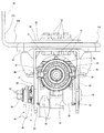
この図14〜18は、ステアリングホイール1(図7参照)の上下位置を調節する為のチルト機構と、同じく前後位置を調節する為のテレスコピック機構との両方を備えた、チルト・テレスコピック式ステアリング装置に先発明を適用した場合に就いて示している。このうちのテレスコピック機構を構成する為に、ステアリングコラム6cを、前側のインナコラム23の後部を後側のアウタコラム24の前部に内嵌して全長を伸縮可能とした、テレスコープ状のものを使用している。そして、前記ステアリングコラム6cの内径側にステアリングシャフト5bを、回転自在に支持している。
14 to 18 show a tilt / telescopic steering device having both a tilt mechanism for adjusting the vertical position of the steering wheel 1 (see FIG. 7) and a telescopic mechanism for adjusting the front / rear position. The case where the prior invention is applied is shown. In order to constitute the telescopic mechanism, the
このステアリングシャフト5bは、前側に配置した円杆状のインナシャフトの後部に設けた雄スプライン部と、後側に配置した円管状のアウタシャフト25の前部に設けた雌スプライン部とをスプライン係合させる事により、トルクの伝達を可能に、且つ、伸縮を可能に構成している。前記アウタシャフト25は、後端部を前記アウタコラム24の後端開口よりも後方に突出させた状態でこのアウタコラム24の内径側に、単列深溝型の玉軸受26等、ラジアル荷重及びスラスト荷重を支承可能な軸受により、回転のみ自在に支持している。前記ステアリングホイール1は、前記アウタシャフト25の後端部に支持固定する。このステアリングホイール1の前後位置を調節する際には、このアウタシャフト25と共に前記アウタコラム24が前後方向に変位し、前記ステアリングシャフト5b及び前記ステアリングコラム6cが伸縮する。
The steering
又、このステアリングコラム6c(を構成する前記インナコラム23)の前端部に、電動式パワーステアリング装置を構成する減速機等を収納する為のハウジング10aを、結合固定している。このハウジング10aの上面には、前記電動式パワーステアリング装置の補助動力源となる電動モータ27と、この電動モータ27への通電を制御する為の制御器28とを支持固定している。そして、前記チルト機構を構成する為に、前記ハウジング10aを車体に対し、横軸を中心とする揺動変位を可能に支持している。この為に本例の場合には、前記ハウジング10aの上部前端に支持筒29を、左右方向に設けている。そして、この支持筒29の中心孔30に挿通したボルト等の横軸により、前記ステアリングコラム6cの前端部を前記車体に対し、このステアリングコラム6cの後部を昇降させる方向の揺動変位を可能に支持する構成を採用している。
Further, a
又、前記ステアリングコラム6cの中間部乃至後部を構成する、前記アウタコラム24の前半部の内径を、弾性的に拡縮可能としている。この為に、このアウタコラム24の下面にスリット31を、軸方向に形成している。このスリット31の前端部は、このアウタコラム24の前端縁、又は、このアウタコラム24の前端寄り部分の上端部を除いた部分に形成した周方向透孔63(本発明の実施の形態の第1例を示す、図2参照)に開口させている。又、前記スリット31を幅方向両側から挟む部分に、それぞれが厚肉平板状の1対の被支持板部32、32を設けている。これら両被支持板部32、32が、前記ステアリングホイール1の位置調節時に、前記アウタコラム24と共に変位する、変位側ブラケットとして機能する。
Further, the inner diameter of the front half portion of the
図示の先発明に係る構造の場合、前記両被支持板部32、32をコラム側ブラケット33に対し、上下位置及び前後位置の調節を可能に支持している。このコラム側ブラケット33は、通常時には車体に対し支持されているが、衝突事故の際には、二次衝突の衝撃に基づいて、前方に離脱し、前記アウタコラム24の前方への変位を許容する様にしている。この為に、前記コラム側ブラケット33を車体側ブラケット11に対し、二次衝突時に加わる衝撃荷重により、前方への離脱を可能に支持している。
In the case of the structure according to the illustrated prior invention, both the supported
前記ステアリングホイール1が調節後の位置に保持されている状態で、前記両被支持板部32、32は、前記コラム側ブラケット33を構成する左右1対の支持板部34、34により強く挟持されている。これら両支持板部34、34には、前記支持筒29を車体に対し支持した横軸を中心とする部分円弧形の上下方向長孔35を、前記両被支持板部32、32には、前記アウタコラム24の軸方向に長い前後方向長孔36を、それぞれ形成している。そして、これら各長孔35、36に調節ロッド37を挿通している。この調節ロッド37の基端部(図15の右端部)に設けた頭部38は、一方(図15の右方)の支持板部34に形成した上下方向長孔に、この上下方向長孔に沿った変位のみを可能に(回転を阻止した状態で)係合させている。これに対して、前記調節ロッド37の先端部(図15の左端部)に螺着したナット39と他方(図15の左方)の支持板部34の外側面との間に、駆動側カム40と被駆動側カム41とから成るカム装置42を設けている。そして、このうちの駆動側カム40を、調節レバー43により回転駆動可能としている。
In a state where the steering wheel 1 is held at the adjusted position, the supported
前記ステアリングホイール1の位置調節を行う際には、前記調節レバー43を所定方向(下方)に回動させる事により前記駆動側カム40を回転駆動し、前記カム装置42の軸方向寸法を縮める。そして、前記被駆動側カム41と前記頭部38との、互いに対向する内側面同士の間隔を拡げ、前記両支持板部34、34が前記両被支持板部32、32を抑え付けている力を開放する。同時に、前記アウタコラム24の前部で前記インナコラム23の後部を内嵌した部分の内径を弾性的に拡げ、これらアウタコラム24の前部内周面とインナコラム23の後部外周面との当接部に作用している面圧を低下させる。この状態で、前記調節ロッド37が前記上下方向長孔35と前記前後方向長孔36との内側で変位できる範囲で、前記ステアリングホイール1の上下位置及び前後位置を調節できる。
When the position of the steering wheel 1 is adjusted, the driving
このステアリングホイール1を所望位置に移動させた後、前記調節レバー43を前記所定方向とは逆方向(上方)に回動させる事により、前記カム装置42の軸方向寸法を拡げる。これにより、前記被駆動側カム41と前記頭部38との、互いに対向する内側面同士の間隔を縮め、前記両支持板部34、34により前記両被支持板部32、32を強く抑え付ける。同時に、前記アウタコラム24の前部で前記インナコラム23の後部を内嵌した部分の内径を弾性的に縮め、これらアウタコラム24の前部内周面とインナコラム23の後部外周面との当接部に作用している面圧を高くする。この状態で、前記ステアリングホイール1の上下位置及び前後位置が調節後の位置に保持される。
After the steering wheel 1 is moved to a desired position, the axial dimension of the
尚、図示の例の場合には、前記ステアリングホイール1を調節後の位置に保持する為の保持力を高くする為に、前記両支持板部34、34の内側面と前記両被支持板部32、32の外側面との間に、それぞれ摩擦板ユニット44、44を挟持している。これら両摩擦板ユニット44、44は、前記上下方向長孔35と整合する長孔を形成した1乃至複数枚の第一摩擦板と、前記前後方向長孔36と整合する長孔を形成した1乃至複数枚の第二摩擦板とを交互に重ね合わせたもので、摩擦面積を増大させ、前記保持力を高くする役目を有する。この様な摩擦板ユニット44、44の具体的な構造及び作用に就いては、例えば特許文献4〜5に記載される等により従来から知られており、先発明並びに本発明の要旨とも関係しないので、詳しい図示並びに説明は省略する。
In the case of the illustrated example, in order to increase the holding force for holding the steering wheel 1 in the adjusted position, the inner side surfaces of the both
更に、前記コラム側ブラケット33は、前記車体側ブラケット11に対し、二次衝突の衝撃荷重により前方に離脱はするが、二次衝突が進行した状態でも、脱落しない様に支持している。前記車体側ブラケット11は、車体側に支持固定されて、二次衝突時にも前方に変位する事がないもので、鋼板等の十分な強度及び剛性を有する金属板に、プレスによる打ち抜き加工及び曲げ加工を施す事により造っている。この様な車体側ブラケット11は、両側縁部及び後端縁部を下方に折り曲げる事により曲げ剛性を向上させ、幅方向中央部に前端縁側が開口した係止切り欠き45を、この係止切り欠き45の後部を左右両側から挟む位置に1対の取付孔46、46を、それぞれ形成している。前記係止切り欠き45は、次述する係止カプセル47により覆われた、前記車体側ブラケット11の後端部近傍まで形成している。この様な車体側ブラケット11は、前記両取付孔46、46を挿通したボルト或いはスタッドにより、車体に対し支持固定される。
Further, the
上述の様な車体側ブラケット11に対して前記コラム側ブラケット33を、係止カプセル47を介して、二次衝突時に前方への離脱を可能に結合している。この係止カプセル47としては、図17に示す様な構造のものが好ましく使用できるが、図18に示す様な係止カプセル47aを使用する事もできる。このうちの図18に示した係止カプセル47aに関しては、後で説明し、先ず、図17に示した係止カプセル47を使用した場合に就いて説明する。
The
この係止カプセル47は、アルミニウム系合金、軟鋼等の金属製素材に鍛造加工等の塑性加工を施したり、アルミニウム系合金、マグネシウム系合金等の軽合金をダイキャスト成形する事により、或いは、ポリアセタール等の高強度の高機能樹脂を射出成形する事により造っている。そして、左右方向に関する幅寸法、並びに、前後方向に関する長さ寸法を、下半部に比べ上半部で大きくして、前記係止カプセル47の左右両側面及び後側面の上半部に、両側方及び後方に突出する鍔部48を設けている。この様な係止カプセル47は、下半部を前記係止切り欠き45に係合(内嵌)した状態で、前記車体側ブラケット11に対し、二次衝突時に加わる衝撃荷重に基づいて前方への離脱を可能に支持している。この為に、前記鍔部48と、前記車体側ブラケット11の一部で前記係止切り欠き45の周縁部との、互いに整合する複数箇所(図示の例では8箇所ずつ)に、それぞれ小通孔49a、49bを形成している。そして、これら各小通孔49a、49b同士の間に、それぞれ係止ピン50、50を掛け渡している。
The locking
これら各係止ピン50、50は、前記各小通孔49a、49bを整合させた状態でこれら各小通孔49a、49b内に合成樹脂を注入する(インジェクション成形する)事により、或いは、予め円柱状に成形した、合成樹脂製或いは軽合金製の素ピンを前記各小通孔49a、49a内に圧入する(軸方向に大きな力で押し込む)事により、前記各小通孔49a、49b同士の間に掛け渡す。何れの場合でも、前記各係止ピン50、50を構成する合成樹脂材料或いは軽合金材料の一部が、前記車体側ブラケット11の上下両面と、相手面である、前記鍔部48の下面及び前記コラム側ブラケット33の上面との間に入り込む。そして、これら各面同士の間に存在する隙間に拘らず、前記車体側ブラケット11に対する前記コラム側ブラケット33の取付部のがたつきを解消する。従って、前記各隙間を確実に塞ぎ、このがたつきを確実に解消する為には、前記各係止ピン50、50を、合成樹脂の射出成形(インジェクション成形)により形成する事が好ましい。尚、図17及び後述する図18には、明りょう化の為に、前記がたつきの原因となる隙間の高さを、実際よりも大きく描いている。
These locking pins 50, 50 are prepared by injecting synthetic resin into these small through
尚、前記各係止ピン50、50をインジェクション成形する場合には、溶融樹脂が前記各面同士の間の隙間に入り込んで冷却固化し、前記がたつきを解消する。これに対して、素ピンを圧入する場合には、この素ピンに加わる軸方向の力に基づいて、この素ピンの軸方向中間部で前記各隙間に対応する部分が径方向外方に拡がり、これら各隙間の存在に基づくがたつきを解消する。何れにしても、前記各小通孔49a、49b同士の間に前記各係止ピン50、50を掛け渡す事により、前記係止カプセル47を前記車体側ブラケット11に対し、二次衝突時に加わる衝撃荷重により前方への離脱を可能に支持する。
When the locking pins 50 are injection-molded, the molten resin enters the gaps between the surfaces and solidifies by cooling, thereby eliminating the rattling. On the other hand, when the element pin is press-fitted, on the basis of the axial force applied to the element pin, the portion corresponding to each of the gaps expands radially outward in the axial intermediate portion of the element pin. The rattling based on the existence of these gaps is eliminated. In any case, the locking
上述の様な係止カプセル47は前記コラム側ブラケット33に対し、複数本(図示の例では3本)のボルト51、51とナット52、52とにより、前記衝撃荷重に拘らず非分離な状態で、結合固定している。即ち、前記係止カプセル47及び前記コラム側ブラケット33の互いに整合する位置に形成した通孔を下方から挿通した、前記各ボルト51、51の先端部(上端部)で前記係止カプセル47の上面から突出した部分に、前記各ナット52、52を螺合し更に締め付ける事で、前記係止カプセル47と前記コラム側ブラケット33とを結合固定している。従って、二次衝突時に前記アウタコラム24からこのコラム側ブラケット33に伝わった前記衝撃荷重は、そのまま前記係止カプセル47に伝わり、前記各係止ピン50、50の裂断に伴ってこの係止カプセル47が前方に変位するのと同期して、前記アウタコラム24も前方に変位する。
The above-described
この様に、二次衝突時にこのアウタコラム6cと共に前方に変位する、前記係止カプセル47を係止した、前記係止切り欠き45の前後方向に関する長さL45は、この係止カプセル47の同方向の長さL47よりも十分に大きい(L45≫L47)。図示の例の場合には、前記係止切り欠き45の長さL45を、前記係止カプセル47の長さL47の2倍以上(L45≧2L47)確保している。そして、二次衝突時に前記アウタコラム24と共に前記係止カプセル47が前方に変位し切った(ステアリングホイール1から加わった衝撃荷重では、それ以上前方に変位しなくなった)状態でも、この係止カプセル47を構成する前記鍔部48の少なくとも後端部で、前記ステアリングコラム6c及び前記コラム側ブラケット33等の重量を支承可能な部分が、前記係止切り欠き45から抜け出ない様にしている。即ち、二次衝突が進行した状態でも、前記係止カプセル47の上半部の幅方向両側部分に形成した前記鍔部48のうちの後端部が、前記車体側ブラケット11の前端部の上側に位置して、前記係止カプセル47が落下するのを防止できる様にしている。
In this way, the length L 45 in the front-rear direction of the locking
上述の様に構成する、先発明に係るステアリングコラム用支持装置によれば、二次衝突時に前記ステアリングホイール1を前方に安定して変位させる為のチューニングが容易で、しかも、二次衝突が進行した状態でも前記ステアリングホイール1が過度に下方に変位する事を防止できる。
先ず、二次衝突時にステアリングホイール1を前方に安定して変位させる為のチューニングの容易化は、前記車体側ブラケット11と前記係止カプセル47とを、この車体側ブラケット11の幅方向中央部のみで係合させる事により図れる。
According to the steering column supporting device according to the present invention configured as described above, tuning for stably displacing the steering wheel 1 forward in a secondary collision is easy, and the secondary collision proceeds. Even in such a state, the steering wheel 1 can be prevented from being excessively displaced downward.
First, in order to facilitate the tuning for stably displacing the steering wheel 1 forward at the time of a secondary collision, the vehicle
即ち、前記単一の係止カプセル47を、前記アウタコラム24の直上部分に配置している為、二次衝突時に前記ステアリングホイール1から前記アウタシャフト25及び前記アウタコラム24を通じて前記係止カプセル47に伝わった衝撃荷重が、この係止カプセル47と前記車体側ブラケット11とを結合している、前記各係止ピン50、50に、ほぼ均等に加わる。要するに、前記衝撃荷重は、前記係止カプセル47のほぼ中央部に、前記アウタコラム24の軸方向に作用する。そして、この単一の係止カプセル47が、前記係止切り欠き45から前方に抜け出る方向の力が加わる。この為、この係止カプセル47と前記車体側ブラケット11とを結合している前記各係止ピン50、50が、実質的に同時に裂断する。この結果、前記コラム側ブラケット33等を介して前記係止カプセル47と結合された前記アウタコラム24の前方への変位が、中心軸を過度に傾斜させたりする事無く、安定して行われる。
That is, since the
特に、図示の例では、前記ステアリングホイール1の上下位置及び前後位置を調節する為のチルト・テレスコピック機構を設けると共に、このステアリングホイール1を調節後の位置に保持する保持力を高める為の摩擦板ユニット44、44を設置している。これらチルト・テレスコピック機構や摩擦板ユニット44、44を設ける事は、製作誤差の蓄積等により、二次衝突時の離脱荷重のばらつきを大きくする原因となり易いが、図示の例の場合には、前記単一の係止カプセル47と前記車体側ブラケット11との係合により、前記離脱荷重のばらつきを抑えられる。この結果、二次衝突時に前記ステアリングホイール1に衝突した運転者の身体に加わる衝撃を緩和する為のチューニングを適正に行って、この運転者の保護充実を図り易くなる。
In particular, in the illustrated example, there is provided a tilt / telescopic mechanism for adjusting the vertical position and the front / rear position of the steering wheel 1, and a friction plate for increasing the holding force for holding the steering wheel 1 in the adjusted position.
又、二次衝突が進行した状態でも前記ステアリングホイール1が過度に下方に変位するのを防止する事は、前記係止切り欠き45の前後方向長さL45を前記係止カプセル47の前後方向の長さL47よりも十分に大きくしている事により図れる。即ち、これら各長さL45、L47をこの様に規制している為、二次衝突が進行し、前記ステアリングホイール1と共に、前記係止カプセル47が前方に変位し切った状態でも、この係止カプセル47全体が前記係止切り欠き45から前方に抜け出る事はない。この為、二次衝突が進行した状態でも、前記アウタコラム24の支持力を確保して、このアウタコラム24及び前記アウタシャフト25を介してこのアウタコラム24に支持された前記ステアリングホイール1が、過度に下降する事を防止できる。そして、事故後もこのステアリングホイール1の操作を行い易くして、例えば、事故車両が自走可能である場合に、この事故車両を事故現場から路肩まで自走移動させる際の運転を行い易くできる。
Further, to prevent the steering wheel 1 from being excessively displaced downward even in a state in which a secondary collision has progressed, the longitudinal length L 45 of the locking
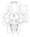
次に、図18に示した構造に就いて説明する。図17に示した構造は、前記係止カプセル47の形状が単純で、この係止カプセル47の製造コストを抑えられる他、この係止カプセル47を設置した部分の組み立て高さを低く抑えられる。この様な構造は、ステアリングコラム用支持装置の小型・軽量化を図ったり、衝撃荷重が作用する位置である、前記アウタコラム24の中心軸と、二次衝突時に離脱する部分である、前記車体側ブラケット11と前記係止カプセル47の係合部との距離を短くして、この係合部の離脱荷重を安定させる(この距離が長くなる事に伴う捩れを抑える)面から有利である。
Next, the structure shown in FIG. 18 will be described. In the structure shown in FIG. 17, the shape of the locking
これに対して、図18に示した構造は、係止ピン50、50の射出成形の容易化を図る面から有利である。即ち、図17に示した構造の場合には、前記係止ピン50、50を射出成形する際に、前記車体側ブラケット11と前記係止カプセル47と前記コラム側ブラケット33とを、前記各ボルト51、51と前記各ナット52、52とにより結合した状態で行う。これに対して図18に示した構造の場合には、前記係止ピン50、50を射出成形する為の金型に、車体側ブラケット11及び係止カプセル47aのみをセットすれば済む為、金型の小型化を図り易い。即ち、この係止カプセル47aは、左右両側面にそれぞれ係止溝53、53を形成し、これら両係止溝53、53に、前記車体側ブラケット11の係止切り欠き45の両側縁部を係合させている。この為、この車体側ブラケット11と前記係止カプセル47aとを前記各係止ピン50、50により結合してから、この係止カプセル47aをコラム側ブラケット33に対し、各ボルト51、51と各ナット52、52とにより結合固定する事ができる。
On the other hand, the structure shown in FIG. 18 is advantageous in terms of facilitating injection molding of the locking pins 50 and 50. That is, in the case of the structure shown in FIG. 17, when the locking pins 50 are injection molded, the vehicle
上述の様な先発明の構造は、二次衝突時に於ける運転者の保護充実を図る設計を容易化できる利点がある。但し、通常時に於ける運転者の操作感を向上させる為には、次の様な点を改良する事が望まれる。即ち、前記車体側ブラケット11の形状が、前記係止カプセル47を係止する為の後半部を含めて全体として平板状である為、この車体側ブラケット11の剛性を高くする面からは不利である。この剛性が低いと、この車体側ブラケット11の固有振動値が低くなり、悪路走行時等にこの車体側ブラケット11に支持された前記ステアリングコラム6cが、車体の振動に伴って共振し易くなる。そして、この様な共振が発生すると、ステアリングホイール1(図7参照)を操作する運転者に不快感を与える。
The structure of the prior invention as described above has an advantage that the design for enhancing the protection of the driver at the time of the secondary collision can be facilitated. However, in order to improve the driver's operational feeling during normal times, it is desirable to improve the following points. That is, since the shape of the vehicle
図14〜16に示した先発明に係る構造の場合、前記車体側ブラケット11の左右両側縁部及び後端縁部を下方に折り曲げて折り曲げ部54とし、この車体側ブラケット11の剛性確保を図っている。この車体側ブラケット11を構成する金属板の厚さが十分であれば、図14〜16に示した構造でも、必要とする剛性を確保できる。但し、厚さ寸法が大きな金属板に前記折り曲げ部54を曲げ形成する事は、容量の大きなプレス加工機が必要になり、製造コストが嵩む原因となる。これらの事を考慮すれば、特に厚さ寸法が大きな金属板を使用しなくても、車体側ブラケットに十分な剛性を持たせられる構造の実現が望まれる。尚、図11に示した従来構造の場合、車体側ブラケット11aを車体に対して、閉じられた断面形状を有する取付ブラケット55を介して車体に取り付ける構造を採用している為、或る程度前記車体側ブラケット11aの剛性を確保できる可能性がある。但し、形状が特殊な前記取付ブラケット55を使用する為、コスト並びに取付高さ寸法が嵩む事が避けられない。
In the case of the structure according to the previous invention shown in FIGS. 14 to 16, the left and right side edges and the rear edge of the vehicle
本発明は、上述の様な事情に鑑みて、二次衝突時にステアリングホイールを前方に安定して変位させる為のチューニングが容易で、しかも、特に厚さ寸法が大きな金属板を使用しなくても、車体側ブラケットに十分な剛性を持たせる事ができ、且つ、ステアリングホイールが過度に下降するのを防止できる構造を実現すべく発明したものである。 In view of the circumstances as described above, the present invention is easy to tune to stably displace the steering wheel forward at the time of a secondary collision, and without using a metal plate having a particularly large thickness. The present invention has been invented to realize a structure in which the vehicle body side bracket can be provided with sufficient rigidity and the steering wheel can be prevented from being lowered excessively.
本発明のステアリングコラム用支持装置は、前述の図11〜13に示した従来構造と同様に、車体側ブラケットと、係止切り欠きと、コラム側ブラケットと、係止カプセルとを備える。
このうちの車体側ブラケットは、車体側に支持固定されて、二次衝突時にも前方に変位する事がない。
又、前記係止切り欠きは、前記車体側ブラケットの幅方向中央部に形成されたもので、この車体側ブラケットの前端縁側が開口している。
又、前記コラム側ブラケットは、ステアリングコラム側に支持されて、二次衝突時にこのステアリングコラムと共に前方に変位する。
又、前記係止カプセルは、前記コラム側ブラケットに固定された状態で、両端部を前記係止切り欠きに係止すると共に、上端両側部をこの係止切り欠きの両側部分で前記車体側ブラケットの上側に位置させている。
そして、前記係止カプセルの一部を前記係止切り欠きの内側に位置させた状態で、この係止カプセルと前記車体側ブラケットとを、前記二次衝突時にこの係止カプセルに対し前方に加わる衝撃荷重に基づいて、この係止カプセルが前記車体側ブラケットに対し前方に変位可能な状態で結合している。
The steering column support device of the present invention includes a vehicle body side bracket, a locking notch, a column side bracket, and a locking capsule as in the conventional structure shown in FIGS.
Of these, the vehicle body side bracket is supported and fixed to the vehicle body side, and is not displaced forward even in a secondary collision.
The locking notch is formed at the center in the width direction of the vehicle body side bracket, and the front end edge side of the vehicle body side bracket is open.
The column side bracket is supported on the steering column side and is displaced forward together with the steering column at the time of a secondary collision.
The locking capsule is fixed to the column-side bracket, and both ends are locked to the locking notch, and both upper end side portions of the locking notch are both sides of the locking notch. It is located on the upper side.
Then, in a state where a part of the locking capsule is located inside the locking notch, the locking capsule and the vehicle body side bracket are applied forward with respect to the locking capsule at the time of the secondary collision. Based on the impact load, the locking capsule is coupled to the vehicle body side bracket in a state displaceable forward.
特に、本発明のステアリングコラム用支持装置に於いては、前記車体側ブラケットのうちで、少なくとも前記二次衝突が発生する以前の通常状態で前記係止カプセルが組み付けられている部分の左右両側縁部のうちの少なくとも一方の側縁部に、上方又は下方に向け直角に折れ曲がった取付板部を設けている。そして、この取付板部の片側面を車体側に設けられた被取付面に突き合わせた状態で、この車体に対し結合固定している。又、前記係止カプセルの上部両側面に、上下方向中間部よりも側方に突出する、前記係止切り欠きの幅寸法よりも大きな幅寸法を有する鍔部を設けている。更に、この係止切り欠きの前後方向に関する長さをこの鍔部の同方向の長さよりも大きくして、前記二次衝突時に前記ステアリングコラムと共にこの係止カプセルが前方に変位した状態でも、前記鍔部の少なくとも一部を前記車体側ブラケットの前端部の上側に位置させる。そして、二次衝突が進行した状態でも、前記係止カプセルが脱落するのを防止する。 In particular, in the steering column support device according to the present invention, left and right side edges of a portion of the vehicle body side bracket where the locking capsule is assembled in a normal state before at least the secondary collision occurs. An attachment plate portion bent at a right angle upward or downward is provided on at least one side edge portion of the portions. The mounting plate is coupled and fixed to the vehicle body in a state where one side surface of the mounting plate portion is abutted against a mounted surface provided on the vehicle body side. In addition, on both side surfaces of the upper part of the locking capsule, flanges having a width dimension larger than the width dimension of the locking notch projecting laterally from the middle part in the vertical direction are provided. Further, even when the locking capsule is displaced forward together with the steering column at the time of the secondary collision, the length in the front-rear direction of the locking notch is larger than the length in the same direction of the flange portion. At least a part of the flange is positioned above the front end of the vehicle body side bracket. And even if the secondary collision has progressed, the locking capsule is prevented from falling off.
上述の様な本発明を実施する場合に好ましくは、請求項2に記載した発明の様に、前記係止カプセルと前記車体側ブラケットとを、前記二次衝突時にこの係止カプセルに加わる衝撃荷重により裂断する、複数の結合部材により結合する。この場合に、これら各結合部材は、前記係止カプセルの上部両側面に、上下方向中間部よりも側方に突出する状態で設けられた、前記係止切り欠きの幅寸法よりも大きな幅寸法を有する鍔部に形成された小通孔と、前記車体側ブラケットの一部でこれら各小通孔に整合する部分に形成された受け入れ部との間に掛け渡す。尚、この受け入れ部としては、前記各小通孔と同様の小通孔、或は、それぞれが前記係止切り欠きの内側に開口する小切り欠きを採用できる。 Preferably, when carrying out the present invention as described above, the impact load applied to the locking capsule during the secondary collision between the locking capsule and the vehicle body side bracket, as in the invention described in claim 2. Are coupled by a plurality of coupling members that are torn by the above. In this case, each of these coupling members has a width dimension larger than the width dimension of the locking notch provided on the both side surfaces of the upper side of the locking capsule in a state of projecting laterally from the middle part in the vertical direction. It spans between the small through-hole formed in the collar part which has this, and the receiving part formed in the part which aligns with these small through-holes in a part of said vehicle body side bracket. In addition, as this receiving part, the small notch similar to each said small hole, or the small notch which each opens inside the said locking notch can be employ | adopted.
この様な請求項2に記載した発明を実施する場合に好ましくは、請求項3に記載した発明の様に、前記各結合部材を構成する、前記二次衝突に伴って裂断する材料を合成樹脂とする。又、これら各結合部材を、前記各小通孔及び前記各受け入れ部にこの合成樹脂を注入するインジェクション成形により造る。そして、この合成樹脂の一部を、前記車体側ブラケットの上下両面と、これら上下両面に対向する相手面との間に存在する隙間のうちの少なくとも一部に入り込ませる。前記各受け入れ部が小切り欠きの場合には、前記合成樹脂の一部を、前記上下両面と相手面との間の隙間に加えて、前記係止切り欠きの内周縁と前記係止カプセルの外周面との間の隙間にも入り込ませる。 When the invention described in claim 2 is carried out, it is preferable to synthesize a material that constitutes each of the coupling members and is torn along with the secondary collision as in the invention described in claim 3. Resin. Further, each of these connecting members is made by injection molding in which this synthetic resin is injected into each of the small through holes and each of the receiving portions. Then, a part of the synthetic resin is allowed to enter at least a part of a gap existing between the upper and lower surfaces of the vehicle body side bracket and the opposing surfaces facing the upper and lower surfaces. When each receiving part is a small notch, a part of the synthetic resin is added to the gap between the upper and lower surfaces and the mating surface, and the inner peripheral edge of the locking notch and the locking capsule Also enter the gap between the outer peripheral surface.
上述の様に構成する本発明のステアリングコラム用支持装置によれば、二次衝突時にステアリングホイールを前方に安定して変位させる為のチューニングが容易で、しかも、特に厚さ寸法が大きな金属板を使用しなくても、車体側ブラケットに十分な剛性を持たせる事ができて、衝撃吸収式ステアリング装置のコスト低減を図る事ができ、且つ、二次衝突後にステアリングホイールが過度に下降するのを防止できる。 According to the steering column support device of the present invention configured as described above, it is easy to tune to stably displace the steering wheel forward at the time of a secondary collision, and in particular, a metal plate having a large thickness dimension is used. Even if it is not used, the vehicle body side bracket can have sufficient rigidity, the cost of the shock absorbing steering device can be reduced, and the steering wheel can be lowered excessively after the secondary collision. Can be prevented.
先ず、二次衝突時にステアリングホイールを前方に安定して変位させる為のチューニングの容易化は、車体側ブラケットと係止カプセルとを、この車体側ブラケットの幅方向中央部のみで係合させる事により図れる。
又、車体側ブラケットに十分な剛性を持たせる事は、この車体側ブラケットのうちの係止カプセルが組み付けられている部分の側縁部に、上方又は下方に向け直角に折れ曲がった取付板部を設ける事により図れる。この様な取付板部を設ける事により、前記車体側ブラケットのうちで前記係止カプセルを組み付けた部分の曲げ剛性が高くなる。しかも、前記取付板部を車体に対し結合固定するので、この取付板部、及び、この取付板部に連続する、前記車体側ブラケットのうちで、前記係止カプセルを組み付けた部分の曲げ剛性を十分に高くできる。そして、この部分の固有振動数(共振周波数)を高くして、悪路走行時等にも、コラム側ブラケットやステアリングコラム、ステアリングシャフトを介して前記車体側ブラケットに支持されたステアリングホイールが振動する事を防止して、このステアリングホイールを操作する運転者に不快感を与える事を防止できる。
更に、係止切り欠きの前後方向に関する長さを前記係止カプセルの同方向の長さよりも十分に大きくし、この係止カプセルが前記係止切り欠きから前方に抜け出さない様にしている為、前記二次衝突が進行した状態でも前記ステアリングホイールが過度に下降する事を防止できる。そして、事故後もこのステアリングホイールの操作を行い易くして、例えば、事故車両が自走可能である場合に、この事故車両を事故現場から路肩まで自走移動させる際の運転を行い易くできる。
First, to facilitate the tuning to stably displace the steering wheel forward in the event of a secondary collision, the vehicle body side bracket and the locking capsule are engaged only at the center in the width direction of the vehicle body side bracket. I can plan.
In addition, providing the vehicle body side bracket with sufficient rigidity means that a mounting plate portion bent at a right angle upward or downward is formed on the side edge of the portion of the vehicle body side bracket where the locking capsule is assembled. It can be planned by providing. By providing such a mounting plate portion, the bending rigidity of the portion of the vehicle body side bracket where the locking capsule is assembled is increased. In addition, since the attachment plate portion is coupled and fixed to the vehicle body, the bending rigidity of the attachment plate portion and the portion of the vehicle body side bracket that is continuous with the attachment plate portion, to which the locking capsule is assembled, is increased. Can be high enough. Then, the natural frequency (resonance frequency) of this portion is increased, and the steering wheel supported by the vehicle body side bracket vibrates via the column side bracket, the steering column, and the steering shaft even when traveling on a rough road. It is possible to prevent the driver operating the steering wheel from feeling uncomfortable.
Furthermore, because the length of the locking notch in the front-rear direction is sufficiently larger than the length of the locking capsule in the same direction so that the locking capsule does not escape forward from the locking notch, Even in a state where the secondary collision has progressed, the steering wheel can be prevented from being lowered excessively. The steering wheel can be easily operated even after an accident. For example, when the accident vehicle can be self-propelled, it is possible to easily perform the operation for moving the accident vehicle from the accident site to the road shoulder.
又、請求項2、3に記載した発明の様に、前記車体側ブラケットの上下両面と相手面との間に存在する隙間のうちの少なくとも一部を、前記二次衝突に伴って裂断する材料である合成樹脂により塞げば、前記車体側ブラケットと、前記係止カプセルを支持固定したコラム側ブラケットとの結合部のがたつきをなくせる。そして、このコラム側ブラケットに対し、ステアリングコラム及びステアリングシャフトを介して支持された、ステアリングホイールががたつく事を防止して、このステアリングホイールの操作感の向上を図れる。 Further, as in the invention described in claims 2 and 3, at least a part of a gap existing between the upper and lower surfaces of the vehicle body side bracket and the mating surface is torn along with the secondary collision. If it is closed with a synthetic resin, which is a material, rattling of the joint between the vehicle body side bracket and the column side bracket that supports and fixes the locking capsule can be eliminated. The steering wheel supported by the column side bracket via the steering column and the steering shaft can be prevented from rattling, and the operational feeling of the steering wheel can be improved.
[実施の形態の第1例]
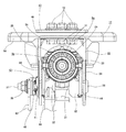
図1〜4は、本発明の実施の形態の第1例を示している。尚、本例の特徴は、車体側ブラケット11bの形状、及び、この車体側ブラケット11bを結合固定する車体56部分の構造にある。
その他の部分の構造及び作用は、前述の図14〜18に示した先発明に係る構造と同様であるから、同等部分に関する説明は、省略若しくは簡略にし、以下、本例の特徴部分、及び、前記先発明に係る構造と異なる部分を中心に説明する。
[First example of embodiment]
1 to 4 show a first example of an embodiment of the present invention. The feature of this example is the shape of the vehicle
Since the structure and operation of the other parts are the same as those of the structure according to the previous invention shown in FIGS. 14 to 18 described above, description of equivalent parts is omitted or simplified. The description will focus on the parts different from the structure according to the previous invention.
本例のステアリングコラム用支持装置に於いては、前記車体側ブラケット11bの後半部で、係止カプセル47が組み付けられている部分の左右両側縁部を、それぞれ上方に向け直角に折り曲げる事により、互いに平行な1対の取付板部57、57を設けている。一方、前記車体56の一部(ダッシュボードの下側等、ステアリングコラム6cを支持すべき部分)に、取付用凸部58を設け、この取付用凸部58の左右両側面を、1対の被取付面59、59としている。この取付用凸部58の幅Wは、前記両取付板部57、57同士の間隔Dと実質的に一致(W≒D)させている。そして、これら両取付板部57、57の上部内側面(互いに対向する側面)を、前記両被取付面59、59に突き合わせた状態で、前記車体側ブラケット11bを前記車体56に対し結合固定している。
In the steering column support device of the present example, by bending the left and right side edges of the part where the locking
この為に本例の場合には、前記両取付板部57、57の上部中央にそれぞれ取付孔60、60を設けると共に、前記取付用凸部58に、左右に貫通する貫通孔を形成している。そして、この貫通孔及び前記両取付孔60、60を挿通したボルト61とナット62とを螺合し更に締め付ける事により、前記両取付板部57、57により前記取付用凸部58を強く挟持している。尚、これら両取付板部57、57は、前記車体側ブラケット11bを構成する金属板の一部を上方に折り曲げる事により、この車体側ブラケット11bと一体に設けている。従って、この車体側ブラケット11bのうちで前記両取付板部57、57を設けた部分には、前述の図14〜16に示した先発明の構造の様な折り曲げ部54は存在しない。但し、前記両取付板部57、57から外れた部分には、前端縁部を除き、折り曲げ部54aが存在する。
For this reason, in the case of this example, mounting
上述な本例のステアリングコラム用支持装置によれば、特に厚さ寸法が大きな金属板を使用しなくても、前記車体側ブラケット11bに十分な剛性を持たせる事ができる。即ち、本例の構造の場合には、この車体側ブラケット11bのうち、係止カプセル47が組み付けられている部分である、後半部の左右両側縁部に、それぞれが上方に向け直角に折れ曲がった、1対の取付板部57、57を設けている。この様な1対の取付板部57、57を設ける事により、前記車体側ブラケット11bのうちで前記係止カプセル47を組み付けた部分、即ち、通常状態でこの係止カプセル47を設置した部分の曲げ剛性が高くなる。しかも、前記両取付板部57、57は前記車体56の取付用凸部58に対して、前記ボルト61と前記ナット62との締め付けにより、強固に結合固定している。従って、前記両取付板部57、57、及び、これら両取付板部57、57の下端縁同士の間に掛け渡される状態で存在する、前記車体側ブラケット11bのうちで、前記係止カプセル47を組み付けた、後半部分の曲げ剛性を十分に高くできる。
According to the steering column support device of the present example described above, the vehicle
そして、この後半部分の固有振動数(共振周波数)を高くして、悪路走行時等にも、コラム側ブラケット33やステアリングコラム6c、ステアリングシャフト5bを介して前記車体側ブラケット11bに支持されたステアリングホイール1(図7参照)が振動する事を防止し、このステアリングホイール1を操作する運転者に不快感を与える事を防止できる。
その他の部分の構成及び作用は、前述の図14〜17に示した先発明に係る構造と同様であるから、同等部分には同一符号を付して、重複する説明を省略する。
Then, the natural frequency (resonance frequency) of the latter half is increased, and the vehicle
Since the configuration and operation of the other parts are the same as those of the structure according to the previous invention shown in FIGS. 14 to 17 described above, the same parts are denoted by the same reference numerals, and redundant description is omitted.
[実施の形態の第2例]
図5は、本発明の実施の形態の第2例を示している。本例の場合には、車体側ブラケット11cの片側縁(図5の左側縁)から延出した延出部64の先端部を下方に向け直角に折り曲げる事により、取付板部57aとしている。これに対して、前記車体側ブラケット11cの他側縁(図5の右側縁)は、前述の図14〜17に示した先発明に係る構造と同様に、折り曲げ部54を形成したのみとしている。
[Second Example of Embodiment]
FIG. 5 shows a second example of the embodiment of the present invention. In the case of this example, the mounting
上述の様な車体側ブラケット11cを支持固定すべき車体56a側には、係止カプセル47とコラム側ブラケット33とを結合固定する為のボルト51、51及びナット52、52との干渉を防止する為の凹部65を左右両側から挟む状態で、下向被取付面66と、側方被取付面67とを設けている。そして、前記取付板部57aの外側面をこの側方被取付面67に、前記車体側ブラケット11cの他側縁寄り部分の上面を前記下向被取付面66に、それぞれ突き合わせた状態で、それぞれボルト61a、61aにより、結合固定している。
その他の部分の構成及び作用は、上述した実施の形態の第1例と同様であるから、同等部分に関する図示並びに説明は省略する。
On the
Since the configuration and operation of the other parts are the same as in the first example of the above-described embodiment, illustration and description regarding the equivalent parts are omitted.
[実施の形態の第3例]
図6は、本発明の実施の形態の第3例を示している。本例の場合には、車体側ブラケット11dの片側縁(図6の左側縁)から延出した延出部64aの先端部を上方に向け直角に折り曲げる事により、取付板部57bとしている。これに対して、前記車体側ブラケット11dの他側縁(図6の右側縁)は、前述の図14〜17に示した先発明に係る構造と同様に、折り曲げ部54を形成したのみとしている。
車体側の形状に就いても、前記車体側ブラケット11dの形状に合わせたものとしている。その他の部分の構成及び作用は、上述した実施の形態の第1例と同様であるから、同等部分に関する図示並びに説明は省略する。
[Third example of embodiment]
FIG. 6 shows a third example of the embodiment of the present invention. In the case of this example, the
The shape on the vehicle body side is also adapted to the shape of the vehicle
上述した実施の形態は、本発明を、ステアリングホイールの上下位置を調節する為のチルト機構と、同じく前後位置を調節する為のテレスコピック機構との両方を備えたステアリングコラム用支持装置に適用した場合に就いて説明した。但し、本発明は、チルト機構のみ、又はテレスコピック機構のみを備えたステアリングコラム用支持装置、更には、これら両機構を何れも備えていない、ステアリングホイールの位置固定式のステアリングコラム用支持装置で実施する事もできる。 In the embodiment described above, the present invention is applied to a steering column support device having both a tilt mechanism for adjusting the vertical position of the steering wheel and a telescopic mechanism for adjusting the front-back position. Explained. However, the present invention is implemented by a steering column support device having only a tilt mechanism or only a telescopic mechanism, and further by a steering column support device having a fixed steering wheel position that does not have both of these mechanisms. You can also do it.
又、本発明を実施するのに、車体側ブラケットに対して係止カプセルを結合するには、必ずしも、係止ピンを圧入したり、合成樹脂をインジェクション成形する必要はない。例えば、車体側ブラケットに形成した係止切り欠きに、係止カプセルの係止溝部分を圧入して、これら車体側ブラケットと係止カプセルとを結合する事もできる。 In order to implement the present invention, it is not always necessary to press-fit a locking pin or injection-mold a synthetic resin in order to connect the locking capsule to the vehicle body side bracket. For example, a locking groove portion of the locking capsule can be press-fitted into a locking notch formed in the vehicle body side bracket, and the vehicle body side bracket and the locking capsule can be coupled.
更に、本発明を実施する場合に、二次衝突時に前記係止カプセルと共に前方に変位する部分と、同じく変位しない部分との間に、塑性変形する事で、前記二次衝突時に加わる衝撃エネルギを吸収しつつ前記係止カプセルの前方への変位を許容する、エネルギ吸収部材を設ける。この様なエネルギ吸収部材としては、特許文献1〜3に記載される等により従来から知られている、種々の構造のものを採用可能であるが、好ましくは、幅方向中央部に設置できるものを採用する。
尚、車体側ブラケットの側縁部に設ける取付板部の、この車体側ブラケットの中央部分に対する折り曲げ角度は、例えば45度、135度、270度等、1〜179度、181〜359度の範囲の値であれば、或る程度の剛性向上を図れる。但し、本発明の様に、直角(90度)折り曲げる構造に比べれば、剛性向上効果が劣る事は避けられない。
Further, when the present invention is implemented, the impact energy applied at the time of the secondary collision is reduced by plastically deforming between the portion that is displaced forward together with the locking capsule at the time of the secondary collision and the portion that is also not displaced. An energy absorbing member is provided that allows forward displacement of the locking capsule while absorbing. As such an energy absorbing member, those having various structures which are conventionally known as described in Patent Documents 1 to 3, etc. can be adopted, but preferably those which can be installed in the center in the width direction. Is adopted.
The bending angle of the mounting plate portion provided on the side edge portion of the vehicle body side bracket with respect to the central portion of the vehicle body side bracket is in the range of, for example, 45 degrees, 135 degrees, 270 degrees, 1 to 179 degrees, 181 to 359 degrees. With this value, a certain degree of rigidity can be improved. However, it is inevitable that the rigidity improvement effect is inferior to a structure that bends at right angles (90 degrees) as in the present invention.
1 ステアリングホイール
2 ステアリングギヤユニット
3 入力軸
4 タイロッド
5、5a、5b ステアリングシャフト
6、6a、6b、6c ステアリングコラム
7 自在継手
8 中間シャフト
9 自在継手
10、10a ハウジング
11、11a、11b、11c、11d 車体側ブラケット
12、12a コラム側ブラケット
13 ハウジング側ブラケット
14a、14b 取付板部
15a、15b 切り欠き
16a、16b 滑り板
17 エネルギ吸収部材
18 係止切り欠き
19 係止カプセル
20、20a 係止溝
21a、21b 係止孔
22 係止ピン
23 インナコラム
24 アウタコラム
25 アウタシャフト
26 玉軸受
27 電動モータ
28 制御器
29 支持筒
30 中心孔
31 スリット
32 被支持板部
33 コラム側ブラケット
34 支持板部
35 上下方向長孔
36 前後方向長孔
37 調節ロッド
38 頭部
39 ナット
40 駆動側カム
41 被駆動側カム
42 カム装置
43 調節レバー
44 摩擦板ユニット
45 係止切り欠き
46 取付孔
47、47a、47b、47c 係止カプセル
48、48a、48b 鍔部
49a、49b、49c 小通孔
50 係止ピン
51 ボルト
52 ナット
53 係止溝
54、54a 折り曲げ部
55 取付ブラケット
56、56a 車体
57、57a、57b 取付板部
58 取付用凸部
59 被取付面
60 取付孔
61、61a ボルト
62 ナット
63 周方向透孔
64、64a 延出部
65 凹部
66 下向被取付面
67 側方被取付面
DESCRIPTION OF SYMBOLS 1 Steering wheel 2 Steering gear unit 3 Input shaft 4 Tie rod 5, 5a, 5b Steering shaft 6, 6a, 6b, 6c Steering column 7 Universal joint 8 Intermediate shaft 9 Universal joint 10, 10a Housing 11, 11a, 11b, 11c, 11d Car body side bracket 12, 12a Column side bracket 13 Housing side bracket 14a, 14b Mounting plate 15a, 15b Notch 16a, 16b Sliding plate 17 Energy absorbing member 18 Locking notch 19 Locking capsule 20, 20a Locking groove 21a, 21b Locking hole 22 Locking pin 23 Inner column 24 Outer column 25 Outer shaft 26 Ball bearing 27 Electric motor 28 Controller 29 Support cylinder 30 Center hole 31 Slit 32 Supported plate part 33 Column side bracket Reference Signs List 4 Support plate 35 Longitudinal slot 36 Longitudinal slot 37 Adjustment rod 38 Head 39 Nut 40 Driving cam 41 Driven cam 42 Cam device 43 Adjustment lever 44 Friction plate unit 45 Locking notch 46 Mounting hole 47 47a, 47b, 47c Locking capsule 48, 48a, 48b Gutter part 49a, 49b, 49c Small hole 50 Locking pin 51 Bolt 52 Nut 53 Locking groove 54, 54a Bending part 55 Mounting bracket 56, 56a Car body 57, 57a, 57b Mounting plate portion 58 Mounting convex portion 59 Mounted surface 60 Mounting hole 61, 61a Bolt 62 Nut 63 Circumferential through-hole 64, 64a Extension portion 65 Recessed portion 66 Downward mounted surface 67 Side mounted surface
Claims (3)
Priority Applications (5)
| Application Number | Priority Date | Filing Date | Title |
|---|---|---|---|
| JP2010252135A JP5553005B2 (en) | 2010-11-10 | 2010-11-10 | Steering column support device |
| PCT/JP2011/073504 WO2012060193A1 (en) | 2010-11-02 | 2011-10-13 | Steering column assist device |
| EP11837844.7A EP2636573B1 (en) | 2010-11-02 | 2011-10-13 | Steering column assist device |
| CN201180002110.6A CN102596689B (en) | 2010-11-02 | 2011-10-13 | Steering column assist device |
| US13/379,550 US8528937B2 (en) | 2010-11-02 | 2011-10-13 | Steering column support apparatus |
Applications Claiming Priority (1)
| Application Number | Priority Date | Filing Date | Title |
|---|---|---|---|
| JP2010252135A JP5553005B2 (en) | 2010-11-10 | 2010-11-10 | Steering column support device |
Related Child Applications (1)
| Application Number | Title | Priority Date | Filing Date |
|---|---|---|---|
| JP2013241419A Division JP5737369B2 (en) | 2013-11-22 | 2013-11-22 | Steering column support device |
Publications (2)
| Publication Number | Publication Date |
|---|---|
| JP2012101687A JP2012101687A (en) | 2012-05-31 |
| JP5553005B2 true JP5553005B2 (en) | 2014-07-16 |
Family
ID=46392632
Family Applications (1)
| Application Number | Title | Priority Date | Filing Date |
|---|---|---|---|
| JP2010252135A Active JP5553005B2 (en) | 2010-11-02 | 2010-11-10 | Steering column support device |
Country Status (1)
| Country | Link |
|---|---|
| JP (1) | JP5553005B2 (en) |
Families Citing this family (4)
| Publication number | Priority date | Publication date | Assignee | Title |
|---|---|---|---|---|
| JP5375806B2 (en) * | 2010-11-29 | 2013-12-25 | 日本精工株式会社 | Steering column support device and method for manufacturing locking capsule for steering column support device |
| JP5375870B2 (en) * | 2010-11-15 | 2013-12-25 | 日本精工株式会社 | Steering column support device |
| JP5737369B2 (en) * | 2013-11-22 | 2015-06-17 | 日本精工株式会社 | Steering column support device |
| KR102101663B1 (en) * | 2014-11-26 | 2020-06-01 | 남양넥스모 주식회사 | Impact-absorbtion structure of steering column for vehicle |
Family Cites Families (3)
| Publication number | Priority date | Publication date | Assignee | Title |
|---|---|---|---|---|
| JPS51119231U (en) * | 1975-03-24 | 1976-09-28 | ||
| JP2005067340A (en) * | 2003-08-22 | 2005-03-17 | Nsk Ltd | Steering column |
| JP2008006840A (en) * | 2006-06-27 | 2008-01-17 | Fuji Kiko Co Ltd | Steering column device |
-
2010
- 2010-11-10 JP JP2010252135A patent/JP5553005B2/en active Active
Also Published As
| Publication number | Publication date |
|---|---|
| JP2012101687A (en) | 2012-05-31 |
Similar Documents
| Publication | Publication Date | Title |
|---|---|---|
| WO2012049908A1 (en) | Support device for steering column | |
| WO2012053319A1 (en) | Steering column support device and assembly method of same | |
| WO2012049920A1 (en) | Automobile steering device | |
| JP5553005B2 (en) | Steering column support device | |
| JP5327188B2 (en) | Method for assembling support device for steering column | |
| JP5327180B2 (en) | Steering column support device | |
| JP5327179B2 (en) | Steering column support device | |
| JP5553010B2 (en) | Steering column support device | |
| JP5327202B2 (en) | Steering column support device | |
| JP5737369B2 (en) | Steering column support device | |
| JP5408181B2 (en) | Steering column support device and manufacturing method thereof | |
| JP5327189B2 (en) | Steering column support device and assembly method thereof | |
| JP5327181B2 (en) | Automotive steering device | |
| JP5737370B2 (en) | Steering column support device | |
| JP5327191B2 (en) | Steering column support device | |
| JP5327193B2 (en) | Steering column support device | |
| JP5397359B2 (en) | Steering column support device | |
| JP5553007B2 (en) | Steering column support device | |
| JP5327208B2 (en) | Steering column support device | |
| JP5327192B2 (en) | Steering column support device | |
| JP5327186B2 (en) | Steering column support device | |
| JP5327271B2 (en) | Steering column support device | |
| JP5605494B2 (en) | Steering column support device | |
| JP5327185B2 (en) | Automotive steering device | |
| JP5375806B2 (en) | Steering column support device and method for manufacturing locking capsule for steering column support device |
Legal Events
| Date | Code | Title | Description |
|---|---|---|---|
| A131 | Notification of reasons for refusal |
Free format text: JAPANESE INTERMEDIATE CODE: A131 Effective date: 20130924 |
|
| TRDD | Decision of grant or rejection written | ||
| A01 | Written decision to grant a patent or to grant a registration (utility model) |
Free format text: JAPANESE INTERMEDIATE CODE: A01 Effective date: 20140430 |
|
| A61 | First payment of annual fees (during grant procedure) |
Free format text: JAPANESE INTERMEDIATE CODE: A61 Effective date: 20140513 |
|
| R150 | Certificate of patent or registration of utility model |
Ref document number: 5553005 Country of ref document: JP Free format text: JAPANESE INTERMEDIATE CODE: R150 |