WO2020085043A1 - Dispositif d'ouverture/fermeture de porte et charnière - Google Patents
Dispositif d'ouverture/fermeture de porte et charnière Download PDFInfo
- Publication number
- WO2020085043A1 WO2020085043A1 PCT/JP2019/039266 JP2019039266W WO2020085043A1 WO 2020085043 A1 WO2020085043 A1 WO 2020085043A1 JP 2019039266 W JP2019039266 W JP 2019039266W WO 2020085043 A1 WO2020085043 A1 WO 2020085043A1
- Authority
- WO
- WIPO (PCT)
- Prior art keywords
- door
- link
- main arm
- side member
- main
- Prior art date
Links
Images


Classifications
-
- E—FIXED CONSTRUCTIONS
- E05—LOCKS; KEYS; WINDOW OR DOOR FITTINGS; SAFES
- E05D—HINGES OR SUSPENSION DEVICES FOR DOORS, WINDOWS OR WINGS
- E05D15/00—Suspension arrangements for wings
- E05D15/28—Suspension arrangements for wings supported on arms movable in horizontal plane
- E05D15/32—Suspension arrangements for wings supported on arms movable in horizontal plane with two pairs of pivoted arms
- E05D15/34—Suspension arrangements for wings supported on arms movable in horizontal plane with two pairs of pivoted arms with wings opening parallel to themselves
-
- E—FIXED CONSTRUCTIONS
- E05—LOCKS; KEYS; WINDOW OR DOOR FITTINGS; SAFES
- E05D—HINGES OR SUSPENSION DEVICES FOR DOORS, WINDOWS OR WINGS
- E05D3/00—Hinges with pins
- E05D3/06—Hinges with pins with two or more pins
-
- E—FIXED CONSTRUCTIONS
- E06—DOORS, WINDOWS, SHUTTERS, OR ROLLER BLINDS IN GENERAL; LADDERS
- E06B—FIXED OR MOVABLE CLOSURES FOR OPENINGS IN BUILDINGS, VEHICLES, FENCES OR LIKE ENCLOSURES IN GENERAL, e.g. DOORS, WINDOWS, BLINDS, GATES
- E06B7/00—Special arrangements or measures in connection with doors or windows
- E06B7/28—Other arrangements on doors or windows, e.g. door-plates, windows adapted to carry plants, hooks for window cleaners
- E06B7/36—Finger guards or other measures preventing harmful access between the door and the door frame
- E06B7/367—Finger guards or other measures preventing harmful access between the door and the door frame by covering the gap between the door and the door frame at the hinge side
-
- E—FIXED CONSTRUCTIONS
- E05—LOCKS; KEYS; WINDOW OR DOOR FITTINGS; SAFES
- E05D—HINGES OR SUSPENSION DEVICES FOR DOORS, WINDOWS OR WINGS
- E05D11/00—Additional features or accessories of hinges
- E05D11/10—Devices for preventing movement between relatively-movable hinge parts
- E05D11/1007—Devices for preventing movement between relatively-movable hinge parts with positive locking
-
- E—FIXED CONSTRUCTIONS
- E05—LOCKS; KEYS; WINDOW OR DOOR FITTINGS; SAFES
- E05D—HINGES OR SUSPENSION DEVICES FOR DOORS, WINDOWS OR WINGS
- E05D3/00—Hinges with pins
- E05D3/06—Hinges with pins with two or more pins
- E05D3/14—Hinges with pins with two or more pins with four parallel pins and two arms
-
- E—FIXED CONSTRUCTIONS
- E05—LOCKS; KEYS; WINDOW OR DOOR FITTINGS; SAFES
- E05Y—INDEXING SCHEME RELATING TO HINGES OR OTHER SUSPENSION DEVICES FOR DOORS, WINDOWS OR WINGS AND DEVICES FOR MOVING WINGS INTO OPEN OR CLOSED POSITION, CHECKS FOR WINGS AND WING FITTINGS NOT OTHERWISE PROVIDED FOR, CONCERNED WITH THE FUNCTIONING OF THE WING
- E05Y2201/00—Constructional elements; Accessories therefore
- E05Y2201/60—Suspension or transmission members; Accessories therefore
- E05Y2201/622—Suspension or transmission members elements
- E05Y2201/624—Arms
-
- E—FIXED CONSTRUCTIONS
- E05—LOCKS; KEYS; WINDOW OR DOOR FITTINGS; SAFES
- E05Y—INDEXING SCHEME RELATING TO HINGES OR OTHER SUSPENSION DEVICES FOR DOORS, WINDOWS OR WINGS AND DEVICES FOR MOVING WINGS INTO OPEN OR CLOSED POSITION, CHECKS FOR WINGS AND WING FITTINGS NOT OTHERWISE PROVIDED FOR, CONCERNED WITH THE FUNCTIONING OF THE WING
- E05Y2900/00—Application of doors, windows, wings or fittings thereof
- E05Y2900/20—Application of doors, windows, wings or fittings thereof for furnitures, e.g. cabinets
Definitions
- the present invention relates to a door opening / closing device and a hinge for moving a door in parallel between a closed position and an open position.
- the applicant has proposed the door opening / closing device shown in FIG. 11 as this kind of door opening / closing device (see Patent Document 1).
- the door opening / closing device includes a pair of hinges 51a and 51b and a connecting bar 52 connected to the pair of hinges 51a and 51b.
- each of the hinges 51a and 51b includes a main body side member 55 attached to the inner surface of the main body 53, a door side member 56 attached to the back surface of the door 54, a main body side member 55 and a door side member 56.
- a main arm 58 that is rotatably connected, a first link 57 that is rotatably connected to the main body side member 55 and the door side member 56, and a first link rotatably connected to the main body side member 55 and the door side member 56. 2 links 59, and.
- the three first axes 58a, 57a, 59a which are the rotation centers of the main arm 58, the first link 57, and the second link 59 with respect to the main body side member 55, are arranged at the vertices of a triangle when viewed in the axial direction.
- the three second shafts 58b, 57b, 59b which are the rotation centers of the main arm 58, the first link 57, and the second link 59 with respect to the door-side member 56, are arranged at the vertices of a triangle when viewed in the axial direction.
- the main body side member 55, the door side member 56, the main arm 58, and the first link 57 constitute a mechanical parallel link mechanism (also called a parallel crank mechanism). Therefore, the door 54 moves in parallel between the closed position and the open position. However, if only the main body side member 55, the door side member 56, the main arm 58, and the first link 57 are used, a thought may occur when the door 54 is opened and closed, and the mechanism becomes unstable. Therefore, the second link 59 is added to prevent the mechanism from becoming unstable.
- the main arm 58 has a bent portion 58c. This is for preventing the main arm 58 from interfering with the main body 53 or an adjacent door (not shown) at the open position of the door 54.
- a connecting bar 52 is connected to the main arms 58 of the pair of hinges 51a and 51b. This is because even if the door 54 is heavy, the pair of hinges 51a and 51b are interlocked to stably open and close the door 54.
- the connecting bar 52 is attached to the main body 53 side of the main arm 58 and near the bent portion 58c of the main arm 58. Since the connecting bar 52 passes from the top to the bottom of the main body 53, the connecting bar 52 interferes with the storage, and there is a problem that the storage space of the main body 53 becomes narrow.
- the present invention has been made in view of the above problems, and an object of the present invention is to provide a door opening / closing device that can widen the storage space of the main body.
- one aspect of the present invention includes at least two hinges and a connecting bar connected to the at least two hinges, and each hinge is a main body side member attached to an inner surface of a main body.
- a door side member attached to the back surface of the door, a main arm rotatably connected to the main body side member and the door side member, and a main arm rotatably connected to the main body side member and the door side member.
- 1 link, and a second link rotatably connected to the main body side member and the door side member, of the rotation of the main arm, the first link and the second link with respect to the main body side member.
- the three first axes that are the centers are arranged at the vertices of a triangle in the axial direction
- the three second axes that are the centers of rotation of the main arm, the first link, and the second link with respect to the door-side member are The axial view
- the main arm has a bent portion, and the door is translated in parallel between a closed position and an open position, the connecting bar is on the door side of the main arm.
- the center of the connecting bar in the width direction is defined by the first axis of the main arm and the second axis of the main arm.
- the door opening / closing device is arranged closer to the second shaft than the center of the door.
- Another aspect of the present invention is a main body side member attached to an inner surface of a main body, a door side member attached to a back surface of a door, a main arm rotatably connected to the main body side member and the door side member, A first link rotatably connected to the main body side member and the door side member; and a second link rotatably connected to the main body side member and the door side member, the main body side member With respect to the main arm, the first links and the three first axes that are the centers of rotation of the second links are arranged at the vertices of a triangle in the axial direction, and the main arm with respect to the door side member, the first link And three second axes that are the centers of rotation of the second links are arranged at the apexes of a triangle in the axial direction, the main arm has a bent portion, and the door is between the closed position and the open position.
- a center is a hinge arranged closer to the second shaft than a center between the first shaft of the main arm and the second shaft of the main arm.
- the connecting bar can be brought close to the back surface of the door in the closed position. Therefore, the storage space of the main body can be widened.
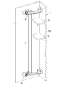
- FIG. 1 is a front perspective view of a cabinet using a door opening / closing device according to an embodiment of the present invention
- FIG. 1A is a door closed position
- FIG. 1B is an intermediate position of the door
- FIG. 2 (a) shows the door closed position
- FIG. 2 (b) shows the door intermediate position
- FIG. 2 (c) shows the door open position
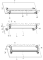
- FIG.3 (a) shows the perspective view of the hinge seen from the main body side
- FIG.3 (b) shows the perspective view of the hinge seen from the door side
- FIG.3 (a) shows the perspective view of the hinge seen from the main body side
- FIG.3 (b) shows the perspective view of the hinge seen from the door side
- FIG.3 (a) shows the perspective view of the hinge seen from the main body side
- FIG.3 (b) shows the perspective view of the hinge seen from the door side
- FIG.3 (a) shows the perspective view of the hinge seen from the main body side
- FIG. 5 is a perspective view of the main arm of the present embodiment (FIG. 5A shows a state in which the assist arm is incorporated in the arm body, and FIG. 5B shows a state in which the assist arm is removed from the arm body).
- FIG. 6 (a) is a plan view
- FIG. 6 (b) is a right side view
- FIG. 6 (c) is a bottom view
- FIG. 6 (d) is a left side view.
- FIG. 7 (a) is an AA sectional view of FIG. 6 (b)
- FIG. 7 (b) is a BB sectional view of FIG. 6 (b). ).
- FIG. 7 (a) is an AA sectional view of FIG. 6 (b)
- FIG. 7 (b) is a BB sectional view of FIG. 6 (b).
- FIG. 8 is a plan view of the door opening / closing device of the present embodiment (FIG. 8A shows a door closed position, FIG. 8B shows an intermediate position of the door, and FIG. 8C shows an open position of the door). It is a top view of the door opening and closing device of this embodiment. It is a rear side perspective view of the cabinet which attached the shelf. It is a perspective view of the conventional door opening and closing device.
- FIG. 12 is a plan view of a hinge of a conventional door opening / closing device (FIG. 12 (a) shows a door closed position, and FIG. 12 (b) shows a door open position).
- the door opening / closing device of the embodiment of the present invention will be described in detail below with reference to the accompanying drawings.
- the door opening / closing device of the present invention can be embodied in various forms, and is not limited to the embodiments described in the present specification. This embodiment is provided with the intention of making it possible for those skilled in the art to fully understand the scope of the invention by sufficiently disclosing the specification.
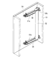
- FIG. 1 is a front perspective view of a cabinet using a door opening / closing device 1 according to an embodiment of the present invention (the door 4 is indicated by a chain double-dashed line), and FIG. 2 is a rear perspective view of the cabinet (of the main body 5). A part is shown by a broken line).
- the configuration of the door opening / closing device 1 will be described using the direction when the door 4 is viewed from the front, that is, the front-back, up-down, left-right directions shown in the drawing.
- the arrangement of the door opening / closing device 1 is not limited to this.
- FIG. 1A shows the closed position of the door 4
- FIG. 1B shows the intermediate position of the door 4
- FIG. 1C shows the opened position of the door 4.
- Reference numeral 2a is an upper hinge
- 2b is a lower hinge
- 3 is a connecting bar that connects the hinges 2a and 2b.
- the door opening / closing device 1 includes a pair of hinges 2a and 2b and a connecting bar 3 connected to the pair of hinges 2a and 2b.
- the hinge 2 a is a main body side member 11 attached to the inner surface of the side plate 5 a of the main body 5, a door side member 12 attached to the back surface of the door 4, and a main body side member 11 and a main body side member 12 rotatably connected to the door side member 12.
- the main arm 13, the first link 14, and the second link 15 have bent portions and are bent in a V shape. This is to prevent the door 4 from interfering with the side plate 5a of the main body 5 or an adjacent door (not shown) at the open position as shown in FIG. 2C.
- the hinge 2a and the hinge 2b are the same or are vertically symmetrical. Only the structure of the hinge 2a will be described below, and the description of the hinge 2b will be omitted.
- FIG. 3A shows a perspective view of the hinge 2a viewed from the main body 5 side
- FIG. 3B shows a perspective view of the hinge 2a viewed from the door 4 side.
- the first link 14 is arranged on one side (upper side) of the main arm 13 in the axial direction (vertical direction in FIG. 3A) so as to be displaced from the main arm 13.
- the second link 15 is arranged on the other side (lower side) of the main arm 13 in the axial direction (up and down direction) so as to be displaced from the main arm 13.
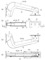
- FIG. 4 shows an exploded perspective view of the hinge.
- Reference numeral 11 is a main body side member
- 12 is a door side member
- 13 is a main arm
- 14 is a first link
- 15 is a second link.
- One end of the main arm 13 is rotatably connected to the main body side member 11 about the first shaft 13a.
- the other end of the main arm 13 is rotatably connected to the door member 12 about the second shaft 13b.
- One end of the first link 14 is rotatably connected to the body-side member 11 about the first shaft 14a.
- the other end of the first link 14 is rotatably connected to the door-side member 12 about the second shaft 14b.
- one end of the second link 15 is rotatably connected to the main body side member 11 about the first shaft 15a.
- the other end of the second link 15 is rotatably connected to the door-side member 12 about the second shaft 15b.
- the three first shafts 13a, 14a, 15a are arranged at the vertices of a triangle when viewed in the axial direction.
- the three second shafts 13b, 14b, 15b are also arranged at the vertices of a triangle when viewed in the axial direction.
- the triangle t1 (see FIG. 8A) formed by the first shafts 13a, 14a, 15a and the second shafts 13b, 14b, 15b are formed.
- the triangle t2 (see FIG. 8A) remains parallel to the door 4, and the door 4 translates between the closed position and the open position.
- the main body side member 11 includes a plate 21 fixed to the main body 5 by a fastening member such as a screw, and a bracket 22 which is fixed to the plate 21 by a fastening member such as a screw so that the front-rear position can be adjusted.
- the bracket 22 has a U-shaped cross section. A pair of side plates 22a and 22b of the bracket 22 facing each other protrude from the slit 21a of the plate 21. A hole into which the first shaft 13a of the main arm 13 is inserted is formed in each of the side plates 22a and 22b.
- a hole into which the first shaft 14a of the first link 14 is inserted is formed in the side plate 22a.
- a hole into which the first shaft 15a of the second link 15 is inserted is formed in the side plate 22b.
- the main arm 13 is arranged between the pair of side plates 22a and 22b.
- the first link 14 and the second link 15 are arranged outside the pair of side plates 22a and 22b in the axial direction.
- the front / rear position of the door 4 can be adjusted.
- the washer cover 23 (see FIG. 7A) is attached to the main body side member 11.
- the door-side member 12 is fixed to the plate 4 by a fastening member such as a screw
- the plate 24 is fixed to the plate 24 by a fastening member such as a screw so that the left-right position and the vertical position can be adjusted.
- the bracket 25 includes an angle adjustment plate 26 that is fixed to the bracket 25 by a fastening member such as a screw so that the inclination can be adjusted, and a cam 27 that is fixed to the angle adjustment plate 26 by a fastening member such as a screw.
- the bracket 25, the angle adjusting plate 26, and the cam 27 are all formed in a U-shaped cross section.
- the side plate 26a and the side plate 26b of the angle adjusting plate 26 are formed with holes into which the second shaft 13b of the main arm 13 is inserted.
- a hole into which the second shaft 14b of the first link 14 is inserted is formed in the side plate 26a.
- a hole into which the second shaft 15b of the second link 15 is inserted is formed in the side plate 26b.
- the main arm 13 is arranged between the pair of side plates 26 a and 26 b of the angle adjusting plate 26.
- the first link 14 and the second link 15 are arranged outside the pair of side plates of the bracket 25 in the axial direction.
- the horizontal and vertical positions of the bracket 25 with respect to the plate 24 By adjusting the horizontal and vertical positions of the bracket 25 with respect to the plate 24, the horizontal and vertical positions of the door 4 can be adjusted.
- the inclination of the angle adjusting plate 26 with respect to the bracket 25 By adjusting the inclination of the door 4 can be adjusted.
- the washer cover 28 (see FIG. 7A) is attached to the door-side member 12.
- the main arm 13 includes an arm body 31, an assist arm 32, a catch mechanism 33, and a damper mechanism 34.
- the arm body 31 is V-shaped and has a straight short side 31c and a straight long side 31b with the bent portion 31a as a boundary.
- the long side portion 31b of the arm body 31 has a U-shaped cross section, and has a pair of side plates 31b1 facing each other and a connecting plate 31b2 connecting the pair of side plates 31b1.
- An attachment portion 31d to which the connecting bar 3 is attached is integrally formed with the pair of side plates 31b1 of the long side portions 31b.
- the arm body 31 is manufactured by pressing a metal plate.
- the assist arm 32 has a U-shaped cross section, and has a pair of side plates 32a facing each other and a connecting plate 32b connecting the pair of side plates 32a.
- the assist arm 32 is manufactured by pressing a metal plate.
- the main arm 13 is formed in a tubular shape having a quadrangular cross section.
- a substantially L-shaped resin spacer 36 is inserted between the pair of side plates of the short side portion 31c of the arm body 31.
- the assist arm 32 and the spacer 36 are fixed to the arm body 31 with screws.
- the assist arm 32 and the spacer 36 improve the strength of the main arm 13.
- the spacer 36 is formed with a hole 36a into which the damper mechanism 34 is inserted.
- the damper mechanism 34 includes a linear damper 38 and a damper holder 37.
- the damper holder 37 has a bottomed tubular shape.
- a linear damper 38 is housed in the damper holder 37.
- a damper stopper 39 is attached to the main body side member 11. When the door 4 is closed to the vicinity of the closed position, the damper holder 37 hits the damper stopper 39 and a damper force is generated.
- a catch mechanism 33 is incorporated in a cylindrical space between the arm body 31 and the assist arm 32.
- the catch mechanism 33 includes a compression spring 41, a spring case 42, and a roller 43.
- the spring case 42 is provided on the main arm 13 so as to be movable in the length direction.
- a roller 43 is rotatably provided on the spring case 42.
- the compression spring 41 biases the roller 43 against the cam 27 of the door-side member 12.
- FIG. 7A when the door 4 is closed to the vicinity of the closed position, the roller 43 fits into the concave portion of the cam 27 and the door 4 is automatically closed.
- the roller 43 contacts the arc surface of the cam 27, an arbitrary opening angle of the door 4 is maintained.
- the first link 14 is V-shaped, and has a straight short side 14e and a straight long side 14d with the bent portion 14c interposed therebetween.
- the first link 14 has a plate shape.
- the second link 15 is also V-shaped, and has a straight short side 15e and a straight long side 15d with the bent portion 15c interposed therebetween.
- the second link 15 is also plate-shaped.
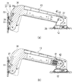
- the finger pinch prevention cover 41 is V-shaped and includes an upper cover 41a and a lower cover 41b. Similar to the main arm 13, each of the upper cover 41a and the lower cover 41b has a straight long side and a straight short side with the bent portion as a boundary.
- the upper cover 41a is attached to the upper part of the main arm 13.
- the lower cover 41b is attached to the lower part of the main arm 13.
- the upper cover 41a and the lower cover 41b enclose the main arm 13.
- Holes 42a and 42b through which the first shaft 13a and the second shaft 13b pass are formed in the upper cover 41a and the lower cover 41b.
- 43a and 43b are colors.
- the width of each of the upper cover 41 a and the lower cover 41 b (width in the direction orthogonal to the length direction) is wider than the width of the main arm 13.
- the finger pinch prevention cover 41 eliminates a gap between the main arm 13 and the first link 14 when viewed in the axial direction, and between the main arm 13 and the second link 15 when viewed in the axial direction. Eliminate the gap. There is no gap between the finger pinch prevention cover 41 in the axial direction and the first link 14 from the closed position to the open position of the door 4, and the finger pinch prevention cover 41 in the axial direction and No gap is generated between the two links 15.
- the finger pinch prevention cover 41 reduces or eliminates an axial gap between the main arm 13 and the first link 14, and the main arm 13 and the second link. Reduce or eliminate the axial gap with the link 15.
- the axial gap ⁇ 1 between the finger pinch prevention cover 41 and the first link 14 and the axial gap ⁇ 2 between the finger pinch prevention cover 41 and the second link 15 are, for example, 0 mm or more and 2 mm or less.
- a plate-shaped connecting bar 3 extending in the vertical direction is attached to the pair of upper and lower hinges 2a and 2b by fastening members such as screws.
- the connecting bar 3 is attached to the attachment portion 31 d of the main arm 13.
- the method of attaching the connecting bar 3 is not particularly limited. For example, a screw is passed through the four corners of the mounting portion 31d, a square nut is screwed onto the screw, the groove of the connecting bar 3 is inserted into the square nut, and then the screw is tightened. It can be attached to 31d.
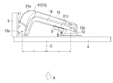
- the attachment portion 31d is arranged on the door 4 side of the main arm 13.
- the connecting bar 3 is attached to the door 4 side of the main arm 13. Further, in a front view (shown by a white arrow A in FIG. 9) in a state where the door 4 is in the closed position, the center B ′ in the width direction of the mounting portion 31 d and the center B in the width direction of the connecting bar 3 are mainly It is arranged closer to the second shaft 13b than the center C between the first shaft 13a of the arm 13 and the second shaft 13b of the main arm 13. In this embodiment, the entire mounting portion 31d and the entire connecting bar 3 are disposed closer to the second shaft 13b side than the center C. As shown in FIG. 8, the connecting bar 3 is located forward of the first link 14 and the second link 15 in the opening direction from the closed position to the opened position of the door 4, and the connecting bar 3 is the first link. 14 and the second link 15 are not interfered with.
- the configuration of the door opening / closing device 1 of this embodiment has been described above.
- the door opening / closing device 1 of the present embodiment has the following effects.
- the main arm 13 has a bent portion 31a, and the main arm 13 approaches the door 4 as it approaches the second shaft 13b. Since the connecting bar 3 is arranged on the door 4 side of the main arm 13 and on the second shaft 13b side, the connecting bar 3 can be brought close to the back surface of the door 4. Therefore, the storage space of the main body 5 can be widened.
- the connecting bar 3 is arranged close to the second shaft 13b, it is possible to prevent the shelf 5b from interfering with the connecting bar 3 even if the shelf 5b is attached to the side plate 5a of the main body 5 as shown in FIG. It can be prevented.
- the strength of the door opening / closing device 1 can be ensured and the door opening / closing can be performed.
- the device 1 can be made compact.
- the main arm 13 has a metal arm body 31 having a U-shaped cross section and a metal assist arm 32 having a U-shaped cross section that is fastened to the arm body 31, and is formed in a tubular shape having a quadrangular cross section. Therefore, the strength of the main arm 13 can be secured.
- the main arm 13 is provided with the finger pinch prevention cover 41 that reduces or eliminates the gap (the gap in the axial direction and the axial gaps ⁇ 1 and ⁇ 2) between the main arm 13 and the first link 14, so that these gaps are provided. It can prevent fingers from being caught. The same applies to the gap between the main arm 13 and the second link 15.
- the door opening / closing device is attached to the side plate of the main body to open / close the door left / right, but the door opening / closing device may be attached to the upper plate or the lower plate of the main body to open / close the door vertically.
- the connecting bars are attached to the pair of hinges, but the connecting bars can be attached to three or more hinges.
Abstract
L'invention concerne un dispositif d'ouverture/fermeture de porte avec lequel un espace de logement d'un corps peut être augmenté. Le dispositif d'ouverture/fermeture de porte (1) comprend au moins deux charnières (2a, 2b), et une barre de liaison (3) qui est reliée aux au moins deux charnières (2a, 2b). Chaque charnière (2a, 2b) comprend un élément côté corps (11), un élément côté porte (12), un bras principal (13), une première liaison (14), et une seconde liaison (15), et amène la porte (4) à se déplacer de manière parallèle entre une position fermée et une position ouverte. Le bras principal (13) possède une section pliée (31a). La barre de liaison (3) est fixée au côté porte (4) du bras principal (13). Dans une vue avant (A) de la porte (4), dans laquelle celle-ci (4) est dans la position fermée, le centre (B) de la barre de liaison (3) dans le sens de la largeur de celle-ci est disposé plus vers un côté d'un second arbre (13b) que le centre (C) entre un premier arbre (13a) et le second arbre (13b) du bras principal (13).
Priority Applications (4)
| Application Number | Priority Date | Filing Date | Title |
|---|---|---|---|
| US17/288,337 US11384581B2 (en) | 2018-10-23 | 2019-10-04 | Door opening/closing apparatus and hinge |
| CN201980065801.7A CN112840095B (zh) | 2018-10-23 | 2019-10-04 | 门扇开闭装置和合页 |
| EP19876245.2A EP3872287A4 (fr) | 2018-10-23 | 2019-10-04 | Dispositif d'ouverture/fermeture de porte et charnière |
| JP2020507128A JP6851704B2 (ja) | 2018-10-23 | 2019-10-04 | 扉開閉装置及びヒンジ |
Applications Claiming Priority (2)
| Application Number | Priority Date | Filing Date | Title |
|---|---|---|---|
| JP2018198999 | 2018-10-23 | ||
| JP2018-198999 | 2018-10-23 |
Publications (1)
| Publication Number | Publication Date |
|---|---|
| WO2020085043A1 true WO2020085043A1 (fr) | 2020-04-30 |
Family
ID=70330966
Family Applications (1)
| Application Number | Title | Priority Date | Filing Date |
|---|---|---|---|
| PCT/JP2019/039266 WO2020085043A1 (fr) | 2018-10-23 | 2019-10-04 | Dispositif d'ouverture/fermeture de porte et charnière |
Country Status (5)
| Country | Link |
|---|---|
| US (1) | US11384581B2 (fr) |
| EP (1) | EP3872287A4 (fr) |
| JP (1) | JP6851704B2 (fr) |
| CN (1) | CN112840095B (fr) |
| WO (1) | WO2020085043A1 (fr) |
Families Citing this family (1)
| Publication number | Priority date | Publication date | Assignee | Title |
|---|---|---|---|---|
| US11866978B2 (en) * | 2020-12-01 | 2024-01-09 | Questar Gas Company | Door swing control device and associated method |
Citations (5)
| Publication number | Priority date | Publication date | Assignee | Title |
|---|---|---|---|---|
| JPS6019258Y2 (ja) * | 1979-10-09 | 1985-06-10 | 政雄 村越 | ヒンジ用カバ− |
| JP2010242427A (ja) * | 2009-04-08 | 2010-10-28 | Sugatsune Ind Co Ltd | ヒンジ装置及びヒンジ装置用取付部材 |
| JP2011212090A (ja) * | 2010-03-31 | 2011-10-27 | Daiken Corp | 仏壇 |
| JP5291810B2 (ja) | 2012-01-06 | 2013-09-18 | スガツネ工業株式会社 | スライドヒンジ及び収容装置 |
| JP2018198999A (ja) | 2018-09-26 | 2018-12-20 | 株式会社ユニバーサルエンターテインメント | 遊技機 |
Family Cites Families (20)
| Publication number | Priority date | Publication date | Assignee | Title |
|---|---|---|---|---|
| DE2950857C2 (de) | 1979-12-18 | 1985-02-14 | Team Form Ag, Hinwil | Türbeschlag zur Parallelführung einer Tür |
| JPS6019258A (ja) | 1983-07-13 | 1985-01-31 | Nec Corp | 記憶装置 |
| JPH0411857Y2 (fr) * | 1984-11-02 | 1992-03-24 | ||
| DE19754417C2 (de) * | 1997-12-09 | 2001-07-26 | Lunke Ventra Automotive Gmbh | Tür-Scharnier |
| US6647592B2 (en) * | 2000-12-19 | 2003-11-18 | Daimlerchrysler Corporation | Four bar hinge |
| US6629337B2 (en) * | 2001-11-28 | 2003-10-07 | Edscha Roof Systems Inc. | Double-pivot resistance hinge for motor vehicle door |
| ITMI20021434A1 (it) * | 2002-06-28 | 2003-12-29 | Antonio Giovannetti | Meccanismo per ante a parallelogramma articolato per apertura/chiusura delle stesse |
| JP2004360180A (ja) | 2003-05-30 | 2004-12-24 | Shimodaira:Kk | 家具扉の開閉装置 |
| US6889404B2 (en) * | 2003-07-18 | 2005-05-10 | Shin Zu Shing Co., Ltd. | Height-adjustable hinge for a liquid crystal display |
| US7971320B2 (en) * | 2008-01-11 | 2011-07-05 | GM Global Technology Operations LLC | Door hinge assembly |
| EP2325425B1 (fr) | 2008-08-12 | 2019-02-27 | Sugatsune Kogyo CO., LTD. | Dispositif d'articulation et dispositif de logement |
| US8007026B2 (en) * | 2009-06-02 | 2011-08-30 | Ford Global Technologies, Llc | Lockout feature for full open hinge |
| JP5177569B2 (ja) * | 2009-08-27 | 2013-04-03 | キャタピラー エス エー アール エル | ヒンジおよびドア装置 |
| EP2363560B1 (fr) | 2010-03-05 | 2013-01-02 | Parosha Holding B.V. | Ensemble de porte |
| KR20120122428A (ko) * | 2011-04-29 | 2012-11-07 | 탁동호 | 180도 개문이 가능한 가구용 엑스바형 도어 힌지 |
| US9332842B2 (en) * | 2012-03-28 | 2016-05-10 | BIOMéRIEUX, INC. | Sliding hinges and related methods and devices suitable for apparatus for automated evaluation of microorganism growth in test samples |
| US9217269B2 (en) | 2014-05-02 | 2015-12-22 | GM Global Technology Operations LLC | Hinge assembly |
| CN107429531B (zh) | 2015-03-16 | 2019-10-01 | 世嘉智尼工业株式会社 | 合叶装置 |
| JP6453280B2 (ja) | 2016-08-30 | 2019-01-16 | 有限会社新井鉄工 | 扉体開閉装置 |
| US10968671B2 (en) * | 2017-06-02 | 2021-04-06 | Nissan North America, Inc. | Adjustable vehicle hinge assembly |
-
2019
- 2019-10-04 JP JP2020507128A patent/JP6851704B2/ja active Active
- 2019-10-04 CN CN201980065801.7A patent/CN112840095B/zh active Active
- 2019-10-04 EP EP19876245.2A patent/EP3872287A4/fr active Pending
- 2019-10-04 US US17/288,337 patent/US11384581B2/en active Active
- 2019-10-04 WO PCT/JP2019/039266 patent/WO2020085043A1/fr unknown
Patent Citations (5)
| Publication number | Priority date | Publication date | Assignee | Title |
|---|---|---|---|---|
| JPS6019258Y2 (ja) * | 1979-10-09 | 1985-06-10 | 政雄 村越 | ヒンジ用カバ− |
| JP2010242427A (ja) * | 2009-04-08 | 2010-10-28 | Sugatsune Ind Co Ltd | ヒンジ装置及びヒンジ装置用取付部材 |
| JP2011212090A (ja) * | 2010-03-31 | 2011-10-27 | Daiken Corp | 仏壇 |
| JP5291810B2 (ja) | 2012-01-06 | 2013-09-18 | スガツネ工業株式会社 | スライドヒンジ及び収容装置 |
| JP2018198999A (ja) | 2018-09-26 | 2018-12-20 | 株式会社ユニバーサルエンターテインメント | 遊技機 |
Non-Patent Citations (1)
| Title |
|---|
| See also references of EP3872287A4 |
Also Published As
| Publication number | Publication date |
|---|---|
| EP3872287A1 (fr) | 2021-09-01 |
| CN112840095B (zh) | 2022-09-09 |
| JP6851704B2 (ja) | 2021-03-31 |
| JPWO2020085043A1 (ja) | 2021-02-15 |
| CN112840095A (zh) | 2021-05-25 |
| EP3872287A4 (fr) | 2022-08-03 |
| US11384581B2 (en) | 2022-07-12 |
| US20210381291A1 (en) | 2021-12-09 |
Similar Documents
| Publication | Publication Date | Title |
|---|---|---|
| EP1555372B1 (fr) | Dispositif de charnière | |
| US8904600B2 (en) | Hinge apparatus and container apparatus | |
| US8250706B2 (en) | Hinge for doors | |
| JP4723013B2 (ja) | 位置調節機能付きカップ埋め込み式ヒンジ装置 | |
| US20120117757A1 (en) | Biaxial hinge device | |
| US10724284B2 (en) | Appliance lid hinge assembly with snubber | |
| JP5004058B2 (ja) | チェックリンク装置 | |
| WO2018216564A1 (fr) | Dispositif pour portes | |
| WO2020085043A1 (fr) | Dispositif d'ouverture/fermeture de porte et charnière | |
| WO2021039254A1 (fr) | Charnière à axe unique | |
| JP2020523508A (ja) | 閉鎖力を調節するための装置を有する家具用ヒンジ | |
| JP2016125337A (ja) | 車両用ドアのドアチェック機構 | |
| US7770191B2 (en) | Tray door attachment structure for disk device | |
| JP2005240465A (ja) | 扉体開閉装置 | |
| JP5697409B2 (ja) | 建具用ランナー | |
| JP2020190259A (ja) | ヒンジ装置 | |
| KR100705131B1 (ko) | 도어힌지구조 | |
| KR100896908B1 (ko) | 차량용 트렁크의 토션바 조립구조 | |
| JP4589551B2 (ja) | 遊戯機扉のヒンジ機構 | |
| KR102032239B1 (ko) | 자동차의 암레스트 힌지 | |
| JP6990783B2 (ja) | 引戸装置 | |
| KR100420363B1 (ko) | 전자레인지의 도어 개폐장치 | |
| US7437802B2 (en) | Door hinge with checker | |
| JP2008241840A (ja) | ピアノの奥屋根固定装置 | |
| JP2023148928A (ja) | ヒンジ及びヒンジを備えた電子機器 |
Legal Events
| Date | Code | Title | Description |
|---|---|---|---|
| ENP | Entry into the national phase |
Ref document number: 2020507128 Country of ref document: JP Kind code of ref document: A |
|
| 121 | Ep: the epo has been informed by wipo that ep was designated in this application |
Ref document number: 19876245 Country of ref document: EP Kind code of ref document: A1 |
|
| NENP | Non-entry into the national phase |
Ref country code: DE |
|
| ENP | Entry into the national phase |
Ref document number: 2019876245 Country of ref document: EP Effective date: 20210525 |