WO2020080419A1 - 鉛蓄電池 - Google Patents
鉛蓄電池 Download PDFInfo
- Publication number
- WO2020080419A1 WO2020080419A1 PCT/JP2019/040715 JP2019040715W WO2020080419A1 WO 2020080419 A1 WO2020080419 A1 WO 2020080419A1 JP 2019040715 W JP2019040715 W JP 2019040715W WO 2020080419 A1 WO2020080419 A1 WO 2020080419A1
- Authority
- WO
- WIPO (PCT)
- Prior art keywords
- positive electrode
- electrode material
- mass
- less
- current collector
- Prior art date
- Legal status (The legal status is an assumption and is not a legal conclusion. Google has not performed a legal analysis and makes no representation as to the accuracy of the status listed.)
- Ceased
Links
Images



Classifications
-
- H—ELECTRICITY
- H01—ELECTRIC ELEMENTS
- H01M—PROCESSES OR MEANS, e.g. BATTERIES, FOR THE DIRECT CONVERSION OF CHEMICAL ENERGY INTO ELECTRICAL ENERGY
- H01M10/00—Secondary cells; Manufacture thereof
- H01M10/06—Lead-acid accumulators
-
- H—ELECTRICITY
- H01—ELECTRIC ELEMENTS
- H01M—PROCESSES OR MEANS, e.g. BATTERIES, FOR THE DIRECT CONVERSION OF CHEMICAL ENERGY INTO ELECTRICAL ENERGY
- H01M4/00—Electrodes
- H01M4/02—Electrodes composed of, or comprising, active material
- H01M4/14—Electrodes for lead-acid accumulators
-
- H—ELECTRICITY
- H01—ELECTRIC ELEMENTS
- H01M—PROCESSES OR MEANS, e.g. BATTERIES, FOR THE DIRECT CONVERSION OF CHEMICAL ENERGY INTO ELECTRICAL ENERGY
- H01M4/00—Electrodes
- H01M4/02—Electrodes composed of, or comprising, active material
- H01M4/36—Selection of substances as active materials, active masses, active liquids
- H01M4/48—Selection of substances as active materials, active masses, active liquids of inorganic oxides or hydroxides
- H01M4/56—Selection of substances as active materials, active masses, active liquids of inorganic oxides or hydroxides of lead
-
- H—ELECTRICITY
- H01—ELECTRIC ELEMENTS
- H01M—PROCESSES OR MEANS, e.g. BATTERIES, FOR THE DIRECT CONVERSION OF CHEMICAL ENERGY INTO ELECTRICAL ENERGY
- H01M4/00—Electrodes
- H01M4/02—Electrodes composed of, or comprising, active material
- H01M4/64—Carriers or collectors
- H01M4/66—Selection of materials
- H01M4/68—Selection of materials for use in lead-acid accumulators
-
- H—ELECTRICITY
- H01—ELECTRIC ELEMENTS
- H01M—PROCESSES OR MEANS, e.g. BATTERIES, FOR THE DIRECT CONVERSION OF CHEMICAL ENERGY INTO ELECTRICAL ENERGY
- H01M4/00—Electrodes
- H01M4/02—Electrodes composed of, or comprising, active material
- H01M4/64—Carriers or collectors
- H01M4/66—Selection of materials
- H01M4/68—Selection of materials for use in lead-acid accumulators
- H01M4/685—Lead alloys
-
- H—ELECTRICITY
- H01—ELECTRIC ELEMENTS
- H01M—PROCESSES OR MEANS, e.g. BATTERIES, FOR THE DIRECT CONVERSION OF CHEMICAL ENERGY INTO ELECTRICAL ENERGY
- H01M4/00—Electrodes
- H01M4/02—Electrodes composed of, or comprising, active material
- H01M4/64—Carriers or collectors
- H01M4/70—Carriers or collectors characterised by shape or form
- H01M4/72—Grids
- H01M4/73—Grids for lead-acid accumulators, e.g. frame plates
-
- H—ELECTRICITY
- H01—ELECTRIC ELEMENTS
- H01M—PROCESSES OR MEANS, e.g. BATTERIES, FOR THE DIRECT CONVERSION OF CHEMICAL ENERGY INTO ELECTRICAL ENERGY
- H01M4/00—Electrodes
- H01M4/02—Electrodes composed of, or comprising, active material
- H01M4/64—Carriers or collectors
- H01M4/82—Multi-step processes for manufacturing carriers for lead-acid accumulators
-
- H—ELECTRICITY
- H01—ELECTRIC ELEMENTS
- H01M—PROCESSES OR MEANS, e.g. BATTERIES, FOR THE DIRECT CONVERSION OF CHEMICAL ENERGY INTO ELECTRICAL ENERGY
- H01M4/00—Electrodes
- H01M4/02—Electrodes composed of, or comprising, active material
- H01M2004/021—Physical characteristics, e.g. porosity, surface area
-
- H—ELECTRICITY
- H01—ELECTRIC ELEMENTS
- H01M—PROCESSES OR MEANS, e.g. BATTERIES, FOR THE DIRECT CONVERSION OF CHEMICAL ENERGY INTO ELECTRICAL ENERGY
- H01M4/00—Electrodes
- H01M4/02—Electrodes composed of, or comprising, active material
- H01M2004/026—Electrodes composed of, or comprising, active material characterised by the polarity
- H01M2004/028—Positive electrodes
-
- Y—GENERAL TAGGING OF NEW TECHNOLOGICAL DEVELOPMENTS; GENERAL TAGGING OF CROSS-SECTIONAL TECHNOLOGIES SPANNING OVER SEVERAL SECTIONS OF THE IPC; TECHNICAL SUBJECTS COVERED BY FORMER USPC CROSS-REFERENCE ART COLLECTIONS [XRACs] AND DIGESTS
- Y02—TECHNOLOGIES OR APPLICATIONS FOR MITIGATION OR ADAPTATION AGAINST CLIMATE CHANGE
- Y02E—REDUCTION OF GREENHOUSE GAS [GHG] EMISSIONS, RELATED TO ENERGY GENERATION, TRANSMISSION OR DISTRIBUTION
- Y02E60/00—Enabling technologies; Technologies with a potential or indirect contribution to GHG emissions mitigation
- Y02E60/10—Energy storage using batteries
Definitions
- the present invention relates to a lead storage battery.
- a lead-acid battery comprises a group of electrode plates in which positive electrode plates and negative electrode plates are alternately laminated with separators in between.
- the electrode plate is composed of a current collector and an electrode material held by the current collector.
- a punching grid formed by press punching as a current collector has less restriction on the grid design than the expanded grid, and has an advantage that a grid design having excellent conductivity can be selected.
- Patent Document 1 discloses a lead grid plate obtained by press-punching a rolled plate of a lead alloy, in which the thickness of the internal vertical and horizontal bars is smaller than the thickness of the outer frame and the outer frame has a thickness of 0. It is proposed that the thickness of the crosspiece is 8 to 1.5 mm and the thickness of the crosspiece is 0.6 to 0.8 mm. In addition, the thickness of the internal vertical and horizontal bars is obtained by deforming the inner frame of the lead grid plate made by press-punching a 1.2 to 1.5 mm thick lead alloy rolled plate in the thickness direction. Is proposed to be set within the range of 0.6 to 0.8 mm.
- Patent Document 2 discloses a ratio (Vp +) of the total volume Vp + Vn of the total pore volume Vp of the positive electrode active material and the total pore volume Vn of the negative electrode active material to the volume Ve of the electrode plate group in the liquid lead acid battery.
- Vn) / Ve is 0.27 to 0.32
- the ratio Vp / Ve of the total pore volume Vp of the positive electrode active material to the volume Ve of the electrode plate group is 0.13 to 0.15. is suggesting. Further, it is described that the antimony content of the positive electrode active material is 0.04 to 0.25% by mass.
- Patent Document 3 discloses a lead-acid battery in which the electrolytic solution contains sulfuric acid and Al ions, and the already formed positive electrode active material contains Sn, and the Sn concentration in the already formed positive electrode active material is 0.05 to 1. 0 mass%, the Al ion concentration in the electrolytic solution was 0.02 to 0.2 mol / L, and the Sb concentration in the surface layer of a part of the positive electrode grid made of the Pb—Ca alloy was 1. It is described that a Pb—Sb alloy layer of 0 to 10 mass% is provided.
- life performance may decrease due to deterioration of the positive electrode.
- the deterioration mode of the positive electrode for example, sulfation, dropping or softening of the positive electrode material, corrosion of the current collector, and the like can be considered.
- the state of the current collector varies greatly depending on the processing method and processing conditions.
- the adhesion to the positive electrode material and the corrosion resistance are also different. Therefore, sufficient life performance may not be obtained depending on the state of the current collector. Further, the life performance greatly varies depending on the charging / discharging conditions.
- One aspect of the present invention is a lead storage battery, which includes a positive electrode plate, a negative electrode plate, and an electrolytic solution
- the positive electrode plate includes a current collector, and a positive electrode material held by the current collector
- the current collector has a frame bone, an ear provided on the frame bone, and an internal bone inside the frame bone
- the frame bone includes an upper element continuous with the ear, a lower element facing the upper element, and a pair of side elements connecting the upper element and the lower element
- the internal bone includes a longitudinal bone extending in a first direction from the upper element toward the lower element, and a horizontal bone extending in a second direction from the one side element toward the other side element.
- the outer peripheral region of the cross section is composed of a first portion in which the fibrous tissue extends along the contour of the cross section, and a second portion other than the first portion,
- the ratio R2 of the length of the contour corresponding to the second portion to the total length of the contour of the cross section is less than 50%
- the positive electrode material contains at least one selected from the group consisting of Sn and Sb,
- the content c1 of Sn in the positive electrode material is less than 0.75 mass%
- the content c2 of Sb in the positive electrode material is less than 0.50 mass%
- the sum c3 of c1 and c2 relates to the lead storage battery, which is less than 0.8% by mass.
- the lead-acid battery includes a positive electrode plate, a negative electrode plate, and an electrolytic solution.
- the positive electrode plate includes a current collector and a positive electrode material held by the current collector.
- the current collector has a frame bone, an ear provided on the frame bone, and an internal bone inside the frame bone.
- the frame bone comprises an upper element continuous with the ear, a lower element facing the upper element, and a pair of side elements connecting the upper element and the lower element.
- the internal bone comprises a longitudinal bone extending in a first direction from the upper element toward the lower element, and a lateral bone extending in a second direction from one side element toward the other side element.
- the first direction is a direction parallel to the side element
- the second direction is a direction parallel to the upper element and the lower element.
- the longitudinal bone may extend parallel to the side element or may extend obliquely to the side element.
- the vertical bone may have a linear shape, a curved shape, or may have some bending. That is, the vertical bones may extend so that the vector in the first direction is larger than the vector in the second direction.
- the transverse bone may extend parallel to the upper element or the lower element, or may extend obliquely to the upper element or the lower element. Further, the horizontal bone may have a linear shape, a curved shape, or a slight bend. That is, the transverse bone may extend so that the vector in the second direction is larger than the vector in the first direction.
- a striped pattern of metallic fibrous tissue is seen in a cross section perpendicular to the first direction of the longitudinal bone, that is, a cross section parallel to the upper element and parallel to the thickness direction (hereinafter, also referred to as cross section C).
- the outer peripheral region of the cross section C is composed of a first portion in which the fibrous tissue (direction of stripes) extends along the contour of the cross section C, and a second portion other than the first portion.
- the contour of the cross section C means a line corresponding to the outer surface of the longitudinal bone.
- the outer peripheral region of the cross section C is a peripheral region along the contour of the cross section C, and has a depth of at least 55 ⁇ m or more, preferably 100 ⁇ m or more from the line corresponding to the outer surface in the cross section C. Area. In the second portion of the cross section C, the striped pattern may not be observed, and the striped pattern extending in the depth direction of the outer peripheral region may be observed.
- the ratio R2 of the length of the contour corresponding to the second portion to the total length of the contour of the cross section C is less than 50%.
- the ratio R2 when controlled, it becomes difficult to expose the cross section perpendicular to the fiber length of the fibrous tissue on the outer surface of the outer peripheral region of the cross section C.
- the cross section of the fibrous tissue perpendicular to the fiber length has many grain boundaries.
- the first part and the second part differ in the mode of progress of corrosion.
- the positive electrode material contains at least one selected from the group consisting of Sn and Sb.
- the content c1 of Sn in the positive electrode material is less than 0.75 mass%
- the content c2 of Sb in the positive electrode material is less than 0.50 mass%
- the sum c3 of c1 and c2 is It is less than 0.8 mass%.
- the ratio R2 of the length of the contour corresponding to the second portion to the entire length of the contour of the cross section C of the longitudinal bone is set to less than 50%, and Sn in the positive electrode material is The content c1, the content c2 of Sb, and the total c3 thereof are controlled within the above range.
- the second portion of the first cross section (cross section C) of the longitudinal bone has a cross section perpendicular to the striped pattern of fibrous tissue.
- the proportion R2 of the second portion being less than 50% means that the proportion of the length of the contour corresponding to the first portion to the total length of the contour of the cross section C is greater than 50%.
- the cross section perpendicular to the second direction of the transverse bone that is, the cross section parallel to the side elements and parallel to the thickness direction (hereinafter, also referred to as cross section G)
- the striped pattern of the metal fibrous tissue is almost observed.
- a cross section perpendicular to the fiber length of the fibrous tissue is generally seen.
- the outer peripheral area of the cross section G generally the entire circumference corresponds to the second portion of the cross section C. That is, the outer peripheral region of the cross section G is composed of a fibrous tissue that extends in the second direction substantially all around.
- corrosion of the current collector preferentially progresses in a cross section perpendicular to the fiber length of the fibrous tissue exposed on the outer surface.
- the fibrous metal tissue extends in the plane direction of the inner bone. That is, the crystal grain boundaries extend longer in the plane direction of the internal bone than in the depth direction of the internal bone. Therefore, the corrosion layer formed in the first portion of the outer peripheral region is formed along the surface direction of the internal bone and is unlikely to be formed deep inside the internal bone.
- the corrosion layer formed along the outer surface of the first portion of the outer peripheral region has low bonding strength with the current collector (inner bone).
- the corrosion layer when gas is generated at the interface between the current collector (the outer surface of the first portion of the outer peripheral region) and the corrosion layer, the corrosion layer is relatively easily separated from the current collector.
- the fibrous metal tissue extends in the depth direction of the inner bone. That is, the crystal grain boundaries extend longer in the depth direction of the internal bone than in the plane direction of the internal bone. Therefore, the corrosion layer formed along the outer surface of the second portion of the outer peripheral region has high bonding strength with the current collector (inner bone). Even if gas is generated at the interface between the current collector (second portion of the outer peripheral region) and the corrosion layer, the corrosion layer is difficult to separate from the current collector, and stresses the internal bone to deform the internal bone.
- the corrosion layer is less likely to peel off than in the first portion where the fibrous metal tissue extends in the plane direction of the inner bone.
- Is susceptible to stress from the corrosion layer which causes deformation of the current collector.
- the lead storage battery is used under the condition that the charge amount is larger than the discharge amount, the influence of the stress that the second portion receives from the corrosion layer is likely to become apparent. Therefore, even if the amount of corrosion is the same, the elongation and distortion of the current collector are suppressed as the first partial ratio increases.
- the ratio R2 of the second portion is less than 50%, the formation of a deep corrosion layer can be suppressed, so that the elongation and strain of the current collector can be suppressed.
- the proportion of the first portion where the shallow corrosion layer is formed is relatively large, the adhesiveness between the current collector and the positive electrode material (initial adhesiveness) is likely to decrease.
- the volume change due to the expansion and contraction of the positive electrode active material further lowers the adhesion between the current collector and the positive electrode material.
- deep discharge and charging are repeated, so that the volume change of the positive electrode active material becomes large and the adhesiveness is apt to be significantly reduced.
- Insulating lead sulfate easily accumulates in the gap formed in the positive electrode plate due to the decrease in adhesion, and this lead sulfate acts as a resistance, causing the PCL (Premature Capacity Loss) phenomenon to reach the end of life with a small number of cycles. May cause. Further, when the positive electrode material is peeled off due to the decrease in adhesion, the reaction is concentrated on the positive electrode material which has not been peeled off, and softening occurs, which may reach the end of life.
- PCL Premature Capacity Loss
- the ratio R2 of the second portion is set to less than 50%, whereby the elongation and strain of the current collector are suppressed from increasing even in a heavy load cycle.
- the positive electrode material contains Sn and / or Sb, a conductive path can be secured between the positive electrode material and the current collector.
- the ratio R2 is less than 50%, it becomes difficult to secure the adhesion between the positive electrode material and the current collector, but the above-mentioned conductive path promotes conversion of lead sulfate to lead dioxide. Therefore, the accumulation of lead sulfate in the gap in the positive electrode plate is suppressed. Therefore, the occurrence of the PCL phenomenon can be suppressed even when the heavy load cycle is repeated. By suppressing the decrease in conductivity of the positive electrode plate, softening of the positive electrode material can be suppressed even when the heavy load cycle is repeated. Therefore, it is possible to secure high life performance in a heavy load cycle.
- the amount of charge with respect to the amount of discharge is large, and gas generation is likely to occur, but by setting the content of Sn and / or Sb within the above range, gas generation is suppressed and the liquid reduction amount is increased. Can be suppressed. Therefore, it can be said that the life characteristics in the heavy load cycle can be improved also from such a viewpoint, because the life is suppressed by the liquid reduction.
- the ratio R2 of the second portion can be intentionally controlled.
- the ratio R2 can be arbitrarily controlled by the speed of the press, the press pressure, the die shape, and the like.
- the deformation of the longitudinal bone by press working is not a sufficient condition for reducing the ratio R2, but it is necessary to appropriately control the condition of press working.
- the ratio R2 is small, the elongation and strain of the current collector can be suppressed, and the positive electrode material can be suppressed from being physically separated from the current collector.
- the ratio R2 of the second portion is less than 50%, preferably 40% or less, and may be 30% or less.
- the ratio R2 is preferably 20% or more, more preferably 30% or more.
- These upper limit values and lower limit values can be arbitrarily combined.
- the content c1 of Sn is preferably 0.01% by mass or more and 0.5% by mass or less
- the content c2 of Sb is 0.01% by mass or more and 0.3% by mass or less.
- the total c3 of c1 and c2 is preferably 0.01% by mass or more, and more preferably 0.7% by mass or less.
- the ratio R2 and the contents c1, c2 and / or c3 are in such ranges, the effect of suppressing the occurrence of the PCL phenomenon and the liquid reduction is enhanced in the heavy load cycle, and the softening of the positive electrode material is further suppressed. be able to. Therefore, higher life performance can be secured in the heavy load cycle.
- the Sn content c1 is the Sn element-equivalent Sn content in the positive electrode material after chemical conversion.
- the Sb content c2 is the Sb content in terms of Sb element in the positive electrode material after chemical conversion.
- the life performance in a heavy load cycle means discharge in a region where the depth of one discharge is 20% or more (also referred to as a heavy load region) when the rated capacity (5 hour rate capacity) is 100%. It means the life performance when the cycle of charging and charging is repeated.
- the positive electrode material preferably contains at least Sn.
- the density of the positive electrode material is preferably 3.4 g / cm 3 or more and 4.8 g / cm 3 or less (preferably 4.6 g / cm 3 or less).
- the density is in such a range, elongation and distortion of the current collector are easily suppressed by the action of the ratio R2, the durability of the electrode material is easily secured to some extent, and conductivity is improved by Sn and / or Sb. The effect is easily exhibited. Therefore, when the density is such a density, it is advantageous in ensuring higher life performance.
- the density of the positive electrode material means the value of the bulk density of the positive electrode material in a fully charged state, and is measured as follows. After the chemical conversion or during use (preferably at the beginning of use), the battery is fully charged, disassembled, and the obtained positive electrode plate is washed with water and dried to remove the electrolytic solution in the positive electrode plate. (The washing with water is carried out by pressing a pH test paper against the surface of the washed electrode plate until it is confirmed that the color of the test paper does not change. However, the time for washing with water is within 2 hours. Is dried for about 6 hours at 60 ° C. ⁇ 5 ° C.
- the positive electrode material is separated from the positive plate to obtain an unground measurement sample.
- the mercury was filled at a pressure of 0.5 psia or more and 0.55 psia or less ( ⁇ 3.45 kPa or more and 3.79 kPa or less) to measure the bulk volume of the positive electrode material,
- the bulk density of the positive electrode material is obtained by dividing the mass of the measurement sample by the bulk volume.
- the volume obtained by subtracting the volume of mercury injected from the volume of the measurement container is the bulk volume.
- the density of the positive electrode material is measured using an automatic porosimeter (Autopore IV9505) manufactured by Shimadzu Corporation.
- a fully charged state of a lead storage battery means, in the case of a liquid type battery, a current (A) 0.2 times the value described as the rated capacity (Ah) in a water tank of 25 ° C ⁇ 2 ° C. After constant-current charging until reaching 2.5 V / cell, the constant-current charging was further performed for 2 hours at a current (A) 0.2 times the value described as the rated capacity (Ah). .
- the fully charged state means that the current (A) is 0.2 times the value described as the rated capacity (Ah) in the air chamber at 25 ° C ⁇ 2 ° C.
- the lead storage battery may be fully charged after the formation, for example, immediately after the formation or after a lapse of time from the formation (for example, after the formation, during use (preferably used). (Initial) may be fully charged lead acid battery).
- the shape of the cross section C of the vertical bone is not particularly limited, but is preferably an octagon. If the cross-section C is octagonal, the interior angle of the apex does not become too small, and the effect of suppressing corrosion near the apex can be easily enhanced.
- a vertical bone having an octagonal cross section C for example, a vertical bone having a rectangular cross section C may be deformed.
- the method of deforming the longitudinal bone is not particularly limited, but for example, the inner bone of the current collector may be pressed. At that time, the press condition of the internal bone may be appropriately selected so that the ratio R2 of the second portion falls within a predetermined range.
- the octagon does not have to be a strict octagon in the mathematical sense, and the vertices may be slightly rounded or each side may be slightly curved.
- the above aspect of the present invention is useful when a punched current collector is used as the current collector of the positive electrode, as described above.
- a punched current collector made of a drawn sheet of lead or lead alloy is preferable. Since the stretched sheet easily produces a striped pattern of a metallic fibrous structure, it becomes easy to adjust the proportion of the second portion.
- the fibrous tissue extends along the contour of the outer peripheral region of the cross section C in the first portion means the following state.
- the inside of the skeleton of the current collector is divided into an upper region on the upper element side of the skeleton, a lower region on the lower element side of the skeleton, and a middle region between the upper region and the lower region. Cut as described.
- four rows of the cross section C perpendicular to the first direction are formed in the plurality of vertical bones. That is, one row having a cross section C is formed in each of the upper region and the lower region, and two rows having a cross section C are formed in the middle region.
- the division line is entirely formed so that the cross section C is formed in the vertical bone portion between the intersections as much as possible.
- the current collector may be partially moved to divide it into three. When dividing the inside of the frame bone of the current collector into three, the dimensions of the ears or feet are not taken into consideration.
- a plurality of cross sections C to be observed (60% or more of the cross sections C included in the two rows) are selected from any two rows out of the four rows.
- the portion where the fringes of the fibrous tissue form an angle of less than 45 ° with the contour of the cross section C with reference to the horizontal plane in the first direction from the side element is the first portion.
- the parts other than the first part are the second part. Specifically, at an arbitrary point P on the contour of each cross section C, a tangent line S1 of the point P is drawn, and a perpendicular line L of the tangent line S1 is drawn so as to pass through the point P.
- a tangent line S2 of a stripe existing at a depth of 55 ⁇ m from the point P on the perpendicular L and intersecting the perpendicular L is drawn at the intersection. If the angle ⁇ between the tangent line S2 and the tangent line S1 is less than 45 °, the point P constitutes the contour corresponding to the first portion. When the angle ⁇ is 45 ° or more, the point P constitutes the contour corresponding to the second portion. Even when it is not possible to determine whether or not the point P constitutes the contour corresponding to the first portion because the fibrous tissue cannot be observed, the point P constitutes the contour of the second portion.
- the ratio of the length of the contour corresponding to the second portion to the total length of the contour of the cross-section C is calculated and averaged to calculate the ratio R2.
- the average may be obtained excluding the cross section, and the cutting position of the vertical bone may be shifted so that the node deviates.
- the prepared current collector is embedded in a thermosetting resin to cure the resin and then the current collector is cut.
- a current collector before being filled with the positive electrode material may be used, or a current collector obtained by disassembling and taking out a lead storage battery in a fully charged state may be used. In the latter case, first, the battery is disassembled and the electrode plate taken out is washed with water to remove the electrolytic solution containing sulfuric acid and dried. Then, the positive electrode material is removed from the positive electrode plate, and the positive electrode material attached to the surface of the current collector is removed by mannite. The state of the metal structure of the cross section C is photographed and observed with a microscope after etching the cross section of the current collector.
- the mass of the positive electrode material is the mass when the positive electrode material taken out from the lead storage battery in a fully charged state is washed and dried, and the Sn content c1 and the Sb content c2 are respectively It refers to the mass ratio of Sn and the mass ratio of Sb in the positive electrode material. It is possible that Sn or Sb exists in the form of a compound (for example, an oxide or a sulfuric acid compound), but even in that case, the Sn content and Sb should be taken into consideration in consideration of only the mass of Sn or Sb in the compound. The content should be calculated.
- the Sn content and Sb content in the positive and negative electrode materials were determined by disassembling the lead storage battery in a fully charged state, washing the electrode plate taken out with water, drying and collecting the electrode material, and dissolving the crushed sample in concentrated nitric acid. It is obtained by performing ICP (Inductively Coupled Plasma) emission analysis.
- ICP Inductively Coupled Plasma
- the thickness of the first portion (in other words, the thickness of the fibrous tissue) may be 55 ⁇ m or more. Further, even if the outer peripheral region looks like the first part at first glance, if the thickness of the region where the striped pattern of the fibrous tissue is observed is less than 55 ⁇ m, it is regarded as the second part, not the first part.
- the first portion having a thickness of 55 ⁇ m or more has a sufficient action of suppressing the penetration of corrosion into the inner bone. In this case, the intrusion of corrosion into the inner bone is likely to be highly uniform. Therefore, the elongation and strain of the current collector are significantly suppressed.
- the thickness of the first portion is preferably 100 ⁇ m or more from the viewpoint of further suppressing the intrusion of vertical bone into the inside.
- the thickness of the first portion in cross section C may be measured as follows. First, a tangent line S1 is drawn at an arbitrary point P1 on the contour of the first portion, and a perpendicular line L of the tangent line S1 is drawn so as to pass through the point P1. Next, at a point Px that moves on the perpendicular L from the point P1 to a depth of X ⁇ m, a tangent line S2 of a stripe that intersects the perpendicular L is continuously drawn. At this time, when the angle between the tangent line S1 and the tangent line S2 is continuously 45 ° or less, it can be said that the thickness of the first portion immediately below the point P1 is X ⁇ m or more.
- the thickness of the inner bone may be, for example, 0.7 mm to 3 mm.
- the bone width of the internal bone may be, for example, 0.7 mm to 3 mm.
- the total length WLW of the internal method of the transverse bone and the total length WLH of the internal method of the longitudinal bone are WLH / WLW ⁇ 0.8 may be satisfied, and WLH / WLW ⁇ 1.3 may be satisfied.
- the inner length of each inner bone means the length in the inner grid of the grid, that is, the length of the side of the rectangular space that defines the grid (running length).
- the direction of the length WLW corresponds to the stretching direction (MD direction) of the stretched sheet.
- the above-mentioned current collector exhibits the above effects remarkably when applied to the positive electrode plate, but the present invention is not limited to this case and may be applied to the negative electrode plate. It is preferable to use the above current collector for at least the positive electrode plate.
- the current collector described above may be used for some positive electrode plates, or the current collector may be used for all positive electrode plates.
- the lead storage battery includes a plurality of negative electrode plates
- the current collector may be used for at least a part of the negative electrode plates, or the current collector may be used for all the negative electrode plates.
- the method for manufacturing a lead storage battery according to the above aspect of the present invention includes, for example, a step of preparing a current collector and a step of obtaining a positive electrode plate including the current collector and a positive electrode material.
- the current collector can be obtained by the preparatory step including pressing the intermediate bone that is the precursor of the internal bone.
- the current collector preparation step includes, for example, (i) a step of preparing a rolled plate, and (ii) a plurality of intermediate bones formed in a lattice by punching the rolled plate. And (iii) performing a pressing process on the intermediate lattice body in the thickness direction of the intermediate lattice body to form at least a part of the inner bone.
- the press working for example, in at least a part of the plurality of intermediate bones, at least one end portion in the bone width direction is thinner than the central portion in the bone width direction intersecting with the extending direction of the intermediate bones, and, It includes deforming the ratio R2 to be less than 50%.
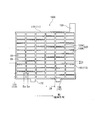
- FIGS. 1A and 1B are plan views showing the appearance of current collectors 100A and 100B that form a positive electrode plate in a lead storage battery according to one embodiment and another embodiment of the present invention, respectively.
- Each of the current collectors 100A and 100B has a frame bone 110 and an internal bone 120 inside the frame bone 110.
- the frame bone 110 connects the upper element 111 that is continuous with the ear 130, the lower element 112 that is opposed to the upper element 111 and that is continuous with the lower protrusion (also called foot) 132, and connects the upper element 111 and the lower element 112.
- the current collector 100A of FIG. 1A has a lower protrusion (also referred to as a foot) 132 that is continuous with the lower element 112.
- the transverse bone extends obliquely with respect to the upper element or the lower element.
- LH represents the inner length of each longitudinal bone per lattice
- LW represents the inner length of each transverse bone per lattice.
- the current collectors 100A and 100B are, for example, punched grids of a drawn sheet of lead or lead alloy, and the drawing direction is the direction indicated by the arrow MD in FIG.
- a cross section C of the vertical bone 120A is a cross section taken along the line IIa-IIa in FIG. 1
- a cross section G of the horizontal bone 120B is a cross section taken along the IIb-IIb line.
- the metal structure of the stretched sheet easily forms a fibrous structure extending in the stretching direction. Therefore, the cross-section C has such a striped pattern of texture.
- the cross-section G may have a pattern due to the cutting of the fibrous structure.
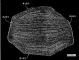
- FIG. 2A is an example of a photograph of a cross section C of the vertical bone 120A, and the cross section has an octagonal shape and a striped pattern of a metal fibrous tissue is seen.
- FIG. 2B is a conceptual diagram of an example of an octagonal cross section C imitating FIG. 2A.
- FIG. 3 is an example of a photograph of a cross section G of the transverse bone 120B, and a pattern of a cross section perpendicular to the fiber length of the metal fibrous structure can be seen in the cross section.
- most of the right and left sides of the octagonal cross section C is the second portion 220, and the other outer peripheral region is the first portion 210.
- the fringes of fibrous tissue form an angle ⁇ 1 of less than 45 ° with the contour of section C (line S1).
- the fringe (tangent S2) has an angle ⁇ 2 that exceeds 45 ° with the contour (line S1) of the cross section C.
- the outermost layer of the second portion 220 has a region in which a striped pattern of fibrous tissue having a thickness of less than about 55 ⁇ m is observed, but such a thin portion constitutes the first portion 210. do not do.
- FIG. 4 is a conceptual view of a cross section C showing the progress of internal bone corrosion.
- the portion where the shallow corrosion layer is formed is the first portion where the fibrous structure extends along the contour of the cross section C, and even if the corrosion progresses, the corrosion layer is difficult to form deep. However, since it is formed of a fibrous structure, peeling tends to occur near the interface between the current collector and the electrode material. Therefore, it is considered that the stress that the current collector is about to deform is easily relieved.
- the portion where the wedge-shaped deep corrosion layer is formed is the second portion. When the deep corrosion layer is formed, the current collector is likely to be unevenly deformed, the current collector is elongated, and the electrode material is likely to drop off.
- the positive electrode plate of the lead storage battery includes the above-described current collector and a positive electrode material held by the current collector (positive electrode current collector).
- a so-called positive electrode plate is used as the positive electrode plate.
- the positive electrode material is obtained by removing the positive electrode current collector from the positive electrode plate.
- Members such as a mat and pasting paper may be attached to the positive electrode plate. Since such a member (sticking member) is used integrally with the positive electrode plate, it is included in the positive electrode plate.
- the positive electrode material excludes the positive electrode current collector and the sticking member.
- the thickness of the attachment member is included in the thickness of the separator.
- the positive electrode current collector is preferably a punched current collector, as described above.
- the current collector has the frame bone, the ear provided on the frame bone, and the internal bone inside the frame bone.
- a grid-shaped current collector (positive electrode grid) is preferable.
- the inner bone portion has a grid shape (including a mesh shape). By using the positive electrode grid, it becomes easy to support the positive electrode material.
- the frame bone is preferably rectangular. The rectangle does not have to be a strict rectangle, and the vertices may be slightly rounded or each side may be slightly bent.
- the positive electrode current collector can be formed by press punching a lead or lead alloy sheet.
- the sheet is preferably a stretched sheet that has been stretched (also referred to as a rolled plate).
- the stretched sheet may be a uniaxially stretched sheet or a biaxially stretched sheet.
- the current collector can be manufactured by a manufacturing method including pressing an intermediate bone that is a precursor of the internal bone.
- a manufacturing method includes, for example, an intermediate grid body having a plurality of intermediate bones formed in a grid shape by (i) preparing a rolled plate and (ii) punching the rolled plate. And (iii) performing a pressing process on the intermediate lattice in the thickness direction of the intermediate lattice to form at least a part of the internal bone.
- at least a part of the plurality of intermediate bones at least one end portion in the bone width direction becomes thinner than the central portion in the bone width direction that intersects (for example, is orthogonal to) the extending direction of the intermediate bones. Including the transformation.
- a Pb-Ca-based alloy, a Pb-Ca-Sn-based alloy, or a Pb-Sn-based alloy is preferable in terms of corrosion resistance and mechanical strength. Further, lead having a purity of three-nine or higher (purity of 99.9 mass% or higher) may be used for the positive electrode current collector.
- the positive electrode current collector may have lead alloy layers having different compositions, and may have a plurality of alloy layers.
- the ratio R2 of the second portion may be less than 50%, preferably 40% or less.
- the lower limit of the ratio R2 is not particularly limited, but is preferably 20% or more, and may be 30% or more, from the viewpoint of easily ensuring the initial adhesion between the positive electrode material and the current collector.
- the positive electrode material contains a positive electrode active material (lead dioxide or lead sulfate) that develops capacity by a redox reaction. Further, the positive electrode material contains at least one selected from the group consisting of Sn and Sb. Sn and Sb are usually included as additives. The positive electrode material may contain an additive other than Sn and / or an additive containing Sn, if necessary.
- a positive electrode active material lead dioxide or lead sulfate
- Sn and Sb are usually included as additives.
- the positive electrode material may contain an additive other than Sn and / or an additive containing Sn, if necessary.
- Examples of the additive containing Sn include metallic tin (Sn), Sn alloys, oxides (tin (II) oxide, tin (IV) oxide, tin oxide (VI), etc.), tin sulfate (SnSO 4 ), and the like.
- Examples of the additive containing Sb include metal antimony (Sb), Sb alloy, antimony trioxide (Sb 2 O 3 ), antimony oxide such as antimony tetroxide and antimony pentoxide, and antimony sulfate (Sb 2 (SO 4 ) 3 ) And the like.
- the lead powder metal Pb may be mixed with an alloy of Pb and Sn, an alloy of Pb and Sb, or an alloy of Pb, Sn and Sb.
- the content c1 of Sn in the positive electrode material may be less than 0.75 mass%, preferably 0.6 mass% or less, more preferably 0.5 mass% or less.
- the content c2 of Sb in the positive electrode material may be less than 0.50% by mass, preferably 0.4% by mass or less, and more preferably 0.3% by mass or less.
- the total c3 of c1 and c2 may be less than 0.8% by mass, and is preferably 0.7% by mass or less.
- c1 is preferably 0.01% by mass or more.
- c2 is preferably 0.01% by mass or more.
- the content of c3 is preferably 0.01% by mass or more, and may be 0.02% by mass or more. When the contents c1, c2 and / or c3 are in such ranges, the effect of suppressing the occurrence of the PCL phenomenon in the heavy load cycle is enhanced and the softening of the positive electrode material can be further suppressed.
- the upper limit value and the lower limit value can be arbitrarily combined.
- the unformed positive electrode plate is obtained by filling a positive electrode current collector with a positive electrode paste, aging and drying. After that, an unformed positive electrode plate is formed.
- the positive electrode paste is prepared by kneading lead powder, additives, water, sulfuric acid and the like.
- the negative electrode plate of the lead storage battery is composed of a current collector and a negative electrode material.
- the negative electrode material is obtained by removing the negative electrode current collector from the negative electrode plate.
- a member such as a mat or pasting paper may be attached to the negative electrode plate. Since such a member (sticking member) is used integrally with the negative electrode plate, it is included in the negative electrode plate.
- the negative electrode material excludes the negative electrode current collector and the sticking member.
- the negative electrode current collector may be formed by casting lead (Pb) or a lead alloy, or may be formed by processing a sheet of lead or a lead alloy. Examples of the processing method include expanding processing and punching processing. It is preferable to use a grid-shaped current collector (negative electrode grid) as the negative electrode current collector because the negative electrode material can be easily carried. As the negative electrode current collector, a current collector as described for the positive electrode current collector may be used.
- the lead alloy used for the negative electrode current collector may be either a Pb-Ca-based alloy or a Pb-Ca-Sn-based alloy. These lead or lead alloy may further contain at least one selected from the group consisting of Ba, Ag, Al, Bi, As, Se, Cu and the like as an additional element.
- the negative electrode material contains, as an essential component, a negative electrode active material (lead or lead sulfate) that develops a capacity by a redox reaction, and may contain additives such as an organic shrinkage inhibitor, a carbonaceous material, and barium sulfate.
- a negative electrode active material lead or lead sulfate
- the negative electrode active material in the charged state is spongy lead, but the unformed negative electrode plate is usually produced by using lead powder.
- At least one selected from the group consisting of lignins and / or synthetic organic stabilizers may be used as the organic stabilizer.
- lignins include lignin and lignin derivatives.
- the lignin derivative include lignin sulfonic acid or salts thereof (alkali metal salts such as sodium salts).
- the synthetic organic anti-shrink agent is an organic polymer containing elemental sulfur, and generally contains a plurality of aromatic rings in the molecule and also contains elemental sulfur as a sulfur-containing group.
- the sulfur-containing groups a stable form of a sulfonic acid group or a sulfonyl group is preferable.
- the sulfonic acid group may be present in an acid form or in a salt form such as Na salt.
- a condensate of a compound having a sulfur-containing group and an aromatic ring with an aldehyde compound is preferable.
- the aromatic ring include a benzene ring and a naphthalene ring.
- the plurality of aromatic rings may be linked by a direct bond or a linking group (for example, an alkylene group, a sulfone group, etc.). Examples of such a structure include biphenyl, bisphenylalkane, and bisphenylsulfone.
- Examples of the compound having an aromatic ring include compounds having the above aromatic ring and a hydroxy group and / or an amino group.
- the hydroxy group or amino group may be directly bonded to the aromatic ring, or may be bonded as an alkyl chain having a hydroxy group or amino group.
- the compound having an aromatic ring is preferably a bisphenol compound, a hydroxybiphenyl compound, a hydroxynaphthalene compound, a phenol compound or the like.
- the compound having an aromatic ring may further have a substituent.
- the organic anti-shrink agent may contain one kind of the residue of these compounds, or may contain plural kinds thereof.
- bisphenol compound bisphenol A, bisphenol S, bisphenol F and the like are preferable.
- the sulfur-containing group may be directly bonded to the aromatic ring contained in the compound, for example, may be bonded to the aromatic ring as an alkyl chain having a sulfur-containing group.
- a condensation product of an aldehyde compound with a compound having an aromatic ring as described above and a monocyclic aromatic compound (aminobenzenesulfonic acid, alkylaminobenzenesulfonic acid, phenolsulfonic acid or a substituted product thereof) is used.
- a monocyclic aromatic compound aminobenzenesulfonic acid, alkylaminobenzenesulfonic acid, phenolsulfonic acid or a substituted product thereof.
- the content of the organic anti-shrink agent contained in the negative electrode material is, for example, preferably 0.01% by mass or more, more preferably 0.02% by mass or more, and further preferably 0.05% by mass or more. On the other hand, 1.0 mass% or less is preferable, 0.8 mass% or less is more preferable, and 0.5 mass% or less is further preferable. These lower limit values and upper limit values can be arbitrarily combined.
- the content of the organic anti-shrink agent contained in the negative electrode material is the content in the negative electrode material collected by the method described below from the already-formed fully charged lead storage battery.
- carbon black As the carbonaceous material contained in the negative electrode material, carbon black, graphite, hard carbon, soft carbon or the like can be used.
- carbon black include acetylene black, furnace black and lamp black.
- Furness black includes Ketjen black (trade name).
- the graphite may be any carbon material having a graphite type crystal structure, and may be either artificial graphite or natural graphite.
- the content of the carbonaceous material in the negative electrode material is, for example, preferably 0.05% by mass or more, and more preferably 0.2% by mass or more. On the other hand, 4.0 mass% or less is preferable, 3 mass% or less is more preferable, and 2 mass% or less is further preferable. These lower limit values and upper limit values can be arbitrarily combined.
- the content of barium sulfate in the negative electrode material is, for example, preferably 0.5% by mass or more, more preferably 1% by mass or more, and further preferably 1.3% by mass or more. On the other hand, 3.0 mass% or less is preferable, 2.5 mass% or less is more preferable, and 2 mass% or less is further preferable. These lower limit values and upper limit values can be arbitrarily combined.
- the lead-acid battery after chemical formation should be fully charged and then disassembled to obtain the negative electrode plate to be analyzed.
- the obtained negative electrode plate is washed with water and dried to remove the electrolytic solution in the negative electrode plate.
- the washing with water is carried out by pressing a pH test paper against the surface of the washed negative electrode plate until it is confirmed that the color of the test paper does not change.
- the time for washing with water is within 2 hours. Is dried in a reduced pressure environment for about 6 hours at 60 ° C. ⁇ 5 ° C. After drying, when the negative electrode plate includes a sticking member, the sticking member is removed from the negative electrode plate by peeling.
- the negative electrode An unground sample S is obtained by separating the negative electrode material from the plate.
- the UV-Visible absorption spectrum of the filtrate to be analyzed The content of the organic shrinkproofing agent in the negative electrode material is quantified using the spectral intensity and the calibration curve prepared in advance. Unable to rigorously specify the structural formula of the organic shrinkage agent to be analyzed, if the calibration curve of the same organic shrinkage agent cannot be used, UV-visible absorption spectrum similar to the organic shrinkage agent to be analyzed, infrared spectrum, A calibration curve is prepared using an organic shrinking agent that is available, showing an NMR spectrum and the like.
- the dispersion liquid is subjected to suction filtration using a membrane filter whose mass has been measured in advance, and the membrane filter is dried together with the filtered sample in a drier at 110 ° C ⁇ 5 ° C.
- the sample filtered out is a mixed sample of carbonaceous material and barium sulfate.
- the mass (A) of the mixed sample is measured by subtracting the mass of the membrane filter from the total mass of the dried mixed sample and the membrane filter.
- the dried mixed sample is put into a crucible together with a membrane filter, and is burnt at a temperature of 700 ° C. or higher.
- the remaining residue is barium oxide.
- the mass of barium oxide is converted into the mass of barium sulfate to obtain the mass (B) of barium sulfate.
- the mass B is subtracted from the mass A to calculate the mass of the carbonaceous material.
- the negative electrode plate can be formed by filling a negative electrode current collector with a negative electrode paste, aging and drying to prepare an unformed negative electrode plate, and then forming the unformed negative electrode plate.
- the negative electrode paste is prepared by adding water and sulfuric acid to lead powder and various additives and kneading. In the aging step, it is preferable to age the unformed negative electrode plate at room temperature or at a higher temperature and higher humidity.
- the formation can be performed by charging the electrode plate group while immersing the electrode plate group including the unformed negative electrode plate in the electrolytic solution containing sulfuric acid in the battery case of the lead storage battery. However, the formation may be performed before the lead storage battery or the electrode plate group is assembled. By formation, spongy lead is produced.
- the electrolytic solution is an aqueous solution containing sulfuric acid, and may be gelled if necessary.
- the specific gravity of the electrolytic solution in the fully charged lead storage battery at 20 ° C. is, for example, 1.20 or more and 1.35 or less, and preferably 1.25 or more and 1.32 or less.
- a separator is usually arranged between the negative electrode plate and the positive electrode plate.
- a nonwoven fabric, a microporous membrane, or the like is used for the separator.
- the thickness and the number of separators interposed between the negative electrode plate and the positive electrode plate may be selected according to the distance between the electrodes.
- Nonwoven fabric is a mat in which fibers are intertwined without weaving, and mainly consists of fibers. For example, 60% by mass or more of the non-woven fabric is formed of fibers.
- the fiber glass fiber, polymer fiber (polyolefin fiber, acrylic fiber, polyester fiber such as polyethylene terephthalate fiber, etc.), pulp fiber and the like can be used. Of these, glass fiber is preferable.
- the non-woven fabric may include components other than fibers, such as acid-resistant inorganic powder and a polymer as a binder.
- the microporous membrane is a porous sheet mainly composed of components other than fiber components, for example, a composition containing a pore-forming agent (polymer powder and / or oil, etc.) is extruded into a sheet and then formed into a pore. Obtained by removing the agent to form pores.
- the microporous membrane is preferably made of a material having acid resistance, and is preferably composed mainly of a polymer component.
- the polymer component polyolefins such as polyethylene and polypropylene are preferable.
- the separator may be composed of, for example, only a non-woven fabric or a microporous film. Further, the separator may be a laminate of a non-woven fabric and a microporous film, a material in which different materials or the same material are bonded together, or a material in which unevenness is meshed with different materials or the same material, as necessary.
- the separator may be formed in a bag shape. In that case, the bag-shaped separator may house the positive electrode plate or the negative electrode plate.
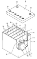
- FIG. 5 shows an external appearance of an example of the lead storage battery according to the embodiment of the present invention.
- the lead storage battery 1 includes a battery case 12 that contains an electrode plate group 11 and an electrolytic solution (not shown).
- the inside of the battery case 12 is partitioned into a plurality of cell chambers 14 by partition walls 13.
- One electrode plate group 11 is housed in each cell chamber 14.
- the opening of the battery case 12 is closed by a lid 15 having a negative electrode terminal 16 and a positive electrode terminal 17.
- the lid 15 is provided with a liquid port stopper 18 for each cell chamber. When replenishing water, the liquid port plug 18 is removed to replenish the replenishing water.
- the liquid port plug 18 may have a function of discharging the gas generated in the cell chamber 14 to the outside of the battery.
- the electrode plate group 11 is configured by laminating a plurality of negative electrode plates 2 and positive electrode plates 3 with separators 4 interposed therebetween.
- the bag-shaped separator 4 that accommodates the negative electrode plate 2 is shown, but the form of the separator is not particularly limited.
- the negative electrode shelf 6 for connecting the plurality of negative electrode plates 2 in parallel is connected to the through-connecting body 8 and the positive electrode shelf for connecting the plurality of positive electrode plates 3 in parallel. 5 is connected to the positive pole 7.
- the positive pole 7 is connected to a positive terminal 17 outside the lid 15.
- the negative pole 9 is connected to the negative shelf 6 and the through-connector 8 is connected to the positive shelf 5.
- the negative pole 9 is connected to a negative terminal 16 outside the lid 15.
- Each penetrating body 8 passes through a through hole provided in the partition wall 13 to connect the electrode plate groups 11 of the adjacent cell chambers 14 in series.
- FIG. 5 shows an example of a liquid type battery (vent type battery), but the lead storage battery may be a control valve type battery (VRLA type).
- the lead storage battery may be a control valve type battery (VRLA type).
- VRLA type control valve type battery
- the above embodiment of the present invention is particularly suitable for the liquid type battery.
- the life performance in the heavy load cycle is evaluated as follows. JIS D 5301: 2006 9.5.5 Life test b) A heavy load test is performed based on the heavy load life test. More specifically, first, the lead-acid battery in a fully charged state is discharged at the discharge current shown in Table 1 for 1 hour, and then at the charge current shown in Table 1 for 5 hours. This cycle of discharging and charging is one cycle. The discharge current and the discharge current are changed as shown in Table 1 according to the 5-hour rate capacity of the lead storage battery.
- the following description of the heavy load test is an example of using a lead storage battery (12 V) having a 5-hour rate capacity of 48 Ah. During the test, the lead-acid battery is placed in a water bath at 40 ° C ⁇ 2 ° C.
- the water surface of the water tank is located 15 mm to 25 mm below the upper surface of the storage battery.
- the distance between adjacent lead storage batteries and the distance to the inner wall of the water tank adjacent to the lead storage batteries should be at least 25 mm.
- the capacity (Ah) obtained from the product of the discharge time and the discharge current measured in the above test decreases to 50% or less of the rated capacity of 48 Ah and does not increase again, and the test ends.
- the number of times that the capacity becomes 50% of the rated capacity of 48 Ah (the number of times of life) is used as an index of life performance in a heavy load cycle.
- the fact that the capacity does not rise again is determined from the product of the discharge time and the discharge current at this time, after the capacity has dropped to 50% of the rated capacity, the battery is charged to the fully charged state, and the same discharge as above is performed again. Check based on the capacity being 50% or less of the rated capacity.
- the number of lifespans can be obtained by approximating the number of cycles at 50% of the rated capacity from the graph of the number of cycles and the capacity in which the discharge capacity is plotted every 25 cycles.
- the number of cycles at this time is determined to be the life due to liquid reduction.
- the number of cycles when the liquid level of the electrolytic solution is lowered to the upper end of the positive electrode strap (positive electrode shelf) is determined to be the life due to liquid reduction.
- the lead-acid batteries according to one aspect of the present invention are collectively described below.
- One aspect of the present invention is a lead acid battery, A positive electrode plate, a negative electrode plate, and an electrolytic solution
- the positive electrode plate includes a current collector and a positive electrode material held by the current collector
- the current collector has a frame bone, an ear provided in the frame bone, and an internal bone inside the frame bone
- the frame bone comprises an upper element continuous with the ear, a lower element facing the upper element, and a pair of side elements connecting the upper element and the lower element
- the internal bone comprises a longitudinal bone extending in a first direction from the upper element toward the lower element, and a horizontal bone extending in a second direction from one side element toward the other side element,
- a striped pattern of metallic fibrous tissue is seen
- the outer peripheral region of the cross section is composed of a first portion in which the fibrous tissue extends along the contour of the cross section, and a second portion other than the first portion,
- the ratio R2 is preferably 40% or less.
- the ratio R2 is preferably 30% or less.
- the ratio R2 is preferably 20% or more.
- the ratio R2 is preferably 30% or more.
- the content c1 is preferably 0.6% by mass or less. (7) In any one of the above (1) to (6), the content c1 is preferably 0.5% by mass or less. (8) In any one of the above (1) to (7), the content c1 is preferably 0.01% by mass or more.
- the content c2 is preferably 0.4% by mass or less. (10) In any one of the above (1) to (9), the content c2 is preferably 0.3% by mass or less. (11) In any one of the above (1) to (10), the content c2 is preferably 0.01% by mass or more.
- the total c3 is preferably 0.7% by mass or less. (13) In any one of the above (1) to (12), the total c3 is preferably 0.01% by mass or more. (14) In any one of the above (1) to (13), the total c3 is preferably 0.02 mass% or more.
- the positive electrode material preferably contains at least Sn.
- the density of the positive electrode material is preferably 3.4 g / cm 3 or more.
- the density of the positive electrode material is preferably 4.8 g / cm 3 or less.
- the density of the positive electrode material is preferably 4.6 g / cm 3 or less.
- the cross section is preferably octagonal.
- the current collector is preferably a punched current collector of a drawn sheet of lead or lead alloy.
- the total length WLH of the inner bone of the longitudinal bone and the total length WLW of the inner bone of the transverse bone satisfy WLH / WLW ⁇ 0.8.
- WLH / WLW ⁇ 1.3 is satisfied.
- the thickness of the internal bone is preferably 0.7 mm or more.
- the thickness of the internal bone is preferably 3 mm or less.
- the bone width of the internal bone is preferably 0.7 mm or more.
- the bone width of the internal bone is preferably 3 mm or less.
- the thickness of the first portion in the cross section C is preferably 55 ⁇ m or more.
- the process of preparing the current collector is A step of preparing a rolled plate, Performing a punching process on the rolled plate to form an intermediate lattice body having a plurality of intermediate bones formed in a lattice shape; A step of forming at least a part of the internal bone by performing a pressing process on the intermediate lattice in the thickness direction of the intermediate lattice, In the press working, in at least a part of the plurality of intermediate bones, at least one end portion in the bone width direction becomes thinner than the central portion in the bone width direction intersecting the extending direction of the intermediate bones, and the ratio R2 is 50%. It includes deforming to be less than.
- a positive electrode paste containing lead powder and an Sn additive and / or an Sb additive is prepared, and the positive electrode paste is filled in the grid portion of the current collector, aged, and dried.
- a chemical conversion positive electrode plate is prepared. The filling amount of the positive electrode paste is adjusted so that the density of the positive electrode material after chemical conversion is 4.2 g / cm 3 .
- the Sn additive and / or the Sb additive are added so that the Sn and Sb contents c1 and c2 obtained by the above-described procedure become the values shown in Table 2, respectively. .
- the Sn additive and the Sb additive tin sulfate and antimony trioxide are used, respectively.
- Negative Electrode Plate Lead powder, water, dilute sulfuric acid, barium sulfate, carbon black and an organic shrinkage inhibitor (sodium lignin sulfonate) are mixed to prepare a negative electrode paste.
- An expanding grid made of a Pb-Ca-Sn based alloy as a negative electrode current collector is filled with a negative electrode paste and aged and dried to obtain an unformed negative electrode plate.
- Each unformed negative electrode plate is housed in a bag-shaped separator, and an electrode group is formed by 7 unformed negative electrode plates and 6 unformed positive electrode plates per cell. Insert the electrode group into a polypropylene battery case, inject the electrolytic solution, and perform chemical formation in the battery case to obtain a liquid lead acid battery A1 with a nominal voltage of 12 V and a rated capacity of 48 Ah (5 hour rate). Assemble ⁇ A13 and B1 ⁇ B12. As the electrolytic solution, a sulfuric acid aqueous solution having a specific gravity of 1.28 at 20 ° C. is used.
- the ratio R2 is less than 50%, when the positive electrode material does not contain Sn and Sb, the number of heavy duty cycles is reduced to 70 compared with the lead storage battery B1 (lead storage batteries B9 and B11). This is because although the elongation and distortion of the current collector during the heavy load cycle are suppressed, the adhesion itself between the positive electrode material and the current collector during the initial and heavy load cycles is reduced, so that the vicinity of the positive electrode current collector is reduced. It is considered that the PCL phenomenon occurred due to the accumulation of lead sulfate in the. On the other hand, when the ratio R2 is less than 50% and the positive electrode material containing a specific content of Sn and / or Sb is used, the number of heavy duty cycles is significantly improved to 360.
- Lead storage batteries A14 to A18 and lead storage batteries B13 to B15 >> The Sn additive and / or the Sb additive are added so that the contents c1 and c2 of Sn and Sb become the values shown in Table 3, respectively. Except for these, a positive electrode plate is prepared and lead storage batteries A14 to A18 and B13 to B15 are assembled in the same manner as the lead storage battery A1, and a heavy load test is performed. Table 3 shows the results of the lead storage batteries A14 to A18 and B13 to B15. Table 3 also shows the results of the lead storage batteries A1 to A6, B9, and B10.
- the positive electrode material contains Sn, and the content c1 of Sn is less than 0.75% by mass, the number of heavy load cycles is as high as 360. Lifetime performance can be obtained.
- the positive electrode material contains Sn and the Sn content c1 is 0.75 mass% or more, the number of heavy load cycles decreases. This is because the amount of liquid reduction increased due to gas generation.
- the positive electrode material contains Sb, and the Sb content c2 is less than 0.50 mass%, the number of heavy load cycles is 360 and high life performance is obtained.
- the positive electrode material contains Sb, when the content c2 of Sb is 0.50 mass% or more, the liquid reduction due to gas generation becomes remarkable, and the heavy load cycle life is reduced.
- the lower limit of the content c3 of the additives Sn and Sb is preferably 0.01% by mass or more. Further, for the same reason, the lower limits of the respective contents c1 and c2 of Sn and Sb are preferably 0.01% by mass or more, and the contents c1 and c2 are 0.5% by mass or less and It is preferably 0.3% by mass or less, and c3 is preferably 0.7% by mass or less.
- Lead storage batteries A19 to A24 and lead storage batteries B16 to B17 When manufacturing the positive electrode plate, the filling amount of the positive electrode paste is adjusted so that the density of the positive electrode material after chemical conversion becomes the value shown in Table 4. Further, the Sn additive and / or the Sb additive are added so that the contents c1 and c2 of Sn and Sb become the values shown in Table 4, respectively. Except for these, a positive electrode plate is prepared and lead storage batteries A19 to A24 and B16 to B17 are assembled in the same manner as the lead storage battery A1, and a heavy load test is performed. Table 4 shows the results of the lead storage batteries A19 to A24 and B16 to B17. Table 4 also shows the results of the lead storage batteries A1 to A6, B9, and B10.
- the conductive network is likely to be divided in the positive electrode material, so that the number of heavy load cycles tends to decrease.
- R2 ⁇ 50% and using a positive electrode material containing a specific amount of Sn and / or Sb the elongation and distortion of the current collector can be suppressed, and the durability of the positive electrode material is improved.
- the effect of the conductive path due to and / or Sb is easily exhibited, and high conductivity between the current collector and the positive electrode material is easily secured. Therefore, this high conductivity compensates for the lack of conductivity in the positive electrode material, and high life performance in a heavy load cycle can be secured even when the positive electrode material has a low density.
- the lead storage battery according to the above aspect of the present invention is applicable to control valve type and liquid type lead storage batteries, and is used as a starting power source for vehicles (automobiles, motorcycles, etc.) and industrial power storage for electric vehicles (forklifts, etc.). It can be suitably used as a power source for devices and the like.
- Negative electrode plate 3 Positive electrode plate 4: Separator 5: Positive electrode shelf portion 6: Negative electrode shelf portion 7: Positive electrode column 8: Through connection body 9: Negative electrode column 11: Electrode plate group 12: Battery case 13: Partition wall 14: Cell chamber 15: Lid 16: Negative electrode terminal 17: Positive electrode terminal 18: Liquid mouth plug 100A, 100B: Current collector 110: Frame bone 111: Upper element 112: Lower element 113, 114: Side element 120: Internal bone 120A, B1: Vertical bone 120B: Horizontal bone 130: Ear 132: Lower protrusion (foot) 210: First part of longitudinal bone 220: Second part of longitudinal bone
Landscapes
- Chemical & Material Sciences (AREA)
- Chemical Kinetics & Catalysis (AREA)
- Electrochemistry (AREA)
- General Chemical & Material Sciences (AREA)
- Engineering & Computer Science (AREA)
- Materials Engineering (AREA)
- Manufacturing & Machinery (AREA)
- Inorganic Chemistry (AREA)
- Cell Electrode Carriers And Collectors (AREA)
- Battery Electrode And Active Subsutance (AREA)
Priority Applications (3)
| Application Number | Priority Date | Filing Date | Title |
|---|---|---|---|
| CN201980068152.6A CN112868115A (zh) | 2018-10-16 | 2019-10-16 | 铅蓄电池 |
| EP19873078.0A EP3855537A4 (en) | 2018-10-16 | 2019-10-16 | Lead storage battery |
| JP2020553244A JP7347438B2 (ja) | 2018-10-16 | 2019-10-16 | 鉛蓄電池 |
Applications Claiming Priority (2)
| Application Number | Priority Date | Filing Date | Title |
|---|---|---|---|
| JP2018194795 | 2018-10-16 | ||
| JP2018-194795 | 2018-10-16 |
Publications (1)
| Publication Number | Publication Date |
|---|---|
| WO2020080419A1 true WO2020080419A1 (ja) | 2020-04-23 |
Family
ID=70283831
Family Applications (1)
| Application Number | Title | Priority Date | Filing Date |
|---|---|---|---|
| PCT/JP2019/040715 Ceased WO2020080419A1 (ja) | 2018-10-16 | 2019-10-16 | 鉛蓄電池 |
Country Status (4)
| Country | Link |
|---|---|
| EP (1) | EP3855537A4 (https=) |
| JP (1) | JP7347438B2 (https=) |
| CN (1) | CN112868115A (https=) |
| WO (1) | WO2020080419A1 (https=) |
Cited By (5)
| Publication number | Priority date | Publication date | Assignee | Title |
|---|---|---|---|---|
| CN112103513A (zh) * | 2020-09-17 | 2020-12-18 | 超威电源集团有限公司 | 一种铅酸蓄电池的正极板、负极板及制造方法 |
| WO2021210244A1 (ja) * | 2020-04-14 | 2021-10-21 | 株式会社Gsユアサ | 鉛蓄電池用集電体、鉛蓄電池用正極板、および鉛蓄電池 |
| WO2022113635A1 (ja) * | 2020-11-27 | 2022-06-02 | 株式会社Gsユアサ | 鉛蓄電池 |
| JP2023071228A (ja) * | 2021-11-11 | 2023-05-23 | 古河電池株式会社 | 液式鉛蓄電池 |
| JP2024044862A (ja) * | 2022-09-21 | 2024-04-02 | エナジーウィズ株式会社 | 鉛蓄電池 |
Families Citing this family (1)
| Publication number | Priority date | Publication date | Assignee | Title |
|---|---|---|---|---|
| WO2025162586A1 (de) * | 2024-02-01 | 2025-08-07 | Hoppecke Batterien Gmbh & Co. Kg | Akkumulatorzelle und blei-säure-akkumulator |
Citations (9)
| Publication number | Priority date | Publication date | Assignee | Title |
|---|---|---|---|---|
| JPS5160936A (ja) | 1974-11-01 | 1976-05-27 | Furukawa Electric Co Ltd | Namarichikudenchonamarikoshiban |
| JPH06267544A (ja) * | 1993-03-12 | 1994-09-22 | Matsushita Electric Ind Co Ltd | 鉛蓄電池用極板とこれを用いた鉛蓄電池 |
| JP2003142147A (ja) * | 2001-10-31 | 2003-05-16 | Japan Storage Battery Co Ltd | 鉛蓄電池 |
| JP2005056622A (ja) * | 2003-08-08 | 2005-03-03 | Japan Storage Battery Co Ltd | 鉛蓄電池用格子の製造方法および鉛蓄電池 |
| WO2012043556A1 (ja) * | 2010-09-29 | 2012-04-05 | 株式会社Gsユアサ | 鉛蓄電池及びこれを用いたアイドリングストップ車 |
| JP2013122838A (ja) * | 2011-12-09 | 2013-06-20 | Furukawa Battery Co Ltd:The | 鉛蓄電池用の正極格子体 |
| JP2015038860A (ja) | 2013-07-19 | 2015-02-26 | 株式会社Gsユアサ | 液式鉛蓄電池及び液式鉛蓄電池を用いたアイドリングストップ車 |
| WO2015056417A1 (ja) * | 2013-10-15 | 2015-04-23 | 株式会社Gsユアサ | 制御弁式鉛蓄電池 |
| JP2017139215A (ja) * | 2016-02-02 | 2017-08-10 | 株式会社Gsユアサ | 鉛蓄電池用の正極板、鉛蓄電池、鉛蓄電池用の正極板の製造方法 |
Family Cites Families (1)
| Publication number | Priority date | Publication date | Assignee | Title |
|---|---|---|---|---|
| EP2747179B1 (en) * | 2012-09-10 | 2017-09-27 | GS Yuasa International Ltd. | Lattice for storage battery, method for producing lattice for storage battery, and storage battery using lattice for storage battery |
-
2019
- 2019-10-16 JP JP2020553244A patent/JP7347438B2/ja active Active
- 2019-10-16 EP EP19873078.0A patent/EP3855537A4/en active Pending
- 2019-10-16 WO PCT/JP2019/040715 patent/WO2020080419A1/ja not_active Ceased
- 2019-10-16 CN CN201980068152.6A patent/CN112868115A/zh active Pending
Patent Citations (10)
| Publication number | Priority date | Publication date | Assignee | Title |
|---|---|---|---|---|
| JPS5160936A (ja) | 1974-11-01 | 1976-05-27 | Furukawa Electric Co Ltd | Namarichikudenchonamarikoshiban |
| JPH06267544A (ja) * | 1993-03-12 | 1994-09-22 | Matsushita Electric Ind Co Ltd | 鉛蓄電池用極板とこれを用いた鉛蓄電池 |
| JP2003142147A (ja) * | 2001-10-31 | 2003-05-16 | Japan Storage Battery Co Ltd | 鉛蓄電池 |
| JP2005056622A (ja) * | 2003-08-08 | 2005-03-03 | Japan Storage Battery Co Ltd | 鉛蓄電池用格子の製造方法および鉛蓄電池 |
| WO2012043556A1 (ja) * | 2010-09-29 | 2012-04-05 | 株式会社Gsユアサ | 鉛蓄電池及びこれを用いたアイドリングストップ車 |
| JP2016225302A (ja) | 2010-09-29 | 2016-12-28 | 株式会社Gsユアサ | 鉛蓄電池及びこれを用いたアイドリングストップ車 |
| JP2013122838A (ja) * | 2011-12-09 | 2013-06-20 | Furukawa Battery Co Ltd:The | 鉛蓄電池用の正極格子体 |
| JP2015038860A (ja) | 2013-07-19 | 2015-02-26 | 株式会社Gsユアサ | 液式鉛蓄電池及び液式鉛蓄電池を用いたアイドリングストップ車 |
| WO2015056417A1 (ja) * | 2013-10-15 | 2015-04-23 | 株式会社Gsユアサ | 制御弁式鉛蓄電池 |
| JP2017139215A (ja) * | 2016-02-02 | 2017-08-10 | 株式会社Gsユアサ | 鉛蓄電池用の正極板、鉛蓄電池、鉛蓄電池用の正極板の製造方法 |
Cited By (9)
| Publication number | Priority date | Publication date | Assignee | Title |
|---|---|---|---|---|
| WO2021210244A1 (ja) * | 2020-04-14 | 2021-10-21 | 株式会社Gsユアサ | 鉛蓄電池用集電体、鉛蓄電池用正極板、および鉛蓄電池 |
| CN112103513A (zh) * | 2020-09-17 | 2020-12-18 | 超威电源集团有限公司 | 一种铅酸蓄电池的正极板、负极板及制造方法 |
| WO2022113635A1 (ja) * | 2020-11-27 | 2022-06-02 | 株式会社Gsユアサ | 鉛蓄電池 |
| JPWO2022113635A1 (https=) * | 2020-11-27 | 2022-06-02 | ||
| JP7687348B2 (ja) | 2020-11-27 | 2025-06-03 | 株式会社Gsユアサ | 鉛蓄電池 |
| US12586821B2 (en) | 2020-11-27 | 2026-03-24 | Gs Yuasa International Ltd. | Lead-acid battery |
| JP2023071228A (ja) * | 2021-11-11 | 2023-05-23 | 古河電池株式会社 | 液式鉛蓄電池 |
| JP7755975B2 (ja) | 2021-11-11 | 2025-10-17 | 古河電池株式会社 | 液式鉛蓄電池 |
| JP2024044862A (ja) * | 2022-09-21 | 2024-04-02 | エナジーウィズ株式会社 | 鉛蓄電池 |
Also Published As
| Publication number | Publication date |
|---|---|
| JPWO2020080419A1 (ja) | 2021-09-09 |
| EP3855537A4 (en) | 2022-08-03 |
| CN112868115A (zh) | 2021-05-28 |
| EP3855537A1 (en) | 2021-07-28 |
| JP7347438B2 (ja) | 2023-09-20 |
Similar Documents
| Publication | Publication Date | Title |
|---|---|---|
| JP7347438B2 (ja) | 鉛蓄電池 | |
| JP7248034B2 (ja) | 鉛蓄電池、および、鉛蓄電池の製造方法 | |
| JPWO2019188056A1 (ja) | 鉛蓄電池 | |
| JP7318660B2 (ja) | 鉛蓄電池 | |
| JP7264175B2 (ja) | 鉛蓄電池 | |
| JP7347439B2 (ja) | 鉛蓄電池 | |
| JPWO2019021690A1 (ja) | 鉛蓄電池 | |
| JP7248033B2 (ja) | 鉛蓄電池およびその製造方法 | |
| WO2019087679A1 (ja) | 鉛蓄電池 | |
| CN111279543A (zh) | 铅蓄电池 | |
| JP7601092B2 (ja) | 鉛蓄電池用集電体、鉛蓄電池用正極板、および鉛蓄電池 | |
| WO2020080424A1 (ja) | 鉛蓄電池用集電体およびその製造方法 | |
| JP7099448B2 (ja) | 鉛蓄電池 | |
| JP2021103630A (ja) | 蓄電池用集電体および電極板 | |
| JP7797970B2 (ja) | 鉛蓄電池 | |
| JP7722170B2 (ja) | 鉛蓄電池 | |
| WO2024005041A1 (ja) | 鉛蓄電池 |
Legal Events
| Date | Code | Title | Description |
|---|---|---|---|
| 121 | Ep: the epo has been informed by wipo that ep was designated in this application |
Ref document number: 19873078 Country of ref document: EP Kind code of ref document: A1 |
|
| ENP | Entry into the national phase |
Ref document number: 2020553244 Country of ref document: JP Kind code of ref document: A |
|
| WWE | Wipo information: entry into national phase |
Ref document number: 2101002185 Country of ref document: TH |
|
| NENP | Non-entry into the national phase |
Ref country code: DE |
|
| ENP | Entry into the national phase |
Ref document number: 2019873078 Country of ref document: EP Effective date: 20210420 |