WO2020071179A1 - サポートビーム - Google Patents
サポートビームInfo
- Publication number
- WO2020071179A1 WO2020071179A1 PCT/JP2019/037324 JP2019037324W WO2020071179A1 WO 2020071179 A1 WO2020071179 A1 WO 2020071179A1 JP 2019037324 W JP2019037324 W JP 2019037324W WO 2020071179 A1 WO2020071179 A1 WO 2020071179A1
- Authority
- WO
- WIPO (PCT)
- Prior art keywords
- web
- flange
- arm
- support beam
- region
- Prior art date
- Legal status (The legal status is an assumption and is not a legal conclusion. Google has not performed a legal analysis and makes no representation as to the accuracy of the status listed.)
- Ceased
Links
Images





Classifications
-
- B—PERFORMING OPERATIONS; TRANSPORTING
- B62—LAND VEHICLES FOR TRAVELLING OTHERWISE THAN ON RAILS
- B62D—MOTOR VEHICLES; TRAILERS
- B62D21/00—Understructures, i.e. chassis frame on which a vehicle body may be mounted
- B62D21/11—Understructures, i.e. chassis frame on which a vehicle body may be mounted with resilient means for suspension, e.g. of wheels or engine; sub-frames for mounting engine or suspensions
-
- B—PERFORMING OPERATIONS; TRANSPORTING
- B60—VEHICLES IN GENERAL
- B60G—VEHICLE SUSPENSION ARRANGEMENTS
- B60G11/00—Resilient suspensions characterised by arrangement, location or kind of springs
- B60G11/26—Resilient suspensions characterised by arrangement, location or kind of springs having fluid springs only, e.g. hydropneumatic springs
- B60G11/28—Resilient suspensions characterised by arrangement, location or kind of springs having fluid springs only, e.g. hydropneumatic springs characterised by means specially adapted for attaching the spring to axle or sprung part of the vehicle
-
- F—MECHANICAL ENGINEERING; LIGHTING; HEATING; WEAPONS; BLASTING
- F16—ENGINEERING ELEMENTS AND UNITS; GENERAL MEASURES FOR PRODUCING AND MAINTAINING EFFECTIVE FUNCTIONING OF MACHINES OR INSTALLATIONS; THERMAL INSULATION IN GENERAL
- F16F—SPRINGS; SHOCK-ABSORBERS; MEANS FOR DAMPING VIBRATION
- F16F1/00—Springs
- F16F1/02—Springs made of steel or other material having low internal friction; Wound, torsion, leaf, cup, ring or the like springs, the material of the spring not being relevant
- F16F1/18—Leaf springs
- F16F1/185—Leaf springs characterised by shape or design of individual leaves
-
- B—PERFORMING OPERATIONS; TRANSPORTING
- B60—VEHICLES IN GENERAL
- B60G—VEHICLE SUSPENSION ARRANGEMENTS
- B60G2202/00—Indexing codes relating to the type of spring, damper or actuator
- B60G2202/10—Type of spring
- B60G2202/15—Fluid spring
- B60G2202/152—Pneumatic spring
- B60G2202/1524—Pneumatic spring with two air springs per wheel, arranged before and after the wheel axis
-
- B—PERFORMING OPERATIONS; TRANSPORTING
- B60—VEHICLES IN GENERAL
- B60G—VEHICLE SUSPENSION ARRANGEMENTS
- B60G2204/00—Indexing codes related to suspensions per se or to auxiliary parts
- B60G2204/10—Mounting of suspension elements
- B60G2204/12—Mounting of springs or dampers
- B60G2204/126—Mounting of pneumatic springs
-
- B—PERFORMING OPERATIONS; TRANSPORTING
- B60—VEHICLES IN GENERAL
- B60G—VEHICLE SUSPENSION ARRANGEMENTS
- B60G2206/00—Indexing codes related to the manufacturing of suspensions: constructional features, the materials used, procedures or tools
- B60G2206/01—Constructional features of suspension elements, e.g. arms, dampers, springs
- B60G2206/014—Constructional features of suspension elements, e.g. arms, dampers, springs with reinforcing nerves or branches
-
- B—PERFORMING OPERATIONS; TRANSPORTING
- B60—VEHICLES IN GENERAL
- B60G—VEHICLE SUSPENSION ARRANGEMENTS
- B60G2206/00—Indexing codes related to the manufacturing of suspensions: constructional features, the materials used, procedures or tools
- B60G2206/01—Constructional features of suspension elements, e.g. arms, dampers, springs
- B60G2206/10—Constructional features of arms
- B60G2206/121—Constructional features of arms the arm having an H or X-shape
Definitions
- the present invention relates to a support beam provided on a vehicle such as a truck, a bus, and an automobile.
- support beams are important undercarriage parts that connect the body and axle.
- the support beam is arranged near the rear wheel of the vehicle and supports the vehicle body.
- Patent Document 1 Japanese Unexamined Patent Application Publication No. 11-314511
- Patent Document 2 Japanese Utility Model Application Laid-Open No. 3-71907
- Patent Document 3 Japanese Utility Model Application Laid-Open No. 3-78614
- the support beam includes a first support, a second support, and an arm. The arm connects the first support and the second support.
- the axle cover that supports the axle is fixed on the first support.
- An air spring attached to the vehicle body is fixed on the second support.
- the number of the second support portions and the arms is two.
- the two second support portions are arranged in the front-rear direction of the vehicle (hereinafter, also referred to as “vehicle length direction”) such that the first support portions are arranged between each other. Accordingly, each of the two arms extends in the vehicle length direction from the first support portion.
- a plurality of air springs are provided at intervals from each other in the vehicle body in order to suppress the ride comfort and vibration to the loaded luggage, and to keep the vehicle height constant when the vehicle is loaded or empty.
- a support beam is used as a suspension member for connecting the vehicle body and the axle via an air spring.
- the support beam is constantly loaded in the vertical direction of the vehicle (hereinafter, also referred to as “vehicle height direction”). Furthermore, a load in the vehicle length direction or a load in the vehicle width direction (hereinafter, also referred to as “vehicle width direction”) may be applied to the support beam. Therefore, a bending load in the vehicle height direction is always applied to the arm of the support beam. Further, a bending load in the vehicle width direction may be applied to the arm.
- One of the measures to suppress the deformation of the support beam is to increase the rigidity of the support beam (particularly, the rigidity of the arm in the vehicle height direction).
- the rigidity per mass of the support beam can be increased, a lighter support beam and a more compact support beam can be realized. Reducing the weight of the support beam is beneficial for improving fuel efficiency. Further, around the support beam, the vehicle body, axles, wheels, and other components are densely packed. Support beam compaction is beneficial in preventing the support beams from interfering with their surrounding components.
- Patent Documents 1 to 4 attention is not paid to increasing the rigidity of the support beam.
- JP-A-11-314511 Japanese Utility Model Publication No. 3-71907 Japanese Utility Model Publication No. 3-78614 JP-A-9-99720
- One object of the present invention is to provide a support beam having high rigidity per mass.
- a support beam includes a first support portion, a second support portion, and an arm connecting the first support portion and the second support portion.
- the arm includes a web and a flange.
- the flange includes a first end, a second end, and a center. The center of the flange leads to the end of the web.
- the flange includes, in a cross section of the arm, a bend in a region between the first end and the second end, wherein a center line of the thickness of the flange is bent outward in the extending direction of the web.
- FIG. 1 is a side view schematically illustrating an example of a support beam.
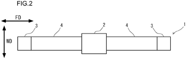
- FIG. 2 is a plan view schematically showing an example of the support beam.
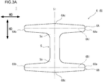
- FIG. 3A is a cross-sectional view schematically illustrating an example of an actual arm shape.
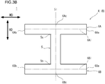
- FIG. 3B is a cross-sectional view schematically illustrating an example of a simplified arm shape.
- FIG. 4A is a cross-sectional view schematically illustrating an example of the arm in the support beam according to the present embodiment.
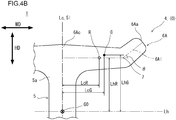
- FIG. 4B is a cross-sectional view schematically illustrating an example of the arm in the support beam of the present embodiment.
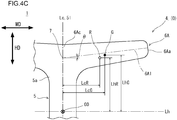
- FIG. 4C is a cross-sectional view schematically illustrating an example of the arm in the support beam of the present embodiment.
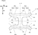
- FIG. 5 is a cross-sectional view schematically illustrating an example of the arm in the support beam according to the present embodiment.
- FIG. 6 is a cross-sectional view schematically illustrating an example of the arm in the support beam of the present embodiment.
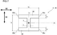
- FIG. 7 is a schematic diagram illustrating a cross-sectional shape of an arm of a model B as a comparative example.
- FIG. 8 is a schematic diagram showing the cross-sectional shape of the arm of the model O which is an example of the present invention.
- FIG. 9 is a diagram summarizing the second moment of area for the model B.
- FIG. 10 is a diagram summarizing the second moment of area for the model O.
- the support beam of the present embodiment includes a first support, a second support, and an arm connecting the first support and the second support.
- the arm includes a web and a flange.
- the flange includes a first end, a second end, and a center. The center of the flange leads to the end of the web.
- the flange includes a bend in a cross section of the arm in a region between the first end and the second end, in which a center line of the thickness of the flange bends outward in the direction in which the web extends (first). Constitution).
- the support beam arm of the present embodiment may be referred to as an arm (O).
- the support beams are mounted on a vehicle and arranged in the orientation in use. It means the direction in the state where it was done.
- the vertical direction of the vehicle that is, the vehicle height direction corresponds to the vertical direction of the support beam arm.
- the longitudinal direction of the vehicle that is, the vehicle length direction corresponds to the longitudinal direction of the support beam arm.
- the web extends in the vehicle height direction. That is, the extending direction of the web coincides with the vehicle height direction.
- the flange extends in the left-right direction of the vehicle, that is, in the vehicle width direction. That is, the extending direction of the flange coincides with the vehicle width direction.
- an axle cover that supports the axle is fixed on the first support portion.
- An air spring attached to the vehicle body is fixed on the second support.
- the flange since the flange includes a bent portion, the flange is bent from both the central axis of the web extending direction (vehicle height direction) and the central axis of the flange extending direction (vehicle width direction).
- the material is located at a remote location.
- the former center axis of the bending in the vehicle height direction corresponds to a straight line perpendicular to the center line of the web thickness in the cross section of the arm.
- the latter center axis of the bending in the vehicle width direction corresponds to the center line of the thickness in the cross section of the arm. Therefore, the secondary moment of area of the cross section of the arm (O) increases in both the vehicle height direction and the vehicle width direction. This increases the rigidity of the arm (O) in both the vehicle height direction and the vehicle width direction. And as a result, weight reduction can be realized. Further, the outer dimensions of the cross section of the arm (O) can be made compact.
- each of the two ends of the web is provided with a flange.
- the flange may be provided only at one of the two ends of the web. From the viewpoint of increasing the rigidity of the arm (O), it is preferable that a flange is provided at each of the two ends of the web. That is, the number of flanges is preferably two.
- One bent portion may be provided on one flange, two bent portions may be provided, or three or more bent portions may be provided.
- a bend is provided in one flange in each of a region between the first end and the central portion and a region between the second end and the central portion.
- the cross-sectional shape of the flange provided with the bent portion is symmetric about the center line of the web thickness.
- the bent portion may be provided on only one of the two flanges, or may be provided on both of the two flanges. From the viewpoint of increasing the rigidity of the arm (O), it is preferable that bent portions are provided on both of the two flanges.
- the number of the second support portions and the arms (O) is two.
- the two second support portions are arranged in the vehicle length direction (the front-rear direction of the vehicle) such that the first support portions are arranged between each other.
- the two arms (O) each extend from the first support portion in the vehicle length direction. That is, the longitudinal direction of the arm (O) is along the vehicle length direction.
- one arm (O) extends forward from the first support, and the other arm (O) extends rearward from the first support.
- the two arms (O) do not need to strictly extend in the vehicle length direction from the first support portion. That is, the longitudinal direction of the arm (O) may be substantially along the vehicle length direction. Further, the longitudinal directions of the two arms (O) do not need to coincide with each other.
- the number of the second support portions and the arms (O) may be one, or may be three or more.
- the cross-sectional shape (dimensions such as outer shape and plate thickness) of the arm (O) is constant in the longitudinal direction of the arm (O).
- the cross-sectional shape of the arm (O) may change in the longitudinal direction of the arm (O).
- the bending moment acting on the arm (O) is larger as it is closer to the first support portion that is a fixed point. Therefore, it is preferable that the cross-sectional shape of the arm (O) is larger near the first support portion than near the second support portion. In this case, in order to prevent stress concentration, it is preferable that the change in the cross-sectional shape of the arm (O) in the longitudinal direction is gentle.
- the arm (O) curves along the longitudinal direction of the arm (O) like a curved beam.
- the arm (O) may be straight like a straight beam.
- curved beams have higher rigidity than straight beams. From the viewpoint of increasing the rigidity, an arm (O) curved so as to be convex downward in the vehicle height direction is preferable.
- the arm (O) may be provided with a mounting seat such as a vibration damper.
- the flange preferably further includes a first thin portion (second configuration).
- the flange preferably further includes a second thin portion (third configuration).
- the first thin portion and the bent portion are arranged in a first central region located on the web side in a region between the first end and the central portion in the cross section of the arm.
- the first central region is 50% of the distance from the center line of the web thickness to the first end.
- the thickness of the first thin portion is smaller than the maximum thickness of a region located outside the first central region.
- the second thin portion and the bent portion are disposed in a second central region located on the web side in a region between the second end and the central portion in the cross section of the arm.
- the second central region is 50% of the distance from the center line of the web thickness to the second end.
- the thickness of the second thin portion is smaller than the maximum thickness of a region located outside the second central region.
- the thin portion is arranged at the center portion (web side) of the flange.
- the thick part is arranged at a position on the end side of the flange. That is, the thick portion is arranged at a position far from the center axis of the bending in the extending direction of the flange (the vehicle width direction). Therefore, the second moment of area in the vehicle width direction is further increased, whereby the rigidity in the vehicle width direction is further increased.
- the surface of the region between the first end portion and the center portion which is outside the extending direction of the web (the vehicle height direction).
- the surface inclines outward in the direction in which the web extends as it moves away from the web, and then inclines inward in the direction in which the web extends (fourth configuration).
- the surface of the region between the second end portion and the central portion has a surface extending in the web extending direction (vehicle height direction).
- the outer surface inclines outward in the direction in which the web extends as it moves away from the web, and then inclines inward in the direction in which the web extends (fifth configuration).
- a bent portion is provided in a region between the first end and the center.
- a surface of a region between the first end portion and the central portion which is outside in a direction in which the web extends (vehicle height direction), becomes more distant from the web. After being inclined inward in the direction in which the web extends, it is inclined outward in the direction in which the web extends (sixth configuration).
- the bent portion may be further provided in a region between the second end and the central portion.
- the surface of the region between the second end and the central portion which is outside in the direction in which the web extends (vehicle height direction), increases as the distance from the web increases. After inclining inward in the direction in which the web extends, inclining outward in the direction in which the web extends (seventh configuration).
- FIG. 1 is a side view schematically illustrating an example of a support beam.
- FIG. 2 is a plan view schematically showing an example of the support beam.
- 3A and 3B are cross-sectional views schematically showing an example of a support beam arm.
- FIG. 3A shows the actual shape
- FIG. 3B shows a simplified shape.
- the “cross section of the arm” means a cross section when the arm is cut along a plane perpendicular to the longitudinal direction.
- the longitudinal direction of the arm substantially coincides with the vehicle length direction FD when the support beam is provided on the vehicle.
- the support beam 1 includes a first support 2, two second supports 3, and two arms 4. Each arm 4 connects the first support 2 and the corresponding second support 3.
- the axle cover 11 is fixed on the first support 2.
- the axle cover 11 supports the axle 10. That is, the first support 2 is a pedestal for supporting the axle 10.
- An air spring 13 is fixed on the second support 3.
- the air spring 13 is attached to the vehicle body 12. That is, the second support portion 3 is a pedestal for supporting the vehicle body 12.
- FIGS. 1 and 2 show an example in which the number of the second support portions 3 and the number of the arms 4 are two.
- the two second support portions 3 are arranged in the vehicle length direction FD such that the first support portions 2 are arranged between each other. Accordingly, the two arms 4 respectively extend from the first support 2 in the vehicle length direction FD. That is, the longitudinal direction of the arm 4 substantially follows the vehicle length direction FD.
- the arm 4 is curved along the longitudinal direction of the arm 4 so as to project downward in the vehicle height direction HD.
- the support beam 1 is supported by the first support portion 2 and receives the weight of the vehicle body 12 by the two second support portions 3. Therefore, a load in the vehicle height direction HD (vertical direction of the vehicle) is always applied to the support beam 1. Further, when the vehicle starts or stops, a load in the vehicle length direction FD is applied to the support beam 1. Further, when the vehicle travels on a curved road, a load in the vehicle width direction WD (the width direction of the vehicle) is applied to the support beam 1. Therefore, a bending load in the vehicle height direction HD is always applied to the arm 4 of the support beam 1. Further, the arm 4 may be subjected to a bending load in the vehicle width direction WD.
- the cross-sectional shape of the arm 4 shown in FIGS. 3A and 3B is the basic form of this study.
- the arm 4 shown in FIGS. 3A and 3B may be referred to as a reference arm (B).
- the cross-sectional shape of the reference arm (B) is a simple I-shape.
- the arm 4 includes a web 5, a first flange 6A, and a second flange 6B.
- the web 5 extends in the vehicle height direction HD. That is, the extending direction of the web 5 coincides with the vehicle height direction HD.
- the web 5 includes an upper end 5a and a lower end 5b.
- the first flange 6A and the second flange 6B extend in the vehicle width direction WD. That is, the extending direction of each of the flanges 6A and 6B coincides with the vehicle width direction WD.
- the first flange 6A includes a first end 6Aa, a second end 6Ab, and a center 6Ac.
- the central portion 6Ac of the first flange 6A is connected to the upper end 5a of the web 5.
- the second flange 6B includes a first end 6Ba, a second end 6Bb, and a center 6Bc.
- the central portion 6Bc of the second flange 6B is connected to the lower end 5b of the web 5.
- the center line 6Al of the thickness of the first flange 6A is a straight line in the cross section of the arm 4. That is, the center line 6Al is a straight line without bending over the entire area between the first end 6Aa and the second end 6Ab.
- the center line 6Bl of the thickness of the second flange 6B is a straight line. That is, the center line 6Bl is a straight line without bending over the entire area between the first end 6Ba and the second end 6Bb. Both the center line 6Al and the center line 6B1 intersect perpendicularly with the center line 51 of the thickness of the web 5.
- the support beam 1 is an integrally molded product.
- the support beam 1 is manufactured by, for example, die forging. Therefore, as shown in FIG. 3A, actually, the first flange 6A and the second flange 6B are provided with a gradient for die cutting. Thereby, the first flange 6A is tapered toward each of the first end 6Aa and the second end 6Ab. Similarly, the second flange 6B is tapered toward each of the first end 6Ba and the second end 6Bb. Further, the corners of the first ends 6Aa and 6Ba and the second ends 6Ab and 6Bb are rounded. The corners formed at the junction between the first flange 6A and the web 5 and the corners formed at the junction between the second flange 6B and the web 5 are also round.
- the support beam may be manufactured by welding a thick plate. Specifically, the web and the flange may be joined by welding. Further, the support portion and the arm may be welded to each other. In this case, it is necessary to pay close attention to the corrosion and fatigue of the weld.
- the die-cutting slopes of the flanges 6A and 6B and the round shapes of the corners and corners can be omitted.
- the cross-sectional shape of each of the flanges 6A and 6B and the web 5 can be simplified to a shape obtained by connecting straight lines (a simple rectangle). Even with such a simplification, the rigidity of the arm 4 can be evaluated to be equivalent to the actual shape.
- the support beam is required to have high rigidity. Furthermore, it is required to be lightweight and compact. Consider the shape of the support beam that satisfies these conflicting requirements.
- the cross-sectional shape of the arm is based on a simple I-shape as in the reference arm (B) described above.
- the stiffness is represented by a second moment of area, which is a physical quantity. From the viewpoint of material mechanics, to increase the rigidity against bending load, it is sufficient to increase the second moment of area around the center axis of bending with respect to the cross section of the arm.
- the length of the web in the cross section of the arm ( It is effective to increase the height). This is because the second moment of area of the arm is proportional to the cube of the length of the web.
- simply increasing the length of the web will increase the weight of the web. Therefore, in this case, it is necessary to reduce the thickness of the web in order to suppress an increase in the weight of the web.
- the rigidity in the extending direction (vehicle height direction) of the web increases, but the rigidity in the extending direction of the flange (vehicle width direction) increases. descend. Therefore, the rigidity against the bending load in the vehicle width direction decreases. Then, the ratio of the rigidity in the vehicle height direction to the rigidity in the vehicle width direction increases. That is, the difference between the rigidity in the vehicle height direction and the rigidity in the vehicle width direction increases. In this case, there is a risk of lateral buckling (torsion deformation) of the arm.
- Lateral buckling is a phenomenon in which the arm falls down in a direction perpendicular to the load direction and the arm is twisted. Lateral buckling occurs only when a load in the vehicle height direction is applied, but is more likely to occur when a load in the vehicle width direction is further applied. As a countermeasure, it is conceivable to increase the length (width) of the flange in a cross-sectional view of the arm in order to increase the rigidity in the extending direction of the flange.
- the material in order to increase the second moment of area in the cross section of the arm of the support beam, the material may be arranged at a position far from the central axis of bending.
- the central axis of the bend is a straight line passing through the center of gravity of the cross section of the arm.
- the material may be arranged at a position far from the center axis of bending in the vehicle height direction.
- the central axis of bending in this case is a straight line perpendicular to the center line of the thickness of the web in the cross section of the arm among the straight lines passing through the center of gravity of the cross section of the arm.
- the material may be arranged at a position far from the center axis of bending in the vehicle width direction.
- the center axis of the bending in this case is the center line of the web thickness in the cross section of the arm.
- the flange includes a bent portion.
- This bent portion is a portion where the center line of the thickness of the flange is bent outward in the extending direction of the web in the cross section of the arm.
- the term “outside” in the direction in which the web extends refers to the direction in which the web extends away from the web. "Inside" of the extending direction of the web portion means a direction approaching the web in the extending direction of the web portion.
- the second moment of area in the vehicle width direction is further increased, whereby the rigidity in the vehicle width direction is further increased.
- the flange having a bent portion includes a thin portion.
- the thin portion is disposed, for example, in a first central region located on the web side in a region between the first end portion and the central portion of the flange.
- the first central region is 50% of the distance from the center line of the web thickness to the first end.
- the thickness of the thin portion is smaller than the maximum thickness of the region located outside the first central region, that is, the thickness of the thick portion.
- the region located outside the first central region means a region on the first end side in a region between the first end and the central portion.
- the thin portion is arranged, for example, in a second central region located on the web side in a region between the second end and the central portion of the flange.
- the second central region is 50% of the distance from the center line of the web thickness to the second end.
- the thickness of the thin portion is smaller than the maximum thickness of the region located outside the second central region, that is, the thickness of the thick portion.
- the region located outside the second central region means a region on the second end side of the region between the second end and the central portion.
- FIGS. 4A to 4C are cross-sectional views schematically showing an example of the arm in the support beam of the present embodiment.
- the right half of the first flange 6A connected to the upper end 5a of the web 5 (the first half 6Aa side). are representatively shown.
- FIGS. 4A to 4C show the center of gravity G0 of the cross section of the arm 4 and the center of gravity G of the cross section of the right half of the first flange 6A.
- the center of gravity R of the cross section of the right half of the first flange 6A in the reference arm (B) is shown.
- the flange 6A in the arm (O) of the support beam 1 of the present embodiment, includes a bent portion 7 in the cross section of the arm 4.
- the bent portion 7 is a portion where the center line 6Al of the thickness of the flange 6A is bent outward in the extending direction of the web 5 (vehicle height direction HD).
- the bent portion 7 shown in FIGS. 4A and 4B is provided near the first end 6Aa.
- the bending angle ⁇ of the bending portion 7 shown in FIG. 4A is about 90 °.
- the bending angle ⁇ of the bending portion 7 shown in FIG. 4B is about 45 °.
- the bent portion 7 shown in FIG. 4C is provided in the central portion 6Ac.
- the bending angle ⁇ of the bending portion 7 is about 15 °.
- the bending angle ⁇ means an angle with respect to a straight line perpendicular to the center line 51 of the thickness of the web 5.
- the distance LhG from the center axis Lh of bending in the vehicle height direction HD (the extending direction of the web 5) to the center of gravity G of the flange 6A is determined from the center axis Lh of the reference arm (B). It is larger than the distance LhR to R.
- the distance LcG from the center axis Lc of the bending in the vehicle width direction WD (extending direction of the flange 6A) to the center of gravity G of the flange 6A is compared with the distance LcR from the center axis Lc to the center of gravity R of the reference arm (B). And big.
- any arm (O) the material is arranged at a position far from both the center axis Lh of the bending in the vehicle height direction HD and the center axis Lc of the bending in the vehicle width direction WD. Therefore, the rigidity of the arm (O) increases in both the vehicle height direction HD and the vehicle width direction WD. And as a result, weight reduction can be realized. Further, the outer dimensions of the cross section of the arm (O) can be made compact.
- FIG. 5 is a cross-sectional view schematically showing one example of the arm in the support beam of the present embodiment.
- FIG. 5 shows an example in which the bent portion 7 shown in FIG. 4B is provided.
- the arm 4 (arm (O)) of the support beam 1 of the present embodiment includes a web 5, a first flange 6A, and a second flange 6B. That is, the flanges 6A and 6B are provided at the two ends 5a and 5b of the web 5, respectively.
- the first flange 6A is provided with a bent portion 7 in a region between the first end 6Aa and the central portion 6Ac and in a region between the second end 6Ab and the central portion 6Ac.
- the second flange 6B is provided with bent portions 7 in a region between the first end 6Ba and the central portion 6Bc and in a region between the second end 6Bb and the central portion 6Bc.
- both the first flange 6A and the second flange 6B are provided with two bent portions 7.
- the outer surface 6Aao in the extending direction inclines inward in the vehicle height direction HD and then inclines outward in the vehicle height direction HD as the distance from the web 5 increases. That is, the outer surface 6Aao includes, in order from the side closer to the web 5, a surface 6Aaoa inclined toward the inside and a surface 6Aaoob inclined toward the outside. The boundary between the surface 6Aaoa and the surface 6Aaob corresponds to the bent portion 7.
- the inner surface 6Aai in the vehicle height direction HD (the extending direction of the web 5) of the surface between the first end portion 6Aa and the central portion 6Ac is the outer surface.
- the inner surface 6Aai in the vehicle height direction HD may be inclined toward the inside in the vehicle height direction HD and then toward the outside in the vehicle height direction HD.
- the inner surface 6Aai may be entirely inclined toward the outside in the vehicle height direction HD as shown in FIG. In this case, the inclination may increase as the distance from the web 5 increases.
- the surface 6Abo outside the vehicle height direction HD (the direction in which the web 5 extends) of the surface of the region between the second end 6Ab and the center 6Ac is the web 5
- the vehicle inclines inward in the vehicle height direction HD and then inclines outward in the vehicle height direction HD. That is, the outer surface 6Abo includes the surface 6Aboa inclined inward and the surface 6Abob inclined outward in order from the side closer to the web 5.
- the boundary between the surface 6Aboa and the surface 6Abob corresponds to the bent portion 7.
- the surface 6Abi on the inner side in the vehicle height direction HD (the extending direction of the web 5) is the outer surface of the region between the second end 6Ab and the central portion 6Ac.
- the incline may incline inward in the vehicle height direction HD and then incline outward in the vehicle height direction HD.
- the inner surface 6Abi may be entirely inclined outward in the vehicle height direction HD as shown in FIG. In this case, the inclination may increase as the distance from the web 5 increases.
- the surfaces of the second flange 6B also include the surfaces of the first flange 6A (the outer surfaces 6Aao and 6Abo, and the inner surfaces 6Aai and 6Abi). The same can be said.
- FIG. 6 is a cross-sectional view schematically showing an example of the arm in the support beam of the present embodiment.
- the arm 4 (arm (O)) of the support beam 1 of the present embodiment includes a web 5, a first flange 6A, and a second flange 6B. At least two bent portions 7 are provided on both the first flange 6A and the second flange 6B. In the first flange 6A, a bent portion 7 is also provided in the central portion 6Ac as in FIG. 4C.
- the first flange 6A includes a thin portion 8a having a small thickness in the first central region Aa.
- the first central area Aa is an area located on the web 5 side of the area between the first end 6Aa and the central section 6Ac, and is located at a first end portion from the center line 51 of the thickness of the web 5. This is a range of 50% of the distance Wa to 6Aa.
- the thickness ta of the thin portion 8a is smaller than the maximum thickness tamax of a region located outside the first central region Aa.
- the thin portion 8a is provided on the first flange 6A in a region (first central region Aa) between the first end portion 6Aa and the central portion 6Ac.
- the bent portion 7 exists in the first central area Aa.
- the first flange 6A includes a thin portion 8b having a small thickness in the second central region Ab.
- the second central region Ab is a region between the second end 6Ab and the central portion 6Ac that is located on the web 5 side, and is located between the center line 51 of the thickness of the web 5 and the second end.
- the range is 50% of the distance Wb to 6 Ab.
- the thickness tb of the thin portion 8b is smaller than the maximum thickness tbmax of a region located outside the second central region Ab.
- the first flange 6A is provided with the thin portion 8b in a region (second central region Ab) between the second end 6Ab and the central portion 6Ac.
- the bent portion 7 exists in the second central region Ab.
- Such thin portions 8a and 8b are also provided on the second flange 6B.
- a bent portion 7 also exists at the boundary between the first central region Aa and the second central region Ab.
- the thin portions 8a and 8b are arranged at the positions of the center portions 6Ac and 6Bc (the web 5 side) of the flanges 6A and 6B.
- the thick portions are arranged at the ends 6Aa, 6Ab, 6Ba, 6Bb side of the flanges 6A, 6B. That is, the thick portion is disposed at a position far from the center axis Lc of the bending in the vehicle width direction WD. Therefore, the rigidity of the arm (O) in the vehicle width direction WD is further increased.
- the vehicle height direction HD (of the web 5)
- the outer surface 6Aao in the extending direction) inclines outward in the vehicle height direction HD and then inward in the vehicle height direction HD as the distance from the web 5 increases.
- the inclination toward the outside in the vehicle height direction HD changes at the position of the bending portion 7. That is, the outer surface 6Aao is, in order from the side closer to the web 5, the surface 6Aao1 inclined toward the outside, the 6Aao2 inclined further toward the outside, and the surface 6Aao3 inclined toward the inside.
- the boundary between the surface 6Aao1 and the surface 6Aao2 corresponds to the bent portion 7.
- the surface 6Aai inside the vehicle height direction HD (the extending direction of the web 5) among the surfaces in the region between the first end portion 6Aa and the central portion 6Ac is entirely formed. It is inclined outward in the vehicle height direction HD.
- the inclination of the inner surface Aai is not limited to the inclination shown in FIG.
- the surface 6Abo of the region between the second end 6Ab and the central portion 6Ac, which is outside the vehicle height direction HD (the extending direction of the web 5), is the web 5A.
- the vehicle inclines outward in the vehicle height direction HD and then inclines inward in the vehicle height direction HD.
- the inclination toward the outside in the vehicle height direction HD changes at the position of the bending portion 7.
- the outer surface 6Abo includes, in order from the side closer to the web 5, a surface 6Abo1 inclined toward the outside, a 6Abo2 inclined further toward the outside, and a surface 6Abo3 inclined toward the inside.
- the boundary between the surface 6Abo1 and the surface 6Abo2 corresponds to the bent portion 7.
- the surface 6Abi inside the vehicle height direction HD (the extending direction of the web 5) among the surfaces in the region between the second end portion 6Ab and the central portion 6Ac is entirely formed. It is inclined outward in the vehicle height direction HD.
- the inclination of the inner surface Abi is not limited to the inclination shown in FIG.
- the surfaces of the second flange 6B also include the surfaces of the first flange 6A (the outer surfaces 6Aao and 6Abo, and the inner surfaces 6Aai and 6Abi). The same can be said.
- the support beam having the arm (O) of this embodiment is an integrally molded product.
- This support beam can be manufactured by die forging.
- the flange includes a bent portion, it is difficult to form a support beam only by a normal die forging process.
- a series of processes include not only a die forging process and a deburring process but also a shaping process for dimensional correction.
- this shaping step it is possible to form a bent portion by crushing or bending the flange. It is also possible to add a separate step after the shaping step, and form a bent portion in that step. Therefore, the support beam of the present embodiment can be manufactured by utilizing die forging. Further, the support beam of the present embodiment can be manufactured by casting.
- Support beams are not limited to integrally molded products.
- the support beam may be manufactured by welding a thick plate. Specifically, the web and the flange may be joined by welding. Further, the support portion and the arm may be welded. In this case, it is necessary to pay close attention to the corrosion and fatigue of the weld. In the case of welding and die forging, welding can easily produce a support beam. However, in terms of the performance of the support beam, the integrally formed support beam is superior in terms of corrosion and fatigue at the joint between the web and the flange. Therefore, a support beam of an integrally molded product by forging is most preferable.
- the cross-sectional shape of the arm was variously changed, and the rigidity of the arm was investigated.
- the stiffness of the arm was evaluated by comparing the second moment of area of the arm. This is because the greater the second moment of area, the greater the rigidity.
- FIG. 7 is a schematic diagram illustrating a cross-sectional shape of an arm of a model B as a comparative example.
- the arm 4 of the model B shown in FIG. 7 corresponds to the reference arm (B) shown in FIG. 3A. That is, the arm 4 of the model B has the web 5 extending in the vehicle height direction HD, and the first flange 6A and the second flange 6B extending in the vehicle width direction WD.
- h was increased by variously changing the length (height) of the web 5. At that time, the cross-sectional area was made constant. That is, the weight was kept constant. Therefore, with increasing h, the flange 6A, to adjust the thickness t 2 of 6B. Specifically, the ratio Delta] h / h 0 increment Delta] h of h with respect to h 0 (hereinafter, also referred to as "height ratio") of 0.5%, 1.0%, 5.0%, 10.0 %, 20.0%, 30.0%, and 40.0%.
- FIG. 8 is a schematic diagram showing the cross-sectional shape of the arm of the model O which is an example of the present invention.
- the arm 4 of the model O shown in FIG. 8 corresponds to the arm (O) shown in FIG. 4A. That is, the model O has the web 5 extending in the vehicle height direction HD, the first flange 6A and the second flange 6B extending in the vehicle width direction WD, and furthermore, the first flange 6A of the first flange 6A.
- the bent portion 7 was provided near each of the end 6Aa and the second end 6Ab.
- Model O was based on Model B1 above.
- the first and second end portions 6Aa by curved portion 7, the protruding length of the vehicle height direction HD of 6Ab (bending height) and the D 1 is variously changed (increased).
- the cross-sectional area was made constant. That is, the weight was kept constant. Therefore, with increasing D 1, the flange 6A, to adjust the thickness t 2 of 6B.
- the ratio D 1 / h 0 of D 1 for h 0 (hereinafter, also referred to as "projecting ratio") of 0.5%, 1.0%, 5.0%, 10.0%, 20 0.0%, 30.0%, and 40.0%.
- Each model B was changed the length of the web 5 (h equivalent), and the bending portion 7 in each model O you change the projection length D 1 by a projecting ratio is the same model height ratio, the outer shape of the cross section
- the dimensions (the maximum height in the web extending direction and the maximum width in the flange extending direction) were the same.
- Model B1 in each of the models O change the projection length D 1 by a length (h equivalent) each model B was changed and bend 7, the web 5 was calculated second moment.
- the theory of material mechanics was used to calculate the second moment of area.
- the second moment of area around the central axis Lh of bending in the vehicle height direction HD that is, the second moment of area in the vehicle height direction HD was calculated.
- the secondary moment of area around the central axis Lc of the bending in the vehicle width direction WD that is, the secondary moment of area in the vehicle width direction WD was calculated.
- FIG. 9 is a diagram summarizing the second moment of area for the model B.
- FIG. 10 is a diagram summarizing the second moment of area for the model O. 9 and 10, the second moment of area of each model is represented by a ratio with the value of the second moment of area of the model B1 as a reference "1.00".
- model B as a comparative example, as the length of the web increases, the second moment of area with respect to bending in the web extending direction (vehicle height direction HD) increases.
- the second moment of area for bending in the existing direction (vehicle width direction WD) decreases. That is, as the rigidity in the vehicle height direction increases, the rigidity in the vehicle width direction decreases.
- the rigidity of the arm increases in both the vehicle height direction HD and the vehicle width direction WD.
- the model B as the rigidity in the vehicle height direction increases, the ratio of the rigidity in the vehicle height direction to the rigidity in the vehicle width direction increases.
- the model O even if the rigidity in the vehicle height direction increases, the ratio of the rigidity in the vehicle height direction to the rigidity in the vehicle width direction hardly changes. Therefore, it can be said that the model O has a high degree of safety against lateral buckling.
- the present invention can be effectively used for a support beam.
Landscapes
- Engineering & Computer Science (AREA)
- Mechanical Engineering (AREA)
- Chemical & Material Sciences (AREA)
- Combustion & Propulsion (AREA)
- Transportation (AREA)
- General Engineering & Computer Science (AREA)
- Vehicle Body Suspensions (AREA)
Abstract
サポートビーム(1)は、第1の支持部(2)と、第2の支持部(3)と、第1の支持部(2)と第2の支持部(3)とをつなぐアーム(4)と、を備える。アーム(4)は、ウエブ(5)と、フランジ(6A)と、を備える。フランジ(6A)は、第1の端部(6Aa)、第2の端部(6Ab)及び中央部(6Ac)を備える。フランジ(6A)の中央部(6Ac)がウエブ(5)の端部(5a)につながる。フランジ(6A)は、アーム(4)の横断面において、第1の端部(6Aa)と第2の端部(6Ab)との間の領域に、フランジ(6A)の厚みの中心線(6Al)がウエブ(5)の延在方向外側に曲がる曲がり部(7)を備える。
Description
本発明は、トラックやバスや自動車等の車両に設けられるサポートビームに関する。
車両において、サポートビームは車体と車軸とを接続する重要な足回り部品である。サポートビームは、車両の後輪付近に配置されて、車体を支える。具体的には、例えば特許文献1(特開平11-314511号公報)、特許文献2(実開平3-71907号公報)、特許文献3(実開平3-78614号公報)及び特許文献4(特開平9-99720号公報)に開示されるように、サポートビームは、第1の支持部と、第2の支持部と、アームとを備える。アームは、第1の支持部と第2の支持部とをつなぐ。
第1の支持部の上には、車軸を支持するアクスルカバーが固定される。第2の支持部の上には、車体に取り付けられた空気ばねが固定される。通常、第2の支持部及びアームの数は2つである。2つの第2の支持部は、互いの間に第1の支持部を配置するように、車両の前後方向(以下、「車長方向」とも言う)に配置される。これに伴い、2つのアームは、それぞれ第1の支持部から車長方向に延びる。
車両において、乗り心地や積載荷物への振動を抑制し、また積車・空車時の車高を一定にするため、車体には、複数の空気ばねが互いに間隔を空けて設けられる。空気ばねを介して車体と車軸とを接続するための足回り部品として、サポートビームが使用される。
サポートビームには、常に車両の上下方向(以下、「車高方向」とも言う)の荷重が負荷される。さらに、サポートビームには、車長方向の荷重が負荷されたり、車両の幅方向(以下、「車幅方向」とも言う)の荷重が負荷されたりする場合もある。したがって、サポートビームのアームには、常に車高方向の曲げ荷重が負荷される。さらに、アームには、車幅方向の曲げ荷重が負荷される場合もある。
このようにサポートビームには大きな曲げ荷重が負荷される。そのため、走行安定性の観点、及び疲労に対する耐久性の観点から、サポートビームの変形を抑制することが要求される。サポートビームの変形を抑制する方策の1つとして、サポートビームの剛性(特に、アームの車高方向の剛性)を高めることが考えられる。
サポートビームの質量あたりの剛性を高めることができれば、より軽いサポートビームや、よりコンパクトなサポートビームを実現できる。サポートビームの軽量化は、燃費を向上させることに有益である。また、サポートビームの周囲には、車体、車軸、車輪及びその他の部品が密集している。サポートビームのコンパクト化は、サポートビームがそれらの周辺部品と干渉するのを防止することに有益である。
しかしながら、特許文献1~4では、サポートビームの剛性を高めることは全く着目されていない。
本発明の1つの目的は、質量あたりの剛性の高いサポートビームを提供することである。
本発明の実施形態によるサポートビームは、第1の支持部と、第2の支持部と、第1の支持部と第2の支持部とをつなぐアームと、を備える。アームは、ウエブと、フランジと、を備える。フランジは、第1の端部、第2の端部及び中央部を含む。フランジの中央部がウエブの端部につながる。フランジは、アームの横断面において、第1の端部と第2の端部との間の領域に、フランジの厚みの中心線がウエブの延在方向外側に曲がる曲がり部を含む。
本発明の実施形態によるサポートビームによれば、質量あたりの剛性を高めることが可能となる。
以下、本発明の実施形態について説明する。なお、以下の説明では、本発明の実施形態について例を挙げて説明するが、本発明は以下で説明する例に限定されない。以下の説明において特定の数値や特定の材料を例示する場合があるが、本発明はそれらの例示に限定されない。
本実施形態のサポートビームは、第1の支持部と、第2の支持部と、第1の支持部と第2の支持部とをつなぐアームと、を備える。アームは、ウエブと、フランジと、を備える。フランジは、第1の端部、第2の端部及び中央部を含む。フランジの中央部がウエブの端部につながる。フランジは、アームの横断面において、第1の端部と第2の端部との間の領域に、フランジの厚みの中心線がウエブの延在方向外側に曲がる曲がり部を含む(第1の構成)。以下では、本実施形態のサポートビームのアームをアーム(O)と称する場合がある。
本明細書において、サポートビーム及びそれを構成する部材(例:アーム、ウエブ及びフランジ)の方向について言及するときは、特に記載がない限り、サポートビームを車両に搭載して使用時の向きに配置した状態における方向を意味する。例えば、車両の上下方向、すなわち車高方向は、サポートビームのアームの上下方向に対応する。車両の前後方向、すなわち車長方向は、サポートビームのアームの長手方向に対応する。アームの横断面において、ウエブは車高方向に延びる。つまり、ウエブの延在方向は車高方向と一致する。アームの横断面において、フランジは、車両の左右方向、すなわち車幅方向に延びる。つまり、フランジの延在方向は車幅方向と一致する。
本実施形態のサポートビームでは、第1の支持部の上に、車軸を支持するアクスルカバーが固定される。第2の支持部の上に、車体に取り付けられた空気ばねが固定される。アーム(O)において、フランジが曲がり部を含むため、ウエブの延在方向(車高方向)の曲げの中心軸、及びフランジの延在方向(車幅方向)の曲げの中心軸のいずれからも遠い位置に、材料が配置される。前者の車高方向の曲げの中心軸は、アームの横断面におけるウエブの厚みの中心線に垂直な直線に相当する。後者の車幅方向の曲げの中心軸は、アームの横断面における厚みの中心線に相当する。そのため、車高方向及び車幅方向のいずれでも、アーム(O)の横断面の断面2次モーメントが高まる。これによって、車高方向及び車幅方向のいずれでも、アーム(O)の剛性が高まる。しかもその結果として、軽量化を実現できる。さらに、アーム(O)の横断面の外形寸法をコンパクトにすることができる。
典型的な例では、アーム(O)の横断面において、ウエブの2つの端部のそれぞれにフランジが設けられる。ただし、ウエブの2つの端部のうちのいずれか1つの端部にのみフランジが設けられてもよい。アーム(O)の剛性を高める観点から、ウエブの2つの端部のそれぞれにフランジが設けられることが好ましい。つまり、フランジの数は2つであることが好ましい。
曲がり部は、1つのフランジに1つ設けられてもよいし、2つ設けられてもよいし、3つ以上設けられてもよい。典型的な例では、1つのフランジにおいて、第1の端部と中央部と間の領域、及び第2の端部と中央部と間の領域のそれぞれに、曲がり部が設けられる。この場合、曲がり部が設けられたフランジの横断面形状は、ウエブの厚みの中心線を中心に対称であることが好ましい。また、ウエブの2つの端部のそれぞれにフランジが設けられる場合、曲がり部は、2つのフランジの一方のみに設けられてもよいし、2つのフランジの両方に設けられてもよい。アーム(O)の剛性を高める観点から、2つのフランジの両方に曲がり部が設けられることが好ましい。
典型的な例では、第2の支持部及びアーム(O)の数は2つである。2つの第2の支持部は、互いの間に第1の支持部を配置するように、車長方向(車両の前後方向)に配置される。2つのアーム(O)は、それぞれ第1の支持部から車長方向に延びる。つまり、アーム(O)の長手方向は、車長方向に沿う。別の観点では、2つのアーム(O)のうち、一方のアーム(O)は第1の支持部から前方に延び、他方のアーム(O)は第1の支持部から後方に延びる。ただし、2つのアーム(O)は、それぞれ第1の支持部から厳密に車長方向に延びていなくてもよい。つまり、アーム(O)の長手方向は、概ね車長方向に沿っていればよい。また、2つのアーム(O)の長手方向は、互いに一致しなくてもよい。第2の支持部及びアーム(O)の数は、1つでもよいし、3つ以上でもよい。
典型的な例では、アーム(O)の横断面形状(外形、板厚等の寸法)はアーム(O)の長手方向で一定である。ただし、アーム(O)の横断面形状はアーム(O)の長手方向で変化してもよい。例えば、アーム(O)に作用する曲げモーメントは、固定点となる第1の支持部に近いほど大きい。そのため、アーム(O)の横断面形状は、第2の支持部近傍に比べて、第1の支持部近傍で大きいことが好ましい。この場合、応力集中を防止するため、アーム(O)の横断面形状の長手方向での変化は緩やかであることが好ましい。
典型的な例では、アーム(O)は、曲がり梁のようにアーム(O)の長手方向に沿って湾曲する。ただし、アーム(O)は、直線梁のように真っ直ぐであってもよい。一般に曲がり梁は直線梁よりも剛性が高い。剛性を高める観点からは、車高方向の下向きに凸となるように湾曲したアーム(O)が好ましい。
その他に、アーム(O)には、振動減衰ダンパ等の取り付け座が設けられてもよい。
第1の構成のサポートビームにおいて、フランジは、第1の薄肉部をさらに含むことが好ましい(第2の構成)。この第2の構成に加え、フランジは第2の薄肉部をさらに含むことが好ましい(第3の構成)。
ここで、第1の薄肉部及び曲がり部は、アームの横断面において、第1の端部と中央部と間の領域のうちのウエブ側に位置する第1の中央領域に配置される。第1の中央領域は、ウエブの厚みの中心線から第1の端部までの距離の50%の範囲である。第1の薄肉部の厚みは、第1の中央領域の外側に位置する領域の最大厚みよりも小さい。
第2の薄肉部及び曲がり部は、アームの横断面において、第2の端部と中央部と間の領域のうちのウエブ側に位置する第2の中央領域に配置される。第2の中央領域は、ウエブの厚みの中心線から第2の端部までの距離の50%の範囲である。第2の薄肉部の厚みは、第2の中央領域の外側に位置する領域の最大厚みよりも小さい。
第2及び第3の構成の場合、フランジの中央部側(ウエブ側)の位置に薄肉部が配置される。言い換えれば、フランジの端部側の位置に厚肉部が配置される。つまり、フランジの延在方向(車幅方向)の曲げの中心軸から遠い位置に厚肉部が配置される。そのため、車幅方向の断面2次モーメントがより高まり、これによって車幅方向の剛性がより高まる。
第2の構成のサポートビームの場合、典型的な例では、フランジにおいて、第1の端部と中央部との間の領域の表面のうち、ウエブの延在方向(車高方向)の外側の表面は、ウエブから離れるに従って、ウエブの延在方向の外側に向かって傾斜した後に、ウエブの延在方向の内側に向かって傾斜している(第4の構成)。また、第3の構成のサポートビームの場合、典型的な例では、フランジにおいて、第2の端部と中央部との間の領域の表面のうち、ウエブの延在方向(車高方向)の外側の表面は、ウエブから離れるに従って、ウエブの延在方向の外側に向かって傾斜した後に、ウエブの延在方向の内側に向かって傾斜している(第5の構成)。
第1の構成のサポートビームの場合、例えば、第1の端部と中央部との間の領域に曲がり部が設けられる。この場合の典型的な例では、フランジにおいて、第1の端部と中央部との間の領域の表面のうち、ウエブの延在方向(車高方向)の外側の表面は、ウエブから離れるに従って、ウエブの延在方向の内側に向かって傾斜した後に、ウエブの延在方向の外側に向かって傾斜している(第6の構成)。
第6の構成に加え、第2の端部と中央部との間の領域に前記曲がり部がさらに設けられてもよい。この場合の典型的な例では、フランジにおいて、第2の端部と中央部との間の領域の表面のうち、ウエブの延在方向(車高方向)の外側の表面は、ウエブから離れるに従って、ウエブの延在方向の内側に向かって傾斜した後に、ウエブの延在方向の外側に向かって傾斜している(第7の構成)。
以下に、図面を参照しながら、本実施形態のサポートビームを考案した経緯、及び本実施形態のサポートビームの詳細を説明する。
[基本設計]
図1は、サポートビームの一例を模式的に示す側面図である。図2は、サポートビームの一例を模式的に示す平面図である。図3A及び図3Bは、サポートビームのアームの一例を模式的に示す横断面図である。図3Aには、実際の形状が示され、図3Bには、簡略化した形状が示される。本明細書において、「アームの横断面」とは、アームをその長手方向に垂直な面で切断したときの断面を意味する。アームの長手方向は、サポートビームが車両に設けられた状態で、車長方向FDと概ね一致する。
図1は、サポートビームの一例を模式的に示す側面図である。図2は、サポートビームの一例を模式的に示す平面図である。図3A及び図3Bは、サポートビームのアームの一例を模式的に示す横断面図である。図3Aには、実際の形状が示され、図3Bには、簡略化した形状が示される。本明細書において、「アームの横断面」とは、アームをその長手方向に垂直な面で切断したときの断面を意味する。アームの長手方向は、サポートビームが車両に設けられた状態で、車長方向FDと概ね一致する。
図1及び図2を参照して、サポートビーム1は、第1の支持部2と、2つの第2の支持部3と、2つのアーム4とを備える。各アーム4は、第1の支持部2と、対応する第2の支持部3と、をつなぐ。
第1の支持部2の上には、アクスルカバー11が固定される。アクスルカバー11は車軸10を支持する。つまり、第1の支持部2は、車軸10を支持するための台座である。第2の支持部3の上には、空気ばね13が固定される。空気ばね13は、車体12に取り付けられる。つまり、第2の支持部3は、車体12を支持するための台座である。
図1及び図2には、第2の支持部3及びアーム4の数が2つである例が示される。2つの第2の支持部3は、互いの間に第1の支持部2を配置するように、車長方向FDに配置される。これに伴い、2つのアーム4は、それぞれ第1の支持部2から車長方向FDに延びる。つまり、アーム4の長手方向は、実質的に車長方向FDに沿う。アーム4は、車高方向HDの下向きに凸となるように、アーム4の長手方向に沿って湾曲する。
サポートビーム1は第1の支持部2を支持され、2つの第2の支持部3で車体12の重量を受ける。そのため、サポートビーム1には、常に車高方向HD(車両の上下方向)の荷重が負荷される。さらに、車両が発進したり停止したりするとき、サポートビーム1には、車長方向FDの荷重が負荷される。さらに、車両が曲線路を走行するとき、サポートビーム1には、車幅方向WD(車両の幅方向)の荷重が負荷される。したがって、サポートビーム1のアーム4には、常に車高方向HDの曲げ荷重が負荷される。さらに、アーム4には、車幅方向WDの曲げ荷重が負荷される場合もある。
図3A及び図3Bに示すアーム4の横断面形状は本検討の基本形である。以下では、図3A及び図3Bに示すアーム4を参考アーム(B)と称する場合がある。参考アーム(B)の横断面形状は単純なI形である。
図3A及び図3Bを参照して、アーム4は、ウエブ5と、第1のフランジ6Aと、第2のフランジ6Bとを備える。アーム4の横断面において、ウエブ5は車高方向HDに延びる。つまり、ウエブ5の延在方向は、車高方向HDと一致する。ウエブ5は、上側の端部5a、及び下側の端部5bを含む。アーム4の横断面において、第1のフランジ6A及び第2のフランジ6Bは車幅方向WDに延びる。つまり、各フランジ6A、6Bの延在方向は、車幅方向WDと一致する。
アーム4の横断面において、第1のフランジ6Aは、第1の端部6Aa、第2の端部6Ab及び中央部6Acを含む。第1のフランジ6Aの中央部6Acがウエブ5の上側の端部5aにつながる。これと同様に、第2のフランジ6Bは、第1の端部6Ba、第2の端部6Bb及び中央部6Bcを含む。第2のフランジ6Bの中央部6Bcがウエブ5の下側の端部5bにつながる。
参考アーム(B)の場合、アーム4の横断面において、第1のフランジ6Aの厚みの中心線6Alが直線である。つまり、第1の端部6Aaと第2の端部6Abとの間の全域にわたって、中心線6Alは曲がりの無い直線である。これと同様に、第2のフランジ6Bの厚みの中心線6Blは直線である。つまり、第1の端部6Baと第2の端部6Bbとの間の全域にわたって、中心線6Blは曲がりの無い直線である。中心線6Al及び中心線6Blのいずれもウエブ5の厚みの中心線5lと垂直に交わる。
サポートビーム1は一体成形品である。このサポートビーム1は、例えば型鍛造によって製造される。そのため、図3Aに示すように、実際、第1のフランジ6A及び第2のフランジ6Bには、型抜きのための勾配が設けられる。これにより、第1のフランジ6Aは、第1の端部6Aa及び第2の端部6Abのそれぞれに向けて先細りに形成される。これと同様に、第2のフランジ6Bは、第1の端部6Ba及び第2の端部6Bbのそれぞれに向けて先細りに形成される。さらに、第1の端部6Aa、6Ba及び第2の端部6Ab、6Bbそれぞれの角部はラウンド形状になっている。また、第1のフランジ6Aとウエブ5とのつなぎに形成される隅部、及び第2のフランジ6Bとウエブ5とのつなぎに形成される隅部もラウンド形状になっている。
サポートビームは厚板を溶接して製造してもよい。具体的にはウエブとフランジとを溶接接合してもよい。また、支持部とアームとを溶接接合してもよい。この場合、溶接部の腐食や疲労に十分注意する必要がある。
アーム4の剛性設計の際、各フランジ6A、6Bの型抜き勾配、並びに角部及び隅部のラウンド形状は省略できる。つまり、図3Bに示すように、各フランジ6A、6B及びウエブ5それぞれの横断面形状は直線をつなぎ合わせた形状(単純な矩形)に簡略化できる。このように簡略化しても、アーム4の剛性を実際の形状と同等に評価できる。
[本実施形態のサポートビームの検討]
サポートビームには、剛性が高いことが求められる。さらに、軽量であること、及びコンパクトであることが求められる。これらの相反する要求事項を満足するサポートビームの形状を検討する。
サポートビームには、剛性が高いことが求められる。さらに、軽量であること、及びコンパクトであることが求められる。これらの相反する要求事項を満足するサポートビームの形状を検討する。
アームの横断面形状は、上記の参考アーム(B)のような単純なI形を基本とする。剛性は、物理量である断面2次モーメントで表わされる。材料力学の観点から、曲げ荷重に対する剛性を高めるには、アームの横断面に関し、曲げの中心軸回りの断面2次モーメントを大きくすればよい。
サポートビームにおいて、アームが単純なI形の横断面を有する場合、車高方向の曲げ荷重に対する剛性、すなわちウエブの延在方向の剛性を高めるには、アームの横断面視でウエブの長さ(高さ)を拡大させるのが有効である。アームの断面2次モーメントがウエブの長さの3乗に比例するからである。ただし、ウエブの長さを単に拡大させれば、ウエブの重量が増加する。そこでこの場合、ウエブの重量増加を抑えるために、ウエブの板厚を減少させる必要がある。
しかしながら、ウエブの長さを拡大させるとともに、ウエブの板厚を減少させた場合、ウエブの延在方向(車高方向)の剛性が高まる反面、フランジの延在方向(車幅方向)の剛性が低下する。そのため、車幅方向の曲げ荷重に対する剛性が低下する。そうすると、車幅方向の剛性に対する車高方向の剛性の比率が大きくなる。つまり、車高方向の剛性と車幅方向の剛性との乖離が大きくなる。この場合、アームの横座屈(ねじれ変形)が生じる危険性がある。
横座屈は、アームが荷重方向とは垂直な方向に倒れて、アームがねじれる現象である。横座屈は、車高方向の荷重が負荷されるだけでも発生するが、さらに車幅方向の荷重が負荷されるとより発生しやすい。対策として、フランジの延在方向の剛性を高めるために、アームの横断面視でフランジの長さ(幅)を拡大させることが考えられる。
しかしながら、周辺部品(例:車軸、車輪及びその他の部品(ギヤ、カバー等))の存在により、フランジの延在方向に十分なスペースはない。要するに、アームの横断面の外形寸法をコンパクトにするという制約条件が課される。その制約条件のもとで、ウエブの延在方向の剛性を高め、且つフランジの延在方向の剛性を高める必要がある。
以上の検討結果を踏まえ、サポートビームのアームの横断面において、断面2次モーメントを高めるには、曲げの中心軸から遠い位置に材料を配置すればよい。曲げの中心軸は、アームの横断面の重心を通る直線である。
具体的には、車高方向(ウエブの延在方向)の断面2次モーメントに関しては、車高方向の曲げの中心軸から遠い位置に材料を配置すればよい。この場合の曲げの中心軸は、アームの横断面の重心を通る直線のうち、アームの横断面におけるウエブの厚みの中心線に垂直な直線である。
車幅方向(フランジの延在方向)の断面2次モーメントに関しては、車幅方向の曲げの中心軸から遠い位置に材料を配置すればよい。この場合の曲げの中心軸は、アームの横断面におけるウエブの厚みの中心線である。
曲げの中心軸から遠い位置に材料を配置すれば、断面2次モーメントが高まり、これによって剛性が高まる。これは軽量化につながり、コンパクト化にもつながる。これらを実現するためには、フランジが曲がり部を含むことが適切である。この曲がり部は、アームの横断面において、フランジの厚みの中心線がウエブの延在方向外側に曲がる部分である。なお、本明細書において、ウエブの延在方向の「外側」とは、ウエブの延在方向のうち、ウエブから遠ざかる方向を意味する。ウエブ部の延在方向の「内側」とは、ウエブ部の延在方向のうち、ウエブに近づく方向を意味する。
さらに、車幅方向の剛性をより高めるためには、サポートビームのアームの横断面において、ウエブの厚みの中心軸から遠い位置に厚肉部を配置することが好ましい。つまり、フランジにおいて、フランジの端部側の位置に厚みの厚い厚肉部を配置し、フランジの中央部側(ウエブ側)の位置に厚みの薄い薄肉部を配置することが好ましい。この場合、車幅方向の断面2次モーメントがより高まり、これによって車幅方向の剛性がより高まる。
具体的には、曲がり部を有するフランジは薄肉部を含む。薄肉部は、例えばフランジの第1の端部と中央部と間の領域のうちのウエブ側に位置する第1の中央領域に配置される。第1の中央領域は、ウエブの厚みの中心線から第1の端部までの距離の50%の範囲である。この場合の薄肉部の厚みは、第1の中央領域の外側に位置する領域の最大厚み、すなわち厚肉部の厚みよりも小さい。なお、本明細書において、第1の中央領域の外側に位置する領域とは、第1の端部と中央部と間の領域のうちの第1の端部側の領域を意味する。
また、薄肉部は、例えばフランジの第2の端部と中央部と間の領域のうちのウエブ側に位置する第2の中央領域に配置される。第2の中央領域は、ウエブの厚みの中心線から第2の端部までの距離の50%の範囲である。この場合の薄肉部の厚みは、第2の中央領域の外側に位置する領域の最大厚み、すなわち厚肉部の厚みよりも小さい。なお、本明細書において、第2の中央領域の外側に位置する領域とは、第2の端部と中央部と間の領域のうちの第2の端部側の領域を意味する。
[具体例]
図4A~図4Cは、本実施形態のサポートビームにおけるアームの一例を模式的に示す横断面図である。これらの図には、上記の図3Aに示す2つのフランジ6A、6Bのうち、ウエブ5の上側の端部5aにつながる第1のフランジ6Aの右半分(第1の端部6Aa側のもの)が代表的に示される。さらに、図4A~図4Cには、アーム4の横断面の重心G0、及び第1のフランジ6Aの右半分の横断面の重心Gを示される。比較のため、参考アーム(B)における第1のフランジ6Aの右半分の横断面の重心Rが示される。
図4A~図4Cは、本実施形態のサポートビームにおけるアームの一例を模式的に示す横断面図である。これらの図には、上記の図3Aに示す2つのフランジ6A、6Bのうち、ウエブ5の上側の端部5aにつながる第1のフランジ6Aの右半分(第1の端部6Aa側のもの)が代表的に示される。さらに、図4A~図4Cには、アーム4の横断面の重心G0、及び第1のフランジ6Aの右半分の横断面の重心Gを示される。比較のため、参考アーム(B)における第1のフランジ6Aの右半分の横断面の重心Rが示される。
図4A~図4Cを参照して、本実施形態のサポートビーム1のアーム(O)では、アーム4の横断面において、フランジ6Aは曲がり部7を含む。曲がり部7は、フランジ6Aの厚みの中心線6Alがウエブ5の延在方向(車高方向HD)外側に曲がる部分である。
図4A及び図4Bに示す曲がり部7は、第1の端部6Aaの近傍に設けられる。図4Aに示す曲がり部7の曲がり角度θは90°程度である。図4Bに示す曲がり部7の曲がり角度θは45°程度である。図4Cに示す曲がり部7は、中央部6Acに設けられる。この曲がり部7の曲がり角度θは15°程度である。曲がり角度θは、ウエブ5の厚みの中心線5lに垂直な直線に対する角度を意味する。
いずれのアーム(O)においても、車高方向HD(ウエブ5の延在方向)の曲げの中心軸Lhからフランジ6Aの重心Gまでの距離LhGは、参考アーム(B)における中心軸Lhから重心Rまでの距離LhRと比べて、大きい。また、車幅方向WD(フランジ6Aの延在方向)の曲げの中心軸Lcからフランジ6Aの重心Gまでの距離LcGは、参考アーム(B)における中心軸Lcから重心Rまでの距離LcRと比べて、大きい。
要するに、いずれのアーム(O)においても、車高方向HDの曲げの中心軸Lh、及び車幅方向WDの曲げの中心軸Lcのいずれからも遠い位置に、材料が配置される。そのため、車高方向HD及び車幅方向WDのいずれでも、アーム(O)の剛性が高まる。しかもその結果として、軽量化を実現できる。さらに、アーム(O)の横断面の外形寸法をコンパクトにすることができる。
図5は、本実施形態のサポートビームにおけるアームの一例を模式的に示す横断面図である。図5には、図4Bに示される曲がり部7を設けた例が示される。図5を参照して、本実施形態のサポートビーム1のアーム4(アーム(O))は、ウエブ5と、第1のフランジ6Aと、第2のフランジ6Bとを備える。つまり、ウエブ5の2つの端部5a、5bのそれぞれにフランジ6A、6Bが設けられる。
そして、第1のフランジ6Aには、第1の端部6Aaと中央部6Acとの間の領域、及び第2の端部6Abと中央部6Acとの間の領域に、それぞれ曲がり部7が設けられる。さらに、第2のフランジ6Bには、第1の端部6Baと中央部6Bcとの間の領域、及び第2の端部6Bbと中央部6Bcとの間の領域に、それぞれ曲がり部7が設けられる。つまり、第1のフランジ6A及び第2のフランジ6Bのいずれにも、曲がり部7が2つ設けられる。
図5に示すアーム4(アーム(O))の場合、第1のフランジ6Aにおいて、第1の端部6Aaと中央部6Acとの間の領域の表面のうち、車高方向HD(ウエブ5の延在方向)の外側の表面6Aaoは、ウエブ5から離れるに従って、車高方向HDの内側に向かって傾斜した後に、車高方向HDの外側に向かって傾斜している。つまり、外側の表面6Aaoは、ウエブ5に近い方から順に、内側に向かって傾斜している面6Aaoaと、外側に向かって傾斜している面6Aaobと、を含む。面6Aaoaと面6Aaobとの境界が曲がり部7に対応する。
一方、第1のフランジ6Aにおいて、第1の端部6Aaと中央部6Acとの間の領域の表面のうち、車高方向HD(ウエブ5の延在方向)の内側の表面6Aaiは、外側の表面6Aaoと同様に、ウエブ5から離れるに従って、車高方向HDの内側に向かって傾斜した後に、車高方向HDの外側に向かって傾斜していてもよい。あるいは、当該内側の表面6Aaiは、図5に示すように、全体にわたって車高方向HDの外側に向かって傾斜していてもよい。この場合の傾斜は、ウエブ5から離れるに従って大きくなってもよい。
また、第1のフランジ6Aにおいて、第2の端部6Abと中央部6Acとの間の領域の表面のうち、車高方向HD(ウエブ5の延在方向)の外側の表面6Aboは、ウエブ5から離れるに従って、車高方向HDの内側に向かって傾斜した後に、車高方向HDの外側に向かって傾斜している。つまり、外側の表面6Aboは、ウエブ5に近い方から順に、内側に向かって傾斜している面6Aboaと、外側に向かって傾斜している面6Abobと、を含む。面6Aboaと面6Abobとの境界が曲がり部7に対応する。
一方、第1のフランジ6Aにおいて、第2の端部6Abと中央部6Acとの間の領域の表面のうち、車高方向HD(ウエブ5の延在方向)の内側の表面6Abiは、外側の表面6Aboと同様に、ウエブ5から離れるに従って、車高方向HDの内側に向かって傾斜した後に、車高方向HDの外側に向かって傾斜していてもよい。あるいは、当該内側の表面6Abiは、図5に示すように、全体にわたって車高方向HDの外側に向かって傾斜していてもよい。この場合の傾斜は、ウエブ5から離れるに従って大きくなってもよい。
第2のフランジ6Bの表面(外側の表面6Bao及び6Bbo、並びに内側の表面6Bai及び6Bbi)についても、第1のフランジ6Aの表面(外側の表面6Aao及び6Abo、並びに内側の表面6Aai及び6Abi)と同様のことが言える。
図6は、本実施形態のサポートビームにおけるアームの一例を模式的に示す横断面図である。図6を参照して、本実施形態のサポートビーム1のアーム4(アーム(O))は、ウエブ5と、第1のフランジ6Aと、第2のフランジ6Bとを備える。第1のフランジ6A及び第2のフランジ6Bのいずれにも、曲がり部7が少なくとも2つ設けられる。第1のフランジ6Aには、図4Cと同様に中央部6Acにも曲がり部7が設けられる。
第1のフランジ6Aは、第1の中央領域Aaに厚みの薄い薄肉部8aを含む。第1の中央領域Aaは、第1の端部6Aaと中央部6Acと間の領域のうちのウエブ5側に位置する領域であって、ウエブ5の厚みの中心線5lから第1の端部6Aaまでの距離Waの50%の範囲である。薄肉部8aの厚みtaは、第1の中央領域Aaの外側に位置する領域の最大厚みtamaxよりも小さい。このように、第1のフランジ6Aには、第1の端部6Aaと中央部6Acとの間の領域(第1の中央領域Aa)に薄肉部8aが設けられる。曲がり部7は、第1の中央領域Aaに存在する。
第1のフランジ6Aは、第2の中央領域Abに厚みの薄い薄肉部8bを含む。第2の中央領域Abは、第2の端部6Abと中央部6Acと間の領域のうちのウエブ5側に位置する領域であって、ウエブ5の厚みの中心線5lから第2の端部6Abまでの距離Wbの50%の範囲である。薄肉部8bの厚みtbは、第2の中央領域Abの外側に位置する領域の最大厚みtbmaxよりも小さい。このように、第1のフランジ6Aには、第2の端部6Abと中央部6Acとの間の領域(第2の中央領域Ab)に薄肉部8bが設けられる。曲がり部7は、第2の中央領域Abに存在する。
このような薄肉部8a、8bは、第2のフランジ6Bにも設けられる。第1のフランジ6Aでは、第1の中央領域Aaと第2の中央領域Abとの境界にも曲がり部7が存在する。
この場合、フランジ6A、6Bの中央部6Ac、6Bc側(ウエブ5側)の位置に薄肉部8a、8bが配置される。言い換えれば、フランジ6A、6Bの端部6Aa、6Ab、6Ba、6Bb側の位置に厚肉部が配置される。つまり、車幅方向WDの曲げの中心軸Lcから遠い位置に厚肉部が配置される。そのため、車幅方向WDのアーム(O)の剛性がより高まる。
図6に示すアーム4(アーム(O))の場合、第1のフランジ6Aにおいて、第1の端部6Aaと中央部6Acとの間の領域の表面のうち、車高方向HD(ウエブ5の延在方向)の外側の表面6Aaoは、ウエブ5から離れるに従って、車高方向HDの外側に向かって傾斜した後に、車高方向HDの内側に向かって傾斜している。車高方向HD外側に向かう傾斜は、曲がり部7の位置で変化している。つまり、外側の表面6Aaoは、ウエブ5に近い方から順に、外側に向かって傾斜している面6Aao1と、さらに外側に向かって傾斜している6Aao2と、内側に向かって傾斜している面6Aao3と、を含む。第1のフランジ6Aの第1の端部6Aa側では、面6Aao1と面6Aao2との境界が曲がり部7に対応する。
一方、第1のフランジ6Aにおいて、第1の端部6Aaと中央部6Acとの間の領域の表面のうち、車高方向HD(ウエブ5の延在方向)の内側の表面6Aaiは、全体にわたって車高方向HDの外側に向かって傾斜している。ただし、当該内側の表面Aaiの傾斜は、図6に示される傾斜に限定されない。
また、第1のフランジ6Aにおいて、第2の端部6Abと中央部6Acとの間の領域の表面のうち、車高方向HD(ウエブ5の延在方向)の外側の表面6Aboは、ウエブ5から離れるに従って、車高方向HDの外側に向かって傾斜した後に、車高方向HDの内側に向かって傾斜している。車高方向HD外側に向かう傾斜は、曲がり部7の位置で変化している。つまり、外側の表面6Aboは、ウエブ5に近い方から順に、外側に向かって傾斜している面6Abo1と、さらに外側に向かって傾斜している6Abo2と、内側に向かって傾斜している面6Abo3と、を含む。第1のフランジ6Aの第2の端部6Ab側では、面6Abo1と面6Abo2との境界が曲がり部7に対応する。
一方、第1のフランジ6Aにおいて、第2の端部6Abと中央部6Acとの間の領域の表面のうち、車高方向HD(ウエブ5の延在方向)の内側の表面6Abiは、全体にわたって車高方向HDの外側に向かって傾斜している。ただし、当該内側の表面Abiの傾斜は、図6に示される傾斜に限定されない。
第2のフランジ6Bの表面(外側の表面6Bao及び6Bbo、並びに内側の表面6Bai及び6Bbi)についても、第1のフランジ6Aの表面(外側の表面6Aao及び6Abo、並びに内側の表面6Aai及び6Abi)と同様のことが言える。
本実施形態のアーム(O)を有するサポートビームは一体成形品である。このサポートビームは、型鍛造によって製造できる。ただし、フランジが曲がり部を含むため、通常の型鍛造工程のみでサポートビームを形成することは困難である。ここで、熱間で型鍛造品を製造する際、一連の工程には、型鍛造工程及びバリ抜き工程のみならず、寸法矯正のための整形工程が含まれる。この整形工程において、フランジを潰したり、曲げたりすることによって、曲がり部を形成することは可能である。整形工程の後に別途の工程を追加し、その工程で曲がり部を形成することも可能である。したがって、本実施形態のサポートビームは、型鍛造を活用することによって製造できる。また、本実施形態のサポートビームは、鋳造によって製造できる。
サポートビームは一体成形品に限らない。サポートビームは厚板を溶接して製造してもよい。具体的にはウエブとフランジとを溶接接合してもよい。また、支持部とアームとを溶接してもよい。この場合、溶接部の腐食や疲労に十分注意する必要がある。溶接と型鍛造とでは溶接の方が容易にサポートビームを製造できる。しかし、サポートビームの性能面ではウエブとフランジとの接合部の腐食や疲労の点で一体成形品のサポートビームの方が優れている。したがって、鍛造による一体成形品のサポートビームが最も好ましい。
CAE解析により、アームの横断面形状を種々変更し、アームの剛性を調査した。アームの剛性の評価は、アームの断面2次モーメントを比較することによって行った。断面2次モーメントが大きいほど、剛性が大きいことによる。
[比較例の解析モデル]
図7は、比較例であるモデルBのアームの横断面形状を示す模式図である。図7に示すモデルBのアーム4は、上記の図3Aに示す参考アーム(B)に相当する。つまり、モデルBのアーム4は、車高方向HDに延びるウエブ5と、車幅方向WDに延びる第1のフランジ6A及び第2のフランジ6Bとを有するものであった。
図7は、比較例であるモデルBのアームの横断面形状を示す模式図である。図7に示すモデルBのアーム4は、上記の図3Aに示す参考アーム(B)に相当する。つまり、モデルBのアーム4は、車高方向HDに延びるウエブ5と、車幅方向WDに延びる第1のフランジ6A及び第2のフランジ6Bとを有するものであった。
モデルBは、下記の諸寸法を有するモデルB1を基準にした。
・h=h0=80mm、b0=80mm、t1=10mm、及びt2=10mm
・h=h0=80mm、b0=80mm、t1=10mm、及びt2=10mm
モデルBについて、ウエブ5の長さ(高さ)を種々変更して、hを増加させた。その際、断面積を一定とした。つまり、重量を一定とした。そのため、hの増加に伴って、フランジ6A、6Bの板厚t2を調整した。具体的には、h0に対するhの増加量Δhの比率Δh/h0(以下、「高さ比率」とも言う)を、0.5%、1.0%、5.0%、10.0%、20.0%、30.0%、及び40.0%に変更した。
[本発明例の解析モデル]
図8は、本発明例であるモデルOのアームの横断面形状を示す模式図である。図8に示すモデルOのアーム4は、上記の図4Aに示すアーム(O)に相当する。つまり、モデルOは、車高方向HDに延びるウエブ5と、車幅方向WDに延びる第1のフランジ6A及び第2のフランジ6Bとを有するものであり、さらに第1のフランジ6Aの第1の端部6Aa及び第2の端部6Abそれぞれの近傍に曲がり部7を有するものであった。
図8は、本発明例であるモデルOのアームの横断面形状を示す模式図である。図8に示すモデルOのアーム4は、上記の図4Aに示すアーム(O)に相当する。つまり、モデルOは、車高方向HDに延びるウエブ5と、車幅方向WDに延びる第1のフランジ6A及び第2のフランジ6Bとを有するものであり、さらに第1のフランジ6Aの第1の端部6Aa及び第2の端部6Abそれぞれの近傍に曲がり部7を有するものであった。
モデルOは、上記のモデルB1を基準にした。
モデルOについて、曲がり部7による第1及び第2の端部6Aa、6Abの車高方向HDへの突出長さ(折れ曲がり高さ)D1を種々変更(増加)させた。その際、断面積を一定とした。つまり、重量を一定とした。そのため、D1の増加に伴って、フランジ6A、6Bの板厚t2を調整した。具体的には、h0に対するD1の比率D1/h0(以下、「突出比率」とも言う)を、0.5%、1.0%、5.0%、10.0%、20.0%、30.0%、及び40.0%に変更した。
なお、ウエブ5の長さ(h相当)を変更した各モデルB、及び曲がり部7による突出長さD1を変更した各モデルOにおいて、高さ比率と突出比率が同じモデルは、断面の外形寸法(ウエブの延在方向の最大高さ、フランジの延在方向の最大幅)が同じであった。
[評価]
モデルB1、ウエブ5の長さ(h相当)を変更した各モデルB、及び曲がり部7による突出長さD1を変更した各モデルOのそれぞれで、断面2次モーメントを算出した。断面2次モーメントの算出には材料力学の理論を用いた。ここでは、各モデルについて、車高方向HDの曲げの中心軸Lh回りの断面2次モーメント、すなわち車高方向HDの断面2次モーメントを算出した。さらに、車幅方向WDの曲げの中心軸Lc回りの断面2次モーメント、すなわち車幅方向WDの断面2次モーメントを算出した。
モデルB1、ウエブ5の長さ(h相当)を変更した各モデルB、及び曲がり部7による突出長さD1を変更した各モデルOのそれぞれで、断面2次モーメントを算出した。断面2次モーメントの算出には材料力学の理論を用いた。ここでは、各モデルについて、車高方向HDの曲げの中心軸Lh回りの断面2次モーメント、すなわち車高方向HDの断面2次モーメントを算出した。さらに、車幅方向WDの曲げの中心軸Lc回りの断面2次モーメント、すなわち車幅方向WDの断面2次モーメントを算出した。
図9は、モデルBに関する断面2次モーメントをまとめた図である。図10は、モデルOに関する断面2次モーメントをまとめた図である。図9及び図10では、各モデルの断面2次モーメントは、モデルB1の断面2次モーメントの値を基準「1.00」とした比率で示される。
図9を参照して、比較例であるモデルBでは、ウエブの長さが増加するにつれて、ウエブの延在方向(車高方向HD)の曲げに対する断面2次モーメントが増加するが、フランジの延在方向(車幅方向WD)の曲げに対する断面2次モーメントが減少する。つまり、車高方向の剛性が増加するほど、車幅方向の剛性が減少する。
これに対し、図10を参照して、本発明例であるモデルOでは、曲がり部による突出長さが増加するにつれて、ウエブの延在方向(車高方向HD)の曲げに対する断面2次モーメント、及びフランジの延在方向(車幅方向WD)の曲げに対する断面2次モーメントのいずれも増加する。つまり、車高方向の剛性が増加するにつれて、車幅方向の剛性が増加する。
以上のことから、本実施形態のサポートビームによれば、車高方向HD及び車幅方向WDのいずれでも、アームの剛性が高まると言える。また、モデルBでは、車高方向の剛性が増加するにつれて、車幅方向の剛性に対する車高方向の剛性の比率が大きくなる。これに対して、モデルOでは、車高方向の剛性が増加しても、車幅方向の剛性に対する車高方向の剛性の比率はほとんど変わらない。したがって、モデルOでは、横座屈に対する安全度が高いと言える。
その他、本発明は上記の実施形態に限定されず、本発明の趣旨を逸脱しない範囲で、種々の変更が可能であることは言うまでもない。
本発明は、サポートビームに有効に利用できる。
1 サポートビーム
2 第1の支持部
3 第2の支持部
4 アーム
5 ウエブ
5a 端部
5b 端部
6A 第1のフランジ
6Aa 第1の端部
6Ab 第2の端部
6Ac 中央部
6B 第2のフランジ
6Ba 第1の端部
6Bb 第2の端部
6Bc 中央部
7 曲がり部
FD 車長方向
HD 車高方向
WD 車幅方向
2 第1の支持部
3 第2の支持部
4 アーム
5 ウエブ
5a 端部
5b 端部
6A 第1のフランジ
6Aa 第1の端部
6Ab 第2の端部
6Ac 中央部
6B 第2のフランジ
6Ba 第1の端部
6Bb 第2の端部
6Bc 中央部
7 曲がり部
FD 車長方向
HD 車高方向
WD 車幅方向
Claims (7)
- 第1の支持部と、第2の支持部と、前記第1の支持部と前記第2の支持部とをつなぐアームと、を備え、
前記アームは、ウエブと、フランジと、を備え、
前記フランジは、第1の端部、第2の端部、及び前記ウエブの端部につながる中央部を含み、
前記フランジは、前記アームの横断面において、前記第1の端部と前記第2の端部との間の領域に、前記フランジの厚みの中心線が前記ウエブの延在方向外側に曲がる曲がり部を含む、サポートビーム。 - 請求項1に記載のサポートビームであって、
前記フランジは、第1の薄肉部をさらに含み、
前記第1の薄肉部及び前記曲がり部は、前記アームの横断面において、前記第1の端部と前記中央部と間の領域のうちの前記ウエブ側に位置する第1の中央領域に配置され、
前記第1の中央領域は、前記ウエブの厚みの中心線から前記第1の端部までの距離の50%の範囲であり、前記第1の薄肉部の厚みは、前記第1の中央領域の外側に位置する領域の最大厚みよりも小さい、サポートビーム。 - 請求項2に記載のサポートビームであって、
前記フランジは、第2の薄肉部をさらに含み、
前記第2の薄肉部及び前記曲がり部は、前記アームの横断面において、前記第2の端部と前記中央部と間の領域のうちの前記ウエブ側に位置する第2の中央領域に配置され、
前記第2の中央領域は、前記ウエブの厚みの中心線から前記第2の端部までの距離の50%の範囲であり、前記第2の薄肉部の厚みは、前記第2の中央領域の外側に位置する領域の最大厚みよりも小さい、サポートビーム。 - 請求項2に記載のサポートビームであって、
前記フランジにおいて、前記第1の端部と前記中央部との間の領域の表面のうち、前記ウエブの前記延在方向の外側の表面は、前記ウエブから離れるに従って、前記ウエブの前記延在方向の外側に向かって傾斜した後に、前記ウエブの前記延在方向の内側に向かって傾斜している、サポートビーム。 - 請求項3に記載のサポートビームであって、
前記フランジにおいて、前記第2の端部と前記中央部との間の領域の表面のうち、前記ウエブの前記延在方向の外側の表面は、前記ウエブから離れるに従って、前記ウエブの前記延在方向の外側に向かって傾斜した後に、前記ウエブの前記延在方向の内側に向かって傾斜している、サポートビーム。 - 請求項1に記載のサポートビームであって、
前記第1の端部と前記中央部との間の領域に前記曲がり部が設けられ、
前記フランジにおいて、前記第1の端部と前記中央部との間の領域の表面のうち、前記ウエブの前記延在方向の外側の表面は、前記ウエブから離れるに従って、前記ウエブの前記延在方向の内側に向かって傾斜した後に、前記ウエブの前記延在方向の外側に向かって傾斜している、サポートビーム。 - 請求項6に記載のサポートビームであって、
前記第2の端部と前記中央部との間の領域に前記曲がり部がさらに設けられ、
前記フランジにおいて、前記第2の端部と前記中央部との間の領域の表面のうち、前記ウエブの前記延在方向の外側の表面は、前記ウエブから離れるに従って、前記ウエブの前記延在方向の内側に向かって傾斜した後に、前記ウエブの前記延在方向の外側に向かって傾斜している、サポートビーム。
Priority Applications (3)
| Application Number | Priority Date | Filing Date | Title |
|---|---|---|---|
| CN201980064788.3A CN112789183B (zh) | 2018-10-02 | 2019-09-24 | 支撑梁 |
| US17/279,788 US12187340B2 (en) | 2018-10-02 | 2019-09-24 | Support beam |
| JP2020550315A JP7088298B2 (ja) | 2018-10-02 | 2019-09-24 | サポートビーム |
Applications Claiming Priority (2)
| Application Number | Priority Date | Filing Date | Title |
|---|---|---|---|
| JP2018187647 | 2018-10-02 | ||
| JP2018-187647 | 2018-10-02 |
Publications (1)
| Publication Number | Publication Date |
|---|---|
| WO2020071179A1 true WO2020071179A1 (ja) | 2020-04-09 |
Family
ID=70055665
Family Applications (1)
| Application Number | Title | Priority Date | Filing Date |
|---|---|---|---|
| PCT/JP2019/037324 Ceased WO2020071179A1 (ja) | 2018-10-02 | 2019-09-24 | サポートビーム |
Country Status (4)
| Country | Link |
|---|---|
| US (1) | US12187340B2 (ja) |
| JP (1) | JP7088298B2 (ja) |
| CN (1) | CN112789183B (ja) |
| WO (1) | WO2020071179A1 (ja) |
Families Citing this family (1)
| Publication number | Priority date | Publication date | Assignee | Title |
|---|---|---|---|---|
| WO2020071179A1 (ja) * | 2018-10-02 | 2020-04-09 | 日本製鉄株式会社 | サポートビーム |
Citations (4)
| Publication number | Priority date | Publication date | Assignee | Title |
|---|---|---|---|---|
| JPS58164907U (ja) * | 1982-04-30 | 1983-11-02 | 日野自動車株式会社 | アクスルビ−ムの構造 |
| JPH08193383A (ja) * | 1995-01-17 | 1996-07-30 | Mitsubishi Heavy Ind Ltd | I型桁の座屈補剛構造 |
| EP2161146A1 (en) * | 2008-09-04 | 2010-03-10 | Iveco Magirus AG | Pneumatic axle suspension for a motor vehicle |
| JP2017165126A (ja) * | 2016-03-14 | 2017-09-21 | 株式会社神戸製鋼所 | サスペンション部材の製造方法 |
Family Cites Families (15)
| Publication number | Priority date | Publication date | Assignee | Title |
|---|---|---|---|---|
| JP2572869B2 (ja) | 1989-05-02 | 1997-01-16 | 株式会社神戸製鋼所 | 金属圧延形状調整装置 |
| JPH0378614A (ja) | 1989-08-23 | 1991-04-03 | Tech Res & Dev Inst Of Japan Def Agency | 水平線検出装置 |
| JPH0999720A (ja) | 1995-10-03 | 1997-04-15 | Fukoku Co Ltd | エアスプリング車体支持機構 |
| AUPO496797A0 (en) * | 1997-02-06 | 1997-02-27 | James, Robert John | Full load-share coil spring bogie suspension with scrub radius correction |
| DE19809279A1 (de) * | 1998-03-04 | 1999-09-09 | Man Nutzfahrzeuge Ag | Fahrgestell eines schweren Nutzfahrzeuges |
| JP3961114B2 (ja) | 1998-05-07 | 2007-08-22 | 日本発条株式会社 | エアサスペンション装置 |
| US20080245025A1 (en) * | 2007-04-03 | 2008-10-09 | Valorem Building Systems, Inc. | Building system |
| US7748726B2 (en) * | 2007-04-12 | 2010-07-06 | Hendrickson Usa, L.L.C. | Leading and trailing arm suspensions with z-shaped arms |
| SE530956C2 (sv) * | 2007-06-14 | 2008-11-04 | Prototyp Ct Kv Ab | Sätt att modifiera en bakhjulsupphängning av ett vägfordon och luftfjädrat vägfordon |
| WO2010023843A1 (ja) * | 2008-08-27 | 2010-03-04 | 日野自動車株式会社 | クロスメンバ一体型トラニオンブラケット |
| CN202271798U (zh) * | 2011-09-15 | 2012-06-13 | 陕西重型汽车有限公司 | 汽车用空气弹簧悬架 |
| KR101336722B1 (ko) * | 2013-02-18 | 2013-12-03 | 월드브리지산업 주식회사 | 돔 커버 지지대 |
| BR112019020064A2 (pt) * | 2017-04-05 | 2020-04-28 | Nippon Steel Corp | viga de eixo dianteiro e método de produção da mesma |
| US11420472B2 (en) * | 2017-04-05 | 2022-08-23 | Nippon Steel Corporation | Front axle beam and production method thereof |
| WO2020071179A1 (ja) * | 2018-10-02 | 2020-04-09 | 日本製鉄株式会社 | サポートビーム |
-
2019
- 2019-09-24 WO PCT/JP2019/037324 patent/WO2020071179A1/ja not_active Ceased
- 2019-09-24 US US17/279,788 patent/US12187340B2/en active Active
- 2019-09-24 JP JP2020550315A patent/JP7088298B2/ja active Active
- 2019-09-24 CN CN201980064788.3A patent/CN112789183B/zh active Active
Patent Citations (4)
| Publication number | Priority date | Publication date | Assignee | Title |
|---|---|---|---|---|
| JPS58164907U (ja) * | 1982-04-30 | 1983-11-02 | 日野自動車株式会社 | アクスルビ−ムの構造 |
| JPH08193383A (ja) * | 1995-01-17 | 1996-07-30 | Mitsubishi Heavy Ind Ltd | I型桁の座屈補剛構造 |
| EP2161146A1 (en) * | 2008-09-04 | 2010-03-10 | Iveco Magirus AG | Pneumatic axle suspension for a motor vehicle |
| JP2017165126A (ja) * | 2016-03-14 | 2017-09-21 | 株式会社神戸製鋼所 | サスペンション部材の製造方法 |
Also Published As
| Publication number | Publication date |
|---|---|
| US12187340B2 (en) | 2025-01-07 |
| JPWO2020071179A1 (ja) | 2021-09-02 |
| US20210331744A1 (en) | 2021-10-28 |
| CN112789183A (zh) | 2021-05-11 |
| JP7088298B2 (ja) | 2022-06-21 |
| CN112789183B (zh) | 2023-12-12 |
Similar Documents
| Publication | Publication Date | Title |
|---|---|---|
| CN104114434A (zh) | 后副车架的安装结构 | |
| CN115892246B (zh) | 车身后地板结构及具有其的车辆 | |
| KR102388344B1 (ko) | 구조 부재 | |
| JP6376315B1 (ja) | フロントアクスルビーム | |
| JP7088298B2 (ja) | サポートビーム | |
| CN106114107A (zh) | 用于车辆的耦接扭力梁轴 | |
| CN110641239A (zh) | 车辆用悬架构件 | |
| JP7095430B2 (ja) | 車両の後部車体構造 | |
| CN111434498A (zh) | 结构件及其制造方法 | |
| CN101327721B (zh) | 用于车辆的悬架系统 | |
| CN112218789B (zh) | 车架 | |
| WO2014136261A1 (ja) | トーションビーム式サスペンション | |
| CN111746216A (zh) | 扭力梁式悬架 | |
| JP2020143764A (ja) | シリンダ装置 | |
| CN117651675A (zh) | 汽车行走系统构造 | |
| JP6998036B2 (ja) | サスペンションアーム及びそれを備えるサスペンション装置 | |
| JP4529569B2 (ja) | 車体後部構造 | |
| CN212637077U (zh) | 一种汽车扭力梁后轴 | |
| JP7368730B2 (ja) | リアサブフレーム | |
| JP4858965B2 (ja) | サブフレーム構造 | |
| JP2019031267A (ja) | 車両用ナックル | |
| JP5455754B2 (ja) | アクスルハウジング | |
| JP4678257B2 (ja) | 車両フロア構造 | |
| JP6973744B2 (ja) | トーションビーム | |
| JP7269469B2 (ja) | サスペンションアーム、および、自動車サスペンション構造 |
Legal Events
| Date | Code | Title | Description |
|---|---|---|---|
| 121 | Ep: the epo has been informed by wipo that ep was designated in this application |
Ref document number: 19869108 Country of ref document: EP Kind code of ref document: A1 |
|
| ENP | Entry into the national phase |
Ref document number: 2020550315 Country of ref document: JP Kind code of ref document: A |
|
| NENP | Non-entry into the national phase |
Ref country code: DE |
|
| 122 | Ep: pct application non-entry in european phase |
Ref document number: 19869108 Country of ref document: EP Kind code of ref document: A1 |