WO2020066713A1 - センサ素子 - Google Patents
センサ素子 Download PDFInfo
- Publication number
- WO2020066713A1 WO2020066713A1 PCT/JP2019/036196 JP2019036196W WO2020066713A1 WO 2020066713 A1 WO2020066713 A1 WO 2020066713A1 JP 2019036196 W JP2019036196 W JP 2019036196W WO 2020066713 A1 WO2020066713 A1 WO 2020066713A1
- Authority
- WO
- WIPO (PCT)
- Prior art keywords
- layer
- alumina
- zirconia
- sensor element
- ceramic
- Prior art date
- Legal status (The legal status is an assumption and is not a legal conclusion. Google has not performed a legal analysis and makes no representation as to the accuracy of the status listed.)
- Ceased
Links
Images


Classifications
-
- C—CHEMISTRY; METALLURGY
- C04—CEMENTS; CONCRETE; ARTIFICIAL STONE; CERAMICS; REFRACTORIES
- C04B—LIME, MAGNESIA; SLAG; CEMENTS; COMPOSITIONS THEREOF, e.g. MORTARS, CONCRETE OR LIKE BUILDING MATERIALS; ARTIFICIAL STONE; CERAMICS; REFRACTORIES; TREATMENT OF NATURAL STONE
- C04B35/00—Shaped ceramic products characterised by their composition; Ceramics compositions; Processing powders of inorganic compounds preparatory to the manufacturing of ceramic products
- C04B35/01—Shaped ceramic products characterised by their composition; Ceramics compositions; Processing powders of inorganic compounds preparatory to the manufacturing of ceramic products based on oxide ceramics
- C04B35/10—Shaped ceramic products characterised by their composition; Ceramics compositions; Processing powders of inorganic compounds preparatory to the manufacturing of ceramic products based on oxide ceramics based on aluminium oxide
- C04B35/111—Fine ceramics
-
- C—CHEMISTRY; METALLURGY
- C04—CEMENTS; CONCRETE; ARTIFICIAL STONE; CERAMICS; REFRACTORIES
- C04B—LIME, MAGNESIA; SLAG; CEMENTS; COMPOSITIONS THEREOF, e.g. MORTARS, CONCRETE OR LIKE BUILDING MATERIALS; ARTIFICIAL STONE; CERAMICS; REFRACTORIES; TREATMENT OF NATURAL STONE
- C04B41/00—After-treatment of mortars, concrete, artificial stone or ceramics; Treatment of natural stone
- C04B41/80—After-treatment of mortars, concrete, artificial stone or ceramics; Treatment of natural stone of only ceramics
- C04B41/81—Coating or impregnation
- C04B41/85—Coating or impregnation with inorganic materials
- C04B41/87—Ceramics
-
- B—PERFORMING OPERATIONS; TRANSPORTING
- B32—LAYERED PRODUCTS
- B32B—LAYERED PRODUCTS, i.e. PRODUCTS BUILT-UP OF STRATA OF FLAT OR NON-FLAT, e.g. CELLULAR OR HONEYCOMB, FORM
- B32B18/00—Layered products essentially comprising ceramics, e.g. refractory products
-
- C—CHEMISTRY; METALLURGY
- C04—CEMENTS; CONCRETE; ARTIFICIAL STONE; CERAMICS; REFRACTORIES
- C04B—LIME, MAGNESIA; SLAG; CEMENTS; COMPOSITIONS THEREOF, e.g. MORTARS, CONCRETE OR LIKE BUILDING MATERIALS; ARTIFICIAL STONE; CERAMICS; REFRACTORIES; TREATMENT OF NATURAL STONE
- C04B35/00—Shaped ceramic products characterised by their composition; Ceramics compositions; Processing powders of inorganic compounds preparatory to the manufacturing of ceramic products
- C04B35/01—Shaped ceramic products characterised by their composition; Ceramics compositions; Processing powders of inorganic compounds preparatory to the manufacturing of ceramic products based on oxide ceramics
- C04B35/10—Shaped ceramic products characterised by their composition; Ceramics compositions; Processing powders of inorganic compounds preparatory to the manufacturing of ceramic products based on oxide ceramics based on aluminium oxide
- C04B35/111—Fine ceramics
- C04B35/117—Composites
-
- C—CHEMISTRY; METALLURGY
- C04—CEMENTS; CONCRETE; ARTIFICIAL STONE; CERAMICS; REFRACTORIES
- C04B—LIME, MAGNESIA; SLAG; CEMENTS; COMPOSITIONS THEREOF, e.g. MORTARS, CONCRETE OR LIKE BUILDING MATERIALS; ARTIFICIAL STONE; CERAMICS; REFRACTORIES; TREATMENT OF NATURAL STONE
- C04B37/00—Joining burned ceramic articles with other burned ceramic articles or other articles by heating
- C04B37/003—Joining burned ceramic articles with other burned ceramic articles or other articles by heating by means of an interlayer consisting of a combination of materials selected from glass, or ceramic material with metals, metal oxides or metal salts
- C04B37/005—Joining burned ceramic articles with other burned ceramic articles or other articles by heating by means of an interlayer consisting of a combination of materials selected from glass, or ceramic material with metals, metal oxides or metal salts consisting of glass or ceramic material
-
- C—CHEMISTRY; METALLURGY
- C04—CEMENTS; CONCRETE; ARTIFICIAL STONE; CERAMICS; REFRACTORIES
- C04B—LIME, MAGNESIA; SLAG; CEMENTS; COMPOSITIONS THEREOF, e.g. MORTARS, CONCRETE OR LIKE BUILDING MATERIALS; ARTIFICIAL STONE; CERAMICS; REFRACTORIES; TREATMENT OF NATURAL STONE
- C04B41/00—After-treatment of mortars, concrete, artificial stone or ceramics; Treatment of natural stone
- C04B41/009—After-treatment of mortars, concrete, artificial stone or ceramics; Treatment of natural stone characterised by the material treated
-
- C—CHEMISTRY; METALLURGY
- C04—CEMENTS; CONCRETE; ARTIFICIAL STONE; CERAMICS; REFRACTORIES
- C04B—LIME, MAGNESIA; SLAG; CEMENTS; COMPOSITIONS THEREOF, e.g. MORTARS, CONCRETE OR LIKE BUILDING MATERIALS; ARTIFICIAL STONE; CERAMICS; REFRACTORIES; TREATMENT OF NATURAL STONE
- C04B41/00—After-treatment of mortars, concrete, artificial stone or ceramics; Treatment of natural stone
- C04B41/45—Coating or impregnating, e.g. injection in masonry, partial coating of green or fired ceramics, organic coating compositions for adhering together two concrete elements
- C04B41/50—Coating or impregnating, e.g. injection in masonry, partial coating of green or fired ceramics, organic coating compositions for adhering together two concrete elements with inorganic materials
- C04B41/5025—Coating or impregnating, e.g. injection in masonry, partial coating of green or fired ceramics, organic coating compositions for adhering together two concrete elements with inorganic materials with ceramic materials
- C04B41/5031—Alumina
-
- G—PHYSICS
- G01—MEASURING; TESTING
- G01N—INVESTIGATING OR ANALYSING MATERIALS BY DETERMINING THEIR CHEMICAL OR PHYSICAL PROPERTIES
- G01N27/00—Investigating or analysing materials by the use of electric, electrochemical, or magnetic means
- G01N27/26—Investigating or analysing materials by the use of electric, electrochemical, or magnetic means by investigating electrochemical variables; by using electrolysis or electrophoresis
- G01N27/403—Cells and electrode assemblies
- G01N27/406—Cells and probes with solid electrolytes
- G01N27/407—Cells and probes with solid electrolytes for investigating or analysing gases
- G01N27/4071—Cells and probes with solid electrolytes for investigating or analysing gases using sensor elements of laminated structure
-
- G—PHYSICS
- G01—MEASURING; TESTING
- G01N—INVESTIGATING OR ANALYSING MATERIALS BY DETERMINING THEIR CHEMICAL OR PHYSICAL PROPERTIES
- G01N27/00—Investigating or analysing materials by the use of electric, electrochemical, or magnetic means
- G01N27/26—Investigating or analysing materials by the use of electric, electrochemical, or magnetic means by investigating electrochemical variables; by using electrolysis or electrophoresis
- G01N27/403—Cells and electrode assemblies
- G01N27/406—Cells and probes with solid electrolytes
- G01N27/407—Cells and probes with solid electrolytes for investigating or analysing gases
- G01N27/4077—Means for protecting the electrolyte or the electrodes
-
- G—PHYSICS
- G01—MEASURING; TESTING
- G01N—INVESTIGATING OR ANALYSING MATERIALS BY DETERMINING THEIR CHEMICAL OR PHYSICAL PROPERTIES
- G01N27/00—Investigating or analysing materials by the use of electric, electrochemical, or magnetic means
- G01N27/26—Investigating or analysing materials by the use of electric, electrochemical, or magnetic means by investigating electrochemical variables; by using electrolysis or electrophoresis
- G01N27/403—Cells and electrode assemblies
- G01N27/406—Cells and probes with solid electrolytes
- G01N27/407—Cells and probes with solid electrolytes for investigating or analysing gases
- G01N27/409—Oxygen concentration cells
-
- G—PHYSICS
- G01—MEASURING; TESTING
- G01N—INVESTIGATING OR ANALYSING MATERIALS BY DETERMINING THEIR CHEMICAL OR PHYSICAL PROPERTIES
- G01N27/00—Investigating or analysing materials by the use of electric, electrochemical, or magnetic means
- G01N27/26—Investigating or analysing materials by the use of electric, electrochemical, or magnetic means by investigating electrochemical variables; by using electrolysis or electrophoresis
- G01N27/416—Systems
-
- G—PHYSICS
- G01—MEASURING; TESTING
- G01N—INVESTIGATING OR ANALYSING MATERIALS BY DETERMINING THEIR CHEMICAL OR PHYSICAL PROPERTIES
- G01N33/00—Investigating or analysing materials by specific methods not covered by groups G01N1/00 - G01N31/00
- G01N33/0004—Gaseous mixtures, e.g. polluted air
- G01N33/0009—General constructional details of gas analysers, e.g. portable test equipment
- G01N33/0027—General constructional details of gas analysers, e.g. portable test equipment concerning the detector
- G01N33/0036—General constructional details of gas analysers, e.g. portable test equipment concerning the detector specially adapted to detect a particular component
- G01N33/0037—NOx
-
- C—CHEMISTRY; METALLURGY
- C04—CEMENTS; CONCRETE; ARTIFICIAL STONE; CERAMICS; REFRACTORIES
- C04B—LIME, MAGNESIA; SLAG; CEMENTS; COMPOSITIONS THEREOF, e.g. MORTARS, CONCRETE OR LIKE BUILDING MATERIALS; ARTIFICIAL STONE; CERAMICS; REFRACTORIES; TREATMENT OF NATURAL STONE
- C04B2235/00—Aspects relating to ceramic starting mixtures or sintered ceramic products
- C04B2235/02—Composition of constituents of the starting material or of secondary phases of the final product
- C04B2235/30—Constituents and secondary phases not being of a fibrous nature
- C04B2235/32—Metal oxides, mixed metal oxides, or oxide-forming salts thereof, e.g. carbonates, nitrates, (oxy)hydroxides, chlorides
- C04B2235/3205—Alkaline earth oxides or oxide forming salts thereof, e.g. beryllium oxide
- C04B2235/3206—Magnesium oxides or oxide-forming salts thereof
-
- C—CHEMISTRY; METALLURGY
- C04—CEMENTS; CONCRETE; ARTIFICIAL STONE; CERAMICS; REFRACTORIES
- C04B—LIME, MAGNESIA; SLAG; CEMENTS; COMPOSITIONS THEREOF, e.g. MORTARS, CONCRETE OR LIKE BUILDING MATERIALS; ARTIFICIAL STONE; CERAMICS; REFRACTORIES; TREATMENT OF NATURAL STONE
- C04B2235/00—Aspects relating to ceramic starting mixtures or sintered ceramic products
- C04B2235/02—Composition of constituents of the starting material or of secondary phases of the final product
- C04B2235/30—Constituents and secondary phases not being of a fibrous nature
- C04B2235/32—Metal oxides, mixed metal oxides, or oxide-forming salts thereof, e.g. carbonates, nitrates, (oxy)hydroxides, chlorides
- C04B2235/3224—Rare earth oxide or oxide forming salts thereof, e.g. scandium oxide
-
- C—CHEMISTRY; METALLURGY
- C04—CEMENTS; CONCRETE; ARTIFICIAL STONE; CERAMICS; REFRACTORIES
- C04B—LIME, MAGNESIA; SLAG; CEMENTS; COMPOSITIONS THEREOF, e.g. MORTARS, CONCRETE OR LIKE BUILDING MATERIALS; ARTIFICIAL STONE; CERAMICS; REFRACTORIES; TREATMENT OF NATURAL STONE
- C04B2235/00—Aspects relating to ceramic starting mixtures or sintered ceramic products
- C04B2235/02—Composition of constituents of the starting material or of secondary phases of the final product
- C04B2235/30—Constituents and secondary phases not being of a fibrous nature
- C04B2235/32—Metal oxides, mixed metal oxides, or oxide-forming salts thereof, e.g. carbonates, nitrates, (oxy)hydroxides, chlorides
- C04B2235/3231—Refractory metal oxides, their mixed metal oxides, or oxide-forming salts thereof
- C04B2235/3232—Titanium oxides or titanates, e.g. rutile or anatase
-
- C—CHEMISTRY; METALLURGY
- C04—CEMENTS; CONCRETE; ARTIFICIAL STONE; CERAMICS; REFRACTORIES
- C04B—LIME, MAGNESIA; SLAG; CEMENTS; COMPOSITIONS THEREOF, e.g. MORTARS, CONCRETE OR LIKE BUILDING MATERIALS; ARTIFICIAL STONE; CERAMICS; REFRACTORIES; TREATMENT OF NATURAL STONE
- C04B2235/00—Aspects relating to ceramic starting mixtures or sintered ceramic products
- C04B2235/02—Composition of constituents of the starting material or of secondary phases of the final product
- C04B2235/30—Constituents and secondary phases not being of a fibrous nature
- C04B2235/32—Metal oxides, mixed metal oxides, or oxide-forming salts thereof, e.g. carbonates, nitrates, (oxy)hydroxides, chlorides
- C04B2235/3231—Refractory metal oxides, their mixed metal oxides, or oxide-forming salts thereof
- C04B2235/3244—Zirconium oxides, zirconates, hafnium oxides, hafnates, or oxide-forming salts thereof
-
- C—CHEMISTRY; METALLURGY
- C04—CEMENTS; CONCRETE; ARTIFICIAL STONE; CERAMICS; REFRACTORIES
- C04B—LIME, MAGNESIA; SLAG; CEMENTS; COMPOSITIONS THEREOF, e.g. MORTARS, CONCRETE OR LIKE BUILDING MATERIALS; ARTIFICIAL STONE; CERAMICS; REFRACTORIES; TREATMENT OF NATURAL STONE
- C04B2235/00—Aspects relating to ceramic starting mixtures or sintered ceramic products
- C04B2235/02—Composition of constituents of the starting material or of secondary phases of the final product
- C04B2235/30—Constituents and secondary phases not being of a fibrous nature
- C04B2235/34—Non-metal oxides, non-metal mixed oxides, or salts thereof that form the non-metal oxides upon heating, e.g. carbonates, nitrates, (oxy)hydroxides, chlorides
- C04B2235/3418—Silicon oxide, silicic acids or oxide forming salts thereof, e.g. silica sol, fused silica, silica fume, cristobalite, quartz or flint
-
- C—CHEMISTRY; METALLURGY
- C04—CEMENTS; CONCRETE; ARTIFICIAL STONE; CERAMICS; REFRACTORIES
- C04B—LIME, MAGNESIA; SLAG; CEMENTS; COMPOSITIONS THEREOF, e.g. MORTARS, CONCRETE OR LIKE BUILDING MATERIALS; ARTIFICIAL STONE; CERAMICS; REFRACTORIES; TREATMENT OF NATURAL STONE
- C04B2235/00—Aspects relating to ceramic starting mixtures or sintered ceramic products
- C04B2235/70—Aspects relating to sintered or melt-casted ceramic products
- C04B2235/96—Properties of ceramic products, e.g. mechanical properties such as strength, toughness, wear resistance
-
- C—CHEMISTRY; METALLURGY
- C04—CEMENTS; CONCRETE; ARTIFICIAL STONE; CERAMICS; REFRACTORIES
- C04B—LIME, MAGNESIA; SLAG; CEMENTS; COMPOSITIONS THEREOF, e.g. MORTARS, CONCRETE OR LIKE BUILDING MATERIALS; ARTIFICIAL STONE; CERAMICS; REFRACTORIES; TREATMENT OF NATURAL STONE
- C04B2237/00—Aspects relating to ceramic laminates or to joining of ceramic articles with other articles by heating
- C04B2237/02—Aspects relating to interlayers, e.g. used to join ceramic articles with other articles by heating
- C04B2237/04—Ceramic interlayers
- C04B2237/06—Oxidic interlayers
- C04B2237/068—Oxidic interlayers based on refractory oxides, e.g. zirconia
-
- C—CHEMISTRY; METALLURGY
- C04—CEMENTS; CONCRETE; ARTIFICIAL STONE; CERAMICS; REFRACTORIES
- C04B—LIME, MAGNESIA; SLAG; CEMENTS; COMPOSITIONS THEREOF, e.g. MORTARS, CONCRETE OR LIKE BUILDING MATERIALS; ARTIFICIAL STONE; CERAMICS; REFRACTORIES; TREATMENT OF NATURAL STONE
- C04B2237/00—Aspects relating to ceramic laminates or to joining of ceramic articles with other articles by heating
- C04B2237/30—Composition of layers of ceramic laminates or of ceramic or metallic articles to be joined by heating, e.g. Si substrates
- C04B2237/32—Ceramic
- C04B2237/34—Oxidic
- C04B2237/343—Alumina or aluminates
-
- C—CHEMISTRY; METALLURGY
- C04—CEMENTS; CONCRETE; ARTIFICIAL STONE; CERAMICS; REFRACTORIES
- C04B—LIME, MAGNESIA; SLAG; CEMENTS; COMPOSITIONS THEREOF, e.g. MORTARS, CONCRETE OR LIKE BUILDING MATERIALS; ARTIFICIAL STONE; CERAMICS; REFRACTORIES; TREATMENT OF NATURAL STONE
- C04B2237/00—Aspects relating to ceramic laminates or to joining of ceramic articles with other articles by heating
- C04B2237/30—Composition of layers of ceramic laminates or of ceramic or metallic articles to be joined by heating, e.g. Si substrates
- C04B2237/32—Ceramic
- C04B2237/34—Oxidic
- C04B2237/345—Refractory metal oxides
- C04B2237/348—Zirconia, hafnia, zirconates or hafnates
-
- C—CHEMISTRY; METALLURGY
- C04—CEMENTS; CONCRETE; ARTIFICIAL STONE; CERAMICS; REFRACTORIES
- C04B—LIME, MAGNESIA; SLAG; CEMENTS; COMPOSITIONS THEREOF, e.g. MORTARS, CONCRETE OR LIKE BUILDING MATERIALS; ARTIFICIAL STONE; CERAMICS; REFRACTORIES; TREATMENT OF NATURAL STONE
- C04B2237/00—Aspects relating to ceramic laminates or to joining of ceramic articles with other articles by heating
- C04B2237/50—Processing aspects relating to ceramic laminates or to the joining of ceramic articles with other articles by heating
- C04B2237/60—Forming at the joining interface or in the joining layer specific reaction phases or zones, e.g. diffusion of reactive species from the interlayer to the substrate or from a substrate to the joining interface, carbide forming at the joining interface
-
- C—CHEMISTRY; METALLURGY
- C04—CEMENTS; CONCRETE; ARTIFICIAL STONE; CERAMICS; REFRACTORIES
- C04B—LIME, MAGNESIA; SLAG; CEMENTS; COMPOSITIONS THEREOF, e.g. MORTARS, CONCRETE OR LIKE BUILDING MATERIALS; ARTIFICIAL STONE; CERAMICS; REFRACTORIES; TREATMENT OF NATURAL STONE
- C04B2237/00—Aspects relating to ceramic laminates or to joining of ceramic articles with other articles by heating
- C04B2237/50—Processing aspects relating to ceramic laminates or to the joining of ceramic articles with other articles by heating
- C04B2237/66—Forming laminates or joined articles showing high dimensional accuracy, e.g. indicated by the warpage
-
- C—CHEMISTRY; METALLURGY
- C04—CEMENTS; CONCRETE; ARTIFICIAL STONE; CERAMICS; REFRACTORIES
- C04B—LIME, MAGNESIA; SLAG; CEMENTS; COMPOSITIONS THEREOF, e.g. MORTARS, CONCRETE OR LIKE BUILDING MATERIALS; ARTIFICIAL STONE; CERAMICS; REFRACTORIES; TREATMENT OF NATURAL STONE
- C04B2237/00—Aspects relating to ceramic laminates or to joining of ceramic articles with other articles by heating
- C04B2237/50—Processing aspects relating to ceramic laminates or to the joining of ceramic articles with other articles by heating
- C04B2237/70—Forming laminates or joined articles comprising layers of a specific, unusual thickness
- C04B2237/704—Forming laminates or joined articles comprising layers of a specific, unusual thickness of one or more of the ceramic layers or articles
-
- Y—GENERAL TAGGING OF NEW TECHNOLOGICAL DEVELOPMENTS; GENERAL TAGGING OF CROSS-SECTIONAL TECHNOLOGIES SPANNING OVER SEVERAL SECTIONS OF THE IPC; TECHNICAL SUBJECTS COVERED BY FORMER USPC CROSS-REFERENCE ART COLLECTIONS [XRACs] AND DIGESTS
- Y02—TECHNOLOGIES OR APPLICATIONS FOR MITIGATION OR ADAPTATION AGAINST CLIMATE CHANGE
- Y02A—TECHNOLOGIES FOR ADAPTATION TO CLIMATE CHANGE
- Y02A50/00—TECHNOLOGIES FOR ADAPTATION TO CLIMATE CHANGE in human health protection, e.g. against extreme weather
- Y02A50/20—Air quality improvement or preservation, e.g. vehicle emission control or emission reduction by using catalytic converters
Definitions
- the present invention relates to a sensor element.
- Japanese Patent No. 5104744 discloses a gas sensor element in which a zirconia filled portion made of a zirconia material is provided in a filling through hole provided in an alumina sheet, and a pair of electrodes is provided on both surfaces of the zirconia filled portion. I have.
- Japanese Patent No. 5198832 discloses a gas sensor including a stacked-type detection element.
- the detection element includes a plate-shaped sensor function unit having a solid electrolyte layer containing zirconia as a main component, and a sensor function unit. And a plate-like first part and a second part composed of a base layer mainly composed of alumina.
- the base layer of the first part and the base layer of the second part have substantially the same thickness, and at least a part of the detection element has a structure symmetrical in the stacking direction around the solid electrolyte layer of the sensor function part. A symmetrical structure is provided. Thereby, the warpage of the entire device is suppressed.
- the heater of the oxygen sensor is provided on condition that a predetermined load amount corresponding to the temperature at which moisture is not generated in the exhaust pipe of the internal combustion engine is reached.
- a method of energizing the power supply is disclosed. With this method, element breakage due to water droplets present in the exhaust pipe coming into contact with the sensor element is prevented.
- the present invention is directed to a sensor element and has an object to suppress warpage in a ceramic laminate of the sensor element.
- One sensor element includes a zirconia layer portion, a ceramic laminate having two alumina layer portions provided on both surfaces of the zirconia layer portion, and a plurality of electrodes provided on the ceramic laminate. Wherein at least one of the two alumina layer portions includes a Ti element, and the zirconia layer portion includes a Zr element and a Ti element near an interface with the at least one alumina layer portion. A layer, wherein the layer contains 0.05 to 5.0% by mass of a Ti element.
- warpage in the ceramic laminate of the sensor element can be suppressed.
- the thickness of the layer is 5 to 100 ⁇ m.
- the at least one alumina layer further includes another element contained in any of transition metals, rare earths, alkali metals, and alkaline earth metals.
- both of the two alumina layers contain a Ti element.
- the zirconia layer and the two alumina layers are formed by co-firing.
- the sensor element further includes a porous protection portion covering a part of the ceramic laminate.
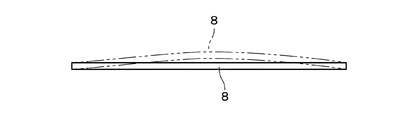
- FIG. 4 is a view showing a warped ceramic laminate.
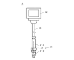
- FIG. 1 is a diagram showing a gas sensor 1 according to one embodiment of the present invention.
- the gas sensor 1 is used for measuring the concentration of a predetermined gas component contained in the gas to be measured.
- the gas sensor 1 is used for measuring the concentration of NOx or the like contained in exhaust gas from an automobile.
- the gas sensor 1 is attached to, for example, an exhaust gas pipe of an automobile.
- the gas sensor 1 includes a sensor body 11, an external connection unit 12, and a tube 13.
- the tube 13 covers a plurality of lead wires connecting the sensor main body 11 and the external connection portion 12.
- the external connection unit 12 includes a plurality of terminal electrodes (not shown) connected to a plurality of lead wires, respectively.
- the terminal electrode is electrically connected to an electrode of the sensor element 2 described below via a lead wire.
- the external connection unit 12 is connected to, for example, a control unit of an automobile. The control unit supplies a current to the sensor element 2 and receives a signal from the sensor element 2.
- the sensor main body 11 includes the sensor element 2, the main body cylindrical portion 111, and the protective cover 112.
- the sensor element 2 has a long plate shape and measures the concentration of a predetermined gas component from the gas to be measured.
- the structure of the sensor element 2 will be described later.
- the main body tubular portion 111 is a tubular member that houses the sensor element 2 therein.
- One end of the sensor element 2 (a lower end in FIG. 1, hereinafter referred to as a “tip”) is disposed outside the main body cylindrical portion 111, and the protective cover 112 is It surrounds the periphery of the tip of the sensor element 2.
- the protective cover 112 has a through-hole for allowing the gas to be measured to flow.
- FIG. 2 is a cross-sectional view showing the structure of the sensor element 2.
- X, Y, and Z directions that are orthogonal to each other are indicated by arrows.
- the sensor element 2 has a long plate shape
- the Y direction in FIG. 2 is the longitudinal direction of the sensor element 2
- the X direction is the width direction of the sensor element 2.
- the sensor element 2 is formed by stacking a plurality of layers (or sheets), and the Z direction in FIG. 2 is the stacking direction.
- FIG. 2 shows a cross section perpendicular to the width direction.
- the sensor element 2 includes the element main body 20 and the porous protection portion 5 covering a part of the element main body 20.
- the element body 20 includes a zirconia layer 3 and two alumina layers 4a and 4b.
- two alumina layer portions 4a and 4b are respectively provided on both surfaces (surfaces facing the laminating direction) of the zirconia layer portion 3.
- the zirconia layer portion 3 and the alumina layer portions 4a and 4b are mainly formed of ceramic, and the element body 20 is a ceramic laminate.
- the zirconia layer section 3 includes a first substrate layer 31, a second substrate layer 32, a third substrate layer 33, a first solid electrolyte layer 34, a spacer layer 35, and a second solid electrolyte layer 36.
- the first substrate layer 31, the second substrate layer 32, the third substrate layer 33, the first solid electrolyte layer 34, the spacer layer 35, and the second solid electrolyte layer 36 move from the (-Z) side toward the (+ Z) direction.
- the layers are stacked in this order.
- Each of the plurality of layers 31 to 36 included in the zirconia layer portion 3 is formed of a ceramic containing zirconia (ZrO 2 ) as a main component.
- the main component of each of the layers 31 to 36 means a component contained by 50% by mass or more based on the whole of the layers 31 to 36. The same applies hereinafter.
- Each of the layers 31 to 36 has a dense structure and is airtight.
- the zirconia layer 3 mainly composed of zirconia (and the layers 31 to 36) has oxygen ion conductivity.
- the zirconia layer 3 preferably contains zirconia in an amount of 65% by mass or more, and more preferably 80% by mass or more based on the entire zirconia layer 3. More preferably, it is included.
- the zirconia layer portion 3 is formed by, for example, performing predetermined processing and printing a pattern on ceramic green sheets corresponding to the respective layers 31 to 36, laminating these sheets, and firing and integrating them. It is produced by
- a space 351 formed by removing a part of the spacer layer 35 is provided at a position on the tip end side ((-Y) side), and the space 351 includes a plurality of spaces. Electrodes 371 to 375 are provided. The electrode 376 is also formed on the (+ Z) side surface of the second solid electrolyte layer 36. Around the electrode 376, a through-hole for releasing oxygen pumped from the gas to be measured to the outside is provided. A space 341 is provided between the third substrate layer 33 and the spacer layer 35 at a portion of the zirconia layer portion 3 away from the tip portion on the (+ Y) side. The space 341 is defined by the side surface of the first solid electrolyte layer 34.
- a porous ceramic layer 331 and an electrode 377 are provided between the third substrate layer 33 and the first solid electrolyte layer 34. At least some of the electrodes 371 to 377 are formed as porous cermet electrodes (for example, cermet electrodes of Pt and ZrO 2 ).
- the zirconia layer section 3 further includes a heater section 38.
- the heater section 38 is provided between the second substrate layer 32 and the third substrate layer 33.
- the heater section 38 is formed by covering the electric resistor with an insulator such as alumina. A current is supplied to the electric resistor from a connector electrode (not shown).
- the heater section 38 heats the zirconia layer section 3 to, for example, 600 ° C. or higher, so that the oxygen ion conductivity in the solid electrolyte layers 34 and 36 is increased.
- an electrochemical pump cell and an electrochemical sensor cell are realized by the electrodes 371 to 377 and the solid electrolyte layers 34 and 36.
- the gas to be measured is introduced into the space 351 from a gas inlet (not shown), and the NOx concentration of the gas to be measured is measured by the cooperation of the pump cell and the sensor cell.
- the measurement using the oxygen ion conductivity in the zirconia layer 3 is performed. Since the principle of measuring the NOx concentration in the sensor element 2 is well known, the description is omitted here.
- zirconia layer portion 3 includes a plurality of layers containing zirconia as a main component.
- the lower limit of the thickness of the zirconia layer portion 3 in the laminating direction is, for example, 400 ⁇ m, and preferably 500 ⁇ m.
- the upper limit of the thickness of the zirconia layer 3 is, for example, 1800 ⁇ m, and preferably 1600 ⁇ m.
- the alumina layer portion 4a is in contact with the (-Z) side surface of the first substrate layer 31, and typically covers the entire surface.
- the alumina layer portion 4b is in contact with the (+ Z) side surface of the second solid electrolyte layer 36, and typically covers the entire surface.
- Each of the two alumina layers 4a and 4b is formed of a ceramic mainly containing alumina (Al 2 O 3 ).
- the zirconia layer 3 is protected by the alumina layers 4a and 4b.
- each of the alumina layer portions 4a and 4b preferably contains 65% by mass or more of alumina with respect to the entirety of the alumina layer portions 4a and 4b. More preferably, the content is 80% by mass or more.
- the lower limit of the thickness of each of the alumina layers 4a and 4b in the laminating direction is, for example, 10 ⁇ m, preferably 20 ⁇ m, and more preferably 30 ⁇ m.
- the upper limit of the thickness of the alumina layers 4a and 4b is, for example, 700 ⁇ m, preferably 600 ⁇ m, and more preferably 500 ⁇ m.
- the thickness of the two alumina layers 4a and 4b is substantially the same, for example, when the thickness of one alumina layer is 80% or more and 120% or less of the thickness of the other alumina layer. is there.
- the thicknesses of the two alumina layer portions 4a and 4b may be different from the above ranges.
- the lower limit of the ratio (T1 / T2) of the thickness T1 of the zirconia layer 3 to the thickness T2 of each of the alumina layers 4a and 4b is, for example, 0.1, and preferably 0.2. , More preferably 0.4.
- the upper limit of the ratio is, for example, 25, preferably 24, and more preferably 23.
- the upper limit of the open porosity of the alumina layers 4a and 4b is, for example, 10%, and preferably 5%.
- the lower limit of the open porosity of the alumina layers 4a and 4b is, for example, 0.1%, and preferably 0.3%.
- the open porosity can be measured, for example, by the Archimedes method. Details of the material of the alumina layers 4a and 4b will be described later.
- the sensor element 2 includes the porous protection unit 5.
- the porous protection portion 5 covers the surface of the element body 20 at the tip end side (( ⁇ Y) side). More specifically, the tip side of the ( ⁇ Z) side face, the tip side of the (+ Z) side, the tip side of the ( ⁇ X) side, and the (+ X) side face of the element body 20. And the entire surface on the ( ⁇ Y) side is covered with the porous protective portion 5.
- the porous protection portion 5 is formed of, for example, a porous ceramic such as alumina, zirconia, spinel, cordierite, titania, or magnesia.
- the porous protection part 5 is formed of alumina. In this case, since both the alumina layer portions 4a and 4b and the porous protection portion 5 contain alumina, it is possible to improve the adhesion between them.
- the porous protection portion 5 protects a portion on the tip end side of the element body 20. If moisture or the like in the gas to be measured adheres to the zirconia layer 3, the zirconia layer 3 may be subjected to thermal shock due to local rapid cooling, and cracks may occur. is there. On the other hand, in the sensor element 2 provided with the porous protection portion 5, the moisture and the like in the gas to be measured are prevented from adhering to the zirconia layer portion 3, and the generation of cracks in the zirconia layer portion 3 is suppressed. Further, the porous protective portion 5 also prevents an oil component or the like contained in the gas to be measured from adhering to the electrode on the surface of the element body 20, and suppresses deterioration of the electrode.
- the above-described gas inlet in the zirconia layer portion 3 is covered by the porous protection portion 5.
- the porous protection portion 5 is formed of a porous body, the gas to be measured is protected by the porous protection portion. It is possible to reach the gas inlet through the part 5.
- the lower limit of the thickness of the porous protection portion 5 is, for example, 100 ⁇ m, and preferably 200 ⁇ m.
- the upper limit of the thickness of the porous protection portion 5 is, for example, 1000 ⁇ m, and preferably 900 ⁇ m.
- the lower limit of the open porosity of the porous protective portion 5 is, for example, 5%, and preferably 10%.
- the upper limit of the open porosity of the porous protection portion 5 is, for example, 85%, and preferably 80%.
- the alumina layer portion 4 contains alumina as a main component and further contains additional elements.
- the added element is an element other than Al (aluminum) and O (oxygen) constituting alumina, and is an element contained in any of transition metals, rare earths, alkali metals, and alkaline earth metals (however, Zr ( Zirconium), Y (yttrium), Mg (magnesium) and Ca (calcium).
- the alumina layer portion 4 may include two or more elements included in any of transition metals, rare earths, alkali metals, and alkaline earth metals.
- Preferred additional elements are Ti (titanium), Na (sodium), Sc (scandium), V (vanadium), Cr (chromium), Mn (manganese), Fe (iron), Ni (nickel), Cu (copper), Any of Zn (zinc), Sr (strontium), Nb (niobium), Mo (molybdenum), Ba (barium), La (lanthanum), Ce (cerium), Pr (praseodymium) and Yb (ytterbium) is there.
- a more preferred additive element is a Ti element.
- the alumina layer section 4 includes titania (TiO 2 ).
- the alumina layer portion 4 may be included in any of transition metals, rare earths, alkali metals, and alkaline earth metals in addition to the Ti element, which is an additive element, and may further include another element different from the Ti element. Examples of such other elements include Zr, Y, Mg, and Ca. In one example, these elements exist in the alumina layer portion 4 as oxides (zirconia, yttria, magnesia, and calcia) or composite oxides with Al and Ti. Further, the other element may be contained in a reaction layer 39 described later. When the alumina layer 4 contains Mg in addition to the Ti element, the mechanical strength (bending strength in this case) of the element body 20 can be improved.
- the alumina layer portion 4 contains alumina as a main component and further contains an additional element, thereby suppressing warpage in the element body 20, that is, warpage in the sensor element 2. it can. This prevents troubles in assembling the gas sensor 1.
- the alumina layer section 4 contains the additive element
- the vicinity of the interface between each alumina layer section 4 and the zirconia layer section 3 is shown in FIG.
- a layer 39 of a reaction phase containing the Zr element and the additional element hereinafter, referred to as “reaction layer 39”.
- reaction layer 39 is a part of the zirconia layer portion 3.
- the reaction layer 39 is a layer in contact with the alumina layer 4.
- the presence of the reaction layer 39 may contribute to the suppression of warpage.
- the coefficient of thermal expansion of the reaction layer 39 is considered to be a value between the coefficient of thermal expansion of the alumina layer 4 and the coefficient of thermal expansion of the zirconia layer 3 excluding the reaction layer 39.
- the reaction layer 39 Reduces the difference in thermal expansion between the alumina layer 4 and the zirconia layer 3.
- the thickness of the reaction layer 39 is sufficiently smaller than the thickness of the layers 31 and 36 with which the alumina layer portion 4 is in contact, and is preferably 5 to 100 ⁇ m. If the thickness of the reaction layer 39 is larger than 100 ⁇ m, the oxygen ion conductivity in the zirconia layer 3 may be reduced. If the reaction layer 39 is thinner than 5 ⁇ m, the warpage of the element body 20 may increase, or the zirconia layer 3 and the alumina layer 4 may peel off. The thickness of the reaction layer 39 is more preferably 10 to 50 ⁇ m.
- the side surface (the surface along the stacking direction) of the element body 20 is mirror-polished, and the polished surface is subjected to surface analysis with an energy dispersive X-ray spectrometer (EDS). Then, a region where the Zr element and the additive element coexist is specified as the reaction layer 39. Further, the thickness of the region is obtained as the thickness of the reaction layer 39.
- the portions of the zirconia layer portion 3 in contact with the alumina layer portion 4 except for the reaction layer 39 do not contain any additional element (Ti element in a preferred example). Includes a layer in which no additional elements are present.
- the reaction layer 39 containing the Zr element and the Ti element uniformly is generated.
- the Ti element is dissolved in the zirconia crystal structure in the zirconia layer portion 3 to form a reaction layer 39.
- titania crystals may be mixed.
- the reaction layer 39 may be a layer containing a Zr element and a Ti element.
- the reaction layer 39 preferably contains 0.05 to 5.0% by mass of the Ti element, more preferably 0.05 to 3.5% by mass. Thereby, the warpage of the element body 20 can be suppressed more reliably.
- the ratio of the Ti element in the reaction layer 39 is preferably 0.1% by mass or more. In order to improve the strength of the element body 20, the ratio of the Ti element in the reaction layer 39 is preferably 3.0% by mass or less.
- the ratio of the Ti element in the reaction layer 39 can be obtained, for example, by surface analysis in the EDS. Due to the diffusion of the Ti element contained in the alumina layer part 4 into the zirconia layer part 3 (reaction layer 39), the mass ratio of the Ti element is more localized in the alumina layer part 4 near the reaction layer 39 than in other parts. May be lower.
- a layer in which the mass ratio of the Ti element is lower than other portions may be provided in the vicinity of the interface with the reaction layer 39.
- the Zr element may diffuse into the alumina layer portion 4.
- the alumina layer portion 4 preferably contains the Ti element in an amount of 0.1% by mass or more in terms of oxide (typically as TiO 2 ). Thereby, the reaction layer 39 in which the Ti element is appropriately dispersed can be formed, and the warpage in the element body 20 can be more reliably suppressed.
- the alumina layer portion 4 preferably contains the Ti element in an amount of 0.5% by mass or more in terms of oxide, more preferably 1.0% by mass or more. More preferred. If the Ti element contained in the alumina layer portion 4 is excessively large, the amount of alumina for securing mechanical strength is reduced.
- the mass ratio of the Ti element in the alumina layer portion 4 is preferably 10% by mass or less in terms of oxide, and is preferably 9% by mass or less. More preferably, it is even more preferably 8% by mass or less.
- the porous protective portion 5 that covers a part of the element main body 20 (the tip in the above example) is omitted, and the alumina layer section containing the additive element causes the element main body 20 to be removed. Part may be covered.
- the alumina layer covering the entirety of the tip side of the ( ⁇ X) side, the tip side of the (+ X) side, and the entire surface of the ( ⁇ Y) side is provided.
- a portion is formed in addition to the alumina layer portions 4a and 4b. Since the alumina layer portion is also excellent in water resistance, it is possible to suppress the occurrence of cracks when moisture or the like in the gas to be measured adheres to the element body 20.
- the same number of unfired ceramic green sheets as the layers 31 to 36 included in the zirconia layer portion 3 are prepared. These ceramic green sheets are to be the layers 31 to 36 and are zirconia green sheets containing a zirconia raw material as a main component.
- the zirconia green sheet contains an organic binder, an organic solvent, and the like in addition to the zirconia raw material (the same applies to an alumina green sheet described later).
- a pattern of an electrode, an insulating layer, a resistance heating element and the like according to the design of the corresponding layers 31 to 36 is printed.
- Ceramic green sheets are intended to become the alumina layers 4a and 4b, and are alumina green sheets containing an alumina raw material as a main component and containing additional elements.
- the additive element is contained in the alumina green sheet as an oxide such as titania.
- a laminated body is formed by sequentially laminating one alumina green sheet, a plurality of zirconia green sheets corresponding to the layers 31 to 36, and one alumina green sheet while interposing an adhesive paste between the green sheets. can get.
- the adhesive paste includes, for example, zirconia powder, a binder, and an organic solvent.
- each element body before firing is taken out, and fired at a predetermined firing temperature (the highest temperature during firing, for example, 1300 to 1500 ° C.), whereby the element body 20 is obtained.
- a predetermined firing temperature the highest temperature during firing, for example, 1300 to 1500 ° C.
- an alumina sheet before firing may be formed by applying a paste containing alumina as a main component and containing an additional element to the surfaces of the zirconia green sheets on both surfaces of the zirconia layer portion 3.
- the element body 20 does not necessarily need to be formed by co-firing.
- the zirconia layer 3 and the alumina layers 4a and 4b may be stacked and fired again.
- the porous protective portion 5 is formed on a part of the surface of the element body 20.
- the porous protection portion 5 is formed by, for example, plasma spraying using a plasma gun.
- a plasma spraying for example, a sprayed material containing alumina powder is sprayed together with a carrier gas onto the surface of the element body 20 at the front end ((-Y) side). More specifically, the tip side of the ( ⁇ Z) side face, the tip side of the (+ Z) side, the tip side of the ( ⁇ X) side, and the (+ X) side face of the element body 20.
- the sprayed material is sprayed on the entire surface on the tip end side and on the ( ⁇ Y) side, thereby forming the porous protective portion 5.
- the sensor element 2 is completed.
- the firing shrinkage curve of the alumina green sheet to be the alumina layer portions 4a and 4b and the firing shrinkage curve of the zirconia green sheet to be the zirconia layer portion 3 be similar.
- the firing shrinkage curve indicates a change in the shrinkage rate (the ratio of the shrunken length to the initial length) of the green sheet as the temperature increases during firing.
- the temperature at which the shrinkage rate of the green sheet during firing becomes 2% or more is defined as the shrinkage start temperature.
- the difference (absolute value) between the shrinkage start temperature of the alumina green sheet and the shrinkage start temperature of the zirconia green sheet is approximated to some extent.
- the firing shrinkage curve (shrinkage rate at shrinkage initiation temperature and firing temperature) can be measured using a thermomechanical analyzer (TMA).
- the firing shrinkage curve of the alumina green sheet and the firing shrinkage curve of the zirconia green sheet are close to each other, the shrinkage of the alumina green sheet and the zirconia green sheet starts almost simultaneously when the temperature rises in co-firing, and the firing temperature (maximum temperature) ), The contraction amounts of both are almost the same. Therefore, it is possible to further suppress the warpage of the element body 20.
- the firing shrinkage curve of an alumina green sheet containing no Ti element does not approximate the firing shrinkage curve of a zirconia green sheet, but the firing shrinkage curve of an alumina green sheet containing a Ti element (for example, titania) as an additive element has a zirconia green sheet.
- the difference between the shrinkage start temperature of the alumina green sheet and the shrinkage start temperature of the zirconia green sheet is preferably 70 ° C or less, and more preferably 50 ° C or less. It is more preferable that the temperature is 30 ° C. or lower. Further, the difference between the shrinkage rate of the alumina green sheet and the shrinkage rate of the zirconia green sheet at the firing temperature does not greatly differ, but in order to more reliably suppress the warpage, the difference is 4% point or less. It is more preferably at most 3%, more preferably at most 2%.
- the element contained in the aid may diffuse into the zirconia layer 3 during co-firing.
- the diffusion of the element contained in the auxiliary into the zirconia layer 3 affects the characteristics of the element body 20 (for example, the oxygen ion conductivity in the zirconia layer 3). May decrease).
- an alumina green sheet to which an appropriate amount of an auxiliary agent containing Ti element is added so that the reaction layer 39 contains 0.05 to 5.0% by mass of Ti element.
- alumina powder, titania powder as an auxiliary agent, powder of other auxiliary agents, a plasticizer, and an organic solvent were weighed, and these materials were mixed for 10 hours using a pot mill. .
- a mixture serving as a raw material of the alumina green sheet was obtained.
- the mixing ratio of alumina (Al 2 O 3 ), titania (TiO 2 ) and other auxiliaries (SiO 2 , ZrO 2 , MgO, Y 2 O 3 ) in the mixture is as shown in “Composition” in Table 1. .
- a binder solution containing a polyvinyl butyral (PVB) resin and an organic solvent was added to the above mixture, and the mixture was further mixed for 10 hours. Thereafter, the viscosity was adjusted by a predetermined method, and an alumina green sheet was obtained by a tape forming method. The thickness of the alumina green sheet is 250 ⁇ m. Also, a zirconia green sheet containing a zirconia raw material was obtained by the same operation as the alumina green sheet. The thickness of the zirconia green sheet is 250 ⁇ m.
- PVB polyvinyl butyral
- the open porosity was measured by the Archimedes method on a single alumina layer 84 obtained by firing an alumina green sheet.
- “open porosity” of Table 2 “ ⁇ ” is given to the ceramic laminate 8 in which the open porosity of the alumina layer portion 84 is 0% or more and less than 4%, and the ceramic laminate 8 is 4% or more and less than 10%. 8 are marked with “ ⁇ ”, and the ceramic laminates 10% or more are marked with “x”.
- the open porosity of the alumina layer portion 84 becomes 10% or more (denseness is reduced).
- the open porosity was less than 10%, and a dense alumina layer portion 84 was obtained.
- the shrinkage onset temperature In the measurement of the shrinkage onset temperature, the shrinkage onset temperature when the alumina green sheets in Examples 1 to 8 and Comparative Examples 1 to 5 were baked alone was measured using a thermomechanical analyzer (TMA). The shrinkage start temperature was a temperature at which the shrinkage of the green sheet became 2% or more. In addition, the shrinkage start temperature when the zirconia green sheet was baked alone was also measured, and the difference between the shrinkage start temperature of the alumina green sheet and the shrinkage start temperature of the zirconia green sheet was determined.
- TMA thermomechanical analyzer
- the absolute value of the difference between the shrinkage start temperature of the alumina green sheet and the shrinkage start temperature of the zirconia green sheet (hereinafter, simply referred to as “difference in shrinkage start temperature”) is 30 ° C. or less.
- Certain ceramic laminates 8 are marked with “ ⁇ ”, and ceramic laminates 8 that are greater than 30 ° C. and 50 ° C. or less are marked with “ ⁇ ” and are greater than 50 ° C. and 70 ° C. or less.
- a certain ceramic laminated body 8 is marked with “ ⁇ ”, and a ceramic laminated body 8 having a temperature higher than 70 ° C. is marked with “x”.
- the difference in shrinkage start temperature was 50 ° C.
- the warped ceramic laminate 8 is indicated by a two-dot chain line.
- the ceramic laminated body 8 is placed on a horizontal installation surface with one alumina layer portion 84 being placed on the lower side, and a 3D shape measuring machine (VR-3000, manufactured by Keyence Corporation) is used. Then, the entire surface facing the upper side of the other alumina layer portion 84 was scanned.
- the installation surface is set as a reference surface in the average step mode, and a region of 80% or more in the longitudinal direction and a region of 30% or more in the width direction (transverse direction) on the surface of the alumina layer portion 84 is measured.
- a value obtained by subtracting the minimum height from the maximum height of the measurement surface was calculated as warpage.
- the warpage of the ceramic laminates 8 of Examples 1 to 8 was 300 ⁇ m or less, whereas the warpage of the ceramic laminates 8 of Comparative Examples 1 and 4 greatly exceeded 300 ⁇ m. If the warpage of the ceramic laminated body 8 exceeds 300 ⁇ m, when the ceramic laminated body 8 is the above-described element main body 20, there is a problem in assembling the gas sensor 1. In the ceramic laminates 8 of Examples 4 to 6, the warpage was less than 200 ⁇ m. It is considered that in the ceramic laminates 8 of Examples 4 to 6, the difference in the shrinkage start temperature became 30 ° C. or less due to the addition of MgO to the raw material of the alumina green sheet, and it is considered that the warpage was largely suppressed.
- the side surface (the surface along the laminating direction) of the ceramic laminate 8 is mirror-polished, and the vicinity of the interface between the zirconia layer portion 83 and the alumina layer portion 84 on the polished surface is measured by a scanning electron microscope (SEM). Was observed at a magnification of 1000 times. Further, a surface analysis of Zr and Ti is performed by an energy dispersive X-ray spectrometer (EDS), and a region where the Ti element exists (a region where the Zr element and the Ti element are mixed) in the zirconia layer portion 83 is used as a reaction layer. Identified.
- EDS energy dispersive X-ray spectrometer
- An electron probe microanalyzer can also be used for the analysis of Zr and Ti. As shown in Table 1, the presence of the reaction layer was confirmed in the ceramic laminates 8 of Examples 1 to 8, whereas the presence of the reaction layer was confirmed in the ceramic laminates 8 of Comparative Examples 1 and 4. Did not. Therefore, it is considered that the presence of the reaction layer contributes to the suppression of the warpage.
- the thickness of the region specified in the confirmation of the reaction layer was measured as the thickness of the reaction layer.
- the thickness of the reaction layer was in the range of 5 to 100 ⁇ m.
- the ratio of the Ti element in the reaction layer was obtained from the surface analysis by the EDS. From Examples 1 to 8, it can be said that if the ratio of the Ti element in the reaction layer is 0.05 to 3.5% by mass, the warpage can be more reliably suppressed. Also in the ceramic laminate 8 of Example 8 in which the ratio of the Ti element in the reaction layer is 3.5% by mass, the warpage is 240 ⁇ m, which is sufficiently small. Therefore, if the ratio of the Ti element is 5.0% by mass or less, it is considered that the warpage can be suppressed to 300 ⁇ m or less.
- the thickness of the reaction layer and the ratio of the Ti element in the reaction layer depend on the mass ratio of TiO 2 in the raw material of the alumina green sheet.
- the mass ratio of TiO 2 in the raw material of the alumina green sheet is excessively small, the thickness of the reaction layer and the ratio of the Ti element are significantly reduced, and in this case, the warpage increases, or It is considered that separation from the zirconia layer 83 occurs.
- the thickness of the reaction layer is 5 ⁇ m or more, or when the ratio of the Ti element in the reaction layer is 0.05 mass% or more, the occurrence of peeling and warpage can be suppressed more reliably. It is.
- the load that broke in the bending test was 200 N or more, while in Example 8, the load broke in the bending test.
- the load was less than 200N. Therefore, in order to ensure a certain level of mechanical strength in the ceramic laminate 8, the mass ratio of the Ti element in the alumina layer portion 84 is 10 mass% or less in terms of oxide, or the proportion of the Ti element in the reaction layer. Is preferably 3.0% by mass or less. Thereby, the Al 2 O 3 and ZrO 2 which bear the strength in the ceramic laminate 8 are prevented from being relatively reduced. Further, in the ceramic laminates 8 of Examples 4 to 6, the mechanical strength was further improved by adding MgO to the raw material of the alumina green sheet (the same applies to the water resistance to be described later).
- the amount of water droplets at which cracks occurred was 50 ⁇ L or more, whereas in Example 8, 5 ⁇ L of water droplets were generated. Cracks occurred due to water droplets.
- the reason for the decrease in the water resistance of the ceramic laminate 8 of the eighth embodiment is not clear, but in order to secure a certain degree of water resistance in the ceramic laminate 8, as in the case of the mechanical strength, the alumina layer 84 has It is considered preferable that the mass ratio of the Ti element is 10% by mass or less in terms of oxide, or the ratio of the Ti element in the reaction layer is 3.0% by mass or less.
- both of the two alumina layer portions 4a and 4b contain an additional element (for example, Ti element), but one of the alumina layer portions contains the additional element and the other alumina layer portion contains the additional element. Even when the portion does not contain an additive element, it is possible to suppress the warpage of the element body 20 to some extent.
- the zirconia layer 3 has a reaction layer 39 containing a Zr element and an additive element in the vicinity of the interface with the at least one alumina layer.
- the sensor element 2 may be used for a sensor other than the gas sensor 1.
- the ceramic laminate in which the warpage is suppressed by the added element may be used for applications other than the sensor element 2.
- the ceramic laminate can be used as a firing setter that requires high thermal shock resistance.
- the zirconia layer portion may include only one layer containing zirconia as a main component.
- each alumina layer portion may include a plurality of layers mainly composed of alumina.
- the zirconia layer portion includes one or more layers containing zirconia as a main component
- the alumina layer portion includes one or more layers containing alumina as a main component. I just need.
Landscapes
- Chemical & Material Sciences (AREA)
- Engineering & Computer Science (AREA)
- Ceramic Engineering (AREA)
- Health & Medical Sciences (AREA)
- Life Sciences & Earth Sciences (AREA)
- Materials Engineering (AREA)
- Structural Engineering (AREA)
- Organic Chemistry (AREA)
- General Physics & Mathematics (AREA)
- Analytical Chemistry (AREA)
- Pathology (AREA)
- Immunology (AREA)
- General Health & Medical Sciences (AREA)
- Biochemistry (AREA)
- Physics & Mathematics (AREA)
- Electrochemistry (AREA)
- Chemical Kinetics & Catalysis (AREA)
- Molecular Biology (AREA)
- Inorganic Chemistry (AREA)
- Manufacturing & Machinery (AREA)
- Composite Materials (AREA)
- Combustion & Propulsion (AREA)
- Food Science & Technology (AREA)
- Medicinal Chemistry (AREA)
- Measuring Oxygen Concentration In Cells (AREA)
- Laminated Bodies (AREA)
Abstract
センサ素子(2)は、ジルコニア層部(3)、および、ジルコニア層部(3)の両面にそれぞれ設けられた2つのアルミナ層部(4a,4b)を有するセラミック積層体(20)と、セラミック積層体(20)に設けられる複数の電極(371~377)とを備える。2つのアルミナ層部(4a,4b)のうち少なくとも1つのアルミナ層部が、Ti元素を含み、ジルコニア層部(3)が、当該少なくとも1つのアルミナ層部との界面近傍において、Zr元素およびTi元素を含む層を有し、当該層が、Ti元素を0.05~5.0質量%含む。これにより、センサ素子(2)のセラミック積層体(20)における反りを抑制することができる。
Description
本発明は、センサ素子に関する。
従来、ジルコニアを用いたセンサが利用されている。例えば、特許第5104744号公報では、アルミナシートに設けた充填用貫通穴内に、ジルコニア材料からなるジルコニア充填部を設け、当該ジルコニア充填部の両表面に一対の電極を設けたガスセンサ素子が開示されている。また、特許第5198832号公報では、積層型の検出素子を備えるガスセンサが開示されており、当該検出素子は、ジルコニアを主成分とする固体電解質層を有する板状のセンサ機能部と、センサ機能部の両面上に積層されるとともに、アルミナを主成分とする基層から構成される板状の第1部および第2部とを備える。当該ガスセンサでは、第1部の基層と第2部の基層とが同程度の厚みとされ、検出素子の少なくとも一部に、センサ機能部の固体電解質層を中心に積層方向に対称的な構造をなす対称構造部が設けられる。これにより、素子全体の反りが抑制される。
なお、特開平8-15213号公報では、内燃機関排気系に設けられるヒータ付き酸素センサにおいて、内燃機関排気管の水分不発生温度に相当する所定の負荷量に達することを条件に酸素センサのヒータに通電を行う手法が開示されている。当該手法により、排気管に存在する水滴がセンサ素子に接触することによる素子割れが防止される。
ところで、センサ素子の製造等において、ジルコニア層部の両面に2つのアルミナ層部を形成したセラミック積層体を作製する場合、セラミック積層体において大きな反りが生じてしまう。この場合、例えば、センサ素子を用いたセンサの組立等において支障が生じてしまう。
本発明は、センサ素子に向けられており、センサ素子のセラミック積層体における反りを抑制することを目的としている。
本発明に係る一のセンサ素子は、ジルコニア層部、および、前記ジルコニア層部の両面にそれぞれ設けられた2つのアルミナ層部を有するセラミック積層体と、前記セラミック積層体に設けられる複数の電極とを備え、前記2つのアルミナ層部のうち少なくとも1つのアルミナ層部が、Ti元素を含み、前記ジルコニア層部が、前記少なくとも1つのアルミナ層部との界面近傍において、Zr元素およびTi元素を含む層を有し、前記層が、Ti元素を0.05~5.0質量%含む。
本発明によれば、センサ素子のセラミック積層体における反りを抑制することができる。
本発明の一の好ましい形態では、前記層の厚さが、5~100μmである。
本発明の他の好ましい形態では、前記少なくとも1つのアルミナ層部が、遷移金属、希土類、アルカリ金属およびアルカリ土類金属のいずれかに含まれる他の元素をさらに含む。
本発明の他の好ましい形態では、前記2つのアルミナ層部の双方がTi元素を含む。
本発明の他の好ましい形態では、前記ジルコニア層部および前記2つのアルミナ層部が、共焼成により形成される。
本発明の他の好ましい形態では、センサ素子が、前記セラミック積層体の一部を覆う多孔質保護部をさらに備える。
上述の目的および他の目的、特徴、態様および利点は、添付した図面を参照して以下に行うこの発明の詳細な説明により明らかにされる。
図1は、本発明の一の実施の形態に係るガスセンサ1を示す図である。ガスセンサ1は、被測定ガスに含まれる所定のガス成分の濃度の測定に用いられる。一例では、ガスセンサ1は、自動車の排ガスに含まれるNOx等の濃度の測定に用いられる。被測定ガスが排ガスである場合、ガスセンサ1は、例えば自動車の排ガス管に取り付けられる。
ガスセンサ1は、センサ本体11と、外部接続部12と、チューブ13とを備える。チューブ13は、センサ本体11と外部接続部12とを接続する複数のリード線を覆う。外部接続部12は、複数のリード線にそれぞれ接続された複数の端子電極(図示省略)を備える。端子電極は、リード線を介して後述のセンサ素子2の電極と導通する。外部接続部12は、例えば自動車の制御ユニットに接続される。制御ユニットにより、センサ素子2に対して電流が供給されるとともに、センサ素子2からの信号が受信される。
センサ本体11は、センサ素子2と、本体筒状部111と、保護カバー112とを備える。センサ素子2は、長尺の板状であり、被測定ガスから所定のガス成分の濃度を測定する。センサ素子2の構造については後述する。本体筒状部111は、センサ素子2を内部に収容する筒状部材である。センサ素子2の一方の端部(図1中の下側の端部であり、以下、「先端部」という。)は、本体筒状部111から外側に配置されており、保護カバー112は、センサ素子2の先端部の周囲を囲む。保護カバー112には、被測定ガスを流通させるための貫通孔が形成される。
図2は、センサ素子2の構造を示す断面図である。図2では、互いに直交するX方向、Y方向およびZ方向を矢印で示している。既述のように、センサ素子2は長尺の板状であり、図2中のY方向がセンサ素子2の長手方向であり、X方向がセンサ素子2の幅方向である。また、後述するように、センサ素子2は、複数の層(またはシート)が積層されて形成されており、図2中のZ方向が積層方向である。図2では、幅方向に垂直な断面を示している。
センサ素子2は、素子本体20と、素子本体20の一部を覆う多孔質保護部5とを備える。素子本体20は、ジルコニア層部3と、2つのアルミナ層部4a,4bとを備える。素子本体20では、ジルコニア層部3の両面(積層方向を向く面)に2つのアルミナ層部4a,4bがそれぞれ設けられる。後述するように、ジルコニア層部3およびアルミナ層部4a,4bは、主としてセラミックにより形成されており、素子本体20は、セラミック積層体である。
ジルコニア層部3は、第1基板層31と、第2基板層32と、第3基板層33と、第1固体電解質層34と、スペーサ層35と、第2固体電解質層36とを備える。第1基板層31、第2基板層32、第3基板層33、第1固体電解質層34、スペーサ層35および第2固体電解質層36は、(-Z)側から(+Z)方向に向かってこの順序で積層される。
ジルコニア層部3に含まれる複数の層31~36は、いずれもジルコニア(ZrO2)を主成分とするセラミックにより形成される。ここで、各層31~36の主成分は、当該層31~36の全体に対して50質量%以上含まれる成分を意味する。以下同様である。各層31~36は緻密な構造を有し、気密性を有する。ジルコニアを主成分とするジルコニア層部3(および各層31~36)は、酸素イオン伝導性を有する。ジルコニア層部3において、酸素イオン伝導性をより確実に発揮させるという観点では、ジルコニア層部3は、ジルコニア層部3の全体に対してジルコニアを65質量%以上含むことが好ましく、80質量%以上含むことがより好ましい。後述するように、ジルコニア層部3は、例えば、各層31~36に対応するセラミックグリーンシートに所定の加工およびパターンの印刷等を行い、これらのシートを積層した後、焼成して一体化させることにより作製される。
ジルコニア層部3において、先端部側((-Y)側)の部位には、スペーサ層35の一部を除去して形成された空間351が設けられており、当該空間351には、複数の電極371~375が設けられる。また、第2固体電解質層36の(+Z)側の面にも電極376が形成される。電極376の周りには、被測定ガスからポンピングした酸素を外部に放出するための貫通孔を設けてある。ジルコニア層部3における、先端部から(+Y)側に離れた部位では、第3基板層33とスペーサ層35との間に空間341が設けられる。空間341は、第1固体電解質層34の側面で区画される。空間341の近傍において、第3基板層33と第1固体電解質層34との間には、多孔質セラミック層331や電極377が設けられる。これらの電極371~377のうち、少なくとも一部の電極は、多孔質サーメット電極(例えば、PtとZrO2とのサーメット電極)として形成される。
ジルコニア層部3は、ヒータ部38をさらに備える。ヒータ部38は、第2基板層32と第3基板層33との間に設けられる。ヒータ部38は、電気抵抗体をアルミナ等の絶縁体で覆うことにより形成される。電気抵抗体には、図示省略のコネクタ電極から電流が供給される。ヒータ部38がジルコニア層部3を、例えば、600℃以上に加熱することにより、固体電解質層34,36における酸素イオン伝導性が高められる。
ジルコニア層部3では、電極371~377および固体電解質層34,36等により、電気化学的ポンプセルや電気化学的センサセルが実現される。上記空間351には、図示省略のガス導入口から被測定ガスが導入され、ポンプセルおよびセンサセルが協働することにより、被測定ガスのNOx濃度が測定される。以上のように、センサ素子2では、ジルコニア層部3における酸素イオン伝導性を利用した測定が行われる。なお、センサ素子2におけるNOx濃度の測定原理については周知であるため、ここでは説明を省略する。
ジルコニア層部3における上記層31~36の個数は、センサ素子2の設計に応じて適宜変更されてよい。典型的には、ジルコニア層部3は、ジルコニアを主成分とする複数の層を含む。素子本体20の製造を容易に行うという観点では、積層方向におけるジルコニア層部3の厚さの下限値は、例えば400μmであり、好ましくは500μmである。素子本体20の小型化を図るという観点では、ジルコニア層部3の厚さの上限値は、例えば1800μmであり、好ましくは1600μmである。
アルミナ層部4aは、第1基板層31の(-Z)側の面に接し、典型的には、当該面の全体を覆う。アルミナ層部4bは、第2固体電解質層36の(+Z)側の面に接し、典型的には、当該面の全体を覆う。2つのアルミナ層部4a,4bは、いずれもアルミナ(Al2O3)を主成分とするセラミックにより形成される。アルミナ層部4a,4bによりジルコニア層部3が保護される。アルミナ層部4a,4bにおいて、ある程度の強度を確保するという観点では、各アルミナ層部4a,4bは、当該アルミナ層部4a,4bの全体に対してアルミナを65質量%以上含むことが好ましく、80質量%以上含むことがより好ましい。
素子本体20の製造を容易に行うという観点では、積層方向における各アルミナ層部4a,4bの厚さの下限値は、例えば10μmであり、好ましくは20μmであり、より好ましくは30μmである。素子本体20の小型化を図るという観点では、アルミナ層部4a,4bの厚さの上限値は、例えば700μmであり、好ましくは600μmであり、より好ましくは500μmである。好ましくは、2つのアルミナ層部4a,4bの厚さは、ほぼ同じであり、例えば、一方のアルミナ層部の厚さが、他方のアルミナ層部の厚さの80%以上かつ120%以下である。素子本体20の設計によっては、2つのアルミナ層部4a,4bの厚さが、上記範囲を超えて異なっていてもよい。
ジルコニア層部3の厚さT1と、各アルミナ層部4a,4bの厚さT2との比の値(T1/T2)の下限値は、例えば0.1であり、好ましくは0.2であり、より好ましくは0.4である。上記比の値の上限値は、例えば25であり、好ましくは24であり、より好ましくは23である。アルミナ層部4a,4bにおいて、ある程度の強度を確保するという観点では、アルミナ層部4a,4bの開気孔率の上限値は、例えば10%であり、好ましくは5%である。アルミナ層部4a,4bの開気孔率の下限値は、例えば0.1%であり、好ましくは0.3%である。開気孔率は、例えばアルキメデス法により測定可能である。アルミナ層部4a,4bの材料の詳細については後述する。
既述のように、センサ素子2は、多孔質保護部5を備える。多孔質保護部5は、素子本体20における先端部側((-Y)側)の部位の表面を覆う。具体的には、素子本体20の(-Z)側の面の先端部側、(+Z)側の面の先端部側、(-X)側の面の先端部側、(+X)側の面の先端部側、および、(-Y)側の面の全体が、多孔質保護部5により覆われる。多孔質保護部5は、例えば、アルミナ、ジルコニア、スピネル、コージェライト、チタニアまたはマグネシア等の多孔質セラミックにより形成される。本実施の形態では、多孔質保護部5がアルミナにより形成される。この場合、アルミナ層部4a,4bと多孔質保護部5とが共にアルミナを含むことにより、両者間の密着力を向上することが可能となる。
多孔質保護部5は、素子本体20における先端部側の部位を保護する。仮に、被測定ガス中の水分等がジルコニア層部3に付着した場合、付着部分が局所的に急激に冷却されることにより、ジルコニア層部3が熱衝撃を受け、クラックが発生する可能性がある。一方、多孔質保護部5が設けられるセンサ素子2では、被測定ガス中の水分等がジルコニア層部3に付着することが防止され、ジルコニア層部3におけるクラックの発生が抑制される。また、多孔質保護部5により、被測定ガスに含まれるオイル成分等が、素子本体20の表面上の電極に付着することも防止され、当該電極の劣化が抑制される。なお、センサ素子2では、ジルコニア層部3における既述のガス導入口が多孔質保護部5により覆われるが、多孔質保護部5が多孔質体により形成されため、被測定ガスは多孔質保護部5を通過してガス導入口に到達可能である。
素子本体20を適切に保護するという観点では、多孔質保護部5の厚さの下限値は、例えば100μmであり、好ましくは200μmである。センサ素子2の小型化を図るという観点では、多孔質保護部5の厚さの上限値は、例えば1000μmであり、好ましくは900μmである。被測定ガスをジルコニア層部3のガス導入口に適切に導くという観点では、多孔質保護部5の開気孔率の下限値は、例えば5%であり、好ましくは10%である。多孔質保護部5において、ある程度の強度を確保するという観点では、多孔質保護部5の開気孔率の上限値は、例えば85%であり、好ましくは80%である。
次に、アルミナ層部4a,4bの材料の詳細について説明する。以下の説明では、2つのアルミナ層部4a,4bを区別しない場合に、アルミナ層部4a,4bを「アルミナ層部4」と総称する。アルミナ層部4は、アルミナを主成分とするとともに、添加元素をさらに含む。ここで、添加元素は、アルミナを構成するAl(アルミニウム)およびO(酸素)以外の元素であり、遷移金属、希土類、アルカリ金属およびアルカリ土類金属のいずれかに含まれる元素(ただし、Zr(ジルコニウム)、Y(イットリウム)、Mg(マグネシウム)およびCa(カルシウム)を除く。)である。アルミナ層部4が、遷移金属、希土類、アルカリ金属およびアルカリ土類金属のいずれかに含まれる2種類以上の元素を含んでもよい。
好ましい添加元素は、Ti(チタン)、Na(ナトリウム)、Sc(スカンジウム)、V(バナジウム)、Cr(クロム)、Mn(マンガン)、Fe(鉄)、Ni(ニッケル)、Cu(銅)、Zn(亜鉛)、Sr(ストロンチウム)、Nb(ニオブ)、Mo(モリブデン)、Ba(バリウム)、La(ランタン)、Ce(セリウム)、Pr(プラセオジム)およびYb(イッテルビウム)のいずれかの元素である。
より好ましい添加元素は、Ti元素である。一例では、アルミナ層部4は、チタニア(TiO2)を含む。アルミナ層部4は、添加元素であるTi元素に加えて、遷移金属、希土類、アルカリ金属およびアルカリ土類金属のいずれかに含まれるとともに、Ti元素とは異なる他の元素をさらに含んでよい。当該他の元素として、Zr、Y、MgおよびCaを例示することができる。一例では、これらの元素は、アルミナ層部4において、酸化物(ジルコニア、イットリア、マグネシアおよびカルシア)またはAlやTiとの複合酸化物として存在する。また、後述の反応層39に当該他の元素が含まれてもよい。アルミナ層部4が、Ti元素に加えてMgを含む場合には、素子本体20の機械的強度(ここでは、曲げ強度)を向上することが可能となる。
セラミック積層体である素子本体20では、アルミナ層部4が、アルミナを主成分とするとともに、添加元素をさらに含むことにより、素子本体20における反り、すなわち、センサ素子2における反りを抑制することができる。これにより、ガスセンサ1の組立に支障が生じることが防止される。素子本体20において反りが抑制される理由は必ずしも明確ではないが、アルミナ層部4が添加元素を含む素子本体20では、各アルミナ層部4とジルコニア層部3との界面近傍において、図3に示すように、Zr元素と添加元素とを含む反応相の層39(以下、「反応層39」という。)が生成される。ここでは、反応層39は、ジルコニア層部3の一部であるものとする。反応層39は、アルミナ層部4と接する層である。素子本体20では、反応層39の存在が、反りの抑制に寄与している可能性がある。反応層39の熱膨張係数は、アルミナ層部4の熱膨張係数とジルコニア層部3の反応層39を除く部分の熱膨張係数との間の値であると考えられ、この場合、反応層39は、アルミナ層部4とジルコニア層部3との熱膨張差を緩和する。
反応層39の厚さは、アルミナ層部4が接する層31,36の厚さよりも十分に小さく、好ましくは5~100μmである。反応層39が100μmよりも厚くなると、ジルコニア層部3における酸素イオン伝導性が低下する可能性がある。反応層39が5μmよりも薄くなると、素子本体20における反りが大きくなる、または、ジルコニア層部3とアルミナ層部4とが剥離する可能性がある。反応層39の厚さは、より好ましくは10~50μmである。反応層39の特定では、例えば、素子本体20の側面(積層方向に沿う面)が鏡面研磨され、研磨面に対してエネルギー分散形X線分光器(EDS)における面分析が行われる。そして、Zr元素および添加元素が混在する領域が、反応層39として特定される。また、当該領域の厚さが、反応層39の厚さとして取得される。原則として、ジルコニア層部3のアルミナ層部4と接する層31,36において反応層39を除く部分は、添加元素(好ましい例では、Ti元素)を含まない、すなわち、当該層31,36は、添加元素が不存在である層を含む。
添加元素が、Ti元素である例では、Zr元素とTi元素とを一様に含む反応層39が生成される。一例では、ジルコニア層部3におけるジルコニアの結晶構造にTi元素が固溶して反応層39が形成される。反応層39では、チタニアの結晶が混在していてもよい。反応層39は、Zr元素およびTi元素を含む層であればよい。反応層39は、Ti元素を0.05~5.0質量%含むことが好ましく、0.05~3.5質量%含むことがより好ましい。これにより、素子本体20における反りをより確実に抑制することができる。Ti元素が適切に分散した反応層39を形成して、反りをさらに抑制するには、反応層39におけるTi元素の割合は、0.1質量%以上であることが好ましい。また、素子本体20の強度を向上するには、反応層39におけるTi元素の割合は、3.0質量%以下であることが好ましい。反応層39におけるTi元素の割合は、例えば、上記EDSにおける面分析により取得することが可能である。アルミナ層部4に含まれるTi元素のジルコニア層部3(反応層39)への拡散により、アルミナ層部4おいて反応層39の近傍では、Ti元素の質量割合が、他の部位よりも局所的に低くなる場合がある。すなわち、アルミナ層部4では、Ti元素の質量割合が他の部位よりも低い層が、反応層39との界面近傍に設けられる場合がある。反応層39の生成において、Zr元素が、アルミナ層部4に拡散してもよい。
添加元素が、Ti元素である場合、アルミナ層部4は、Ti元素を酸化物換算で(典型的には、TiO2として)0.1質量%以上含むことが好ましい。これにより、Ti元素が適切に分散した反応層39を形成することができ、素子本体20における反りをより確実に抑制することができる。Ti元素がより均等に分散した反応層39を形成するには、アルミナ層部4が、Ti元素を酸化物換算で0.5質量%以上含むことが好ましく、1.0質量%以上含むことがより好ましい。また、アルミナ層部4に含まれるTi元素が過度に多い場合には、機械的強度を確保するためのアルミナの量が少なくなってしまう。したがって、素子本体20における、ある程度の機械的強度を確保するには、アルミナ層部4におけるTi元素の質量割合が、酸化物換算で10質量%以下であることが好ましく、9質量%以下であることがより好ましく、8質量%以下であることがより一層好ましい。
なお、センサ素子2の設計によっては、素子本体20の一部(上記の例では、先端部)を覆う多孔質保護部5が省略され、添加元素を含むアルミナ層部により、素子本体20の当該一部が覆われてもよい。この場合、図2の素子本体20では、(-X)側の面の先端部側、(+X)側の面の先端部側、および、(-Y)側の面の全体をそれぞれ覆うアルミナ層部が、アルミナ層部4a,4bに加えて形成される。アルミナ層部も耐被水性に優れるため、被測定ガス中の水分等が素子本体20に付着した場合に、クラックの発生を抑制することができる。
センサ素子2の製造では、まず、ジルコニア層部3に含まれる層31~36と同数の未焼成のセラミックグリーンシートが準備される。これらのセラミックグリーンシートは、上記層31~36となる予定のものであり、ジルコニア原料を主成分とするジルコニアグリーンシートである。ジルコニアグリーンシートは、ジルコニア原料以外に、有機バインダ、有機溶剤等を含む(後述のアルミナグリーンシートにおいて同様)。各ジルコニアグリーンシートには、対応する層31~36の設計に従った電極、絶縁層、抵抗発熱体等のパターンが印刷される。
また、2つの未焼成のセラミックグリーンシートが準備される。これらのセラミックグリーンシートは、アルミナ層部4a,4bとなる予定のものであり、アルミナ原料を主成分とするとともに添加元素を含むアルミナグリーンシートである。添加元素は、例えばチタニア等の酸化物としてアルミナグリーンシートに含まれる。続いて、接着ペーストをグリーンシート間に介在させつつ、1つのアルミナグリーンシート、上記層31~36に対応する複数のジルコニアグリーンシート、および、1つのアルミナグリーンシートを順に積層することにより積層体が得られる。接着ペーストは、例えば、ジルコニアの粉末、バインダおよび有機溶剤を含む。
典型的には、当該積層体では、焼成前の状態である複数の素子本体が配列される。当該積層体を切断することにより、焼成前の各素子本体を取り出し、所定の焼成温度(焼成時の最高温度であり、例えば、1300~1500℃)で焼成することにより、素子本体20が得られる。このようにして、素子本体20におけるジルコニア層部3および2つのアルミナ層部4a,4bが、共焼成により一体的に形成される。
なお、アルミナを主成分とするとともに添加元素を含むペーストを、ジルコニア層部3の両面となるジルコニアグリーンシートの面に塗布することにより、焼成前のアルミナのシートが形成されてもよい。また、素子本体20は、必ずしも共焼成により形成される必要はなく、例えば、ジルコニア層部3およびアルミナ層部4a,4bを焼成により個別に作製した後、接着ペーストを介してジルコニア層部3およびアルミナ層部4a,4bを積層し、再度焼成が行われてもよい。
焼成体である素子本体20が得られると、素子本体20の表面の一部に多孔質保護部5が形成される。多孔質保護部5は、例えば、プラズマガンを用いたプラズマ溶射により形成される。プラズマ溶射では、例えば、アルミナ粉末を含む溶射材料がキャリアガスと共に、素子本体20における先端部側((-Y)側)の部位の表面に吹き付けられる。具体的には、素子本体20の(-Z)側の面の先端部側、(+Z)側の面の先端部側、(-X)側の面の先端部側、(+X)側の面の先端部側、および、(-Y)側の面の全体に溶射材料が吹き付けられ、多孔質保護部5が形成される。これにより、センサ素子2が完成する。
ところで、共焼成により素子本体20を作製する場合、アルミナ層部4a,4bとなるアルミナグリーンシートの焼成収縮曲線と、ジルコニア層部3となるジルコニアグリーンシートの焼成収縮曲線とが近似することが好ましい。ここで、焼成収縮曲線は、焼成時の温度上昇に伴うグリーンシートの収縮率(収縮した長さの、初期長さに対する比率)の変化を示す。焼成途上のグリーンシートの収縮率が2%以上となる際の温度を収縮開始温度として、例えば、アルミナグリーンシートの収縮開始温度とジルコニアグリーンシートの収縮開始温度との差(絶対値)がある程度近似し、かつ、実際の焼成温度におけるアルミナグリーンシートの収縮率とジルコニアグリーンシートの収縮率との差(絶対値)がある程度近似する場合に、2つの焼成収縮曲線が近似しているといえる。焼成収縮曲線(収縮開始温度および焼成温度における収縮率)は、熱機械分析装置(TMA)を用いて測定可能である。
アルミナグリーンシートの焼成収縮曲線と、ジルコニアグリーンシートの焼成収縮曲線とが近似する場合、共焼成における昇温時に、アルミナグリーンシートとジルコニアグリーンシートとがほぼ同時に収縮を開始し、焼成温度(最高温度)に到達した際においても、両者の収縮量はほぼ同じである。したがって、素子本体20における反りをさらに抑制することが可能となる。例えば、Ti元素を含まないアルミナグリーンシートの焼成収縮曲線は、ジルコニアグリーンシートの焼成収縮曲線と近似しないが、Ti元素(例えばチタニア)を添加元素として含むアルミナグリーンシートでは、焼成収縮曲線がジルコニアグリーンシートの焼成収縮曲線と近似する。素子本体20における反りをより確実に抑制するには、アルミナグリーンシートの収縮開始温度とジルコニアグリーンシートの収縮開始温度との差は、70℃以下であることが好ましく、50℃以下であることがより好ましく、30℃以下であることがより一層好ましい。また、焼成温度におけるアルミナグリーンシートの収縮率とジルコニアグリーンシートの収縮率との差は、大きく相違することはないが、反りをより確実に抑制するには、当該差は4%ポイント以下であることが好ましく、3%ポイント以下であることがより好ましく、2%ポイント以下であることがより一層好ましい。
上記のように助剤(添加剤)によりアルミナグリーンシートの焼成収縮曲線を調整する場合、助剤に含まれる元素が共焼成においてジルコニア層部3に拡散することがある。この場合に、助剤の種類や量によっては、助剤に含まれる元素のジルコニア層部3への拡散により、素子本体20の特性に影響が生じる(例えば、ジルコニア層部3における酸素イオン伝導性が低下する)可能性がある。これに対し、焼成体である素子本体20において、反応層39がTi元素を0.05~5.0質量%含むように、Ti元素を含む助剤を適切な量だけ添加したアルミナグリーンシートを利用する場合には、素子本体20の特性に影響が生じることを抑制しつつ、共焼成における素子本体20の反りを抑制することが可能となる。
<実施例>
(セラミック積層体の作製)
次に、セラミック積層体の実施例について述べる。ここでは、図4に示すように、ジルコニア層部83が4個の層831を含み、ジルコニア層部83の両面に2つのアルミナ層部84をそれぞれ形成したセラミック積層体8を作製した。
(セラミック積層体の作製)
次に、セラミック積層体の実施例について述べる。ここでは、図4に示すように、ジルコニア層部83が4個の層831を含み、ジルコニア層部83の両面に2つのアルミナ層部84をそれぞれ形成したセラミック積層体8を作製した。
セラミック積層体8の作製では、まず、アルミナの粉末、助剤であるチタニアの粉末、他の助剤の粉末、可塑剤および有機溶剤を秤量し、これらの材料をポットミルを用いて10時間混合した。これにより、アルミナグリーンシートの原料となる混合物を得た。当該混合物におけるアルミナ(Al2O3)、チタニア(TiO2)および他の助剤(SiO2、ZrO2、MgO、Y2O3)の混合比は表1の「組成」に示す通りである。

また、ポリビニルブチラール(PVB)樹脂および有機溶剤を含むバインダ溶液を、上記の混合物に追加し、さらに10時間混合した。その後、所定の手法で粘度調整を行い、テープ成形法によりアルミナグリーンシートを得た。アルミナグリーンシートの厚さは、250μmである。また、ジルコニア原料を含むジルコニアグリーンシートを、アルミナグリーンシートと同様の作業により得た。ジルコニアグリーンシートの厚さは、250μmである。
続いて、ジルコニアの粉末、バインダおよび有機溶剤を含む接着ペーストを、スクリーン印刷によりグリーンシートに塗布した。そして、接着ペーストをグリーンシート間に介在させつつ、1個のアルミナグリーンシート、4個のジルコニアグリーンシート、および、1個のアルミナグリーンシートを順に積層することにより、積層体を形成した。積層体の厚さは、1.5mmであった。なお、電極等のパターンの印刷は省略した。その後、当該積層体を(85mm×5mm)の大きさに切断し、1400℃で焼成した。これにより、実施例1~8のセラミック積層体8を得た。また、比較例1~5のセラミック積層体8も、同様の作業により作製した。表1のように、比較例1~5のセラミック積層体8では、アルミナグリーンシートが、添加元素の原料であるチタニアを含んでいない。
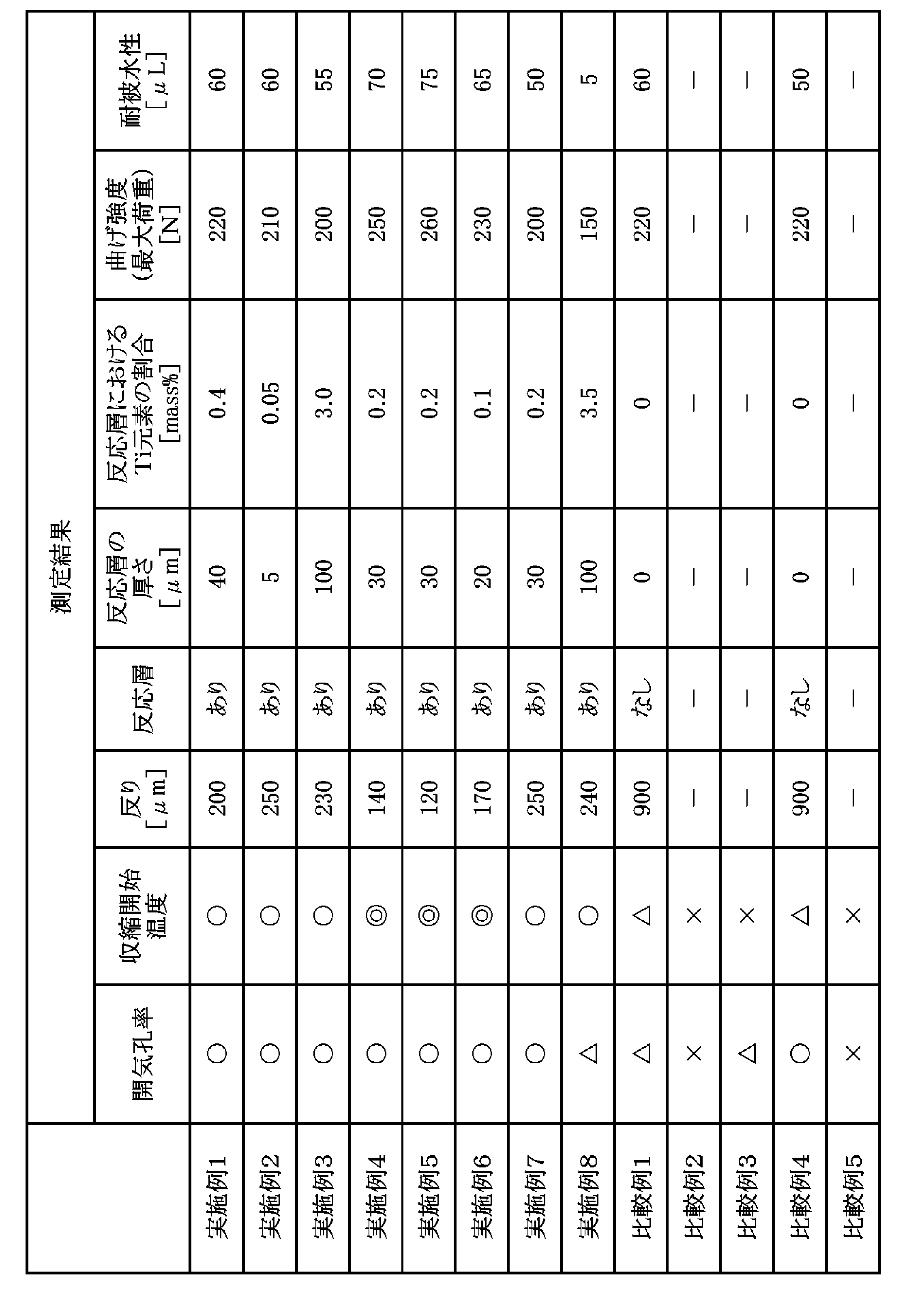
次に、実施例1~8、並びに、比較例1~5のセラミック積層体8に対して各種測定を行った。表2では、測定結果を示している。
(開気孔率の測定)
開気孔率の測定は、アルミナグリーンシートを焼成して得た、単体のアルミナ層部84に対して、アルキメデス法により行った。表2の「開気孔率」では、アルミナ層部84の開気孔率が0%以上4%未満であるセラミック積層体8に「〇」を付し、4%以上10%未満であるセラミック積層体8に「△」を付し、10%以上であるセラミック積層体8に「×」を付している。助剤としてSiO2およびY2O3をそれぞれ含む比較例2および5のセラミック積層体8では、アルミナ層部84の開気孔率が10%以上となる(緻密性が低下する)のに対し、実施例1~8、並びに、比較例1、3および4のセラミック積層体8では、開気孔率が10%未満となり、緻密なアルミナ層部84が得られた。
開気孔率の測定は、アルミナグリーンシートを焼成して得た、単体のアルミナ層部84に対して、アルキメデス法により行った。表2の「開気孔率」では、アルミナ層部84の開気孔率が0%以上4%未満であるセラミック積層体8に「〇」を付し、4%以上10%未満であるセラミック積層体8に「△」を付し、10%以上であるセラミック積層体8に「×」を付している。助剤としてSiO2およびY2O3をそれぞれ含む比較例2および5のセラミック積層体8では、アルミナ層部84の開気孔率が10%以上となる(緻密性が低下する)のに対し、実施例1~8、並びに、比較例1、3および4のセラミック積層体8では、開気孔率が10%未満となり、緻密なアルミナ層部84が得られた。
(収縮開始温度の測定)
収縮開始温度の測定では、実施例1~8、並びに、比較例1~5におけるアルミナグリーンシートを単体で焼成する際の収縮開始温度を、熱機械分析装置(TMA)を用いて測定した。収縮開始温度は、グリーンシートの収縮率が2%以上となる際の温度とした。また、ジルコニアグリーンシートを単体で焼成する際の収縮開始温度も測定し、アルミナグリーンシートの収縮開始温度とジルコニアグリーンシートの収縮開始温度との差を求めた。表2の「収縮開始温度」では、アルミナグリーンシートの収縮開始温度とジルコニアグリーンシートの収縮開始温度との差の絶対値(以下、単に「収縮開始温度の差」という。)が30℃以下であるセラミック積層体8に「◎」を付し、30℃よりも大きく、かつ、50℃以下であるセラミック積層体8に「〇」を付し、50℃よりも大きく、かつ、70℃以下であるセラミック積層体8に「△」を付し、70℃よりも大きいセラミック積層体8に「×」を付している。実施例1~8では、収縮開始温度の差が50℃以下であるのに対し、比較例1~5では、収縮開始温度の差が50℃よりも大きくなった。比較例2、3および5では、収縮開始温度の差が70℃よりも大きくなり、セラミック積層体8において、アルミナ層部84とジルコニア層部83との剥離が生じた。したがって、比較例2、3および5については、表2における他の測定を行わなかった。
収縮開始温度の測定では、実施例1~8、並びに、比較例1~5におけるアルミナグリーンシートを単体で焼成する際の収縮開始温度を、熱機械分析装置(TMA)を用いて測定した。収縮開始温度は、グリーンシートの収縮率が2%以上となる際の温度とした。また、ジルコニアグリーンシートを単体で焼成する際の収縮開始温度も測定し、アルミナグリーンシートの収縮開始温度とジルコニアグリーンシートの収縮開始温度との差を求めた。表2の「収縮開始温度」では、アルミナグリーンシートの収縮開始温度とジルコニアグリーンシートの収縮開始温度との差の絶対値(以下、単に「収縮開始温度の差」という。)が30℃以下であるセラミック積層体8に「◎」を付し、30℃よりも大きく、かつ、50℃以下であるセラミック積層体8に「〇」を付し、50℃よりも大きく、かつ、70℃以下であるセラミック積層体8に「△」を付し、70℃よりも大きいセラミック積層体8に「×」を付している。実施例1~8では、収縮開始温度の差が50℃以下であるのに対し、比較例1~5では、収縮開始温度の差が50℃よりも大きくなった。比較例2、3および5では、収縮開始温度の差が70℃よりも大きくなり、セラミック積層体8において、アルミナ層部84とジルコニア層部83との剥離が生じた。したがって、比較例2、3および5については、表2における他の測定を行わなかった。
(反りの測定)
図5では、反りが生じたセラミック積層体8を二点鎖線で示している。反りの測定では、一方のアルミナ層部84を下側に配置した状態で、セラミック積層体8を水平な設置面上に載置し、3D形状測定機(キーエンス社製、VR-3000)を用いて、他方のアルミナ層部84の上方を向く面の全体をスキャンした。平均段差モードで設置面を基準面として設定し、アルミナ層部84の上記面において長手方向の80%以上の範囲、および、幅方向(短手方向)の30%以上の範囲の領域を測定面として設定した。そして、測定面の最大高さから最小高さを引いて得た値を、反りとして算出した。
図5では、反りが生じたセラミック積層体8を二点鎖線で示している。反りの測定では、一方のアルミナ層部84を下側に配置した状態で、セラミック積層体8を水平な設置面上に載置し、3D形状測定機(キーエンス社製、VR-3000)を用いて、他方のアルミナ層部84の上方を向く面の全体をスキャンした。平均段差モードで設置面を基準面として設定し、アルミナ層部84の上記面において長手方向の80%以上の範囲、および、幅方向(短手方向)の30%以上の範囲の領域を測定面として設定した。そして、測定面の最大高さから最小高さを引いて得た値を、反りとして算出した。
表2に示すように、実施例1~8のセラミック積層体8では、反りが300μm以下であるのに対し、比較例1および4のセラミック積層体8では、反りが300μmを大幅に超えた。セラミック積層体8の反りが300μmを超えると、セラミック積層体8が上記素子本体20である場合に、ガスセンサ1の組立に支障が生じる。また、実施例4~6のセラミック積層体8では、反りが200μm未満となった。実施例4~6のセラミック積層体8では、アルミナグリーンシートの原料に対するMgOの添加により収縮開始温度の差が30℃以下となり、大幅に反りが抑制されたと考えられる。
(反応層の確認および反応層の各種測定)
反応層の確認では、セラミック積層体8の側面(積層方向に沿う面)を鏡面研磨した後、走査電子顕微鏡(SEM)装置で、研磨面におけるジルコニア層部83とアルミナ層部84との界面近傍を倍率1000倍で観察した。また、エネルギー分散形X線分光器(EDS)にて、ZrおよびTiの面分析を行い、ジルコニア層部83においてTi元素の存在する領域(Zr元素およびTi元素が混在する領域)を反応層として特定した。ZrおよびTiの分析には電子プローブマイクロアナライザー(EPMA)を用いることもできる。表1に示すように、実施例1~8のセラミック積層体8では、反応層の存在が確認できたのに対し、比較例1および4のセラミック積層体8では、反応層の存在が確認できなかった。したがって、反応層の存在が、反りの抑制に寄与していると考えられる。
反応層の確認では、セラミック積層体8の側面(積層方向に沿う面)を鏡面研磨した後、走査電子顕微鏡(SEM)装置で、研磨面におけるジルコニア層部83とアルミナ層部84との界面近傍を倍率1000倍で観察した。また、エネルギー分散形X線分光器(EDS)にて、ZrおよびTiの面分析を行い、ジルコニア層部83においてTi元素の存在する領域(Zr元素およびTi元素が混在する領域)を反応層として特定した。ZrおよびTiの分析には電子プローブマイクロアナライザー(EPMA)を用いることもできる。表1に示すように、実施例1~8のセラミック積層体8では、反応層の存在が確認できたのに対し、比較例1および4のセラミック積層体8では、反応層の存在が確認できなかった。したがって、反応層の存在が、反りの抑制に寄与していると考えられる。
上記の反応層の確認において特定された領域、すなわち、Zr元素およびTi元素が混在する領域の厚さを、反応層の厚さとして測定した。実施例1~8のセラミック積層体8では、反応層の厚さが5~100μmの範囲内であった。また、上記EDSにおける面分析から、反応層におけるTi元素の割合を取得した。実施例1~8より、反応層におけるTi元素の割合が、0.05~3.5質量%であれば、反りをより確実に抑制することが可能であるといえる。反応層におけるTi元素の割合が3.5質量%である実施例8のセラミック積層体8においても、反りは240μmであり、十分に小さい。したがって、Ti元素の割合が5.0質量%以下であれば、反りを300μm以下に抑制することが可能であると考えられる。
表1および表2から明らかなように、反応層の厚さ、および、反応層におけるTi元素の割合は、アルミナグリーンシートの原料におけるTiO2の質量割合に依存する。アルミナグリーンシートの原料におけるTiO2の質量割合が過度に小さい場合には、反応層の厚さおよびTi元素の割合が大幅に小さくなり、この場合、反りが大きくなる、または、アルミナ層部84とジルコニア層部83との剥離が生じると考えられる。換言すると、反応層の厚さが5μm以上である、または、反応層におけるTi元素の割合が0.05質量%以上である場合には、剥離および反りの発生をより確実に抑制することが可能である。
(曲げ強度の測定)
曲げ強度の測定では、焼成後における大きさが(40mm×4mm)となるように焼成前の積層体を切断し、セラミック積層体8の作製と同様にして焼成を行って試験片を得た。そして、強度測定装置(インスロン社製)を用いて、各試験片に対して積層方向の4点曲げ強度を測定した。
曲げ強度の測定では、焼成後における大きさが(40mm×4mm)となるように焼成前の積層体を切断し、セラミック積層体8の作製と同様にして焼成を行って試験片を得た。そして、強度測定装置(インスロン社製)を用いて、各試験片に対して積層方向の4点曲げ強度を測定した。
表1に示すように、実施例1~7、並びに、比較例1および4の試験片では、曲げ試験で破断した荷重が200N以上であるのに対し、実施例8では、曲げ試験で破断した荷重が200N未満であった。したがって、セラミック積層体8においてある程度の機械的強度を確保するには、アルミナ層部84におけるTi元素の質量割合が、酸化物換算で10質量%以下である、または、反応層におけるTi元素の割合が3.0質量%以下であることが好ましいといえる。これにより、セラミック積層体8において強度を担うAl2O3およびZrO2が相対的に少なくなることが防止される。また、実施例4~6のセラミック積層体8では、アルミナグリーンシートの原料に対するMgOの添加により機械的強度がさらに向上した(後述の耐被水性において同様)。
(耐被水性の測定)
耐被水性の測定では、セラミック積層体8をヒータ上に載置し、セラミック積層体8を800℃まで加熱した。セラミック積層体8の表面温度が800℃となると、所定量の水滴を滴下し、セラミック積層体8におけるクラックの発生の有無を目視で確認した。クラックが発生するまで、水滴の量を大きくしつつ上記作業を繰り返した。
耐被水性の測定では、セラミック積層体8をヒータ上に載置し、セラミック積層体8を800℃まで加熱した。セラミック積層体8の表面温度が800℃となると、所定量の水滴を滴下し、セラミック積層体8におけるクラックの発生の有無を目視で確認した。クラックが発生するまで、水滴の量を大きくしつつ上記作業を繰り返した。
表1に示すように、実施例1~7、並びに、比較例1および4のセラミック積層体8では、クラックが発生する水滴の量が50μL以上であるのに対し、実施例8では、5μLの水滴でクラックが発生した。実施例8のセラミック積層体8における耐被水性の低下の理由は明確ではないが、セラミック積層体8においてある程度の耐被水性を確保するには、機械的強度と同様に、アルミナ層部84におけるTi元素の質量割合が、酸化物換算で10質量%以下である、または、反応層におけるTi元素の割合が3.0質量%以下であることが好ましいと考えられる。
上記センサ素子およびセラミック積層体では様々な変形が可能である。
上記素子本体20(およびセラミック積層体)では、2つのアルミナ層部4a,4bの双方が添加元素(例えば、Ti元素)を含むが、一方のアルミナ層部が添加元素を含み、他方のアルミナ層部が添加元素を含まない場合であっても、素子本体20における反りをある程度抑制することが可能である。以上のように、素子本体20では、2つのアルミナ層部のうち少なくとも1つのアルミナ層部が、添加元素(例えば、Ti元素)を含むことにより、素子本体20における反りを抑制することが可能となる。また、ジルコニア層部3が、当該少なくとも1つのアルミナ層部との界面近傍において、Zr元素および添加元素を含む反応層39を有することが好ましい。
センサ素子2は、ガスセンサ1以外のセンサに用いられてもよい。添加元素により反りを抑制したセラミック積層体は、センサ素子2以外の他の用途に用いられてもよい。例えば、高い耐熱衝撃性が求められる焼成用セッタとして、上記セラミック積層体を用いることが可能である。セラミック積層体の用途によっては、ジルコニア層部が、ジルコニアを主成分とする1つの層のみを含んでもよい。また、各アルミナ層部が、アルミナを主成分とする複数の層を含んでもよい。このように、セラミック積層体では、ジルコニア層部が、ジルコニアを主成分とする1つまたは複数の層を含み、アルミナ層部が、アルミナを主成分とする1つまたは複数の層を含んでいればよい。
上記実施の形態および各変形例における構成は、相互に矛盾しない限り適宜組み合わされてよい。
発明を詳細に描写して説明したが、既述の説明は例示的であって限定的なものではない。したがって、本発明の範囲を逸脱しない限り、多数の変形や態様が可能であるといえる。
2 センサ素子
3,83 ジルコニア層部
4,4a,4b,84 アルミナ層部
5 多孔質保護部
8 セラミック積層体
20 素子本体
39 反応層
371~377 電極
3,83 ジルコニア層部
4,4a,4b,84 アルミナ層部
5 多孔質保護部
8 セラミック積層体
20 素子本体
39 反応層
371~377 電極
Claims (6)
- センサ素子であって、
ジルコニア層部、および、前記ジルコニア層部の両面にそれぞれ設けられた2つのアルミナ層部を有するセラミック積層体と、
前記セラミック積層体に設けられる複数の電極と、
を備え、
前記2つのアルミナ層部のうち少なくとも1つのアルミナ層部が、Ti元素を含み、
前記ジルコニア層部が、前記少なくとも1つのアルミナ層部との界面近傍において、Zr元素およびTi元素を含む層を有し、
前記層が、Ti元素を0.05~5.0質量%含む。 - 請求項1に記載のセンサ素子であって、
前記層の厚さが、5~100μmである。 - 請求項1または2に記載のセンサ素子であって、
前記少なくとも1つのアルミナ層部が、遷移金属、希土類、アルカリ金属およびアルカリ土類金属のいずれかに含まれる他の元素をさらに含む。 - 請求項1ないし3のいずれか1つに記載のセンサ素子であって、
前記2つのアルミナ層部の双方がTi元素を含む。 - 請求項1ないし4のいずれか1つに記載のセンサ素子であって、
前記ジルコニア層部および前記2つのアルミナ層部が、共焼成により形成される。 - 請求項1ないし5のいずれか1つに記載のセンサ素子であって、
前記セラミック積層体の一部を覆う多孔質保護部をさらに備える。
Priority Applications (4)
| Application Number | Priority Date | Filing Date | Title |
|---|---|---|---|
| DE112019003806.0T DE112019003806T5 (de) | 2018-09-28 | 2019-09-13 | Sensorelement |
| JP2020548481A JP7341155B2 (ja) | 2018-09-28 | 2019-09-13 | センサ素子およびセンサ素子を製造する方法 |
| CN201980054550.2A CN112714756B (zh) | 2018-09-28 | 2019-09-13 | 传感器元件 |
| US17/172,493 US20210163372A1 (en) | 2018-09-28 | 2021-02-10 | Sensor element |
Applications Claiming Priority (2)
| Application Number | Priority Date | Filing Date | Title |
|---|---|---|---|
| JP2018036239 | 2018-09-28 | ||
| JPPCT/JP2018/036239 | 2018-09-28 |
Related Child Applications (1)
| Application Number | Title | Priority Date | Filing Date |
|---|---|---|---|
| US17/172,493 Continuation US20210163372A1 (en) | 2018-09-28 | 2021-02-10 | Sensor element |
Publications (1)
| Publication Number | Publication Date |
|---|---|
| WO2020066713A1 true WO2020066713A1 (ja) | 2020-04-02 |
Family
ID=69952654
Family Applications (1)
| Application Number | Title | Priority Date | Filing Date |
|---|---|---|---|
| PCT/JP2019/036196 Ceased WO2020066713A1 (ja) | 2018-09-28 | 2019-09-13 | センサ素子 |
Country Status (5)
| Country | Link |
|---|---|
| US (1) | US20210163372A1 (ja) |
| JP (1) | JP7341155B2 (ja) |
| CN (1) | CN112714756B (ja) |
| DE (1) | DE112019003806T5 (ja) |
| WO (1) | WO2020066713A1 (ja) |
Cited By (1)
| Publication number | Priority date | Publication date | Assignee | Title |
|---|---|---|---|---|
| JP2024068288A (ja) * | 2022-11-08 | 2024-05-20 | 日本特殊陶業株式会社 | ガスセンサ素子、ガスセンサ、およびガスセンサ素子の製造方法 |
Families Citing this family (1)
| Publication number | Priority date | Publication date | Assignee | Title |
|---|---|---|---|---|
| WO2025256053A1 (zh) * | 2024-06-12 | 2025-12-18 | 比亚迪股份有限公司 | 氧传感器及氧传感器基片的制备方法 |
Citations (4)
| Publication number | Priority date | Publication date | Assignee | Title |
|---|---|---|---|---|
| JP2002005875A (ja) * | 2000-06-19 | 2002-01-09 | Denso Corp | 積層型ガスセンサ素子及びその製造方法 |
| JP2006153703A (ja) * | 2004-11-30 | 2006-06-15 | Ngk Spark Plug Co Ltd | ガスセンサ |
| JP5198832B2 (ja) * | 2007-11-06 | 2013-05-15 | 日本特殊陶業株式会社 | ガスセンサ |
| JP2013112595A (ja) * | 2011-11-30 | 2013-06-10 | Nikkato:Kk | コーティング層を有するジルコニア製酸素センサー素子 |
Family Cites Families (16)
| Publication number | Priority date | Publication date | Assignee | Title |
|---|---|---|---|---|
| JPH0778481B2 (ja) * | 1987-02-16 | 1995-08-23 | 日本碍子株式会社 | 酸素センサ素子の製造方法 |
| US20020139670A1 (en) * | 2000-12-18 | 2002-10-03 | Beckmeyer Richard F. | Slip method for making exhaust sensors |
| DE10345807A1 (de) * | 2003-09-30 | 2005-04-21 | Bosch Gmbh Robert | Festelektrolytmaterial und Verfahren zu dessen Herstellung |
| JP2005153449A (ja) * | 2003-11-28 | 2005-06-16 | Kyocera Corp | セラミック成形体の接合方法およびガスセンサ素子の製造方法 |
| TWI253392B (en) * | 2004-03-29 | 2006-04-21 | Canon Kk | Dielectric member, piezoelectric member, ink jet head, ink jet recording apparatus and producing method for ink jet recording apparatus |
| JP4987847B2 (ja) * | 2006-02-27 | 2012-07-25 | 京セラ株式会社 | セラミック部材の製造方法 |
| GB0704972D0 (en) * | 2007-03-15 | 2007-04-25 | Varney Mark S | Neoteric room temperature ionic liquid gas sensor |
| CN101977876A (zh) * | 2008-03-24 | 2011-02-16 | 京瓷株式会社 | 装饰部件用陶瓷和使用其的装饰部件 |
| JP4471016B2 (ja) * | 2008-04-07 | 2010-06-02 | トヨタ自動車株式会社 | ガスセンサとその製造方法 |
| JP4996527B2 (ja) * | 2008-04-14 | 2012-08-08 | 日本特殊陶業株式会社 | 積層型ガスセンサ素子及びガスセンサ |
| JP5381979B2 (ja) * | 2008-04-17 | 2014-01-08 | 旭硝子株式会社 | エレクトレットおよびその製造方法、ならびに静電誘導型変換素子 |
| JP5736344B2 (ja) * | 2011-08-02 | 2015-06-17 | 日本特殊陶業株式会社 | ガスセンサ |
| US20140077324A1 (en) * | 2012-09-20 | 2014-03-20 | Sony Corporation | Solid-state image pickup device, method of manufacturing solid-state image pickup device, and electronic apparatus |
| CN103728359A (zh) * | 2014-01-20 | 2014-04-16 | 中国科学院上海硅酸盐研究所 | 一种NOx传感器及其制备方法 |
| CN104788084A (zh) * | 2015-04-09 | 2015-07-22 | 景德镇晶达新材料有限公司 | 一种多晶硅还原炉用高抗热震性氧化铝陶瓷环及其制备方法 |
| CN105234177A (zh) * | 2015-09-30 | 2016-01-13 | 北京科技大学 | 一种非对称组坯钛钢复合板抑制翘曲的热轧方法 |
-
2019
- 2019-09-13 JP JP2020548481A patent/JP7341155B2/ja active Active
- 2019-09-13 WO PCT/JP2019/036196 patent/WO2020066713A1/ja not_active Ceased
- 2019-09-13 DE DE112019003806.0T patent/DE112019003806T5/de not_active Ceased
- 2019-09-13 CN CN201980054550.2A patent/CN112714756B/zh not_active Expired - Fee Related
-
2021
- 2021-02-10 US US17/172,493 patent/US20210163372A1/en not_active Abandoned
Patent Citations (4)
| Publication number | Priority date | Publication date | Assignee | Title |
|---|---|---|---|---|
| JP2002005875A (ja) * | 2000-06-19 | 2002-01-09 | Denso Corp | 積層型ガスセンサ素子及びその製造方法 |
| JP2006153703A (ja) * | 2004-11-30 | 2006-06-15 | Ngk Spark Plug Co Ltd | ガスセンサ |
| JP5198832B2 (ja) * | 2007-11-06 | 2013-05-15 | 日本特殊陶業株式会社 | ガスセンサ |
| JP2013112595A (ja) * | 2011-11-30 | 2013-06-10 | Nikkato:Kk | コーティング層を有するジルコニア製酸素センサー素子 |
Cited By (2)
| Publication number | Priority date | Publication date | Assignee | Title |
|---|---|---|---|---|
| JP2024068288A (ja) * | 2022-11-08 | 2024-05-20 | 日本特殊陶業株式会社 | ガスセンサ素子、ガスセンサ、およびガスセンサ素子の製造方法 |
| JP7832880B2 (ja) | 2022-11-08 | 2026-03-18 | 日本特殊陶業株式会社 | ガスセンサ素子、ガスセンサ、およびガスセンサ素子の製造方法 |
Also Published As
| Publication number | Publication date |
|---|---|
| DE112019003806T5 (de) | 2021-05-12 |
| US20210163372A1 (en) | 2021-06-03 |
| JP7341155B2 (ja) | 2023-09-08 |
| JPWO2020066713A1 (ja) | 2021-10-07 |
| CN112714756B (zh) | 2022-12-27 |
| CN112714756A (zh) | 2021-04-27 |
Similar Documents
| Publication | Publication Date | Title |
|---|---|---|
| JP4409581B2 (ja) | 酸素センサ素子 | |
| CN108693235B (zh) | 传感器元件 | |
| JP2022136766A (ja) | セラミック電子部品 | |
| JP2019158554A (ja) | センサ素子及びガスセンサ | |
| JP7500613B2 (ja) | ガスセンサのセンサ素子およびセンサ素子への保護層形成方法 | |
| CN115036132A (zh) | 陶瓷电子部件 | |
| JP7341155B2 (ja) | センサ素子およびセンサ素子を製造する方法 | |
| JP5835092B2 (ja) | ガスセンサ素子 | |
| JP5435144B2 (ja) | 積層セラミックコンデンサおよびその製造方法 | |
| JP2020165813A (ja) | ガスセンサのセンサ素子 | |
| JP7060761B2 (ja) | ガスセンサのセンサ素子 | |
| CN108693233B (zh) | 传感器元件 | |
| JP2003279528A (ja) | 酸素センサ素子 | |
| JP7090211B2 (ja) | ガスセンサのセンサ素子 | |
| JP5693421B2 (ja) | 積層型ガスセンサ素子および積層型ガスセンサ | |
| JP7179968B2 (ja) | ガスセンサのセンサ素子 | |
| US10620152B2 (en) | Sensor element | |
| JP7195996B2 (ja) | ガスセンサのセンサ素子 | |
| JP2021092434A (ja) | ガスセンサのセンサ素子 | |
| JP4579636B2 (ja) | ガスセンサの製造方法 | |
| JPH04329290A (ja) | セラミックスヒータ及びその製造方法 | |
| JP2003107034A (ja) | 積層型ガスセンサ素子及びこれを備えるガスセンサ | |
| WO2020195692A1 (ja) | ガスセンサのセンサ素子 |
Legal Events
| Date | Code | Title | Description |
|---|---|---|---|
| 121 | Ep: the epo has been informed by wipo that ep was designated in this application |
Ref document number: 19867633 Country of ref document: EP Kind code of ref document: A1 |
|
| ENP | Entry into the national phase |
Ref document number: 2020548481 Country of ref document: JP Kind code of ref document: A |
|
| 122 | Ep: pct application non-entry in european phase |
Ref document number: 19867633 Country of ref document: EP Kind code of ref document: A1 |