WO2020066481A1 - 界磁巻線型回転電機 - Google Patents
界磁巻線型回転電機 Download PDFInfo
- Publication number
- WO2020066481A1 WO2020066481A1 PCT/JP2019/034472 JP2019034472W WO2020066481A1 WO 2020066481 A1 WO2020066481 A1 WO 2020066481A1 JP 2019034472 W JP2019034472 W JP 2019034472W WO 2020066481 A1 WO2020066481 A1 WO 2020066481A1
- Authority
- WO
- WIPO (PCT)
- Prior art keywords
- winding
- electric machine
- field
- current
- frequency
- Prior art date
- Legal status (The legal status is an assumption and is not a legal conclusion. Google has not performed a legal analysis and makes no representation as to the accuracy of the status listed.)
- Ceased
Links
Images


Classifications
-
- H—ELECTRICITY
- H02—GENERATION; CONVERSION OR DISTRIBUTION OF ELECTRIC POWER
- H02K—DYNAMO-ELECTRIC MACHINES
- H02K19/00—Synchronous motors or generators
- H02K19/16—Synchronous generators
- H02K19/36—Structural association of synchronous generators with auxiliary electric devices influencing the characteristic of the generator or controlling the generator, e.g. with impedances or switches
-
- H—ELECTRICITY
- H02—GENERATION; CONVERSION OR DISTRIBUTION OF ELECTRIC POWER
- H02K—DYNAMO-ELECTRIC MACHINES
- H02K1/00—Details of the magnetic circuit
- H02K1/06—Details of the magnetic circuit characterised by the shape, form or construction
- H02K1/22—Rotating parts of the magnetic circuit
-
- H—ELECTRICITY
- H02—GENERATION; CONVERSION OR DISTRIBUTION OF ELECTRIC POWER
- H02K—DYNAMO-ELECTRIC MACHINES
- H02K3/00—Details of windings
- H02K3/04—Windings characterised by the conductor shape, form or construction, e.g. with bar conductors
- H02K3/28—Layout of windings or of connections between windings
-
- H—ELECTRICITY
- H02—GENERATION; CONVERSION OR DISTRIBUTION OF ELECTRIC POWER
- H02P—CONTROL OR REGULATION OF ELECTRIC MOTORS, ELECTRIC GENERATORS OR DYNAMO-ELECTRIC CONVERTERS; CONTROLLING TRANSFORMERS, REACTORS OR CHOKE COILS
- H02P25/00—Arrangements or methods for the control of AC motors characterised by the kind of AC motor or by structural details
- H02P25/02—Arrangements or methods for the control of AC motors characterised by the kind of AC motor or by structural details characterised by the kind of motor
- H02P25/022—Synchronous motors
- H02P25/03—Synchronous motors with brushless excitation
-
- H—ELECTRICITY
- H02—GENERATION; CONVERSION OR DISTRIBUTION OF ELECTRIC POWER
- H02K—DYNAMO-ELECTRIC MACHINES
- H02K2213/00—Specific aspects, not otherwise provided for and not covered by codes H02K2201/00 - H02K2211/00
- H02K2213/03—Machines characterised by numerical values, ranges, mathematical expressions or similar information
Definitions
- the present disclosure relates to a field winding type rotating electric machine.
- a stator having a stator winding, a field winding composed of a series connection of first and second winding parts, a rotor core and a main pole part
- a rotor including a rotor and a diode.
- the main poles are provided at predetermined intervals in the circumferential direction and protrude radially from the rotor core.
- the cathode of the diode is connected to the first winding part side and the anode of the diode is connected to the second winding part side of both ends of the series connection body.
- Each of the first and second winding portions is wound around each main pole portion.
- a fundamental current mainly for generating a torque and a harmonic current mainly for exciting the field winding flow through the stator winding.
- the main magnetic flux flows in the magnetic circuit including the main pole portion and the rotor core adjacent in the circumferential direction.
- an induced voltage is generated in each of the first and second winding portions connected in series, and a current is induced in the first and second winding portions.
- the current flowing through the first and second winding portions is rectified in one direction by the diode.
- a field current flows through the field winding in a direction rectified by the diode, and the field winding is excited.
- the rotating electrical machine described in Patent Literature 1 includes a capacitor connected in parallel to the second winding unit. Thereby, the field current is increased.
- the present disclosure has a main object to provide a field winding type rotary electric machine capable of increasing a field current flowing through a field winding.
- the present disclosure provides a stator having a stator winding, A field winding having a series connection of a first winding unit and a second winding unit; A rotor having a main pole portion provided at predetermined intervals in a circumferential direction and radially protruding from the rotor core, Each of the first winding unit and the second winding unit is wound around each main pole unit, and a harmonic current for inducing a field current in the field winding flows through the stator winding.
- a diode having a cathode connected to the first winding unit side and an anode connected to the second winding unit side, of both ends of the series-connected body;
- a capacitor connected in parallel to the second winding unit, A series resonance circuit including the first winding unit and the capacitor, and a parallel resonance circuit including the second winding unit and the capacitor;
- the resonance frequency of each of the series resonance circuit and the parallel resonance circuit is equal and the frequency of the harmonic current flowing through the stator winding is matched with the resonance frequency, the field current is maximized, and the torque is maximized.
- the frequency of the harmonic current when the torque of the rotating electric machine is maximized is defined as a reference frequency f0.
- the frequency range of the harmonic current is set with a certain width. At this time, the frequency range is set so that the torque of the rotating electric machine is equal to or more than the lower limit of the required torque.
- the lower one is the lower limit frequency fL and the higher one is the upper limit frequency fH.
- the lower limit frequency fL is 0.7 times the reference frequency f0
- the upper limit frequency fH is 1.4 times the reference frequency f0.
- the inventor of the present application imposes a condition that the resonance frequency of the series resonance circuit is made equal to the reference frequency f0, and is expressed as "0.5 It has been found that the condition of ⁇ L2 / L1 ⁇ 2 ”is derived. In addition, the inventor of the present application has obtained the knowledge that the condition of “0.5 ⁇ L1 / L2 ⁇ 2” is derived when the condition that the resonance frequency of the parallel resonance circuit is matched with the reference frequency f0 is imposed. .
- the first winding unit and the second winding unit may satisfy at least one of “0.5 ⁇ L2 / L1 ⁇ 2” and “0.5 ⁇ L1 / L2 ⁇ 2”.
- the inductance of each line portion is set. Thereby, the field current can be increased.
- FIG. 1 is an overall configuration diagram of a control system for a rotating electric machine according to a first embodiment
- FIG. 2 is a diagram showing an electric circuit provided in the rotor
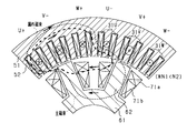
- FIG. 3 is a cross-sectional view of the rotor and the stator
- FIG. 4 is a diagram showing changes in a fundamental wave current, a harmonic current, and the like.
- FIG. 5 is a diagram showing the transition of the three-phase current
- FIG. 6 is a diagram showing changes in the fundamental wave current, the harmonic current, and the like.
- FIG. 7 is a diagram showing the transition of the three-phase current
- FIG. 1 is an overall configuration diagram of a control system for a rotating electric machine according to a first embodiment
- FIG. 2 is a diagram showing an electric circuit provided in the rotor
- FIG. 3 is a cross-sectional view of the rotor and the stator
- FIG. 4 is a diagram showing changes in a fundamental wave current, a harmonic current, and the like.
- FIG. 5
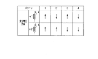
- FIG. 8 is a diagram showing a generation pattern of an induced voltage.
- FIG. 9 is a diagram showing an electric circuit corresponding to patterns 2 and 3.
- FIG. 10 is a diagram showing a series resonance circuit,
- FIG. 11 is a diagram showing a parallel resonance circuit;
- FIG. 12 is a diagram showing a rectifier circuit for a field current.
- FIG. 13 is a time chart showing transitions of currents flowing through the first and second winding portions and the capacitor, respectively.
- FIG. 14 is a time chart showing changes in current flowing through each of the first and second winding portions and the capacitor.
- FIG. 15 is a time chart showing results of actual machine simulations of currents flowing through the first and second winding portions and the capacitors, respectively.
- FIG. 10 is a diagram showing a series resonance circuit
- FIG. 11 is a diagram showing a parallel resonance circuit
- FIG. 12 is a diagram showing a rectifier circuit for a field current.
- FIG. 13 is a time chart showing transitions of currents
- FIG. 16 is a characteristic diagram showing the relationship between the frequency of the harmonic current, the field current, and the torque
- FIG. 17 is a diagram illustrating an electric circuit provided in a rotor according to Modification 2 of the first embodiment.
- FIG. 18 is a diagram illustrating an electric circuit provided in the rotor according to Modification 3 of the first embodiment.
- FIG. 19 is a diagram illustrating an electric circuit provided in a rotor according to Modification 3 of the first embodiment.
- FIG. 20 is a cross-sectional view of the rotor and the stator according to Modification 4 of the first embodiment
- FIG. 21 is a diagram illustrating a flow of a magnetic flux according to the second embodiment
- FIG. 22 is a diagram showing the flow of magnetic flux, FIG.
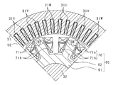
- FIG. 23 is a cross-sectional view of the rotor and the stator according to the third embodiment
- FIG. 24 is an enlarged view of a part of FIG.
- FIG. 25 is a cross-sectional view of the rotor and the stator according to the fourth embodiment
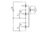
- FIG. 26 is a diagram showing an electric circuit provided in the rotor
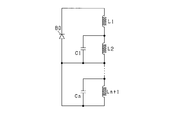
- FIG. 27 is a diagram illustrating an electric circuit provided in a rotor according to a modification of the fourth embodiment.
- the rotating electric machine according to the present embodiment is mounted on, for example, a vehicle.
- parts that are the same or equivalent to each other are given the same reference numerals in the drawings, and the description of the parts with the same reference numerals is used.
- the control system includes a DC power supply 10, an inverter 20, a rotating electric machine 30, and a control device 40.
- a field winding type synchronous machine is used as the rotating electric machine 30.
- the control device 40 controls the rotating electric machine 30 so that the rotating electric machine 30 functions as an ISG (Integrated Starter Generator) or an MG (Motor Generator) which is both a motor and a generator.
- an electromechanical integrated driving device is configured by including the rotating electric machine 30, the inverter 20, and the control device 40, or the rotating electric machine 30, the inverter 20, and the control device 40 are each configured by each component.
- the rotating electric machine 30 includes the rotor 60 having the field winding 70.
- the field winding 70 is composed of a series connection of a first winding 71a and a second winding 71b.
- the field winding 70 is formed by, for example, compression molding. Thereby, the space factor is improved, and the assemblability of the field winding is improved.
- the field winding 70 may be made of, for example, an aluminum wire.
- the aluminum wire has a small specific gravity and can reduce the centrifugal force when the rotor 60 rotates.
- Aluminum wire has lower strength and hardness than copper wire, and is suitable for compression molding.
- the rotating electric machine 30 includes the stator 50 having the stator winding 31.
- the stator winding 31 is made of, for example, a copper wire, and includes U, V, and W-phase windings 31U, 31V, and 31W arranged in a state of being shifted from each other by 120 degrees in electrical angle.
- Inverter 20 includes a series connection of U, V, W phase upper arm switches SUp, SVp, SWp and U, V, W phase lower arm switches SUn, SVn, SWn.
- the U, V, W phase windings 31U, 31V, 31W are connected to the connection points between the U, V, W phase upper arm switches SUp, SVp, SWp and the U, V, W phase lower arm switches SUn, SVn, SWn.
- the second ends of the U, V, W phase windings 31U, 31V, 31W are connected at a neutral point. That is, in the present embodiment, the U, V, and W phase windings 31U, 31V, and 31W are star-connected.
- each of the switches SUp to SWn is an IGBT.
- a freewheel diode is connected in anti-parallel to each of the switches SUp, SVp, SWp, SUn, SVn, and SWn.
- the positive terminal of the DC power supply 10 is connected to the collectors of the U-, V-, and W-phase upper arm switches SUp, SVp, SWp.
- the negative terminal of the DC power supply 10 is connected to the emitters of the U-, V-, and W-phase lower arm switches SUn, SVn, SWn. Note that a smoothing capacitor 11 is connected to the DC power supply 10 in parallel.
- the control system includes an angle detection unit 41.
- the angle detector 41 outputs an angle signal that is a signal corresponding to the rotation angle of the rotor 60.
- the output signal of the angle detection unit 41 is input to the control device 40.
- stator 50 and the rotor 60 will be described.
- Both the stator 50 and the rotor 60 are arranged coaxially with the rotating shaft 32.
- the direction in which the rotating shaft 32 extends is defined as the axial direction
- the direction radially extending from the center of the rotating shaft 32 is defined as the radial direction
- the direction extending circumferentially around the rotating shaft 32 is defined as the circumferential direction.
- the stator 50 is made of a laminated steel sheet made of a soft magnetic material, and has an annular stator core 51 and a plurality of teeth 52 projecting radially inward from the stator core 51.
- the phase windings 31U, 31V, and 31W are distributedly wound or concentratedly wound around the teeth 52.
- 48 teeth are provided at equal intervals in the circumferential direction. For this reason, the rotary electric machine 30 has 48 slots.
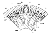
- the rotor 60 is made of a laminated steel sheet made of a soft magnetic material, and has a cylindrical rotor core 61 and a plurality of main poles 62 projecting radially outward from the rotor core 61.
- the front end surface of each main pole portion 62 faces the end surface of the tooth 52.
- eight main pole portions 62 are provided at equal intervals in the circumferential direction.
- each main pole portion 62 the first winding portion 71a is wound radially outside, and the second winding portion 71b is wound radially inside the first winding portion 71a.
- the winding directions of the first winding part 71a and the second winding part 71b are the same. Further, among the main pole portions 62 adjacent in the circumferential direction, the winding directions of the winding portions 71a and 71b wound around one side and the winding directions of the winding portions 71a and 71b wound around the other side are opposite. Has become. For this reason, the magnetization directions of the main pole portions 62 adjacent in the circumferential direction are opposite to each other.
- FIG. 2 shows an electric circuit on the rotor side including the winding portions 71a and 71b wound around the common main pole portion 62.
- the rotor 60 is provided with a diode 80 as a rectifying element and a capacitor 90.
- the cathode of the diode 80 is connected to the first end of the first winding 71a, and the second end of the first winding 71a is connected to the first end of the second winding 71b.
- the anode of the diode 80 is connected to the second end of the second winding part 71b.
- a capacitor 90 is connected in parallel to the second winding part 71b. 2, L1 indicates the inductance of the first winding 71a, L2 indicates the inductance of the second winding 71b, and C indicates the capacitance of the capacitor 90.
- control device 40 will be described. Note that a part or all of the functions of the control device 40 may be configured as hardware by, for example, one or a plurality of integrated circuits. In addition, each function of the control device 40 may be configured by, for example, software recorded on a non-transitional substantial recording medium and a computer that executes the software.
- the control device 40 acquires the angle signal of the angle detection unit 41, and generates a drive signal for turning on and off each of the switches SUp to SWn included in the inverter 20 based on the acquired angle signal. More specifically, when driving the rotating electric machine 30 as an electric motor, the control device 40 converts DC power output from the DC power supply 10 into AC power and supplies the AC power to the U, V, and W phase windings 31U, 31V, and 31W. To this end, a drive signal for turning on / off each of the arm switches SUp to SWn is generated, and the generated drive signal is supplied to the gates of each of the arm switches SUp to SWn.
- control device 40 converts AC power output from U, V, W phase windings 31U, 31V, 31W into DC power and supplies it to DC power supply 10. For this purpose, a drive signal for turning on / off each of the arm switches SUp to SWn is generated.
- the control device 40 turns on and off the switches SUp to SWn so that the combined current of the fundamental wave current and the harmonic current flows through each of the phase windings 31U, 31V, and 31W.
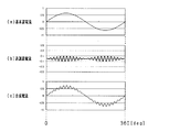
- the fundamental wave current is a current mainly for generating torque in the rotating electric machine 30.
- the harmonic current is a current mainly for exciting the field winding 70 as shown in FIG.
- FIG. 4C shows a phase current as a combined current of the fundamental current and the harmonic current.
- the values on the vertical axis shown in FIG. 4 indicate the relative relationships between the waveform magnitudes shown in FIGS. 4 (a) to 4 (c).
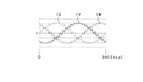
- the phase currents IU, IV, IW flowing through the phase windings 31U, 31V, 31W are shifted by 120 ° in electrical angle as shown in FIG.
- the envelope of the harmonic current has a half cycle of the fundamental current.
- the envelope is shown by the dashed line in FIG.
- the timing at which the envelope reaches its peak value deviates from the timing at which the fundamental current reaches its peak value.
- the timing at which the envelope curve has its peak value is the timing at which the fundamental wave current becomes its fluctuation center (0).
- the control device 40 controls the amplitude and cycle of each of the fundamental wave current and the harmonic current independently.
- the maximum value of the phase current flowing through each phase winding 31U, 31V, 31W can be reduced, and the torque of the rotary electric machine 30 can be commanded without increasing the capacity of the inverter 20. Can be achieved.
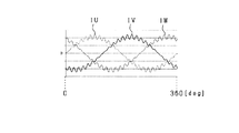
- the harmonic current may be the one shown in FIG. 6B.
- FIGS. 6A and 6C correspond to FIGS. 4A and 4C described above.
- the timing at which the envelope of the harmonic current has its peak value is the timing at which the fundamental current has its peak value.
- the harmonic current shown in FIG. 6B is obtained by shifting the phase of the harmonic current shown in FIG. 4B by 1 / of the period of the fundamental current.
- FIG. 7 shows transition of the phase currents IU, IV, IW flowing through the phase windings 31U, 31V, 31W in this case.
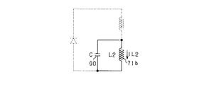
- a series resonance circuit including the first winding unit 71a, the capacitor 90, and the diode 80 is configured, and a parallel resonance circuit including the second winding unit 71b and the capacitor 90 is configured.
- the first resonance frequency, which is the resonance frequency of the series resonance circuit, is f1
- the second resonance frequency, which is the resonance frequency of the parallel resonance circuit is f2.
- the respective resonance frequencies f1 and f2 are represented by the following equations (eq1) and (eq2).
- the capacitor 90 is connected in parallel to the second winding 71b. For this reason, as shown in patterns 2 and 3 in FIG. 8, even when the induced voltages generated in the first and second winding portions 71a and 71b have the opposite polarities, the induced current is generated via the capacitor 90. Flows, the induced currents flowing through the first and second winding portions 71a and 71b are not canceled each other. Therefore, as shown in FIG. 9A, the current induced in the first winding 71a and the current induced in the second winding 71b are transferred to the anode side of the diode 80 via the capacitor 90. 9B, or a current flows from the capacitor 90 to the anode side of the diode 80 via the second winding part 71b, as shown in FIG. 9B. As a result, the field current flowing through the field winding 70 can be increased.
- the frequency fh of the harmonic current flowing through the stator winding 31 is set to the same frequency as the first resonance frequency f1 or a frequency in the vicinity thereof. Therefore, the currents induced in the first and second winding portions 71a and 71b can be further increased, and the field current can be further increased.
- FIG. 2 basically includes three circuits shown in FIGS.
- FIG. 10 illustrates a series resonance circuit including the first winding unit 71a, the capacitor 90, and the diode 80
- FIG. 11 illustrates a parallel resonance circuit including the second winding unit 71b and the capacitor 90
- FIG. 12 shows a field current rectifier circuit including the first and second winding portions 71a and 71b and the diode 80.
- the impedance becomes minimum at the first resonance frequency f1, and the alternating current becomes maximum. Further, since the series resonance circuit includes the diode 80, a half-wave current flows.
- the impedance becomes minimum at the second resonance frequency f2, and the alternating current becomes maximum.
- the frequency of the harmonic current flowing through the stator winding 31 is set to the first resonance frequency f1
- a current that fluctuates at the first resonance frequency f1 is supplied to the capacitor 90 in the series resonance circuit.
- the current supplied to the capacitor 90 becomes a half-wave current by the diode 80.
- the current blocked by the diode 80 in the series resonance circuit is returned to the cathode side of the diode 80 via the second winding part 71b of the parallel resonance circuit.
- the alternating current flowing through each of the series resonance circuit and the parallel resonance circuit has a maximum or a value close to the maximum.
- the current flowing in the circuit shown in FIG. 12 is mainly an AC component current flowing in the circuits shown in FIGS.
- a DC component current rectified by the diode 80 flows.
- FIGS. 13 and 14 show transitions of the current flowing in the circuits shown in FIGS. 13 and 14, IC indicates a capacitor current that is a current flowing through the capacitor 90, and IL1 indicates a current flowing through the first winding unit 71a. IL2 indicates a current flowing through the second winding portion 71b, and If indicates a field current which is a DC component current flowing through the circuit shown in FIG.
- the values on the vertical axis shown in FIGS. 13 and 14 indicate the relative relationship between the magnitudes of the respective waveforms.
- the capacitor current IC is positive when it flows in the direction from the first winding 71a to the capacitor 90, as shown by the arrow in FIG.
- the current IL1 flowing through the first winding portion 71a is positive when the current flows in a direction from the first end to the second end of the first winding portion 71a, as indicated by an arrow in FIG.
- the current IL2 flowing in the second winding part 71b is positive when the current flows in the direction from the first end to the second end of the second winding part 71b as shown by the arrow in FIG.
- the field current If is positive when it flows in the direction from the anode to the cathode of the diode 80 as shown by the arrow in FIG.
- FIG. 13 shows a state immediately after the field winding 70 starts to be excited.
- the capacitor current IC has a positive value. That is, in the first period T1, a current flows from the first winding 71a to the capacitor 90 in the series resonance circuit of FIG.
- the magnitude of the inflowing capacitor current IC is equal to the magnitude of the current IL1 flowing through the first winding 71a.
- the frequency fh of the harmonic current flowing through the stator winding 31 to the first resonance frequency f1
- the alternating current flowing through the series resonance circuit increases.
- the capacitor current IC has a negative value. That is, in the second period T2, in the parallel resonance circuit of FIG. 11, current flows from the capacitor 90 to the second winding part 71b.
- the magnitude of the capacitor current IC flowing out is equal to the magnitude of the positive current IL2 flowing through the second winding part 71b.
- FIG. 15 shows the results of a simulation performed with a configuration equivalent to a real machine model.
- the phase shift ⁇ s between the current IL1 flowing through the first winding 71a and the current IL2 flowing through the second winding 71b is 180 ° in electrical angle. This makes it possible to cancel out the ripple of the combined magnetic field of the magnetic fields generated in the first and second winding portions 71a and 71b, and to make the combined magnetic field a constant magnetic field in which the ripple is smoothed. Can be.
- the phase shift amount ⁇ s may be a value other than 180 ° in “120 ° ⁇ s ⁇ 240 °”. If the shift amount ⁇ s is in the range of 180 ° ⁇ 60 °, it is possible to reduce the ripple of the combined magnetic field of the magnetic field generated by the current flowing through the first winding 71a and the magnetic field generated by the current flowing through the second winding 71b. .
- the inductances L1 and L2 of the first and second winding portions 71a and 71b are set so as to satisfy the following expressions (eq3) and (eq4). Is set.
- this setting will be described.
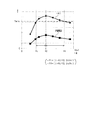
- FIG. 16 shows the relationship between the frequency fh of the harmonic current, the field current flowing through the field winding 70, and the torque of the rotating electric machine 30.
- the torque of the rotating electric machine 30 is maximized at a certain frequency in a range where it is assumed to be used as the frequency fh of the harmonic current.
- the frequency at which the maximum torque is obtained is referred to as a reference frequency f0.
- the reference frequency f0 is a frequency when the first resonance frequency f1 becomes equal to the second resonance frequency f2.
- the torque of the rotating electric machine 30 is set to the allowable lower limit value Tmin or more.
- the allowable lower limit Tmin is set, for example, to a value of 80% to 90% of the maximum torque.
- the lower one of the two frequencies fh of the harmonic current whose torque matches the allowable lower limit Tmin is referred to as a lower limit frequency fL, and the higher one is referred to as an upper limit frequency fH.
- the real numbers A and B are set to, for example, values in the range of “0 ⁇ A ⁇ 0.5, 0 ⁇ B ⁇ 0.5”, and preferably “0 ⁇ A ⁇ 0.4”. , 0 ⁇ B ⁇ 0.4 ”. It is desirable that each of the first resonance frequency f1 and the second resonance frequency f2 be in a frequency range higher than the lower limit frequency fL and lower than the upper limit frequency fH.
- equations (eq6) and (eq7) are derived.
- f1 f2
- the effect of increasing the field current increases.
- L1 and L2 are set so that “L1 ⁇ L2”. Is also good.
- this setting will be described.
- This setting is, for example, a case where the allowable lower limit value Tmin is set to a value of 90% of the maximum torque.
- Tmin the allowable lower limit value
- “1 ⁇ L2 / L1 ⁇ 1.56” and “0.69 ⁇ L1 / L2 ⁇ 1” are derived from the above equations (eq3), (eq4), and (eq16).
- the field current can be increased by setting the inductances L1 and L2 of the first and second winding portions 71a and 71b so as to satisfy the above equations (eq3) and (eq4). .
- Each of the first and second winding portions of the field winding may be formed by a rectangular wire.
- the space factor of the field winding can be increased, and the loss can be reduced.
- the flat wire when a centrifugal force acts on the winding portion, the load applied between the windings can be received on the surface, so that damage to the coating of the winding can be prevented.
- the ampere turn (AT) can be increased, and the excitation range of the field winding can be expanded. As a result, torque controllability is improved.
- each of the first and second winding portions may be configured by ⁇ winding using a flat wire.
- the ⁇ -winding portion using a rectangular wire for example, the winding portion shown in FIG. 5A of JP-A-2008-178211 can be used.
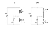
- a Zener diode 81 may be connected in parallel with the rectifier diode 80. Thereby, the surge voltage applied to the diode 80, the field winding 70 and the capacitor 90 can be absorbed, and the deterioration of the diode 80, the field winding 70 and the capacitor 90 can be suppressed.
- the surge voltage may be generated, for example, when a harmonic current flowing through the stator winding 31 is greatly distorted from a sine wave.
- a harmonic current flowing through the stator winding 31 is greatly distorted from a sine wave.
- the stator winding 31 is used to supply a harmonic current.
- the distortion of the harmonic current increases, and the surge voltage tends to increase. Therefore, in a configuration where the surge voltage is likely to be large, the merit of providing the Zener diode 81 is great.
- a Zener diode 81 may be provided instead of the rectifier diode 80.
- the Zener diode 81 has both a rectifying function and a surge absorbing function. As a result, the number of components of the rotating electric machine 30 can be reduced.
- Zener diodes 81 may be provided as shown in FIG. FIG. 19 shows an example in which two Zener diodes 81 are provided.
- a field winding 73 as shown in FIG. 20 may be used. Specifically, a first winding part 74a is wound around the main pole part 62, and a second winding part 74b is wound outside the first winding part 74a.
- the inductance L1 of the first winding 71a can be expressed by the following equation (eq18), and the inductance L2 of the second winding 71b can be expressed by the following equation (eq19).
- ⁇ indicates the magnetic permeability
- S1 and S2 are the magnetic path areas of the magnetic circuit formed when the first and second winding portions 71a and 71b are energized
- M1 and m2 indicate the magnetic path length of the magnetic circuit formed when the first and second winding portions 71a and 71b are energized.
- FIG. 21 shows an example in which S1 / m1 is equivalent to S2 / m2.
- S1 / m1 is equivalent to S2 / m2.
- a state close to no load is shown, and the magnetic flux passes through only a thin broken line.
- FIG. 22 shows another example of this case. This example shows a state near the maximum load.
- partition portion 100 made of a soft magnetic material may be provided between first winding portion 71 a and second winding portion 71 b.
- the partition part 100 has, for example, an annular shape, and the center hole of the partition part 100 is inserted into the main pole part 62.
- the partition part 100 has a flat shape extending in the circumferential direction when viewed from the axial direction. Since the partition part 100 is interposed between the first winding part 71a and the second winding part 71b, the first winding part 71a and the second winding part 71b are cut off in the radial direction by the partition part 100. ing.
- the radial thickness of the partition part 100 is smaller than the radial thickness of each of the first winding part 71a and the second winding part 71b.
- the circumferential length of the partition 100 is equal to or greater than the circumferential length of each of the windings 71a and 71b.
- the partition part 100 may be formed by laminating soft magnetic materials in the radial direction.
- eddy current loss can be reduced.
- the radial thickness can be set to be thin according to the thickness of the steel sheet while securing the circumferential length of the partition part 100.
- a partition may be interposed between the first winding 74a and the second winding 74b.
- the field winding 70 is composed of a series connection of a first winding part 71a, a second winding part 71b, and a third winding part 71c, as shown in FIG.
- the first winding part 71a is wound on the outermost side in the radial direction
- the second winding part 71b is wound on the radially inner side of the first winding part 71a
- the second winding part 71b is wound.
- the third winding portion 71c is wound radially inward of the wire portion 71b.
- the winding directions of the winding portions 71a, 71b, 71c are the same as each other.
- the winding directions of the winding portions 71a, 71b, 71c wound around one side and the winding directions of the winding portions 71a, 71b, 71c wound around the other side Is reversed.
- FIG. 26 shows an electric circuit on the rotor side including the winding portions 71a, 71b and 71c wound around the common main pole portion 62.
- the capacitor 90 is referred to as a first capacitor 90.
- the rotor 60 is provided with a first condenser 90 and a second condenser 91.
- the first end of the third winding part 71c is connected to the second end of the second winding part 71b.
- the anode of the diode 80 is connected to the second end of the third winding 71c.
- a second capacitor 91 is connected in parallel to the third winding 71c.
- L3 indicates the inductance of the third winding portion 71c
- C1 and C2 indicate the capacitance of the first and second capacitors 90 and 91.
- a series resonance circuit including the first winding part 71a, the first capacitor 90, and the diode 80 is referred to as a first series resonance circuit
- a parallel resonance circuit including the second winding part 71b and the first capacitor 90 is referred to as a first resonance circuit. It is referred to as a first parallel resonance circuit.
- a second series resonance circuit including the first and second winding portions 71a and 71b, the second capacitor 91, and the diode 80, and a second series resonance circuit including the third winding portion 71c and the second capacitor 91 are also provided. And a parallel resonance circuit.
- the respective resonance frequencies f3 and f4 are expressed by the following equation (eq20). , (Eq21).
- the second series resonance circuit and the second parallel resonance circuit function similarly to the first series resonance circuit and the first parallel resonance circuit. According to this configuration, for example, even if the frequency of the harmonic current flowing through each of the phase windings 31U, 31V, and 31W deviates from the set frequency, the deviated frequency causes the resonance of the third and fourth resonance circuits.
- the frequencies are f3 and f4
- the effect of increasing the field current can be obtained at those frequencies.
- the phenomenon in which the frequency of the harmonic current deviates from the set frequency may occur, for example, in a region where the electrical angular frequency of the rotating electric machine 30 is high.
- M the number of harmonic currents that can be superimposed in one cycle of the fundamental current (M is a natural number), and the number of superimposed harmonic currents changes from M to M-1
- the field winding may consist of a series connection of four or more winding parts. In this case, as shown in FIG. 27, when the number of winding portions is n + 1, the number of capacitors is n.
- the inductances L1 and L2 of the first and second winding portions 71a and 71b may be set so as to satisfy either one of the above equations (eq3) and (eq4), but not both.
- the inductances L1 and L2 may be set so as to satisfy one of “0.5 ⁇ L2 / L1 ⁇ 2” and “0.5 ⁇ L1 / L2 ⁇ 2”. .
- the rotating electric machine is not limited to the inner rotor type, but may be an outer rotor type.
- the main pole portion protrudes radially inward from the rotor core.
- the field winding of the rotor is not limited to the aluminum wire, but may be, for example, a copper wire or CNT (carbon nanotube). Further, the field winding may not be formed by compression molding.
Landscapes
- Engineering & Computer Science (AREA)
- Power Engineering (AREA)
- Synchronous Machinery (AREA)
- Control Of Ac Motors In General (AREA)
Priority Applications (2)
| Application Number | Priority Date | Filing Date | Title |
|---|---|---|---|
| CN201980062625.1A CN112753156B (zh) | 2018-09-25 | 2019-09-02 | 励磁绕组型旋转电机 |
| US17/205,026 US11870312B2 (en) | 2018-09-25 | 2021-03-18 | Field coil type rotating electric machine |
Applications Claiming Priority (2)
| Application Number | Priority Date | Filing Date | Title |
|---|---|---|---|
| JP2018179512A JP6969529B2 (ja) | 2018-09-25 | 2018-09-25 | 界磁巻線型回転電機 |
| JP2018-179512 | 2018-09-25 |
Related Child Applications (1)
| Application Number | Title | Priority Date | Filing Date |
|---|---|---|---|
| US17/205,026 Continuation US11870312B2 (en) | 2018-09-25 | 2021-03-18 | Field coil type rotating electric machine |
Publications (1)
| Publication Number | Publication Date |
|---|---|
| WO2020066481A1 true WO2020066481A1 (ja) | 2020-04-02 |
Family
ID=69949963
Family Applications (1)
| Application Number | Title | Priority Date | Filing Date |
|---|---|---|---|
| PCT/JP2019/034472 Ceased WO2020066481A1 (ja) | 2018-09-25 | 2019-09-02 | 界磁巻線型回転電機 |
Country Status (4)
| Country | Link |
|---|---|
| US (1) | US11870312B2 (https=) |
| JP (1) | JP6969529B2 (https=) |
| CN (1) | CN112753156B (https=) |
| WO (1) | WO2020066481A1 (https=) |
Families Citing this family (5)
| Publication number | Priority date | Publication date | Assignee | Title |
|---|---|---|---|---|
| JP7259543B2 (ja) * | 2019-05-22 | 2023-04-18 | 株式会社デンソー | 界磁巻線型回転電機 |
| US12170459B2 (en) * | 2021-08-30 | 2024-12-17 | Abb Schweiz Ag | Tapped winding method for extended constant horsepower speed range |
| JP2025015045A (ja) | 2023-07-20 | 2025-01-30 | 株式会社デンソー | 巻線界磁型回転電機 |
| JP2025015046A (ja) | 2023-07-20 | 2025-01-30 | 株式会社デンソー | 巻線界磁型回転電機 |
| CN117097051B (zh) * | 2023-10-20 | 2024-01-02 | 博格华纳汽车零部件(武汉)有限公司 | 一种72槽6极2支路发夹式扁线电枢绕组及电机 |
Citations (6)
| Publication number | Priority date | Publication date | Assignee | Title |
|---|---|---|---|---|
| JP2008178211A (ja) * | 2007-01-18 | 2008-07-31 | Denso Corp | 界磁巻線型同期機 |
| JP2013005575A (ja) * | 2011-06-16 | 2013-01-07 | Toyota Motor Corp | 電磁石型回転電機 |
| JP2014007837A (ja) * | 2012-06-22 | 2014-01-16 | Toyota Motor Corp | 回転電機及び回転電機駆動システム |
| US20160049838A1 (en) * | 2013-03-21 | 2016-02-18 | Feaam Gmbh | Synchronous machine |
| JP2018042401A (ja) * | 2016-09-08 | 2018-03-15 | 株式会社デンソー | 界磁巻線式回転機 |
| JP2018098907A (ja) * | 2016-12-13 | 2018-06-21 | 株式会社デンソー | 界磁巻線型回転機 |
Family Cites Families (19)
| Publication number | Priority date | Publication date | Assignee | Title |
|---|---|---|---|---|
| JP5120586B2 (ja) * | 2005-06-28 | 2013-01-16 | 株式会社デンソー | 界磁巻線型同期機 |
| US7880424B2 (en) * | 2006-09-28 | 2011-02-01 | Denso Corporation | Rotary electric apparatus having rotor with field winding inducing current therethrough for generating magnetic field |
| RU2453981C2 (ru) * | 2007-09-11 | 2012-06-20 | Абб Швайц Аг | Способ и устройство для определения тока возбуждения в бесщеточных электрических машинах |
| JP5403338B2 (ja) | 2009-05-22 | 2014-01-29 | 株式会社デンソー | 同期機 |
| CN103795209B (zh) * | 2012-10-29 | 2016-09-28 | 济南吉美乐电源技术有限公司 | 增磁升压双励磁绕组复励的电励磁双凸极发电机 |
| CN103915964B (zh) * | 2013-01-08 | 2016-03-16 | 济南吉美乐电源技术有限公司 | 两相整流叠加双励磁绕组的四相电励磁双凸极发电机 |
| CN103929031A (zh) * | 2013-01-11 | 2014-07-16 | 济南吉美乐电源技术有限公司 | 复励双励磁绕组分瓣转子磁通切换双凸极无刷直流发电机 |
| US9203338B2 (en) * | 2013-08-05 | 2015-12-01 | GM Global Technology Operations LLC | Electric power assembly for a vehicle |
| US9813004B2 (en) * | 2015-01-16 | 2017-11-07 | Abb Schweiz Ag | Systems and methods concerning exciterless synchronous machines |
| JP2016201874A (ja) * | 2015-04-08 | 2016-12-01 | スズキ株式会社 | 回転電機 |
| JP6464917B2 (ja) * | 2015-05-13 | 2019-02-06 | 株式会社デンソー | 界磁巻線型同期機 |
| JP6561693B2 (ja) * | 2015-08-31 | 2019-08-21 | スズキ株式会社 | 回転電機 |
| JP6544151B2 (ja) * | 2015-08-31 | 2019-07-17 | スズキ株式会社 | 回転電機 |
| JP2017050942A (ja) * | 2015-08-31 | 2017-03-09 | スズキ株式会社 | 回転電機 |
| JP6485316B2 (ja) * | 2015-10-16 | 2019-03-20 | スズキ株式会社 | 回転電機 |
| JP6579379B2 (ja) * | 2015-12-21 | 2019-09-25 | 株式会社デンソー | 界磁巻線型同期機駆動システム |
| DE102016224916A1 (de) * | 2016-12-14 | 2018-06-14 | Bayerische Motoren Werke Aktiengesellschaft | Rotor und Rotorschaltung für einen Elektromotor |
| WO2018117144A1 (ja) * | 2016-12-21 | 2018-06-28 | 株式会社デンソー | 界磁巻線型回転電機 |
| JP6646878B2 (ja) * | 2016-12-21 | 2020-02-14 | 株式会社デンソー | 界磁巻線型回転機 |
-
2018
- 2018-09-25 JP JP2018179512A patent/JP6969529B2/ja active Active
-
2019
- 2019-09-02 CN CN201980062625.1A patent/CN112753156B/zh active Active
- 2019-09-02 WO PCT/JP2019/034472 patent/WO2020066481A1/ja not_active Ceased
-
2021
- 2021-03-18 US US17/205,026 patent/US11870312B2/en active Active
Patent Citations (6)
| Publication number | Priority date | Publication date | Assignee | Title |
|---|---|---|---|---|
| JP2008178211A (ja) * | 2007-01-18 | 2008-07-31 | Denso Corp | 界磁巻線型同期機 |
| JP2013005575A (ja) * | 2011-06-16 | 2013-01-07 | Toyota Motor Corp | 電磁石型回転電機 |
| JP2014007837A (ja) * | 2012-06-22 | 2014-01-16 | Toyota Motor Corp | 回転電機及び回転電機駆動システム |
| US20160049838A1 (en) * | 2013-03-21 | 2016-02-18 | Feaam Gmbh | Synchronous machine |
| JP2018042401A (ja) * | 2016-09-08 | 2018-03-15 | 株式会社デンソー | 界磁巻線式回転機 |
| JP2018098907A (ja) * | 2016-12-13 | 2018-06-21 | 株式会社デンソー | 界磁巻線型回転機 |
Also Published As
| Publication number | Publication date |
|---|---|
| JP2020054064A (ja) | 2020-04-02 |
| US11870312B2 (en) | 2024-01-09 |
| JP6969529B2 (ja) | 2021-11-24 |
| CN112753156B (zh) | 2023-12-05 |
| US20210226499A1 (en) | 2021-07-22 |
| CN112753156A (zh) | 2021-05-04 |
Similar Documents
| Publication | Publication Date | Title |
|---|---|---|
| WO2020066481A1 (ja) | 界磁巻線型回転電機 | |
| JP7259543B2 (ja) | 界磁巻線型回転電機 | |
| JP7095532B2 (ja) | 界磁巻線型回転電機 | |
| US20240006967A1 (en) | Field winding type rotating electric machine | |
| CN111712999B (zh) | 励磁绕组型旋转电机 | |
| JP2016226098A (ja) | 回転電機 | |
| CN1118921C (zh) | 带增强转子场系的无电刷三相同步发电机 | |
| WO2016117217A1 (ja) | 永久磁石式回転電機 | |
| KR101767002B1 (ko) | 권선형 동기전동기 및 권선형 동기전동기의 구동방법 | |
| JP2020043654A (ja) | モータ | |
| JP2014007837A (ja) | 回転電機及び回転電機駆動システム | |
| CN106487176B (zh) | 旋转电机 | |
| US20240128844A1 (en) | High-power multiphase electric machine with reduced mutual inductance interaction | |
| Jiang et al. | Comparison between conventional and novel self-excited synchronous motors | |
| JP2013005676A (ja) | 電磁石型回転電機 | |
| JP2020043655A (ja) | モータ | |
| CN121925776A (zh) | 旋转电机 | |
| WO2019009194A1 (ja) | コンシクエント型モータ | |
| Zheng | Novel stator wound field synchronous machines with permanent magnets on slot openings | |
| JP2017184467A (ja) | 回転電機 |
Legal Events
| Date | Code | Title | Description |
|---|---|---|---|
| 121 | Ep: the epo has been informed by wipo that ep was designated in this application |
Ref document number: 19864537 Country of ref document: EP Kind code of ref document: A1 |
|
| NENP | Non-entry into the national phase |
Ref country code: DE |
|
| 122 | Ep: pct application non-entry in european phase |
Ref document number: 19864537 Country of ref document: EP Kind code of ref document: A1 |