WO2020054777A1 - ペレットの製造方法、ペレット及びイオン交換膜 - Google Patents
ペレットの製造方法、ペレット及びイオン交換膜 Download PDFInfo
- Publication number
- WO2020054777A1 WO2020054777A1 PCT/JP2019/035752 JP2019035752W WO2020054777A1 WO 2020054777 A1 WO2020054777 A1 WO 2020054777A1 JP 2019035752 W JP2019035752 W JP 2019035752W WO 2020054777 A1 WO2020054777 A1 WO 2020054777A1
- Authority
- WO
- WIPO (PCT)
- Prior art keywords
- group
- ion exchange
- converted
- fluoropolymer
- pellet
- Prior art date
- Legal status (The legal status is an assumption and is not a legal conclusion. Google has not performed a legal analysis and makes no representation as to the accuracy of the status listed.)
- Ceased
Links
Images

Classifications
-
- C—CHEMISTRY; METALLURGY
- C25—ELECTROLYTIC OR ELECTROPHORETIC PROCESSES; APPARATUS THEREFOR
- C25B—ELECTROLYTIC OR ELECTROPHORETIC PROCESSES FOR THE PRODUCTION OF COMPOUNDS OR NON-METALS; APPARATUS THEREFOR
- C25B13/00—Diaphragms; Spacing elements
- C25B13/04—Diaphragms; Spacing elements characterised by the material
- C25B13/08—Diaphragms; Spacing elements characterised by the material based on organic materials
-
- C—CHEMISTRY; METALLURGY
- C08—ORGANIC MACROMOLECULAR COMPOUNDS; THEIR PREPARATION OR CHEMICAL WORKING-UP; COMPOSITIONS BASED THEREON
- C08F—MACROMOLECULAR COMPOUNDS OBTAINED BY REACTIONS ONLY INVOLVING CARBON-TO-CARBON UNSATURATED BONDS
- C08F214/00—Copolymers of compounds having one or more unsaturated aliphatic radicals, each having only one carbon-to-carbon double bond, and at least one being terminated by a halogen
- C08F214/18—Monomers containing fluorine
- C08F214/182—Monomers containing fluorine not covered by the groups C08F214/20 - C08F214/28
-
- B—PERFORMING OPERATIONS; TRANSPORTING
- B29—WORKING OF PLASTICS; WORKING OF SUBSTANCES IN A PLASTIC STATE IN GENERAL
- B29B—PREPARATION OR PRETREATMENT OF THE MATERIAL TO BE SHAPED; MAKING GRANULES OR PREFORMS; RECOVERY OF PLASTICS OR OTHER CONSTITUENTS OF WASTE MATERIAL CONTAINING PLASTICS
- B29B9/00—Making granules
- B29B9/02—Making granules by dividing preformed material
- B29B9/06—Making granules by dividing preformed material in the form of filamentary material, e.g. combined with extrusion
-
- B—PERFORMING OPERATIONS; TRANSPORTING
- B29—WORKING OF PLASTICS; WORKING OF SUBSTANCES IN A PLASTIC STATE IN GENERAL
- B29B—PREPARATION OR PRETREATMENT OF THE MATERIAL TO BE SHAPED; MAKING GRANULES OR PREFORMS; RECOVERY OF PLASTICS OR OTHER CONSTITUENTS OF WASTE MATERIAL CONTAINING PLASTICS
- B29B9/00—Making granules
- B29B9/12—Making granules characterised by structure or composition
-
- B—PERFORMING OPERATIONS; TRANSPORTING
- B29—WORKING OF PLASTICS; WORKING OF SUBSTANCES IN A PLASTIC STATE IN GENERAL
- B29B—PREPARATION OR PRETREATMENT OF THE MATERIAL TO BE SHAPED; MAKING GRANULES OR PREFORMS; RECOVERY OF PLASTICS OR OTHER CONSTITUENTS OF WASTE MATERIAL CONTAINING PLASTICS
- B29B9/00—Making granules
- B29B9/16—Auxiliary treatment of granules
-
- B—PERFORMING OPERATIONS; TRANSPORTING
- B29—WORKING OF PLASTICS; WORKING OF SUBSTANCES IN A PLASTIC STATE IN GENERAL
- B29C—SHAPING OR JOINING OF PLASTICS; SHAPING OF MATERIAL IN A PLASTIC STATE, NOT OTHERWISE PROVIDED FOR; AFTER-TREATMENT OF THE SHAPED PRODUCTS, e.g. REPAIRING
- B29C48/00—Extrusion moulding, i.e. expressing the moulding material through a die or nozzle which imparts the desired form; Apparatus therefor
- B29C48/25—Component parts, details or accessories; Auxiliary operations
- B29C48/78—Thermal treatment of the extrusion moulding material or of preformed parts or layers, e.g. by heating or cooling
- B29C48/86—Thermal treatment of the extrusion moulding material or of preformed parts or layers, e.g. by heating or cooling at the nozzle zone
-
- C—CHEMISTRY; METALLURGY
- C08—ORGANIC MACROMOLECULAR COMPOUNDS; THEIR PREPARATION OR CHEMICAL WORKING-UP; COMPOSITIONS BASED THEREON
- C08F—MACROMOLECULAR COMPOUNDS OBTAINED BY REACTIONS ONLY INVOLVING CARBON-TO-CARBON UNSATURATED BONDS
- C08F214/00—Copolymers of compounds having one or more unsaturated aliphatic radicals, each having only one carbon-to-carbon double bond, and at least one being terminated by a halogen
- C08F214/18—Monomers containing fluorine
- C08F214/26—Tetrafluoroethene
- C08F214/262—Tetrafluoroethene with fluorinated vinyl ethers
-
- C—CHEMISTRY; METALLURGY
- C08—ORGANIC MACROMOLECULAR COMPOUNDS; THEIR PREPARATION OR CHEMICAL WORKING-UP; COMPOSITIONS BASED THEREON
- C08F—MACROMOLECULAR COMPOUNDS OBTAINED BY REACTIONS ONLY INVOLVING CARBON-TO-CARBON UNSATURATED BONDS
- C08F216/00—Copolymers of compounds having one or more unsaturated aliphatic radicals, each having only one carbon-to-carbon double bond, and at least one being terminated by an alcohol, ether, aldehydo, ketonic, acetal or ketal radical
- C08F216/12—Copolymers of compounds having one or more unsaturated aliphatic radicals, each having only one carbon-to-carbon double bond, and at least one being terminated by an alcohol, ether, aldehydo, ketonic, acetal or ketal radical by an ether radical
- C08F216/14—Monomers containing only one unsaturated aliphatic radical
- C08F216/1408—Monomers containing halogen
-
- C—CHEMISTRY; METALLURGY
- C08—ORGANIC MACROMOLECULAR COMPOUNDS; THEIR PREPARATION OR CHEMICAL WORKING-UP; COMPOSITIONS BASED THEREON
- C08F—MACROMOLECULAR COMPOUNDS OBTAINED BY REACTIONS ONLY INVOLVING CARBON-TO-CARBON UNSATURATED BONDS
- C08F216/00—Copolymers of compounds having one or more unsaturated aliphatic radicals, each having only one carbon-to-carbon double bond, and at least one being terminated by an alcohol, ether, aldehydo, ketonic, acetal or ketal radical
- C08F216/12—Copolymers of compounds having one or more unsaturated aliphatic radicals, each having only one carbon-to-carbon double bond, and at least one being terminated by an alcohol, ether, aldehydo, ketonic, acetal or ketal radical by an ether radical
- C08F216/14—Monomers containing only one unsaturated aliphatic radical
- C08F216/1466—Monomers containing sulfur
- C08F216/1475—Monomers containing sulfur and oxygen
-
- C—CHEMISTRY; METALLURGY
- C08—ORGANIC MACROMOLECULAR COMPOUNDS; THEIR PREPARATION OR CHEMICAL WORKING-UP; COMPOSITIONS BASED THEREON
- C08F—MACROMOLECULAR COMPOUNDS OBTAINED BY REACTIONS ONLY INVOLVING CARBON-TO-CARBON UNSATURATED BONDS
- C08F8/00—Chemical modification by after-treatment
- C08F8/12—Hydrolysis
-
- C—CHEMISTRY; METALLURGY
- C08—ORGANIC MACROMOLECULAR COMPOUNDS; THEIR PREPARATION OR CHEMICAL WORKING-UP; COMPOSITIONS BASED THEREON
- C08F—MACROMOLECULAR COMPOUNDS OBTAINED BY REACTIONS ONLY INVOLVING CARBON-TO-CARBON UNSATURATED BONDS
- C08F8/00—Chemical modification by after-treatment
- C08F8/44—Preparation of metal salts or ammonium salts
-
- C—CHEMISTRY; METALLURGY
- C08—ORGANIC MACROMOLECULAR COMPOUNDS; THEIR PREPARATION OR CHEMICAL WORKING-UP; COMPOSITIONS BASED THEREON
- C08J—WORKING-UP; GENERAL PROCESSES OF COMPOUNDING; AFTER-TREATMENT NOT COVERED BY SUBCLASSES C08B, C08C, C08F, C08G or C08H
- C08J3/00—Processes of treating or compounding macromolecular substances
- C08J3/12—Powdering or granulating
-
- C—CHEMISTRY; METALLURGY
- C08—ORGANIC MACROMOLECULAR COMPOUNDS; THEIR PREPARATION OR CHEMICAL WORKING-UP; COMPOSITIONS BASED THEREON
- C08J—WORKING-UP; GENERAL PROCESSES OF COMPOUNDING; AFTER-TREATMENT NOT COVERED BY SUBCLASSES C08B, C08C, C08F, C08G or C08H
- C08J5/00—Manufacture of articles or shaped materials containing macromolecular substances
- C08J5/20—Manufacture of shaped structures of ion-exchange resins
- C08J5/22—Films, membranes or diaphragms
- C08J5/2206—Films, membranes or diaphragms based on organic and/or inorganic macromolecular compounds
- C08J5/2218—Synthetic macromolecular compounds
- C08J5/2231—Synthetic macromolecular compounds based on macromolecular compounds obtained by reactions involving unsaturated carbon-to-carbon bonds
- C08J5/2237—Synthetic macromolecular compounds based on macromolecular compounds obtained by reactions involving unsaturated carbon-to-carbon bonds containing fluorine
-
- B—PERFORMING OPERATIONS; TRANSPORTING
- B29—WORKING OF PLASTICS; WORKING OF SUBSTANCES IN A PLASTIC STATE IN GENERAL
- B29K—INDEXING SCHEME ASSOCIATED WITH SUBCLASSES B29B, B29C OR B29D, RELATING TO MOULDING MATERIALS OR TO MATERIALS FOR MOULDS, REINFORCEMENTS, FILLERS OR PREFORMED PARTS, e.g. INSERTS
- B29K2027/00—Use of polyvinylhalogenides or derivatives thereof as moulding material
- B29K2027/12—Use of polyvinylhalogenides or derivatives thereof as moulding material containing fluorine
- B29K2027/16—PVDF, i.e. polyvinylidene fluoride
-
- B—PERFORMING OPERATIONS; TRANSPORTING
- B29—WORKING OF PLASTICS; WORKING OF SUBSTANCES IN A PLASTIC STATE IN GENERAL
- B29K—INDEXING SCHEME ASSOCIATED WITH SUBCLASSES B29B, B29C OR B29D, RELATING TO MOULDING MATERIALS OR TO MATERIALS FOR MOULDS, REINFORCEMENTS, FILLERS OR PREFORMED PARTS, e.g. INSERTS
- B29K2027/00—Use of polyvinylhalogenides or derivatives thereof as moulding material
- B29K2027/12—Use of polyvinylhalogenides or derivatives thereof as moulding material containing fluorine
- B29K2027/18—PTFE, i.e. polytetrafluoroethylene, e.g. ePTFE, i.e. expanded polytetrafluoroethylene
-
- C—CHEMISTRY; METALLURGY
- C08—ORGANIC MACROMOLECULAR COMPOUNDS; THEIR PREPARATION OR CHEMICAL WORKING-UP; COMPOSITIONS BASED THEREON
- C08J—WORKING-UP; GENERAL PROCESSES OF COMPOUNDING; AFTER-TREATMENT NOT COVERED BY SUBCLASSES C08B, C08C, C08F, C08G or C08H
- C08J2327/00—Characterised by the use of homopolymers or copolymers of compounds having one or more unsaturated aliphatic radicals, each having only one carbon-to-carbon double bond, and at least one being terminated by a halogen; Derivatives of such polymers
- C08J2327/02—Characterised by the use of homopolymers or copolymers of compounds having one or more unsaturated aliphatic radicals, each having only one carbon-to-carbon double bond, and at least one being terminated by a halogen; Derivatives of such polymers not modified by chemical after-treatment
- C08J2327/12—Characterised by the use of homopolymers or copolymers of compounds having one or more unsaturated aliphatic radicals, each having only one carbon-to-carbon double bond, and at least one being terminated by a halogen; Derivatives of such polymers not modified by chemical after-treatment containing fluorine atoms
-
- C—CHEMISTRY; METALLURGY
- C08—ORGANIC MACROMOLECULAR COMPOUNDS; THEIR PREPARATION OR CHEMICAL WORKING-UP; COMPOSITIONS BASED THEREON
- C08J—WORKING-UP; GENERAL PROCESSES OF COMPOUNDING; AFTER-TREATMENT NOT COVERED BY SUBCLASSES C08B, C08C, C08F, C08G or C08H
- C08J2327/00—Characterised by the use of homopolymers or copolymers of compounds having one or more unsaturated aliphatic radicals, each having only one carbon-to-carbon double bond, and at least one being terminated by a halogen; Derivatives of such polymers
- C08J2327/02—Characterised by the use of homopolymers or copolymers of compounds having one or more unsaturated aliphatic radicals, each having only one carbon-to-carbon double bond, and at least one being terminated by a halogen; Derivatives of such polymers not modified by chemical after-treatment
- C08J2327/12—Characterised by the use of homopolymers or copolymers of compounds having one or more unsaturated aliphatic radicals, each having only one carbon-to-carbon double bond, and at least one being terminated by a halogen; Derivatives of such polymers not modified by chemical after-treatment containing fluorine atoms
- C08J2327/18—Homopolymers or copolymers of tetrafluoroethylene
-
- C—CHEMISTRY; METALLURGY
- C08—ORGANIC MACROMOLECULAR COMPOUNDS; THEIR PREPARATION OR CHEMICAL WORKING-UP; COMPOSITIONS BASED THEREON
- C08J—WORKING-UP; GENERAL PROCESSES OF COMPOUNDING; AFTER-TREATMENT NOT COVERED BY SUBCLASSES C08B, C08C, C08F, C08G or C08H
- C08J2333/00—Characterised by the use of homopolymers or copolymers of compounds having one or more unsaturated aliphatic radicals, each having only one carbon-to-carbon double bond, and only one being terminated by only one carboxyl radical, or of salts, anhydrides, esters, amides, imides, or nitriles thereof; Derivatives of such polymers
- C08J2333/04—Characterised by the use of homopolymers or copolymers of compounds having one or more unsaturated aliphatic radicals, each having only one carbon-to-carbon double bond, and only one being terminated by only one carboxyl radical, or of salts, anhydrides, esters, amides, imides, or nitriles thereof; Derivatives of such polymers esters
- C08J2333/14—Characterised by the use of homopolymers or copolymers of compounds having one or more unsaturated aliphatic radicals, each having only one carbon-to-carbon double bond, and only one being terminated by only one carboxyl radical, or of salts, anhydrides, esters, amides, imides, or nitriles thereof; Derivatives of such polymers esters of esters containing halogen, nitrogen, sulfur, or oxygen atoms in addition to the carboxy oxygen
- C08J2333/16—Homopolymers or copolymers of esters containing halogen atoms
-
- Y—GENERAL TAGGING OF NEW TECHNOLOGICAL DEVELOPMENTS; GENERAL TAGGING OF CROSS-SECTIONAL TECHNOLOGIES SPANNING OVER SEVERAL SECTIONS OF THE IPC; TECHNICAL SUBJECTS COVERED BY FORMER USPC CROSS-REFERENCE ART COLLECTIONS [XRACs] AND DIGESTS
- Y02—TECHNOLOGIES OR APPLICATIONS FOR MITIGATION OR ADAPTATION AGAINST CLIMATE CHANGE
- Y02E—REDUCTION OF GREENHOUSE GAS [GHG] EMISSIONS, RELATED TO ENERGY GENERATION, TRANSMISSION OR DISTRIBUTION
- Y02E60/00—Enabling technologies; Technologies with a potential or indirect contribution to GHG emissions mitigation
- Y02E60/30—Hydrogen technology
- Y02E60/50—Fuel cells
Definitions
- the present invention relates to a method for producing a pellet, a pellet, and an ion exchange membrane.
- ion exchange membranes containing a fluorine-containing polymer having an ion exchange group are used.
- a method for producing an ion exchange membrane containing a fluoropolymer a method is known in which a pellet of a fluoropolymer having an ion exchange group or a group that can be converted to an ion exchange group is used as a raw material (see Patent Document 1).
- electrolysis devices including ion exchange membranes are required to have excellent electrolysis voltage stability (a small fluctuation range of electrolysis voltage) from the viewpoint of production efficiency.
- electrolysis voltage stability a small fluctuation range of electrolysis voltage
- the inventor applied an ion exchange membrane obtained by using the fluoropolymer pellets described in Patent Document 1 to an electrolysis apparatus, it was found that the fluctuation range of the electrolysis voltage was large and there was room for improvement. .
- an object of the present invention is to provide a pellet manufacturing method, a pellet, and an ion exchange membrane capable of obtaining an ion exchange membrane having excellent stability of an electrolytic voltage.
- the present inventors have conducted intensive studies to achieve the above object, and as a result, when producing a pellet containing a fluoropolymer using a fluoropolymer having a group that can be converted to an ion exchange group, a group that can be converted to an ion exchange group is used.
- An ion exchange capacity when converted into an ion exchange group is 1.1 meq / g dry resin (hereinafter, also referred to as meq / g resin) or more, and a melt of the fluoropolymer is melt-kneaded.
- the present inventors have found that the desired effect can be obtained by setting the temperature of the die at the time of extruding from the die to less than 200 ° C., and thus the present invention has been achieved.
- a melt containing a fluorine-containing polymer having a group that can be converted to an ion-exchange group is extruded from a die of a melt extruder to obtain a strand containing the fluorine-containing polymer, and then the strand is cut to obtain the fluorine-containing polymer.
- a method for producing a pellet to obtain a pellet containing a polymer The temperature of the die when extruding the melt containing the fluoropolymer from the die is less than 200 ° C., A method for producing pellets, wherein the ion exchange capacity of the fluoropolymer when the group that can be converted to the ion exchange group of the fluoropolymer is converted to an ion exchange group is 1.1 meq / g resin or more. [2] The method of the above-mentioned [1], wherein the strand is cut to obtain a pellet containing a fluoropolymer having a light transmittance of 30 to 60%.
- a 1 is a group that can be converted into a carboxylic acid type functional group
- p is an integer of 0 or 1
- q is q.
- Is an integer of 0 to 12.
- r is an integer of 0 to 3.
- s is an integer of 0 or 1.
- t is an integer of 0 to 12.
- u is an integer of 0 to 3.
- CF 2 CF-L- (A) n (L is an n + 1-valent perfluorohydrocarbon group which may contain an oxygen atom. N is 1 or 2. A is a group which can be converted to a sulfonic acid type functional group.)
- the monomer represented by the formula (2) is a compound represented by the formula (2-1), a compound represented by the formula (2-2), or a compound represented by the formula (2-3) The production method of the above-mentioned [6], which is a compound.
- Formula (2-2): CF 2 CF-R f1 -A
- R f1 is a perfluoroalkylene group which may contain an oxygen atom between carbon atoms.
- R f2 is a single bond or a perfluoroalkylene which may contain an oxygen atom between carbon atoms.
- A is as described in Formula 2 (B).)
- the ion exchange capacity of the fluoropolymer when the group that can be converted to the ion exchange group of the fluoropolymer is converted to an ion exchange group is 1.1 meq / g resin or more,
- the pellet of the above-mentioned [9], wherein the group convertible to the ion exchange group is a group convertible to a carboxylic acid type functional group or a group convertible to a sulfonic acid type functional group.
- the pressure fluctuation at the time of film formation which forms an ion exchange membrane is suppressed, and the ion exchange membrane excellent in the uniformity of a film thickness is obtained.
- a method for producing a pellet, a pellet, and an ion-exchange membrane that can suppress the formation of an ion-exchange membrane and that can form an ion-exchange membrane with excellent electrolysis voltage stability.
- Example 3 shows a photograph (30 times magnification) of the appearance of the pellet obtained in Example 1.
- the meanings of the terms in the present invention are as follows.
- the “ion exchange group” is a group capable of exchanging at least a part of ions contained in this group with another ion, and examples thereof include the following sulfonic acid type functional groups and carboxylic acid type functional groups.
- the “sulfonic acid type functional group” means a sulfonic acid group (—SO 3 H) or a sulfonic acid group (—SO 3 M 2, where M 2 is an alkali metal or quaternary ammonium cation). I do.
- the “carboxylic acid type functional group” means a carboxylic acid group (—COOH) or a carboxylic acid base (—COOM 1, where M 1 is an alkali metal or quaternary ammonium cation).
- the “precursor membrane” is a membrane containing a polymer having a group that can be converted into an ion exchange group.
- the “group that can be converted into an ion-exchange group” means a group that can be converted into an ion-exchange group by a treatment such as a hydrolysis treatment, an acid-formation treatment, or a salt exchange with a metal cation.
- the “group that can be converted into a sulfonic acid type functional group” means a group that can be converted into a sulfonic acid type functional group by a treatment such as a hydrolysis treatment or an acidification treatment.
- the “group that can be converted into a carboxylic acid type functional group” means a group that can be converted into a carboxylic acid type functional group by a known treatment such as a hydrolysis treatment and an acidification treatment.
- “Perfluorohydrocarbon group” means a hydrocarbon group in which all of the hydrogen atoms have been replaced with fluorine atoms.
- Perfluoroaliphatic hydrocarbon group means an aliphatic hydrocarbon group in which all of the hydrogen atoms have been replaced with fluorine atoms.
- The“ unit ”in the polymer means an atomic group derived from one molecule of the monomer, formed by polymerization of the monomer.
- the unit may be an atomic group formed directly by a polymerization reaction, or an atomic group obtained by treating a polymer obtained by a polymerization reaction and converting a part of the atomic group to another structure. .
- “Reinforcing material” means a material used to improve the strength of the ion exchange membrane.
- a material derived from a reinforcing cloth is preferable.
- “Reinforcing cloth” means a cloth used as a raw material of a reinforcing material for improving the strength of an ion exchange membrane.
- the “reinforcing yarn” is a yarn that constitutes a reinforcing cloth, and is a yarn that does not elute under the operating environment of an apparatus including an ion exchange membrane.
- the “reinforcing yarn” a yarn made of a material that does not elute when the reinforcing cloth is immersed in an alkaline aqueous solution (for example, an aqueous solution of sodium hydroxide having a concentration of 32% by mass) is preferable.
- the “sacrifice yarn” is a yarn that constitutes the reinforcing cloth, and is a yarn at least a part of which is eluted under the operating environment of the device including the ion exchange membrane.
- a yarn made of a material that elutes in the alkaline aqueous solution when the reinforcing cloth is immersed in the alkaline aqueous solution is preferable.
- the numerical range represented by using “to” means a range including the numerical values described before and after “to” as the lower limit and the upper limit. When the units of the lower limit and the upper limit are the same, the unit of the lower limit may be omitted.
- the method for producing pellets of the present invention includes a melt containing a fluoropolymer having a group that can be converted into an ion exchange group (hereinafter, also referred to as a fluoropolymer (I ′)).
- a fluoropolymer (I ′) This is a method for producing pellets by extruding from a die of a melt extruder to obtain a strand containing the fluoropolymer (I ′), and then cutting the strand to obtain a pellet containing the fluoropolymer (I ′).
- the temperature of the die at the time of extruding the melt containing the fluoropolymer (I ′) from the die is less than 200 ° C.
- the ions of the fluoropolymer hereinafter, also referred to as fluoropolymer (I)
- the exchange capacity is 1.1 meq / g resin or more.
- a pellet capable of forming an ion exchange membrane having excellent stability of the electrolytic voltage can be obtained.
- the details of this reason have not been clarified, but are presumed to be due to the following reasons. 1
- One of the causes of the variation in the electrolytic voltage is non-uniformity of the thickness of the ion exchange membrane.
- Such non-uniformity of the film thickness of the ion exchange membrane is caused by sticking of the pellets when producing a film-like ion exchange membrane using the pellets containing the fluoropolymer (I ′), and the pressure during the film formation. It is considered that this occurs due to the large fluctuation.
- the sticking between the pellets becomes remarkable when a fluoropolymer having a high ion exchange capacity is used as a raw material, when a group that can be converted into an ion exchange group can be converted into an ion exchange group.
- a fluoropolymer having a group that can be converted into an ion exchange group is supplied to a melt extruder to obtain a melt of the fluoropolymer.
- Known devices can be used as the melt extruder, and specific examples include a single screw extruder, a twin screw extruder, and a tandem extruder.
- the melting temperature of the fluoropolymer (I ′) is preferably from 150 to 350 ° C., particularly preferably from 200 to 300 ° C.
- the melt of the fluoropolymer (I ′) is extruded from a die at the tip of the melt extruder, and cooled to obtain a strand containing the fluoropolymer (I ′). Cut into pieces. Thus, a pellet containing the fluoropolymer (I ′) is obtained.
- a so-called strand cut method is used as a method for cutting the pellets has been described, but an underwater cut method, a hot cut method, or the like may be used.
- the temperature of the die when the melt containing the fluoropolymer (I ′) is extruded from the die (hereinafter, simply referred to as the die temperature) is less than 200 ° C., and the stability of the electrolytic voltage is low.
- the temperature is preferably 190 ° C. or lower, more preferably 170 ° C. or lower, particularly preferably 150 ° C. or lower, and most preferably 145 ° C. or lower.
- the die temperature is preferably 140 ° C. or higher, more preferably 142 ° C. or higher, from the viewpoint of facilitating extrusion of the melt of the fluoropolymer (I ′) from the die.
- the ion-exchange capacity of the fluoropolymer (that is, the fluoropolymer (I)) when the group that can be converted into the ion-exchange group of the fluoropolymer (I ′) is converted to an ion-exchange group is 1.2 meq / g.
- the die temperature is preferably 140 ° C. or more and less than 200 ° C., more preferably 140-150 ° C., and particularly preferably 140-145 ° C., from the viewpoint of more excellent electrolysis voltage stability and more excellent electrolysis efficiency. preferable.
- the shape of the pellet obtained by the present production method is not particularly limited, and may be any shape such as a sphere (including an ellipsoid) and a column (eg, a column).
- the size of the pellet obtained by the present production method is not particularly limited. For example, when the pellet is columnar, the diameter is preferably 2 to 3 mm and the length is preferably 2 to 3 mm.
- the groove formed on the surface of the pellet may be formed on the entire surface of the pellet, but is usually preferably formed only on the side surface (other than the cut surface of the strand) of the pellet.
- the groove formed on the surface of the pellet is preferably formed mainly along a direction intersecting the cut surface of the pellet (strand flow direction).
- a roughening treatment for roughening the surface of the pellet may be performed.
- the surface of the pellet is roughened, and the sticking between the pellets can be further suppressed, so that an ion exchange membrane having more excellent stability of the electrolytic voltage can be obtained.
- a specific example of the method of the surface roughening treatment there is a method of stirring the pellets using a mixer (for example, a V blender).
- Pellets obtained by this production method are preferably used for producing an ion exchange membrane. Specific examples of uses of the ion exchange membrane will be described later.
- the fluoropolymer (I ′) used in the present production method is a fluoropolymer having a group that can be converted into an ion exchange group.
- the group that can be converted to an ion exchange group preferably includes a group that can be converted to a carboxylic acid type functional group or a group that can be converted to a sulfonic acid type functional group.
- the ion exchange capacity of the fluoropolymer (that is, the fluoropolymer (I)) when the group that can be converted to the ion exchange group of the fluoropolymer (I ′) is converted to an ion exchange group is 1.1 meq / g resin or more. From the viewpoint that the electrolysis voltage of the device can be reduced, 1.20 meq / g resin or more is particularly preferable, and from the viewpoint that the strength of the ion exchange membrane is more excellent, it is preferably 2.00 meq / g resin or less, and 1.90 meq / g. Particularly preferred are resins and below.
- the fluoropolymer (I) for measuring the ion exchange capacity is obtained as follows.
- the substrate is immersed at 30 ° C. for 30 minutes to hydrolyze a group that can be converted into an ion exchange group in the fluorine-containing polymer (I ′), convert the group into a K-type ion exchange group, and then wash with water.
- the fluoropolymer (I ′) is a fluoropolymer having a group that can be converted into a carboxylic acid-type functional group (hereinafter, also referred to as a fluoropolymer (C ′)) from the viewpoint that the effects of the present invention can be more exerted, or And a fluorinated polymer having a group that can be converted into a sulfonic acid type functional group (hereinafter, also referred to as a fluorinated polymer (S ′)).
- C ′ carboxylic acid-type functional group
- S ′ fluorinated polymer
- the fluorine-containing polymer (C ′) is a monomer having a fluorine-containing olefin, a group capable of being converted into a carboxylic acid type functional group, and a fluorine atom (hereinafter, referred to as a fluorine-containing monomer (C ′)) because the effects of the present invention can be more exhibited. ) Are more preferred. Known methods such as solution polymerization, suspension polymerization, and emulsion polymerization can be employed as the copolymerization method.
- the fluorinated monomer (C ′) a compound having at least one fluorine atom in the molecule, having an ethylenic double bond, and having a group that can be converted into a carboxylic acid type functional group, There is no particular limitation, and conventionally known compounds are used.
- a monomer represented by the following formula (1) is preferred from the viewpoint of excellent monomer production cost, reactivity with other monomers, and properties of the obtained fluorinated polymer.
- X and X ′ are each independently a fluorine atom or a trifluoromethyl group.
- a 1 is a group that can be converted into a carboxylic acid type functional group. Specifically, —CN, —COF, —COOR 1 (R 1 is an alkyl group having 1 to 10 carbon atoms), —COONR 2 R 3 (R 2 and R 3 are each independently hydrogen Atom or an alkyl group having 1 to 10 carbon atoms).
- p is an integer of 0 or 1.
- q is an integer of 0 to 12.
- r is an integer of 0 to 3.
- s is an integer of 0 or 1.
- t is an integer of 0 to 12.
- u is an integer of 0 to 3.
- the fluorine-containing olefin examples include fluoroolefins having one or more fluorine atoms in the molecule and having 2 to 3 carbon atoms. Specific examples thereof include tetrafluoroethylene (TFE), chlorotrifluoroethylene, vinylidene fluoride, vinyl fluoride, and hexafluoropropylene. Among them, TFE is particularly preferred from the viewpoint of excellent monomer production cost, reactivity with other monomers, and properties of the obtained fluoropolymer. As the fluorinated olefin, one type may be used alone, or two or more types may be used in combination.
- another monomer may be used in addition to the fluorinated monomer (C ′) and the fluorinated olefin.
- the other monomer include CF 2 CFCFR f (R f is a perfluoroalkyl group having 2 to 10 carbon atoms), and CF 2 CFCF—OR f1 (R f1 is a C 1-10 carbon atom).
- the flexibility and mechanical strength of the ion exchange membrane can be improved.
- the content of the unit based on another monomer is preferably 30% by mass or less based on all units in the fluoropolymer (C ') from the viewpoint of maintaining ion exchange performance.
- the fluorine-containing polymer (S ′) is a monomer having a fluorine-containing olefin, a group capable of being converted into a sulfonic acid type functional group, and a fluorine atom (hereinafter, referred to as a fluorine-containing monomer (S ′)) because the effects of the present invention can be more exhibited. ) Are more preferred. Known methods such as solution polymerization, suspension polymerization, and emulsion polymerization can be employed as the copolymerization method.
- fluorinated olefin examples include those exemplified above, and TFE is preferred in view of excellent monomer production cost, reactivity with other monomers, and excellent properties of the obtained fluorinated polymer (S ').
- TFE is preferred in view of excellent monomer production cost, reactivity with other monomers, and excellent properties of the obtained fluorinated polymer (S ').
- the fluorinated olefin one type may be used alone, or two or more types may be used in combination.
- Examples of the fluorinated monomer (S ′) include compounds having one or more fluorine atoms in the molecule, having an ethylenic double bond, and having a group that can be converted to a sulfonic acid type functional group.
- a compound represented by the formula (2) is preferable from the viewpoint of excellent monomer production cost, reactivity with other monomers, and properties of the obtained fluorinated polymer (S ′).
- Formula (2) CF 2 CF-L- (A) n
- L is an n + 1-valent perfluorohydrocarbon group which may contain an oxygen atom.
- the oxygen atom may be located at a terminal in the perfluorohydrocarbon group or may be located between carbon atoms.
- the number of carbon atoms in the n + 1-valent perfluorohydrocarbon group is preferably 1 or more, more preferably 2 or more, preferably 20 or less, and more preferably 10 or less.
- the divalent perfluoroalkylene group may be linear or branched.
- A is a group that can be converted to a sulfonic acid type functional group.
- the group that can be converted to a sulfonic acid type functional group is preferably a functional group that can be converted to a sulfonic acid type functional group by hydrolysis.
- Specific examples of the group that can be converted to a sulfonic acid type functional group include —SO 2 F, —SO 2 Cl, and —SO 2 Br.
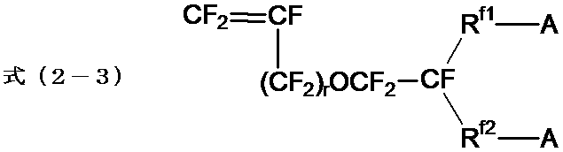
- a compound represented by the formula (2-1), a compound represented by the formula (2-2), or a compound represented by the formula (2-3) is preferable.
- R f1 is a perfluoroalkylene group which may contain an oxygen atom between carbon atoms.
- the number of carbon atoms in the perfluoroalkylene group is preferably 1 or more, more preferably 2 or more, preferably 20 or less, and more preferably 10 or less.
- R f2 is a single bond or a perfluoroalkylene group which may contain an oxygen atom between carbon atoms.
- the number of carbon atoms in the perfluoroalkylene group is preferably 1 or more, more preferably 2 or more, preferably 20 or less, and more preferably 10 or less.
- r is 0 or 1.
- R f2 in the formula is a single bond or a perfluoroalkylene group which may contain an oxygen atom between carbon atoms.
- the definition of A in the formula is as described above.
- w is an integer of 1 to 8
- x is an integer of 1 to 5.
- CF 2 CFCF—O— (CF 2 ) w —SO 2 F CF 2 CFCF—O—CF 2 CF (CF 3 ) —O— (CF 2 ) w —SO 2 F CF 2 CF- [O—CF 2 CF (CF 3 )] x —SO 2 F
- w is an integer of 1 to 8.
- R f3 is a linear perfluoroalkylene group having 1 to 6 carbon atoms
- R f4 is a straight bond having 1 to 6 carbon atoms which may contain an oxygen atom between a single bond or a carbon atom. It is a chain perfluoroalkylene group.
- the fluorinated monomer (S ′) one type may be used alone, or two or more types may be used in combination.
- another monomer may be used in addition to the fluorinated olefin and the fluorinated monomer (S ′).
- examples of other monomers include those exemplified above.
- the content of the unit based on another monomer is preferably 30% by mass or less based on all units in the fluoropolymer (S ′) from the viewpoint of maintaining ion exchange performance.
- the pellet of the present invention contains a fluoropolymer having a group that can be converted into an ion exchange group (fluoropolymer (I ′)), and comprises an ion exchange group of the fluoropolymer (I ′).
- the ion exchange capacity of the fluorine-containing polymer (fluorine-containing polymer (I)) is 1.1 meq / g resin or more and the light transmittance is 30 to 60% when the group which can be converted into the ion-exchange group is converted.
- One of the causes of the variation in the electrolytic voltage is non-uniformity of the thickness of the ion exchange membrane.
- Such non-uniformity of the thickness of the ion-exchange membrane is because, when a film-like ion-exchange membrane is produced using pellets of a fluoropolymer, the pellets are stuck to each other, and the pressure fluctuation increases during film formation. It is thought to occur in. In addition, the sticking between the pellets becomes remarkable when a fluoropolymer having a high ion exchange capacity is used as a raw material, when a group that can be converted into an ion exchange group can be converted into an ion exchange group.
- the surface of the present pellet having a light transmittance within the above range is roughened. Therefore, it is considered that the contact area between the pellets is reduced, and the sticking between the pellets can be suppressed. As a result, pressure fluctuations during film formation were suppressed, and as a result, an ion exchange membrane having excellent uniformity in film thickness was obtained.As a result, it was possible to suppress variations in electrolysis voltage when the ion exchange membrane was applied to an electrolytic device. Conceivable.
- the light transmittance of the pellets is 30 to 60%, and is preferably 30 to 50%, particularly preferably 30 to 40%, from the viewpoint of more excellent stability of the electrolytic voltage.
- the light transmittance of the pellet means a visible light transmittance (measurement wavelength: 400 to 700 nm) measured using a luminosity transmittance meter (Model 304 or a device equivalent thereto, manufactured by Asahi Spectroscopy).
- the specific measuring method is as follows.
- the luminosity transmittance meter is adjusted so that the visible light transmittance becomes 100% when a sample holder described below is not placed on the sample stage of the luminosity transmittance meter.
- a sample holder having a hole of a predetermined size for example, a rectangular hole having a length of 2 to 3 mm and a width of 2 to 3 mm) into which the pellet is to be inserted is set on the sample table, and the pellet is inserted into the hole of the sample holder.
- the light intensity is adjusted so that the visible light transmittance before fitting is 25%.
- a pellet having the same size as the hole of the sample holder is fitted into the hole of the sample holder, and the visible light transmittance is measured.
- the measurement of the visible light transmittance of the pellet is performed at a plurality of locations on one pellet, and the arithmetic average value is obtained.
- the pellet is fitted into the hole of the sample holder so that the side of the pellet is irradiated with light, and the pellet is rotated by 90 degrees in the circumferential direction so that 3 pellets per pellet.
- the visible light transmittance of the portion is measured, and the arithmetic average value thereof is obtained.
- the value of the visible light transmittance of the pellet was calculated when the visible light transmittance (25%) before fitting the pellet into the hole of the sample holder was converted to 100% (that is, the measured visible light transmittance of the pellet).
- the light transmittance is quadrupled), and this is defined as the light transmittance (%) of the pellet.
- the fluoropolymer (I ′) contained in the present pellets is the same as the fluoropolymer (I ′) used in the above-described production method, and has the same preferred embodiment such as an ion exchange capacity.
- the shape, size, surface state, application, and the like of the present pellets are the same as those of the pellets obtained by the above-described manufacturing method.
- the present pellets are preferably produced by the above-mentioned production method, since it is easy to keep the light transmittance within the above range.
- the ion exchange membrane of the present invention (hereinafter, also referred to as the present ion exchange membrane) is formed using the above-described present pellets.
- a precursor membrane containing a fluoropolymer having a group that can be converted into the above ion exchange group (fluoropolymer (I ′)) was formed using the pellet.
- Precursor film manufacturing method As a method for producing the precursor film, an extrusion method is exemplified. Specifically, the pellets are supplied to a known melt extruder for producing a film, and the melt of the pellets is extruded from a nozzle (for example, a T-die) of the melt extruder, and formed into a film. This is a method for obtaining a precursor film.
- the melting temperature of the present pellets is preferably from 150 to 350 ° C., particularly preferably from 200 to 300 ° C.
- a reinforcing material may be embedded in the precursor film.
- the reinforcing material can be embedded in the precursor film by a known method. For example, when forming an ion-exchange membrane having a multilayer structure, a method in which a reinforcing material is sandwiched between precursor films may be used.
- the reinforcing material can be embedded in the precursor film by a method of coating the melt of the present pellet on both surfaces of the reinforcing material.
- the reinforcing material examples include a reinforcing cloth (preferably a woven cloth), a fibril, and a porous body.
- the reinforcing cloth is preferable.
- the reinforcing cloth is composed of a warp and a weft, and it is preferable that the warp and the weft are orthogonal to each other.
- the reinforcing cloth preferably comprises a reinforcing yarn and a sacrificial yarn.
- the reinforcing yarn is a yarn made of a material that does not elute in the alkaline aqueous solution.
- the reinforcing yarn at least one type of reinforcing yarn selected from the group consisting of polytetrafluoroethylene, polyphenylene sulfide, nylon and polypropylene is preferable.
- the sacrificial yarn may be a monofilament composed of one filament or a multifilament composed of two or more filaments.
- the present ion exchange membrane containing the fluoropolymer (I) is obtained by converting a group that can be converted into an ion exchange group of the fluoropolymer (I ′) contained in the precursor membrane into an ion exchange group.
- a method of converting a group that can be converted into an ion exchange group in the precursor membrane into an ion exchange group a method of subjecting the precursor membrane to a treatment such as a hydrolysis treatment or an acid-formation treatment may be mentioned. Among them, a method in which the precursor film is brought into contact with an alkaline aqueous solution is preferable.
- the method of bringing the precursor film into contact with the alkaline aqueous solution include a method of dipping the precursor film in the alkaline aqueous solution and a method of spray-coating the surface of the precursor film with the alkaline aqueous solution.
- the temperature of the alkaline aqueous solution is preferably from 30 ° C. to less than 100 ° C. from the viewpoint of the productivity of the ion exchange membrane, and the contact time between the precursor membrane and the alkaline aqueous solution is preferably from 3 to 300 minutes.
- the alkaline aqueous solution preferably contains an alkali metal hydroxide, a water-soluble organic solvent and water.
- the alkali metal hydroxide include sodium hydroxide and potassium hydroxide, and potassium hydroxide is preferable.
- the alkali metal hydroxides may be used alone or in combination of two or more.
- a water-soluble organic solvent is an organic solvent that easily dissolves in water. Specifically, an organic solvent having a solubility in water of 1,000 ml (20 ° C.) of 0.1 g or more is preferable. More than 0.5 g of organic solvent is more preferred.
- the water-soluble organic solvent preferably contains at least one selected from the group consisting of aprotic organic solvents, alcohols and amino alcohols, and more preferably contains an aprotic organic solvent.
- the water-soluble organic solvent may be used alone or in combination of two or more.
- aprotic organic solvent examples include dimethylsulfoxide, N, N-dimethylformamide, N, N-dimethylacetamide, N-methyl-2-pyrrolidone, and N-ethyl-2-pyrrolidone.
- alcohols include methanol, ethanol, isopropanol, butanol, methoxyethoxyethanol, butoxyethanol, butyl carbitol, hexyloxyethanol, octanol, 1-methoxy-2-propanol, and ethylene glycol.
- amino alcohols include ethanolamine, N-methylethanolamine, N-ethylethanolamine, 1-amino-2-propanol, 1-amino-3-propanol, 2-aminoethoxyethanol, and 2-aminothiol. Ethoxyethanol and 2-amino-2-methyl-1-propanol are mentioned.
- the content of the alkali metal hydroxide is preferably 1 to 60% by mass in the alkaline aqueous solution.
- the content of the water-soluble organic solvent is preferably from 1 to 60% by mass in the alkaline aqueous solution.
- a treatment for removing the alkaline aqueous solution may be performed.
- a method of removing the alkaline aqueous solution for example, a method of washing the present ion exchange membrane in contact with the alkaline aqueous solution is exemplified.
- a treatment for drying the obtained ion exchange membrane may be performed.
- heat treatment is preferable, and the heating temperature at that time is preferably 50 to 160 ° C. The heating time is preferably from 0.1 to 24 hours.
- the present ion exchange membrane After converting a group that can be converted into an ion exchange group in the precursor membrane into an ion exchange group, the present ion exchange membrane is brought into contact with an aqueous solution containing potassium ions, sodium ions, or hydrogen ions, and a counter ion (cation) ) May be replaced.
- a counter ion (cation) By substituting the cation of the ion exchange group with the same cation as the cation present in the alkaline water, the cation can be subjected to alkaline water electrolysis in an environment where the substituted cation exists, and the dimensional stability of the present ion exchange membrane is reduced. improves.
- a hydrophilic layer may be formed on the surface of the precursor membrane or the present ion exchange membrane.
- the hydrophilic layer may be formed on at least one of the surfaces of the precursor membrane and the present ion exchange membrane.
- Specific examples of the hydrophilic layer include an inorganic particle layer containing inorganic particles.
- the inorganic particles preferably have excellent corrosion resistance to acids or alkalis and have hydrophilicity.
- at least one selected from the group consisting of oxides, nitrides and carbides of the Group 4 elements or Group 14 elements is preferable, and at least one selected from the group consisting of SiO 2 , SiC, ZrO 2 and ZrC is preferred. Is more preferable, and ZrO 2 is particularly preferable.
- the hydrophilizing layer may include a binder.
- a binder a known binder used for a known hydrophilizing layer (gas release layer) can be employed, and examples thereof include methylcellulose and a fluoropolymer having a sulfonic acid group.
- the method for forming the hydrophilic layer there is a method in which a solution containing inorganic particles and a binder is applied to the precursor membrane or the present ion exchange membrane.
- the ion exchange membrane may have a single layer or a multilayer structure.
- the ion exchange membrane having a multilayer structure can be produced, for example, using a precursor membrane obtained by laminating a plurality of layers of a fluoropolymer having a group that can be converted into an ion exchange group by a coextrusion method.
- the thickness of the present ion exchange membrane is preferably 30 ⁇ m or more, more preferably 40 ⁇ m or more, from the viewpoint of maintaining a constant strength, and is preferably 500 ⁇ m or less, more preferably 300 ⁇ m or less, and 180 ⁇ m from the viewpoint of increasing current efficiency and voltage efficiency. The following are more preferred.
- the fluorine-containing polymer (I) is a fluorine-containing polymer obtained by converting a group that can be converted into an ion-exchange group of the fluorine-containing polymer (I ′) contained in the precursor membrane into an ion-exchange group.
- the fluorine-containing polymer (I) is a fluorine-containing polymer having a carboxylic acid type functional group (hereinafter, also referred to as a fluorine-containing polymer (C)) or a sulfonic acid type functional group because the effects of the present invention can be more exhibited. (Hereinafter, also referred to as a fluorine-containing polymer (S)) is preferable.
- each fluoropolymer will be described in detail.
- the fluorine-containing polymer (C) is preferably obtained by converting a group that can be converted into a carboxylic acid type functional group of the above-mentioned fluorine-containing polymer (C ′) into a carboxylic acid group.
- the fluorine-containing polymer (C) preferably contains units based on a fluorine-containing olefin and units based on a monomer having a carboxylic acid type functional group and a fluorine atom. Examples of the fluorinated olefin include those exemplified above.
- the unit based on the fluorine-containing olefin may be contained alone or in combination of two or more.
- a unit represented by the following formula (1C) is preferable.
- X, X ', p, q, r, s, t and u are the same as in the above formula (1).
- the fluorinated polymer (C) may contain units based on other monomers other than units based on a fluorinated olefin and units based on a monomer having a carboxylic acid type functional group and a fluorine atom. Specific examples of other monomers include those exemplified above.
- the content of the unit based on another monomer is preferably 30% by mass or less based on all units in the fluoropolymer (C) from the viewpoint of maintaining ion exchange performance.
- the fluorine-containing polymer (S) is preferably obtained by converting a group that can be converted into a sulfonic acid type functional group of the above-mentioned fluorine-containing polymer (S ′) into a sulfonic acid group.
- the fluorine-containing polymer (S) preferably contains units based on a fluorine-containing olefin and units based on a monomer having a sulfonic acid type functional group and a fluorine atom. Examples of the fluorinated olefin include those exemplified above.
- the unit based on the fluorine-containing olefin may be contained alone or in combination of two or more.
- M S is a hydrogen atom, an alkali metal or a quaternary ammonium cation.
- the unit represented by the formula (2S) includes a unit represented by the formula (2S-1), a unit represented by the formula (2S-2), and a unit represented by the formula (2S-3). preferable.
- Formula (2S-1) [CF 2 —CF (—O—R f1 —SO 3 M S )] —
- R f1 , R f2 and r are the same as those in the above formulas (2-1) to (2-3).
- M S is a hydrogen atom, an alkali metal or a quaternary ammonium cation.
- w is an integer of 1 to 8
- x is an integer of 1 to 5.
- M S in the formula is as described above. -[CF 2 -CF (-O- (CF 2 ) w -SO 3 M S )]- -[CF 2 -CF (-O-CF 2 CF (CF 3 ) -O- (CF 2 ) w -SO 3 M S )]- -[CF 2 -CF (-(O-CF 2 CF (CF 3 )) x -SO 3 M S )]-
- w is an integer of 1 to 8.
- M S in the formula is as described above. -[CF 2 -CF (-(CF 2 ) w -SO 3 M S )]- -[CF 2 -CF (-CF 2 -O- (CF 2 ) w -SO 3 M S )]-
- the unit represented by the formula (2S-3) is preferably a unit represented by the formula (2S-3-1). Defining M S in the formula is as described above.
- Units based on a monomer having a sulfonic acid type functional group and a fluorine atom may be used alone or in combination of two or more.
- the fluoropolymer (S) may contain units based on other monomers other than the units based on the fluoroolefin and the units based on the monomer having a sulfonic acid type functional group and a fluorine atom. Specific examples of other monomers include those exemplified above.
- the content of the unit based on another monomer is preferably 30% by mass or less based on all units in the fluoropolymer (S) from the viewpoint of maintaining ion exchange performance.
- ion exchange membrane Specific examples of applications of the ion exchange membrane include various types of battery applications such as solid polymer fuel cells, direct methanol fuel cells, redox flow batteries, air batteries, solid polymer water electrolysis, alkaline water electrolysis, and ozone. Examples include water electrolysis, salt electrolysis, organic electrolysis, and various electrolysis devices such as chlorides and oxides. In addition to the above-mentioned applications, it can be used as a separator or a solid electrode in various types of electrochemical cells for selective cation transport at a binding portion of the cells. In addition to electrochemical-related applications, it can be used for various gas sensors, biosensors, light-emitting devices, optical devices, organic matter sensors, solubilization of carbon nanotubes, actuators, catalysts and the like as sensor applications.
- battery applications such as solid polymer fuel cells, direct methanol fuel cells, redox flow batteries, air batteries, solid polymer water electrolysis, alkaline water electrolysis, and ozone. Examples include water electrolysis, salt electrolysis
- the visible light transmittance (measurement wavelength: 400 to 700 nm) without a sample holder described later on the sample stage of a luminous transmittance meter (TLV-304-BP, manufactured by Asahi Spectroscopy) is 100%. Then, the luminosity transmittance meter was adjusted. Next, a sample holder (thickness 0.7 mm) having a rectangular hole (hole size: 2 to 3 mm in length ⁇ 2 to 3 mm in width) into which the pellet is to be inserted is set on the sample table, and the hole in the sample holder is set. The light intensity was adjusted so that the visible light transmittance before fitting the pellets into the glass was 25%.
- a pellet (cylindrical shape having a diameter of 2 to 3 mm and a length of 2 to 3 mm) having substantially the same size as the hole of the sample holder is fitted into the hole of the sample holder so that the side of the pellet is irradiated with light, and visible light is emitted.
- the transmittance was measured.
- the measurement of the visible light transmittance of the pellet was performed by rotating the pellet by 90 degrees in the circumferential direction, measuring the light transmittance at three places with respect to one pellet, and calculating the arithmetic average value thereof. .
- the value of the visible light transmittance of the pellet was calculated when the visible light transmittance (25%) before fitting the pellet into the hole of the sample holder was converted to 100% (that is, the measured visible light transmittance of the pellet).
- the light transmittance was quadrupled), and this was defined as the light transmittance (%) of the pellet.
- the ion exchange membrane was placed in a test electrolytic cell having an effective energization area of 1.5 dm 2 (electrolytic surface size: 150 mm long ⁇ 100 mm wide).
- electrolytic cell a punched metal of titanium (short diameter 4 mm, long diameter 8 mm) coated with a solid solution of ruthenium oxide, iridium oxide and titanium oxide is used as a cathode, and a punched metal made of SUS304 (short diameter 5 mm, A long-diameter (10 mm long) electrodeposited with Raney nickel containing ruthenium was used and placed so that the electrode and the ion exchange membrane were in direct contact and no gap was formed.
- the ion exchange capacity is obtained by treating the fluoropolymers (S′-1) to (S′-3) and (C′-1) according to the following procedure. Indicates capacity. First, a fluorinated polymer having a group that can be converted into an ion-exchange group subjected to vacuum heat treatment at 240 ° C.
- Example 1 The fluoropolymer (S'-1) was supplied to a melt extruder for pellet production to obtain a melt of the fluoropolymer (S'-1).
- the obtained melt was extruded from a die heated to 190 ° C., and cooled to obtain a strand (diameter: 3.0 mm). Subsequently, the strand was cut into a length of 3.0 mm to obtain a fluoropolymer (S′-1) pellet.
- the above-described various measurements were performed using the obtained pellets.
- the fluoropolymer (S′-1) pellets are supplied to a melt extruder for film production, and the pellets are melted at 260 ° C.
- the group which can be converted into a group was hydrolyzed to convert into a K-type sulfonic acid type functional group, and then washed with water.
- it was immersed in an aqueous solution of sodium hydroxide to convert the terminal group from K type to Na type, and then dried to obtain an ion exchange membrane having a thickness of 30 ⁇ m.
- the various measurements described above were performed using the obtained ion exchange membrane.
- Examples 2 to 8, Comparative Examples 1 to 4 A pellet and an ion exchange membrane were prepared in the same manner as in Example 1 except that at least one of the type of the fluoropolymer for pellet production and the die temperature during pellet production was changed as shown in Table 1, and various measurements were performed. Carried out. Table 1 shows the results of various measurements.
- a fluorine-containing compound having a group that can be converted to an ion-exchange group such that the ion-exchange capacity of the group that can be converted to an ion-exchange group is 1.1 meq / g resin or more.
- FIG. 1 is a photographic image of the appearance of the fluoropolymer (S′-1) pellets of Example 1. Using a microscope (manufactured by Keyence Corporation: VHX-900), an external appearance photograph of the pellet was taken at a magnification of 30 times. As shown in FIG. 1, the shape of the pellet is substantially cylindrical, and a groove is formed on a side surface. The direction in which the groove formed on the side surface extends is the flow direction of the strand during pellet production.
- the entire contents of the specification, claims, drawings, and abstract of Japanese Patent Application No. 2018-172344 filed on Sep. 14, 2018 are cited here, and are hereby incorporated by reference. , Is to take in.
Landscapes
- Chemical & Material Sciences (AREA)
- Organic Chemistry (AREA)
- Chemical Kinetics & Catalysis (AREA)
- Engineering & Computer Science (AREA)
- Medicinal Chemistry (AREA)
- Polymers & Plastics (AREA)
- Health & Medical Sciences (AREA)
- Mechanical Engineering (AREA)
- Materials Engineering (AREA)
- Manufacturing & Machinery (AREA)
- Inorganic Chemistry (AREA)
- Electrochemistry (AREA)
- Metallurgy (AREA)
- General Chemical & Material Sciences (AREA)
- Physics & Mathematics (AREA)
- Thermal Sciences (AREA)
- Manufacture Of Macromolecular Shaped Articles (AREA)
- Processing And Handling Of Plastics And Other Materials For Molding In General (AREA)
- Processes Of Treating Macromolecular Substances (AREA)
- Addition Polymer Or Copolymer, Post-Treatments, Or Chemical Modifications (AREA)
Abstract
電解電圧の安定性に優れたイオン交換膜を形成できるペレットの製造方法、ペレット及びイオン交換膜の提供。 本発明のペレットの製造方法は、イオン交換基に変換できる基を有する含フッ素ポリマーを含む溶融物を溶融押出機のダイスから押し出して、上記含フッ素ポリマーを含むストランドを得た後、上記ストランドを切断して上記含フッ素ポリマーを含むペレットを得る、ペレットの製造方法であって、上記含フッ素ポリマーを含む溶融物を上記ダイスから押し出す際の上記ダイスの温度が、200℃未満であり、上記含フッ素ポリマーのイオン交換基に変換できる基をイオン交換基に変換した際の含フッ素ポリマーのイオン交換容量が、1.1meq/g樹脂以上である。
Description
本発明は、ペレットの製造方法、ペレット及びイオン交換膜に関する。
各種電池、電解プロセス及びイオン等の分離プロセスにおいて、イオン交換基を有する含フッ素ポリマーを含むイオン交換膜が使用されている。
含フッ素ポリマーを含むイオン交換膜の製造方法としては、イオン交換基又はイオン交換基に変換できる基を有する含フッ素ポリマーのペレットを原料として用いる方法が知られている(特許文献1参照)。
含フッ素ポリマーを含むイオン交換膜の製造方法としては、イオン交換基又はイオン交換基に変換できる基を有する含フッ素ポリマーのペレットを原料として用いる方法が知られている(特許文献1参照)。
近年、イオン交換膜を含む電解装置について、生産効率の点から、電解電圧の安定性に優れること(電解電圧の変動幅が小さいこと)が求められている。本発明者が、特許文献1に記載の含フッ素ポリマーのペレットを用いて得られたイオン交換膜を電解装置に適用したところ、電解電圧の変動幅が大きく、改善の余地があることがわかった。
本発明は、上記課題に鑑みて、電解電圧の安定性に優れたイオン交換膜を得ることができるペレットの製造方法、ペレット及びイオン交換膜の提供を課題とする。
本発明者は、上記課題を達成するべく鋭意検討した結果、イオン交換基に変換できる基を有する含フッ素ポリマーを用いて含フッ素ポリマーを含むペレットを製造する場合、イオン交換基に変換できる基をイオン交換基に変換した際のイオン交換容量が1.1ミリ当量/グラム乾燥樹脂(以下、meq/g樹脂ともいう。)以上となるようにし、かつ、含フッ素ポリマーの溶融物を溶融混練機のダイスから押し出す際のダイスの温度が200℃未満にせしめることにより、目的とする効果が得られることを見出し、本発明に至った。
本発明は、以下の態様を有するものである。
[1]イオン交換基に変換できる基を有する含フッ素ポリマーを含む溶融物を溶融押出機のダイスから押し出して、上記含フッ素ポリマーを含むストランドを得た後、上記ストランドを切断して上記含フッ素ポリマーを含むペレットを得るペレットの製造方法であって、
上記含フッ素ポリマーを含む溶融物を上記ダイスから押し出す際の上記ダイスの温度が、200℃未満であり、
上記含フッ素ポリマーのイオン交換基に変換できる基をイオン交換基に変換した際の含フッ素ポリマーのイオン交換容量が、1.1meq/g樹脂以上であることを特徴とする、ペレットの製造方法。
[2]上記ストランドを切断して、光線透過率が30~60%である含フッ素ポリマーを含むペレットを得る上記[1]の製造方法。
[3]上記含フッ素ポリマーのイオン交換基に変換できる基をイオン交換基に変換した際の含フッ素ポリマーのイオン交換容量が、2.00ミリ当量/グラム乾燥樹脂以下である上記[1]又は[2]の製造方法。
[4]上記イオン交換基に変換できる基が、カルボン酸型官能基に変換できる基又はスルホン酸型官能基に変換できる基である上記[1]~[3]のいずれかの製造方法。
[5]上記イオン交換基に変換できる基を有する含フッ素ポリマーが、含フッ素オレフィンと、下式(1)で表されるモノマーと、の共重合ポリマーである上記[1]~[4]のいずれかの製造方法。
式(1):CF2=CF-(O)p-(CF2)q-(CF2CFX)r-(O)s-(CF2)t-(CF2CFX’)u-A1
(X及びX’は、それぞれ独立して、フッ素原子又はトリフルオロメチル基である。A1は、カルボン酸型官能基に変換できる基である。pは0又は1の整数である。qは、0~12の整数である。rは、0~3の整数である。sは、0又は1の整数である。tは、0~12の整数である。uは、0~3の整数である。但し、1≦p+sであり、1≦r+uである。)
[6]上記イオン交換基に変換できる基を有する含フッ素ポリマーが、含フッ素オレフィンと、下式(2)で表されるモノマーと、の共重合ポリマーである上記[1]~[4]のいずれかの製造方法。
式(2):CF2=CF-L-(A)n
(Lは、酸素原子を含んでいてもよいn+1価のペルフルオロ炭化水素基である。nは、1又は2である。Aは、スルホン酸型官能基に変換できる基である。)
[7]上記式(2)で表されるモノマーが、式(2-1)で表される化合物、式(2-2)で表される化合物、又は式(2-3)で表される化合物である上記[6]の製造方法。
式(2-1):CF2=CF-O-Rf1-A
式(2-2):CF2=CF-Rf1-A
(Rf1は、炭素原子-炭素原子間に酸素原子を含んでいてもよいペルフルオロアルキレン基である。Rf2は、単結合又は炭素原子-炭素原子間に酸素原子を含んでいてもよいペルフルオロアルキレン基である。Aは、式2(B)において記載したとおりである。)
[8]イオン交換膜の製造に使用する上記[1]~[7]のいずれかの製造方法。
[9]イオン交換基に変換できる基を有する含フッ素ポリマーを含み、
上記含フッ素ポリマーのイオン交換基に変換できる基をイオン交換基に変換した際の含フッ素ポリマーのイオン交換容量が、1.1meq/g樹脂以上であり、
光線透過率が30~60%であることを特徴とするペレット。
[10]上記イオン交換基に変換できる基が、カルボン酸型官能基に変換できる基又はスルホン酸型官能基に変換できる基である上記[9]のペレット。
[11]イオン交換膜の製造に使用する上記[9]又は[10]のペレット。
[12]上記[9]~[11]のいずれかのペレットを用いて形成されるイオン交換膜。
[13]膜厚が、30~180μmである上記[13]のイオン交換膜。
[14]塩化アルカリ水溶液の電解に使用される上記[12]又は[13]のイオン交換膜。
[1]イオン交換基に変換できる基を有する含フッ素ポリマーを含む溶融物を溶融押出機のダイスから押し出して、上記含フッ素ポリマーを含むストランドを得た後、上記ストランドを切断して上記含フッ素ポリマーを含むペレットを得るペレットの製造方法であって、
上記含フッ素ポリマーを含む溶融物を上記ダイスから押し出す際の上記ダイスの温度が、200℃未満であり、
上記含フッ素ポリマーのイオン交換基に変換できる基をイオン交換基に変換した際の含フッ素ポリマーのイオン交換容量が、1.1meq/g樹脂以上であることを特徴とする、ペレットの製造方法。
[2]上記ストランドを切断して、光線透過率が30~60%である含フッ素ポリマーを含むペレットを得る上記[1]の製造方法。
[3]上記含フッ素ポリマーのイオン交換基に変換できる基をイオン交換基に変換した際の含フッ素ポリマーのイオン交換容量が、2.00ミリ当量/グラム乾燥樹脂以下である上記[1]又は[2]の製造方法。
[4]上記イオン交換基に変換できる基が、カルボン酸型官能基に変換できる基又はスルホン酸型官能基に変換できる基である上記[1]~[3]のいずれかの製造方法。
[5]上記イオン交換基に変換できる基を有する含フッ素ポリマーが、含フッ素オレフィンと、下式(1)で表されるモノマーと、の共重合ポリマーである上記[1]~[4]のいずれかの製造方法。
式(1):CF2=CF-(O)p-(CF2)q-(CF2CFX)r-(O)s-(CF2)t-(CF2CFX’)u-A1
(X及びX’は、それぞれ独立して、フッ素原子又はトリフルオロメチル基である。A1は、カルボン酸型官能基に変換できる基である。pは0又は1の整数である。qは、0~12の整数である。rは、0~3の整数である。sは、0又は1の整数である。tは、0~12の整数である。uは、0~3の整数である。但し、1≦p+sであり、1≦r+uである。)
[6]上記イオン交換基に変換できる基を有する含フッ素ポリマーが、含フッ素オレフィンと、下式(2)で表されるモノマーと、の共重合ポリマーである上記[1]~[4]のいずれかの製造方法。
式(2):CF2=CF-L-(A)n
(Lは、酸素原子を含んでいてもよいn+1価のペルフルオロ炭化水素基である。nは、1又は2である。Aは、スルホン酸型官能基に変換できる基である。)
[7]上記式(2)で表されるモノマーが、式(2-1)で表される化合物、式(2-2)で表される化合物、又は式(2-3)で表される化合物である上記[6]の製造方法。
式(2-1):CF2=CF-O-Rf1-A
式(2-2):CF2=CF-Rf1-A
[8]イオン交換膜の製造に使用する上記[1]~[7]のいずれかの製造方法。
[9]イオン交換基に変換できる基を有する含フッ素ポリマーを含み、
上記含フッ素ポリマーのイオン交換基に変換できる基をイオン交換基に変換した際の含フッ素ポリマーのイオン交換容量が、1.1meq/g樹脂以上であり、
光線透過率が30~60%であることを特徴とするペレット。
[10]上記イオン交換基に変換できる基が、カルボン酸型官能基に変換できる基又はスルホン酸型官能基に変換できる基である上記[9]のペレット。
[11]イオン交換膜の製造に使用する上記[9]又は[10]のペレット。
[12]上記[9]~[11]のいずれかのペレットを用いて形成されるイオン交換膜。
[13]膜厚が、30~180μmである上記[13]のイオン交換膜。
[14]塩化アルカリ水溶液の電解に使用される上記[12]又は[13]のイオン交換膜。
本発明によれば、イオン交換膜を形成するフィルム成形時の圧力変動が抑えられ、膜厚の均一性に優れたイオン交換膜が得られる結果、電解装置に適用した際に電解電圧のばらつきを抑制でき、電解電圧の安定性に優れたイオン交換膜を形成できるペレットの製造方法、ペレット、及びイオン交換膜が提供される。
本発明における用語の意味は以下の通りである。
「イオン交換基」とは、この基に含まれるイオンの少なくとも一部を、他のイオンに交換しうる基であり、例えば、下記のスルホン酸型官能基、カルボン酸型官能基が挙げられる。
「スルホン酸型官能基」とは、スルホン酸基(-SO3H)、又はスルホン酸塩基(-SO3M2。但し、M2はアルカリ金属又は第4級アンモニウムカチオンである。)を意味する。
「カルボン酸型官能基」とは、カルボン酸基(-COOH)、又はカルボン酸塩基(-COOM1。但し、M1はアルカリ金属又は第4級アンモニウムカチオンである。)を意味する。
「前駆体膜」とは、イオン交換基に変換できる基を有するポリマーを含む膜である。
「イオン交換基に変換できる基」とは、加水分解処理、酸型化処理、その他金属カチオンへの塩交換等の処理によって、イオン交換基に変換できる基を意味する。
「スルホン酸型官能基に変換できる基」とは、加水分解処理、酸型化処理等の処理によって、スルホン酸型官能基に変換できる基を意味する。
「カルボン酸型官能基に変換できる基」とは、加水分解処理、酸型化処理等の公知の処理によって、カルボン酸型官能基に変換できる基を意味する。
「ペルフルオロ炭化水素基」とは、水素原子の全てがフッ素原子で置換された炭化水素基を意味する。
「ペルフルオロ脂肪族炭化水素基」とは、水素原子の全てがフッ素原子で置換された脂肪族炭化水素基を意味する。
「イオン交換基」とは、この基に含まれるイオンの少なくとも一部を、他のイオンに交換しうる基であり、例えば、下記のスルホン酸型官能基、カルボン酸型官能基が挙げられる。
「スルホン酸型官能基」とは、スルホン酸基(-SO3H)、又はスルホン酸塩基(-SO3M2。但し、M2はアルカリ金属又は第4級アンモニウムカチオンである。)を意味する。
「カルボン酸型官能基」とは、カルボン酸基(-COOH)、又はカルボン酸塩基(-COOM1。但し、M1はアルカリ金属又は第4級アンモニウムカチオンである。)を意味する。
「前駆体膜」とは、イオン交換基に変換できる基を有するポリマーを含む膜である。
「イオン交換基に変換できる基」とは、加水分解処理、酸型化処理、その他金属カチオンへの塩交換等の処理によって、イオン交換基に変換できる基を意味する。
「スルホン酸型官能基に変換できる基」とは、加水分解処理、酸型化処理等の処理によって、スルホン酸型官能基に変換できる基を意味する。
「カルボン酸型官能基に変換できる基」とは、加水分解処理、酸型化処理等の公知の処理によって、カルボン酸型官能基に変換できる基を意味する。
「ペルフルオロ炭化水素基」とは、水素原子の全てがフッ素原子で置換された炭化水素基を意味する。
「ペルフルオロ脂肪族炭化水素基」とは、水素原子の全てがフッ素原子で置換された脂肪族炭化水素基を意味する。
ポリマーにおける「単位」は、モノマーが重合して形成された、該モノマー1分子に由来する原子団を意味する。単位は、重合反応によって直接形成された原子団であってもよく、重合反応によって得られたポリマーを処理して該原子団の一部が別の構造に変換された原子団であってもよい。
「補強材」は、イオン交換膜の強度を向上させるために用いられる材料を意味する。補強材としては、補強布に由来する材料が好ましい。
「補強布」は、イオン交換膜の強度を向上させるための補強材の原料として用いられる布を意味する。
「補強糸」は、補強布を構成する糸であり、イオン交換膜を含む装置の運転環境下で溶出しない糸である。「補強糸」としては、補強布をアルカリ性水溶液(例えば、濃度が32質量%の水酸化ナトリウム水溶液)に浸漬しても溶出しない材料からなる糸が好ましい。
「犠牲糸」は、補強布を構成する糸であり、イオン交換膜を含む装置の運転環境下でその少なくとも一部が溶出する糸である。「犠牲糸」としては、補強布をアルカリ性水溶液に浸漬したときに、アルカリ性水溶液に溶出する材料からなる糸が好ましい。
「~」を用いて表される数値範囲は、「~」の前後に記載される数値を下限値及び上限値として含む範囲を意味する。また、下限値および上限値の単位が同じ場合には、下限値についての単位を省略する場合がある。
「補強布」は、イオン交換膜の強度を向上させるための補強材の原料として用いられる布を意味する。
「補強糸」は、補強布を構成する糸であり、イオン交換膜を含む装置の運転環境下で溶出しない糸である。「補強糸」としては、補強布をアルカリ性水溶液(例えば、濃度が32質量%の水酸化ナトリウム水溶液)に浸漬しても溶出しない材料からなる糸が好ましい。
「犠牲糸」は、補強布を構成する糸であり、イオン交換膜を含む装置の運転環境下でその少なくとも一部が溶出する糸である。「犠牲糸」としては、補強布をアルカリ性水溶液に浸漬したときに、アルカリ性水溶液に溶出する材料からなる糸が好ましい。
「~」を用いて表される数値範囲は、「~」の前後に記載される数値を下限値及び上限値として含む範囲を意味する。また、下限値および上限値の単位が同じ場合には、下限値についての単位を省略する場合がある。
[ペレットの製造方法]
本発明のペレットの製造方法(以下、本製造方法ともいう。)は、イオン交換基に変換できる基を有する含フッ素ポリマー(以下、含フッ素ポリマー(I’)ともいう。)を含む溶融物を溶融押出機のダイスから押し出して、上記含フッ素ポリマー(I’)を含むストランドを得た後、上記ストランドを切断して上記含フッ素ポリマー(I’)を含むペレットを得るペレットの製造方法である。
また、本製造方法において、上記含フッ素ポリマー(I’)を含む溶融物を上記ダイスから押し出す際の上記ダイスの温度は、200℃未満である。
また、本製造方法において、上記含フッ素ポリマー(I’)のイオン交換基に変換できる基をイオン交換基に変換した際の含フッ素ポリマー(以下、含フッ素ポリマー(I)ともいう。)のイオン交換容量が、1.1meq/g樹脂以上である。
本発明のペレットの製造方法(以下、本製造方法ともいう。)は、イオン交換基に変換できる基を有する含フッ素ポリマー(以下、含フッ素ポリマー(I’)ともいう。)を含む溶融物を溶融押出機のダイスから押し出して、上記含フッ素ポリマー(I’)を含むストランドを得た後、上記ストランドを切断して上記含フッ素ポリマー(I’)を含むペレットを得るペレットの製造方法である。
また、本製造方法において、上記含フッ素ポリマー(I’)を含む溶融物を上記ダイスから押し出す際の上記ダイスの温度は、200℃未満である。
また、本製造方法において、上記含フッ素ポリマー(I’)のイオン交換基に変換できる基をイオン交換基に変換した際の含フッ素ポリマー(以下、含フッ素ポリマー(I)ともいう。)のイオン交換容量が、1.1meq/g樹脂以上である。
本製造方法によれば、電解電圧の安定性に優れたイオン交換膜を形成できるペレットが得られる。この理由の詳細は明らかになっていないが、以下の理由によると推測される。 電解電圧のばらつきの発生原因の1つとして、イオン交換膜の膜厚の不均一性が挙げられる。このようなイオン交換膜の膜厚の不均一性は、含フッ素ポリマー(I’)を含むペレットを用いてフィルム状のイオン交換膜を製造する際に、ペレット同士がくっついて、フィルム成形時に圧力変動が大きくなるために発生すると考えられる。また、ペレット同士のくっつきは、イオン交換基に変換できる基をイオン交換基に変換した際にイオン交換容量の高い含フッ素ポリマーになり得る、含フッ素ポリマーを原料とした場合に顕著になる。
この問題に対して、含フッ素ポリマー(I’)を含む溶融物をダイスから押し出す際のダイス温度を低くすれば、メルトフラクチャーの発生によってストランド(ペレット)の表面が粗面化して(具体的には、ペレット表面に複数の溝が形成される)、ペレット同士のくっつきを抑制できることを見出した。これにより、フィルム成形時の圧力変動が抑えられて、膜厚の均一性に優れたイオン交換膜が得られた結果、イオン交換膜を電解装置に適用した際に電解電圧のばらつきを抑制できたと考えられる。
以下において、本製造方法の一例を示す。
まず、イオン交換基に変換できる基を有する含フッ素ポリマーを溶融押出機に供給して、含フッ素ポリマーの溶融物を得る。
溶融押出機は、公知の装置を使用でき、具体的には、単軸押出機、二軸押出機、タンデム押出機が挙げられる。
含フッ素ポリマー(I’)の溶融温度は、150~350℃が好ましく、200~300℃が特に好ましい。
まず、イオン交換基に変換できる基を有する含フッ素ポリマーを溶融押出機に供給して、含フッ素ポリマーの溶融物を得る。
溶融押出機は、公知の装置を使用でき、具体的には、単軸押出機、二軸押出機、タンデム押出機が挙げられる。
含フッ素ポリマー(I’)の溶融温度は、150~350℃が好ましく、200~300℃が特に好ましい。
次に、含フッ素ポリマー(I’)の溶融物を溶融押出機の先端にあるダイスから押し出して、これを冷却して含フッ素ポリマー(I’)を含むストランドを得た後、ストランドを所定サイズに切断する。このようにして、含フッ素ポリマー(I’)を含むペレットが得られる。
本製造方法の一例では、ペレットの切断処理方法としていわゆるストランドカット法を用いる場合を示したが、水中カット法、ホットカット法等を用いてもよい。
本製造方法の一例では、ペレットの切断処理方法としていわゆるストランドカット法を用いる場合を示したが、水中カット法、ホットカット法等を用いてもよい。
ここで、含フッ素ポリマー(I’)を含む溶融物を上記ダイスから押し出す際の上記ダイスの温度(以下、単に、ダイス温度ともいう。)は、200℃未満であり、電解電圧の安定性がより優れる点で、190℃以下が好ましく、170℃以下がより好ましく、150℃以下が特に好ましく、145℃以下が最も好ましい。
ダイス温度は、含フッ素ポリマー(I’)の溶融物のダイスからの押し出しが容易になる点から、140℃以上が好ましく、142℃以上がより好ましい。
特に、含フッ素ポリマー(I’)のイオン交換基に変換できる基をイオン交換基に変換した際の含フッ素ポリマー(すなわち、含フッ素ポリマー(I))のイオン交換容量が、1.2meq/g樹脂以上の場合、電解電圧の安定性により優れる点、及び、電解効率により優れる点から、ダイス温度は、140℃以上200℃未満が好ましく、140~150℃がより好ましく、140~145℃が特に好ましい。
ダイス温度は、含フッ素ポリマー(I’)の溶融物のダイスからの押し出しが容易になる点から、140℃以上が好ましく、142℃以上がより好ましい。
特に、含フッ素ポリマー(I’)のイオン交換基に変換できる基をイオン交換基に変換した際の含フッ素ポリマー(すなわち、含フッ素ポリマー(I))のイオン交換容量が、1.2meq/g樹脂以上の場合、電解電圧の安定性により優れる点、及び、電解効率により優れる点から、ダイス温度は、140℃以上200℃未満が好ましく、140~150℃がより好ましく、140~145℃が特に好ましい。
本製造方法により得られるペレットの形状は、特に限定されず、例えば、球状(楕円体状も含む)、柱状(例えば、円柱状)等のいずれの形状であってもよい。
本製造方法により得られるペレットのサイズは、特に限定されないが、例えばペレットが円柱状である場合、直径が2~3mmであり、長さ2~3mmであるのが好ましい。
本製造方法により得られるペレットのサイズは、特に限定されないが、例えばペレットが円柱状である場合、直径が2~3mmであり、長さ2~3mmであるのが好ましい。
本製造方法により得られるペレット(ストランド)の表面は、複数の溝が形成されているのが好ましい。これにより、ペレット同士のくっつきを抑制できる。
ペレットの表面の形成された溝は、ペレットの表面全体に形成されていてもよいが、通常、ペレットの側面(ストランドの切断面以外の面)のみに形成されているのが好ましい。
ペレットの表面に形成された溝は、主にペレットの切断面と交差する方向(ストランドの流れ方向)に沿って形成されていることが好ましい。
ペレットの表面の形成された溝は、ペレットの表面全体に形成されていてもよいが、通常、ペレットの側面(ストランドの切断面以外の面)のみに形成されているのが好ましい。
ペレットの表面に形成された溝は、主にペレットの切断面と交差する方向(ストランドの流れ方向)に沿って形成されていることが好ましい。
本製造方法において、ストランドの切断後、ペレットの表面を粗面化する粗面化処理を実施してもよい。これにより、ペレットの表面がより粗面化されて、ペレット同士のくっつきをより抑制できるため、電解電圧の安定性により優れたイオン交換膜が得られる。
粗面化処理の方法の具体例としては、混合機(例えば、Vブレンダー)を用いてペレットを攪拌する方法が挙げられる。
粗面化処理の方法の具体例としては、混合機(例えば、Vブレンダー)を用いてペレットを攪拌する方法が挙げられる。
本製造方法により得られるペレットは、イオン交換膜の製造に使用するのが好ましい。イオン交換膜の用途の具体例については、後述する。
〔含フッ素ポリマー(I’)〕
本製造方法において使用する含フッ素ポリマー(I’)は、イオン交換基に変換できる基を有する含フッ素ポリマーである。イオン交換基に変換できる基としては、好ましくは、カルボン酸型官能基に変換できる基、又はスルホン酸型官能基に変換できる基が挙げられる。
本製造方法において使用する含フッ素ポリマー(I’)は、イオン交換基に変換できる基を有する含フッ素ポリマーである。イオン交換基に変換できる基としては、好ましくは、カルボン酸型官能基に変換できる基、又はスルホン酸型官能基に変換できる基が挙げられる。
含フッ素ポリマー(I’)のイオン交換基に変換できる基をイオン交換基に変換した際の含フッ素ポリマー(すなわち、含フッ素ポリマー(I))のイオン交換容量は、1.1meq/g樹脂以上であり、装置の電解電圧を低減できる点から、1.20meq/g樹脂以上が特に好ましく、イオン交換膜の強度がより優れる点から、2.00meq/g樹脂以下が好ましく、1.90meq/g樹脂以下が特に好ましい。
ここで、イオン交換容量を測定するための含フッ素ポリマー(I)は、次のようにして得られる。まず、240℃、-0.1MPaGで16時間真空熱処理した含フッ素ポリマー(I’)を、ジメチルスルホキシド/水酸化カリウム/水=30/5.5/64.5(質量比)の溶液に95℃で30分間浸漬し、含フッ素ポリマー(I’)中のイオン交換基に変換できる基を加水分解して、K型のイオン交換基に変換した後、水洗する。その後、水酸化ナトリウム水溶液に浸漬し、末端基をK型からNa型に変換して、イオン交換容量を測定するための含フッ素ポリマー(I)を得る。
なお、このようにして得られた含フッ素ポリマー(I)のイオン交換容量の測定方法は、後述の実施例欄に記載の通りである。
ここで、イオン交換容量を測定するための含フッ素ポリマー(I)は、次のようにして得られる。まず、240℃、-0.1MPaGで16時間真空熱処理した含フッ素ポリマー(I’)を、ジメチルスルホキシド/水酸化カリウム/水=30/5.5/64.5(質量比)の溶液に95℃で30分間浸漬し、含フッ素ポリマー(I’)中のイオン交換基に変換できる基を加水分解して、K型のイオン交換基に変換した後、水洗する。その後、水酸化ナトリウム水溶液に浸漬し、末端基をK型からNa型に変換して、イオン交換容量を測定するための含フッ素ポリマー(I)を得る。
なお、このようにして得られた含フッ素ポリマー(I)のイオン交換容量の測定方法は、後述の実施例欄に記載の通りである。
含フッ素ポリマー(I’)は、1種を単独で用いてもよく、2種以上を組み合わせて用いてもよい。
含フッ素ポリマー(I’)は、本発明の効果がより発揮できる点から、カルボン酸型官能基に変換できる基を有する含フッ素ポリマー(以下、含フッ素ポリマー(C’)ともいう。)、又は、スルホン酸型官能基に変換できる基を有する含フッ素ポリマー(以下、含フッ素ポリマー(S’)ともいう。)が好ましい。
以下、各含フッ素ポリマーについて詳述する。
含フッ素ポリマー(I’)は、本発明の効果がより発揮できる点から、カルボン酸型官能基に変換できる基を有する含フッ素ポリマー(以下、含フッ素ポリマー(C’)ともいう。)、又は、スルホン酸型官能基に変換できる基を有する含フッ素ポリマー(以下、含フッ素ポリマー(S’)ともいう。)が好ましい。
以下、各含フッ素ポリマーについて詳述する。
(含フッ素ポリマー(C’))
含フッ素ポリマー(C’)は、本発明の効果がより発揮できる点から、含フッ素オレフィンと、カルボン酸型官能基に変換できる基及びフッ素原子を有するモノマー(以下、含フッ素モノマー(C’)ともいう。)との共重合ポリマーがより好ましい。
共重合の方法は、溶液重合、懸濁重合、乳化重合など公知の方法を採用できる。
含フッ素ポリマー(C’)は、本発明の効果がより発揮できる点から、含フッ素オレフィンと、カルボン酸型官能基に変換できる基及びフッ素原子を有するモノマー(以下、含フッ素モノマー(C’)ともいう。)との共重合ポリマーがより好ましい。
共重合の方法は、溶液重合、懸濁重合、乳化重合など公知の方法を採用できる。
含フッ素モノマー(C’)としては、分子中に1個以上のフッ素原子を有し、エチレン性の二重結合を有し、かつカルボン酸型官能基に変換できる基を有する化合物であれば、特に限定されず、従来公知の化合物が用いられる。
含フッ素モノマー(C’)は、モノマーの製造コスト、他のモノマーとの反応性、得られる含フッ素ポリマーの特性に優れる点から、下式(1)で表されるモノマーが好ましい。
含フッ素モノマー(C’)は、モノマーの製造コスト、他のモノマーとの反応性、得られる含フッ素ポリマーの特性に優れる点から、下式(1)で表されるモノマーが好ましい。
式(1): CF2=CF-(O)p-(CF2)q-(CF2CFX)r-(O)s-(CF2)t-(CF2CFX’)u-A1
式(1)中、X及びX’は、それぞれ独立して、フッ素原子又はトリフルオロメチル基である。A1は、カルボン酸型官能基に変換できる基である。具体的には、-CN、-COF、-COOR1(R1は炭素数1~10のアルキル基である。)、-COONR2R3(R2及びR3は、それぞれ独立して、水素原子又は炭素数1~10のアルキル基である。)が挙げられる。pは、0又は1の整数である。qは、0~12の整数である。rは、0~3の整数である。sは、0又は1の整数である。tは、0~12の整数である。uは、0~3の整数である。但し、1≦p+sであり、1≦r+uである。
式(1)で表されるモノマーの具体例としては、下記の化合物が挙げられ、製造が容易である点から、p=1、q=0、r=1、s=0~1、t=0~3、u=0~1である化合物が好ましい。
CF2=CF-O-CF2CF2-COOCH3、
CF2=CF-O-CF2CF2CF2-COOCH3、
CF2=CF-O-CF2CF2CF2CF2-COOCH3、
CF2=CF-O-CF2CF2-O-CF2CF2-COOCH3、
CF2=CF-O-CF2CF2-O-CF2CF2CF2-COOCH3、
CF2=CF-O-CF2CF2-O-CF2CF2CF2CF2-COOCH3、
CF2=CF-O-CF2CF2CF2-O-CF2CF2-COOCH3、
CF2=CF-O-CF2CF(CF3)-O-CF2CF2-COOCH3、
CF2=CF-O-CF2CF(CF3)-O-CF2CF2CF2-COOCH3。
含フッ素モノマー(C’)は、1種を単独で用いてもよく、2種以上を組み合わせて用いてもよい。
CF2=CF-O-CF2CF2-COOCH3、
CF2=CF-O-CF2CF2CF2-COOCH3、
CF2=CF-O-CF2CF2CF2CF2-COOCH3、
CF2=CF-O-CF2CF2-O-CF2CF2-COOCH3、
CF2=CF-O-CF2CF2-O-CF2CF2CF2-COOCH3、
CF2=CF-O-CF2CF2-O-CF2CF2CF2CF2-COOCH3、
CF2=CF-O-CF2CF2CF2-O-CF2CF2-COOCH3、
CF2=CF-O-CF2CF(CF3)-O-CF2CF2-COOCH3、
CF2=CF-O-CF2CF(CF3)-O-CF2CF2CF2-COOCH3。
含フッ素モノマー(C’)は、1種を単独で用いてもよく、2種以上を組み合わせて用いてもよい。
含フッ素オレフィンとしては、分子中に1個以上のフッ素原子を有する炭素数が2~3のフルオロオレフィンが挙げられる。その具体例としては、テトラフルオロエチレン(TFE)、クロロトリフルオロエチレン、フッ化ビニリデン、フッ化ビニル、ヘキサフルオロプロピレンが挙げられる。なかでも、モノマーの製造コスト、他のモノマーとの反応性、得られる含フッ素ポリマーの特性に優れる点から、TFEが特に好ましい。
含フッ素オレフィンは、1種を単独で用いてもよく、2種以上を組み合わせて用いてもよい。
含フッ素オレフィンは、1種を単独で用いてもよく、2種以上を組み合わせて用いてもよい。
含フッ素ポリマー(C’)の製造には、含フッ素モノマー(C’)及び含フッ素オレフィンに加えて、さらに他のモノマーを用いてもよい。他のモノマーの具体例としては、CF2=CFRf(Rfは炭素数2~10のパーフルオロアルキル基である。)、CF2=CF-ORf1(Rf1は炭素数1~10のパーフルオロアルキル基である。)、CF2=CFO(CF2)vCF=CF2(vは1~3の整数である。)が挙げられる。他のモノマーを共重合させれば、イオン交換膜の可撓性や機械的強度を向上できる。
他のモノマーに基づく単位の含有量は、イオン交換性能の維持の点から、含フッ素ポリマー(C’)中の全単位に対して、30質量%以下が好ましい。
他のモノマーに基づく単位の含有量は、イオン交換性能の維持の点から、含フッ素ポリマー(C’)中の全単位に対して、30質量%以下が好ましい。
(含フッ素ポリマー(S’))
含フッ素ポリマー(S’)は、本発明の効果がより発揮できる点から、含フッ素オレフィンと、スルホン酸型官能基に変換できる基及びフッ素原子を有するモノマー(以下、含フッ素モノマー(S’)ともいう。)との共重合ポリマーがより好ましい。
共重合の方法は、溶液重合、懸濁重合、乳化重合など公知の方法を採用できる。
含フッ素ポリマー(S’)は、本発明の効果がより発揮できる点から、含フッ素オレフィンと、スルホン酸型官能基に変換できる基及びフッ素原子を有するモノマー(以下、含フッ素モノマー(S’)ともいう。)との共重合ポリマーがより好ましい。
共重合の方法は、溶液重合、懸濁重合、乳化重合など公知の方法を採用できる。
含フッ素オレフィンとしては、先に例示したものが挙げられ、モノマーの製造コスト、他のモノマーとの反応性、得られる含フッ素ポリマー(S’)の特性に優れる点から、TFEが好ましい。
含フッ素オレフィンは、1種を単独で用いてもよく、2種以上を組み合わせて用いてもよい。
含フッ素オレフィンは、1種を単独で用いてもよく、2種以上を組み合わせて用いてもよい。
含フッ素モノマー(S’)としては、分子中に1個以上のフッ素原子を有し、エチレン性の二重結合を有し、かつ、スルホン酸型官能基に変換できる基を有する化合物が挙げられる。
含フッ素モノマー(S’)としては、モノマーの製造コスト、他のモノマーとの反応性、得られる含フッ素ポリマー(S’)の特性に優れる点から、式(2)で表される化合物が好ましい。
式(2) CF2=CF-L-(A)n
含フッ素モノマー(S’)としては、モノマーの製造コスト、他のモノマーとの反応性、得られる含フッ素ポリマー(S’)の特性に優れる点から、式(2)で表される化合物が好ましい。
式(2) CF2=CF-L-(A)n
Lは、酸素原子を含んでいてもよいn+1価のペルフルオロ炭化水素基である。
酸素原子は、ペルフルオロ炭化水素基中の末端に位置していても、炭素原子-炭素原子間に位置していてもよい。
n+1価のペルフルオロ炭化水素基中に炭素数は、1以上が好ましく、2以上がより好ましく、20以下が好ましく、10以下がより好ましい。
酸素原子は、ペルフルオロ炭化水素基中の末端に位置していても、炭素原子-炭素原子間に位置していてもよい。
n+1価のペルフルオロ炭化水素基中に炭素数は、1以上が好ましく、2以上がより好ましく、20以下が好ましく、10以下がより好ましい。
Lとしては、酸素原子を含んでいてもよいn+1価のペルフルオロ脂肪族炭化水素基が好ましく、n=1の態様である、酸素原子を含んでいてもよい2価のペルフルオロアルキレン基、又は、n=2の態様である、酸素原子を含んでいてもよい3価のペルフルオロ脂肪族炭化水素基がより好ましい。上記2価のペルフルオロアルキレン基は、直鎖状及び分岐鎖状のいずれであってもよい。
nは、1又は2の整数である。
Aは、スルホン酸型官能基に変換できる基である。スルホン酸型官能基に変換できる基は、加水分解によってスルホン酸型官能基に変換できる官能基が好ましい。スルホン酸型官能基に変換できる基の具体例としては、-SO2F、-SO2Cl、-SO2Brが挙げられる。
Aは、スルホン酸型官能基に変換できる基である。スルホン酸型官能基に変換できる基は、加水分解によってスルホン酸型官能基に変換できる官能基が好ましい。スルホン酸型官能基に変換できる基の具体例としては、-SO2F、-SO2Cl、-SO2Brが挙げられる。
式(2)で表される化合物としては、式(2-1)で表される化合物、式(2-2)で表される化合物、又は式(2-3)で表される化合物が好ましい。
式(2-1): CF2=CF-O-Rf1-A
式(2-2): CF2=CF-Rf1-A
式(2-1): CF2=CF-O-Rf1-A
式(2-2): CF2=CF-Rf1-A
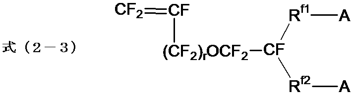
Rf1は、炭素原子-炭素原子間に酸素原子を含んでいてもよいペルフルオロアルキレン基である。上記ペルフルオロアルキレン基中の炭素数は、1以上が好ましく、2以上がより好ましく、20以下が好ましく、10以下がより好ましい。
Rf2は、単結合又は炭素原子-炭素原子間に酸素原子を含んでいてもよいペルフルオロアルキレン基である。上記ペルフルオロアルキレン基中の炭素数は、1以上が好ましく、2以上がより好ましく、20以下が好ましく、10以下がより好ましい。
rは0又は1である。
式中のRf2は、単結合又は炭素原子-炭素原子間に酸素原子を含んでいてもよいペルフルオロアルキレン基である。
式中のAの定義は、上記したとおりである。
Rf2は、単結合又は炭素原子-炭素原子間に酸素原子を含んでいてもよいペルフルオロアルキレン基である。上記ペルフルオロアルキレン基中の炭素数は、1以上が好ましく、2以上がより好ましく、20以下が好ましく、10以下がより好ましい。
rは0又は1である。
式中のRf2は、単結合又は炭素原子-炭素原子間に酸素原子を含んでいてもよいペルフルオロアルキレン基である。
式中のAの定義は、上記したとおりである。
式(2-1)で表される化合物の具体例としては、以下の化合物が挙げられる。式中のwは1~8の整数であり、xは1~5の整数である。
CF2=CF-O-(CF2)w-SO2F
CF2=CF-O-CF2CF(CF3)-O-(CF2)w-SO2F
CF2=CF-[O-CF2CF(CF3)]x-SO2F
CF2=CF-O-(CF2)w-SO2F
CF2=CF-O-CF2CF(CF3)-O-(CF2)w-SO2F
CF2=CF-[O-CF2CF(CF3)]x-SO2F
式(2-2)で表される化合物の具体例としては、以下の化合物が挙げられる。式中のwは、1~8の整数である。
CF2=CF-(CF2)w-SO2F
CF2=CF-CF2-O-(CF2)w-SO2F
CF2=CF-(CF2)w-SO2F
CF2=CF-CF2-O-(CF2)w-SO2F
式(2-3)で表される化合物としては、式(2-3-1)で表される化合物が好ましい。式中のRf3は炭素数1~6の直鎖状のペルフルオロアルキレン基であり、Rf4は単結合又は炭素原子-炭素原子間に酸素原子を含んでいてもよい炭素数1~6の直鎖状のペルフルオロアルキレン基である。式中のr及びAの定義は、上述した通りである。
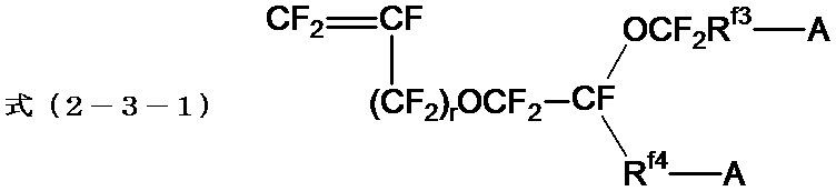
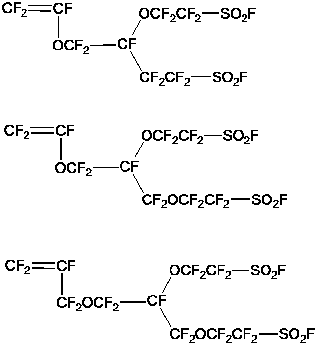
式(2-3-1)で表される化合物の具体例としては、以下が挙げられる。
含フッ素モノマー(S’)は、1種を単独で用いてもよく、2種以上を組み合わせて用いてもよい。
含フッ素ポリマー(S’)の製造には、含フッ素オレフィン及び含フッ素モノマー(S’)に加えて、さらに他のモノマーを用いてもよい。他のモノマーとしては、先に例示したものが挙げられる。
他のモノマーに基づく単位の含有量は、イオン交換性能の維持の点から、含フッ素ポリマー(S’)中の全単位に対して、30質量%以下が好ましい。
含フッ素ポリマー(S’)の製造には、含フッ素オレフィン及び含フッ素モノマー(S’)に加えて、さらに他のモノマーを用いてもよい。他のモノマーとしては、先に例示したものが挙げられる。
他のモノマーに基づく単位の含有量は、イオン交換性能の維持の点から、含フッ素ポリマー(S’)中の全単位に対して、30質量%以下が好ましい。
[ペレット]
本発明のペレット(以下、本ペレットともいう。)は、イオン交換基に変換できる基を有する含フッ素ポリマー(含フッ素ポリマー(I’))を含み、含フッ素ポリマー(I’)のイオン交換基に変換できる基をイオン交換基に変換した際の含フッ素ポリマー(含フッ素ポリマー(I))のイオン交換容量が1.1meq/g樹脂以上であり、光線透過率が30~60%である。
本ペレットを用いれば、電解電圧の安定性に優れたイオン交換膜を形成できる。この理由の詳細は明らかになっていないが、以下の理由によると推測される。
本発明のペレット(以下、本ペレットともいう。)は、イオン交換基に変換できる基を有する含フッ素ポリマー(含フッ素ポリマー(I’))を含み、含フッ素ポリマー(I’)のイオン交換基に変換できる基をイオン交換基に変換した際の含フッ素ポリマー(含フッ素ポリマー(I))のイオン交換容量が1.1meq/g樹脂以上であり、光線透過率が30~60%である。
本ペレットを用いれば、電解電圧の安定性に優れたイオン交換膜を形成できる。この理由の詳細は明らかになっていないが、以下の理由によると推測される。
電解電圧のばらつきの発生原因の1つとして、イオン交換膜の膜厚の不均一性が挙げられる。このようなイオン交換膜の膜厚の不均一性は、含フッ素ポリマーのペレットを用いてフィルム状のイオン交換膜を製造する際に、ペレット同士がくっついて、フィルム成形時に圧力変動が大きくなるために発生すると考えられる。また、ペレット同士のくっつきは、イオン交換基に変換できる基をイオン交換基に変換した際にイオン交換容量の高い含フッ素ポリマーになり得る、含フッ素ポリマーを原料とした場合に顕著になる。
ここで、光線透過率が上記範囲内にある本ペレットは、その表面が粗面化していると推測される。そのため、ペレット同士の接触面積が小さくなって、ペレット同士のくっつきが抑制できると考えられる。これにより、フィルム成形時の圧力変動が抑えられて、膜厚の均一性に優れたイオン交換膜が得られた結果、イオン交換膜を電解装置に適用した際に電解電圧のばらつきを抑制できたと考えられる。
ここで、光線透過率が上記範囲内にある本ペレットは、その表面が粗面化していると推測される。そのため、ペレット同士の接触面積が小さくなって、ペレット同士のくっつきが抑制できると考えられる。これにより、フィルム成形時の圧力変動が抑えられて、膜厚の均一性に優れたイオン交換膜が得られた結果、イオン交換膜を電解装置に適用した際に電解電圧のばらつきを抑制できたと考えられる。
本ペレットの光線透過率は、30~60%であり、電解電圧の安定性により優れる点から、30~50%が好ましく、30~40%が特に好ましい。
本ペレットの光線透過率とは、視感度透過率計(朝日分光社製、MODEL 304又はこれに準じた装置)を用いて測定される可視光透過率(測定波長400~700nm)を意味し、具体的な測定方法は次の通りである。
本ペレットの光線透過率とは、視感度透過率計(朝日分光社製、MODEL 304又はこれに準じた装置)を用いて測定される可視光透過率(測定波長400~700nm)を意味し、具体的な測定方法は次の通りである。
まず、視感度透過率計の試料台に後述の試料ホルダーを載せない状態の可視光透過率が100%となるように、視感度透過率計を調整する。続いて、ペレットを嵌め込むための所定サイズの穴(例えば、縦2~3mm、横2~3mmの矩形の穴)が開いた試料ホルダーを試料台に設置して、試料ホルダーの穴にペレットを嵌め込む前の可視光透過率が25%となるように光線強度を調整する。
次に、試料ホルダーの穴と同サイズのペレットを試料ホルダーの穴に嵌め込み、可視光透過率を測定する。なお、ペレットの可視光透過率の測定は、1つのペレットに対して複数箇所行って、その算術平均値を求める。例えば、ペレットが円柱状である場合、ペレットの側面に光が照射されるように試料ホルダーの穴にペレットを嵌め込み、ペレットを円周方向に90度ずつ回転させて、1つのペレットに対して3箇所の可視光透過率を測定して、これの算術平均値を求める。
そして、試料ホルダーの穴にペレットを嵌め込む前の可視光透過率(25%)を100%と換算したときの、ペレットの可視光透過率の値を算出して(すなわち、測定したペレットの可視光透過率を4倍したもの)、これを本ペレットの光線透過率(%)とする。
次に、試料ホルダーの穴と同サイズのペレットを試料ホルダーの穴に嵌め込み、可視光透過率を測定する。なお、ペレットの可視光透過率の測定は、1つのペレットに対して複数箇所行って、その算術平均値を求める。例えば、ペレットが円柱状である場合、ペレットの側面に光が照射されるように試料ホルダーの穴にペレットを嵌め込み、ペレットを円周方向に90度ずつ回転させて、1つのペレットに対して3箇所の可視光透過率を測定して、これの算術平均値を求める。
そして、試料ホルダーの穴にペレットを嵌め込む前の可視光透過率(25%)を100%と換算したときの、ペレットの可視光透過率の値を算出して(すなわち、測定したペレットの可視光透過率を4倍したもの)、これを本ペレットの光線透過率(%)とする。
本ペレットに含まれる含フッ素ポリマー(I’)は、上述の本製造方法で用いた含フッ素ポリマー(I’)と同様であり、イオン交換容量等の好適態様も同様である。
本ペレットの形状、サイズ、表面状態及び用途等についても、上述の本製造方法により得られたペレットと同様である。
本ペレットは、光線透過率を上記範囲内にするのが容易である点から、上述の本製造方法により製造するのが好ましい。
本ペレットの形状、サイズ、表面状態及び用途等についても、上述の本製造方法により得られたペレットと同様である。
本ペレットは、光線透過率を上記範囲内にするのが容易である点から、上述の本製造方法により製造するのが好ましい。
[イオン交換膜]
本発明のイオン交換膜(以下、本イオン交換膜ともいう。)は、上述の本ペレットを用いて形成される。
本イオン交換膜の好適な製造方法の一例としては、本ペレットを用いて上述のイオン交換基に変換できる基を有する含フッ素ポリマー(含フッ素ポリマー(I’))を含む前駆体膜を形成した後、前駆体膜に含まれるイオン交換基に変換できる基をイオン交換基に変換して、イオン交換基を有する含フッ素ポリマー(含フッ素ポリマー(I))を含む本イオン交換膜を得る方法が挙げられる。
本発明のイオン交換膜(以下、本イオン交換膜ともいう。)は、上述の本ペレットを用いて形成される。
本イオン交換膜の好適な製造方法の一例としては、本ペレットを用いて上述のイオン交換基に変換できる基を有する含フッ素ポリマー(含フッ素ポリマー(I’))を含む前駆体膜を形成した後、前駆体膜に含まれるイオン交換基に変換できる基をイオン交換基に変換して、イオン交換基を有する含フッ素ポリマー(含フッ素ポリマー(I))を含む本イオン交換膜を得る方法が挙げられる。
〔前駆体膜の製造方法〕
前駆体膜の製造方法としては、押し出し法が挙げられる。具体的には、本ペレットを公知のフィルム製造用の溶融押出機に供給して、本ペレットの溶融物を溶融押出機のノズル(例えば、Tダイ)から押し出して、フィルム状に成形して、前駆体膜を得る方法である。本ペレットの溶融温度は、150~350℃が好ましく、200~300℃が特に好ましい。
前駆体膜の製造方法としては、押し出し法が挙げられる。具体的には、本ペレットを公知のフィルム製造用の溶融押出機に供給して、本ペレットの溶融物を溶融押出機のノズル(例えば、Tダイ)から押し出して、フィルム状に成形して、前駆体膜を得る方法である。本ペレットの溶融温度は、150~350℃が好ましく、200~300℃が特に好ましい。
前駆体膜には、補強材が埋め込まれていてもよい。補強材は、公知の方法によって前駆体膜中に埋め込むことができる。例えば、多層構造のイオン交換膜を形成する場合、前駆体膜で補強材を挟み込む方法が挙げられる。また、本ペレットの溶融物を補強材の両面にコーティングする方法によっても、前駆体膜中に補強材を埋め込むことができる。
補強材の具体例としては、補強布(好ましくは、織布)、フィブリル、多孔体が挙げられ、これらの中でも補強布が好ましい。
補強布は、経糸と緯糸とからなり、経糸と緯糸とが直交しているのが好ましい。補強布は、補強糸と犠牲糸とからなるのが好ましい。
補強糸は、アルカリ性水溶液に溶出しない材料からなる糸である。補強糸としては、ポリテトラフルオロエチレン、ポリフェニレンサルファイド、ナイロン及びポリプロピレンからなる群より選択される少なくとも1種の補強糸が好ましい。
犠牲糸は、1本のフィラメントからなるモノフィラメントであっても、2本以上のフィラメントからなるマルチフィラメントであってもよい。
イオン交換膜の製造時及びイオン交換膜の装置への装着時などのハンドリング中は、犠牲糸によってイオン交換膜の強度が保たれるが、装置の運転環境下で犠牲糸が溶解するためイオン交換膜の抵抗を低下させることができる。
補強布は、経糸と緯糸とからなり、経糸と緯糸とが直交しているのが好ましい。補強布は、補強糸と犠牲糸とからなるのが好ましい。
補強糸は、アルカリ性水溶液に溶出しない材料からなる糸である。補強糸としては、ポリテトラフルオロエチレン、ポリフェニレンサルファイド、ナイロン及びポリプロピレンからなる群より選択される少なくとも1種の補強糸が好ましい。
犠牲糸は、1本のフィラメントからなるモノフィラメントであっても、2本以上のフィラメントからなるマルチフィラメントであってもよい。
イオン交換膜の製造時及びイオン交換膜の装置への装着時などのハンドリング中は、犠牲糸によってイオン交換膜の強度が保たれるが、装置の運転環境下で犠牲糸が溶解するためイオン交換膜の抵抗を低下させることができる。
〔イオン交換膜の製造方法〕
含フッ素ポリマー(I)を含む本イオン交換膜は、前駆体膜に含まれる含フッ素ポリマー(I’)のイオン交換基に変換できる基をイオン交換基に変換して得られる。
前駆体膜中のイオン交換基に変換できる基をイオン交換基に変換する方法の具体例としては、前駆体膜に加水分解処理又は酸型化処理等の処理を施す方法が挙げられる。
なかでも、前駆体膜とアルカリ性水溶液とを接触させる方法が好ましい。
含フッ素ポリマー(I)を含む本イオン交換膜は、前駆体膜に含まれる含フッ素ポリマー(I’)のイオン交換基に変換できる基をイオン交換基に変換して得られる。
前駆体膜中のイオン交換基に変換できる基をイオン交換基に変換する方法の具体例としては、前駆体膜に加水分解処理又は酸型化処理等の処理を施す方法が挙げられる。
なかでも、前駆体膜とアルカリ性水溶液とを接触させる方法が好ましい。
前駆体膜とアルカリ性水溶液とを接触させる方法の具体例としては、前駆体膜をアルカリ性水溶液中に浸漬する方法、前駆体膜の表面にアルカリ性水溶液をスプレー塗布する方法が挙げられる。
アルカリ性水溶液の温度は、イオン交換膜の生産性の観点から30℃以上100℃未満が好ましく、前駆体膜とアルカリ性水溶液との接触時間は、3~300分間が好ましい。
アルカリ性水溶液の温度は、イオン交換膜の生産性の観点から30℃以上100℃未満が好ましく、前駆体膜とアルカリ性水溶液との接触時間は、3~300分間が好ましい。
アルカリ性水溶液は、アルカリ金属水酸化物、水溶性有機溶剤及び水を含むのが好ましい。アルカリ金属水酸化物の具体例としては、水酸化ナトリウム、水酸化カリウムが挙げられ、水酸化カリウムが好ましい。アルカリ金属水酸化物は、1種単独で用いても2種以上を併用してもよい。
本明細書において、水溶性有機溶剤とは、水に容易に溶解する有機溶剤であり、具体的には、水1000ml(20℃)に対する溶解性が、0.1g以上の有機溶剤が好ましく、0.5g以上の有機溶剤がより好ましい。水溶性有機溶剤は、非プロトン性有機溶剤、アルコール類及びアミノアルコール類からなる群より選択される少なくとも1種を含むのが好ましく、非プロトン性有機溶剤を含むのがより好ましい。水溶性有機溶剤は、1種単独で用いても2種以上を併用してもよい。
本明細書において、水溶性有機溶剤とは、水に容易に溶解する有機溶剤であり、具体的には、水1000ml(20℃)に対する溶解性が、0.1g以上の有機溶剤が好ましく、0.5g以上の有機溶剤がより好ましい。水溶性有機溶剤は、非プロトン性有機溶剤、アルコール類及びアミノアルコール類からなる群より選択される少なくとも1種を含むのが好ましく、非プロトン性有機溶剤を含むのがより好ましい。水溶性有機溶剤は、1種単独で用いても2種以上を併用してもよい。
非プロトン性有機溶剤の具体例としては、ジメチルスルホキシド、N,N-ジメチルホルムアミド、N,N-ジメチルアセトアミド、N-メチル-2-ピロリドン、N-エチル-2-ピロリドンが挙げられ、ジメチルスルホキシドが好ましい。
アルコール類の具体例としては、メタノール、エタノール、イソプロパノール、ブタノール、メトキシエトキシエタノール、ブトキシエタノール、ブチルカルビトール、ヘキシルオキシエタノール、オクタノール、1-メトキシ-2-プロパノール、エチレングリコールが挙げられる。
アミノアルコール類の具体例としては、エタノールアミン、N-メチルエタノールアミン、N-エチルエタノールアミン、1-アミノ-2-プロパノール、1-アミノ-3-プロパノール、2-アミノエトキシエタノール、2-アミノチオエトキシエタノール、2-アミノ-2-メチル-1-プロパノールが挙げられる。
アルコール類の具体例としては、メタノール、エタノール、イソプロパノール、ブタノール、メトキシエトキシエタノール、ブトキシエタノール、ブチルカルビトール、ヘキシルオキシエタノール、オクタノール、1-メトキシ-2-プロパノール、エチレングリコールが挙げられる。
アミノアルコール類の具体例としては、エタノールアミン、N-メチルエタノールアミン、N-エチルエタノールアミン、1-アミノ-2-プロパノール、1-アミノ-3-プロパノール、2-アミノエトキシエタノール、2-アミノチオエトキシエタノール、2-アミノ-2-メチル-1-プロパノールが挙げられる。
アルカリ金属水酸化物の含有量は、アルカリ性水溶液中、1~60質量%が好ましい。 水溶性有機溶剤の含有量は、アルカリ性水溶液中、1~60質量%が好ましい。
アルカリ金属水酸化物及び水溶性有機溶剤の含有量が上記範囲内であれば、加水分解処理が速やかに完了して、本イオン交換膜の生産性が向上する。
水の含有量は、アルカリ性水溶液中、39~80質量%が好ましい。
アルカリ金属水酸化物及び水溶性有機溶剤の含有量が上記範囲内であれば、加水分解処理が速やかに完了して、本イオン交換膜の生産性が向上する。
水の含有量は、アルカリ性水溶液中、39~80質量%が好ましい。
前駆体膜とアルカリ性水溶液との接触後に、アルカリ性水溶液を除去する処理を行ってもよい。アルカリ性水溶液を除去する方法としては、例えば、アルカリ性水溶液に接触させた本イオン交換膜を水洗する方法が挙げられる。
前駆体膜とアルカリ性水溶液との接触後に、得られたイオン交換膜を乾燥する処理をしてもよい。乾燥処理としては加熱処理が好ましく、その際の加熱温度は50~160℃が好ましい。加熱時間は、0.1~24時間が好ましい。
前駆体膜とアルカリ性水溶液との接触後に、得られたイオン交換膜を乾燥する処理をしてもよい。乾燥処理としては加熱処理が好ましく、その際の加熱温度は50~160℃が好ましい。加熱時間は、0.1~24時間が好ましい。
前駆体膜中のイオン交換基に変換できる基をイオン交換基に変換した後、本イオン交換膜をカリウムイオン、ナトリウムイオン、又は水素イオンを含む水溶液に接触させ、イオン交換基の対イオン(カチオン)を置換してもよい。イオン交換基のカチオンを、アルカリ水中に存在するカチオンと同じカチオンに置換することによって、置換したカチオンが存在する環境下でのアルカリ水電解に供することができ、本イオン交換膜の寸法安定性が向上する。
前駆体膜又は本イオン交換膜の表面に親水化層を形成してもよい。親水化層は、前駆体膜又は本イオン交換膜の表面の少なくとも一方の面に形成すればよい。
親水化層の具体例としては、無機物粒子を含む無機物粒子層が挙げられる。無機物粒子は、酸又はアルカリに対する耐食性に優れ、親水性を有するのが好ましい。具体的には、第4族元素又は第14族元素の酸化物、窒化物及び炭化物からなる群より選択される少なくとも1種が好ましく、SiO2、SiC、ZrO2及びZrCからなる群より選択される少なくとも1種がより好ましく、ZrO2が特に好ましい。
親水化層はバインダーを含んでいてもよい。バインダーとしては、公知の親水化層(ガス解放層)に用いられる公知のバインダーを採用でき、例えば、メチルセルロース、スルホン酸基を有する含フッ素ポリマーが挙げられる。
親水化層の形成方法の具体例としては、無機物粒子及びバインダーを含む溶液を前駆体膜又は本イオン交換膜に塗布する方法が挙げられる。
親水化層の具体例としては、無機物粒子を含む無機物粒子層が挙げられる。無機物粒子は、酸又はアルカリに対する耐食性に優れ、親水性を有するのが好ましい。具体的には、第4族元素又は第14族元素の酸化物、窒化物及び炭化物からなる群より選択される少なくとも1種が好ましく、SiO2、SiC、ZrO2及びZrCからなる群より選択される少なくとも1種がより好ましく、ZrO2が特に好ましい。
親水化層はバインダーを含んでいてもよい。バインダーとしては、公知の親水化層(ガス解放層)に用いられる公知のバインダーを採用でき、例えば、メチルセルロース、スルホン酸基を有する含フッ素ポリマーが挙げられる。
親水化層の形成方法の具体例としては、無機物粒子及びバインダーを含む溶液を前駆体膜又は本イオン交換膜に塗布する方法が挙げられる。
本イオン交換膜は、単層であってもよく、多層構造であってもよい。多層構造のイオン交換膜は、例えば、共押し出し法によってイオン交換基に変換できる基を有する含フッ素ポリマーからなる複数の層を積層させて得られた前駆体膜を用いて製造できる。
本イオン交換膜の膜厚は、一定の強度を保つ点から、30μm以上が好ましく、40μm以上がより好ましく、電流効率及び電圧効率を高める点から、500μm以下が好ましく、300μm以下がより好ましく、180μm以下がさらに好ましい。
〔含フッ素ポリマー(I)〕
含フッ素ポリマー(I)は、前駆体膜に含まれる含フッ素ポリマー(I’)のイオン交換基に変換できる基をイオン交換基に変換して得られる含フッ素ポリマーである。
含フッ素ポリマー(I)は、本発明の効果がより発揮できる点から、カルボン酸型官能基を有する含フッ素ポリマー(以下、含フッ素ポリマー(C)ともいう。)、又は、スルホン酸型官能基を有する含フッ素ポリマー(以下、含フッ素ポリマー(S)ともいう。)が好ましい。
以下、各含フッ素ポリマーについて詳述する。
含フッ素ポリマー(I)は、前駆体膜に含まれる含フッ素ポリマー(I’)のイオン交換基に変換できる基をイオン交換基に変換して得られる含フッ素ポリマーである。
含フッ素ポリマー(I)は、本発明の効果がより発揮できる点から、カルボン酸型官能基を有する含フッ素ポリマー(以下、含フッ素ポリマー(C)ともいう。)、又は、スルホン酸型官能基を有する含フッ素ポリマー(以下、含フッ素ポリマー(S)ともいう。)が好ましい。
以下、各含フッ素ポリマーについて詳述する。
(含フッ素ポリマー(C))
含フッ素ポリマー(C)は、上述の含フッ素ポリマー(C’)のカルボン酸型官能基に変換できる基をカルボン酸基に変換して得るのが好ましい。
含フッ素ポリマー(C)は、含フッ素オレフィンに基づく単位及びカルボン酸型官能基及びフッ素原子を有するモノマーに基づく単位を含むのが好ましい。
含フッ素オレフィンとしては、先に例示したものが挙げられる。
含フッ素オレフィンに基づく単位は、1種単独で含まれていてもよく、2種以上が含まれていてもよい。
含フッ素ポリマー(C)は、上述の含フッ素ポリマー(C’)のカルボン酸型官能基に変換できる基をカルボン酸基に変換して得るのが好ましい。
含フッ素ポリマー(C)は、含フッ素オレフィンに基づく単位及びカルボン酸型官能基及びフッ素原子を有するモノマーに基づく単位を含むのが好ましい。
含フッ素オレフィンとしては、先に例示したものが挙げられる。
含フッ素オレフィンに基づく単位は、1種単独で含まれていてもよく、2種以上が含まれていてもよい。
カルボン酸型官能基及びフッ素原子を有するモノマーに基づく単位としては、下式(1C)で表される単位が好ましい。
式(1C):-[CF2-CF((O)p-(CF2)q-(CF2CFX)r-(O)s-(CF2)t-(CF2CFX’)u-COOMC)]-
MCは水素原子、アルカリ金属又は第4級アンモニウムカチオンである。
X、X’、p、q、r、s、t及びuは、上記式(1)と同様である。
式(1C):-[CF2-CF((O)p-(CF2)q-(CF2CFX)r-(O)s-(CF2)t-(CF2CFX’)u-COOMC)]-
MCは水素原子、アルカリ金属又は第4級アンモニウムカチオンである。
X、X’、p、q、r、s、t及びuは、上記式(1)と同様である。
式(1C)で表される単位の具体例としては、下記の単位が挙げられ、p=1、q=0、r=1、s=0~1、t=0~3、u=0~1である化合物が好ましい。
-[CF2-CF(O-CF2CF2-COOMC)]-、
-[CF2-CF(O-CF2CF2CF2-COOMC)]-、
-[CF2-CF(O-CF2CF2CF2CF2-COOMC)]-、
-[CF2-CF(O-CF2CF2-O-CF2CF2-COOMC)]-、
-[CF2-CF(O-CF2CF2-O-CF2CF2CF2-COOMC)]-、
-[CF2-CF(O-CF2CF2-O-CF2CF2CF2CF2-COOMC)]-、
-[CF2-CF(O-CF2CF2CF2-O-CF2CF2-COOMC)]-、
-[CF2-CF(O-CF2CF(CF3)-O-CF2CF2-COOMC)]-、
-[CF2-CF(O-CF2CF(CF3)-O-CF2CF2CF2-COOMC)]-。
カルボン酸型官能基及びフッ素原子を有するモノマーに基づく単位は、1種単独で含まれていてもよく、2種以上が含まれていてもよい。
-[CF2-CF(O-CF2CF2-COOMC)]-、
-[CF2-CF(O-CF2CF2CF2-COOMC)]-、
-[CF2-CF(O-CF2CF2CF2CF2-COOMC)]-、
-[CF2-CF(O-CF2CF2-O-CF2CF2-COOMC)]-、
-[CF2-CF(O-CF2CF2-O-CF2CF2CF2-COOMC)]-、
-[CF2-CF(O-CF2CF2-O-CF2CF2CF2CF2-COOMC)]-、
-[CF2-CF(O-CF2CF2CF2-O-CF2CF2-COOMC)]-、
-[CF2-CF(O-CF2CF(CF3)-O-CF2CF2-COOMC)]-、
-[CF2-CF(O-CF2CF(CF3)-O-CF2CF2CF2-COOMC)]-。
カルボン酸型官能基及びフッ素原子を有するモノマーに基づく単位は、1種単独で含まれていてもよく、2種以上が含まれていてもよい。
含フッ素ポリマー(C)は、含フッ素オレフィンに基づく単位、及び、カルボン酸型官能基及びフッ素原子を有するモノマーに基づく単位以外の、他のモノマーに基づく単位を含んでいてもよい。
他のモノマーの具体例としては、先に例示したものが挙げられる。他のモノマーに基づく単位の含有量は、イオン交換性能の維持の点から、含フッ素ポリマー(C)中の全単位に対して、30質量%以下が好ましい。
他のモノマーの具体例としては、先に例示したものが挙げられる。他のモノマーに基づく単位の含有量は、イオン交換性能の維持の点から、含フッ素ポリマー(C)中の全単位に対して、30質量%以下が好ましい。
(含フッ素ポリマー(S))
含フッ素ポリマー(S)は、上述の含フッ素ポリマー(S’)のスルホン酸型官能基に変換できる基をスルホン酸基に変換して得るのが好ましい。
含フッ素ポリマー(S)は、含フッ素オレフィンに基づく単位及びスルホン酸型官能基及びフッ素原子を有するモノマーに基づく単位を含むのが好ましい。
含フッ素オレフィンとしては、先に例示したものが挙げられる。
含フッ素オレフィンに基づく単位は、1種単独で含まれていてもよく、2種以上が含まれていてもよい。
含フッ素ポリマー(S)は、上述の含フッ素ポリマー(S’)のスルホン酸型官能基に変換できる基をスルホン酸基に変換して得るのが好ましい。
含フッ素ポリマー(S)は、含フッ素オレフィンに基づく単位及びスルホン酸型官能基及びフッ素原子を有するモノマーに基づく単位を含むのが好ましい。
含フッ素オレフィンとしては、先に例示したものが挙げられる。
含フッ素オレフィンに基づく単位は、1種単独で含まれていてもよく、2種以上が含まれていてもよい。
スルホン酸型官能基及びフッ素原子を有するモノマーに基づく単位としては、式(2S)で表される単位が好ましい。
式(2S): -[CF2-CF(-L-(SO3MS)n)]-
式(2S): -[CF2-CF(-L-(SO3MS)n)]-
式(2S)中、L及びnの定義は、上記式(2)と同様である。
MSは、水素原子、アルカリ金属又は第4級アンモニウムカチオンである。
MSは、水素原子、アルカリ金属又は第4級アンモニウムカチオンである。
式(2S)で表される単位としては、式(2S-1)で表される単位、式(2S-2)で表される単位、又は、式(2S-3)で表される単位が好ましい。
式(2S-1) -[CF2-CF(-O-Rf1-SO3MS)]-
式(2S-2) -[CF2-CF(-Rf1-SO3MS)]-
式(2S-1) -[CF2-CF(-O-Rf1-SO3MS)]-
式(2S-2) -[CF2-CF(-Rf1-SO3MS)]-
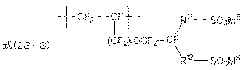
式(2S-1)~式(2S-3)中、Rf1、Rf2及びrの定義は、上記式(2-1)~式(2-3)と同様である。
MSは水素原子、アルカリ金属又は第4級アンモニウムカチオンである。
MSは水素原子、アルカリ金属又は第4級アンモニウムカチオンである。
式(2S-1)で表される単位の具体例としては、以下の単位が挙げられる。式中のwは1~8の整数であり、xは1~5の整数である。式中のMSの定義は、上述した通りである。
-[CF2-CF(-O-(CF2)w-SO3MS)]-
-[CF2-CF(-O-CF2CF(CF3)-O-(CF2)w-SO3MS)]-
-[CF2-CF(-(O-CF2CF(CF3))x-SO3MS)]-
-[CF2-CF(-O-(CF2)w-SO3MS)]-
-[CF2-CF(-O-CF2CF(CF3)-O-(CF2)w-SO3MS)]-
-[CF2-CF(-(O-CF2CF(CF3))x-SO3MS)]-
式(2S-2)で表される単位の具体例としては、以下の単位が挙げられる。式中のwは1~8の整数である。式中のMSの定義は、上述した通りである。
-[CF2-CF(-(CF2)w-SO3MS)]-
-[CF2-CF(-CF2-O-(CF2)w-SO3MS)]-
-[CF2-CF(-(CF2)w-SO3MS)]-
-[CF2-CF(-CF2-O-(CF2)w-SO3MS)]-
式(2S-3)で表される単位としては、式(2S-3-1)で表される単位が好ましい。式中のMSの定義は、上述した通りである。

式(2S-3-1)中、Rf3、Rf4及びrの定義は、上記式(2-3-1)と同様である。MSの定義は、上述した通りである。
式(2S-3)で表される単位の具体例としては、以下が挙げられる。

スルホン酸型官能基及びフッ素原子を有するモノマーに基づく単位は、1種単独で含まれていてもよく、2種以上が含まれていてもよい。
含フッ素ポリマー(S)は、含フッ素オレフィンに基づく単位、及び、スルホン酸型官能基及びフッ素原子を有するモノマーに基づく単位以外の、他のモノマーに基づく単位を含んでいてもよい。
他のモノマーの具体例としては、先に例示したものが挙げられる。他のモノマーに基づく単位の含有量は、イオン交換性能の維持の点から、含フッ素ポリマー(S)中の全単位に対して、30質量%以下が好ましい。
他のモノマーの具体例としては、先に例示したものが挙げられる。他のモノマーに基づく単位の含有量は、イオン交換性能の維持の点から、含フッ素ポリマー(S)中の全単位に対して、30質量%以下が好ましい。
〔イオン交換膜の用途〕
本イオン交換膜の用途の具体例としては、固体高分子型燃料電池、メタノール直接型燃料電池、レドックスフロー電池、空気電池などの各種電池用途、固体高分子型水電解、アルカリ型水電解、オゾン水電解、食塩電解、有機物電解や、塩化物又は酸化物等の各種電気分解装置が挙げられる。上記用途以外にも様々なタイプの電気化学セルでのセパレーターや固体電極として、セルの結合部分での選択的なカチオン輸送に用いることができる。また、電気化学関連の用途以外にも、センサー用途として各種ガスセンサー、バイオセンサー、発光デバイス、光学デバイス、有機物センサー、及び、カーボンナノチューブの可溶化、アクチュエーター、触媒用途等に用いることができる。
本イオン交換膜の用途の具体例としては、固体高分子型燃料電池、メタノール直接型燃料電池、レドックスフロー電池、空気電池などの各種電池用途、固体高分子型水電解、アルカリ型水電解、オゾン水電解、食塩電解、有機物電解や、塩化物又は酸化物等の各種電気分解装置が挙げられる。上記用途以外にも様々なタイプの電気化学セルでのセパレーターや固体電極として、セルの結合部分での選択的なカチオン輸送に用いることができる。また、電気化学関連の用途以外にも、センサー用途として各種ガスセンサー、バイオセンサー、発光デバイス、光学デバイス、有機物センサー、及び、カーボンナノチューブの可溶化、アクチュエーター、触媒用途等に用いることができる。
以下、例を挙げて本発明を具体的に説明する。但し、本発明はこれらの例に限定されない。なお、後述する表中における各成分の配合量は、質量基準を示す。
[イオン交換膜の膜厚]
イオン交換膜の断面を光学顕微鏡にて観察し、画像解析ソフトを用いて求めた。
イオン交換膜の断面を光学顕微鏡にて観察し、画像解析ソフトを用いて求めた。
[含フッ素ポリマーのイオン交換容量]
乾燥窒素を流したグローブボックス中にイオン交換基を有する含フッ素ポリマーを24時間保存し、含フッ素ポリマーの乾燥質量を測定した。その後、含フッ素ポリマーを2モル/Lの塩化ナトリウム水溶液に60℃で1時間浸漬した。含フッ素ポリマーを超純水で洗浄した後、取り出し、含フッ素ポリマーを浸漬していた液を0.1モル/Lの水酸化ナトリウム水溶液で滴定して、含フッ素ポリマーのイオン交換容量(meq/g樹脂)を求めた。
乾燥窒素を流したグローブボックス中にイオン交換基を有する含フッ素ポリマーを24時間保存し、含フッ素ポリマーの乾燥質量を測定した。その後、含フッ素ポリマーを2モル/Lの塩化ナトリウム水溶液に60℃で1時間浸漬した。含フッ素ポリマーを超純水で洗浄した後、取り出し、含フッ素ポリマーを浸漬していた液を0.1モル/Lの水酸化ナトリウム水溶液で滴定して、含フッ素ポリマーのイオン交換容量(meq/g樹脂)を求めた。
[ペレットの光線透過率]
まず、視感度透過率計(朝日分光社製、TLV-304-BP)の試料台に後述の試料ホルダーを載せない状態の可視光透過率(測定波長:400~700nm)が100%となるように、視感度透過率計を調整した。
次に、ペレットを嵌め込むための矩形の穴(穴のサイズ:縦2~3mm×横2~3mm)が開いた試料ホルダー(厚み0.7mm)を試料台に設置して、試料ホルダーの穴にペレットを嵌め込む前の可視光透過率が25%となるように光線強度を調整した。
次に、試料ホルダーの穴と略同サイズのペレット(直径2~3mm、長さ2~3mmの円柱状)を、ペレットの側面に光が照射されるように試料ホルダーの穴に嵌め込み、可視光透過率を測定した。なお、ペレットの可視光透過率の測定は、ペレットを円周方向に90度ずつ回転させて、1つのペレットに対して3箇所の光線透過率を測定して、これの算術平均値を求めた。
そして、試料ホルダーの穴にペレットを嵌め込む前の可視光透過率(25%)を100%と換算したときの、ペレットの可視光透過率の値を算出して(すなわち、測定したペレットの可視光透過率を4倍したもの)、これをペレットの光線透過率(%)とした。
まず、視感度透過率計(朝日分光社製、TLV-304-BP)の試料台に後述の試料ホルダーを載せない状態の可視光透過率(測定波長:400~700nm)が100%となるように、視感度透過率計を調整した。
次に、ペレットを嵌め込むための矩形の穴(穴のサイズ:縦2~3mm×横2~3mm)が開いた試料ホルダー(厚み0.7mm)を試料台に設置して、試料ホルダーの穴にペレットを嵌め込む前の可視光透過率が25%となるように光線強度を調整した。
次に、試料ホルダーの穴と略同サイズのペレット(直径2~3mm、長さ2~3mmの円柱状)を、ペレットの側面に光が照射されるように試料ホルダーの穴に嵌め込み、可視光透過率を測定した。なお、ペレットの可視光透過率の測定は、ペレットを円周方向に90度ずつ回転させて、1つのペレットに対して3箇所の光線透過率を測定して、これの算術平均値を求めた。
そして、試料ホルダーの穴にペレットを嵌め込む前の可視光透過率(25%)を100%と換算したときの、ペレットの可視光透過率の値を算出して(すなわち、測定したペレットの可視光透過率を4倍したもの)、これをペレットの光線透過率(%)とした。
[ホッパー内のブリッジの有無]
ペレットをフィルム製造用の溶融押出機のホッパーに供給してフィルム状のイオン交換膜(前駆体膜)を製造する際に、ホッパー内でペレット同士がくっついて、ホッパーと連結したスクリュー部(ペレットの溶融混練を行う部分)にペレットが供給されない状態(ブリッジ)の発生の有無を確認した。
具体的には、溶融押出機(単軸、スクリュー径:30mm)を用いて、ペレットの溶融温度を260℃に設定して3時間連続でフィルム(Tダイの幅:350mm)を製造した際に、ホッパー内でブリッジが発生するかどうかを判定した。
ペレットをフィルム製造用の溶融押出機のホッパーに供給してフィルム状のイオン交換膜(前駆体膜)を製造する際に、ホッパー内でペレット同士がくっついて、ホッパーと連結したスクリュー部(ペレットの溶融混練を行う部分)にペレットが供給されない状態(ブリッジ)の発生の有無を確認した。
具体的には、溶融押出機(単軸、スクリュー径:30mm)を用いて、ペレットの溶融温度を260℃に設定して3時間連続でフィルム(Tダイの幅:350mm)を製造した際に、ホッパー内でブリッジが発生するかどうかを判定した。
[フィルムの成形圧力変動]
溶融押出機(単軸、スクリュー径:30mm)を用いて、ペレットの溶融温度を260℃に設定して3時間連続でフィルム(Tダイの幅:350mm)を製造した際に、運転直後(0時間)から運転終了(3時間)まで30分毎にフィルムの成形圧力を測定し、以下の式にしたがって、フィルムの成形圧力変動(%)を算出した。成形圧力の変動が小さい程、厚みの均一性に優れたフィルムが得られるために好ましいといえる。
なお、フィルムの成形圧力は、スクリュー先端部に設置した樹脂圧力センサー(理化工業社製の「CZ-200P」)によって測定した。
フィルムの成形圧力変動(%)=[3σ/(時間毎に測定したフィルムの成形圧力の算術平均値)]×100
但し、σ:時間毎に測定したフィルムの成形圧力の標準偏差である。
溶融押出機(単軸、スクリュー径:30mm)を用いて、ペレットの溶融温度を260℃に設定して3時間連続でフィルム(Tダイの幅:350mm)を製造した際に、運転直後(0時間)から運転終了(3時間)まで30分毎にフィルムの成形圧力を測定し、以下の式にしたがって、フィルムの成形圧力変動(%)を算出した。成形圧力の変動が小さい程、厚みの均一性に優れたフィルムが得られるために好ましいといえる。
なお、フィルムの成形圧力は、スクリュー先端部に設置した樹脂圧力センサー(理化工業社製の「CZ-200P」)によって測定した。
フィルムの成形圧力変動(%)=[3σ/(時間毎に測定したフィルムの成形圧力の算術平均値)]×100
但し、σ:時間毎に測定したフィルムの成形圧力の標準偏差である。
[電解電圧の変動]
イオン交換膜を、有効通電面積が1.5dm2(電解面サイズが縦150mm×横100mm)の試験用電解槽内に配置した。電解槽では、陰極として、チタンのパンチドメタル(短径4mm、長径8mm)に酸化ルテニウムと酸化イリジウムと酸化チタンの固溶体を被覆したものを用い、陰極としてSUS304製パンチドメタル(短径5mm、長径10mm)にルテニウム入りラネーニッケルを電着したものを用い、電極とイオン交換膜が直接接触し、ギャップが生じないように設置した。
陰極室から排出される水酸化ナトリウム濃度を32質量%、陽極室に供給する塩化ナトリウム濃度を200g/Lとなるように調整しながら、温度90℃、電流密度:6kA/m2の条件で、塩化ナトリウム水溶液の電解を行い、運転開始から3日後の電解電圧(V)を測定した。
10枚のイオン交換膜について電解電圧を測定し、以下の式にしたがって電解電圧の変動を算出した。電解電圧の変動が小さい程、電解電圧の安定性に優れているといえる。
電解電圧の変動(%)=[{(電解電圧の最大値)-(電解電圧の最小値)}/(電解電圧の平均値)]×100
イオン交換膜を、有効通電面積が1.5dm2(電解面サイズが縦150mm×横100mm)の試験用電解槽内に配置した。電解槽では、陰極として、チタンのパンチドメタル(短径4mm、長径8mm)に酸化ルテニウムと酸化イリジウムと酸化チタンの固溶体を被覆したものを用い、陰極としてSUS304製パンチドメタル(短径5mm、長径10mm)にルテニウム入りラネーニッケルを電着したものを用い、電極とイオン交換膜が直接接触し、ギャップが生じないように設置した。
陰極室から排出される水酸化ナトリウム濃度を32質量%、陽極室に供給する塩化ナトリウム濃度を200g/Lとなるように調整しながら、温度90℃、電流密度:6kA/m2の条件で、塩化ナトリウム水溶液の電解を行い、運転開始から3日後の電解電圧(V)を測定した。
10枚のイオン交換膜について電解電圧を測定し、以下の式にしたがって電解電圧の変動を算出した。電解電圧の変動が小さい程、電解電圧の安定性に優れているといえる。
電解電圧の変動(%)=[{(電解電圧の最大値)-(電解電圧の最小値)}/(電解電圧の平均値)]×100
[含フッ素ポリマー(S’-1)の製造]
CF2=CF2と下記式(X1)で表されるモノマー(X1)とを共重合して、含フッ素ポリマー(S’-1)(イオン交換容量:1.1meq/g樹脂)を得た。なお、各モノマーの配合比は、含フッ素ポリマー(S’-1)のイオン交換容量が上記値となるように調節した。
CF2=CF-O-CF2CF(CF3)-O-CF2CF2-SO2F (X1)
CF2=CF2と下記式(X1)で表されるモノマー(X1)とを共重合して、含フッ素ポリマー(S’-1)(イオン交換容量:1.1meq/g樹脂)を得た。なお、各モノマーの配合比は、含フッ素ポリマー(S’-1)のイオン交換容量が上記値となるように調節した。
CF2=CF-O-CF2CF(CF3)-O-CF2CF2-SO2F (X1)
[含フッ素ポリマー(S’-2)の製造]
CF2=CF2と上記式(X1)で表されるモノマー(X1)とを共重合して、含フッ素ポリマー(S’-2)(イオン交換容量:1.25meq/g樹脂)を得た。なお、各モノマーの配合比は、含フッ素ポリマー(S’-2)のイオン交換容量が上記値となるように調節した。
CF2=CF2と上記式(X1)で表されるモノマー(X1)とを共重合して、含フッ素ポリマー(S’-2)(イオン交換容量:1.25meq/g樹脂)を得た。なお、各モノマーの配合比は、含フッ素ポリマー(S’-2)のイオン交換容量が上記値となるように調節した。
[含フッ素ポリマー(S’-3)の製造]
CF2=CF2と下記式(X2)で表されるモノマー(X2)とを共重合して、含フッ素ポリマー(S’-3)(イオン交換容量:1.90meq/g樹脂)を得た。なお、各モノマーの配合比は、含フッ素ポリマー(S’-3)のイオン交換容量が上記値となるように調節した。
CF2=CF2と下記式(X2)で表されるモノマー(X2)とを共重合して、含フッ素ポリマー(S’-3)(イオン交換容量:1.90meq/g樹脂)を得た。なお、各モノマーの配合比は、含フッ素ポリマー(S’-3)のイオン交換容量が上記値となるように調節した。

[含フッ素ポリマー(C’-1)の製造]
CF2=CF2と下記式(Y1)で表されるモノマー(Y1)とを共重合して、含フッ素ポリマー(C’-1)(イオン交換容量:1.05meq/g樹脂)を得た。なお、各モノマーの配合比は、含フッ素ポリマー(C’-1)のイオン交換容量が上記値となるように調節した。
CF2=CF-O-CF2CF2CF2-COOCH3 (Y1)
CF2=CF2と下記式(Y1)で表されるモノマー(Y1)とを共重合して、含フッ素ポリマー(C’-1)(イオン交換容量:1.05meq/g樹脂)を得た。なお、各モノマーの配合比は、含フッ素ポリマー(C’-1)のイオン交換容量が上記値となるように調節した。
CF2=CF-O-CF2CF2CF2-COOCH3 (Y1)
なお、上記[含フッ素ポリマー(S’-1)の製造]~[含フッ素ポリマー(S’-3)の製造]、及び、[含フッ素ポリマー(C’-1)の製造]中に記載のイオン交換容量は、含フッ素ポリマー(S’-1)~(S’-3)及び(C’-1)を以下の手順で処理した際に得られるイオン交換基を有する含フッ素ポリマーのイオン交換容量を表す。まず、240℃、-0.1MPaGで16時間真空熱処理したイオン交換基に変換できる基を有する含フッ素ポリマーを、ジメチルスルホキシド/水酸化カリウム/水=30/5.5/64.5(質量比)の溶液に95℃で30分間浸漬し、含フッ素ポリマー中のイオン交換基に変換できる基を加水分解して、K型のイオン交換基に変換した後、水洗する。その後、水酸化ナトリウム水溶液に浸漬し、末端基をK型からNa型に変換して、イオン交換容量を測定するためのイオン交換基を有する含フッ素ポリマーを得る。
[実施例1]
含フッ素ポリマー(S’-1)をペレット製造用の溶融押出機に供給して、含フッ素ポリマー(S’-1)の溶融物を得た。得られた溶融物を190℃に加熱したダイスから押し出し、冷却して、ストランド(直径3.0mm)を得た。続いて、ストランドを長さ3.0mmに切断して、含フッ素ポリマー(S’-1)のペレットを得た。得られたペレットを用いて、上述の各種測定を実施した。
次に、含フッ素ポリマー(S’-1)のペレットをフィルム製造用の溶融押出機に供給して、ペレットを260℃で溶融して、含フッ素ポリマー(S’-1)のペレットの溶融物を得た。得られた溶融物をTダイから押し出して、フィルム状に成形して、含フッ素ポリマー(S’-1)からなる前駆体膜を得た。
含フッ素ポリマー(S’-1)をペレット製造用の溶融押出機に供給して、含フッ素ポリマー(S’-1)の溶融物を得た。得られた溶融物を190℃に加熱したダイスから押し出し、冷却して、ストランド(直径3.0mm)を得た。続いて、ストランドを長さ3.0mmに切断して、含フッ素ポリマー(S’-1)のペレットを得た。得られたペレットを用いて、上述の各種測定を実施した。
次に、含フッ素ポリマー(S’-1)のペレットをフィルム製造用の溶融押出機に供給して、ペレットを260℃で溶融して、含フッ素ポリマー(S’-1)のペレットの溶融物を得た。得られた溶融物をTダイから押し出して、フィルム状に成形して、含フッ素ポリマー(S’-1)からなる前駆体膜を得た。
次に、ジメチルスルホキシド/水酸化カリウム/水=30/5.5/64.5(質量比)の溶液に、前駆体膜を95℃で30分間浸漬し、前駆体膜中のスルホン酸型官能基に変換できる基を加水分解して、K型のスルホン酸型官能基に変換した後、水洗した。その後、水酸化ナトリウム水溶液に浸漬し、末端基をK型からNa型に変換した後、乾燥させ、膜厚が30μmのイオン交換膜を得た。得られたイオン交換膜を用いて、上述の各種測定を実施した。
[実施例2~8、比較例1~4]
ペレット製造用の含フッ素ポリマーの種類及びペレット製造時のダイス温度の少なくとも一方を表1の通りに変更した以外は、実施例1と同様にして、ペレット及びイオン交換膜を作製し、各種測定を実施した。各種測定の結果を表1に示す。
ペレット製造用の含フッ素ポリマーの種類及びペレット製造時のダイス温度の少なくとも一方を表1の通りに変更した以外は、実施例1と同様にして、ペレット及びイオン交換膜を作製し、各種測定を実施した。各種測定の結果を表1に示す。

表1に示すように、イオン交換基に変換できる基をイオン交換基に変換した際のイオン交換容量が1.1meq/g樹脂以上となるような、イオン交換基に変換できる基を有する含フッ素ポリマーを用いてペレットを製造する際に、ペレット製造時のダイス温度が200℃未満であれば、電解電圧の安定性に優れたイオン交換膜が得られるのがわかった(実施例参照)。
図1は、実施例1の含フッ素ポリマー(S’-1)のペレットの外観を撮影した写真画像である。マイクロスコープ(キーエンス社製:VHX-900)を用いて、倍率30倍におけるペレットの外観写真を撮影した。
図1に示すように、ペレットの形状は略円柱状であり、側面に溝が形成されている。なお、側面に形成された溝が延びる方向が、ペレット製造時のストランドの流れ方向である。
なお、2018年9月14日に出願された日本特許出願2018-172344号の明細書、特許請求の範囲、図面、及び要約書の全内容をここに引用し、本発明の明細書の開示として、取り入れるものである。
図1に示すように、ペレットの形状は略円柱状であり、側面に溝が形成されている。なお、側面に形成された溝が延びる方向が、ペレット製造時のストランドの流れ方向である。
なお、2018年9月14日に出願された日本特許出願2018-172344号の明細書、特許請求の範囲、図面、及び要約書の全内容をここに引用し、本発明の明細書の開示として、取り入れるものである。
Claims (14)
- イオン交換基に変換できる基を有する含フッ素ポリマーを含む溶融物を溶融押出機のダイスから押し出して、前記含フッ素ポリマーを含むストランドを得た後、前記ストランドを切断して前記含フッ素ポリマーを含むペレットを得るペレットの製造方法であって、
前記含フッ素ポリマーを含む溶融物を前記ダイスから押し出す際の前記ダイスの温度が、200℃未満であり、
前記含フッ素ポリマーのイオン交換基に変換できる基をイオン交換基に変換した際の含フッ素ポリマーのイオン交換容量が、1.1ミリ当量/グラム乾燥樹脂以上であることを特徴とするペレットの製造方法。 - 前記ストランドを切断して、光線透過率が30~60%である含フッ素ポリマーを含むペレットを得る、請求項1に記載のペレットの製造方法。
- 前記含フッ素ポリマーのイオン交換基に変換できる基をイオン交換基に変換した際の含フッ素ポリマーのイオン交換容量が、2.00ミリ当量/グラム乾燥樹脂以下である、請求項1又は2に記載のペレットの製造方法。
- 前記イオン交換基に変換できる基が、カルボン酸型官能基に変換できる基又はスルホン酸型官能基に変換できる基である、請求項1~3のいずれか1項に記載のペレットの製造方法。
- 前記イオン交換基に変換できる基を有する含フッ素ポリマーが、含フッ素オレフィンと、下式(1)で表されるモノマーと、の共重合ポリマーである、請求項1~4のいずれか1項に記載のペレットの製造方法。
式(1):CF2=CF-(O)p-(CF2)q-(CF2CFX)r-(O)s-(CF2)t-(CF2CFX’)u-A1
(X及びX’は、それぞれ独立して、フッ素原子又はトリフルオロメチル基である。A1は、カルボン酸型官能基に変換できる基である。pは0又は1の整数である。qは、0~12の整数である。rは、0~3の整数である。sは、0又は1の整数である。tは、0~12の整数である。uは、0~3の整数である。但し、1≦p+sであり、1≦r+uである。) - 前記イオン交換基に変換できる基を有する含フッ素ポリマーが、含フッ素オレフィンと、下式(2)で表されるモノマーと、の共重合ポリマーである、請求項1~4のいずれか1項に記載のペレットの製造方法。
式(2):CF2=CF-L-(A)n
(Lは、酸素原子を含んでいてもよいn+1価のペルフルオロ炭化水素基である。nは、1又は2である。Aは、スルホン酸型官能基に変換できる基である。) - 前記式(2)で表されるモノマーが、式(2-1)で表される化合物、式(2-2)で表される化合物、又は式(2-3)で表される化合物である、請求項6に記載のペレットの製造方法。
式(2-1):CF2=CF-O-Rf1-A
式(2-2):CF2=CF-Rf1-A
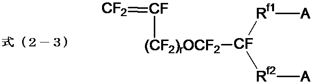
- イオン交換膜の製造に使用する、請求項1~7のいずれか1項に記載のペレットの製造方法。
- イオン交換基に変換できる基を有する含フッ素ポリマーを含み、
前記含フッ素ポリマーのイオン交換基に変換できる基をイオン交換基に変換した際の含フッ素ポリマーのイオン交換容量が、1.1ミリ当量/グラム乾燥樹脂以上であり、
光線透過率が30~60%であることを特徴とするペレット。 - 前記イオン交換基に変換できる基が、カルボン酸型官能基に変換できる基又はスルホン酸型官能基に変換できる基である、請求項9に記載のペレット。
- イオン交換膜の製造に使用する、請求項9又は10に記載のペレット。
- 請求項9~11のいずれか1項に記載のペレットを用いて形成されるイオン交換膜。
- 膜厚が、30~180μmである、請求項12に記載のイオン交換膜。
- 塩化アルカリ水溶液の電解に使用される請求項12又は13に記載のイオン交換膜。
Priority Applications (5)
| Application Number | Priority Date | Filing Date | Title |
|---|---|---|---|
| CN201980059872.6A CN112689554B (zh) | 2018-09-14 | 2019-09-11 | 粒料的制造方法、粒料及离子交换膜 |
| JP2020546059A JP7298619B2 (ja) | 2018-09-14 | 2019-09-11 | ペレットの製造方法、ペレット及びイオン交換膜 |
| US17/194,998 US12378338B2 (en) | 2018-09-14 | 2021-03-08 | Method for producing pellets |
| JP2023070829A JP7601136B2 (ja) | 2018-09-14 | 2023-04-24 | ペレットの製造方法、ペレット及びイオン交換膜 |
| US19/226,922 US20250289918A1 (en) | 2018-09-14 | 2025-06-03 | Method for producing pellets, pellets and ion exchange film |
Applications Claiming Priority (2)
| Application Number | Priority Date | Filing Date | Title |
|---|---|---|---|
| JP2018172344 | 2018-09-14 | ||
| JP2018-172344 | 2018-09-14 |
Related Child Applications (1)
| Application Number | Title | Priority Date | Filing Date |
|---|---|---|---|
| US17/194,998 Continuation US12378338B2 (en) | 2018-09-14 | 2021-03-08 | Method for producing pellets |
Publications (1)
| Publication Number | Publication Date |
|---|---|
| WO2020054777A1 true WO2020054777A1 (ja) | 2020-03-19 |
Family
ID=69778393
Family Applications (1)
| Application Number | Title | Priority Date | Filing Date |
|---|---|---|---|
| PCT/JP2019/035752 Ceased WO2020054777A1 (ja) | 2018-09-14 | 2019-09-11 | ペレットの製造方法、ペレット及びイオン交換膜 |
Country Status (4)
| Country | Link |
|---|---|
| US (2) | US12378338B2 (ja) |
| JP (2) | JP7298619B2 (ja) |
| CN (1) | CN112689554B (ja) |
| WO (1) | WO2020054777A1 (ja) |
Cited By (1)
| Publication number | Priority date | Publication date | Assignee | Title |
|---|---|---|---|---|
| JP2021181539A (ja) * | 2020-05-19 | 2021-11-25 | Agcエンジニアリング株式会社 | 複合粒子、成形体、中空糸膜の製造方法、イオン交換膜の製造方法 |
Families Citing this family (1)
| Publication number | Priority date | Publication date | Assignee | Title |
|---|---|---|---|---|
| WO2025110152A1 (ja) * | 2023-11-22 | 2025-05-30 | Agc株式会社 | ペレットの製造方法、イオン交換膜の製造方法及びペレット |
Citations (2)
| Publication number | Priority date | Publication date | Assignee | Title |
|---|---|---|---|---|
| WO2010147176A1 (ja) * | 2009-06-17 | 2010-12-23 | 東レ株式会社 | 結晶化ポリエステルの製造方法 |
| WO2013115072A1 (ja) * | 2012-01-31 | 2013-08-08 | 旭硝子株式会社 | 含フッ素イオン交換樹脂液の製造方法 |
Family Cites Families (30)
| Publication number | Priority date | Publication date | Assignee | Title |
|---|---|---|---|---|
| NL150372B (nl) * | 1967-05-23 | 1976-08-16 | Akzo Nv | Inrichting voor het continu vervaardigen van kunststof profielen. |
| GB1443109A (en) * | 1973-06-30 | 1976-07-21 | Toyo Boseki | Film having excellent slip characterisitcs and its production |
| JPS58113225A (ja) * | 1981-12-28 | 1983-07-06 | Asahi Glass Co Ltd | イオン交換膜の加工法 |
| CA1232260A (en) * | 1984-02-22 | 1988-02-02 | Shuichi Sugimori | Porous water-treating material and process for producing the same |
| CA1300776C (en) * | 1987-06-04 | 1992-05-12 | Masahiro Hotta | Moldable block copolymer resin composition |
| MX9205262A (es) * | 1991-09-19 | 1993-08-01 | Goodrich Co B F | Metodo mejorado para la extrusion de compuestos pulverizados de pvc. |
| JPH071447A (ja) * | 1993-06-21 | 1995-01-06 | Toray Ind Inc | ポリエステルのペレット、およびその製造方法 |
| GB9317967D0 (en) * | 1993-08-28 | 1993-10-13 | Landbrent Ltd | Improvements relating to plasics articles |
| DE10004688A1 (de) * | 1999-02-03 | 2000-10-05 | Manfred Butsch | Kunststoffgranulatsichter |
| JP4415481B2 (ja) * | 1999-11-04 | 2010-02-17 | パナソニック電工株式会社 | 光電変換素子及びその製造方法 |
| JP4192628B2 (ja) * | 2003-02-27 | 2008-12-10 | 東ソー株式会社 | エチレン系共重合体ペレット |
| GB2404662A (en) * | 2003-08-01 | 2005-02-09 | Reckitt Benckiser | Cleaning composition |
| JP5256459B2 (ja) * | 2006-09-29 | 2013-08-07 | Dowaエレクトロニクス株式会社 | 透明導電膜及びその製造方法 |
| CN101020758B (zh) * | 2007-02-25 | 2010-05-19 | 山东东岳神舟新材料有限公司 | 一种聚合物离子交换膜及其制备方法 |
| CN101293411A (zh) * | 2007-04-27 | 2008-10-29 | 阎家骥 | 多层共挤cpp增韧基材膜及其生产工艺 |
| US20080315453A1 (en) | 2007-06-22 | 2008-12-25 | Michael Joseph Molitor | Process for the production of polyester nanocomposites |
| JP2010172947A (ja) * | 2009-01-30 | 2010-08-12 | Toyota Motor Corp | 超高温熱間鍛造方法 |
| CN102325926B (zh) * | 2009-02-23 | 2014-09-17 | 旭硝子株式会社 | 阳离子交换膜及其制造方法、以及使用其的电解槽 |
| CN101693215B (zh) * | 2009-10-26 | 2010-12-29 | 山东东岳神舟新材料有限公司 | 低离子交换容量氟树脂制备及应用 |
| CN102152427A (zh) * | 2010-11-09 | 2011-08-17 | 金发科技股份有限公司 | 一种热切造粒风送冷却系统 |
| CN102601885A (zh) * | 2012-03-20 | 2012-07-25 | 江苏景宏新材料科技有限公司 | 一种纵横纵拉伸强化锂离子电池隔膜的制备工艺 |
| CN102581979A (zh) * | 2012-03-26 | 2012-07-18 | 江苏锵尼玛新材料有限公司 | 超高分子量聚乙烯冻胶颗粒的制备方法及其应用 |
| CN103087410B (zh) * | 2013-01-16 | 2017-06-20 | 合肥杰事杰新材料股份有限公司 | 一种聚丙烯微孔电池膜及其制备方法 |
| WO2017043590A1 (ja) * | 2015-09-08 | 2017-03-16 | 旭硝子株式会社 | 塩化アルカリ電解用イオン交換膜の製造方法および塩化アルカリ電解装置の製造方法 |
| WO2017086465A1 (ja) * | 2015-11-20 | 2017-05-26 | 旭硝子株式会社 | ヨウ素原子含有量の低減された含フッ素化合物を製造する方法 |
| JPWO2017154925A1 (ja) * | 2016-03-08 | 2019-01-10 | Agc株式会社 | イオン交換膜、その製造方法および塩化アルカリ電解装置 |
| CN105694222A (zh) * | 2016-03-22 | 2016-06-22 | 日丰企业集团有限公司 | 低表面粗糙度pp-r管材及其制备方法 |
| JP7015116B2 (ja) * | 2016-06-29 | 2022-02-15 | 旭化成株式会社 | メタクリル系樹脂組成物、該メタクリル系樹脂組成物の製造方法、ペレット、及び成形体 |
| CN106125172B (zh) * | 2016-08-10 | 2018-09-21 | 张家港康得新光电材料有限公司 | 一种扩散膜及其制作方法 |
| CN107383736A (zh) * | 2017-09-04 | 2017-11-24 | 清远市恒晟塑料制粒有限公司 | 一种塑料制粒工艺 |
-
2019
- 2019-09-11 CN CN201980059872.6A patent/CN112689554B/zh active Active
- 2019-09-11 WO PCT/JP2019/035752 patent/WO2020054777A1/ja not_active Ceased
- 2019-09-11 JP JP2020546059A patent/JP7298619B2/ja active Active
-
2021
- 2021-03-08 US US17/194,998 patent/US12378338B2/en active Active
-
2023
- 2023-04-24 JP JP2023070829A patent/JP7601136B2/ja active Active
-
2025
- 2025-06-03 US US19/226,922 patent/US20250289918A1/en active Pending
Patent Citations (2)
| Publication number | Priority date | Publication date | Assignee | Title |
|---|---|---|---|---|
| WO2010147176A1 (ja) * | 2009-06-17 | 2010-12-23 | 東レ株式会社 | 結晶化ポリエステルの製造方法 |
| WO2013115072A1 (ja) * | 2012-01-31 | 2013-08-08 | 旭硝子株式会社 | 含フッ素イオン交換樹脂液の製造方法 |
Cited By (2)
| Publication number | Priority date | Publication date | Assignee | Title |
|---|---|---|---|---|
| JP2021181539A (ja) * | 2020-05-19 | 2021-11-25 | Agcエンジニアリング株式会社 | 複合粒子、成形体、中空糸膜の製造方法、イオン交換膜の製造方法 |
| JP7549973B2 (ja) | 2020-05-19 | 2024-09-12 | Agcエンジニアリング株式会社 | 複合粒子、成形体、中空糸膜の製造方法、イオン交換膜の製造方法 |
Also Published As
| Publication number | Publication date |
|---|---|
| JP7298619B2 (ja) | 2023-06-27 |
| CN112689554A (zh) | 2021-04-20 |
| JP7601136B2 (ja) | 2024-12-17 |
| JP2023083531A (ja) | 2023-06-15 |
| US20250289918A1 (en) | 2025-09-18 |
| JPWO2020054777A1 (ja) | 2021-09-16 |
| US12378338B2 (en) | 2025-08-05 |
| US20210198397A1 (en) | 2021-07-01 |
| CN112689554B (zh) | 2023-05-16 |
Similar Documents
| Publication | Publication Date | Title |
|---|---|---|
| JP7384036B2 (ja) | 固体高分子電解質膜、膜電極接合体および水電解装置 | |
| JP7414018B2 (ja) | 膜電極接合体、水電解装置 | |
| US20250289918A1 (en) | Method for producing pellets, pellets and ion exchange film | |
| KR101962061B1 (ko) | 이온 교환막 | |
| CN109072463B (zh) | 碱金属氯化物电解用离子交换膜、其制造方法、及碱金属氯化物电解装置 | |
| CN107949664A (zh) | 碱金属氯化物电解用离子交换膜的制造方法以及碱金属氯化物电解装置的制造方法 | |
| US20220396890A1 (en) | Ion exchange membrane with catalyst layer, ion exchange membrane and electrolytic hydrogenation apparatus | |
| JP6586961B2 (ja) | 塩化アルカリ電解用イオン交換膜、製造方法、及び塩化アルカリ電解装置 | |
| JP7746994B2 (ja) | 膜電極接合体、固体高分子電解質膜、水電解装置および電解水素化装置 | |
| CN107531925B (zh) | 离子交换膜 | |
| KR101950130B1 (ko) | 이온 교환막 | |
| WO2016027862A1 (ja) | 塩化アルカリ電解用イオン交換膜および塩化アルカリ電解装置 | |
| JP6927191B2 (ja) | 塩化アルカリ電解用イオン交換膜、塩化アルカリ電解用イオン交換膜の製造方法および塩化アルカリ電解装置 | |
| JP7040642B2 (ja) | 複合粒子およびイオン交換膜の製造方法 | |
| JP7838485B2 (ja) | 電解質膜、電解装置およびレドックスフロー電池 | |
| JP6638724B2 (ja) | 塩化アルカリ電解用イオン交換膜および塩化アルカリ電解装置 | |
| WO2025110152A1 (ja) | ペレットの製造方法、イオン交換膜の製造方法及びペレット |
Legal Events
| Date | Code | Title | Description |
|---|---|---|---|
| 121 | Ep: the epo has been informed by wipo that ep was designated in this application |
Ref document number: 19861037 Country of ref document: EP Kind code of ref document: A1 |
|
| ENP | Entry into the national phase |
Ref document number: 2020546059 Country of ref document: JP Kind code of ref document: A |
|
| NENP | Non-entry into the national phase |
Ref country code: DE |
|
| 122 | Ep: pct application non-entry in european phase |
Ref document number: 19861037 Country of ref document: EP Kind code of ref document: A1 |