WO2020045144A1 - Disjoncteur, circuit de sécurité et bloc-batterie secondaire - Google Patents
Disjoncteur, circuit de sécurité et bloc-batterie secondaire Download PDFInfo
- Publication number
- WO2020045144A1 WO2020045144A1 PCT/JP2019/032269 JP2019032269W WO2020045144A1 WO 2020045144 A1 WO2020045144 A1 WO 2020045144A1 JP 2019032269 W JP2019032269 W JP 2019032269W WO 2020045144 A1 WO2020045144 A1 WO 2020045144A1
- Authority
- WO
- WIPO (PCT)
- Prior art keywords
- resin case
- fixing surface
- piece
- breaker
- movable
- Prior art date
Links
Images


Classifications
-
- H—ELECTRICITY
- H01—ELECTRIC ELEMENTS
- H01M—PROCESSES OR MEANS, e.g. BATTERIES, FOR THE DIRECT CONVERSION OF CHEMICAL ENERGY INTO ELECTRICAL ENERGY
- H01M50/00—Constructional details or processes of manufacture of the non-active parts of electrochemical cells other than fuel cells, e.g. hybrid cells
- H01M50/50—Current conducting connections for cells or batteries
- H01M50/572—Means for preventing undesired use or discharge
- H01M50/574—Devices or arrangements for the interruption of current
- H01M50/581—Devices or arrangements for the interruption of current in response to temperature
-
- H—ELECTRICITY
- H01—ELECTRIC ELEMENTS
- H01H—ELECTRIC SWITCHES; RELAYS; SELECTORS; EMERGENCY PROTECTIVE DEVICES
- H01H37/00—Thermally-actuated switches
- H01H37/02—Details
- H01H37/32—Thermally-sensitive members
- H01H37/52—Thermally-sensitive members actuated due to deflection of bimetallic element
- H01H37/54—Thermally-sensitive members actuated due to deflection of bimetallic element wherein the bimetallic element is inherently snap acting
-
- H—ELECTRICITY
- H01—ELECTRIC ELEMENTS
- H01H—ELECTRIC SWITCHES; RELAYS; SELECTORS; EMERGENCY PROTECTIVE DEVICES
- H01H37/00—Thermally-actuated switches
- H01H37/02—Details
- H01H37/64—Contacts
-
- H—ELECTRICITY
- H01—ELECTRIC ELEMENTS
- H01M—PROCESSES OR MEANS, e.g. BATTERIES, FOR THE DIRECT CONVERSION OF CHEMICAL ENERGY INTO ELECTRICAL ENERGY
- H01M10/00—Secondary cells; Manufacture thereof
- H01M10/42—Methods or arrangements for servicing or maintenance of secondary cells or secondary half-cells
- H01M10/425—Structural combination with electronic components, e.g. electronic circuits integrated to the outside of the casing
-
- H—ELECTRICITY
- H01—ELECTRIC ELEMENTS
- H01H—ELECTRIC SWITCHES; RELAYS; SELECTORS; EMERGENCY PROTECTIVE DEVICES
- H01H2205/00—Movable contacts
- H01H2205/002—Movable contacts fixed to operating part
-
- H—ELECTRICITY
- H01—ELECTRIC ELEMENTS
- H01H—ELECTRIC SWITCHES; RELAYS; SELECTORS; EMERGENCY PROTECTIVE DEVICES
- H01H37/00—Thermally-actuated switches
- H01H37/02—Details
- H01H37/32—Thermally-sensitive members
- H01H37/52—Thermally-sensitive members actuated due to deflection of bimetallic element
- H01H37/54—Thermally-sensitive members actuated due to deflection of bimetallic element wherein the bimetallic element is inherently snap acting
- H01H37/5427—Thermally-sensitive members actuated due to deflection of bimetallic element wherein the bimetallic element is inherently snap acting encapsulated in sealed miniaturised housing
- H01H37/5436—Thermally-sensitive members actuated due to deflection of bimetallic element wherein the bimetallic element is inherently snap acting encapsulated in sealed miniaturised housing mounted on controlled apparatus
-
- H—ELECTRICITY
- H01—ELECTRIC ELEMENTS
- H01M—PROCESSES OR MEANS, e.g. BATTERIES, FOR THE DIRECT CONVERSION OF CHEMICAL ENERGY INTO ELECTRICAL ENERGY
- H01M2200/00—Safety devices for primary or secondary batteries
- H01M2200/10—Temperature sensitive devices
- H01M2200/101—Bimetal
-
- H—ELECTRICITY
- H01—ELECTRIC ELEMENTS
- H01M—PROCESSES OR MEANS, e.g. BATTERIES, FOR THE DIRECT CONVERSION OF CHEMICAL ENERGY INTO ELECTRICAL ENERGY
- H01M2200/00—Safety devices for primary or secondary batteries
- H01M2200/10—Temperature sensitive devices
- H01M2200/106—PTC
-
- Y—GENERAL TAGGING OF NEW TECHNOLOGICAL DEVELOPMENTS; GENERAL TAGGING OF CROSS-SECTIONAL TECHNOLOGIES SPANNING OVER SEVERAL SECTIONS OF THE IPC; TECHNICAL SUBJECTS COVERED BY FORMER USPC CROSS-REFERENCE ART COLLECTIONS [XRACs] AND DIGESTS
- Y02—TECHNOLOGIES OR APPLICATIONS FOR MITIGATION OR ADAPTATION AGAINST CLIMATE CHANGE
- Y02E—REDUCTION OF GREENHOUSE GAS [GHG] EMISSIONS, RELATED TO ENERGY GENERATION, TRANSMISSION OR DISTRIBUTION
- Y02E60/00—Enabling technologies; Technologies with a potential or indirect contribution to GHG emissions mitigation
- Y02E60/10—Energy storage using batteries
Definitions
- the present invention relates to a small breaker or the like suitable for use in a safety circuit of an electric device.
- breakers have been used as protection devices (safety circuits) for secondary batteries, motors, and the like of various electrical devices.
- the breaker is activated when the temperature of the secondary battery during charging / discharging rises excessively, or when an abnormal condition occurs, such as when an overcurrent flows through a motor or the like provided in a device such as an automobile or a home appliance. Cut off the current to protect the secondary battery and motor.
- the breaker used as such a protection device operates accurately (has good temperature characteristics) in accordance with the temperature change and has a stable resistance value when energized in order to ensure the safety of the equipment. Is required.
- Patent Literature 1 discloses a breaker to which a bimetal is applied as a thermally responsive element.
- a bimetal is an element in which two types of plate-like metal materials having different coefficients of thermal expansion are laminated, and the shape of the metal material is changed according to a temperature change to control the conduction state of the contact.
- the breaker disclosed in the document has components such as a fixed piece, a movable piece, a thermo-responsive element, and a PTC thermistor housed in a case, and terminals of the fixed piece and the movable piece protrude from the case, and the electric device of the electric device is electrically operated. Used connected to the circuit.
- the breaker when used as a protective device such as a secondary battery mounted on an electric device such as a notebook personal computer, a tablet-type portable information terminal device, or a thin multi-functional mobile phone called a smartphone, In addition to ensuring safety, miniaturization is required.
- portable information terminal devices have a strong desire to reduce the size (thinness) of devices, and devices newly released by each company are designed to be small in order to ensure superiority in design. The tendency to be noticeable.
- a breaker mounted together with a secondary battery is also required to be further reduced in size.
- the movable piece, the thermoresponsive element, and the PTC thermistor are housed through an opening provided in the case body.
- a lid member is attached to the opening of the case main body in which the movable piece, the thermoresponsive element, and the PTC thermistor are housed, and the first fixing surface of the case main body and the second fixing surface of the lid member are fixed by ultrasonic welding or the like. (See paragraph (0032) of the same document).
- the second fixing surface has a rib-like projection in a region slightly inside the outer edge of the lid member, and a projection extending continuously along the outer edge.
- the lid member bends during ultrasonic welding, the pressure acting on the top of the protruding portion decreases, and the gap between the first fixing surface and the second fixing surface is good. And the rigidity and strength of the case may be insufficient.
- the present invention has been made in order to solve the above-described problems, and has as its main object to provide a breaker that can obtain good rigidity and strength of a case even in a breaker that is extremely small.
- a first invention of the present invention has a fixed contact, an elastic portion formed in a plate shape and elastically deformed, and a movable contact at one end of the elastic portion, wherein the movable contact is fixed.
- the movable piece is pressed from and brought into contact with the contact, and is deformed with a change in temperature, so that the state of the movable piece is separated from the fixed contact from the conductive state in which the movable contact contacts the fixed contact.
- a thermally responsive element for shifting to a shut-off state a first resin case having an opening for accommodating the movable piece and the thermally responsive element, and a second resin case mounted on the first to close the opening And a plate-shaped cover piece embedded in the second resin case, wherein the first resin case has a first fixing surface fixed to the second resin case in the opening. Continuously formed around A second fixing surface fixed to the first resin case is formed on the second resin case so as to face the first fixing surface, and the second fixing surface is formed on the second fixing case. A protrusion protruding toward a surface is formed, and the protrusion and the cover piece overlap at least partially in a plan view as viewed from a thickness direction of the cover piece. .
- a movable contact having a fixed contact, an elastic portion formed in a plate shape and elastically deforming, and a movable contact at one end of the elastic portion, wherein the movable contact is pressed against the fixed contact to make contact therewith.
- a thermally responsive element that changes the state of the movable piece from a conductive state in which the movable contact contacts the fixed contact to an interrupted state in which the movable contact is separated from the fixed contact by deforming with the temperature change
- a first resin case having an opening for accommodating the movable piece and the thermoresponsive element, a second resin case mounted first to close the opening, and a second resin case.
- a breaker provided with a buried plate-shaped cover piece, wherein the first resin case has a first fixing surface fixed to the second resin case formed continuously around the opening;
- a second fixing surface fixed to the first resin case is formed continuously facing the first fixing surface, and the first fixing surface has a protrusion protruding toward the second fixing surface.
- the protrusion is formed, and the cover piece overlaps at least partially in a plan view as viewed from the thickness direction of the cover piece.
- the opening includes a rectangular region formed in a rectangular shape in the plan view, and the projecting portion and the cover piece are located outside four corners of the rectangular region in the plan view. It is desirable that they overlap in adjacent regions.
- the second resin case is formed in a rectangular shape that is long in a longitudinal direction of the movable piece in the plan view, and the protruding portion is formed along a length of the second resin case along the opening. It is desirable to have a first portion that extends linearly in parallel with the side, and a second portion that is continuous from the first portion and that is bent inward in the short direction of the movable piece in the adjacent region.
- the second portion and the cover piece overlap in the plan view.
- the projecting portion may be continuous with the second portion, provided inward in the shorter direction than the first portion, and extend linearly in parallel with the first portion. Desirably, it further has three parts.
- a safety circuit for an electric device according to the present invention is provided with the breaker.
- a secondary battery circuit according to the present invention is provided with the breaker.
- the first fixing surface is formed continuously around the opening in the first resin case, and the second fixing surface is opposed to the first fixing surface in the second resin case. And are formed continuously.
- the protruding portion formed on the second fixing surface and protruding toward the first fixing surface is melted at the time of ultrasonic welding, thereby improving the fixing between the first fixing surface and the second fixing surface.
- the plate-like cover piece embedded in the second resin case suppresses the bending of the second resin case during ultrasonic welding.
- the projecting portion and the cover piece overlap at least partially in plan view, a decrease in pressure acting on the top of the projecting portion is suppressed, and the first fixing surface and the second fixing surface Even better fixation is obtained between the surfaces.
- the first resin case has the first fixing surface formed continuously around the opening, and the second resin case has the second fixing surface facing the first fixing surface. And are formed continuously.
- the protruding portion formed on the first fixing surface and protruding toward the second fixing surface is melted at the time of ultrasonic welding, thereby improving the fixing between the first fixing surface and the second fixing surface.
- the plate-like cover piece embedded in the second resin case suppresses the bending of the second resin case during ultrasonic welding. Furthermore, in the second invention, since the projecting portion and the cover piece overlap at least partially in plan view, a decrease in pressure acting on the top of the projecting portion is suppressed, and the first fixing surface and the second fixing surface Even better fixation is obtained between the surfaces.
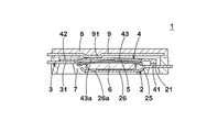
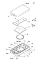
- FIG. 2 is a perspective view showing a schematic configuration of the breaker according to the first embodiment of the present invention before assembly.
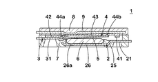
- Sectional drawing which shows the said breaker in a normal charge or discharge state.
- Sectional drawing which shows the said breaker in an overcharge state or at the time of abnormality.
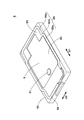
- the perspective view of the lid member which comprises the said breaker.
- Sectional drawing of the welding part of the case main body and lid member which comprise the said breaker.
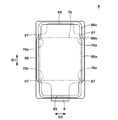
- the bottom view of the said cover member The perspective view before assembling which shows the schematic structure of the breaker by one Embodiment of this 2nd invention.
- the top view of the breaker of FIG. The top view which shows the structure of the secondary battery pack provided with the said breaker of this invention.
- the circuit diagram of the safety circuit provided with the above-mentioned breaker of the present invention.
- FIGS. 1 and 3 show the configuration of the breaker.
- the breaker 1 includes a pair of terminals 22 and 32 that are partially exposed from the case 10 to the outside.
- the terminals 22 and 32 are electrically connected to an external circuit (not shown)
- the breaker 1 forms a main part of a safety circuit of the electric device.
- the breaker 1 has a first terminal piece (fixed piece) 2 having a fixed contact 21 and a terminal 22, a second terminal piece 3 having a terminal 32, and a movable contact 41 at a tip portion.
- It is constituted by a case 10 for accommodating the PTC thermistor 6 and the like.
- the case 10 includes a case body (first resin case) 7, a lid member (second resin case) 8 mounted on the upper surface of the case body 7, and the like.
- the first terminal piece 2 is formed, for example, by pressing a metal plate containing copper or the like as a main component (other metal plate such as a copper-titanium alloy, nickel silver, brass, etc.), and is inserted into the case body 7. Embedded by molding.
- the fixed contact 21 is formed by cladding, plating, coating, or the like of a material having good conductivity, such as silver, nickel, a nickel-silver alloy, a copper-silver alloy, or a gold-silver alloy.
- the fixed contact 21 is formed at a position facing the movable contact 41 in the first terminal piece 2, and is exposed to the housing recess 73 of the case body 7 from a part of an opening 73 a formed inside the case body 7. ing.
- the fixed contact 21 and the terminal 22 are arranged at different heights by a step bent portion (not shown) embedded in the case body 7.
- the surface of the first terminal strip 2 on which the fixed contact 21 is formed ie, the upper surface in FIG. 1 is the first surface, and the opposite bottom surface is the first surface. It is described as two surfaces. The same applies to other components, for example, the second terminal piece 3, the movable piece 4, the thermally responsive element 5, the PTC thermistor 6, the case 10, the cover piece 9, and the like.
- the second surface of the terminal 22 is exposed in a rectangular shape (not shown) from the bottom wall of the case body 7 and is connected to an external circuit by a method such as soldering.
- a pair of terminals 22 are arranged in parallel in the short direction of the breaker 1.
- the first terminal piece 2 has a step bent portion 25 bent in a step shape (a crank shape in a side view) and a support portion 26 that supports the PTC thermistor 6.
- the step bending portion 25 connects the fixed contact 21 and the support portion 26, and arranges the fixed contact 21 and the support portion 26 at different heights.
- the PTC thermistor 6 is mounted on three projections (doughs) 26 a formed on the support portion 26 at three places, and is supported by the projections 26 a.
- the second terminal piece 3 is formed by pressing a metal plate mainly composed of copper or the like, similarly to the first terminal piece 2, and is embedded in the case body 7 by insert molding.
- the second terminal piece 3 has a joint portion 31 joined to the movable piece 4 and a terminal 32.
- the joining portion 31 and the terminal 32 are arranged at different heights by a step bent portion (not shown) embedded in the case body 7.
- the joint 31 is exposed to the housing recess 73 of the case body 7 from a part of the opening 73 b formed inside the case body 7, and is electrically connected to the movable piece 4.
- the second surface of the terminal 32 is exposed in a rectangular shape (not shown) from the bottom wall of the case body 7 and is connected to an external circuit by a method such as soldering.
- a pair of terminals 32 are arranged in the short direction of the breaker 1.
- the movable piece 4 is formed in a plate shape by pressing a metal material mainly containing copper or the like.
- the movable piece 4 is formed in an arm shape symmetric with respect to a longitudinal center line.
- a movable contact 41 is formed at one end of the movable piece 4.
- the movable contact 41 is formed on the second surface of the movable piece 4 using the same material as that of the fixed contact 21 and is joined to the tip of the movable piece 4 by a method such as welding, cladding, or crimping.
- a joint 42 that is electrically connected to the joint 31 of the second terminal piece 3 is formed.
- the first surface of the joint 31 of the second terminal piece 3 and the second surface of the joint 42 of the movable piece 4 are fixed by, for example, laser welding.
- Laser welding is a welding method in which a work (in the present embodiment, the second terminal piece 3 and the movable piece 4 are equivalent) is irradiated with laser light, and the works are locally melted and solidified to join the works together. is there.
- a laser welding mark different in form from a welding mark formed by another welding method for example, resistance welding using Joule heat
- the movable piece 4 has an elastic portion 43 between the movable contact 41 and the joint 42.
- the elastic part 43 extends from the joint part 42 to the movable contact 41 side.
- the joint portion 42 is provided on the opposite side of the movable contact 41 with the elastic portion 43 interposed therebetween.
- the movable piece 4 is fixed by being fixed to the joint part 31 of the second terminal piece 3 at the joint part 42, and the movable contact 41 formed at the tip of the movable part 4 is fixed by the elastic part 43 being elastically deformed. And the first terminal piece 2 and the movable piece 4 can be energized. Since the movable piece 4 and the second terminal piece 3 are electrically connected at the joints 31 and 42, the first terminal piece 2 and the second terminal piece 3 can be electrically connected.
- the movable piece 4 is curved or bent in the elastic portion 43 by press working.
- the degree of bending or bending is not particularly limited as long as the thermoresponsive element 5 can be accommodated, and may be appropriately set in consideration of the elastic force at the operating temperature and the return temperature, the pressing force of the contact, and the like.
- a pair of protrusions (contact portions) 44 a and 44 b are formed on the second surface of the elastic portion 43 so as to face the thermally responsive element 5.
- the protrusions 44a, 44b and the thermally responsive element 5 come into contact with each other, and the deformation of the thermally responsive element 5 is transmitted to the elastic portion 43 via the protrusions 44a, 44b (see FIGS. 1 and 3).
- the thermally responsive element 5 changes the state of the movable piece 4 from a conduction state in which the movable contact 41 contacts the fixed contact 21 to a cutoff state in which the movable contact 41 is separated from the fixed contact 21.
- the thermally responsive element 5 has an initial shape curved in an arc shape and is formed by laminating thin plates having different coefficients of thermal expansion. When the operating temperature is reached due to overheating, the curved shape of the thermally responsive element 5 reversely warps with snap motion, and is restored when the temperature falls below the return temperature due to cooling.
- the initial shape of the thermoresponsive element 5 can be formed by press working.
- the material and shape of the thermally responsive element 5 are not particularly limited as long as the elastic portion 43 of the movable piece 4 is pushed up by the reverse warp operation of the thermally responsive element 5 at the desired temperature and is restored by the elastic force of the elastic portion 43.
- a rectangular shape is desirable from the viewpoint of productivity and efficiency of the reverse warpage operation, and a rectangular shape is desirable in order to efficiently push up the elastic portion 43 while being small.
- the thermal response element 5 may be made of, for example, copper-nickel-manganese alloy or nickel-chromium-iron alloy on the high expansion side and iron-nickel alloy on the low expansion side, such as nickel silver, brass, and stainless steel. Two kinds of materials having different coefficients of thermal expansion made of various alloys such as steel are laminated and used in combination according to required conditions.
- the PTC thermistor 6 conducts the first terminal piece 2 and the movable piece 4 when the movable piece 4 is in the cutoff state.
- the PTC thermistor 6 is disposed between the support 26 of the first terminal piece 2 and the thermoresponsive element 5. That is, the support portion 26 is located directly below the thermally responsive element 5 with the PTC thermistor 6 interposed therebetween.
- the current flowing through the PTC thermistor 6 increases. If the PTC thermistor 6 is a PTC thermistor whose resistance value increases with increasing temperature to limit the current, the type of the operating current, operating voltage, operating temperature, return temperature, etc.
- a ceramic sintered body containing barium titanate, strontium titanate, or calcium titanate is used.
- a so-called polymer PTC in which a polymer contains conductive particles such as carbon may be used.
- the case body 7 and the lid member 8 constituting the case 10 are molded from a thermoplastic resin such as flame-retardant polyamide, polyphenylene sulfide (PPS), liquid crystal polymer (LCP), and polybutylene terephthalate (PBT) having excellent heat resistance.
- a thermoplastic resin such as flame-retardant polyamide, polyphenylene sulfide (PPS), liquid crystal polymer (LCP), and polybutylene terephthalate (PBT) having excellent heat resistance.
- PPS polyphenylene sulfide
- LCP liquid crystal polymer
- PBT polybutylene terephthalate
- a housing recess 73 is formed in the case body 7 as an internal space for housing the movable piece 4, the thermally responsive element 5, the PTC thermistor 6, and the like.
- the accommodation recess 73 has openings 73a and 73b for accommodating the movable piece 4, an opening 73c for accommodating the movable piece 4 and the thermally responsive element 5, an opening 73d for accommodating the PTC thermistor 6, and the like. are doing.
- the edges of the movable piece 4 and the thermally responsive element 5 incorporated in the case body 7 are respectively abutted by frames (inner walls) formed inside the housing recess 73, and when the thermally responsive element 5 is reversely warped. You will be guided.
- a cover piece 9 is embedded in the lid member 8 by insert molding.
- the cover piece 9 is formed in a plate shape by pressing the above-described metal containing copper or the like as a main component or a metal such as stainless steel.
- the cover piece 9 appropriately contacts the first surface of the movable piece 4 to regulate the movement of the movable piece 4, and furthermore, the rigidity of the cover member 8 and thus the case 10 as a housing. -Contribute to the downsizing of the breaker 1 while increasing the strength.
- the openings 73a, 73b, 73c and the like of the case main body 7 containing the first terminal piece 2, the second terminal piece 3, the movable piece 4, the thermal response element 5, the PTC thermistor 6, and the like are closed.
- the lid member 8 is attached to the case main body 7.
- the case body 7 and the lid member 8 are joined by, for example, ultrasonic welding.
- the case body 7 and the lid member 8 are continuously joined over the entire periphery of the respective outer edges, and the airtightness of the case 10 is improved.
- the internal space of the case 10 provided by the housing recess 73 is sealed, and components such as the movable piece 4, the thermally responsive element 5, and the PTC thermistor 6 can be shielded from the atmosphere outside the case 10 and protected.
- the resin is entirely disposed on the first surface side of the cover piece 9, the airtightness of the housing recess 73 is further enhanced.
- FIG. 2 shows the operation of the breaker 1 in a normal charge or discharge state.
- the thermally responsive element 5 maintains an initial shape that is convex toward the elastic portion 43 (before reverse warpage).
- the cover piece 9 is provided with a protrusion 91 that contacts the top 43 a of the movable piece 4 and presses the top 43 a toward the thermally responsive element 5.
- the elastic portion 43 is elastically deformed by the pressing of the top portion 43 a by the protruding portion 91, and the movable contact 41 formed at the tip thereof is pressed against the fixed contact 21 and comes into contact therewith.
- the first terminal piece 2 and the second terminal piece 3 of the breaker 1 are electrically connected through the elastic portion 43 of the movable piece 4 and the like.
- the elastic portion 43 of the movable piece 4 comes into contact with the thermally responsive element 5, and the movable piece 4, the thermally responsive element 5, the PTC thermistor 6, and the first terminal piece 2 may be electrically connected as a circuit.
- the resistance of the PTC thermistor 6 is overwhelmingly greater than the resistance of the movable piece 4, the current flowing through the PTC thermistor 6 is substantially smaller than the amount flowing through the fixed contact 21 and the movable contact 41. It is negligible.
- FIG. 3 shows an operation of the breaker 1 in an overcharged state or an abnormal state.
- the thermoresponsive element 5 that has reached the operating temperature reversely warps, the elastic portion 43 of the movable piece 4 is pushed up, and the fixed contact 21 and the movable contact 41 are separated.
- the operating temperature of the thermoresponsive element 5 when the movable piece 4 is pushed up when the thermoresponsive element 5 is deformed inside the breaker 1 is, for example, 70 ° C. to 90 ° C.
- the current flowing between the fixed contact 21 and the movable contact 41 is cut off, and a slight leakage current flows through the thermoresponsive element 5 and the PTC thermistor 6.
- the PTC thermistor 6 continues to generate heat as long as such a leakage current flows and sharply increases the resistance value while maintaining the thermally responsive element 5 in a reverse warp state, so that the current flows through the path between the fixed contact 21 and the movable contact 41. , And only the slight leakage current described above exists (constituting a self-holding circuit). This leakage current can be used for other functions of the safety device.
- the contact between the top 43a and the protrusion 91 is maintained even in a situation where the thermally responsive element 5 that has reached the operating temperature undergoes a reverse warp deformation.
- the movable piece 4 is pushed up with the contact point between the top 43a and the protrusion 91 serving as a fulcrum, and the distance between the fixed contact 21 and the movable contact 41 is easily maintained.
- the movable piece 4 is supported by the protruding portion 91 and the protruding portion 91 bears a part of the pushing-up force of the thermally responsive element 5, the force applied to the joint 42 of the movable piece 4 is suppressed, and the joint 31 The peeling of the joint 42 from the surface is suppressed.
- the case body 7 has a first fixing surface 75 that is fixed to the lid member 8.
- the first fixing surface 75 is formed continuously around the openings 73a, 73b and 73c.
- the first fixing surface 75 is formed along the outer edge of the case body 7 so as to be continuous over the entire circumference of the case body 7.
- FIG. 4 is a perspective view of the lid member 8 viewed from the second surface side facing the movable piece 4.
- the cover member 8 has an opening 83 for exposing the cover piece 9 to the internal space of the case 10 and a second fixing surface 85 fixed to the case body 7.
- the opening 83 of the present embodiment is formed in a shape corresponding to the openings 73 a and 73 c of the case body 7 on the second surface side of the lid member 8. That is, it is desirable that the outer edge of the opening 83 coincides with the outer edges of the openings 73a and 73c when viewed from the thickness direction of the cover piece 9. Thereby, the area where the first fixing surface 75 and the second fixing surface 85 are in contact with each other can be increased.
- the second fixing surface 85 is formed so as to face the first fixing surface 75 when the lid member 8 is mounted on the case body 7. In the present embodiment, the second fixing surface 85 is formed continuously around the entire periphery of the lid member 8 around the opening 83 along the outer edge of the lid member 8.
- the second fixing surface 85 is formed with a protrusion 86 protruding toward the first fixing surface 75.
- a part of the protrusion 86 is broken.
- the protrusion 86 extends in a rib shape along the outer edge of the lid member 8.
- the cross section of the protruding portion 86 extending in the longitudinal direction of the movable piece 4 in the short direction of the movable piece 4 has an arc shape.
- the longitudinal section of the movable piece 4 of the protrusion 86 extending in the short direction of the movable piece 4 has an arc shape.
- FIG. 5 shows a cross section of a welded portion of the case body 7 and the lid member 8.
- the projection 86 before melting is indicated by a two-dot chain line virtual line.
- the resin 89 mainly generated by melting the resin of the protruding portion 86 flows into both sides of the protruding portion 86 and between the first fixing surface 75 and the second fixing surface 85, and a gap between the two is formed. Buried.
- FIG. 6 is a bottom view of the lid member 8 as viewed from the second surface side.
- the plate-shaped cover piece 9 embedded in the cover member 8 reinforces the cover member 8 even during ultrasonic welding, and suppresses the bending of the cover member 8.
- the lid member 8 has a region 87 where the projecting portion 86 and the cover piece 9 overlap when viewed from the bottom. That is, the projecting portion 86 and the cover piece 9 overlap at least partially in plan view as viewed from the thickness direction of the cover piece 9. Thereby, when the case body 7 and the cover member 8 are fixed, the bending of the cover member 8 in the region 87 is reduced, and a decrease in the pressure acting on the top of the protrusion 86 is suppressed. Better fixation is obtained between the second fixing surface 85 and the second fixing surface 85.
- the opening 73c is a rectangular area 76 formed in a rectangular shape in plan view.
- the “rectangular area” is not limited to a perfect rectangle, and further includes a form in which a corner is rounded in a fillet shape.
- the rectangular area 76 is drawn by a two-dot chain line.
- the cover member 8 has an area 87 where the protrusion 86 and the cover piece 9 overlap near the outside of the four corners 76z of the rectangular area 76 when viewed from the bottom. That is, the projecting portion 86 and the cover piece 9 overlap with each other in a region 87 which is located outside the four corners 76z of the rectangular region 76 in plan view.
- the lid member 8 is formed in a rectangular shape that is long in the longitudinal direction D1 of the movable piece 4 in plan view.
- the protruding portion 86 has a first portion 86a extending linearly in parallel with the long side of the lid member 8 along the opening 73c, and a movable piece in a region 87 which is continuous from the first portion 86a and is close to the four corners 76z. 4 and a second portion 86b that is bent inward in the short direction D2.
- the case main body 7 and the lid member 8 are more firmly fixed around the opening 73c by the second part 86b bent inward from the first part 86a.
- the projecting portion 86 further includes a third portion 86c that extends linearly in parallel with the first portion 86a, continuing from the second portion 86b.
- the third portion 86c is provided inward in the shorter direction D2 than the first portion 86a.
- the first part 86a, the second part 86b, and the third part 86c form a zigzag meandering projection 86 in a region 87 near the four corners 76z.
- the protruding portions 86 are densely arranged in the region 87 near the four corners 76z, and the case body 7 and the lid member 8 are further firmly fixed.
- the third portion 86c at least partially overlaps the cover piece 9 in plan view.
- the region on the side of the second portion 86b overlaps the cover piece 9 in plan view.
- the cover member 8 has a region 88 where the projecting portion 86 and the cover piece 9 overlap near both ends in the longitudinal direction D1 of the cover member 8 when viewed from the bottom. That is, the projecting portion 86 and the cover piece 9 overlap in a region 88 near both ends in the longitudinal direction D1 of the lid member 8 in plan view. Accordingly, the case body 7 and the lid member 8 are further firmly fixed together with the overlap of the projecting portion 86 and the cover piece 9 in the above-described region 87.
- the breaker 1 of the first invention is not limited to the configuration of the above-described embodiment, and can be implemented in various modes. That is, the breaker 1 has at least the fixed contact 21, the elastic portion 43 formed in a plate shape and elastically deformed, and the movable contact 41 at one end of the elastic portion 43, and the movable contact 41 is pressed against the fixed contact 21.
- the movable piece 4 to be brought into contact with the movable piece 4 is deformed in accordance with a change in temperature, thereby changing the state of the movable piece 4 from a conduction state in which the movable contact 41 contacts the fixed contact 21 to a cut-off state in which the movable contact 41 is separated from the fixed contact 21.
- a heat responsive element 5 to be moved a case body 7 having an opening 73c for accommodating the movable piece 4 and the heat responsive element 5, a lid member 8 attached to the case body 7 to close the opening 73c, and a lid member 8.
- a breaker 1 having a plate-shaped cover piece 9 embedded in a case body 8.
- the case body 7 has a first fixing surface 75 fixed to the lid member 8 formed continuously around the opening 73c.
- a second fixing surface 85 that is fixed to the case body 7 is formed continuously to face the first fixing surface 75, and the second fixing surface 85 has a protrusion that protrudes toward the first fixing surface 75.
- the projection 86 and the cover piece 9 only need to overlap at least partially in a plan view as viewed from the thickness direction of the cover piece 9.
- the outer edge of the case body 7 may be formed along the protrusion 86. More specifically, the side wall 74 (see FIG. 1) of the case body 7 is depressed inward in the short direction D2 along the second portion 86b and the third portion 86c near the terminals 22 and 32. It may be formed. Similarly, the outer edge of the lid member 8 may be formed along the protrusion 86. With such a configuration, it is possible to suppress the width dimension of the breaker 1 in the short direction D2 while securing the amount of protrusion of the terminals 22 and 32 from the side wall 74.
- FIG. 7 shows a configuration of a breaker 1A according to an embodiment of the second invention which is a modification of the breaker 1 shown in FIGS.
- the configuration of the breaker 1 described above can be employed.
- the breaker 1A is different from the breaker 1 in that the protrusion 77 is provided on the first fixing surface 75 of the case body 7. Along with this, the projecting portion 86 of the lid member 8 has been eliminated.
- the protrusion 77 protrudes toward the second fixing surface 85. In FIG. 7, a part of the protrusion 77 is broken.
- the projecting portion 77 extends in a rib shape along the outer edge of the case body 7.
- the cross section of the protrusion 77 extending in the longitudinal direction of the movable piece 4 in the short direction of the movable piece 4 is arc-shaped.
- the longitudinal section of the movable piece 4 of the protrusion 77 extending in the short direction of the movable piece 4 has an arc shape.
- the point that the resin of the projecting portion 77 is easily melted when the case body 7 and the lid member 8 are welded and the first fixing surface 75 and the second fixing surface 85 are fixed well is similar to the breaker 1 described above. It is. Further, in the fixing step, the resin mainly generated by melting the resin of the protruding portion 77 flows into the protruding portion 77 and between the first fixing surface 75 and the second fixing surface 85, and the gap between the two is reduced. The buried point is the same as that of the breaker 1.
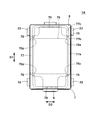
- FIG. 8 is a plan view of the breaker 1 viewed from the thickness direction of the cover piece 9.
- the case body 7 has a region 78 where the projecting portion 77 and the cover piece 9 overlap in plan view. That is, the projecting portion 77 and the cover piece 9 overlap at least partially in plan view as viewed from the thickness direction of the cover piece 9. Accordingly, when the case body 7 and the cover member 8 are fixed, the bending of the cover member 8 in the region 78 is reduced, and a decrease in the pressure acting on the top of the protrusion 77 is suppressed. Better fixation is obtained between the second fixing surface 85 and the second fixing surface 85.
- the case body 7 has a region 78 where the projecting portion 77 and the cover piece 9 overlap near the outside of the four corners 76z of the rectangular region 76 in plan view.
- the case body 7 is formed in a rectangular shape that is long in the longitudinal direction D1 of the movable piece 4 in a plan view.
- the projecting portion 77 has a first portion 77a extending linearly in parallel with the long side of the case body 7 along the opening 73c, and a movable piece in a region 78 which is continuous from the first portion 77a and is close to four corners 76z. 4 and a second portion 77b that is bent inward in the short direction D2.
- the case body 7 and the lid member 8 are more firmly fixed around the opening 73c by the second portion 77b bent inward from the first portion 77a.
- the second portion 77b at least partially overlaps the cover piece 9 in plan view.
- the protruding portion 77 further includes a third portion 77c extending linearly in parallel with the first portion 77a, continuing from the second portion 77b.
- the third portion 77c is provided more inward in the short direction D2 than the first portion 77a.
- the first portion 77a, the second portion 77b, and the third portion 77c form a projecting portion 77 meandering in a zigzag manner in a region 78 near the four corners 76z.
- the protruding portions 77 are densely arranged in the region 78 near the four corners 76z, and the case body 7 and the lid member 8 are further firmly fixed.
- the third portion 77c at least partially overlaps the cover piece 9 in plan view.
- the third portion 77c arranged near the terminal 22, in the region on the side of the second portion 77b it overlaps with the cover piece 9 in plan view.
- the case body 7 has a region 79 where the projecting portion 77 and the cover piece 9 overlap near both ends in the longitudinal direction D1 of the case body 7 in plan view. Accordingly, the case body 7 and the lid member 8 are further firmly fixed together with the overlapping of the projecting portion 77 and the cover piece 9 in the above-described region 78.
- the breaker 1A of the second invention is not limited to the configuration of the above-described embodiment, but may be implemented in various forms. That is, the breaker 1 ⁇ / b> A has at least the fixed contact 21, the elastic portion 43 formed in a plate shape and elastically deformed, and the movable contact 41 at one end of the elastic portion 43, and presses the movable contact 41 against the fixed contact 21.
- the movable piece 4 to be brought into contact with the movable piece 4 is deformed in accordance with a change in temperature, thereby changing the state of the movable piece 4 from a conduction state in which the movable contact 41 contacts the fixed contact 21 to a cut-off state in which the movable contact 41 is separated from the fixed contact 21.
- a heat responsive element 5 to be moved a case body 7 having an opening 73c for accommodating the movable piece 4 and the heat responsive element 5, a lid member 8 attached to the case body 7 to close the opening 73c, and a lid member 8.
- a breaker 1 having a plate-shaped cover piece 9 embedded in a case body 8.
- the case body 7 has a first fixing surface 75 fixed to the lid member 8 formed continuously around the opening 73c.
- Lid 8 a second fixing surface 85 fixed to the case body 7 is formed continuously facing the first fixing surface 75, and the first fixing surface 75 protrudes toward the second fixing surface 85.
- the projecting portion 77 may be formed, and the projecting portion 77 and the cover piece 9 may be at least partially overlapped in a plan view as viewed from the thickness direction of the cover piece 9.
- the outer edge of the case main body 7 may be formed along the protrusion 77. More specifically, the side wall 74 of the case main body 7 may be formed to be depressed inward in the short direction D2 along the second portion 77b and the third portion 77c near the terminals 22 and 32. Good. Similarly, the outer edge of the lid member 8 may be formed along the protrusion 77. With such a configuration, it is possible to suppress the width dimension of the breaker 1A in the short direction D2 while securing the amount of protrusion of the terminals 22 and 32 from the side wall 74.
- the first invention and the second invention may be applied to a form in which the second terminal piece 3 and the movable piece 4 are integrally formed as shown in, for example, WO2011 / 105175. Further, the first invention and the second invention may be applied to a form in which the terminal 22 and the like protrude in the longitudinal direction of the case as shown in the publication.
- the breakers 1 and 1A of the first and second aspects of the present invention have a self-holding circuit using the PTC thermistor 6, but can be applied to a form in which such a configuration is omitted.
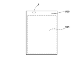
- FIG. 9 shows a secondary battery pack 500.
- the secondary battery pack 500 includes a secondary battery 501, a breaker 1 provided in an output terminal circuit of the secondary battery 501, and the like.
- FIG. 10 shows a safety circuit 502 for an electric device.
- the safety circuit 502 includes a breaker 1 in series in the output circuit of the secondary battery 501.
- a part of the safety circuit 502 may be constituted by a cable including a connector provided with a breaker.
Landscapes
- Chemical & Material Sciences (AREA)
- Chemical Kinetics & Catalysis (AREA)
- Electrochemistry (AREA)
- General Chemical & Material Sciences (AREA)
- Engineering & Computer Science (AREA)
- Physics & Mathematics (AREA)
- Thermal Sciences (AREA)
- Microelectronics & Electronic Packaging (AREA)
- Manufacturing & Machinery (AREA)
- Thermally Actuated Switches (AREA)
Abstract
L'invention concerne un disjoncteur 1 comportant : un contact fixe 21; une pièce mobile 4 ayant une partie élastique 43 et un contact mobile 41; un élément thermosensible 5 qui se déforme lorsqu'il est soumis à un changement de température de façon à amener l'état de la pièce mobile 4 à passer d'un état conducteur à un état déconnecté; un corps de boîtier 7 logeant la pièce mobile 4 et l'élément thermosensible 5; un élément couvercle 8 fixé au corps de boîtier 7; et une pièce de recouvrement en forme de plaque 9 incorporée dans l'élément couvercle 8. Une première surface de fixation 75 à fixer à l'élément couvercle 8 est formée sur le corps de boîtier 7, et une seconde surface de fixation 85 à fixer au corps de boîtier 7 est formée sur l'élément couvercle 8. Une partie saillante 86 faisant saillie vers la première surface de fixation 75 est formée sur la seconde surface de fixation 85, et dans une vue en plan telle que vue depuis le sens de l'épaisseur de la pièce de recouvrement 9, la partie de projection 86 et la pièce de recouvrement 9 se chevauchent l'une l'autre.
Priority Applications (2)
| Application Number | Priority Date | Filing Date | Title |
|---|---|---|---|
| CN201980051872.1A CN112534537B (zh) | 2018-08-27 | 2019-08-19 | 断路器、安全电路以及二次电池组 |
| US17/269,979 US11551895B2 (en) | 2018-08-27 | 2019-08-19 | Breaker, safety circuit and secondary battery pack |
Applications Claiming Priority (2)
| Application Number | Priority Date | Filing Date | Title |
|---|---|---|---|
| JP2018-158064 | 2018-08-27 | ||
| JP2018158064A JP6997689B2 (ja) | 2018-08-27 | 2018-08-27 | ブレーカー、安全回路及び2次電池パック |
Publications (1)
| Publication Number | Publication Date |
|---|---|
| WO2020045144A1 true WO2020045144A1 (fr) | 2020-03-05 |
Family
ID=69643901
Family Applications (1)
| Application Number | Title | Priority Date | Filing Date |
|---|---|---|---|
| PCT/JP2019/032269 WO2020045144A1 (fr) | 2018-08-27 | 2019-08-19 | Disjoncteur, circuit de sécurité et bloc-batterie secondaire |
Country Status (4)
| Country | Link |
|---|---|
| US (1) | US11551895B2 (fr) |
| JP (1) | JP6997689B2 (fr) |
| CN (1) | CN112534537B (fr) |
| WO (1) | WO2020045144A1 (fr) |
Families Citing this family (2)
| Publication number | Priority date | Publication date | Assignee | Title |
|---|---|---|---|---|
| US11848454B2 (en) * | 2020-04-09 | 2023-12-19 | Apple Inc. | Battery enclosures with structural enhancements |
| JP7492495B2 (ja) | 2021-10-06 | 2024-05-29 | ボーンズ株式会社 | ブレーカー、安全回路及び2次電池パック |
Citations (5)
| Publication number | Priority date | Publication date | Assignee | Title |
|---|---|---|---|---|
| JP2006100054A (ja) * | 2004-09-29 | 2006-04-13 | Texas Instr Japan Ltd | 耐圧力性を有するバッテリープロテクタ |
| WO2011105175A1 (fr) * | 2010-02-26 | 2011-09-01 | 株式会社小松ライト製作所 | Rupteur |
| JP2013222533A (ja) * | 2012-04-13 | 2013-10-28 | Komatsulite Mfg Co Ltd | ブレーカー及びそれを備えた安全回路並びに2次電池 |
| JP2015162448A (ja) * | 2014-02-28 | 2015-09-07 | 株式会社小松ライト製作所 | ブレーカー及びそれを備えた安全回路並びに2次電池回路 |
| JP2016039122A (ja) * | 2014-08-11 | 2016-03-22 | 株式会社小松ライト製作所 | スイッチ及びスイッチの製造方法 |
Family Cites Families (18)
| Publication number | Priority date | Publication date | Assignee | Title |
|---|---|---|---|---|
| ATE44630T1 (de) * | 1984-05-30 | 1989-07-15 | Lectra Trading Ag | Ueberlastsicherungsschalter. |
| CA2208910C (fr) * | 1996-07-04 | 2001-11-06 | Ubukata Industries Co., Ltd. | Systeme de protection thermique pour moteurs electriques |
| JP3744259B2 (ja) * | 1999-05-25 | 2006-02-08 | 松下電工株式会社 | 回路遮断器 |
| US6633222B2 (en) * | 2000-08-08 | 2003-10-14 | Furukawa Precision Engineering Co., Ltd. | Battery breaker |
| ITMI20012586A1 (it) * | 2001-12-10 | 2003-06-10 | Abb Service Srl | Polo elettrico per un interruttore di potenza di bassa tensione, e relativo interruttore |
| JP4087603B2 (ja) * | 2001-12-25 | 2008-05-21 | アルプス電気株式会社 | スライド型電気部品 |
| JP2004220944A (ja) * | 2003-01-15 | 2004-08-05 | Furukawa Electric Co Ltd:The | サーマルプロテクタ |
| JP2007329031A (ja) * | 2006-06-08 | 2007-12-20 | Mitsubishi Electric Corp | 回路遮断器 |
| CN104025235B (zh) * | 2011-10-14 | 2016-08-24 | 小松电子部品有限公司 | 断路器、具备该断路器的安全电路以及二次电池 |
| CN102568958B (zh) * | 2011-12-31 | 2016-09-28 | 上海长园维安电子线路保护有限公司 | 自保持型过电流保护装置 |
| JP6085116B2 (ja) * | 2012-08-10 | 2017-02-22 | ボーンズ株式会社 | ブレーカー及びそれを備えた安全回路並びに2次電池 |
| JP6224920B2 (ja) * | 2013-06-03 | 2017-11-01 | ボーンズ株式会社 | ブレーカー及びそれを備えた安全回路並びに2次電池回路 |
| JP6408822B2 (ja) * | 2014-07-30 | 2018-10-17 | ボーンズ株式会社 | ブレーカー及びそれを備えた安全回路並びに2次電池回路 |
| JP2016035822A (ja) * | 2014-08-01 | 2016-03-17 | 株式会社小松ライト製作所 | 電気部品及びそれを備えた回路基板並びに2次電池回路。 |
| JP6393119B2 (ja) | 2014-08-29 | 2018-09-19 | ボーンズ株式会社 | ブレーカー及びそれを備えた安全回路並びに2次電池回路。 |
| CN204516706U (zh) * | 2015-04-24 | 2015-07-29 | 浙江奔一电气有限公司 | 一种小型多断点断路器 |
| WO2017086486A1 (fr) * | 2015-11-20 | 2017-05-26 | ボーンズ株式会社 | Boîtier de dispositif électronique, procédé de fabrication de boîtier de dispositif électronique, et disjoncteur pourvu d'un boîtier de dispositif électronique |
| CN108231478A (zh) * | 2017-12-29 | 2018-06-29 | 中国电子科技集团公司第四十研究所 | 一种耐环境密封超小型恒温继电器 |
-
2018
- 2018-08-27 JP JP2018158064A patent/JP6997689B2/ja active Active
-
2019
- 2019-08-19 CN CN201980051872.1A patent/CN112534537B/zh active Active
- 2019-08-19 US US17/269,979 patent/US11551895B2/en active Active
- 2019-08-19 WO PCT/JP2019/032269 patent/WO2020045144A1/fr active Application Filing
Patent Citations (5)
| Publication number | Priority date | Publication date | Assignee | Title |
|---|---|---|---|---|
| JP2006100054A (ja) * | 2004-09-29 | 2006-04-13 | Texas Instr Japan Ltd | 耐圧力性を有するバッテリープロテクタ |
| WO2011105175A1 (fr) * | 2010-02-26 | 2011-09-01 | 株式会社小松ライト製作所 | Rupteur |
| JP2013222533A (ja) * | 2012-04-13 | 2013-10-28 | Komatsulite Mfg Co Ltd | ブレーカー及びそれを備えた安全回路並びに2次電池 |
| JP2015162448A (ja) * | 2014-02-28 | 2015-09-07 | 株式会社小松ライト製作所 | ブレーカー及びそれを備えた安全回路並びに2次電池回路 |
| JP2016039122A (ja) * | 2014-08-11 | 2016-03-22 | 株式会社小松ライト製作所 | スイッチ及びスイッチの製造方法 |
Also Published As
| Publication number | Publication date |
|---|---|
| CN112534537A (zh) | 2021-03-19 |
| JP2020035515A (ja) | 2020-03-05 |
| CN112534537B (zh) | 2024-04-23 |
| US11551895B2 (en) | 2023-01-10 |
| US20210313129A1 (en) | 2021-10-07 |
| JP6997689B2 (ja) | 2022-01-18 |
Similar Documents
| Publication | Publication Date | Title |
|---|---|---|
| CN110651349B (zh) | 断路器及具备该断路器的安全电路 | |
| US11239037B2 (en) | Breaker and safety circuit equipped with the same | |
| WO2020045144A1 (fr) | Disjoncteur, circuit de sécurité et bloc-batterie secondaire | |
| WO2019124338A1 (fr) | Disjoncteur et circuit de sécurité le comprenant | |
| US11329325B2 (en) | Breaker and safety circuit provided with same | |
| JP6967932B2 (ja) | ブレーカー及びそれを備えた安全回路。 | |
| JP7083742B2 (ja) | 熱応動素子、ブレーカー、安全回路及び2次電池パック | |
| WO2020031849A1 (fr) | Disjoncteur et circuit de sécurité | |
| WO2020027052A1 (fr) | Interrupteur de courant, circuit de sécurité et bloc-batterie secondaire | |
| WO2020022298A1 (fr) | Disjoncteur, circuit de sécurité et bloc de batterie secondaire | |
| JP7425710B2 (ja) | ブレーカー及びそれを備えた安全回路、2次電池パック | |
| WO2023119887A1 (fr) | Disjoncteur, circuit de sécurité et bloc-batterie secondaire | |
| WO2020095694A1 (fr) | Élément actionné thermiquement, disjoncteur, circuit de sécurité et bloc-batterie secondaire | |
| WO2020084739A1 (fr) | Circuit d'accumulateur et son procédé de production | |
| JP2023072318A (ja) | ブレーカー、安全回路及び2次電池パック | |
| JP2023055473A (ja) | ブレーカー、安全回路及び2次電池パック | |
| JP2023095410A (ja) | ブレーカー、安全回路及び2次電池パック | |
| JP2018010837A (ja) | ブレーカー及びそれを備えた安全回路並びに2次電池回路。 |
Legal Events
| Date | Code | Title | Description |
|---|---|---|---|
| 121 | Ep: the epo has been informed by wipo that ep was designated in this application |
Ref document number: 19855608 Country of ref document: EP Kind code of ref document: A1 |
|
| NENP | Non-entry into the national phase |
Ref country code: DE |
|
| 122 | Ep: pct application non-entry in european phase |
Ref document number: 19855608 Country of ref document: EP Kind code of ref document: A1 |