WO2020039940A1 - ガラス板の製造方法および砥石装置用工具 - Google Patents
ガラス板の製造方法および砥石装置用工具 Download PDFInfo
- Publication number
- WO2020039940A1 WO2020039940A1 PCT/JP2019/031212 JP2019031212W WO2020039940A1 WO 2020039940 A1 WO2020039940 A1 WO 2020039940A1 JP 2019031212 W JP2019031212 W JP 2019031212W WO 2020039940 A1 WO2020039940 A1 WO 2020039940A1
- Authority
- WO
- WIPO (PCT)
- Prior art keywords
- grindstone
- spindle
- tool
- grinding wheel
- holder
- Prior art date
- Legal status (The legal status is an assumption and is not a legal conclusion. Google has not performed a legal analysis and makes no representation as to the accuracy of the status listed.)
- Ceased
Links
Images



Classifications
-
- B—PERFORMING OPERATIONS; TRANSPORTING
- B24—GRINDING; POLISHING
- B24B—MACHINES, DEVICES, OR PROCESSES FOR GRINDING OR POLISHING; DRESSING OR CONDITIONING OF ABRADING SURFACES; FEEDING OF GRINDING, POLISHING, OR LAPPING AGENTS
- B24B45/00—Means for securing grinding wheels on rotary arbors
-
- B—PERFORMING OPERATIONS; TRANSPORTING
- B24—GRINDING; POLISHING
- B24B—MACHINES, DEVICES, OR PROCESSES FOR GRINDING OR POLISHING; DRESSING OR CONDITIONING OF ABRADING SURFACES; FEEDING OF GRINDING, POLISHING, OR LAPPING AGENTS
- B24B7/00—Machines or devices designed for grinding plane surfaces on work, including polishing plane glass surfaces; Accessories therefor
- B24B7/20—Machines or devices designed for grinding plane surfaces on work, including polishing plane glass surfaces; Accessories therefor characterised by a special design with respect to properties of the material of non-metallic articles to be ground
- B24B7/22—Machines or devices designed for grinding plane surfaces on work, including polishing plane glass surfaces; Accessories therefor characterised by a special design with respect to properties of the material of non-metallic articles to be ground for grinding inorganic material, e.g. stone, ceramics, porcelain
- B24B7/24—Machines or devices designed for grinding plane surfaces on work, including polishing plane glass surfaces; Accessories therefor characterised by a special design with respect to properties of the material of non-metallic articles to be ground for grinding inorganic material, e.g. stone, ceramics, porcelain for grinding or polishing glass
- B24B7/242—Machines or devices designed for grinding plane surfaces on work, including polishing plane glass surfaces; Accessories therefor characterised by a special design with respect to properties of the material of non-metallic articles to be ground for grinding inorganic material, e.g. stone, ceramics, porcelain for grinding or polishing glass for plate glass
-
- B—PERFORMING OPERATIONS; TRANSPORTING
- B24—GRINDING; POLISHING
- B24B—MACHINES, DEVICES, OR PROCESSES FOR GRINDING OR POLISHING; DRESSING OR CONDITIONING OF ABRADING SURFACES; FEEDING OF GRINDING, POLISHING, OR LAPPING AGENTS
- B24B9/00—Machines or devices designed for grinding edges or bevels on work or for removing burrs; Accessories therefor
- B24B9/02—Machines or devices designed for grinding edges or bevels on work or for removing burrs; Accessories therefor characterised by a special design with respect to properties of materials specific to articles to be ground
- B24B9/06—Machines or devices designed for grinding edges or bevels on work or for removing burrs; Accessories therefor characterised by a special design with respect to properties of materials specific to articles to be ground of non-metallic inorganic material, e.g. stone, ceramics, porcelain
- B24B9/08—Machines or devices designed for grinding edges or bevels on work or for removing burrs; Accessories therefor characterised by a special design with respect to properties of materials specific to articles to be ground of non-metallic inorganic material, e.g. stone, ceramics, porcelain of glass
- B24B9/10—Machines or devices designed for grinding edges or bevels on work or for removing burrs; Accessories therefor characterised by a special design with respect to properties of materials specific to articles to be ground of non-metallic inorganic material, e.g. stone, ceramics, porcelain of glass of plate glass
-
- B—PERFORMING OPERATIONS; TRANSPORTING
- B24—GRINDING; POLISHING
- B24D—TOOLS FOR GRINDING, BUFFING OR SHARPENING
- B24D5/00—Bonded abrasive wheels, or wheels with inserted abrasive blocks, designed for acting only by their periphery; Bushings or mountings therefor
- B24D5/16—Bushings; Mountings
Definitions
- the present invention provides a method of manufacturing a glass plate including a step of removing a grindstone holder (for example, a grindstone flange) and a grindstone from a spindle provided in a rotary grindstone device, and cancels the engagement between the spindle and the grindstone holder for removal.
- a grindstone holder for example, a grindstone flange
- the present invention provides a method of manufacturing a glass plate including a step of removing a grindstone holder (for example, a grindstone flange) and a grindstone from a spindle provided in a rotary grindstone device, and cancels the engagement between the spindle and the grindstone holder for removal.
- a grindstone holder for example, a grindstone flange
- the manufacturing process of a glass sheet often includes an end face processing step in which an end face of the glass sheet is ground or polished with a grindstone. It is customary to use a rotary grindstone device provided with a grindstone to execute the end face processing step.
- the end surface of the wafer is processed instead of the end surface of the glass plate, and an example of a rotary grindstone device is disclosed in Patent Document 1.
- the apparatus disclosed in the document includes a spindle (motor rotating shaft 40) having a tapered tip end, and a grinding wheel flange (flange body) having a tapered hole (hole 18) fitted with the spindle. 12), a fixing tool (hex cap bolt 34) for fixing the spindle and the grindstone flange in a fitted state, and a state in which the periphery of the spindle is mounted on the outer peripheral surface of the shaft portion (shaft portion 17) of the grindstone flange. And a rotating annular grindstone (grindstone 50).
- Patent Literature 1 when the grinding wheel flange and the grinding wheel are exchanged, first, the grinding wheel is removed from the shaft portion of the grinding wheel flange, and in this state, the fixing between the spindle and the grinding wheel flange by the fixture is released. Next, the fitting between the spindle, which has been released, and the grinding wheel flange is released.
- a tool for a grindstone device is used to release the fitting. An example of this tool for a grindstone device is disclosed in Patent Document 1.
- a female screw is formed which meshes with a male screw formed on the outer peripheral surface of the shaft portion of the grinding wheel flange, and is fixed to the outer peripheral surface of the shaft portion using the engagement of both screws.
- a possible first member (disk 44) and a male screw meshing with a female screw formed on the inner peripheral surface of the through hole of the first member are formed, and the axial direction of the spindle is adjusted by using the meshing of the two screws.
- a second member (pulling bolt 46) which can be fed and moved.
- the first member When releasing the engagement between the spindle and the grindstone flange using the above-described tool, the first member is fixed to the outer peripheral surface of the shaft portion of the grindstone flange, and the second member is inserted into the through hole of the first member. Is inserted while rotating, so that the tip of the spindle and the second member abut. In this state, the second member is further rotated to feed and move the second member toward the spindle with respect to the first member. Accordingly, the grindstone flange moves away from the spindle together with the first member, so that the tip of the spindle is pushed out from the hole of the grindstone flange, and the fitting between the spindle and the grindstone flange is released.
- an object of the present invention is to increase the efficiency of work when removing a grindstone holder and a grindstone from a spindle provided in a rotary grindstone device.
- the present invention created to solve the above-mentioned problem, the spindle, a grinding wheel holding tool having a hollow portion in addition to the hole fitting with the spindle, a state in which the spindle and the grinding wheel holding tool is fitted
- a method for manufacturing a glass plate comprising a step of removing a grindstone holder and a grindstone from a spindle with respect to a rotary grindstone device including a fixture to be fixed and an annular grindstone rotating around a spindle mounted on the grindstone holder.
- a fixing releasing step of releasing the fixing between the spindle and the grindstone holder by the fixing tool, and fitting the spindle and the grindstone holding tool in the released state by the tool for the grindstone device.
- a step of releasing the fitting The tool for the grindstone device can be fixed to the hollow portion.
- the tool for the grinding wheel device can be fixed to the hollow portion of the grinding wheel holder, the risk of the tool for the grinding wheel device interfering with the grinding wheel can be reliably eliminated in performing the fitting release step. Therefore, it is possible to naturally eliminate the necessity of removing the grindstone from the grindstone holder when performing the fitting release step. As a result, the work (removing step) for removing the grindstone holder and the grindstone from the spindle can be made more efficient.
- the hollow portion is formed so as to be continuous with the hole portion and along the hole axis direction of the hole portion
- the grindstone device tool includes a first member that can be fixed to the hollow portion, and a spindle with respect to the first member.
- a relative movement of the second member with respect to the first member, the relative movement of the second member with respect to the first member is performed by a feed movement, in the fitting release step, the grinding wheel holder and the first member In a state where the tip of the spindle and the second member are in contact with each other in the fixed state, the fitting between the spindle and the grindstone holder is released with the relative movement of the first member and the second member.
- the tip of the spindle is detached from the hole of the grindstone holder with the feeding movement under the state where the tip of the spindle and the second member are in contact with each other. Therefore, it is possible to eliminate the need to apply an impact to any of the grindstone device tools (the first member and the second member), the grindstone holder, and the grindstone in performing the fitting release step. As a result, it is possible to prevent the occurrence of a shift between the grindstone holder and the grindstone during the execution of the fitting release step.
- the whetstone holder and the second holding member are engaged with each other using the engagement between the female screw formed on the inner peripheral surface of the hollow portion and the male screw formed on the outer peripheral surface of the first member. It is preferable that one member is fixed.
- a hole is formed in the first member, and the second member has a round bar-shaped portion extending in the axial direction of the spindle. It is preferable that the second member is fed and moved with respect to the first member by utilizing the engagement between the female screw formed on the surface and the male screw formed on the outer peripheral surface of the rod portion of the second member.
- the second member has a handle portion connected to the rod portion and extending in a radial direction of the rod portion.
- the presence of the handle makes it easier to apply torque for rotation to the rod-shaped portion of the second member. Therefore, it is possible to easily rotate the rod portion and feed the second member in the axial direction of the spindle.
- the tool for the grindstone device a first rod member that can be fixed to the hollow portion, a weight that can slide along the longitudinal direction of the first rod member, and a regulating member that regulates the range of sliding of the weight.
- the fitting between the spindle and the grindstone holder may be released with the collision between the weight and the regulating member.
- the regulating member is a second rod member connected to the first rod member and extending in a radial direction of the first rod member.
- the structure of the tool for the grinding wheel device can be simplified, so that the cost for manufacturing the tool for the grinding wheel device can be reduced.
- the second rod member is connected to the end of the first rod member and that the first rod member and the second rod member form a T shape.
- the tool for the grinding wheel device is made of stainless steel.
- the present invention was devised to solve the above-described problems, and a spindle, a grindstone holder having a hollow part in addition to a hole part fitted with the spindle, and a spindle and a grindstone holder are fitted.
- a rotating grindstone device equipped with a fixture that fixes in a state and an annular grindstone that rotates around the spindle while being mounted on the grindstone holder, when the grindstone holder and the grindstone are removed from the spindle, fixing with the fixture is performed.
- the hollow portion is continuous with the hole portion and is formed along the hole axis direction of the hole portion, and the first member which can be fixed to the hollow portion, the axial direction of the spindle with respect to the first member. And a second member which can be fed and moved and can contact the tip of the spindle.
- the efficiency of the work can be improved when the grindstone holder and the grindstone are removed from the spindle provided in the rotary grindstone device.
- the method for manufacturing a glass plate according to the present embodiment includes a step of removing a grindstone holder and a grindstone from a spindle provided in a rotary grindstone device, as described later. First, the configuration of the rotary grindstone device will be described.
- the rotary grindstone device 1 fits a spindle 2, a grindstone flange 3 (grindstone holding tool) having a hole 3 a fitted with the spindle 2, and the spindle 2 and the grindstone flange 3. It includes a bolt 4 and a holding plate 5 as a fixture for fixing in a state where the grinding wheel is fixed, and an annular grindstone 6 that rotates around the spindle 2 while being attached to the grindstone flange 3.
- the spindle 2 has a tip 2a formed in a tapered shape.
- the distal end portion 2a is formed such that the outer diameter decreases as it moves from the lower side to the upper side (from the base end side to the distal end side).
- a female screw (not shown) that meshes with a male screw (not shown) formed on the bolt 4 is formed inside the distal end portion 2a.
- the spindle 2 rotates together with the grindstone flange 3 and the grindstone 6 with power transmission from a drive device (not shown) such as a motor.
- the grinding wheel flange 3 has a flange portion 3b that supports the grinding wheel 6 from below, and a shaft portion 3c that continues above the flange portion 3b.
- the hole 3a formed in the flange 3b is formed in a tapered shape that fits with the tip 2a of the spindle 2, and is formed such that the inner diameter decreases as it moves upward from the lower side.
- the upper end of the hole 3a and the tip of the spindle 2 are flush with each other, but the upper end position of the hole 3a (the bottom surface position of a hollow portion 3d described later) is higher than the tip position of the spindle 2. May be higher.
- the hole axis of the hole 3 a coincides with the axis of the spindle 2.
- the hollow portion 3d connected to the hole 3a is formed in the shaft portion 3c.
- the shaft portion 3c is formed in a cylindrical shape.
- the hollow part 3d is formed along the hole axis direction of the hole part 3a, and is formed so that the opening shape is circular.
- the inner diameter of the circle formed by the opening is larger than the inner diameter at the upper end (upper end of the taper) of the hole 3a.
- the hole axis of the hollow part 3d coincides with the axis of the spindle 2 in the same manner as the hole axis of the hole part 3a.
- a female screw 3e is formed on the inner peripheral surface of the hollow portion 3d.
- the bolt 4 penetrates a hole (not shown) formed in the holding plate 5 and is fastened to the distal end 2 a of the spindle 2 with its head pressing the holding plate 5 against the spindle 2. .
- the spindle 2 and the grinding wheel flange 3 are fixed.
- the grindstone 6 is mounted on the grindstone flange 3 such that the center of the ring (ring) formed by the grindstone 6 coincides with the axis of the spindle 2.
- the attachment of the grindstone 6 to the grindstone flange 3 is performed by bolts (not shown).
- grooves (not shown) for processing the end surface of the glass plate are formed over a plurality of upper and lower stages.
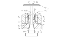
- the removing step includes a fixing releasing step (FIG. 2) for releasing the fixing of the spindle 2 and the grinding wheel flange 3 by the bolt 4 and the holding plate 5, and the fitting of the spindle 2 and the grinding stone flange 3 in the released state. Is released by the grindstone device tool 7 (FIG. 3).
- the tool 7 for a grindstone device has a first member 8 formed in a bolt shape and a second member 9 formed in a T shape.
- the material of the tool 7 for a grinding wheel device is not particularly limited, but in this embodiment, stainless steel is used as the material.
- the first member 8 has a main body 8a and a head 8b connected to one end of the main body 8a.
- the first member 8 has a hole 8c passing therethrough, and a female screw 8d is formed on the inner peripheral surface of the hole 8c.
- a male screw 8e is formed on the outer peripheral surface of the main body portion 8a, and the male screw 8e meshes with a female screw 3e formed on the inner peripheral surface of the hollow portion 3d of the grindstone flange 3.
- the outer diameter of the head 8b is slightly larger than the main body 8a, and the outer diameter of the head 8b is larger than the inner diameter of the circle formed by the opening of the hollow portion 3d of the grindstone flange 3.
- the outer diameter of the head 8b is smaller than the inner diameter of the ring (ring) formed by the grindstone 6.
- the second member 9 has a round bar-shaped bar portion 9a and a handle portion 9b connected to the bar portion 9a and extending in the radial direction of the bar portion 9a.
- the outer diameter of the rod portion 9a is smaller than the inner diameter at the upper end of the hole 3a of the grinding wheel flange 3.
- a male screw 9c is formed on the outer peripheral surface of the rod portion 9a, and the male screw 9c meshes with a female screw 8d formed on the inner peripheral surface of the hole 8c of the first member 8.
- the female screw 8d formed on the inner peripheral surface of the hole 8c of the first member 8 and the male screw 9c formed on the outer peripheral surface of the rod portion 9a of the second member 9 are engaged with each other.
- the first member 8 is placed in the hollow portion 3 d of the grindstone flange 3 while the grindstone 6 is mounted on the grindstone flange 3. Fix it. Specifically, the female screw 3e formed on the inner peripheral surface of the hollow portion 3d of the grindstone flange 3 and the male screw 8e formed on the outer peripheral surface of the main body 8a of the first member 8 are relatively rotated while being engaged. By doing so, the first member 8 is attached to the grindstone flange 3, and the head 8 b of the first member 8 is brought into contact with the shaft 3 c of the grindstone flange 3.
- a female screw 8d formed on the inner peripheral surface of the hole 8c of the first member 8 and a male screw 9c formed on the outer peripheral surface of the rod portion 9a of the second member 9 are formed. Bite. At this time, the rod portion 9a of the second member 9 extends in the axial direction of the spindle 2. Then, while engaging the two screws 8d and 9c, the handle 9b of the second member 9 is operated to rotate the rod 9a. Along with this, the rod-shaped portion 9a is sent toward the spindle 2 (lower side) and moves with respect to the first member 8.
- the bar-shaped portion 9a When the bar-shaped portion 9a is sent toward the spindle 2 as described above, the bar-shaped portion 9a comes into contact with the tip of the spindle 2 as shown in FIG. 6, and the bar-shaped portion 9a cannot move further downward. Become. In this state, the handle 9b of the second member 9 is further operated to rotate the bar 9a, so that the bar 9a is moved toward the spindle 2 with respect to the first member 8. In this case, since the rod portion 9a cannot move downward, the first member 8 moves upward (upward) away from the spindle 2 as shown in FIG. At this time, the grinding wheel flange 3 fixed to the first member 8 also moves upward. Along with this, the hole 3a of the grinding wheel flange 3 rises from the tip 2a of the spindle 2, and the engagement between the spindle 2 and the grinding wheel flange 3 is released.
- the fitting releasing step is completed, and all the steps included in the removing step are completed.
- the grinding wheel flange 3 and the grinding wheel 6 are removed from the spindle 2 provided in the rotary grinding wheel device 1.
- the first member 8 (the tool 7 for the grinding wheel device) is fixed to the hollow portion 3d of the grinding wheel flange 3 at the time of executing the fitting release step, so that the risk of interference with the grinding wheel 6 can be reliably eliminated. Therefore, it is possible to eliminate the necessity of removing the grindstone 6 from the grindstone flange 3 when executing the fitting release step. As a result, the efficiency of the operation for removing the grinding wheel flange 3 and the grinding wheel 6 from the spindle 2 can be improved.
- the second embodiment is different from the first embodiment in that the configuration of the grindstone device tool 7 used in the fitting releasing step and the fitting releasing step It is an aspect of execution.
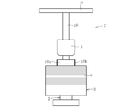
- the grindstone device tool 7 includes a vertical rod 10 as a first rod member that can be fixed to a hollow portion 3 d (not shown) of the grindstone flange 3, and a weight that can slide up and down along the longitudinal direction of the vertical rod 10. 11 and a horizontal bar 12 as a regulating member (second rod member) for regulating the range of sliding of the weight 11.
- the upper end of the vertical bar 10 is connected to the center of the horizontal bar 12, forming a T-shape by the two 10, 12.
- the horizontal bar 12 extends in the radial direction of the vertical bar 10.
- the vertical bar 10 and the horizontal bar 12 may intersect with each other so as to form a cross shape by the two 10 and 12.
- a male screw 10b is formed on the outer peripheral surface of the lower end portion 10a of the vertical bar 10, and the hollow portion 3d of the grindstone flange 3 Can be meshed with a female screw 3e (not shown) formed on the inner peripheral surface of the internal thread. Thereby, the hollow portion 3d of the grinding wheel flange 3 and the vertical bar 10 are fixed.
- the weight 11 has a through-hole (not shown) formed therein, and an intermediate portion between the lower end 10a and the upper end of the vertical rod 10 is inserted into the through-hole. Therefore, the weight 11 can slide up and down along the longitudinal direction of the vertical bar 10.
- the inner diameter of the through hole of the weight 11 is larger than the outer diameter of the middle part of the vertical rod 10 and smaller than the outer diameter of the lower end 10 a of the vertical rod 10. For this reason, the range in which the weight 11 can slide is restricted between the lower end portion 10a and the upper end portion (horizontal bar 12) of the vertical bar 10.
- the method for manufacturing a glass plate and the tool for a grindstone device according to the present invention are not limited to the aspects and configurations described in the above embodiment.
- the screw mechanism is used to fix the first member or the vertical rod to the grinding wheel flange, but the present invention is not limited to this.
- the first member or the vertical rod may be fixed to the grindstone flange by using a chuck mechanism having a claw or the like instead of the screw mechanism.
- the screw mechanism is used to feed and move the second member with respect to the first member.
- the first member and the second member may be fed and moved by using a rack-and-pinion mechanism instead of the screw mechanism.
- a pinion may be provided on the first member and a rack may be provided on the second member, and the second member may be moved with respect to the first member as the pinion rotates.
- the grinding wheel flange is used as the grinding wheel holder on which the grinding wheel is mounted, but the invention is not limited to this. As long as it has a hollow portion in addition to the hole to be fitted with the spindle, a grindstone holder of another shape may be used instead of the grindstone flange. Further, in the above-described second embodiment, the hollow portion only needs to be able to fix the first rod member (vertical rod 10), and need not be connected to the hole.
Landscapes
- Engineering & Computer Science (AREA)
- Mechanical Engineering (AREA)
- Chemical & Material Sciences (AREA)
- Ceramic Engineering (AREA)
- Inorganic Chemistry (AREA)
- Polishing Bodies And Polishing Tools (AREA)
- Grinding And Polishing Of Tertiary Curved Surfaces And Surfaces With Complex Shapes (AREA)
- Surface Treatment Of Glass (AREA)
- Constituent Portions Of Griding Lathes, Driving, Sensing And Control (AREA)
Abstract
Description
本実施形態に係るガラス板の製造方法は、後述のように、回転砥石装置に備わったスピンドルから砥石保持具および砥石を取り外す工程を含んでいる。はじめに、回転砥石装置の構成について説明する。
図8及び図9に示すように、第二実施形態が、上記の第一実施形態と相違している点は、嵌合解除工程に用いる砥石装置用工具7の構成、及び、嵌合解除工程の実行の態様である。
2 スピンドル
2a 先端部
3 砥石フランジ(砥石保持具)
3a 孔部
3d 中空部
3e 雌ネジ
4 ボルト
5 押え板
6 砥石
7 砥石装置用工具
8 第一部材
8c 孔
8d 雌ネジ
8e 雄ネジ
9 第二部材
9a 棒状部
9b ハンドル部
9c 雄ネジ
10 鉛直棒
11 錘
12 水平棒
Claims (12)
- スピンドルと、前記スピンドルと嵌合する孔部に加えて中空部を有する砥石保持具と、前記スピンドルと前記砥石保持具とを嵌合させた状態で固定する固定具と、前記砥石保持具に装着された状態で前記スピンドル周りを回転する環状の砥石とを備えた回転砥石装置について、前記スピンドルから前記砥石保持具および前記砥石を取り外す工程を含んだガラス板の製造方法であって、
前記取り外す工程が、前記固定具による前記スピンドルと前記砥石保持具との固定を解除する固定解除工程と、固定が解除された状態にある前記スピンドルと前記砥石保持具との嵌合を砥石装置用工具により解除する嵌合解除工程とを含み、
前記砥石装置用工具が、前記中空部に固定可能であることを特徴とするガラス板の製造方法。 - 前記中空部が、前記孔部と連なり且つ前記孔部の孔軸方向に沿って形成され、
前記砥石装置用工具が、前記中空部に固定可能な第一部材と、前記第一部材に対して前記スピンドルの軸心方向に相対移動可能な第二部材とを有し、
前記第一部材に対する前記第二部材の相対移動は、送り移動によって行われ、
前記嵌合解除工程では、前記砥石保持具と前記第一部材とを固定した状態で且つ前記スピンドルの先端と前記第二部材とを当接させた状態で、前記第一部材と前記第二部材とを相対移動させることに伴って、前記スピンドルと前記砥石保持具との嵌合を解除することを特徴とする請求項1に記載のガラス板の製造方法。 - 前記嵌合解除工程では、前記中空部の内周面に形成された雌ネジと、前記第一部材の外周面に形成された雄ネジとの噛み合いを利用して、前記砥石保持具と前記第一部材とを固定することを特徴とする請求項2に記載のガラス板の製造方法。
- 前記第一部材に孔が形成されると共に、前記第二部材が前記スピンドルの軸心方向に延びる丸棒状の棒状部を有し、
前記嵌合解除工程では、前記第一部材の前記孔の内周面に形成された雌ネジと、前記第二部材の前記棒状部の外周面に形成された雄ネジとの噛み合いを利用して、前記第一部材に対して前記第二部材を送り移動させることを特徴とする請求項2又は3に記載のガラス板の製造方法。 - 前記第二部材が、前記棒状部と連結され且つ前記棒状部の径方向に延びたハンドル部を有することを特徴とする請求項4に記載のガラス板の製造方法。
- 前記砥石装置用工具が、前記中空部に固定可能な第一棒部材と、前記第一棒部材の長手方向に沿ってスライド可能な錘と、前記錘のスライドの範囲を規制する規制部材とを有し、
前記嵌合解除工程では、前記錘と前記規制部材とを衝突させることに伴って、前記スピンドルと前記砥石保持具との嵌合を解除することを特徴とする請求項1に記載のガラス板の製造方法。 - 前記規制部材が、前記第一棒部材に連結され且つ前記第一棒部材の径方向に延びた第二棒部材であることを特徴とする請求項6に記載のガラス板の製造方法。
- 前記第二棒部材が、前記第一棒部材の端部に連結されると共に、前記第一棒部材および前記第二棒部材でT字状をなすことを特徴とする請求項7に記載のガラス板の製造方法。
- 前記砥石装置用工具がステンレス鋼で構成されることを特徴とする請求項1~8のいずれかに記載のガラス板の製造方法。
- スピンドルと、前記スピンドルと嵌合する孔部に加えて中空部を有する砥石保持具と、前記スピンドルと前記砥石保持具とを嵌合させた状態で固定する固定具と、前記砥石保持具に装着された状態で前記スピンドル周りを回転する環状の砥石とを備えた回転砥石装置について、前記スピンドルから前記砥石保持具および前記砥石を取り外すに際し、前記固定具による固定が解除された状態にある前記スピンドルと前記砥石保持具との嵌合を解除するための砥石装置用工具であって、
前記中空部に固定可能であることを特徴とする砥石装置用工具。 - 前記中空部が、前記孔部と連なり且つ前記孔部の孔軸方向に沿って形成され、
前記中空部に固定可能な第一部材と、前記第一部材に対して前記スピンドルの軸心方向に送り移動可能で且つ前記スピンドルの先端と当接可能な第二部材とを有することを特徴とする請求項10に記載の砥石装置用工具。 - 前記中空部に固定可能な第一棒部材と、前記第一棒部材の長手方向に沿ってスライド可能な錘と、前記錘のスライドの範囲を規制する規制部材とを有することを特徴とする請求項10に記載の砥石装置用工具。
Priority Applications (3)
| Application Number | Priority Date | Filing Date | Title |
|---|---|---|---|
| CN201980042804.9A CN112368110A (zh) | 2018-08-22 | 2019-08-07 | 玻璃板的制造方法以及磨石装置用工具 |
| KR1020207032246A KR102725479B1 (ko) | 2018-08-22 | 2019-08-07 | 유리판의 제조 방법 및 숫돌 장치용 공구 |
| JP2020538298A JP7428974B2 (ja) | 2018-08-22 | 2019-08-07 | ガラス板の製造方法および砥石装置用工具 |
Applications Claiming Priority (2)
| Application Number | Priority Date | Filing Date | Title |
|---|---|---|---|
| JP2018-155414 | 2018-08-22 | ||
| JP2018155414 | 2018-08-22 |
Publications (1)
| Publication Number | Publication Date |
|---|---|
| WO2020039940A1 true WO2020039940A1 (ja) | 2020-02-27 |
Family
ID=69593121
Family Applications (1)
| Application Number | Title | Priority Date | Filing Date |
|---|---|---|---|
| PCT/JP2019/031212 Ceased WO2020039940A1 (ja) | 2018-08-22 | 2019-08-07 | ガラス板の製造方法および砥石装置用工具 |
Country Status (5)
| Country | Link |
|---|---|
| JP (1) | JP7428974B2 (ja) |
| KR (1) | KR102725479B1 (ja) |
| CN (1) | CN112368110A (ja) |
| TW (1) | TW202012337A (ja) |
| WO (1) | WO2020039940A1 (ja) |
Cited By (2)
| Publication number | Priority date | Publication date | Assignee | Title |
|---|---|---|---|---|
| WO2023176448A1 (ja) * | 2022-03-15 | 2023-09-21 | 日本電気硝子株式会社 | 工具アセンブリ、加工装置及びガラス板の製造方法 |
| WO2023176451A1 (ja) * | 2022-03-15 | 2023-09-21 | 日本電気硝子株式会社 | 工具アセンブリ、加工装置及びガラス板の製造方法 |
Citations (3)
| Publication number | Priority date | Publication date | Assignee | Title |
|---|---|---|---|---|
| JP2005212066A (ja) * | 2004-01-30 | 2005-08-11 | Tokyo Seimitsu Co Ltd | ウェーハ面取り用砥石の固定フランジ、該フランジの取り外し具及びウェーハ面取り装置の砥石取付方法 |
| JP2014091208A (ja) * | 2012-11-06 | 2014-05-19 | Disco Abrasive Syst Ltd | 工具着脱治具 |
| JP6267043B2 (ja) * | 2014-04-02 | 2018-01-24 | 株式会社ディスコ | ブレード装着工具 |
Family Cites Families (7)
| Publication number | Priority date | Publication date | Assignee | Title |
|---|---|---|---|---|
| CN203542512U (zh) * | 2013-11-15 | 2014-04-16 | 南车株洲电机有限公司 | 一种磨床磨头砂轮拆卸工具 |
| DE102014102329A1 (de) * | 2014-02-24 | 2015-08-27 | Thyssenkrupp Rothe Erde Gmbh | Vorrichtung und Verfahren zur Montage und/oder Demontage eines Klemmringes beim Schleifscheibenwechsel |
| CN204366882U (zh) * | 2014-12-01 | 2015-06-03 | 中国石油天然气股份有限公司 | 拆卸抽油机减速箱曲柄键的工具 |
| JP2016132046A (ja) * | 2015-01-16 | 2016-07-25 | 株式会社ディスコ | マウントフランジ |
| CN204913764U (zh) * | 2015-07-21 | 2015-12-30 | 上海江南轧辊有限公司 | 轧辊磨床砂轮的拆卸安装装置 |
| CN205148067U (zh) * | 2015-11-27 | 2016-04-13 | 贵州大学 | 一种高砂轮线速度的精密轧辊磨头的砂轮卡盘 |
| CN107866735A (zh) * | 2017-11-24 | 2018-04-03 | 中山复盛机电有限公司 | 磨床砂轮的快速稳定拆卸方法 |
-
2019
- 2019-08-07 CN CN201980042804.9A patent/CN112368110A/zh active Pending
- 2019-08-07 JP JP2020538298A patent/JP7428974B2/ja active Active
- 2019-08-07 KR KR1020207032246A patent/KR102725479B1/ko active Active
- 2019-08-07 WO PCT/JP2019/031212 patent/WO2020039940A1/ja not_active Ceased
- 2019-08-21 TW TW108129905A patent/TW202012337A/zh unknown
Patent Citations (3)
| Publication number | Priority date | Publication date | Assignee | Title |
|---|---|---|---|---|
| JP2005212066A (ja) * | 2004-01-30 | 2005-08-11 | Tokyo Seimitsu Co Ltd | ウェーハ面取り用砥石の固定フランジ、該フランジの取り外し具及びウェーハ面取り装置の砥石取付方法 |
| JP2014091208A (ja) * | 2012-11-06 | 2014-05-19 | Disco Abrasive Syst Ltd | 工具着脱治具 |
| JP6267043B2 (ja) * | 2014-04-02 | 2018-01-24 | 株式会社ディスコ | ブレード装着工具 |
Cited By (7)
| Publication number | Priority date | Publication date | Assignee | Title |
|---|---|---|---|---|
| WO2023176448A1 (ja) * | 2022-03-15 | 2023-09-21 | 日本電気硝子株式会社 | 工具アセンブリ、加工装置及びガラス板の製造方法 |
| WO2023176451A1 (ja) * | 2022-03-15 | 2023-09-21 | 日本電気硝子株式会社 | 工具アセンブリ、加工装置及びガラス板の製造方法 |
| JP2023135224A (ja) * | 2022-03-15 | 2023-09-28 | 日本電気硝子株式会社 | 工具アセンブリ、加工装置及びガラス板の製造方法 |
| JP2023135223A (ja) * | 2022-03-15 | 2023-09-28 | 日本電気硝子株式会社 | 工具アセンブリ、加工装置及びガラス板の製造方法 |
| KR20240163060A (ko) | 2022-03-15 | 2024-11-18 | 니폰 덴키 가라스 가부시키가이샤 | 공구 어셈블리, 가공 장치 및 유리판의 제조 방법 |
| KR20240163595A (ko) | 2022-03-15 | 2024-11-19 | 니폰 덴키 가라스 가부시키가이샤 | 공구 어셈블리, 가공 장치 및 유리판의 제조 방법 |
| JP7781373B2 (ja) | 2022-03-15 | 2025-12-08 | 日本電気硝子株式会社 | 工具アセンブリ、加工装置及びガラス板の製造方法 |
Also Published As
| Publication number | Publication date |
|---|---|
| JP7428974B2 (ja) | 2024-02-07 |
| TW202012337A (zh) | 2020-04-01 |
| JPWO2020039940A1 (ja) | 2021-08-26 |
| KR102725479B1 (ko) | 2024-11-04 |
| KR20210039325A (ko) | 2021-04-09 |
| CN112368110A (zh) | 2021-02-12 |
Similar Documents
| Publication | Publication Date | Title |
|---|---|---|
| US20190099812A1 (en) | Workholding arbor for gears | |
| KR101466600B1 (ko) | 신속 조정가능한 인장 로드 위치결정 너트 | |
| RU2563414C2 (ru) | Зажимное приспособление для перемещения заготовок | |
| TW201321122A (zh) | 可調夾緊裝置 | |
| US10201859B2 (en) | Chuck structure | |
| US10391562B2 (en) | Machine spindle with ejecting means | |
| JP5298896B2 (ja) | 爪部を有するテーパ付薄肉リングの加工方法およびチャック | |
| US3219355A (en) | Tool holder | |
| JP7428974B2 (ja) | ガラス板の製造方法および砥石装置用工具 | |
| KR20010085360A (ko) | 공작물지지 장치 | |
| JP7382251B2 (ja) | コレット、工作機械及びコレットの製造方法 | |
| CN104440536B (zh) | 超薄长筒类部件磨削用柔性传动装置 | |
| KR20190138634A (ko) | 척 기구 | |
| KR20180002294A (ko) | 선반용 보조 척 조 | |
| KR102029215B1 (ko) | 미가공면 조임 및 가공면 조임이 가능한 베플 고정용 스페셜 척 | |
| JP7307938B2 (ja) | 支持装置及びこれを備えた加工装置 | |
| JP2011255460A (ja) | 工作機械 | |
| RU2329124C1 (ru) | Способ закрепления детали и устройство для его осуществления | |
| KR102126124B1 (ko) | 라이브 센터 인출 기능을 갖는 공작기계용 심압대 | |
| JP6308744B2 (ja) | 引き込み式チャック | |
| JP2002254202A (ja) | 回転ワーク保持装置 | |
| CN206912279U (zh) | 变速器换挡导块叉轴孔加工定位装夹装置 | |
| JP2007069278A (ja) | 工具の掴持用チャック及びテーパーシャンク | |
| KR20170122549A (ko) | 맨드릴 및 척을 공정에 따라 착탈 가능한 클램핑유닛 | |
| WO2018207570A1 (ja) | チャック機構 |
Legal Events
| Date | Code | Title | Description |
|---|---|---|---|
| 121 | Ep: the epo has been informed by wipo that ep was designated in this application |
Ref document number: 19851134 Country of ref document: EP Kind code of ref document: A1 |
|
| ENP | Entry into the national phase |
Ref document number: 2020538298 Country of ref document: JP Kind code of ref document: A |
|
| ENP | Entry into the national phase |
Ref document number: 20207032246 Country of ref document: KR Kind code of ref document: A |
|
| NENP | Non-entry into the national phase |
Ref country code: DE |
|
| 122 | Ep: pct application non-entry in european phase |
Ref document number: 19851134 Country of ref document: EP Kind code of ref document: A1 |