WO2020021963A1 - 車両のシャッタ装置 - Google Patents
車両のシャッタ装置 Download PDFInfo
- Publication number
- WO2020021963A1 WO2020021963A1 PCT/JP2019/025860 JP2019025860W WO2020021963A1 WO 2020021963 A1 WO2020021963 A1 WO 2020021963A1 JP 2019025860 W JP2019025860 W JP 2019025860W WO 2020021963 A1 WO2020021963 A1 WO 2020021963A1
- Authority
- WO
- WIPO (PCT)
- Prior art keywords
- frame
- blade
- shutter device
- blades
- vehicle
- Prior art date
- Legal status (The legal status is an assumption and is not a legal conclusion. Google has not performed a legal analysis and makes no representation as to the accuracy of the status listed.)
- Ceased
Links
Images


Classifications
-
- B—PERFORMING OPERATIONS; TRANSPORTING
- B60—VEHICLES IN GENERAL
- B60K—ARRANGEMENT OR MOUNTING OF PROPULSION UNITS OR OF TRANSMISSIONS IN VEHICLES; ARRANGEMENT OR MOUNTING OF PLURAL DIVERSE PRIME-MOVERS IN VEHICLES; AUXILIARY DRIVES FOR VEHICLES; INSTRUMENTATION OR DASHBOARDS FOR VEHICLES; ARRANGEMENTS IN CONNECTION WITH COOLING, AIR INTAKE, GAS EXHAUST OR FUEL SUPPLY OF PROPULSION UNITS IN VEHICLES
- B60K11/00—Arrangement in connection with cooling of propulsion units
- B60K11/02—Arrangement in connection with cooling of propulsion units with liquid cooling
- B60K11/04—Arrangement or mounting of radiators, radiator shutters, or radiator blinds
-
- B—PERFORMING OPERATIONS; TRANSPORTING
- B60—VEHICLES IN GENERAL
- B60K—ARRANGEMENT OR MOUNTING OF PROPULSION UNITS OR OF TRANSMISSIONS IN VEHICLES; ARRANGEMENT OR MOUNTING OF PLURAL DIVERSE PRIME-MOVERS IN VEHICLES; AUXILIARY DRIVES FOR VEHICLES; INSTRUMENTATION OR DASHBOARDS FOR VEHICLES; ARRANGEMENTS IN CONNECTION WITH COOLING, AIR INTAKE, GAS EXHAUST OR FUEL SUPPLY OF PROPULSION UNITS IN VEHICLES
- B60K11/00—Arrangement in connection with cooling of propulsion units
- B60K11/08—Air inlets for cooling; Shutters or blinds therefor
- B60K11/085—Air inlets for cooling; Shutters or blinds therefor with adjustable shutters or blinds
-
- B—PERFORMING OPERATIONS; TRANSPORTING
- B60—VEHICLES IN GENERAL
- B60R—VEHICLES, VEHICLE FITTINGS, OR VEHICLE PARTS, NOT OTHERWISE PROVIDED FOR
- B60R19/00—Wheel guards; Radiator guards, e.g. grilles; Obstruction removers; Fittings damping bouncing force in collisions
- B60R19/52—Radiator or grille guards ; Radiator grilles
-
- Y—GENERAL TAGGING OF NEW TECHNOLOGICAL DEVELOPMENTS; GENERAL TAGGING OF CROSS-SECTIONAL TECHNOLOGIES SPANNING OVER SEVERAL SECTIONS OF THE IPC; TECHNICAL SUBJECTS COVERED BY FORMER USPC CROSS-REFERENCE ART COLLECTIONS [XRACs] AND DIGESTS
- Y02—TECHNOLOGIES OR APPLICATIONS FOR MITIGATION OR ADAPTATION AGAINST CLIMATE CHANGE
- Y02T—CLIMATE CHANGE MITIGATION TECHNOLOGIES RELATED TO TRANSPORTATION
- Y02T10/00—Road transport of goods or passengers
- Y02T10/80—Technologies aiming to reduce greenhouse gasses emissions common to all road transportation technologies
- Y02T10/88—Optimized components or subsystems, e.g. lighting, actively controlled glasses
Definitions
- the present disclosure relates to a shutter device for a vehicle.
- the air introduced into the engine room from the grill opening is used to radiate heat from the radiator through which engine cooling water flows and from the condenser in the vehicle air conditioner.
- a shutter device capable of temporarily blocking the flow of air from the grill opening to the engine room.
- the shutter device enables early warm-up of the engine, for example, by temporarily blocking the flow of air into the engine room when the engine is cold started. Further, the shutter device improves the aerodynamic performance of the vehicle, for example, by temporarily blocking the inflow of air into the engine room when the vehicle is running at high speed.
- a shutter device for example, there is a shutter device described in Patent Document 1.
- the shutter device described in Patent Literature 1 includes a plurality of blades having shaft portions at both ends, and a frame that rotatably fits and supports the shaft portions of the blades. Each blade opens and closes by rotating about its axis.
- this shutter device when the plurality of blades are in the open state, air can pass through, and when the plurality of blades are in the closed state, the flow of air through the frame is shut off.
- the space in the engine room has been reduced due to factors such as an increase in the number of devices installed in the engine room of the vehicle. Therefore, a reduction in the mounting space of a shutter device for a vehicle is also required.
- the inventors are considering placing a shutter device in a narrow gap between two heat exchangers such as a radiator and a condenser of an air conditioner. When arranging the shutter device in such a place, it is necessary to reduce the thickness of the shutter device.
- the shutter device when the shutter device is in the closed state, the running wind of the vehicle hits the blade, and ram pressure is generated on the blade.
- the strength of the frame is reduced due to the reduction in the thickness of the shutter device, the force applied to the blade by the ram pressure is transmitted to the frame, so that the frame is easily deformed downstream in the air flow direction. If the frame is deformed downstream in the air flow direction, the blades may slide off the frame. Also, when the blade is deformed by the ram pressure, the blade may similarly slide down from the frame.
- An object of the present disclosure is to provide a vehicle shutter device capable of suppressing the blade from slipping off a frame.
- a vehicle shutter device includes a frame, a plurality of blades, an actuator device, and an auxiliary member.
- the frame is formed in a frame shape, and air introduced from a grill opening of the vehicle flows through a space in the frame.
- the blade is rotatably supported by the frame and opens and closes a space in the frame of the frame.
- the actuator device opens and closes the blade.
- the auxiliary member is assembled to the frame and assists in supporting the blade with respect to the frame.
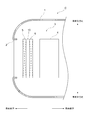
- FIG. 1 is a diagram schematically illustrating a schematic configuration of a vehicle.
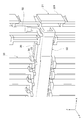
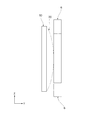
- FIG. 2 is a perspective view illustrating a perspective structure of the shutter device according to the embodiment.
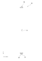
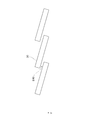
- FIG. 3 is a side view showing a side structure of the blade of the embodiment.
- FIG. 4 is an enlarged view showing an enlarged structure around a connection portion between a link member and a shaft in the shutter device of the embodiment.
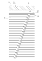
- FIG. 5 is a diagram schematically illustrating an example of deformation of a blade in the shutter device of the reference example.
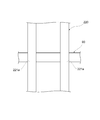
- FIG. 6 is a diagram schematically illustrating an example of a modification of the frame in the shutter device of the reference example.
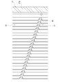
- FIG. 7 is a diagram schematically illustrating an example of deformation of a blade in the shutter device of the reference example.
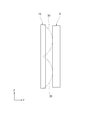
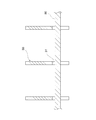
- FIG. 8 is a diagram schematically illustrating an example of a blade in a closed state in the shutter device of the reference example.
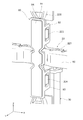
- FIG. 9 is a perspective view showing a perspective structure in which the vicinity of a bracket in the shutter device of the embodiment is enlarged.
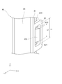
- FIG. 10 is an enlarged view showing an enlarged structure of a connection portion between the bracket and the frame in the shutter device of the embodiment.
- FIG. 11 is a perspective view illustrating a perspective structure of a blade and a rod-shaped member according to the embodiment.
- FIG. 12 is an enlarged view showing an enlarged structure of a connection portion between the center of the rod-shaped member and the frame in the shutter device of the embodiment.
- FIG. 13 is a cross-sectional view illustrating a cross-sectional structure of the blade and the rod-shaped member according to the embodiment.
- FIG. 14 is a perspective view illustrating a perspective structure of the blade and the rod-shaped member of the embodiment.
- FIG. 15 is a cross-sectional view illustrating a cross-sectional structure of the blade and the rod-shaped member according to the embodiment.
- FIG. 16 is a side view showing a side structure of a shutter device according to another embodiment.
- a grill opening 2 is provided in front of the body 1 of the vehicle C.
- the air in front of the vehicle body 1 is introduced into the engine room 3 of the vehicle body 1 through the grill opening 2.
- heat exchangers 5, 6 such as radiators and condensers are arranged in the engine room 3, in addition to the engine 4 of the vehicle C.
- the radiator radiates the cooling water by performing heat exchange between cooling water for cooling the engine 4 and air introduced from the grill opening 2.
- the condenser is a component of a refrigeration cycle of an air conditioner mounted on the vehicle C, and performs heat exchange between a refrigerant circulating in the refrigeration cycle and air introduced from the grill opening 2. Dissipates the refrigerant.
- the heat exchangers 5, 6 are arranged between the grill opening 2 and the engine 4.
- a shutter device 10 is provided between the heat exchangers 5 and 6, which is capable of temporarily blocking the flow of air from the grill opening 2 to the engine room 3.
- the shutter device 10 enables early warm-up of the engine 4 by, for example, temporarily blocking the flow of air from the grill opening 2 to the engine room 3 when the engine 4 is cold started. Further, the shutter device 10 improves the aerodynamic performance of the vehicle C, for example, by temporarily blocking the flow of air to the engine room 3 when the vehicle C runs at high speed.
- the shutter device 10 includes a frame 20, a plurality of blades 30, an actuator device 40, a shaft 50, and a link member 60.
- the frame 20 has a frame main body 21 formed in a rectangular frame shape, and a reinforcing frame piece 22 for reinforcing the frame main body 21.
- the frame 20 is formed of, for example, a resin material.
- the frame body 21 has an upper frame piece 210, a lower frame piece 211, a right frame piece 212, and a left frame piece 213. Air introduced from the grill opening 2 shown in FIG. 1 flows through the space in the frame of the frame body 21.
- the respective longitudinal directions of the upper frame piece 210 and the lower frame piece 211 are also referred to as the X-axis direction
- the respective longitudinal directions of the right frame piece 212 and the left frame piece 213 are also referred to as the Z-axis direction
- the Z-axis direction corresponds to the vertical direction and the vehicle vertical direction.
- a direction orthogonal to both the X-axis direction and the Z-axis direction is also referred to as a Y-axis direction. Since the Y-axis direction corresponds to the air flow direction, hereinafter, the Y-axis direction is also referred to as “air flow direction Y”.
- the reinforcing frame pieces 22 are arranged in a cross shape within the frame of the frame body 21.
- the reinforcing frame piece 22 includes upper and lower reinforcing frame pieces 220 provided so as to connect between the respective central portions of the upper frame piece 210 and the lower frame piece 211, and the right frame piece 212 and the left frame piece 213, respectively. And left and right reinforcing frame pieces 221 provided so as to connect between the central portions thereof.
- the inside of the frame of the frame 20 is partitioned into four regions by the reinforcing frame pieces 22.
- the blade 30 has shaft portions 32 and 33 at both ends in the longitudinal direction.
- the shaft portions 32 and 33 are portions rotatably supported by the frame 20.
- the blade 30 has a connecting portion 34 at an end where the shaft portion 33 is formed.
- the connecting portion 34 is a portion to which the link member 60 is connected.
- the blade 30 opens and closes around the shaft portions 32 and 33 by a force applied to the connecting portion 34 via the link member 60.
- a notch 31 is formed at the center of the blade 30. In FIG. 2, the notch 31 of the blade 30 is not shown.
- the plurality of blades 30 are arranged in four regions within the frame of the frame 20. In the four regions within the frame of the frame 20, the plurality of blades 30 are arranged so as to have a longitudinal direction in the Z-axis direction, and are arranged side by side in the X-axis direction.
- each of the blades 30 disposed between the upper frame piece 210 and the left and right reinforcing frame pieces 221 has a shaft portion 32 provided at the upper end thereof rotatably supported by the upper frame piece 210.
- the shaft portion 33 provided at the lower end is rotatably supported by the left and right reinforcing frame pieces 221.
- each of the blades 30 disposed between the lower frame piece 211 and the left and right reinforcing frame pieces 221 has a shaft portion 33 provided at the upper end thereof rotatable by the left and right reinforcing frame pieces 221.
- a shaft portion 32 provided at a lower end thereof is rotatably supported by the lower frame piece 211.
- the link member 60 is further attached to the left and right reinforcing frame pieces 221.
- the link member 60 is formed to extend in the X-axis direction.
- a connecting portion 34 formed at one end of each blade 30 is connected to the link member 60.
- the lower end of the shaft 50 is connected to one end of the link member 60.
- the shaft 50 is disposed along the right frame piece 212 upward from the center of the right frame piece 212.
- the upper end of the shaft 50 protrudes from the upper surface of one end of the upper frame piece 210.
- a gear 51 is formed at the upper end of the shaft 50.
- the actuator device 40 is fixed above one end of the upper frame piece 210 by a screw or the like.
- the actuator device 40 has a drive shaft meshed with the gear 51 of the shaft 50, and rotates the shaft 50 based on power supply.
- the link member 60 is relatively displaced in the X-axis direction with respect to the left and right reinforcing frame pieces 221 by the rotation of the shaft 50, the plurality of blades 30 open and close. That is, the link member 60 opens and closes the plurality of blades 30 by transmitting the rotational force of the shaft 50 to the plurality of blades 30.
- the plurality of blades 30 are in the open state, a gap is formed between the blades 30, so that air can flow from the grill opening 2 into the engine room 3 through the gap.
- the plurality of blades 30 are in the closed state, the gap between the blades 30 is closed, so that the flow of air from the grill opening 2 to the engine room 3 is temporarily interrupted.
- the blades 30 are moved as shown by a two-dot chain line in FIG. It may be deformed so as to bend in the air flow direction Y.
- the frame 20 may be deformed so as to bend in the air flow direction Y as shown by a two-dot chain line in FIG.
- the blade 30 may slide off the frame 20.
- the frame 20 and the blade 30 are deformed as shown in FIGS. 5 and 6, the frame 20 and the blade 30 are attached to the heat exchanger 6 disposed on the downstream side in the air flow direction Y with respect to the shutter device 10. The contact may cause damage to the frame 20, the blade 30, or the heat exchanger 6.
- the heat exchanger 6 and the shutter device 10 may vibrate in the Z-axis direction due to the vibration of the vehicle C, that is, in the vertical direction of the vehicle C. Since the shape and weight of the heat exchanger 6 and the shutter device 10 are different, the heat exchanger 6 and the shutter device 10 vibrate in different modes. Therefore, the relative positional relationship between the heat exchanger 6 and the shutter device 10 is shifted. If the heat exchanger 6 is oscillating with a larger amplitude than the shutter device 10, when the frame 20 comes into contact with the heat exchanger 6 as shown in FIG. Since a large frictional force is generated at the contact portion, the frame 20 or the heat exchanger 6 may be damaged earlier than the life at the contact portion.
- Such self-excited vibration of the blade 30 causes noise.
- the self-excited vibration of the blade 30 is transmitted to another portion of the shutter device 10 and the other portion vibrates, which may cause a problem such that the wear of various parts of the shutter device 10 is promoted. .
- the bracket 80 and the rod-shaped member 90 are assembled to the frame 20. Further, the rod-shaped member 90 also functions as a member for suppressing self-excited vibration of the blade 30 as shown in FIG.
- the bracket 80 and the rod-shaped member 90 suppress the deformation of the blade 30 and the frame 20, thereby preventing the blade 30 from falling off the frame 20. That is, in the present embodiment, the bracket 80 and the rod-shaped member 90 correspond to an auxiliary member that assists the blade 30 in supporting the frame 20.
- the bracket 80 includes a connection portion between a center portion of the right frame piece 212 and a right end portion of the left and right reinforcement frame piece 221, a center portion of the left frame piece 213 and a left end of the left and right reinforcement frame piece 221. This is provided at the connection portion between the upper and lower portions and the connection portion between the center of the upper and lower reinforcement frame pieces 220 and the center of the left and right reinforcement frame pieces 221.
- brackets 80 provided at the respective portions are the same, the structure of the bracket 80 provided at the connection portion between the center of the upper and lower reinforcing frame pieces 220 and the center of the left and right reinforcing frame pieces 221 will be described below. I will explain.
- this bracket 80 is a connecting portion between the central portion of the upper and lower reinforcing frame pieces 220 and the central portion of the left and right reinforcing frame pieces 221, in other words, the central portion of the cross in the reinforcing frame pieces 22.
- the bracket 80 is formed of a resin material.
- the bracket 80 is attached to the outer surface of the reinforcing frame piece 22 located on the downstream side in the air flow direction Y.
- the bracket 80 has a base portion 81 formed in a plate shape, and engagement portions 82 and 83 formed to extend from each of both side surfaces of the base portion 81 in a direction parallel to the Y-axis direction. .
- Claws 223 are formed on both sides in the X-axis direction at positions above the connection portions with the left and right reinforcement frame pieces 221 in the upper and lower reinforcement frame pieces 220.
- the engaging portion 82 of the bracket 80 is engaged with the claw portion 223 in the Y-axis direction.
- the length L1 of the hole of the engaging portion 82 of the bracket 80 in the Z-axis direction is longer than the length L2 of the claw portion 223 in the Z-axis direction.
- a gap S20 is formed between the upper inner wall surface of the engaging portion 82 of the bracket 80 and the claw portion 223 of the reinforcing frame piece 22.
- a gap S21 is also formed between the lower inner wall surface of the engaging portion 82 of the bracket 80 and the claw portion 223 of the reinforcing frame piece 22. Due to these gaps S20 and S21.
- the bracket 80 can be relatively displaced in the Z-axis direction with respect to the reinforcing frame piece 22.
- a similar claw portion 224 with which the engaging portion 83 of the bracket 80 engages is provided below the connection portion between the upper and lower reinforcing frame pieces 220 and the left and right reinforcing frame pieces 221. It is formed on both sides in the axial direction.
- the base portion 81 of the bracket 80 is arranged to face the center of the link member 60. Thus, the bracket 80 holds the central portion of the link member 60 to the left and right reinforcing frame pieces 221.
- the bracket 80 holds the link member 60 with respect to the left and right reinforcing frame pieces 221. Accordingly, the sliding of the link member 60 from the left and right reinforcing frame pieces 221 can be suppressed, and as a result, the sliding of the blade 30 from the frame 20 can be suppressed.
- the bracket 80 functions as an auxiliary member that suppresses the blade 30 from slipping off the frame 20.
- an elastic body 84 such as rubber is integrally formed on the surface of the bracket 80. That is, the bracket 80 is formed of a two-color molded product formed of a resin material and an elastic material such as rubber.
- the rod-shaped member 90 has a plurality of blades 30 arranged in a region facing the center of the plurality of blades 30 arranged in the region above the frame 20 and a plurality of blades 30 arranged in the region below the frame 20. And at a position facing the center of the. As shown in FIG. 11, one end of the rod-shaped member 90 is inserted and fixed in an insertion hole 212a formed in the right frame piece 212.
- the other end of the rod-shaped member 90 is inserted and fixed in an insertion hole formed in the left frame piece 213.
- the central portion of the rod-shaped member 90 is held by the left and right reinforcing frame pieces 221 by being inserted into insertion holes 221 a formed in the left and right reinforcing frame pieces 221.
- the bar-shaped member 90 is arranged at a position facing the notch 31 of each blade 30. As shown in FIGS. 14 and 15, when each blade 30 is in the open state, the rod-shaped member 90 is inserted into the notch 31 of each blade 30.
- the rod-shaped member 90 is attached to the right frame piece 212, the left frame piece 213, and the left and right reinforcing frame piece 221 to suppress deformation of the frame 20 downstream in the air flow direction Y, thereby allowing the rod member 90 to move from the frame 20.
- each blade 30 when each blade 30 is in the closed state, and when each blade 30 is deformed downstream in the air flow direction Y due to ram pressure, self-excited vibration, or the like, each blade 30 It comes into contact with the rod-shaped member 90. Thereby, further deformation of each blade 30 is regulated by the rod-shaped member 90.
- the rod-shaped member 90 functions as an auxiliary member that suppresses the sliding of the blade 30 from the frame 20 by further suppressing the deformation of the blade 30 to the downstream side in the air flow direction Y in this manner.
- each blade 30 comes into contact with the heat exchanger 6 arranged downstream in the air flow direction Y. Can be avoided. Further, since each blade 30 comes into contact with the rod-shaped member 90, the self-excited vibration of each blade 30 can be suppressed, so that noise generated due to the self-excited vibration of each blade 30 and various components of the shutter device 10 are provided. Can be suppressed.
- the most easily deformable portion of the frame 20 is the central portion of the frame 20. If the central portion of the frame 20 is greatly deformed downstream in the air flow direction Y, the bracket 80 provided at the central portion of the frame 20 comes into contact with the heat exchanger 6. At this time, since the elastic body 84 provided on the surface of the bracket 80 comes into contact with the heat exchanger 6, the impact force applied to the frame 20 when the frame 20 comes into contact with the heat exchanger 6 can be absorbed by the elastic body 84. it can. Therefore, the impact force applied to the frame 20 can be reduced.
- the bracket 80 comes into contact with the vibrating heat exchanger 6 in a situation where the heat exchanger 6 is vibrating with the vibration of the vehicle C, the elastic body 84 of the bracket 80 and the heat exchanger 6 6, the bracket 80 is displaced in the vertical direction of the vehicle C, that is, in the Z-axis direction, integrally with the heat exchanger 6.
- a gap is formed in the Z-axis direction between the engaging portion 82 of the bracket 80 and the claw portion 223 of the frame 20, and between the engaging portion 83 of the bracket 80 and the claw portion 224 of the frame 20. Therefore, the bracket 80 can be displaced relative to the frame 20.
- the relative displacement of the bracket 80 with respect to the frame 20 allows the bracket 80 to absorb the difference in displacement between the vibrating heat exchanger 6 and the frame 20. Can be suppressed from being applied. Therefore, it is possible to prevent the frame or the heat exchanger from being damaged early.
- the following operations and effects (1) to (12) can be obtained.
- the bracket 80 and the rod-shaped member 90 are assembled to the frame 20 to assist the blade 30 in supporting the frame 20. According to such a configuration, the sliding of the blade 30 from the frame 20 can be suppressed.
- the bracket 80 holds the link member 60 with respect to the left and right reinforcing frame pieces 221. Thereby, it is possible to suppress the blade 30 from sliding down due to the sliding of the link member 60 from the left and right reinforcing frame pieces 221.
- the bracket 80 is mounted on the outer surface of the frame 20 located on the downstream side in the air flow direction Y. According to such a configuration, the deformation of the frame 20 toward the downstream side in the air flow direction Y can be effectively suppressed by the bracket 80.
- the elastic body 84 is integrally provided on the surface of the bracket 80. Thereby, when the frame 20 comes into contact with the heat exchanger 6, the impact force applied to the frame 20 or the heat exchanger 6 can be absorbed by the elastic body 84, so that the impact force applied to the frame 20 can be reduced. it can.
- the shutter device 10 is provided with a plurality of brackets 80 and a plurality of bar-shaped members 90. Thereby, the blade 30 can be more reliably supported on the frame 20.
- the brackets 80 arranged at the right ends of the left and right reinforcing frame pieces 221 further have a function of holding the shaft 50 with respect to the frame 20. According to such a configuration, the bracket 80 can prevent the shaft 50 from falling off from the frame 20.
- the rod-shaped member 90 further suppresses the deformation of the blade 30 to the downstream side in the air flow direction Y. According to such a configuration, the rod 30 can prevent the blade 30 from contacting the heat exchanger 6 adjacent to the shutter device 10. In addition, since the self-excited vibration of the blade 30 can be suppressed by the rod-shaped member 90, noise generated on the blade 30 and wear of parts due to the self-excited vibration can be suppressed.
- the rod-shaped member 90 is disposed to face the plurality of blades 30 on the downstream side in the air flow direction Y, is formed to extend in the X-axis direction, and is assembled to the frame 20. According to such a rod-shaped member 90, a member capable of suppressing deformation of the blade 30 can be easily realized.
- the blade 30 has a notch 31 for avoiding interference with the bar-shaped member 90 when the blade 30 is in the open state. According to such a configuration, since the rod-shaped member 90 can be arranged close to the blade 30, the deformation of the blade 30 is easily suppressed by the rod-shaped member 90.
- the rod-shaped member 90 is arranged so as to face the central part in the longitudinal direction of the plurality of blades 30. According to such a configuration, since the deformation of the most easily deformable portion of the blade 30 can be suppressed by the rod-shaped member 90, the deformation of the blade 30 can be effectively suppressed.
- the bracket 80 may be assembled not only on the outer surface of the frame 20 located on the downstream side in the air flow direction, but also on the outer surface of the frame 20 located on the upstream side in the air flow direction. .
- the rod-shaped member 90 may be arrange
- one of the bracket 80 and the rod-shaped member 90 may be provided in the shutter device 10.
- the present disclosure is not limited to the above specific examples.
- the above-described specific examples in which a person skilled in the art makes appropriate design changes are also included in the scope of the present disclosure as long as they have the features of the present disclosure.
- the components included in each of the specific examples described above, and their arrangement, conditions, shapes, and the like are not limited to those illustrated, but can be appropriately changed.
- the elements included in each of the specific examples described above can be appropriately changed in combination as long as no technical inconsistency occurs.
Landscapes
- Engineering & Computer Science (AREA)
- Mechanical Engineering (AREA)
- Chemical & Material Sciences (AREA)
- Combustion & Propulsion (AREA)
- Transportation (AREA)
- Cooling, Air Intake And Gas Exhaust, And Fuel Tank Arrangements In Propulsion Units (AREA)
Priority Applications (1)
| Application Number | Priority Date | Filing Date | Title |
|---|---|---|---|
| US17/153,093 US11951824B2 (en) | 2018-07-26 | 2021-01-20 | Shutter device for vehicle |
Applications Claiming Priority (2)
| Application Number | Priority Date | Filing Date | Title |
|---|---|---|---|
| JP2018-139903 | 2018-07-26 | ||
| JP2018139903A JP7115104B2 (ja) | 2018-07-26 | 2018-07-26 | 車両のシャッタ装置 |
Related Child Applications (1)
| Application Number | Title | Priority Date | Filing Date |
|---|---|---|---|
| US17/153,093 Continuation US11951824B2 (en) | 2018-07-26 | 2021-01-20 | Shutter device for vehicle |
Publications (1)
| Publication Number | Publication Date |
|---|---|
| WO2020021963A1 true WO2020021963A1 (ja) | 2020-01-30 |
Family
ID=69181574
Family Applications (1)
| Application Number | Title | Priority Date | Filing Date |
|---|---|---|---|
| PCT/JP2019/025860 Ceased WO2020021963A1 (ja) | 2018-07-26 | 2019-06-28 | 車両のシャッタ装置 |
Country Status (3)
| Country | Link |
|---|---|
| US (1) | US11951824B2 (enExample) |
| JP (1) | JP7115104B2 (enExample) |
| WO (1) | WO2020021963A1 (enExample) |
Cited By (2)
| Publication number | Priority date | Publication date | Assignee | Title |
|---|---|---|---|---|
| WO2021181849A1 (ja) * | 2020-03-13 | 2021-09-16 | 株式会社デンソー | 車両のシャッタ装置 |
| JP7447772B2 (ja) | 2020-03-13 | 2024-03-12 | 株式会社デンソー | 車両のシャッタ装置 |
Families Citing this family (3)
| Publication number | Priority date | Publication date | Assignee | Title |
|---|---|---|---|---|
| JP7388030B2 (ja) | 2019-07-26 | 2023-11-29 | 株式会社デンソー | 車両のシャッタ装置 |
| JP2021037877A (ja) * | 2019-09-04 | 2021-03-11 | 株式会社デンソー | シャッター装置 |
| JP7336338B2 (ja) * | 2019-09-27 | 2023-08-31 | 株式会社デンソー | 車両のシャッタ装置 |
Citations (5)
| Publication number | Priority date | Publication date | Assignee | Title |
|---|---|---|---|---|
| JP2015217827A (ja) * | 2014-05-19 | 2015-12-07 | シロキ工業株式会社 | 車両用シャッター装置 |
| JP2016147553A (ja) * | 2015-02-10 | 2016-08-18 | 本田技研工業株式会社 | 車両のシャッタ開閉機構 |
| JP2016205117A (ja) * | 2015-04-27 | 2016-12-08 | コベルコ建機株式会社 | 建設機械 |
| JP2017043174A (ja) * | 2015-08-25 | 2017-03-02 | アイシン精機株式会社 | グリルシャッタ装置 |
| JP2017185991A (ja) * | 2016-03-31 | 2017-10-12 | 株式会社デンソー | シャッター装置及びシャッター装置の製造方法 |
Family Cites Families (4)
| Publication number | Priority date | Publication date | Assignee | Title |
|---|---|---|---|---|
| FR2906759B1 (fr) * | 2006-10-09 | 2011-04-01 | Peugeot Citroen Automobiles Sa | Aerateur pour vehicule automobile |
| US9902256B2 (en) | 2014-05-19 | 2018-02-27 | Shiroki Corporation | Vehicular shutter device |
| JP2016055719A (ja) | 2014-09-08 | 2016-04-21 | カルソニックカンセイ株式会社 | グリルシャッター |
| JP2019100389A (ja) | 2017-11-29 | 2019-06-24 | 株式会社デンソー | 連結部材、構造体モジュール |
-
2018
- 2018-07-26 JP JP2018139903A patent/JP7115104B2/ja active Active
-
2019
- 2019-06-28 WO PCT/JP2019/025860 patent/WO2020021963A1/ja not_active Ceased
-
2021
- 2021-01-20 US US17/153,093 patent/US11951824B2/en active Active
Patent Citations (5)
| Publication number | Priority date | Publication date | Assignee | Title |
|---|---|---|---|---|
| JP2015217827A (ja) * | 2014-05-19 | 2015-12-07 | シロキ工業株式会社 | 車両用シャッター装置 |
| JP2016147553A (ja) * | 2015-02-10 | 2016-08-18 | 本田技研工業株式会社 | 車両のシャッタ開閉機構 |
| JP2016205117A (ja) * | 2015-04-27 | 2016-12-08 | コベルコ建機株式会社 | 建設機械 |
| JP2017043174A (ja) * | 2015-08-25 | 2017-03-02 | アイシン精機株式会社 | グリルシャッタ装置 |
| JP2017185991A (ja) * | 2016-03-31 | 2017-10-12 | 株式会社デンソー | シャッター装置及びシャッター装置の製造方法 |
Cited By (2)
| Publication number | Priority date | Publication date | Assignee | Title |
|---|---|---|---|---|
| WO2021181849A1 (ja) * | 2020-03-13 | 2021-09-16 | 株式会社デンソー | 車両のシャッタ装置 |
| JP7447772B2 (ja) | 2020-03-13 | 2024-03-12 | 株式会社デンソー | 車両のシャッタ装置 |
Also Published As
| Publication number | Publication date |
|---|---|
| US11951824B2 (en) | 2024-04-09 |
| JP7115104B2 (ja) | 2022-08-09 |
| US20210138892A1 (en) | 2021-05-13 |
| JP2020015426A (ja) | 2020-01-30 |
Similar Documents
| Publication | Publication Date | Title |
|---|---|---|
| WO2020021963A1 (ja) | 車両のシャッタ装置 | |
| JP4127112B2 (ja) | 車両のフロントエンド構造 | |
| JP2012035829A (ja) | 車両用可動グリルシャッター | |
| US10245939B2 (en) | Grille shutter device | |
| JP2009162127A (ja) | 車両用送風装置 | |
| KR101576970B1 (ko) | 쿨링모듈 | |
| JP5761086B2 (ja) | 車両 | |
| KR101362332B1 (ko) | 프론트 엔드 모듈 | |
| WO2020045312A1 (en) | Cooling apparatus for vehicle | |
| JPH08165928A (ja) | 熱交換器用ファンシュラウド | |
| US10816281B2 (en) | Cooling module supporting structure | |
| KR20150062322A (ko) | 차량의 액티브 에어 플랩 | |
| JP7358820B2 (ja) | 車両のシャッタ装置 | |
| JP7336338B2 (ja) | 車両のシャッタ装置 | |
| WO2020022057A1 (ja) | 組立体 | |
| JP7447772B2 (ja) | 車両のシャッタ装置 | |
| KR102145514B1 (ko) | 쿨링모듈 장착구조 | |
| CN223173915U (zh) | 减振支架及汽车 | |
| JP7567283B2 (ja) | 車両のシャッタ装置 | |
| KR20110097165A (ko) | 축류팬 | |
| KR20150070770A (ko) | 액티브 에어 플랩 | |
| KR20110048273A (ko) | 차량 쿨링팬 구동용 풀리 어셈블리 | |
| KR102325024B1 (ko) | 차량용 캐리어 | |
| JP3336915B2 (ja) | 空調用コンデンサ、空調用コンデンサの支持構造および車両用冷却装置 | |
| WO2021020108A1 (ja) | 車両のシャッタ装置 |
Legal Events
| Date | Code | Title | Description |
|---|---|---|---|
| 121 | Ep: the epo has been informed by wipo that ep was designated in this application |
Ref document number: 19841137 Country of ref document: EP Kind code of ref document: A1 |
|
| NENP | Non-entry into the national phase |
Ref country code: DE |
|
| 122 | Ep: pct application non-entry in european phase |
Ref document number: 19841137 Country of ref document: EP Kind code of ref document: A1 |