WO2020021963A1 - 車両のシャッタ装置 - Google Patents
車両のシャッタ装置 Download PDFInfo
- Publication number
- WO2020021963A1 WO2020021963A1 PCT/JP2019/025860 JP2019025860W WO2020021963A1 WO 2020021963 A1 WO2020021963 A1 WO 2020021963A1 JP 2019025860 W JP2019025860 W JP 2019025860W WO 2020021963 A1 WO2020021963 A1 WO 2020021963A1
- Authority
- WO
- WIPO (PCT)
- Prior art keywords
- frame
- blade
- shutter device
- blades
- vehicle
- Prior art date
- Legal status (The legal status is an assumption and is not a legal conclusion. Google has not performed a legal analysis and makes no representation as to the accuracy of the status listed.)
- Ceased
Links
Images




Classifications
-
- B—PERFORMING OPERATIONS; TRANSPORTING
- B60—VEHICLES IN GENERAL
- B60K—ARRANGEMENT OR MOUNTING OF PROPULSION UNITS OR OF TRANSMISSIONS IN VEHICLES; ARRANGEMENT OR MOUNTING OF PLURAL DIVERSE PRIME-MOVERS IN VEHICLES; AUXILIARY DRIVES FOR VEHICLES; INSTRUMENTATION OR DASHBOARDS FOR VEHICLES; ARRANGEMENTS IN CONNECTION WITH COOLING, AIR INTAKE, GAS EXHAUST OR FUEL SUPPLY OF PROPULSION UNITS IN VEHICLES
- B60K11/00—Arrangement in connection with cooling of propulsion units
- B60K11/02—Arrangement in connection with cooling of propulsion units with liquid cooling
- B60K11/04—Arrangement or mounting of radiators, radiator shutters, or radiator blinds
-
- B—PERFORMING OPERATIONS; TRANSPORTING
- B60—VEHICLES IN GENERAL
- B60K—ARRANGEMENT OR MOUNTING OF PROPULSION UNITS OR OF TRANSMISSIONS IN VEHICLES; ARRANGEMENT OR MOUNTING OF PLURAL DIVERSE PRIME-MOVERS IN VEHICLES; AUXILIARY DRIVES FOR VEHICLES; INSTRUMENTATION OR DASHBOARDS FOR VEHICLES; ARRANGEMENTS IN CONNECTION WITH COOLING, AIR INTAKE, GAS EXHAUST OR FUEL SUPPLY OF PROPULSION UNITS IN VEHICLES
- B60K11/00—Arrangement in connection with cooling of propulsion units
- B60K11/08—Air inlets for cooling; Shutters or blinds therefor
- B60K11/085—Air inlets for cooling; Shutters or blinds therefor with adjustable shutters or blinds
-
- B—PERFORMING OPERATIONS; TRANSPORTING
- B60—VEHICLES IN GENERAL
- B60R—VEHICLES, VEHICLE FITTINGS, OR VEHICLE PARTS, NOT OTHERWISE PROVIDED FOR
- B60R19/00—Wheel guards; Radiator guards, e.g. grilles; Obstruction removers; Fittings damping bouncing force in collisions
- B60R19/52—Radiator or grille guards ; Radiator grilles
-
- Y—GENERAL TAGGING OF NEW TECHNOLOGICAL DEVELOPMENTS; GENERAL TAGGING OF CROSS-SECTIONAL TECHNOLOGIES SPANNING OVER SEVERAL SECTIONS OF THE IPC; TECHNICAL SUBJECTS COVERED BY FORMER USPC CROSS-REFERENCE ART COLLECTIONS [XRACs] AND DIGESTS
- Y02—TECHNOLOGIES OR APPLICATIONS FOR MITIGATION OR ADAPTATION AGAINST CLIMATE CHANGE
- Y02T—CLIMATE CHANGE MITIGATION TECHNOLOGIES RELATED TO TRANSPORTATION
- Y02T10/00—Road transport of goods or passengers
- Y02T10/80—Technologies aiming to reduce greenhouse gasses emissions common to all road transportation technologies
- Y02T10/88—Optimized components or subsystems, e.g. lighting, actively controlled glasses
Definitions
- the present disclosure relates to a shutter device for a vehicle.
- the air introduced into the engine room from the grill opening is used to radiate heat from the radiator through which engine cooling water flows and from the condenser in the vehicle air conditioner.
- a shutter device capable of temporarily blocking the flow of air from the grill opening to the engine room.
- the shutter device enables early warm-up of the engine, for example, by temporarily blocking the flow of air into the engine room when the engine is cold started. Further, the shutter device improves the aerodynamic performance of the vehicle, for example, by temporarily blocking the inflow of air into the engine room when the vehicle is running at high speed.
- a shutter device for example, there is a shutter device described in Patent Document 1.
- the shutter device described in Patent Literature 1 includes a plurality of blades having shaft portions at both ends, and a frame that rotatably fits and supports the shaft portions of the blades. Each blade opens and closes by rotating about its axis.
- this shutter device when the plurality of blades are in the open state, air can pass through, and when the plurality of blades are in the closed state, the flow of air through the frame is shut off.
- the space in the engine room has been reduced due to factors such as an increase in the number of devices installed in the engine room of the vehicle. Therefore, a reduction in the mounting space of a shutter device for a vehicle is also required.
- the inventors are considering placing a shutter device in a narrow gap between two heat exchangers such as a radiator and a condenser of an air conditioner. When arranging the shutter device in such a place, it is necessary to reduce the thickness of the shutter device.
- the shutter device when the shutter device is in the closed state, the running wind of the vehicle hits the blade, and ram pressure is generated on the blade.
- the strength of the frame is reduced due to the reduction in the thickness of the shutter device, the force applied to the blade by the ram pressure is transmitted to the frame, so that the frame is easily deformed downstream in the air flow direction. If the frame is deformed downstream in the air flow direction, the blades may slide off the frame. Also, when the blade is deformed by the ram pressure, the blade may similarly slide down from the frame.
- An object of the present disclosure is to provide a vehicle shutter device capable of suppressing the blade from slipping off a frame.
- a vehicle shutter device includes a frame, a plurality of blades, an actuator device, and an auxiliary member.
- the frame is formed in a frame shape, and air introduced from a grill opening of the vehicle flows through a space in the frame.
- the blade is rotatably supported by the frame and opens and closes a space in the frame of the frame.
- the actuator device opens and closes the blade.
- the auxiliary member is assembled to the frame and assists in supporting the blade with respect to the frame.
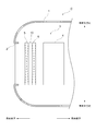
- FIG. 1 is a diagram schematically illustrating a schematic configuration of a vehicle.
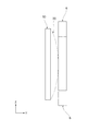
- FIG. 2 is a perspective view illustrating a perspective structure of the shutter device according to the embodiment.
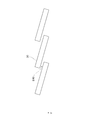
- FIG. 3 is a side view showing a side structure of the blade of the embodiment.
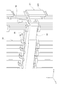
- FIG. 4 is an enlarged view showing an enlarged structure around a connection portion between a link member and a shaft in the shutter device of the embodiment.
- FIG. 5 is a diagram schematically illustrating an example of deformation of a blade in the shutter device of the reference example.
- FIG. 6 is a diagram schematically illustrating an example of a modification of the frame in the shutter device of the reference example.
- FIG. 7 is a diagram schematically illustrating an example of deformation of a blade in the shutter device of the reference example.
- FIG. 8 is a diagram schematically illustrating an example of a blade in a closed state in the shutter device of the reference example.
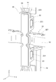
- FIG. 9 is a perspective view showing a perspective structure in which the vicinity of a bracket in the shutter device of the embodiment is enlarged.
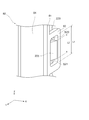
- FIG. 10 is an enlarged view showing an enlarged structure of a connection portion between the bracket and the frame in the shutter device of the embodiment.
- FIG. 11 is a perspective view illustrating a perspective structure of a blade and a rod-shaped member according to the embodiment.
- FIG. 12 is an enlarged view showing an enlarged structure of a connection portion between the center of the rod-shaped member and the frame in the shutter device of the embodiment.
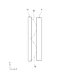
- FIG. 13 is a cross-sectional view illustrating a cross-sectional structure of the blade and the rod-shaped member according to the embodiment.
- FIG. 14 is a perspective view illustrating a perspective structure of the blade and the rod-shaped member of the embodiment.
- FIG. 15 is a cross-sectional view illustrating a cross-sectional structure of the blade and the rod-shaped member according to the embodiment.
- FIG. 16 is a side view showing a side structure of a shutter device according to another embodiment.
- a grill opening 2 is provided in front of the body 1 of the vehicle C.
- the air in front of the vehicle body 1 is introduced into the engine room 3 of the vehicle body 1 through the grill opening 2.
- heat exchangers 5, 6 such as radiators and condensers are arranged in the engine room 3, in addition to the engine 4 of the vehicle C.
- the radiator radiates the cooling water by performing heat exchange between cooling water for cooling the engine 4 and air introduced from the grill opening 2.
- the condenser is a component of a refrigeration cycle of an air conditioner mounted on the vehicle C, and performs heat exchange between a refrigerant circulating in the refrigeration cycle and air introduced from the grill opening 2. Dissipates the refrigerant.
- the heat exchangers 5, 6 are arranged between the grill opening 2 and the engine 4.
- a shutter device 10 is provided between the heat exchangers 5 and 6, which is capable of temporarily blocking the flow of air from the grill opening 2 to the engine room 3.
- the shutter device 10 enables early warm-up of the engine 4 by, for example, temporarily blocking the flow of air from the grill opening 2 to the engine room 3 when the engine 4 is cold started. Further, the shutter device 10 improves the aerodynamic performance of the vehicle C, for example, by temporarily blocking the flow of air to the engine room 3 when the vehicle C runs at high speed.
- the shutter device 10 includes a frame 20, a plurality of blades 30, an actuator device 40, a shaft 50, and a link member 60.
- the frame 20 has a frame main body 21 formed in a rectangular frame shape, and a reinforcing frame piece 22 for reinforcing the frame main body 21.
- the frame 20 is formed of, for example, a resin material.
- the frame body 21 has an upper frame piece 210, a lower frame piece 211, a right frame piece 212, and a left frame piece 213. Air introduced from the grill opening 2 shown in FIG. 1 flows through the space in the frame of the frame body 21.
- the respective longitudinal directions of the upper frame piece 210 and the lower frame piece 211 are also referred to as the X-axis direction
- the respective longitudinal directions of the right frame piece 212 and the left frame piece 213 are also referred to as the Z-axis direction
- the Z-axis direction corresponds to the vertical direction and the vehicle vertical direction.
- a direction orthogonal to both the X-axis direction and the Z-axis direction is also referred to as a Y-axis direction. Since the Y-axis direction corresponds to the air flow direction, hereinafter, the Y-axis direction is also referred to as “air flow direction Y”.
- the reinforcing frame pieces 22 are arranged in a cross shape within the frame of the frame body 21.
- the reinforcing frame piece 22 includes upper and lower reinforcing frame pieces 220 provided so as to connect between the respective central portions of the upper frame piece 210 and the lower frame piece 211, and the right frame piece 212 and the left frame piece 213, respectively. And left and right reinforcing frame pieces 221 provided so as to connect between the central portions thereof.
- the inside of the frame of the frame 20 is partitioned into four regions by the reinforcing frame pieces 22.
- the blade 30 has shaft portions 32 and 33 at both ends in the longitudinal direction.
- the shaft portions 32 and 33 are portions rotatably supported by the frame 20.
- the blade 30 has a connecting portion 34 at an end where the shaft portion 33 is formed.
- the connecting portion 34 is a portion to which the link member 60 is connected.
- the blade 30 opens and closes around the shaft portions 32 and 33 by a force applied to the connecting portion 34 via the link member 60.
- a notch 31 is formed at the center of the blade 30. In FIG. 2, the notch 31 of the blade 30 is not shown.
- the plurality of blades 30 are arranged in four regions within the frame of the frame 20. In the four regions within the frame of the frame 20, the plurality of blades 30 are arranged so as to have a longitudinal direction in the Z-axis direction, and are arranged side by side in the X-axis direction.
- each of the blades 30 disposed between the upper frame piece 210 and the left and right reinforcing frame pieces 221 has a shaft portion 32 provided at the upper end thereof rotatably supported by the upper frame piece 210.
- the shaft portion 33 provided at the lower end is rotatably supported by the left and right reinforcing frame pieces 221.
- each of the blades 30 disposed between the lower frame piece 211 and the left and right reinforcing frame pieces 221 has a shaft portion 33 provided at the upper end thereof rotatable by the left and right reinforcing frame pieces 221.
- a shaft portion 32 provided at a lower end thereof is rotatably supported by the lower frame piece 211.
- the link member 60 is further attached to the left and right reinforcing frame pieces 221.
- the link member 60 is formed to extend in the X-axis direction.
- a connecting portion 34 formed at one end of each blade 30 is connected to the link member 60.
- the lower end of the shaft 50 is connected to one end of the link member 60.
- the shaft 50 is disposed along the right frame piece 212 upward from the center of the right frame piece 212.
- the upper end of the shaft 50 protrudes from the upper surface of one end of the upper frame piece 210.
- a gear 51 is formed at the upper end of the shaft 50.
- the actuator device 40 is fixed above one end of the upper frame piece 210 by a screw or the like.
- the actuator device 40 has a drive shaft meshed with the gear 51 of the shaft 50, and rotates the shaft 50 based on power supply.
- the link member 60 is relatively displaced in the X-axis direction with respect to the left and right reinforcing frame pieces 221 by the rotation of the shaft 50, the plurality of blades 30 open and close. That is, the link member 60 opens and closes the plurality of blades 30 by transmitting the rotational force of the shaft 50 to the plurality of blades 30.
- the plurality of blades 30 are in the open state, a gap is formed between the blades 30, so that air can flow from the grill opening 2 into the engine room 3 through the gap.
- the plurality of blades 30 are in the closed state, the gap between the blades 30 is closed, so that the flow of air from the grill opening 2 to the engine room 3 is temporarily interrupted.
- the blades 30 are moved as shown by a two-dot chain line in FIG. It may be deformed so as to bend in the air flow direction Y.
- the frame 20 may be deformed so as to bend in the air flow direction Y as shown by a two-dot chain line in FIG.
- the blade 30 may slide off the frame 20.
- the frame 20 and the blade 30 are deformed as shown in FIGS. 5 and 6, the frame 20 and the blade 30 are attached to the heat exchanger 6 disposed on the downstream side in the air flow direction Y with respect to the shutter device 10. The contact may cause damage to the frame 20, the blade 30, or the heat exchanger 6.
- the heat exchanger 6 and the shutter device 10 may vibrate in the Z-axis direction due to the vibration of the vehicle C, that is, in the vertical direction of the vehicle C. Since the shape and weight of the heat exchanger 6 and the shutter device 10 are different, the heat exchanger 6 and the shutter device 10 vibrate in different modes. Therefore, the relative positional relationship between the heat exchanger 6 and the shutter device 10 is shifted. If the heat exchanger 6 is oscillating with a larger amplitude than the shutter device 10, when the frame 20 comes into contact with the heat exchanger 6 as shown in FIG. Since a large frictional force is generated at the contact portion, the frame 20 or the heat exchanger 6 may be damaged earlier than the life at the contact portion.
- Such self-excited vibration of the blade 30 causes noise.
- the self-excited vibration of the blade 30 is transmitted to another portion of the shutter device 10 and the other portion vibrates, which may cause a problem such that the wear of various parts of the shutter device 10 is promoted. .
- the bracket 80 and the rod-shaped member 90 are assembled to the frame 20. Further, the rod-shaped member 90 also functions as a member for suppressing self-excited vibration of the blade 30 as shown in FIG.
- the bracket 80 and the rod-shaped member 90 suppress the deformation of the blade 30 and the frame 20, thereby preventing the blade 30 from falling off the frame 20. That is, in the present embodiment, the bracket 80 and the rod-shaped member 90 correspond to an auxiliary member that assists the blade 30 in supporting the frame 20.
- the bracket 80 includes a connection portion between a center portion of the right frame piece 212 and a right end portion of the left and right reinforcement frame piece 221, a center portion of the left frame piece 213 and a left end of the left and right reinforcement frame piece 221. This is provided at the connection portion between the upper and lower portions and the connection portion between the center of the upper and lower reinforcement frame pieces 220 and the center of the left and right reinforcement frame pieces 221.
- brackets 80 provided at the respective portions are the same, the structure of the bracket 80 provided at the connection portion between the center of the upper and lower reinforcing frame pieces 220 and the center of the left and right reinforcing frame pieces 221 will be described below. I will explain.
- this bracket 80 is a connecting portion between the central portion of the upper and lower reinforcing frame pieces 220 and the central portion of the left and right reinforcing frame pieces 221, in other words, the central portion of the cross in the reinforcing frame pieces 22.
- the bracket 80 is formed of a resin material.
- the bracket 80 is attached to the outer surface of the reinforcing frame piece 22 located on the downstream side in the air flow direction Y.
- the bracket 80 has a base portion 81 formed in a plate shape, and engagement portions 82 and 83 formed to extend from each of both side surfaces of the base portion 81 in a direction parallel to the Y-axis direction. .
- Claws 223 are formed on both sides in the X-axis direction at positions above the connection portions with the left and right reinforcement frame pieces 221 in the upper and lower reinforcement frame pieces 220.
- the engaging portion 82 of the bracket 80 is engaged with the claw portion 223 in the Y-axis direction.
- the length L1 of the hole of the engaging portion 82 of the bracket 80 in the Z-axis direction is longer than the length L2 of the claw portion 223 in the Z-axis direction.
- a gap S20 is formed between the upper inner wall surface of the engaging portion 82 of the bracket 80 and the claw portion 223 of the reinforcing frame piece 22.
- a gap S21 is also formed between the lower inner wall surface of the engaging portion 82 of the bracket 80 and the claw portion 223 of the reinforcing frame piece 22. Due to these gaps S20 and S21.
- the bracket 80 can be relatively displaced in the Z-axis direction with respect to the reinforcing frame piece 22.
- a similar claw portion 224 with which the engaging portion 83 of the bracket 80 engages is provided below the connection portion between the upper and lower reinforcing frame pieces 220 and the left and right reinforcing frame pieces 221. It is formed on both sides in the axial direction.
- the base portion 81 of the bracket 80 is arranged to face the center of the link member 60. Thus, the bracket 80 holds the central portion of the link member 60 to the left and right reinforcing frame pieces 221.
- the bracket 80 holds the link member 60 with respect to the left and right reinforcing frame pieces 221. Accordingly, the sliding of the link member 60 from the left and right reinforcing frame pieces 221 can be suppressed, and as a result, the sliding of the blade 30 from the frame 20 can be suppressed.
- the bracket 80 functions as an auxiliary member that suppresses the blade 30 from slipping off the frame 20.
- an elastic body 84 such as rubber is integrally formed on the surface of the bracket 80. That is, the bracket 80 is formed of a two-color molded product formed of a resin material and an elastic material such as rubber.
- the rod-shaped member 90 has a plurality of blades 30 arranged in a region facing the center of the plurality of blades 30 arranged in the region above the frame 20 and a plurality of blades 30 arranged in the region below the frame 20. And at a position facing the center of the. As shown in FIG. 11, one end of the rod-shaped member 90 is inserted and fixed in an insertion hole 212a formed in the right frame piece 212.
- the other end of the rod-shaped member 90 is inserted and fixed in an insertion hole formed in the left frame piece 213.
- the central portion of the rod-shaped member 90 is held by the left and right reinforcing frame pieces 221 by being inserted into insertion holes 221 a formed in the left and right reinforcing frame pieces 221.
- the bar-shaped member 90 is arranged at a position facing the notch 31 of each blade 30. As shown in FIGS. 14 and 15, when each blade 30 is in the open state, the rod-shaped member 90 is inserted into the notch 31 of each blade 30.
- the rod-shaped member 90 is attached to the right frame piece 212, the left frame piece 213, and the left and right reinforcing frame piece 221 to suppress deformation of the frame 20 downstream in the air flow direction Y, thereby allowing the rod member 90 to move from the frame 20.
- each blade 30 when each blade 30 is in the closed state, and when each blade 30 is deformed downstream in the air flow direction Y due to ram pressure, self-excited vibration, or the like, each blade 30 It comes into contact with the rod-shaped member 90. Thereby, further deformation of each blade 30 is regulated by the rod-shaped member 90.
- the rod-shaped member 90 functions as an auxiliary member that suppresses the sliding of the blade 30 from the frame 20 by further suppressing the deformation of the blade 30 to the downstream side in the air flow direction Y in this manner.
- each blade 30 comes into contact with the heat exchanger 6 arranged downstream in the air flow direction Y. Can be avoided. Further, since each blade 30 comes into contact with the rod-shaped member 90, the self-excited vibration of each blade 30 can be suppressed, so that noise generated due to the self-excited vibration of each blade 30 and various components of the shutter device 10 are provided. Can be suppressed.
- the most easily deformable portion of the frame 20 is the central portion of the frame 20. If the central portion of the frame 20 is greatly deformed downstream in the air flow direction Y, the bracket 80 provided at the central portion of the frame 20 comes into contact with the heat exchanger 6. At this time, since the elastic body 84 provided on the surface of the bracket 80 comes into contact with the heat exchanger 6, the impact force applied to the frame 20 when the frame 20 comes into contact with the heat exchanger 6 can be absorbed by the elastic body 84. it can. Therefore, the impact force applied to the frame 20 can be reduced.
- the bracket 80 comes into contact with the vibrating heat exchanger 6 in a situation where the heat exchanger 6 is vibrating with the vibration of the vehicle C, the elastic body 84 of the bracket 80 and the heat exchanger 6 6, the bracket 80 is displaced in the vertical direction of the vehicle C, that is, in the Z-axis direction, integrally with the heat exchanger 6.
- a gap is formed in the Z-axis direction between the engaging portion 82 of the bracket 80 and the claw portion 223 of the frame 20, and between the engaging portion 83 of the bracket 80 and the claw portion 224 of the frame 20. Therefore, the bracket 80 can be displaced relative to the frame 20.
- the relative displacement of the bracket 80 with respect to the frame 20 allows the bracket 80 to absorb the difference in displacement between the vibrating heat exchanger 6 and the frame 20. Can be suppressed from being applied. Therefore, it is possible to prevent the frame or the heat exchanger from being damaged early.
- the following operations and effects (1) to (12) can be obtained.
- the bracket 80 and the rod-shaped member 90 are assembled to the frame 20 to assist the blade 30 in supporting the frame 20. According to such a configuration, the sliding of the blade 30 from the frame 20 can be suppressed.
- the bracket 80 holds the link member 60 with respect to the left and right reinforcing frame pieces 221. Thereby, it is possible to suppress the blade 30 from sliding down due to the sliding of the link member 60 from the left and right reinforcing frame pieces 221.
- the bracket 80 is mounted on the outer surface of the frame 20 located on the downstream side in the air flow direction Y. According to such a configuration, the deformation of the frame 20 toward the downstream side in the air flow direction Y can be effectively suppressed by the bracket 80.
- the elastic body 84 is integrally provided on the surface of the bracket 80. Thereby, when the frame 20 comes into contact with the heat exchanger 6, the impact force applied to the frame 20 or the heat exchanger 6 can be absorbed by the elastic body 84, so that the impact force applied to the frame 20 can be reduced. it can.
- the shutter device 10 is provided with a plurality of brackets 80 and a plurality of bar-shaped members 90. Thereby, the blade 30 can be more reliably supported on the frame 20.
- the brackets 80 arranged at the right ends of the left and right reinforcing frame pieces 221 further have a function of holding the shaft 50 with respect to the frame 20. According to such a configuration, the bracket 80 can prevent the shaft 50 from falling off from the frame 20.
- the rod-shaped member 90 further suppresses the deformation of the blade 30 to the downstream side in the air flow direction Y. According to such a configuration, the rod 30 can prevent the blade 30 from contacting the heat exchanger 6 adjacent to the shutter device 10. In addition, since the self-excited vibration of the blade 30 can be suppressed by the rod-shaped member 90, noise generated on the blade 30 and wear of parts due to the self-excited vibration can be suppressed.
- the rod-shaped member 90 is disposed to face the plurality of blades 30 on the downstream side in the air flow direction Y, is formed to extend in the X-axis direction, and is assembled to the frame 20. According to such a rod-shaped member 90, a member capable of suppressing deformation of the blade 30 can be easily realized.
- the blade 30 has a notch 31 for avoiding interference with the bar-shaped member 90 when the blade 30 is in the open state. According to such a configuration, since the rod-shaped member 90 can be arranged close to the blade 30, the deformation of the blade 30 is easily suppressed by the rod-shaped member 90.
- the rod-shaped member 90 is arranged so as to face the central part in the longitudinal direction of the plurality of blades 30. According to such a configuration, since the deformation of the most easily deformable portion of the blade 30 can be suppressed by the rod-shaped member 90, the deformation of the blade 30 can be effectively suppressed.
- the bracket 80 may be assembled not only on the outer surface of the frame 20 located on the downstream side in the air flow direction, but also on the outer surface of the frame 20 located on the upstream side in the air flow direction. .
- the rod-shaped member 90 may be arrange
- one of the bracket 80 and the rod-shaped member 90 may be provided in the shutter device 10.
- the present disclosure is not limited to the above specific examples.
- the above-described specific examples in which a person skilled in the art makes appropriate design changes are also included in the scope of the present disclosure as long as they have the features of the present disclosure.
- the components included in each of the specific examples described above, and their arrangement, conditions, shapes, and the like are not limited to those illustrated, but can be appropriately changed.
- the elements included in each of the specific examples described above can be appropriately changed in combination as long as no technical inconsistency occurs.
Landscapes
- Engineering & Computer Science (AREA)
- Mechanical Engineering (AREA)
- Chemical & Material Sciences (AREA)
- Combustion & Propulsion (AREA)
- Transportation (AREA)
- Cooling, Air Intake And Gas Exhaust, And Fuel Tank Arrangements In Propulsion Units (AREA)
Abstract
車両のシャッタ装置(10)は、フレーム(20)と、複数のブレード(30)と、アクチュエータ装置(40)と、補助部材(90)と、を備える。フレームは、枠状に形成され、車両のグリル開口部から導入された空気が枠内の空間を流れる。ブレードは、フレームにより回転可能に支持され、フレームの枠内の空間を開閉する。アクチュエータ装置は、ブレードを開閉動作させる。補助部材は、フレームに組み付けられ、フレームに対するブレードの支持を補助する。
Description
本出願は、2018年7月26日に出願された日本国特許出願2018-139903号に基づくものであって、その優先権の利益を主張するものであり、その特許出願の全ての内容が、参照により本明細書に組み込まれる。
本開示は、車両のシャッタ装置に関する。
車両では、グリル開口部からエンジンルーム内に導入される空気が、エンジン冷却水の流れるラジエータの放熱や、車両用空調装置の凝縮器の放熱に利用されている。このような車両には、グリル開口部からエンジンルームへの空気の流れを一時的に遮断することの可能なシャッタ装置が設けられているものがある。シャッタ装置は、例えばエンジンの冷間始動時にエンジンルームへの空気の流入を一時的に遮断することにより、エンジンの早期の暖機を可能とする。また、シャッタ装置は、例えば車両の高速走行時にエンジンルームへの空気の流入を一時的に遮断することにより、車両の空力性能を向上させる。このようなシャッタ装置としては、例えば特許文献1に記載のシャッタ装置がある。
特許文献1に記載のシャッタ装置は、軸部を両端に有する複数のブレードと、各ブレードの軸部を回転可能に嵌合支持するフレームとを有している。各ブレードは、その軸部を中心に回転することにより開閉動作する。このシャッタ装置では、複数のブレードが開状態であるとき、空気が通過することが可能であり、複数のブレードが閉状態であるとき、フレームを通じた空気の流れが遮断される。
近年、車両のエンジンルーム内に設置される機器の増加等の要因により、エンジンルーム内のスペースが縮小している。そのため、車両のシャッタ装置に関しても、その搭載スペースの縮小化が要求されている。これを実現するため、発明者らは、ラジエータや空調装置の凝縮器等の2つの熱交換器の間の狭い隙間にシャッタ装置を配置することを検討している。このような場所にシャッタ装置を配置する場合、シャッタ装置の薄型化が必須となる。
一方、シャッタ装置が閉状態であるとき、車両の走行風がブレードに当たることにより、ブレードにラム圧が発生する。シャッタ装置の薄型化によりフレームの強度が低下した場合、ラム圧によりブレードに付与される力がフレームに伝達されることにより、フレームが空気流れ方向の下流側に変形し易くなる。フレームが空気流れ方向の下流側に変形すると、ブレードがフレームから滑落するおそれがある。また、ラム圧によりブレードが変形した場合にも、同様にフレームからブレードが滑落するおそれがある。
本開示の目的は、フレームからのブレードの滑落を抑制することの可能な車両のシャッタ装置を提供することにある。
本開示の一態様による車両のシャッタ装置は、フレームと、複数のブレードと、アクチュエータ装置と、補助部材と、を備える。フレームは、枠状に形成され、車両のグリル開口部から導入された空気が枠内の空間を流れる。ブレードは、フレームにより回転可能に支持され、フレームの枠内の空間を開閉する。アクチュエータ装置は、ブレードを開閉動作させる。補助部材は、フレームに組み付けられ、フレームに対するブレードの支持を補助する。
この構成によれば、補助部材によりフレームに対するブレードの支持を補助することができるため、フレームからのブレードの滑落を抑制することが可能となる。
以下、車両のシャッタ装置の一実施形態について図面を参照しながら説明する。説明の理解を容易にするため、各図面において同一の構成要素に対しては可能な限り同一の符号を付して、重複する説明は省略する。
はじめに、実施形態のシャッタ装置が搭載される車両の概略構成について説明する。
はじめに、実施形態のシャッタ装置が搭載される車両の概略構成について説明する。
図1に示されるように、車両Cのボディ1の前方には、グリル開口部2が設けられている。このグリル開口部2を通じて車両ボディ1の前方の空気が車両ボディ1のエンジンルーム3内に導入される。エンジンルーム3には、車両Cのエンジン4の他、ラジエータや凝縮器等の熱交換器5,6が配置されている。ラジエータは、エンジン4を冷却する冷却水と、グリル開口部2から導入される空気との間で熱交換を行うことにより、冷却水を放熱する。凝縮器は、車両Cに搭載される空調装置の冷凍サイクルの構成要素であって、冷凍サイクル内を循環する冷媒と、グリル開口部2から導入される空気との間で熱交換を行うことにより、冷媒を放熱する。熱交換器5,6は、グリル開口部2とエンジン4との間に配置されている。
熱交換器5,6の間には、グリル開口部2からエンジンルーム3への空気の流れを一時的に遮断することの可能なシャッタ装置10が配置されている。シャッタ装置10は、例えばエンジン4の冷間始動時にグリル開口部2からエンジンルーム3への空気の流れを一時的に遮断することにより、エンジン4の早期の暖機を可能とする。また、シャッタ装置10は、例えば車両Cの高速走行時にエンジンルーム3への空気の流れを一時的に遮断することにより、車両Cの空力性能を向上させる。
次に、シャッタ装置10の具体的な構造について説明する。
図2に示されるように、シャッタ装置10は、フレーム20と、複数のブレード30と、アクチュエータ装置40と、シャフト50と、リンク部材60とを備えている。
図2に示されるように、シャッタ装置10は、フレーム20と、複数のブレード30と、アクチュエータ装置40と、シャフト50と、リンク部材60とを備えている。
フレーム20は、矩形枠状に形成されたフレーム本体21と、フレーム本体21を補強する補強用フレーム片22とを有している。フレーム20は、例えば樹脂材料により形成されている。
フレーム本体21は、上側フレーム片210、下側フレーム片211、右側フレーム片212、及び左側フレーム片213を有している。フレーム本体21の枠内の空間には、図1に示されるグリル開口部2から導入される空気が流れる。
フレーム本体21は、上側フレーム片210、下側フレーム片211、右側フレーム片212、及び左側フレーム片213を有している。フレーム本体21の枠内の空間には、図1に示されるグリル開口部2から導入される空気が流れる。
以下では、上側フレーム片210及び下側フレーム片211のそれぞれの長手方向をX軸方向とも称し、右側フレーム片212及び左側フレーム片213のそれぞれの長手方向をZ軸方向とも称する。本実施形態では、Z軸方向が鉛直方向及び車両上下方向に相当する。また、X軸方向及びZ軸方向の両方に直交する方向をY軸方向とも称する。Y軸方向は、空気の流れ方向に相当するため、以下では、Y軸方向を「空気流れ方向Y」とも称する。
補強用フレーム片22は、フレーム本体21の枠内に十字状に配置されている。補強用フレーム片22は、上側フレーム片210及び下側フレーム片211のそれぞれの中央部の間を連結するように設けられる上下補強用フレーム片220と、右側フレーム片212及び左側フレーム片213のそれぞれの中央部の間を連結するように設けられる左右補強用フレーム片221とを有している。この補強用フレーム片22によりフレーム20の枠内は4つの領域に区画されている。
図3に示されるように、ブレード30は、その長手方向の両端部に軸部32,33をそれぞれ有している。軸部32,33は、フレーム20により回転可能に支持される部分である。また、ブレード30は、軸部33が形成される端部に連結部34を有している。連結部34は、リンク部材60が連結される部分である。ブレード30は、リンク部材60を介して連結部34に加わる力により、軸部32,33を中心に開閉動作する。ブレード30の中央部には、切欠き部31が形成されている。なお、図2では、ブレード30の切欠き部31の図示が省略されている。
図2に示されるように、複数のブレード30は、フレーム20の枠内の4つの領域に配置されている。フレーム20の枠内の4つの領域において、複数のブレード30は、Z軸方向に長手方向を有するように配置されるとともに、X軸方向に並べて配置されている。複数のブレード30のうち、上側フレーム片210と左右補強用フレーム片221との間に配置される各ブレード30は、その上端部に設けられる軸部32が上側フレーム片210により回転可能に支持され、その下端部に設けられる軸部33が左右補強用フレーム片221により回転可能に支持されている。複数のブレード30のうち、下側フレーム片211と左右補強用フレーム片221との間に配置される各ブレード30は、その上端部に設けられる軸部33が左右補強用フレーム片221により回転可能に支持され、その下端部に設けられる軸部32が下側フレーム片211により回転可能に支持されている。
左右補強用フレーム片221には、リンク部材60が更に組み付けられている。リンク部材60は、X軸方向に延びるように形成されている。図4に示されるように、リンク部材60には、各ブレード30の一端部に形成された連結部34が連結されている。リンク部材60の一端部には、シャフト50の下端部が連結されている。
図2に示されるように、シャフト50は、右側フレーム片212の中央部から上方に向かって右側フレーム片212に沿って配置されている。シャフト50の上端部は、上側フレーム片210の一端部の上面から突出している。このシャフト50の上端部には、歯車51が形成されている。
アクチュエータ装置40は、上側フレーム片210の一端部の上方にねじ等により固定されている。アクチュエータ装置40は、シャフト50の歯車51に歯合される駆動軸を有しており、電力の供給に基づいてシャフト50を回転させる。シャフト50の回転によりリンク部材60が左右補強用フレーム片221に対してX軸方向に相対変位することにより、複数のブレード30が開閉動作する。すなわち、リンク部材60は、シャフト50の回転力を複数のブレード30に伝達することにより複数のブレード30を開閉動作させる。複数のブレード30が開状態であるとき、各ブレード30の間に隙間が形成されるため、その隙間を通じてグリル開口部2からエンジンルーム3に空気が流れ込むことが可能となる。複数のブレード30が閉状態であるとき、各ブレード30の間の隙間が閉塞されるため、グリル開口部2からエンジンルーム3への空気の流れが一時的に遮断される。
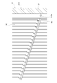
ところで、このようなシャッタ装置10では、複数のブレード30が閉状態であるとき、車両Cの走行風によりブレード30にラム圧が加わると、図5に二点鎖線で示されるようにブレード30が空気流れ方向Yに撓むように変形する可能性がある。また、ラム圧によりブレード30に加わる力がフレーム20に伝達されることにより、図6に二点鎖線で示されるようにフレーム20が空気流れ方向Yに撓むように変形する可能性もある。図5及び図6に示されるようにフレーム20及びブレード30が変形した場合、フレーム20からブレード30が滑落するおそれがある。また、図5及び図6に示されるようにフレーム20及びブレード30が変形した場合、シャッタ装置10に対して空気流れ方向Yの下流側に配置される熱交換器6にフレーム20やブレード30が接触し、フレーム20やブレード30、又は熱交換器6が損傷する可能性がある。
一方、熱交換器6及びシャッタ装置10は、車両Cの振動によりZ軸方向、すなわち車両Cの上下方向に振動する可能性がある。熱交換器6及びシャッタ装置10のそれぞれの形状や重量は異なるため、熱交換器6及びシャッタ装置10は異なる態様で振動する。そのため、熱交換器6及びシャッタ装置10の相対的な位置関係にずれが生じる。仮に熱交換器6がシャッタ装置10よりも大きい振幅で振動しているような場合、図7に示されるようにフレーム20が熱交換器6に接触した際に、フレーム20における熱交換器6との接触部分に大きな摩擦力が発生するため、この接触部分においてフレーム20、又は熱交換器6が寿命よりも早期に破損する可能性がある。
また、図8に示されるように、複数のブレード30が閉状態であるときに、隣り合うブレード30間の狭い隙間S10を空気が流れる。狭い隙間S10を空気が流れる際、その空気の流速が速くなることから、隙間S10に負圧が発生する。この負圧によりブレード30が空気流れ方向Yの下流側に変形すると、隙間S10に発生している負圧が小さくなるため、ブレード30が元の形状に復帰する。ブレード30が元の形状に復帰することにより、隙間S10に再び負圧が発生するため、ブレード30が変形する。このように、複数のブレード30の間の隙間S10に発生する負圧によりブレード30が変形を繰り返すことにより、ブレード30が自励振動する。このようなブレード30の自励振動は騒音の要因になる。また、ブレード30の自励振動がシャッタ装置10の他の部分に伝達されて他の部分が振動することにより、シャッタ装置10の各種部品の摩耗が助長される等の問題を招く可能性もある。
そこで、本実施形態のシャッタ装置10では、図5に示されるようなブレード30の変形や、図6及び図7に示されるフレーム20の変形を抑制するために、図2に示されるように、フレーム20にブラケット80及び棒状部材90が組み付けられている。また、棒状部材90は、図8に示されるようなブレード30の自励振動を抑制するための部材としても機能する。シャッタ装置10では、ブラケット80及び棒状部材90によりブレード30及びフレーム20の変形を抑制することで、フレーム20からブレード30の脱落が抑制されている。すなわち、本実施形態では、ブラケット80及び棒状部材90が、フレーム20に対するブレード30の支持を補助する補助部材に相当する。
次に、ブラケット80及び棒状部材90の構造の詳細について説明する。
図2に示されるように、ブラケット80は、右側フレーム片212の中央部と左右補強用フレーム片221の右端部との接続部分、左側フレーム片213の中央部と左右補強用フレーム片221の左端部との接続部分、並びに上下補強用フレーム片220の中央部と左右補強用フレーム片221の中央部との接続部分にそれぞれ設けられている。各部位に設けられるブラケット80の形状は同一であるため、以下では、上下補強用フレーム片220の中央部と左右補強用フレーム片221の中央部との接続部分に設けられるブラケット80の構造について代表して説明する。
図2に示されるように、ブラケット80は、右側フレーム片212の中央部と左右補強用フレーム片221の右端部との接続部分、左側フレーム片213の中央部と左右補強用フレーム片221の左端部との接続部分、並びに上下補強用フレーム片220の中央部と左右補強用フレーム片221の中央部との接続部分にそれぞれ設けられている。各部位に設けられるブラケット80の形状は同一であるため、以下では、上下補強用フレーム片220の中央部と左右補強用フレーム片221の中央部との接続部分に設けられるブラケット80の構造について代表して説明する。
図9に示されるように、このブラケット80は、上下補強用フレーム片220の中央部と左右補強用フレーム片221の中央部との接続部分、換言すれば補強用フレーム片22における十字の中央部分を補強している。ブラケット80は、樹脂材料により形成されている。
ブラケット80は、補強用フレーム片22において空気流れ方向Yの下流側に位置する外面に組み付けられている。ブラケット80は、板状に形成されるベース部81と、ベース部81の両側面のそれぞれからY軸方向に平行な方向に伸びるように形成される係合部82,83とを有している。
上下補強用フレーム片220において左右補強用フレーム片221との接続部分の上方の部位には、爪部223がX軸方向の両側面に形成されている。爪部223には、ブラケット80の係合部82がY軸方向において係合している。
図10に示されるように、Z軸方向におけるブラケット80の係合部82の孔の長さL1は、Z軸方向における爪部223の長さL2よりも長くなっている。これにより、ブラケット80の係合部82の上側内壁面と補強用フレーム片22の爪部223との間に隙間S20が形成されている。また、ブラケット80の係合部82の下側内壁面と補強用フレーム片22の爪部223との間にも隙間S21が形成されている。これらの隙間S20,S21により。ブラケット80は、補強用フレーム片22に対してZ軸方向に相対変位可能となっている。
図10に示されるように、Z軸方向におけるブラケット80の係合部82の孔の長さL1は、Z軸方向における爪部223の長さL2よりも長くなっている。これにより、ブラケット80の係合部82の上側内壁面と補強用フレーム片22の爪部223との間に隙間S20が形成されている。また、ブラケット80の係合部82の下側内壁面と補強用フレーム片22の爪部223との間にも隙間S21が形成されている。これらの隙間S20,S21により。ブラケット80は、補強用フレーム片22に対してZ軸方向に相対変位可能となっている。
図9に示されるように、上下補強用フレーム片220において左右補強用フレーム片221との接続部分の下方の部位には、ブラケット80の係合部83が係合する同様の爪部224がX軸方向の両側面に形成されている。
ブラケット80のベース部81は、リンク部材60の中央部に対向するように配置されている。これにより、ブラケット80は、リンク部材60の中央部分を左右補強用フレーム片221に対して保持している。
ブラケット80のベース部81は、リンク部材60の中央部に対向するように配置されている。これにより、ブラケット80は、リンク部材60の中央部分を左右補強用フレーム片221に対して保持している。
ところで、仮にフレーム20の変形により左右補強用フレーム片221からリンク部材60が滑落したような場合、左右補強用フレーム片221及びリンク部材60により支持されているブレード30が滑落するおそれがある。この点、本実施形態のシャッタ装置10では、図9に示されるように、ブラケット80が、左右補強用フレーム片221に対してリンク部材60を保持している。これにより、左右補強用フレーム片221からのリンク部材60の滑落を抑制することができるため、結果としてフレーム20からのブレード30の滑落を抑制することができる。このように、ブラケット80は、フレーム20からのブレード30の滑落を抑制する補助部材として機能している。
図9に示されるように、ブラケット80の表面には、ゴム等の弾性体84が一体的に成形されている。すなわち、ブラケット80は、樹脂材料とゴム等の弾性材料とにより成形される2色成形品からなる。
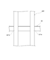
図2に示されるように、棒状部材90は、フレーム20の上方の領域に配置される複数のブレード30の中央部に対向する位置と、フレーム20の下方の領域に配置される複数のブレード30の中央部に対向する位置とにそれぞれに配置されている。図11に示されるように、棒状部材90の一端部は、右側フレーム片212に形成された挿入孔212aに挿入されて固定されている。棒状部材90の他端部は、同様に、左側フレーム片213に形成された挿入孔に挿入されて固定されている。図12に示されるように、棒状部材90の中央部は、左右補強用フレーム片221に形成された挿通孔221aに挿通されることにより、左右補強用フレーム片221により保持されている。
図2に示されるように、棒状部材90は、フレーム20の上方の領域に配置される複数のブレード30の中央部に対向する位置と、フレーム20の下方の領域に配置される複数のブレード30の中央部に対向する位置とにそれぞれに配置されている。図11に示されるように、棒状部材90の一端部は、右側フレーム片212に形成された挿入孔212aに挿入されて固定されている。棒状部材90の他端部は、同様に、左側フレーム片213に形成された挿入孔に挿入されて固定されている。図12に示されるように、棒状部材90の中央部は、左右補強用フレーム片221に形成された挿通孔221aに挿通されることにより、左右補強用フレーム片221により保持されている。
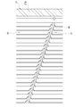
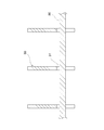
図11及び図13に示されるように、棒状部材90は、各ブレード30の切欠き部31に対向する位置に配置されている。図14及び図15に示されるように、各ブレード30が開状態になったとき、各ブレード30の切欠き部31に棒状部材90が挿入されるようになっている。
棒状部材90は、右側フレーム片212、左側フレーム片213、及び左右補強用フレーム片221に組み付けられることにより、空気流れ方向Yの下流側へのフレーム20の変形を抑制することにより、フレーム20からのブレード30の滑落を抑制する補助部材として機能している。
また、図11及び図13に示されるように各ブレード30が閉状態であるとき、各ブレード30がラム圧や自励振動等により空気流れ方向Yの下流側に変形したとき、各ブレード30が棒状部材90に接触する。これにより、各ブレード30のそれ以上の変形が棒状部材90により規制される。棒状部材90は、このようにして空気流れ方向Yの下流側へのブレード30の変形を更に抑制することにより、フレーム20からのブレード30の滑落を抑制する補助部材として機能している。
さらに、空気流れ方向Yの下流側へのブレード30の変形が棒状部材90により抑制されることで、各ブレード30が、空気流れ方向Yの下流側に配置される熱交換器6に接触することを回避できる。また、各ブレード30が棒状部材90に接触することにより各ブレード30の自励振動を抑制することができるため、各ブレード30の自励振動に起因して発生する騒音やシャッタ装置10の各種部品の摩耗等を抑制することができる。
また、ラム圧によりフレーム20が変形する場合、フレーム20において最も変形し易い部分はフレーム20の中央部分となる。仮にフレーム20の中央部分が空気流れ方向Yの下流側に大きく変形したような場合、フレーム20の中央部分に設けられるブラケット80が熱交換器6に接触することになる。その際、ブラケット80の表面に設けられる弾性体84が熱交換器6に接触するため、フレーム20が熱交換器6に接触した際にフレーム20に加わる衝撃力を弾性体84により吸収することができる。よって、フレーム20に加わる衝撃力を緩和することができる。
さらに、車両Cの振動に伴って熱交換器6に振動が発生している状況において、この振動している熱交換器6にブラケット80が接触した場合、ブラケット80の弾性体84と熱交換器6との間に発生する摩擦力により、ブラケット80が熱交換器6と一体となって車両Cの上下方向に、すなわちZ軸方向に変位する。この際、ブラケット80の係合部82とフレーム20の爪部223との間、並びにブラケット80の係合部83とフレーム20の爪部224との間には、Z軸方向に隙間が形成されているため、フレーム20に対してブラケット80が相対変位することが可能である。フレーム20に対してブラケット80が相対変位することにより、振動する熱交換器6とフレーム20との変位差をブラケット80により吸収することができるため、熱交換器6の接触部分においてフレーム20に過度の摩擦力が加わることを抑制できる。そのため、フレーム、又は熱交換器の早期の破損を防止することが可能である。
以上説明した本実施形態のシャッタ装置10によれば、以下の(1)~(12)に示される作用及び効果を得ることができる。
(1)ブラケット80及び棒状部材90は、フレーム20に組み付けられ、フレーム20に対するブレード30の支持を補助している。このような構成によれば、フレーム20からのブレード30の滑落を抑制することができる。
(2)ブラケット80は、左右補強用フレーム片221に対してリンク部材60を保持している。これにより、左右補強用フレーム片221からリンク部材60が滑落することに起因して発生するブレード30の滑落を抑制することができる。
(1)ブラケット80及び棒状部材90は、フレーム20に組み付けられ、フレーム20に対するブレード30の支持を補助している。このような構成によれば、フレーム20からのブレード30の滑落を抑制することができる。
(2)ブラケット80は、左右補強用フレーム片221に対してリンク部材60を保持している。これにより、左右補強用フレーム片221からリンク部材60が滑落することに起因して発生するブレード30の滑落を抑制することができる。
(3)ブラケット80は、空気流れ方向Yの下流側に位置するフレーム20の外面に組み付けられている。このような構成によれば、空気流れ方向Yの下流側へのフレーム20の変形をブラケット80により効果的に抑制することができる。
(4)ブラケット80の表面には、弾性体84が一体的に設けられている。これにより、フレーム20が熱交換器6に接触した際にフレーム20、又は熱交換器6に加わる衝撃力を弾性体84により吸収することができるため、フレーム20に加わる衝撃力を緩和することができる。
(4)ブラケット80の表面には、弾性体84が一体的に設けられている。これにより、フレーム20が熱交換器6に接触した際にフレーム20、又は熱交換器6に加わる衝撃力を弾性体84により吸収することができるため、フレーム20に加わる衝撃力を緩和することができる。
(5)ブラケット80の係合部82とフレーム20の爪部223との間、並びにブラケット80の係合部83とフレーム20の爪部224との間には、Z軸方向において、換言すれば空気流れ方向Yに直交する方向において隙間が形成されている。このような構成によれば、ブラケット80が熱交換器6に接触した際に、振動する熱交換器6とフレーム20との変位差をブラケット80により吸収することができるため、熱交換器6との接触部分においてフレーム20、又は熱交換器6に過度の摩擦力が加わることが抑制できる。
(6)シャッタ装置10には、複数のブラケット80及び複数の棒状部材90が設けられている。これにより、より確実にフレーム20に対してブレード30を支持することができる。
(7)左右補強用フレーム片221の右端部にそれぞれ配置されるブラケット80は、フレーム20に対してシャフト50を保持する機能を更に有している。このような構成によれば、フレーム20からのシャフト50の脱落をブラケット80により防止することができる。
(7)左右補強用フレーム片221の右端部にそれぞれ配置されるブラケット80は、フレーム20に対してシャフト50を保持する機能を更に有している。このような構成によれば、フレーム20からのシャフト50の脱落をブラケット80により防止することができる。
(8)棒状部材90は、空気流れ方向Yの下流側へのブレード30の変形を更に抑制している。このような構成によれば、シャッタ装置10に隣接する熱交換器6にブレード30が接触することを棒状部材90により防ぐことができる。また、ブレード30の自励振動を棒状部材90により抑制することができるため、自励振動に起因してブレード30に発生する騒音や部品の摩耗を抑制することができる。
(9)棒状部材90は、複数のブレード30に対して空気流れ方向Yの下流側に対向して配置され、且つX軸方向に伸びるように形成されており、フレーム20に組み付けられている。このような棒状部材90によれば、ブレード30の変形を抑制することの可能な部材を容易に実現することができる。
(10)ブレード30には、開状態であるときに棒状部材90との干渉を回避するための切欠き部31が形成されている。このような構成によれば、ブレード30に近接するように棒状部材90を配置することができるため、ブレード30の変形を棒状部材90により抑制し易くなる。
(11)棒状部材90は、複数のブレード30の長手方向の中央部に対向するように配置されている。このような構成によれば、ブレード30において最も変形し易い部分の変形を棒状部材90により抑制することができるため、ブレード30の変形を効果的に抑制することができる。
なお、上記実施形態は、以下の形態にて実施することもできる。
・図16に示されるように、ブラケット80は、空気流れ方向の下流側に位置するフレーム20の外面だけでなく、空気流れ方向の上流側に位置するフレーム20の外面に組み付けられていても良い。
・図16に示されるように、ブラケット80は、空気流れ方向の下流側に位置するフレーム20の外面だけでなく、空気流れ方向の上流側に位置するフレーム20の外面に組み付けられていても良い。
・棒状部材90は、複数のブレード30の長手方向の中央部以外の部分に対向するように配置されていてもよい。
・シャッタ装置10には、ブラケット80及び棒状部材90のいずれか一方のみが設けられていてもよい。
・シャッタ装置10には、ブラケット80及び棒状部材90のいずれか一方のみが設けられていてもよい。
・本開示は上記の具体例に限定されるものではない。上記の具体例に、当業者が適宜設計変更を加えたものも、本開示の特徴を備えている限り、本開示の範囲に包含される。前述した各具体例が備える各要素、及びその配置、条件、形状等は、例示したものに限定されるわけではなく適宜変更することができる。前述した各具体例が備える各要素は、技術的な矛盾が生じない限り、適宜組み合わせを変えることができる。
Claims (12)
- 枠状に形成され、車両(C)のグリル開口部(2)から導入された空気が枠内の空間を流れるフレーム(20)と、
前記フレームにより回転可能に支持され、前記フレームの枠内の空間を開閉する複数のブレード(30)と、
前記ブレードを開閉動作させるアクチュエータ装置(40)と、
前記フレームに組み付けられ、前記フレームに対する前記ブレードの支持を補助する補助部材(80,90)と、を備える
車両のシャッタ装置。 - 前記フレームに沿って配置されるシャフト(50)と、
前記フレームに沿って配置され、前記フレームと共に複数の前記ブレードを回転可能に支持するとともに、前記シャフトの回転力を複数の前記ブレードに伝達することにより複数の前記ブレードを開閉動作させるリンク部材(60)と、を更に備え、
前記アクチュエータ装置は、前記シャフトを回転させることにより、前記リンク部材を介して複数の前記ブレードを開閉動作させるものであって、
前記補助部材(80)は、前記フレームに対して前記リンク部材を保持することにより、前記フレームに対する前記ブレードの支持を補助している
請求項1に記載の車両のシャッタ装置。 - 前記補助部材は、前記空気流れ方向の下流側に位置する前記フレームの外面に組み付けられている
請求項1又は2に記載の車両のシャッタ装置。 - 前記補助部材の表面には、弾性体(84)が一体的に設けられている
請求項3に記載の車両のシャッタ装置。 - 前記補助部材は、前記フレームに形成された爪部(223,224)に対して前記空気流れ方向において係合する係合部(82,83)を有し、前記係合部が前記フレームの前記爪部に係合することにより前記フレームに対して組み付けられており、
前記補助部材の前記係合部と前記フレームの前記爪部との間には、前記空気流れ方向に直交する方向において隙間が形成されている
請求項4に記載の車両のシャッタ装置。 - 前記補助部材は、前記フレームに対して空気流れ方向の上流側に更に配置されている
請求項3~5のいずれか一項に記載の車両のシャッタ装置。 - 前記補助部材を複数備える
請求項1~6のいずれか一項に記載の車両のシャッタ装置。 - 前記補助部材(80)は、前記フレームに対して前記シャフトを更に保持している
請求項2に記載の車両のシャッタ装置。 - 前記補助部材(90)は、前記空気流れ方向の下流側への前記ブレードの変形を抑制することにより、前記フレームに対する前記ブレードの支持を補助している
請求項1に記載の車両のシャッタ装置。 - 複数の前記ブレードは、その長手方向に直交する方向である所定方向に並べて配置されており、
前記補助部材は、複数の前記ブレードに対して前記空気流れ方向の下流側に対向して配置され、且つ前記所定方向に伸びるように形成される棒状の部材からなり、前記フレームに組み付けられている
請求項9に記載の車両のシャッタ装置。 - 前記ブレードには、開状態であるときに前記補助部材との干渉を回避する切欠き部(31)が形成されている
請求項10に記載の車両のシャッタ装置。 - 前記補助部材は、複数の前記ブレードの長手方向の中央部に対向するように配置されている
請求項10又は11に記載の車両のシャッタ装置。
Priority Applications (1)
| Application Number | Priority Date | Filing Date | Title |
|---|---|---|---|
| US17/153,093 US11951824B2 (en) | 2018-07-26 | 2021-01-20 | Shutter device for vehicle |
Applications Claiming Priority (2)
| Application Number | Priority Date | Filing Date | Title |
|---|---|---|---|
| JP2018139903A JP7115104B2 (ja) | 2018-07-26 | 2018-07-26 | 車両のシャッタ装置 |
| JP2018-139903 | 2018-07-26 |
Related Child Applications (1)
| Application Number | Title | Priority Date | Filing Date |
|---|---|---|---|
| US17/153,093 Continuation US11951824B2 (en) | 2018-07-26 | 2021-01-20 | Shutter device for vehicle |
Publications (1)
| Publication Number | Publication Date |
|---|---|
| WO2020021963A1 true WO2020021963A1 (ja) | 2020-01-30 |
Family
ID=69181574
Family Applications (1)
| Application Number | Title | Priority Date | Filing Date |
|---|---|---|---|
| PCT/JP2019/025860 Ceased WO2020021963A1 (ja) | 2018-07-26 | 2019-06-28 | 車両のシャッタ装置 |
Country Status (3)
| Country | Link |
|---|---|
| US (1) | US11951824B2 (ja) |
| JP (1) | JP7115104B2 (ja) |
| WO (1) | WO2020021963A1 (ja) |
Cited By (2)
| Publication number | Priority date | Publication date | Assignee | Title |
|---|---|---|---|---|
| WO2021181849A1 (ja) * | 2020-03-13 | 2021-09-16 | 株式会社デンソー | 車両のシャッタ装置 |
| JP7447772B2 (ja) | 2020-03-13 | 2024-03-12 | 株式会社デンソー | 車両のシャッタ装置 |
Families Citing this family (3)
| Publication number | Priority date | Publication date | Assignee | Title |
|---|---|---|---|---|
| JP7388030B2 (ja) | 2019-07-26 | 2023-11-29 | 株式会社デンソー | 車両のシャッタ装置 |
| JP2021037877A (ja) * | 2019-09-04 | 2021-03-11 | 株式会社デンソー | シャッター装置 |
| JP7336338B2 (ja) * | 2019-09-27 | 2023-08-31 | 株式会社デンソー | 車両のシャッタ装置 |
Citations (5)
| Publication number | Priority date | Publication date | Assignee | Title |
|---|---|---|---|---|
| JP2015217827A (ja) * | 2014-05-19 | 2015-12-07 | シロキ工業株式会社 | 車両用シャッター装置 |
| JP2016147553A (ja) * | 2015-02-10 | 2016-08-18 | 本田技研工業株式会社 | 車両のシャッタ開閉機構 |
| JP2016205117A (ja) * | 2015-04-27 | 2016-12-08 | コベルコ建機株式会社 | 建設機械 |
| JP2017043174A (ja) * | 2015-08-25 | 2017-03-02 | アイシン精機株式会社 | グリルシャッタ装置 |
| JP2017185991A (ja) * | 2016-03-31 | 2017-10-12 | 株式会社デンソー | シャッター装置及びシャッター装置の製造方法 |
Family Cites Families (4)
| Publication number | Priority date | Publication date | Assignee | Title |
|---|---|---|---|---|
| FR2906759B1 (fr) * | 2006-10-09 | 2011-04-01 | Peugeot Citroen Automobiles Sa | Aerateur pour vehicule automobile |
| US9902256B2 (en) | 2014-05-19 | 2018-02-27 | Shiroki Corporation | Vehicular shutter device |
| JP2016055719A (ja) | 2014-09-08 | 2016-04-21 | カルソニックカンセイ株式会社 | グリルシャッター |
| JP2019100389A (ja) | 2017-11-29 | 2019-06-24 | 株式会社デンソー | 連結部材、構造体モジュール |
-
2018
- 2018-07-26 JP JP2018139903A patent/JP7115104B2/ja active Active
-
2019
- 2019-06-28 WO PCT/JP2019/025860 patent/WO2020021963A1/ja not_active Ceased
-
2021
- 2021-01-20 US US17/153,093 patent/US11951824B2/en active Active
Patent Citations (5)
| Publication number | Priority date | Publication date | Assignee | Title |
|---|---|---|---|---|
| JP2015217827A (ja) * | 2014-05-19 | 2015-12-07 | シロキ工業株式会社 | 車両用シャッター装置 |
| JP2016147553A (ja) * | 2015-02-10 | 2016-08-18 | 本田技研工業株式会社 | 車両のシャッタ開閉機構 |
| JP2016205117A (ja) * | 2015-04-27 | 2016-12-08 | コベルコ建機株式会社 | 建設機械 |
| JP2017043174A (ja) * | 2015-08-25 | 2017-03-02 | アイシン精機株式会社 | グリルシャッタ装置 |
| JP2017185991A (ja) * | 2016-03-31 | 2017-10-12 | 株式会社デンソー | シャッター装置及びシャッター装置の製造方法 |
Cited By (2)
| Publication number | Priority date | Publication date | Assignee | Title |
|---|---|---|---|---|
| WO2021181849A1 (ja) * | 2020-03-13 | 2021-09-16 | 株式会社デンソー | 車両のシャッタ装置 |
| JP7447772B2 (ja) | 2020-03-13 | 2024-03-12 | 株式会社デンソー | 車両のシャッタ装置 |
Also Published As
| Publication number | Publication date |
|---|---|
| US11951824B2 (en) | 2024-04-09 |
| JP7115104B2 (ja) | 2022-08-09 |
| US20210138892A1 (en) | 2021-05-13 |
| JP2020015426A (ja) | 2020-01-30 |
Similar Documents
| Publication | Publication Date | Title |
|---|---|---|
| WO2020021963A1 (ja) | 車両のシャッタ装置 | |
| US10245939B2 (en) | Grille shutter device | |
| KR101576970B1 (ko) | 쿨링모듈 | |
| JP2009162127A (ja) | 車両用送風装置 | |
| KR20120106046A (ko) | 액티브 에어 플랩 | |
| JP2025508975A (ja) | 自動車の前面モジュール用の空気流制御装置 | |
| WO2020045312A1 (en) | Cooling apparatus for vehicle | |
| KR101362332B1 (ko) | 프론트 엔드 모듈 | |
| WO2021019954A1 (ja) | シャッター装置 | |
| JPH08165928A (ja) | 熱交換器用ファンシュラウド | |
| US10816281B2 (en) | Cooling module supporting structure | |
| KR20150062322A (ko) | 차량의 액티브 에어 플랩 | |
| JP7567283B2 (ja) | 車両のシャッタ装置 | |
| JP7358820B2 (ja) | 車両のシャッタ装置 | |
| JP7336338B2 (ja) | 車両のシャッタ装置 | |
| WO2021020108A1 (ja) | 車両のシャッタ装置 | |
| JP7447772B2 (ja) | 車両のシャッタ装置 | |
| KR102145514B1 (ko) | 쿨링모듈 장착구조 | |
| CN223173915U (zh) | 减振支架及汽车 | |
| CN223014923U (zh) | 散热系统和无人机 | |
| KR102082260B1 (ko) | 팬 및 쉬라우드 조립체 | |
| KR20150070770A (ko) | 액티브 에어 플랩 | |
| KR20110048273A (ko) | 차량 쿨링팬 구동용 풀리 어셈블리 | |
| JP3336915B2 (ja) | 空調用コンデンサ、空調用コンデンサの支持構造および車両用冷却装置 | |
| KR101566723B1 (ko) | 차량용 냉각팬 쉬라우드 |
Legal Events
| Date | Code | Title | Description |
|---|---|---|---|
| 121 | Ep: the epo has been informed by wipo that ep was designated in this application |
Ref document number: 19841137 Country of ref document: EP Kind code of ref document: A1 |
|
| NENP | Non-entry into the national phase |
Ref country code: DE |
|
| 122 | Ep: pct application non-entry in european phase |
Ref document number: 19841137 Country of ref document: EP Kind code of ref document: A1 |