WO2020009171A1 - 熱間プレス成形品の製造方法、プレス成形品、ダイ金型、及び金型セット - Google Patents
熱間プレス成形品の製造方法、プレス成形品、ダイ金型、及び金型セット Download PDFInfo
- Publication number
- WO2020009171A1 WO2020009171A1 PCT/JP2019/026536 JP2019026536W WO2020009171A1 WO 2020009171 A1 WO2020009171 A1 WO 2020009171A1 JP 2019026536 W JP2019026536 W JP 2019026536W WO 2020009171 A1 WO2020009171 A1 WO 2020009171A1
- Authority
- WO
- WIPO (PCT)
- Prior art keywords
- die
- layer
- steel sheet
- press
- mold
- Prior art date
Links
Images


Classifications
-
- B—PERFORMING OPERATIONS; TRANSPORTING
- B21—MECHANICAL METAL-WORKING WITHOUT ESSENTIALLY REMOVING MATERIAL; PUNCHING METAL
- B21D—WORKING OR PROCESSING OF SHEET METAL OR METAL TUBES, RODS OR PROFILES WITHOUT ESSENTIALLY REMOVING MATERIAL; PUNCHING METAL
- B21D22/00—Shaping without cutting, by stamping, spinning, or deep-drawing
- B21D22/20—Deep-drawing
- B21D22/26—Deep-drawing for making peculiarly, e.g. irregularly, shaped articles
-
- B—PERFORMING OPERATIONS; TRANSPORTING
- B21—MECHANICAL METAL-WORKING WITHOUT ESSENTIALLY REMOVING MATERIAL; PUNCHING METAL
- B21D—WORKING OR PROCESSING OF SHEET METAL OR METAL TUBES, RODS OR PROFILES WITHOUT ESSENTIALLY REMOVING MATERIAL; PUNCHING METAL
- B21D37/00—Tools as parts of machines covered by this subclass
- B21D37/10—Die sets; Pillar guides
-
- B—PERFORMING OPERATIONS; TRANSPORTING
- B21—MECHANICAL METAL-WORKING WITHOUT ESSENTIALLY REMOVING MATERIAL; PUNCHING METAL
- B21D—WORKING OR PROCESSING OF SHEET METAL OR METAL TUBES, RODS OR PROFILES WITHOUT ESSENTIALLY REMOVING MATERIAL; PUNCHING METAL
- B21D22/00—Shaping without cutting, by stamping, spinning, or deep-drawing
- B21D22/20—Deep-drawing
- B21D22/208—Deep-drawing by heating the blank or deep-drawing associated with heat treatment
-
- B—PERFORMING OPERATIONS; TRANSPORTING
- B21—MECHANICAL METAL-WORKING WITHOUT ESSENTIALLY REMOVING MATERIAL; PUNCHING METAL
- B21D—WORKING OR PROCESSING OF SHEET METAL OR METAL TUBES, RODS OR PROFILES WITHOUT ESSENTIALLY REMOVING MATERIAL; PUNCHING METAL
- B21D24/00—Special deep-drawing arrangements in, or in connection with, presses
- B21D24/04—Blank holders; Mounting means therefor
-
- B—PERFORMING OPERATIONS; TRANSPORTING
- B21—MECHANICAL METAL-WORKING WITHOUT ESSENTIALLY REMOVING MATERIAL; PUNCHING METAL
- B21D—WORKING OR PROCESSING OF SHEET METAL OR METAL TUBES, RODS OR PROFILES WITHOUT ESSENTIALLY REMOVING MATERIAL; PUNCHING METAL
- B21D37/00—Tools as parts of machines covered by this subclass
- B21D37/01—Selection of materials
Definitions
- the present disclosure relates to a method for manufacturing a hot press-formed product, a press-formed product, a die, and a die set.
- Most of the vehicle body structure is made of iron, especially steel plate. It is required to reduce the weight of the vehicle body while maintaining the strength of the structural material made of the steel sheet.
- the demand for such steel sheets is made not only in the automobile manufacturing industry but also in various manufacturing industries. Therefore, by increasing the mechanical strength of the steel sheet, it is possible to maintain or increase the mechanical strength of the structural material even when the steel sheet is thinner than conventionally used steel sheets.
- a material having high mechanical strength tends to have a reduced shape freezing property in a forming process such as a bending process. That is, when processing into a complicated shape, the processing itself becomes difficult.
- hot press forming hot press method, high temperature press method, die quench method
- a steel sheet to be formed is once heated to a high temperature, pressed and formed on a steel sheet softened by heating, and then cooled.
- the hot press forming since the steel sheet is once heated to a high temperature and softened, the steel sheet can be easily pressed. Furthermore, the mechanical strength of the steel sheet can be increased by the quenching effect of cooling after forming. Therefore, by this hot press molding, a molded product having both good shape freezing property and high mechanical strength can be obtained.
- Patent Literature 1 discloses a zinc oxide film (hereinafter also referred to as a “ZnO film”) or the like for the purpose of improving chemical conversion treatment and corrosion resistance in addition to hot lubrication to prevent generation of processing flaws.
- ZnO film a zinc oxide film
- a method for forming a film of a wurtzite compound on the surface of an Al-plated steel sheet is disclosed.
- Patent Literature 2 discloses a coating of one or more Zn compounds selected from the group consisting of Zn hydroxide, Zn phosphate, and organic acid Zn in order to enhance the adhesion of the ZnO coating during press molding. Is formed on the surface of an Al-plated steel sheet.
- a ZnO film is generated by heat when hot-press-forming an Al-plated steel sheet on which a Zn compound film is formed, a ZnO film having excellent adhesion is formed, and hot lubrication is performed. Properties, film adhesion, spot weldability, and corrosion resistance after painting can be improved.
- Patent Document 3 discloses a coating mold having a hard coating on the surface, wherein the hard coating includes an A layer made of a nitride having a thickness of 5 ⁇ m or more and a B layer made of a diamond-like carbon film.
- the layer B is on the outer surface side of the layer A, and the surface of the layer B satisfies an arithmetic average roughness Ra ⁇ 0.2 ⁇ m, a maximum height Rz ⁇ 2.0 ⁇ m, and a skewness Rsk ⁇ 0.
- a mold is disclosed.
- Patent Document 1 International Publication No. WO 2009/131233
- Patent Document 2 Japanese Patent Application Publication No. 2014-139350
- Patent Document 3 International Publication No. WO 2016/171273
- the plated steel sheets of Patent Documents 1 and 2 are all excellent in hot lubricity and can suppress generation of processing flaws.
- a slide of a hot press forming die on which the plated steel sheet slides such as a portion that becomes a vertical wall portion and a flange portion of the pressed product. Wear occurs on the moving surface. For this reason, in the high surface pressure portion of the hot press molding, mold care is required to cope with abrasion occurring on the sliding surface of the mold.
- An object of the present disclosure is to reduce wear of a sliding surface of a die when hot press-forming a plated steel sheet having at least one plating layer selected from the group consisting of a hot-dip galvanized layer and a zinc-nickel plated layer.
- An object of the present invention is to provide a method for producing a hot press-formed product, which suppresses generation. Further, the problem of the present disclosure is to provide a die set that suppresses the occurrence of wear on the sliding surface, a die set of a die die and a punch die, and a die set of a die die and a steel plate holding die. To provide.
- Another object of the present disclosure is to provide a press-formed product having excellent surface quality and suppressing occurrence of delayed fracture.
- the gist of the present disclosure is as follows. ⁇ 1> A method for producing a hot press-formed product, Placing a plated steel sheet having at least one type of plating layer selected from the group consisting of a hot-dip galvanized layer and a zinc-nickel plated layer on the die mold by closing a die hole of the die, and the plated steel sheet Hot press forming using the die mold, Has, The die mold is provided on the outer surface of the die hole and in a steel sheet contact surface that comes into contact with the plated steel sheet before being subjected to the hot press forming.
- the hard layer is a layer including a nitride layer and a hard coating layer on a surface of the nitride layer.
- ⁇ 4> The method for producing a hot press-formed product according to any one of ⁇ 1> to ⁇ 3>, wherein the plated steel sheet has a zinc compound layer or a metal zinc layer as an outermost layer on the plated layer.
- a steel sheet press-formed product The steel sheet has a steel base material having a hardness Hv_Parts of HV400 or more, at least one plating layer selected from the group consisting of a hot-dip galvanized layer and a zinc nickel plated layer on the steel base material, and A zinc oxide layer as the outermost layer,
- the press-formed product has a top plate, a vertical wall connected to the top plate via a first ridge, and a flange connected to the vertical wall via a second ridge.
- the radius of curvature [R min ] at a point where the radius of curvature is minimum in the second ridgeline portion is 3 mm or more and less than 10 mm
- SaB2] is 0.35 ⁇ m or more;
- the difference [StrB1-StrB2] between the aspect ratio [StrB1] of the surface texture at the location PB1 min on the top plate portion and the aspect ratio [StrB2] of the surface texture at the location PB2 min on the vertical wall portion is obtained.
- ⁇ 7> Used for hot press forming of a plated steel sheet having at least one type of plating layer selected from the group consisting of a galvanized layer and a zinc nickel plating layer,
- the skewness (Rsk) measured in the direction from the outside to the inside of the die hole is ⁇ 5 in the entire region adjacent to the die shoulder in the outer surface of the die hole and the surface adjacent to the die shoulder adjacent to the die shoulder.
- ⁇ 8> The die according to ⁇ 7>, wherein the hard layer is a layer having a nitride layer as an outermost layer.
- the hard layer is a layer including a nitride layer and a hard coating layer on a surface of the nitride layer.
- ⁇ 10> Used for hot press forming of a plated steel sheet having at least one type of plating layer selected from the group consisting of a galvanized layer and a zinc nickel plating layer, A die mold according to any one of ⁇ 7> to ⁇ 9>, and a punch mold, The punch die is directed inward from the outside of the punch portion to an entire region of the opposing surface opposing the die shoulder adjacent surface of the die die, where the die die opposes the portion having the hard layer.
- the second hard layer is a layer having a second nitride layer as an outermost layer.
- the second hard layer is a layer including a second nitride layer and a second hard coating layer on a surface of the second nitride layer.
- ⁇ 13> Used for hot press forming of a plated steel sheet having at least one type of plating layer selected from the group consisting of a galvanized layer and a zinc nickel plating layer, A die including the die according to any one of ⁇ 7> to ⁇ 9> and a steel plate holding die, The steel plate holding mold is provided such that the entire surface of the die surface facing the die shoulder adjacent surface of the die die facing the portion where the die die has the hard layer is provided from the outside to the inside of the punch insertion portion.
- the wear of the sliding surface of the die mold is reduced. It is possible to provide a method for producing a hot press-formed product that suppresses generation. Further, according to the present disclosure, a die, a die set of a die die and a punch die, and a die set of a die die and a steel plate holding die, which suppress the occurrence of wear of a sliding surface. Can be provided. Further, according to the present disclosure, it is possible to provide a press-formed product having excellent surface quality and suppressing occurrence of delayed fracture.
- FIG. 2 is a schematic view (perspective view) showing an example of a press-formed product obtained by hot press forming shown in FIG. 1.
- FIG. 2 is a schematic view (side view) showing an example of a press-formed product obtained by the hot press forming shown in FIG. 1.
- FIG. 4A It is a schematic diagram which shows another example of the press-formed product obtained by the hot press-forming concerning this embodiment. It is a schematic diagram which shows an example of the plating steel plate hot-press-molded by a die die and a punch die. It is an outline sectional view showing an example of the plating steel plate used for this embodiment. It is a schematic block diagram which shows the evaluation apparatus of hot lubricity.
- the “longitudinal direction of the press-formed product” is defined as the x direction.
- the x direction is a direction along a line connecting the centers of gravity of the ends in the longitudinal direction of the top plate.
- the “direction perpendicular to the longitudinal direction of the press-formed product and parallel to the top plate” is defined as the y direction.
- the y direction is a direction along a line connecting the first ridge lines in a cross section of the press-formed product orthogonal to the longitudinal direction.
- a method for manufacturing a hot press-formed product according to an embodiment of the present disclosure will be described.
- the manufacturing method of the hot press molded product according to the present embodiment A plated steel sheet having at least one type of plating layer selected from the group consisting of a hot-dip galvanized (hereinafter, also simply referred to as “GI plating”) layer and a zinc-nickel plating (hereinafter, also simply referred to as “Zn—Ni plating”) layer is formed by a die. Closing the die hole of the die and disposing it on the die, and hot-press-forming the plated steel sheet using the die.
- GI plating hot-dip galvanized
- Zn—Ni plating zinc-nickel plating
- the plated steel sheet may have only the GI plating layer as the plating layer, may have only the Zn—Ni plating layer, and may have the GI plating layer and the Zn—Ni plating layer. It may be an embodiment having both.
- the die mold is provided on the entire surface adjacent to the die shoulder portion of the steel plate contact surface that is in contact with the specific plated steel plate before hot press forming on the outer surface of the die hole.
- the hard layer has a skewness (Rsk) measured in a direction from the outside to the inside of the hole of ⁇ 5.0 to 1.2 and a hardness Hv_Die of HV1000 to 1550.
- the plated steel sheet When the plated steel sheet is placed on the die with the die hole of the die closed, the plated steel sheet may cover the whole or part of the die hole.
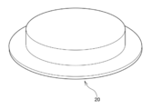
- the plated steel sheet when forming the cup-shaped hat material shown in FIG. 5, the plated steel sheet is arranged so as to cover all the die holes.
- the plated steel sheet When forming the grooved hat material of FIG. 2, the plated steel sheet is arranged so as to partially close the die hole. That is, the end of the plated steel sheet is disposed across the die hole.
- the method for manufacturing a hot press-formed product according to the present embodiment suppresses the occurrence of abrasion on the sliding surface of the die in the high surface pressure portion during the hot press forming, by the above-described configuration. And the manufacturing method of the hot press molded article concerning this embodiment was discovered by the knowledge shown below.
- a specific plated steel sheet (a plated steel sheet in which at least one of a GI plating layer and a Zn—Ni plating layer is provided on both surfaces of a steel sheet) of the related art for hot press forming is hot press-formed
- the GI plating layer or the Zn -Seizure occurs in which the zinc of the Ni plating layer reacts with the material (iron) of the die.
- Intermetallic compounds (zinc deposits) generated by this seizure sometimes adhered in large quantities to the surface of the die.
- Patent Documents 1 and 2 disclose a plated steel sheet having a ZnO film formed on the surface of a plating layer provided on both sides of a steel sheet (hereinafter referred to as a “plated steel sheet with a ZnO film”) for the purpose of suppressing the adhesion of the adhered matter to the die. ”) Has been proposed. Since the surface of the plated layer of the plated steel sheet with the ZnO film is covered with the ZnO film, even when hot press-forming, the adhesion of the adhered matter to the surface of the die mold due to seizure is suppressed. As a result, the coefficient of friction with the surface of the die is reduced.
- the mold wears even with the ZnO film.
- a high surface pressure is applied to a region adjacent to the die shoulder on the surface that slides on the plated steel sheet during hot press forming. Therefore, when the specific plated steel sheet is used irrespective of the presence or absence of the ZnO film, abrasion may occur on the sliding surface of the die.
- the outer surface of the die hole of the die, and the steel plate contact surface in contact with the specific plated steel plate before hot press forming is adjacent to the die shoulder. It has a hard layer in all areas.
- the skewness (Rsk) of the hard layer measured from the outside to the inside of the die hole is ⁇ 5.0 or more and 1.2 or less.
- the skewness Rsk is an index defined in JIS B 0601 (2001) and represents the symmetry of the peak and the valley with respect to the average line. When this Rsk is positive (0 ⁇ Rsk), it indicates a state where the peaks and valleys are unevenly distributed below the average line.
- the hard layer has a hardness Hv_Die of HV1000 or more and 1550 or less.
- the method for manufacturing a hot press-formed product according to the present embodiment is a method for manufacturing a hot press-formed product in which a plated steel sheet is heated, then pressed by a die, and hot press-formed. Then, in hot press forming, a plated steel sheet heated to a high temperature is press-formed by a mold. Thereafter, by cooling, a press-formed product having a desired shape is obtained. The hot press forming is performed after the plated steel sheet is placed on the die with the die hole closed.
- -Hot press molding- In press forming a steel sheet is drawn into a die hole of a die and formed.
- the edge of the die hole (die shoulder) is curved to protrude toward the outside of the die hole, the steel plate shrinks and deforms as it is drawn into the die hole.
- the thickness of the steel sheet increases as it approaches the edge of the die hole (die shoulder).
- a high surface pressure is applied to the steel sheet.
- wrinkles occur in the steel sheet as the steel sheet approaches the edge of the die hole (die shoulder).
- the die according to the present embodiment includes a hard layer at a position where a high surface pressure occurs.
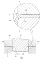
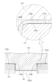
- FIG. 1 shows a die die, a holder (a steel plate holding die), and a plated steel plate that is hot press-formed by a punch.
- 2A and 2B show a hot press-formed product formed by the die of FIG.
- FIG. 1 is a cross-sectional view corresponding to a cross section in the y direction when the hot press-formed product 30 shown in FIG. 2A is formed by a die.
- the longitudinal direction of the hot press-formed product 30 is defined as an x direction
- a direction observed from the vertical wall portion 33 side in a direction orthogonal to the x direction is defined as a y direction.
- a direction perpendicular to the direction and observed from the top 31 is defined as a z-direction.
- the hot press-formed product 30 shown in FIGS. 2A and 2B includes two vertical wall portions 33, a top plate portion 31 connecting the two vertical wall portions 33 via the first ridge line portion 32, and two vertical wall portions. And a flange portion 35 connected to the opposite side of the top plate portion 31 via the second ridgeline portion 34 with respect to the flange 33.
- the shape has a portion PB0 min where the radius of curvature is minimum.
- the flange portion 35 has a curved portion in the longitudinal direction (x direction), and the radius of curvature of the entire flange portion 35 is not constant. Further, similarly to the flange portion 35, the top plate portion 31 also has a curved portion in the longitudinal direction (x direction).
- the hot press-formed product formed by the die according to the present embodiment is not limited to the shape shown in FIGS. 2A and 2B.
- a molded product having a flat top plate and a flat flange may be used.
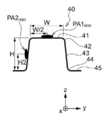
- FIG. 3B is a sectional view taken along the line AA ′ in FIG. 3A. 3A and 3B, the longitudinal direction of the hot press-formed product 40 is defined as the x direction, and the direction observed from the vertical wall portion 43 side among the directions orthogonal to the x direction is defined as the y direction, and is orthogonal to the x direction and the y direction. And the direction of observation from the top plate 41 side is the z direction.
- the hot press-formed product 40 shown in FIGS. 3A and 3B includes two vertical wall portions 43, a top plate portion 41 connecting the two vertical wall portions 43 via the first ridge line portion 42, and two vertical wall portions. And a flange 45 connected to the top 43 at a side opposite to the top plate 41 via the second ridge 44.
- a cross section cross section, for example, the cross section shown in FIG. 3B
- the cross section cut is observed, also has a shape in which the radius of curvature of the second ridgeline portion 44 has the same value.
- the shape is symmetrical.
- the hot press-formed product formed by the die according to the present embodiment is not limited to a symmetrical shape in a cross section as shown in FIGS. 3A and 3B.
- a molded product having different shapes on the left and right in a cross-sectional view may be used.
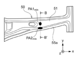
- FIG. 4B is a sectional view taken along the line BB ′ in FIG. 4A. 4A and 4B, the longitudinal direction of the hot press-formed product 50 is defined as the x direction, and among the directions orthogonal to the x direction, the direction observed from the side of the vertical wall 53a is defined as the y direction, and is orthogonal to the x direction and the y direction.
- the hot press-formed product 50 shown in FIGS. 4A and 4B has a top plate portion 51 connecting two vertical wall portions 53a, 53b and two vertical wall portions 53a, 53b via first ridge portions 52a, 52b, respectively. And flange portions 55a and 55b which are connected to the two vertical wall portions 53a and 53b via the second ridge portions 54a and 54b on the side opposite to the top plate portion 51, respectively.
- a cross section cross section in a direction orthogonal to the longitudinal direction (x direction) is observed, there are portions where the left and right shapes are not symmetric. For example, in the cross section shown in FIG.
- the heights in the z direction of the two first ridge lines 52 a and 52 b present on both sides of the flat top plate 51 are different, and the first ridge 52 a on the right is on the left. This is a shape that is higher than the first ridge line portion 52b in the z direction.
- the height of the two flange portions 55a and 55b in the z direction is also different, and the right flange portion 55a has a higher shape than the left flange portion 55b.
- the hot press-formed product 50 has a shape in which the radii of curvature of the second ridges 54a and 54b are different depending on the position to be cut when the cross section is observed, and the second ridges in the cross section shown in FIG. 4B.
- 54a has a shape with a minimum radius of curvature.
- hot press-formed products for example, hot press-formed products 30
- a punch 13 is pressed against a plated steel plate 10 and inserted into a die hole 11D. Then, the plated steel sheet 10 flows into the die hole 11D. At this time, as the plated steel plate 10 approaches the die hole 11D, the flange is shrunk and deformed to increase the thickness of the hot press-formed product 20.
- FIG. 1 In FIG. 1, during hot press-forming, a punch 13 is pressed against a plated steel plate 10 and inserted into a die hole 11D. Then, the plated steel sheet 10 flows into the die hole 11D. At this time, as the plated steel plate 10 approaches the die hole 11D, the flange is shrunk and deformed to increase the thickness of the hot press-formed product 20.
- a die mold (die) 11 is provided on a die shoulder 11 ⁇ / b> B of a steel plate contact surface 11 ⁇ / b> A which is on the outer surface of a die hole 11 ⁇ / b> D and is in contact with a plated steel plate 10 before hot press forming.
- the hard layer 11C is provided in all adjacent regions. When the hard layer 11C satisfies the skewness (Rsk) and the hardness Hv_Die, abrasion occurs on the sliding surface of the die 11 at a high surface pressure portion when a specific plated steel sheet is hot pressed. Is suppressed.
- the holder (steel plate holding die) 12 is provided with a second hard metal in an entire area of the opposing surface of the die 11 that faces the steel contact surface 11A, where the die 11 has the hard layer 11C. It is desirable to have layer 12C.
- the second hard layer 12C satisfies the skewness (Rsk) and the hardness Hv_Die, abrasion occurs on the sliding surface of the holder 12 at the high surface pressure portion when hot pressing the specific plated steel sheet. Is suppressed.
- the hard layer 11 ⁇ / b> C is preferably formed over the entire area along the die shoulder 11 ⁇ / b> B.
- a portion where a particularly high surface pressure occurs may be selected to form the hard layer 11C.
- the second hard layer 12C is formed over the entire area along a location facing the die shoulder 11B of the die mold 11.
- a portion where a particularly high surface pressure occurs may be selected to form the second hard layer 12C.
- the shape of the hot press-formed product to be formed is not limited to the shapes shown in FIGS. 2A and 2B, 3A and 3B, 4A and 4B, and the like.
- a press-formed product having various other shapes such as a hat-shaped press-formed product shown in FIG. 5 can be manufactured.
- the entire area adjacent to the die shoulder portion of the steel plate contact surface which is in contact with the specific plated steel sheet before hot press forming on the outer surface of the die hole as a die for use in the press forming, the entire area adjacent to the die shoulder portion of the steel plate contact surface which is in contact with the specific plated steel sheet before hot press forming on the outer surface of the die hole.
- the die in the high surface pressure portion is formed. The occurrence of wear on the sliding surface is suppressed.
- the hot press forming method in the hot press forming, for example, after blanking (punching) as necessary, the coated steel sheet is softened by heating to a high temperature. Then, the softened plated steel sheet is pressed and formed using a mold, and then cooled. Thus, in the hot press forming, the subsequent pressing can be easily performed by softening the plated steel sheet once.
- the hot-pressed press-formed product is quenched by heating and cooling, and becomes a high tensile strength molded product of about 1500 MPa or more.
- a heating method for hot press molding in addition to a normal electric furnace and a radiant tube furnace, a heating method using infrared heating, electric heating, induction heating, or the like can be used. Heating is performed in an oxidizing atmosphere.
- the die according to the present embodiment is used for hot press forming of a specific plated steel sheet having at least one of a GI plating layer and a Zn—Ni plating layer.
- a die for hot press forming a GI plated steel sheet having a GI plated layer as the outermost layer, or a GI plated steel sheet having a zinc compound layer or a metal zinc layer as the outermost layer on the GI plated layer Hot press forming is performed on a Zn-Ni plated steel sheet having a Zn-Ni plated layer as the outermost layer or a Zn-Ni plated steel sheet having a zinc compound layer or a metallic zinc layer as the outermost layer on the Zn-Ni plated layer.
- the skewness (Rsk) measured in the direction from the outside to the inside of the die hole in all the regions adjacent to the die shoulder in the surface outside the die hole and the surface adjacent to the die shoulder adjacent to the die shoulder.
- a hard layer having a hardness of not less than ⁇ 5.0 and not more than 1.2 and not less than ⁇ 5.0 and a hardness Hv_Die of not less than HV1000 and not more than 1550.
- a steel plate that is on the outer surface of the die hole and contacts a specific plated steel plate before hot-press forming.
- the skewness (Rsk) measured from the outside to the inside of the die hole in the direction from the outside to the inside of the die hole, and the hardness Hv_Die is HV1000 to 1550 in the entire area of the contact surface adjacent to the die shoulder. It has the following hard layer.
- the skewness (Rsk) of the hard layer is more preferably 1.0 or less, and further preferably 0.8 or less.
- the lower limit of the skewness (Rsk) of the hard layer is -5.0 or more, more preferably -3, from the viewpoint of suppressing an increase in manufacturing cost due to surface control for reducing the skewness (Rsk). 0.0 or more.
- the skewness Rsk is measured according to JIS B 0601 (2001). Specifically, the skewness Rsk is measured under the following measurement conditions in accordance with JIS B 0601 (2001).
- Measurement condition Measuring device: Mitutoyo Co., Ltd. “Surface roughness / contour shape measuring instrument Form Tracer” Measurement length L: 9.6 mm Cutoff wavelength ⁇ c: 0.8 mm Stylus tip shape: Tip angle 60 ° cone Stylus tip radius: 2 ⁇ m Measuring speed: 1mm / sec
- the method of controlling the skewness (Rsk) measured from the outside to the inside of the die hole in the hard layer to the above range is not particularly limited.
- the surface of the formed hard layer is polished, and at the time of this polishing, polishing is performed in a direction from the outside to the inside of the die hole (that is, a direction in which the plated steel plate slides during hot press forming).
- the polishing is performed by sliding the polishing sheet, there is a method in which the direction in which the polishing sheet is slid is a direction from the outside to the inside of the die hole.
- Hardness Hv_Die When the hardness Hv_Die of the hard layer included in the die is not less than HV1000, the occurrence of wear on the sliding surface of the die in the high surface pressure part during hot press forming is suppressed.
- the hardness Hv_Die of the hard layer is more preferably HV1200 or more.
- the upper limit of the hardness Hv_Die of the hard layer is HV1550 or less. By being HV 1550 or less, scraping of the GI plating layer or the Zn—Ni plating layer in the specific plated steel sheet, and in the case of having a zinc compound layer or a metal zinc layer, further suppressing the scraping of the zinc compound layer or the metal zinc layer. You.
- the hardness Hv_Die refers to a Vickers hardness specified by JIS-Z-2244 (2009), and in this specification, a hardness value under a test load of 0.2452 N in a Vickers hardness test method. is there. HM-115 manufactured by Mitutoyo Corporation is used for the micro Vickers tester.
- the material and the forming method of the hard layer formed on the die are not limited as long as they satisfy the skewness Rsk and the hardness Hv_Die described above.
- the hard layer include a layer having a nitride layer as the outermost layer.
- a layer having a hard coating layer (more preferably, a laminated hard layer including a nitride layer and a hard coating layer on the surface of the nitride layer) may be mentioned.
- the formation of the nitrided layer is preferably performed by a surface hardening treatment using diffusion, for example, a nitridation treatment.
- the formation of the nitrided layer is performed, for example, by subjecting the base material of the die to ion nitriding, that is, performing ion nitriding by adjusting the temperature in an atmosphere of a predetermined concentration of N 2 and H 2 gas.
- a compound layer called a nitride layer called a white layer formed by the nitriding treatment causes a decrease in adhesiveness
- the compound layer is prevented from being formed by controlling the processing conditions, or is removed by polishing or the like. It is desirable to do.
- the hard coating layer examples include a deposited film formed by physical vapor deposition (PVD).
- PVD physical vapor deposition
- CVD chemical vapor deposition
- the physical vapor deposition method for example, an arc ion plating method and a sputtering method are desirable.
- a film containing at least one of Ti and Cr is preferably used as the deposited film as the hard coating layer.
- the metal element portion is any one of a nitride, a carbide, and a carbonitride mainly composed of one or more selected from Ti, Cr, and Al. Further, it is more preferable that the metal element portion is any of a nitride, a carbide and a carbonitride mainly composed of Ti or Cr.
- the ratio of Ti, Cr or Al (or Ti or Cr) is 70 (at.%) Or more in the ratio of only the metal (including semimetal) composition part, excluding nitrogen and carbon. Further, the content is preferably 90 (at.%) Or more (including substantially 100 (at.%)).
- the deposited film as the hard coating layer is formed by, for example, adjusting the temperature and gas pressure using various metal targets and reaction gases (N 2 gas, CH 4 gas, etc.), which are evaporation sources of metal components, and adjusting the Bias voltage.
- a PVD film can be formed on the surface of the base material of the die.
- Specific examples include a nitride film, a carbide film, a carbonitride film, and a diamond-like carbon (DLC) film mainly composed of one or more selected from Ti, Cr and Al.
- a laminated hard layer including a nitrided layer and a hard coating layer on the surface of the nitrided layer is formed, for example, by forming a nitrided layer by the above-mentioned method, and then further by a hard coating layer (for example, a vapor-deposited film) by the above-described method. Is obtained.
- the metal material of the base material of the die is not particularly specified, and known metal materials such as cold die steel, hot die steel, high-speed steel, and cemented carbide can be used.
- improved metal types that have been proposed as steel types that can be used in conventional dies including standard metal types (steel types) according to JIS and the like, can also be applied.
- a mold set is a combination of a die mold and a punch mold having a convex portion corresponding to a die hole of the die mold and a facing surface facing a steel plate contact surface (adjacent surface of the die) of the die mold. It is. Also, the mold set is a steel plate holding mold having a die mold and a facing surface facing a steel plate contact surface (a surface adjacent to a die shoulder) of the die mold and having a hole through which a punch inserted into the die hole passes. (Holder) combinations are also included.
- the first mold set according to the present embodiment includes the die mold and the punch mold according to the above-described embodiment.
- the punch die is directed from the outside of the punch portion to the inside of the entire surface of the opposing surface opposing the die shoulder adjacent surface (the steel plate contact surface) of the die die, where the die die has a hard layer.
- the second hard layer has a skewness (Rsk) measured in the direction of ⁇ 5.0 or more and 1.2 or less and a hardness Hv_Die of HV1000 or more and 1550 or less.
- the die mold (die) 111 shown in FIG. 6 has a die shoulder portion of a steel plate contact surface 111A that is the outer surface of the die hole 111D and contacts the plated steel plate 10 before hot press forming.
- a hard layer 111C is provided in the entire region adjacent to 111B.
- the punch (punch die) 113 is provided with a second hard layer on the entire area of the opposing surface of the die 111 that faces the steel plate contact surface 111A, where the die 111 has a hard layer 111C. It is desirable to have 113C. This is because the wrinkled plated steel sheet 10 comes into contact with a certain portion of the second hard layer 113C when approaching the bottom dead center of forming.
- the second mold set according to the present embodiment includes the die mold according to the above-described embodiment and a steel plate holding mold.
- the steel plate holding die is provided from the outside to the inside of the punch insertion part in the entire area facing the place where the die mold has the hard layer on the opposing surface facing the die shoulder adjacent surface (steel contact surface) of the die mold.
- the second hard layer has a skewness (Rsk) measured in a direction toward to ⁇ 5.0 to 1.2 and a hardness Hv_Die of HV1000 to 1550.
- the holder (steel plate holding die) 12 shown in FIG. 1 is a portion where the die die 11 has the hard layer 11C among the opposing surfaces opposing the steel plate contact surface 11A of the die die 11. It is desirable to have the second hard layer 12 ⁇ / b> C in the entire region opposed to.
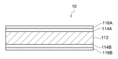
- the specific plated steel sheet has at least one plating layer selected from the group consisting of a GI plating layer and a Zn—Ni plating layer on a steel base material. Further, a zinc compound layer or a metal zinc layer may be further provided as the outermost layer on the plating layer.
- a plating layer specifically, a GI plating (hot-dip galvanized) layer or a Zn—Ni plating ( Zinc nickel plating) layers 114A and 114B, and zinc compound layers or metal zinc layers 116A and 116B as outermost layers on the plating layers 114A and 114B.
- a plating layer specifically, a GI plating (hot-dip galvanized) layer or a Zn—Ni plating ( Zinc nickel plating) layers 114A and 114B, and zinc compound layers or metal zinc layers 116A and 116B as outermost layers on the plating layers 114A and 114B.
- the steel sheet to be plated (steel sheet before plating, steel base material) has, for example, high mechanical strength (for example, tensile strength, yield point, elongation, drawing, hardness, impact value, fatigue strength, It means various properties related to mechanical deformation and fracture such as creep strength.).
- high mechanical strength for example, tensile strength, yield point, elongation, drawing, hardness, impact value, fatigue strength, It means various properties related to mechanical deformation and fracture such as creep strength.
- An example of a steel sheet (steel sheet before plating) that achieves high mechanical strength used for the plated steel sheet according to the present embodiment is as follows.
- the notation of% means mass% unless otherwise specified.
- a numerical range represented by using “to” means a range including numerical values described before and after “to” as a lower limit and an upper limit.
- the steel sheet is expressed by mass%: C: 0.01 to 0.6%, Si: 0.01 to 0.6%, Mn: 0.5 to 3%, Ti: 0.01 to 0.1%, and , B: preferably at least one of 0.0001 to 0.1%, and the balance being Fe and impurities.
- C is contained to secure the desired mechanical strength.
- C is less than 0.01%, sufficient improvement in mechanical strength cannot be obtained, and the effect of containing C becomes poor.
- C exceeds 0.6%, the steel sheet can be further hardened, but melt cracking is likely to occur. Therefore, the C content is preferably set to 0.01% or more and 0.6% or less.
- Si is one of the strength improving elements for improving the mechanical strength, and is contained in the same manner as C to secure the desired mechanical strength. If the content of Si is less than 0.01%, the effect of improving the strength is difficult to exert, and sufficient improvement in mechanical strength cannot be obtained. On the other hand, Si is also an easily oxidizable element. Therefore, when Si exceeds 0.6%, when performing GI plating or Zn-Ni plating, wettability may fall and nonplating may occur. Therefore, the Si content is preferably set to 0.01% or more and 0.6% or less.
- Mn is one of the strengthening elements for strengthening steel, and is also one of the elements for improving hardenability. Further, Mn is effective in preventing hot brittleness due to S, which is one of the impurities. If Mn is less than 0.5%, these effects cannot be obtained, and if 0.5% or more, the above effects are exhibited. On the other hand, when Mn exceeds 3%, there is a possibility that the residual ⁇ phase becomes too large and the strength is reduced. Therefore, the Mn content is preferably set to 0.5% or more and 3% or less.
- Ti is one of the strength enhancing elements, and is also an element for improving the heat resistance of the GI plating layer or the Zn—Ni plating layer.
- Ti is less than 0.01%, the effect of improving strength and the effect of improving oxidation resistance cannot be obtained, and these effects are exhibited at 0.01% or more.
- the Ti content is preferably set to 0.01% or more and 0.1% or less.
- B has the effect of improving strength by acting during quenching.
- B is less than 0.0001%, such a strength improving effect is low.
- B exceeds 0.1%, inclusions may be formed and become brittle, and the fatigue strength may be reduced. Therefore, the B content is preferably set to 0.0001% or more and 0.1% or less.
- this steel sheet may also contain impurities that are mixed in the manufacturing process or the like.
- a steel sheet formed of such a chemical component is quenched by heating such as hot press forming, and can have a mechanical strength of about 1500 MPa or more. Although it is a steel sheet having high mechanical strength in this way, if it is processed by hot press forming, it can be easily formed because hot press forming can be performed in a state softened by heating. Further, the steel sheet can realize high mechanical strength, and can maintain or improve the mechanical strength even if the steel sheet is thinned for weight reduction.
- the GI plating (hot-dip galvanized) layer will be described.
- a method of forming the GI plating layer for example, a forming method by a plating process of a reduction furnace method may be mentioned.
- a pretreatment process, an annealing process, and a plating process are performed.
- the method according to the present embodiment is not limited to the above-described embodiment, and for example, the plating process can be performed in a non-oxidizing furnace system.
- description will be given based on the reduction furnace method.
- the pretreatment is usually performed to remove oil (oil and fat) and dirt on the steel sheet surface, and is typically performed by alkali degreasing.
- the pretreatment method is not limited as long as the steel sheet surface is appropriately degreased.
- hot rinsing washing with warm water
- drying with a drier or the like are performed, for example, to remove the degreasing solution attached to the steel plate.
- the pretreated steel sheet is put into a reduction furnace, and is annealed (heat treatment in a reducing atmosphere) in the reduction furnace.
- the annealing conditions at this time are, for example, in the range of 500 to 700 ° C. (annealing temperature, soaking temperature), and the residence time (annealing time, soaking time) is 30 to 270 seconds. Annealing in the above temperature range is also called soaking.
- the atmosphere and the dew point at the time of the reduction are not particularly limited.
- the H 2 -N 2 mixed gas can be set to have a H 2 concentration of 1 to 30% and a dew point range of ⁇ 10 to ⁇ 60 ° C.
- the steel sheet exiting the reduction furnace is cooled in a cooling zone. Examples of the cooling method include a commonly used method such as cooling by blowing a gas in a reducing atmosphere onto a steel sheet.
- a GI plating (hot-dip galvanized) layer is formed by performing a hot-dip galvanizing process.
- the plating (hot-dip galvanizing) step is not particularly limited, and a commonly used method can be employed.
- the temperature of the hot-dip galvanizing bath may be controlled to about 430 to 500 ° C.
- a treatment such as a skin pass treatment, a tension leveler treatment, and an oil coating may be performed. Further, re-annealing may be performed after the hot-dip galvanizing treatment.
- the conditions for the re-annealing are preferably set to a heating temperature (re-annealing temperature) of 400 ° C. or higher, while the re-annealing temperature is preferably set to 750 ° C. or lower from the viewpoint of suppressing the evaporation of zinc.
- the time for maintaining the re-annealing temperature (re-annealing time) can be set as appropriate depending on the heating method and the like.
- the re-annealing time is preferably 1 hour or more (more preferably 2 hours or more), and in the case of induction heating, the re-annealing time is preferably 10 seconds or more.
- the re-annealing time is preferably 15 hours or less, more preferably 10 hours or less in the case of the furnace heating.
- the re-annealing time is preferably 3 minutes or less, more preferably 1 minute or less.
- the component composition of the GI plating layer may be a plating layer made of zinc, and a small amount of different metal elements or impurities (for example, cobalt, molybdenum, tungsten, nickel, titanium, chromium, aluminum, manganese, It may be a plating layer containing iron, magnesium, lead, bismuth, antimony, tin, copper, cadmium, arsenic, etc.). Further, it may further contain an inorganic substance such as silica, alumina and titania.
- a preferred component composition of the GI plating layer is, for example, a plating layer containing 0.01 to 0.20% by mass of Al in mass% and the balance consisting of Zn and impurities.
- the amount of the GI plating layer attached (the basis weight) is preferably 20 to 100 g / m 2 in terms of the amount of Zn.
- the adhesion amount of the GI plating layer is preferably 20 to 100 g / m 2 in terms of the amount of Zn.
- the adhesion amount of the GI plating layer is evaluated by the adhesion amount in terms of Zn amount.
- the measurement of the adhesion amount of the GI plating layer utilizes a fluorescent X-ray method. Specifically, a calibration curve is created by a fluorescent X-ray method using several types of standard samples whose adhesion amount (in terms of Zn amount) of the GI plating layer is known. Then, using the calibration curve, the Zn intensity of the sample to be measured is converted into the amount of adhesion of the GI plating layer to determine the amount of adhesion of the GI plating layer.
- Zn-Ni plating (zinc nickel plating) layer will be described.
- the component composition of the Zn—Ni plating layer may be a plating layer composed of zinc and nickel, and a small amount of other foreign metal elements or impurities (for example, cobalt, molybdenum, tungsten, titanium, chromium, aluminum, manganese). , Iron, magnesium, lead, bismuth, antimony, tin, copper, cadmium, arsenic, etc.). Further, it may further contain an inorganic substance such as silica, alumina and titania.
- the preferred component composition of the Zn—Ni plating layer is, for example, a plating layer containing 10 to 25% by mass of Ni and the balance being Zn and impurities.
- the adhesion amount (basis weight) of the Zn—Ni plating layer is 20 to 100 g / m 2 in terms of Zn amount.
- the adhesion amount of the Zn—Ni plating layer is 20 to 100 g / m 2 or more.
- an appropriate amount of zinc is adhered to the sliding surface of the die and the wear of the sliding surface of the die is reduced. Increase.
- the corrosion resistance of the press-formed product is increased.
- the adhesion amount of the Zn—Ni plating layer exceeds 100 g / m 2 , a large amount of zinc deposits adhere to the sliding surface of the mold, and the sliding surface of the die mold tends to be worn. Increase.
- the Zn—Ni plating layer may be a laminated plating layer in which two or more layers are laminated.
- the first layer lower layer
- the balance Zn and
- the plating layer is made of an impurity
- the second layer upper layer
- the plating layer is a plating layer containing 10 to 25% by mass of Ni in mass% and the balance being Zn and impurities.
- the adhesion amount (basis weight) of the first layer (lower layer) is preferably 0.01 to 5 g / m 2 in terms of Zn amount, and It is preferable that the adhesion amount (basis weight) of the eyes (lower layer) is 10 to 90 g / m 2 in terms of Zn amount.
- the adhesion amount of the Zn—Ni plating layer is evaluated based on the adhesion amount in terms of Zn amount.
- the measurement of the adhesion amount of the Zn—Ni plating layer utilizes a fluorescent X-ray method. Specifically, a calibration curve is created by a fluorescent X-ray method using several types of standard samples whose amounts of Zn—Ni plating layers (in terms of Zn amount) are known. Then, by using the calibration curve, the Zn intensity of the sample to be measured is converted into the amount of adhesion of the Zn—Ni plating layer, and the amount of adhesion of the Zn—Ni plating layer is obtained.
- the method for forming the Zn—Ni plating layer is not particularly limited, but a known electroplating method is preferable. The same applies to the case where two or more Zn—Ni plating layers are stacked. For example, by performing an electroplating process in a plating bath containing a nickel compound such as nickel sulfate hexahydrate and a zinc compound such as zinc sulfate heptahydrate, Zn—Ni is formed on a steel plate (steel base material). A plating layer can be formed. When two or more Zn—Ni plating layers are stacked, the respective plating layers can be formed in the same manner.
- the adjustment of the Ni content and the amount of adhesion (weight per unit area) and the like in each layer can be controlled by a known method. It can be controlled by adjusting the ratio, the current density in the plating bath, and the like.
- the zinc compound layer (Zn compound layer) or the metal zinc layer (metal Zn layer) is a ZnO film or a layer that becomes a ZnO film during hot press molding. Prior to hot press forming, the coated steel sheet is heated in an oxidizing atmosphere. At this time, a Zn compound layer or a metal Zn layer other than the ZnO film is oxidized to become a ZnO film.
- the Zn compound layer other than the ZnO film or the metal Zn layer is not particularly limited as long as it is oxidized into a ZnO film. Examples of the Zn compound layer other than the ZnO film include a zinc phosphate layer and a Zn-based metal soap layer.
- the Zn compound and the metal Zn may be mixed with a resin that is burned off by heating to form a Zn compound layer other than the ZnO film or a metal Zn layer.
- the amount of Zn contained in the Zn compound layer or the metal Zn layer is adjusted according to the amount of the ZnO film deposited on the target product.
- the ZnO film is a surface that comes into contact with the die and is an outer surface of the press-formed product.
- the method for forming the ZnO film is not particularly limited, and for example, can be formed on the plating layer by the methods described in Patent Documents 1 and 2.
- the amount of the ZnO film attached is preferably 0.4 to 4.0 g / m 2 in terms of Zn in terms of corrosion resistance of the product.
- the adhesion amount of the ZnO film is 0.4 g / m 2 or more in terms of Zn amount, the corrosion resistance of the press-formed product increases.
- the adhesion amount of the ZnO film exceeds 4.0 g / m 2 in terms of Zn amount, the thickness of the plating layer (GI plating layer or Zn—Ni plating layer) and the ZnO film becomes too thick, and the weldability and paint adhesion are increased. May deteriorate.
- the amount of the ZnO film attached is more preferably 0.4 to 2.0 g / m 2 in terms of Zn amount.
- the coating amount of the plating layer (GI plating layer or Zn—Ni plating layer) is low from the viewpoint of mold wear, it is desirable that the coating amount of the ZnO film is high in the above range.
- a fluorescent X-ray method is used as a method for measuring the amount of the ZnO film attached. Specifically, a calibration curve is created by a fluorescent X-ray method using several types of standard samples whose adhesion amount (in terms of Zn amount) of the ZnO film is known, and the Zn intensity of the sample to be measured is measured by the ZnO film. The amount of the ZnO film is calculated in terms of the amount of the ZnO film.
- the press-formed product according to the present embodiment is a press-formed product made of a steel plate.
- the steel sheet of the press-formed product includes a steel base material, and at least one plating layer selected from the group consisting of a hot-dip galvanized (GI plating) layer and a zinc nickel plating (Zn-Ni plating) layer on the steel base material; A zinc oxide (ZnO) layer as the outermost layer on the plating layer.
- the zinc oxide (ZnO) layer as the outermost layer is formed by heating when hot pressing is performed on the specific plated steel sheet.
- the steel base material (steel plate) has a hardness Hv_Parts of HV400 or more, preferably HV450 or more, and more preferably HV550 or more.
- the press-formed product according to the present embodiment includes a top plate portion, a vertical wall portion connected to the top plate portion via the first ridge line portion, and a flange portion connected to the vertical wall portion via the second ridge line portion.
- the press-formed product has a portion PB0 min where the radius of curvature of the flange portion projected on the press-formed product from a direction perpendicular to the longitudinal direction and parallel to the top plate portion is minimum.
- the press-formed product having the shape will be described.
- a formed product shown in FIGS. 2A and 2B is taken as an example.
- the hot press-formed product 30 shown in FIGS. 2A and 2B includes two vertical wall portions 33, a top plate portion 31 connecting the two vertical wall portions 33 via the first ridge line portion 32, and two vertical wall portions.
- the top plate portion 31 is a portion corresponding to the top surface of the punch during hot press forming
- the vertical wall portion 33 is a portion that slides on the punch and the die
- the flange portion 35 is a hot press. This is the part where molding by molding is not performed.
- the first ridgeline portion 32 is a curved portion connecting the top plate portion 31 and the vertical wall portion 33
- the second ridgeline portion 34 is a curved portion connecting the vertical wall portion 33 and the flange portion 35.
- the top plate portion 31 , The vertical wall portion 33 and the flange portion 35 are partially curved, and have a shape in which a portion is bulged toward the outside of the top plate portion 31. Therefore, in the flange portion 35 at the bulging portion, there is a portion PB0 min where the radius of curvature is minimum, and the press-formed product 30 is projected from a direction perpendicular to the longitudinal direction of the press-formed product 30 and parallel to the top plate portion 31.
- the radius of curvature of the entire flange portion 35 is not constant, and the top plate portion 31 has a shape in which the radius of curvature is not constant as a whole.
- the radius of curvature [R min ] at the point of the second ridgeline portion 34 where the radius of curvature is smallest is 3 mm or more and less than 10 mm.
- the fact that the minimum radius of curvature [R min ] at the second ridgeline portion 34 is less than 10 means that when the press-formed product 30 is manufactured by performing hot press forming on a specific plated steel sheet, the vertical wall portion 33 is formed.
- the three-dimensional shape on the outer surface of the second ridge portion 34 is measured by a three-dimensional shape measuring instrument. Then, the radius of curvature [R min ] at the location where the radius of curvature is the smallest in the cross section is obtained.
- a difference occurs in the smoothness between the top plate portion 31 and the vertical wall portion 33.
- the press-formed product 30 is projected from a direction orthogonal to the longitudinal direction of the press-formed product 30 and parallel to the top plate portion 31 (for example, as shown in FIG.
- the press-formed product 30 is projected from a direction orthogonal to the longitudinal direction of the press-formed product 30 and parallel to the top plate portion 31 (for example, as shown in FIG.
- the press-formed product 30 is projected from a direction orthogonal to the longitudinal direction of the press-formed product 30 and parallel to the top plate portion 31 (for example, as shown in FIG.
- the position corresponding to the point PB0 min where the radius of curvature of the flange portion 35 is minimum that is, when viewed from the y direction as shown in FIG.
- the position PB0 min on the flange portion 35 is a position that can be reached without being shifted in the x direction only by shifting in the z direction.
- the smoothness [SaB1] is measured.
- the vertical wall portion 33 when the press-formed product 30 is projected from a direction orthogonal to the longitudinal direction of the press-formed product 30 and parallel to the top plate portion 31, a portion corresponding to the location PB0 min (for example, FIG.
- the difference [SaB1-SaB2] in the smoothness between the top plate portion 31 and the vertical wall portion 33 is within the above range, when the press-formed product 30 is manufactured by performing hot press forming on a specific plated steel plate. 2 shows that a higher surface pressure is applied to the portion to be the vertical wall portion 33 than to the portion to be the top plate portion 31. This is because the surface of the vertical wall portion 33 is smoother than the top plate portion 31 due to the high surface pressure applied to the vertical wall portion 33 and sliding. Then, it can be said that this is a press-formed product that has been subjected to hot press-forming under conditions in which abrasion due to sliding is likely to occur in the vertical wall portion 33 where high surface pressure is applied.
- the difference [SaB1 ⁇ SaB2] of the smoothness is 0.40 ⁇ m or more, it can be said that the vertical wall portion 33 is more likely to cause abrasion due to sliding.
- the upper limit of the difference [SaB1-SaB2] of the smoothness is preferably 1.0 ⁇ m or less from the viewpoint of sharpness after coating.
- the smoothness [SaB1] and [SaB2] indicate the arithmetic average height Sa (unit: ⁇ m) defined in ISO25178-2 (2012).
- the measuring device and the measuring conditions are as follows. Measuring device: VK-X250 / 150 shape analysis laser microscope manufactured by KEYENCE CORPORATION Measuring range: 5 mm ⁇ 5 mm centering on the center point of PB1 min and PB2 min Measurement conditions: Use Gaussian filter S filter: Not used L filter: 4 mm
- the difference in the aspect ratio of the surface properties between the top plate portion 31 and the vertical wall portion 33 is small.
- the surface texture aspect ratio [StrB1] and the surface texture aspect ratio [StrB2] at the points PB1 min and PB2 min are the same as the above-described smoothness. Measure. As in the case of the smoothness, each is measured on the outer surface, that is, the surface that comes into contact with the die during hot press molding.
- the difference [StrB1-StrB2] is equal to or less than 0.50.
- the top plate portion 31 becomes closer to the portion that becomes the vertical wall portion 33 during hot press forming.
- the press-molded product has a reduced occurrence of abrasion due to sliding on the vertical wall portion 33, despite the fact that a higher surface pressure is applied than the portion where the pressure is applied.
- the abrasion due to sliding occurs remarkably, the abrasion is streak-like, and the aspect ratio Str of the surface texture at that portion decreases. Further, the portion where the abrasion occurs becomes a glossy portion before coating.
- the glossiness differs after the coating, it is visually recognized as a pattern, and the surface quality is inferior.
- the difference [StrB1 ⁇ StrB2] in the aspect ratio of the surface properties it is possible to realize the press-formed product according to the first aspect in which the difference in glossiness after coating is 25 or less, and to achieve excellent surface quality.
- a press-formed product using a steel base material having a hardness Hv_Parts of HV400 or more delayed fracture may occur due to hydrogen embrittlement or the like, particularly at a location where stress is concentrated during the press forming. Easy to occur.
- the concentration of stress on the vertical wall portion 33 is also suppressed. I can say. For this reason, delayed fracture, which is likely to occur at a stress concentration location, is also suppressed.
- the surface property aspect ratio difference [StrB1-StrB2] is preferably 0.50 or less, more preferably 0.40 or less, from the viewpoint of excellent surface quality and suppression of delayed fracture.
- the surface texture aspect ratios [StrB1] and [StrB2] refer to the surface texture aspect ratio Str defined in ISO25178-2 (2012).
- the measuring device and the measuring conditions are as follows. Measuring device: VK-X250 / 150 shape analysis laser microscope manufactured by KEYENCE CORPORATION Measuring range: 5 mm ⁇ 5 mm centering on the center point of PB1 min and PB2 min Measurement conditions: Use Gaussian filter S filter: Not used L filter: 4 mm
- the method of controlling the difference [StrB1 ⁇ StrB2] in the aspect ratio of the surface properties of the top plate portion 31 and the vertical wall portion 33 within the above range is not particularly limited.
- a method for forming a press-formed product by the method for producing a hot press-formed product according to the embodiment is exemplified.
- adhesion to a die is suppressed.
- the coefficient of friction increases, and abrasion due to sliding tends to occur.
- the decrease in the amount of adhered substance also suppresses an increase in the coefficient of friction, and the vertical wall portion 33 Generation of scratches due to sliding is suppressed.
- the difference [Str1-Str2] in the aspect ratio of the surface texture can be controlled in the above range.
- FIGS. 3A and 3B and FIGS. 4A and 4B are taken as an example.
- the hot press-formed product 40 shown in FIGS. 3A and 3B has two vertical wall portions 43, a flat top plate portion 41 connecting the two vertical wall portions 43 through the first ridge line portion 42, and two vertical wall portions.
- a flange portion 45 connected to the wall portion 43 on a side opposite to the top plate portion 41 via the second ridge line portion 44.
- the top plate portion 41 is a portion corresponding to the top surface of the punch during hot press forming
- the vertical wall portion 43 is a portion that slides on the punch and the die
- the flange portion 45 is a hot press. This is the part where molding by molding is not performed.
- the first ridge line portion 42 is a curved portion connecting the top plate portion 41 and the vertical wall portion 43
- the second ridge line portion 44 is a curved portion connecting the vertical wall portion 43 and the flange portion 45.
- the hot press-formed product 40 when a cross section (cross section, for example, the cross section shown in FIG. 3B) in a direction orthogonal to the longitudinal direction (x direction) is observed, the cut cross section is observed where Are also symmetrical. Further, the hot press-formed product 40 has a shape in which the radius of curvature of the second ridge portion 44 has the same value no matter where the cross section cut is observed. In other words, the radius of curvature of the second ridge line portion 44 is constant regardless of the cross section where it is cut. In other words, the radius of curvature of the second ridge line portion 44 is the minimum value wherever the cross section is cut.
- the hot press-formed product 50 shown in FIGS. 4A and 4B is a center pillar for an automobile, and has two vertical wall portions 53a and 53b and two vertical wall portions 53a and 53b having first ridge portions 52a and 52b, respectively.
- a flat top plate portion 51 connected to the top plate portion 51 and flange portions 55a and 55b connected to the two vertical wall portions 53a and 53b on the opposite side to the top plate portion 51 via the second ridge lines 54a and 54b, respectively.
- the top plate portion 51 is a portion corresponding to the top surface of the punch at the time of hot press forming
- the vertical wall portions 53a and 53b are portions that slide with the punch and the die, and the flange portions 55a and 55b.
- the first ridges 52a and 52b are curved portions connecting the top plate 51 and the vertical walls 53a and 53b, and the second ridges 54a and 54b are formed by the vertical walls 53a and 53b and the flanges 55a and 55b. This is a curved portion that connects.
- the hot press-formed product 50 when a cross section (cross section) in a direction orthogonal to the longitudinal direction (x direction) is observed, there are portions where the left and right shapes are not symmetric. For example, in the cross section shown in FIG.
- the heights in the z direction of the two first ridge lines 52 a and 52 b present on both sides of the flat top plate 51 are different, and the first ridge 52 a on the right is on the left.
- This is a shape that is higher than the first ridge line portion 52b in the z direction.
- the height of the two flange portions 55a and 55b in the z direction is also different, and the right flange portion 55a has a higher shape than the left flange portion 55b.
- the hot press-formed product 50 has a shape in which the radius of curvature of the second ridges 54a and 54b differs depending on the location where the cross section is cut when the cross section is observed, and the cross section shown in FIG. This is a shape in which the radius of curvature of the second ridge line portion 54a in the (B ′ cross section) is minimized.
- the radius of curvature [R min ] at the point where the radius of curvature is the smallest (that is, the point where bending is stricter) in the second ridgeline portion 44, 54a or 54b is 3 mm or more. It is less than 10 mm.
- the fact that the minimum radius of curvature [R min ] at the second ridge line portion 44, 54a or 54b is less than 10 means that the press-formed products 40 and 50 are manufactured by performing hot press forming on a specific plated steel sheet. 5 shows that a high surface pressure is applied to a portion to be the vertical wall portion 43, 53a or 53b.
- this is a press-formed product that has been subjected to hot press-forming under conditions in which abrasion due to sliding is likely to occur in the vertical wall portion 43, 53a or 53b where high surface pressure is applied.
- the upper limit of the minimum radius of curvature [R min ] at the second ridge line portion 44, 54a or 54b is 8 mm or less, it can be said that the vertical wall portion 43, 53a or 53b is more likely to cause abrasion due to sliding.
- the lower limit of the minimum radius of curvature [R min ] at the second ridge portion 44, 54a or 54b is 3 mm or more, and preferably 4 mm or more, from the viewpoint of preventing cracking during press molding.
- the measurement of the radius of curvature is performed in accordance with the method of measuring the radius of curvature at the second ridgeline in the first embodiment.
- a difference in smoothness occurs between the top plate portion and the vertical wall portion.
- the cross section of the press molded article where the radius of curvature of the second ridge line becomes minimum is measured. And That is, in the case of the press-formed product 40 shown in FIGS.
- the radius of curvature of the second ridge line portion 44 is the minimum value in any cross section cut at any location, and any cross section may be a measurement target, and is preferably Is recommended to have a cross section at the center position in the longitudinal direction (x direction).
- the radius of curvature of the second ridge portion 54a in the cross section (BB ′ cross section in FIG. 4A) shown in FIG. 4B is minimized.
- the cross section shown in FIG. 4B is a measurement target. Then, in the cross section where the radius of curvature is minimum, the center of the top plate portion (41, 51) in the cross sectional width direction (for example, in the case of FIG.
- the measurement is performed on the outer surface of each of the points PA1 min and PA2 min , that is, the surface that is in contact with the die during hot press forming.
- the difference [SaA1-SaA2] is 0.25 ⁇ m or more.
- the smoothness [SaA1] at the center point PA1 min in the width direction of the cross section of the top plate portion and the cross section of the vertical wall portion is 0.35 ⁇ m or more.
- the difference [SaA1-SaA2] in the smoothness between the top plate portion and the vertical wall portion is within the above range, which means that when a specific plated steel sheet is subjected to hot press forming to produce a press-formed product, This indicates that a higher surface pressure is applied to the wall portion than to the top plate portion. This is because the surface of the vertical wall portion becomes smoother than the top plate portion due to the high surface pressure applied to the vertical wall portion and sliding. Then, it can be said that this is a press-formed product that has been subjected to hot press-forming under conditions in which abrasion due to sliding is likely to occur on the vertical wall portion where high surface pressure is applied.
- the difference in smoothness [SaA1-SaA2] is 0.45 ⁇ m or more, it can be said that abrasion due to sliding on the vertical wall portion is more likely to occur.
- the upper limit of the difference in smoothness [SaA1-SaA2] is more preferably 1.0 ⁇ m or less from the viewpoint of sharpness after coating.
- the smoothness [SaA1] and [SaA2] indicate the arithmetic average height Sa (unit: ⁇ m) defined in ISO25178-2 (2012).
- the measuring device and the measuring conditions are as follows. Measuring device: VK-X250 / 150 shape analysis laser microscope manufactured by KEYENCE CORPORATION Measuring range: 5 mm ⁇ 5 mm centering on the center point of PA1 min and PA2 min Measurement conditions: Use Gaussian filter S filter: Not used L filter: 4 mm
- the difference in the aspect ratio of the surface properties between the top plate portion and the vertical wall portion is small.
- the portions PA1 min and PA2 In min the surface texture aspect ratio [StrA1] and the surface texture aspect ratio [StrA2] are measured.
- each is measured on the outer surface, that is, the surface that comes into contact with the die during hot press molding.
- the difference [StrA1-StrA2] is equal to or less than 0.50.
- the smaller the difference [StrA1-StrA2] in the aspect ratio of the surface properties between the top plate portion and the vertical wall portion the smaller the difference between the top plate portion and the portion that becomes the vertical wall portion during hot press forming. This indicates that the press-molded product has suppressed generation of abrasion due to sliding in the vertical wall portion despite high surface pressure.
- the abrasion due to sliding occurs remarkably, the abrasion is streak-like, and the aspect ratio Str of the surface texture at that portion decreases. Further, the portion where the abrasion occurs becomes a glossy portion before coating.
- the press-formed product according to the second embodiment in which the difference in glossiness after coating is 25 or less, can be realized, and excellent surface quality can be achieved.
- a press-formed product using a steel base material having a hardness Hv_Parts of HV400 or more delayed fracture may occur due to hydrogen embrittlement or the like, particularly at a location where stress is concentrated during the press forming. Easy to occur.
- the surface property aspect ratio difference [StrA1-StrA2] is preferably 0.50 or less, more preferably 0.40 or less, from the viewpoint of excellent surface quality and suppression of delayed fracture.
- the surface texture aspect ratios [StrA1] and [StrA2] refer to the surface texture aspect ratio Str defined in ISO25178-2 (2012).
- the measuring device and the measuring conditions are as follows. Measuring device: VK-X250 / 150 shape analysis laser microscope manufactured by KEYENCE CORPORATION Measuring range: 5 mm ⁇ 5 mm centering on the center point of PA1 min and PA2 min Measurement conditions: Use Gaussian filter S filter: Not used L filter: 4 mm
- the method of controlling the difference [StrA1-StrA2] in the aspect ratio of the surface properties between the top panel and the vertical wall to be in the above range is not particularly limited.
- a method of forming a press-formed product by such a method of manufacturing a hot press-formed product is exemplified.
- adhesion to a die is suppressed.
- the coefficient of friction increases, and abrasion due to sliding tends to occur.
- the decrease in the amount of adhered substance also suppresses an increase in the coefficient of friction, and the vertical wall slides. The generation of scratches due to movement is suppressed.
- the difference [Str1-Str2] in the aspect ratio of the surface texture can be controlled in the above range.
- the average thickness of the zinc oxide (ZnO) layer as the outermost layer is preferably from 0.3 ⁇ m to 2.0 ⁇ m, and more preferably from 0.4 ⁇ m to 1.5 ⁇ m. It is more preferred that: Note that the average thickness referred to here means a place where sliding is small during hot press forming, specifically, a press formed product 30, 40, or 50 shown in FIG. 2A, FIG. 3B, or FIG. It refers to the thickness of the ZnO layer inside the plate portion 31, 41, or 51. When the average thickness of the ZnO layer is 0.3 ⁇ m or more, adhesion to a die during hot press molding is suppressed.
- the average thickness of the ZnO layer is 2.0 ⁇ m or less, excellent weldability is obtained, and high corrosion resistance is maintained because the GA plating layer does not become too thin.
- the average thickness of the ZnO layer can be adjusted by the heating holding time during hot press forming or by applying a ZnO coating before forming.
- the average thickness of the ZnO layer is measured at a place where sliding is small during hot press molding as described above. Specifically, the thickness is measured by the following method. The press-formed product is cut in a cross section, and the structure of the plating layer in the outermost layer of the top plate portion in the cross section is observed and analyzed using an electron microscope JSM-7001F manufactured by JEOL. Then, the thickness in the thickness direction of the maximum portion of the thickness of the ZnO layer existing on the outermost surface is measured. In addition, it measures about three places inside the top board part selected at random, and takes the average value.
- GI-plated steel sheet >> ⁇ GI plated steel sheet (G1)> 1.6 mm cold-rolled steel sheet (by mass%, C: 0.21%, Si: 0.12%, Mn: 1.21%, P: 0.02%, S: 0.012%, Ti : 0.02%, B: 0.03%, Al: 0.04%, and the balance: Fe and impurities) as a steel base material, and both surfaces of the steel base material are subjected to a GI plating process of a reduction furnace method. A GI plating layer was formed.
- a pretreatment was performed on the steel base material by alkali degreasing, followed by hot rinsing (washing with warm water) and drying with a dryer.
- the pretreated steel base material was put into a reduction furnace, annealed in a reducing atmosphere, and cooled.
- a GI plating (hot-dip galvanized) layer was formed on this steel base material by forming a hot-dip galvanized layer in a hot-dip galvanizing bath.
- a test material of the GI-plated steel sheet (A1) was obtained.
- the component composition of the GI plating layer is such that, by mass%, it contains 0.1% of Al and the balance consists of Zn and impurities.
- G2 A test material of a GI-plated steel sheet was obtained in the same manner as the GI-plated steel sheet (G1), except that the adhesion amounts (weight per unit area) on the upper and lower surfaces of the GI plating layer were changed as shown in Table 1 below. .
- Example A Example of GI-plated steel sheet
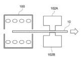
- Production of die mold >> ⁇ Condition No. 1A: Comparative Example A1> -Base material Steel of the material described in Table 1 is prepared, and is roughly processed in an annealed state into a shape similar to the upper die 102A and the lower die 102B shown in FIG. After quenching by cooling, it was tempered at 540 to 580 ° C. to temper to 64 HRC. After that, finishing was performed to obtain a base material of the die. The base material itself was used as a die (upper die 102A and lower die 102B) without forming a nitride layer and a PVD film.
- the skewness (Rsk) in the sliding direction of the plated steel sheet 10 contacting (sliding) on the steel sheet contact surface of the obtained die was measured by the method described above.
- the hardness Hv_Die of the obtained steel die contact surface of the die was measured by the above-described method.
- the below-mentioned evaluation was implemented using the plated steel plate and the die shown in Table 2.
- Example A1> -Formation of nitride layer A nitride layer was formed on the steel sheet contact surface of the base material (upper die 102A and lower die 102B) obtained in Condition No. 1A, which contacted (slided) with the plated steel sheet 10.
- the base material was subjected to an ion nitriding treatment under the following conditions. That is, after performing an ion nitriding treatment in a 5% N 2 (remaining H 2 ) atmosphere at a flow rate of 5 ° C. for 5 hours, each test surface was finished by polishing to form a nitrided layer.
- polishing was performed by sliding a grinding
- Table 2 shows the skewness (Rsk) in the sliding direction with the plated steel sheet 10 on the steel plate contact surface of the obtained die and the hardness Hv_Die on the steel plate contact surface.
- the below-mentioned evaluation was implemented using the plated steel plate and the die shown in Table 2.
- Example A4> In condition No. 2A, after performing the ion nitriding treatment, a nitride layer was formed without polishing the test surface. Then, a PVD film as a hard coating layer was formed on the nitrided layer.
- a bias voltage of -400 V was applied to the base material in a Ar atmosphere at a pressure of 0.5 Pa using an arc ion plating apparatus at a position where the nitride layer of the base material was formed, and a heat of 60 minutes was applied. Plasma cleaning with a filament was performed. Thereafter, a PVD film is formed at a base material temperature of 500 ° C., a reaction gas pressure of 3.0 Pa, and a bias voltage of ⁇ 50 V, using a metal target as an evaporation source of the metal component and N 2 gas as a reaction gas.
- the metal target as the evaporation source used had a metal composition capable of forming a PVD film satisfying the composition shown in Table 2.
- polishing was performed by sliding the polishing sheet in a direction in which the polishing sheet was in contact (sliding) with the plated steel sheet 10 on the steel sheet contact surface.
- Table 2 shows the skewness (Rsk) in the sliding direction with the plated steel sheet 10 on the steel plate contact surface of the obtained die and the hardness Hv_Die on the steel plate contact surface. Furthermore, the below-mentioned evaluation was implemented using the plated steel plate and the die shown in Table 2.
- Example A5 and Comparative Examples A2 to A7> The composition of the PVD film was as shown in Table 2 below, and the hardness of the PVD film was adjusted to the value shown in Table 2 below. Further, in condition No. 5A, by changing the degree of polishing of the PVD film, the skewness (Rsk) in the sliding direction with the plated steel plate 10 on the steel plate contact surface of the die becomes the value shown in Table 2 below.
- the die molds (upper die 102A and lower die 102B) were prepared by the above adjustments. Furthermore, the below-mentioned evaluation was implemented using the plated steel plate and the die shown in Table 2.
- Example A6> Under condition number 2A, the hardness of the nitrided layer was adjusted to the values shown in Table 2 below. Further, by changing the degree of polishing of the nitride layer, the skewness (Rsk) in the sliding direction with the plated steel sheet 10 on the steel plate contact surface of the die mold is adjusted to be a value shown in Table 2 below. Die dies (upper die 102A and lower die 102B) were produced. Furthermore, the below-mentioned evaluation was implemented using the plated steel plate and the die shown in Table 2.
- condition number 1A by changing the degree of polishing of the steel plate contact surface, the skewness (Rsk) in the sliding direction with the plated steel plate 10 on the steel plate contact surface of the die becomes a value shown in Table 2 below. After adjustment, die dies (upper die 102A and lower die 102B) were produced. Furthermore, the below-mentioned evaluation was implemented using the plated steel plate and the die shown in Table 2.
- the hot lubricity evaluation device shown in FIG. 6 includes a near-infrared heating furnace 100 and a mold including an upper mold 102A and a lower mold 102B.
- the upper mold 102A and the lower mold 102B each have a protrusion having a width of 10 mm that extends in a direction perpendicular to the direction in which the plated steel sheet is drawn out. Apply the pressing load.
- the hot lubricating property evaluation apparatus is also provided with a plated steel sheet heated by the near-infrared heating furnace 100 and a thermocouple (not shown) for measuring the temperature of the plated steel sheet when sandwiched by a mold. I have.
- reference numeral 10 denotes a test material of a plated steel sheet.
- a test material having a temperature of about 650 ° C.
- the sample was pulled out while applying a pressing load of 3 kN (that is, sliding the test material against the die) with a die composed of the upper die 102A and the lower die 102B.
- the drawing length was 100 mm and the drawing speed was 40 mm / s.
- the average heating rate when heating to 920 ° C. was 7.5 ° C./sec.
- the amount of wear was measured. Specifically, the profile of the mold surface in the sliding portion before and after the sliding was measured using a contact-type shape measuring machine, and the mold wear was measured. The mold wear was calculated by calculating the average wear from the profiles of the surfaces of the upper mold and the lower mold, and the average value was calculated. From the obtained mold wear amount, evaluation was made according to the following evaluation criteria. A: Mold wear amount 0.5 ⁇ m or less B: Mold wear amount 0.5 ⁇ m or more and 1 ⁇ m or less C: Mold wear amount 1 ⁇ m or more and 2 ⁇ m or less D: Mold wear amount 2 ⁇ m or more
- Adhesion to the mold was evaluated by the following test.
- the amount of adhesion was measured. Specifically, the profile of the mold surface at the sliding part before and after sliding was measured using a contact-type shape measuring instrument, and the adhesion height at the position where the height of the adhesion part of the adhesion was maximum was measured. (Hereinafter, the maximum adhesion height of the mold) was measured.
- the maximum adhesion height of the mold was the maximum value of the adhesion heights of the upper mold and the lower mold. From the obtained maximum adhesion height of the mold, evaluation was made according to the following evaluation criteria. A: Maximum die adhesion height of 0.5 ⁇ m or less B: Maximum die adhesion height of more than 0.5 ⁇ m and 1 ⁇ m or less C: Maximum die adhesion height of more than 1 ⁇ m and 3 ⁇ m or less D: Maximum die adhesion height Over 3 ⁇ m
- the friction coefficient between the mold and the steel sheet was evaluated by the following test. After the above-described hot lubricity evaluation test, the coefficient of friction between the steel sheet contact surface of the “die of the hot lubricity measuring device” and the plated steel sheet 10 was measured by the following method. During the above-described evaluation test of hot lubricity, the pull-out load was measured, and the friction coefficient was calculated using the pressing load and the measured pull-out load.
- Molded product number 8A to 10A This is an example in which the base material strength of the press-formed product is different.
- ⁇ Molded product number 11A This is an example where the thickness (average thickness) of the ZnO layer is large.
- Zn-Ni plated steel sheet >> ⁇ Zn-Ni plated steel sheet (Z1)> 1.6 mm cold-rolled steel sheet (by mass%, C: 0.21%, Si: 0.12%, Mn: 1.21%, P: 0.02%, S: 0.012%, Ti : 0.02%, B: 0.03%, Al: 0.04%, and the balance: Fe and impurities) as a steel base material, and Zn-Ni plating by electroplating on both surfaces of the steel base material A layer was formed.
- a test material of the Zn—Ni plated steel sheet (Z1) was obtained.
- the composition of the Zn—Ni plating layer is 12% by mass of Ni in mass%, and the balance is composed of Zn and impurities.
- Z2 ⁇ Zn-Ni plated steel sheet (Z2)> A Zn—Ni plated steel sheet was prepared in the same manner as the Zn—Ni plated steel sheet (Z1) except that the amount of adhesion (weight per unit area) on the upper and lower surfaces of the Zn—Ni plated layer was changed as shown in Table 4 below. The test material was obtained.
- Z3 ⁇ Zn-Ni plated steel sheet (Z3)> A laminated Zn—Ni plated steel sheet in which two plating layers were laminated was formed. The first (lower) and second (upper) Zn—Ni plating layers were formed on both surfaces of the steel base material obtained from the Zn—Ni plated steel sheet (Z1) by electroplating.
- the current density is adjusted to perform an electroplating process, and the lower Zn—Ni plating A layer was formed.
- the component composition of the lower layer contains 60% by mass of Ni in mass%, and the balance consists of Zn and impurities.
- the current density is adjusted to perform an electroplating treatment, and the Zn—Ni plating layer is formed.
- the composition of the Zn—Ni plating layer is 12% by mass of Ni in mass%, and the balance is composed of Zn and impurities.
- Example C (Example of Zn-Ni plated steel sheet)- ⁇ Production of die mold >> ⁇ Condition No. 1C: Comparative Example C1> -Base material Steel of the material described in Table 4 is prepared, and is roughly processed in an annealed state into a shape similar to the upper die 102A and the lower die 102B shown in FIG. After quenching by cooling, it was tempered at 540 to 580 ° C. to temper to 64 HRC. After that, finishing was performed to obtain a base material of the die. The base material itself was used as a die (upper die 102A and lower die 102B) without forming a nitride layer and a PVD film.
- the skewness (Rsk) in the sliding direction of the plated steel sheet 10 contacting (sliding) on the steel sheet contact surface of the obtained die was measured by the method described above.
- the hardness Hv_Die of the obtained steel die contact surface of the die was measured by the above-described method. Furthermore, the following evaluation was implemented using the plated steel sheet and the die shown in Table 5.
- Example C1> -Formation of nitrided layer A nitrided layer was formed on the steel plate contact surface of the base material (upper die 102A and lower die 102B) obtained in Condition No. 1C, which contacted (slided) with plated steel sheet 10.
- the base material was subjected to an ion nitriding treatment under the following conditions. That is, after performing an ion nitriding treatment in a 5% N 2 (remaining H 2 ) atmosphere at a flow rate of 5 ° C. for 5 hours, each test surface was finished by polishing to form a nitrided layer.
- polishing was performed by sliding a grinding
- Table 5 shows the skewness (Rsk) in the sliding direction with the plated steel sheet 10 on the steel plate contact surface of the obtained die and the hardness Hv_Die on the steel plate contact surface.
- the following evaluation was implemented using the plated steel sheet and the die shown in Table 5.
- Example C4> In condition No. 2C, after performing the ion nitriding treatment, a nitride layer was formed without polishing the test surface. Then, a PVD film as a hard coating layer was formed on the nitrided layer.
- a bias voltage of -400 V was applied to the base material in a Ar atmosphere at a pressure of 0.5 Pa using an arc ion plating apparatus at a position where the nitride layer of the base material was formed, and a heat of 60 minutes was applied. Plasma cleaning with a filament was performed. Thereafter, a PVD film is formed at a base material temperature of 500 ° C., a reaction gas pressure of 3.0 Pa, and a bias voltage of ⁇ 50 V, using a metal target as an evaporation source of the metal component and N 2 gas as a reaction gas.
- the metal target as the evaporation source a metal target that forms a PVD film satisfying the composition shown in Table 5 was used.
- polishing was performed by sliding the polishing sheet in a direction in which the polishing sheet was in contact (sliding) with the plated steel sheet 10 on the steel sheet contact surface.
- Table 5 shows the skewness (Rsk) in the sliding direction with the plated steel sheet 10 on the steel plate contact surface of the obtained die and the hardness Hv_Die on the steel plate contact surface. Furthermore, the following evaluation was implemented using the plated steel sheet and the die shown in Table 5.
- Example C5 and Comparative Examples C2 to C7> The composition of the PVD film was as shown in Table 5 below, and the hardness of the PVD film was adjusted to the value shown in Table 5 below.
- condition No. 5C by changing the degree of polishing of the PVD film, the skewness (Rsk) in the sliding direction with the plated steel plate 10 on the steel plate contact surface of the die becomes the value shown in Table 5 below.
- the die molds (upper die 102A and lower die 102B) were prepared by the above adjustments. Furthermore, the following evaluation was implemented using the plated steel sheet and the die shown in Table 5.
- Example C6> Under condition number 2C, the hardness of the nitrided layer was adjusted to a value shown in Table 5 below. Further, by changing the degree of polishing of the nitrided layer, the skewness (Rsk) in the sliding direction with the plated steel sheet 10 on the steel sheet contact surface of the die mold is adjusted to a value shown in Table 5 below. Die dies (upper die 102A and lower die 102B) were produced. Furthermore, the following evaluation was implemented using the plated steel sheet and the die shown in Table 5.
- the hot lubricity evaluation device shown in FIG. 6 includes a near-infrared heating furnace 100 and a mold including an upper mold 102A and a lower mold 102B.
- the upper mold 102A and the lower mold 102B each have a protrusion having a width of 10 mm that extends in a direction perpendicular to the direction in which the plated steel sheet is drawn out. Apply the pressing load.
- the hot lubricating property evaluation apparatus is also provided with a plated steel sheet heated by the near-infrared heating furnace 100 and a thermocouple (not shown) for measuring the temperature of the plated steel sheet when sandwiched by a mold. I have.
- reference numeral 10 denotes a test material of a plated steel sheet.
- a specimen of 30 mm ⁇ 500 mm was heated at 920 ° C. in a nitrogen atmosphere by a near-infrared heating furnace 100, and then the specimen at about 700 ° C. was heated. Then, the sample was pulled out while applying a pressing load of 3 kN (that is, sliding the test material against the mold) with the mold composed of the upper mold 102A and the lower mold 102B.
- the drawing length was 100 mm and the drawing speed was 40 mm / s.
- the average heating rate when heating to 920 ° C. was 7.5 ° C./sec.
- the amount of wear was measured. Specifically, the profile of the mold surface in the sliding portion before and after the sliding was measured using a contact-type shape measuring machine, and the mold wear was measured. The mold wear was calculated by calculating the average wear from the profiles of the surfaces of the upper mold and the lower mold, and the average value was calculated. From the obtained mold wear amount, evaluation was made according to the following evaluation criteria. A: Mold wear amount 0.5 ⁇ m or less B: Mold wear amount 0.5 ⁇ m or more and 1 ⁇ m or less C: Mold wear amount 1 ⁇ m or more and 2 ⁇ m or less D: Mold wear amount 2 ⁇ m or more
- Adhesion to the mold was evaluated by the following test.
- the amount of adhesion was measured. Specifically, the profile of the mold surface at the sliding part before and after sliding was measured using a contact-type shape measuring instrument, and the adhesion height at the position where the height of the adhesion part of the adhesion was maximum was measured. (Hereinafter, the maximum adhesion height of the mold) was measured.
- the maximum adhesion height of the mold was the maximum value of the adhesion heights of the upper mold and the lower mold. From the obtained maximum adhesion height of the mold, evaluation was made according to the following evaluation criteria. A: Maximum die adhesion height of 0.5 ⁇ m or less B: Maximum die adhesion height of more than 0.5 ⁇ m and 1 ⁇ m or less C: Maximum die adhesion height of more than 1 ⁇ m and 3 ⁇ m or less D: Maximum die adhesion height Over 3 ⁇ m
- the friction coefficient between the mold and the steel sheet was evaluated by the following test. After the above-described hot lubricity evaluation test, the coefficient of friction between the steel sheet contact surface of the “die of the hot lubricity measuring device” and the plated steel sheet 10 was measured by the following method. During the above-described evaluation test of hot lubricity, the pull-out load was measured, and the friction coefficient was calculated using the pressing load and the measured pull-out load.
- Example D Production of press-formed product using Zn-Ni plated steel sheet- ⁇ Production of die mold
- a press-formed product whose shape is shown in FIGS. 2A and 2B is formed.
- the base material is changed to a shape having a radius of curvature [R min ] at a point where the radius of curvature is minimum at the second ridge line portion has a value shown in Table 6 below.
- a die mold was manufactured in the same manner as in the condition numbers in “Example C” except that the hardness Hv_Die in the vertical wall portion was changed to that shown in Table 6 below.
- the forming part of the nitride layer and the PVD film was formed over the entire region where the material is expected to be in contact with the mold during press forming.
- Molded product number 8C-10C This is an example in which the base material strength of the press-formed product is different.
- ⁇ Molded product number 11C This is an example where the thickness (average thickness) of the ZnO layer is large.
Priority Applications (4)
| Application Number | Priority Date | Filing Date | Title |
|---|---|---|---|
| CN201980038036.XA CN112236243B (zh) | 2018-07-04 | 2019-07-03 | 热压成型品的制造方法、压制成型品、冲模模具及模具套件 |
| JP2019559863A JP6648875B1 (ja) | 2018-07-04 | 2019-07-03 | 熱間プレス成形品の製造方法、プレス成形品、ダイ金型、及び金型セット |
| MX2020013493A MX2020013493A (es) | 2018-07-04 | 2019-07-03 | Metodo de fabricacion de articulo formado por prensado en caliente, articulo formado por prensado, matriz y conjunto de matriz. |
| US15/733,831 US11491528B2 (en) | 2018-07-04 | 2019-07-03 | Hot press-formed item manufacturing method, press-formed item, die, and die set |
Applications Claiming Priority (2)
| Application Number | Priority Date | Filing Date | Title |
|---|---|---|---|
| JP2018-127893 | 2018-07-04 | ||
| JP2018127893 | 2018-07-04 |
Publications (1)
| Publication Number | Publication Date |
|---|---|
| WO2020009171A1 true WO2020009171A1 (ja) | 2020-01-09 |
Family
ID=69060883
Family Applications (1)
| Application Number | Title | Priority Date | Filing Date |
|---|---|---|---|
| PCT/JP2019/026536 WO2020009171A1 (ja) | 2018-07-04 | 2019-07-03 | 熱間プレス成形品の製造方法、プレス成形品、ダイ金型、及び金型セット |
Country Status (5)
| Country | Link |
|---|---|
| US (1) | US11491528B2 (zh) |
| JP (1) | JP6648875B1 (zh) |
| CN (1) | CN112236243B (zh) |
| MX (1) | MX2020013493A (zh) |
| WO (1) | WO2020009171A1 (zh) |
Citations (3)
| Publication number | Priority date | Publication date | Assignee | Title |
|---|---|---|---|---|
| JPH05115930A (ja) * | 1991-10-24 | 1993-05-14 | Dowa Mining Co Ltd | 金型処理法 |
| JP2015205328A (ja) * | 2014-04-22 | 2015-11-19 | 株式会社神戸製鋼所 | Znめっき鋼板の熱間成形用金型 |
| WO2016171273A1 (ja) * | 2015-04-23 | 2016-10-27 | 日立金属株式会社 | 被覆金型およびその製造方法 |
Family Cites Families (16)
| Publication number | Priority date | Publication date | Assignee | Title |
|---|---|---|---|---|
| JPH10137861A (ja) * | 1996-11-05 | 1998-05-26 | Sky Alum Co Ltd | 絞りしごき加工法 |
| CN2429278Y (zh) * | 2000-06-14 | 2001-05-09 | 周水军 | 一种制造电子元器件金属外壳用金刚石膜拉深模具 |
| JP4085876B2 (ja) * | 2003-04-23 | 2008-05-14 | 住友金属工業株式会社 | 熱間プレス成形品およびその製造方法 |
| JP2005305510A (ja) * | 2004-04-22 | 2005-11-04 | Sumitomo Metal Ind Ltd | プレス型工具 |
| AU2009238926B2 (en) | 2008-04-22 | 2012-03-29 | Nippon Steel Corporation | Plated steel sheet and method of hot-pressing plated steel sheet |
| JP5351875B2 (ja) * | 2010-11-30 | 2013-11-27 | 株式会社神戸製鋼所 | 塑性加工用金型およびその製造方法、ならびにアルミニウム材の鍛造方法 |
| WO2012144318A1 (ja) * | 2011-04-18 | 2012-10-26 | 日本高周波鋼業株式会社 | プレス成形用金型及びプレス成形金型用保護膜の製造方法 |
| JP5582254B2 (ja) * | 2012-02-14 | 2014-09-03 | 新日鐵住金株式会社 | めっき鋼板の熱間プレス方法 |
| EP2946848B1 (en) * | 2013-01-18 | 2018-07-25 | Kabushiki Kaisha Kobe Seiko Sho (Kobe Steel, Ltd.) | Manufacturing method for hot press formed steel member |
| EP2980262A4 (en) * | 2013-04-18 | 2016-11-23 | Nippon Steel & Sumitomo Metal Corp | PLATED STEEL PLATE FOR HOT PRESSING, METHOD FOR HOT PRESSING A PLATED STEEL PLATE AND AUTOMOTIVE PARTS |
| JP5825413B1 (ja) * | 2014-04-23 | 2015-12-02 | Jfeスチール株式会社 | 熱間プレス成形品の製造方法 |
| WO2017029773A1 (ja) | 2015-08-19 | 2017-02-23 | Jfeスチール株式会社 | 熱間プレス部材の製造方法および熱間プレス部材 |
| WO2017033791A1 (ja) * | 2015-08-26 | 2017-03-02 | 東洋製罐グループホールディングス株式会社 | しごき加工用ダイス及びダイスモジュール |
| JP2017110248A (ja) * | 2015-12-15 | 2017-06-22 | 株式会社神戸製鋼所 | 硬質皮膜及び金型 |
| WO2018097286A1 (ja) * | 2016-11-28 | 2018-05-31 | 日立金属株式会社 | 金型およびその製造方法 |
| WO2019198728A1 (ja) | 2018-04-13 | 2019-10-17 | 日本製鉄株式会社 | 熱間プレス成形品の製造方法、プレス成形品、ダイ金型、及び金型セット |
-
2019
- 2019-07-03 US US15/733,831 patent/US11491528B2/en active Active
- 2019-07-03 WO PCT/JP2019/026536 patent/WO2020009171A1/ja active Application Filing
- 2019-07-03 CN CN201980038036.XA patent/CN112236243B/zh active Active
- 2019-07-03 JP JP2019559863A patent/JP6648875B1/ja active Active
- 2019-07-03 MX MX2020013493A patent/MX2020013493A/es unknown
Patent Citations (3)
| Publication number | Priority date | Publication date | Assignee | Title |
|---|---|---|---|---|
| JPH05115930A (ja) * | 1991-10-24 | 1993-05-14 | Dowa Mining Co Ltd | 金型処理法 |
| JP2015205328A (ja) * | 2014-04-22 | 2015-11-19 | 株式会社神戸製鋼所 | Znめっき鋼板の熱間成形用金型 |
| WO2016171273A1 (ja) * | 2015-04-23 | 2016-10-27 | 日立金属株式会社 | 被覆金型およびその製造方法 |
Also Published As
| Publication number | Publication date |
|---|---|
| CN112236243A (zh) | 2021-01-15 |
| JP6648875B1 (ja) | 2020-02-14 |
| CN112236243B (zh) | 2023-04-04 |
| MX2020013493A (es) | 2022-05-04 |
| JPWO2020009171A1 (ja) | 2020-07-09 |
| US20210252580A1 (en) | 2021-08-19 |
| US11491528B2 (en) | 2022-11-08 |
Similar Documents
| Publication | Publication Date | Title |
|---|---|---|
| JP7081662B2 (ja) | 熱間プレス成形品の製造方法、プレス成形品、ダイ金型、及び金型セット | |
| JP6369659B1 (ja) | 熱間プレス用めっき鋼板、熱間プレス用めっき鋼板の製造方法、熱間プレス成形品の製造方法、及び車両の製造方法 | |
| JP6648874B1 (ja) | 熱間プレス成形品の製造方法、プレス成形品、ダイ金型、及び金型セット | |
| JP6648875B1 (ja) | 熱間プレス成形品の製造方法、プレス成形品、ダイ金型、及び金型セット | |
| JP4843973B2 (ja) | 塗装後鮮映性に優れる溶融亜鉛めっき鋼板 | |
| KR102460884B1 (ko) | 핫스탬핑용 피복 금형 | |
| JPH0718402A (ja) | プレス成形性および塗装後鮮映性に優れた合金化溶融亜鉛めっき鋼板 | |
| JP4039332B2 (ja) | 耐パウダリング性、摺動性および塗装後鮮映性に優れた合金化溶融亜鉛めっき鋼板およびその製造方法 | |
| WO2021215418A1 (ja) | 熱間プレス成形品の製造方法及び熱間プレス成形品 | |
| JP3979275B2 (ja) | プレス成形性に優れた溶融亜鉛めっき鋼板の製造方法 | |
| KR20010059366A (ko) | 내식성 및 도장선영성이 우수한 용융아연도금강판 제조방법 | |
| JP2001247950A (ja) | プレス成形性に優れた溶融亜鉛めっき鋼板およびその製造方法 |
Legal Events
| Date | Code | Title | Description |
|---|---|---|---|
| ENP | Entry into the national phase |
Ref document number: 2019559863 Country of ref document: JP Kind code of ref document: A |
|
| 121 | Ep: the epo has been informed by wipo that ep was designated in this application |
Ref document number: 19830421 Country of ref document: EP Kind code of ref document: A1 |
|
| NENP | Non-entry into the national phase |
Ref country code: DE |
|
| 122 | Ep: pct application non-entry in european phase |
Ref document number: 19830421 Country of ref document: EP Kind code of ref document: A1 |