WO2020009171A1 - Hot press-formed item manufacturing method, press-formed item, die, and die set - Google Patents
Hot press-formed item manufacturing method, press-formed item, die, and die set Download PDFInfo
- Publication number
- WO2020009171A1 WO2020009171A1 PCT/JP2019/026536 JP2019026536W WO2020009171A1 WO 2020009171 A1 WO2020009171 A1 WO 2020009171A1 JP 2019026536 W JP2019026536 W JP 2019026536W WO 2020009171 A1 WO2020009171 A1 WO 2020009171A1
- Authority
- WO
- WIPO (PCT)
- Prior art keywords
- die
- layer
- steel sheet
- press
- mold
- Prior art date
Links
Images


Classifications
-
- B—PERFORMING OPERATIONS; TRANSPORTING
- B21—MECHANICAL METAL-WORKING WITHOUT ESSENTIALLY REMOVING MATERIAL; PUNCHING METAL
- B21D—WORKING OR PROCESSING OF SHEET METAL OR METAL TUBES, RODS OR PROFILES WITHOUT ESSENTIALLY REMOVING MATERIAL; PUNCHING METAL
- B21D22/00—Shaping without cutting, by stamping, spinning, or deep-drawing
- B21D22/20—Deep-drawing
- B21D22/26—Deep-drawing for making peculiarly, e.g. irregularly, shaped articles
-
- B—PERFORMING OPERATIONS; TRANSPORTING
- B21—MECHANICAL METAL-WORKING WITHOUT ESSENTIALLY REMOVING MATERIAL; PUNCHING METAL
- B21D—WORKING OR PROCESSING OF SHEET METAL OR METAL TUBES, RODS OR PROFILES WITHOUT ESSENTIALLY REMOVING MATERIAL; PUNCHING METAL
- B21D37/00—Tools as parts of machines covered by this subclass
- B21D37/10—Die sets; Pillar guides
-
- B—PERFORMING OPERATIONS; TRANSPORTING
- B21—MECHANICAL METAL-WORKING WITHOUT ESSENTIALLY REMOVING MATERIAL; PUNCHING METAL
- B21D—WORKING OR PROCESSING OF SHEET METAL OR METAL TUBES, RODS OR PROFILES WITHOUT ESSENTIALLY REMOVING MATERIAL; PUNCHING METAL
- B21D22/00—Shaping without cutting, by stamping, spinning, or deep-drawing
- B21D22/20—Deep-drawing
- B21D22/208—Deep-drawing by heating the blank or deep-drawing associated with heat treatment
-
- B—PERFORMING OPERATIONS; TRANSPORTING
- B21—MECHANICAL METAL-WORKING WITHOUT ESSENTIALLY REMOVING MATERIAL; PUNCHING METAL
- B21D—WORKING OR PROCESSING OF SHEET METAL OR METAL TUBES, RODS OR PROFILES WITHOUT ESSENTIALLY REMOVING MATERIAL; PUNCHING METAL
- B21D24/00—Special deep-drawing arrangements in, or in connection with, presses
- B21D24/04—Blank holders; Mounting means therefor
-
- B—PERFORMING OPERATIONS; TRANSPORTING
- B21—MECHANICAL METAL-WORKING WITHOUT ESSENTIALLY REMOVING MATERIAL; PUNCHING METAL
- B21D—WORKING OR PROCESSING OF SHEET METAL OR METAL TUBES, RODS OR PROFILES WITHOUT ESSENTIALLY REMOVING MATERIAL; PUNCHING METAL
- B21D37/00—Tools as parts of machines covered by this subclass
- B21D37/01—Selection of materials
Definitions
- the present disclosure relates to a method for manufacturing a hot press-formed product, a press-formed product, a die, and a die set.
- Most of the vehicle body structure is made of iron, especially steel plate. It is required to reduce the weight of the vehicle body while maintaining the strength of the structural material made of the steel sheet.
- the demand for such steel sheets is made not only in the automobile manufacturing industry but also in various manufacturing industries. Therefore, by increasing the mechanical strength of the steel sheet, it is possible to maintain or increase the mechanical strength of the structural material even when the steel sheet is thinner than conventionally used steel sheets.
- a material having high mechanical strength tends to have a reduced shape freezing property in a forming process such as a bending process. That is, when processing into a complicated shape, the processing itself becomes difficult.
- hot press forming hot press method, high temperature press method, die quench method
- a steel sheet to be formed is once heated to a high temperature, pressed and formed on a steel sheet softened by heating, and then cooled.
- the hot press forming since the steel sheet is once heated to a high temperature and softened, the steel sheet can be easily pressed. Furthermore, the mechanical strength of the steel sheet can be increased by the quenching effect of cooling after forming. Therefore, by this hot press molding, a molded product having both good shape freezing property and high mechanical strength can be obtained.
- Patent Literature 1 discloses a zinc oxide film (hereinafter also referred to as a “ZnO film”) or the like for the purpose of improving chemical conversion treatment and corrosion resistance in addition to hot lubrication to prevent generation of processing flaws.
- ZnO film a zinc oxide film
- a method for forming a film of a wurtzite compound on the surface of an Al-plated steel sheet is disclosed.
- Patent Literature 2 discloses a coating of one or more Zn compounds selected from the group consisting of Zn hydroxide, Zn phosphate, and organic acid Zn in order to enhance the adhesion of the ZnO coating during press molding. Is formed on the surface of an Al-plated steel sheet.
- a ZnO film is generated by heat when hot-press-forming an Al-plated steel sheet on which a Zn compound film is formed, a ZnO film having excellent adhesion is formed, and hot lubrication is performed. Properties, film adhesion, spot weldability, and corrosion resistance after painting can be improved.
- Patent Document 3 discloses a coating mold having a hard coating on the surface, wherein the hard coating includes an A layer made of a nitride having a thickness of 5 ⁇ m or more and a B layer made of a diamond-like carbon film.
- the layer B is on the outer surface side of the layer A, and the surface of the layer B satisfies an arithmetic average roughness Ra ⁇ 0.2 ⁇ m, a maximum height Rz ⁇ 2.0 ⁇ m, and a skewness Rsk ⁇ 0.
- a mold is disclosed.
- Patent Document 1 International Publication No. WO 2009/131233
- Patent Document 2 Japanese Patent Application Publication No. 2014-139350
- Patent Document 3 International Publication No. WO 2016/171273
- the plated steel sheets of Patent Documents 1 and 2 are all excellent in hot lubricity and can suppress generation of processing flaws.
- a slide of a hot press forming die on which the plated steel sheet slides such as a portion that becomes a vertical wall portion and a flange portion of the pressed product. Wear occurs on the moving surface. For this reason, in the high surface pressure portion of the hot press molding, mold care is required to cope with abrasion occurring on the sliding surface of the mold.
- An object of the present disclosure is to reduce wear of a sliding surface of a die when hot press-forming a plated steel sheet having at least one plating layer selected from the group consisting of a hot-dip galvanized layer and a zinc-nickel plated layer.
- An object of the present invention is to provide a method for producing a hot press-formed product, which suppresses generation. Further, the problem of the present disclosure is to provide a die set that suppresses the occurrence of wear on the sliding surface, a die set of a die die and a punch die, and a die set of a die die and a steel plate holding die. To provide.
- Another object of the present disclosure is to provide a press-formed product having excellent surface quality and suppressing occurrence of delayed fracture.
- the gist of the present disclosure is as follows. ⁇ 1> A method for producing a hot press-formed product, Placing a plated steel sheet having at least one type of plating layer selected from the group consisting of a hot-dip galvanized layer and a zinc-nickel plated layer on the die mold by closing a die hole of the die, and the plated steel sheet Hot press forming using the die mold, Has, The die mold is provided on the outer surface of the die hole and in a steel sheet contact surface that comes into contact with the plated steel sheet before being subjected to the hot press forming.
- the hard layer is a layer including a nitride layer and a hard coating layer on a surface of the nitride layer.
- ⁇ 4> The method for producing a hot press-formed product according to any one of ⁇ 1> to ⁇ 3>, wherein the plated steel sheet has a zinc compound layer or a metal zinc layer as an outermost layer on the plated layer.
- a steel sheet press-formed product The steel sheet has a steel base material having a hardness Hv_Parts of HV400 or more, at least one plating layer selected from the group consisting of a hot-dip galvanized layer and a zinc nickel plated layer on the steel base material, and A zinc oxide layer as the outermost layer,
- the press-formed product has a top plate, a vertical wall connected to the top plate via a first ridge, and a flange connected to the vertical wall via a second ridge.
- the radius of curvature [R min ] at a point where the radius of curvature is minimum in the second ridgeline portion is 3 mm or more and less than 10 mm
- SaB2] is 0.35 ⁇ m or more;
- the difference [StrB1-StrB2] between the aspect ratio [StrB1] of the surface texture at the location PB1 min on the top plate portion and the aspect ratio [StrB2] of the surface texture at the location PB2 min on the vertical wall portion is obtained.
- ⁇ 7> Used for hot press forming of a plated steel sheet having at least one type of plating layer selected from the group consisting of a galvanized layer and a zinc nickel plating layer,
- the skewness (Rsk) measured in the direction from the outside to the inside of the die hole is ⁇ 5 in the entire region adjacent to the die shoulder in the outer surface of the die hole and the surface adjacent to the die shoulder adjacent to the die shoulder.
- ⁇ 8> The die according to ⁇ 7>, wherein the hard layer is a layer having a nitride layer as an outermost layer.
- the hard layer is a layer including a nitride layer and a hard coating layer on a surface of the nitride layer.
- ⁇ 10> Used for hot press forming of a plated steel sheet having at least one type of plating layer selected from the group consisting of a galvanized layer and a zinc nickel plating layer, A die mold according to any one of ⁇ 7> to ⁇ 9>, and a punch mold, The punch die is directed inward from the outside of the punch portion to an entire region of the opposing surface opposing the die shoulder adjacent surface of the die die, where the die die opposes the portion having the hard layer.
- the second hard layer is a layer having a second nitride layer as an outermost layer.
- the second hard layer is a layer including a second nitride layer and a second hard coating layer on a surface of the second nitride layer.
- ⁇ 13> Used for hot press forming of a plated steel sheet having at least one type of plating layer selected from the group consisting of a galvanized layer and a zinc nickel plating layer, A die including the die according to any one of ⁇ 7> to ⁇ 9> and a steel plate holding die, The steel plate holding mold is provided such that the entire surface of the die surface facing the die shoulder adjacent surface of the die die facing the portion where the die die has the hard layer is provided from the outside to the inside of the punch insertion portion.
- the wear of the sliding surface of the die mold is reduced. It is possible to provide a method for producing a hot press-formed product that suppresses generation. Further, according to the present disclosure, a die, a die set of a die die and a punch die, and a die set of a die die and a steel plate holding die, which suppress the occurrence of wear of a sliding surface. Can be provided. Further, according to the present disclosure, it is possible to provide a press-formed product having excellent surface quality and suppressing occurrence of delayed fracture.
- FIG. 2 is a schematic view (perspective view) showing an example of a press-formed product obtained by hot press forming shown in FIG. 1.
- FIG. 2 is a schematic view (side view) showing an example of a press-formed product obtained by the hot press forming shown in FIG. 1.
- FIG. 4A It is a schematic diagram which shows another example of the press-formed product obtained by the hot press-forming concerning this embodiment. It is a schematic diagram which shows an example of the plating steel plate hot-press-molded by a die die and a punch die. It is an outline sectional view showing an example of the plating steel plate used for this embodiment. It is a schematic block diagram which shows the evaluation apparatus of hot lubricity.
- the “longitudinal direction of the press-formed product” is defined as the x direction.
- the x direction is a direction along a line connecting the centers of gravity of the ends in the longitudinal direction of the top plate.
- the “direction perpendicular to the longitudinal direction of the press-formed product and parallel to the top plate” is defined as the y direction.
- the y direction is a direction along a line connecting the first ridge lines in a cross section of the press-formed product orthogonal to the longitudinal direction.
- a method for manufacturing a hot press-formed product according to an embodiment of the present disclosure will be described.
- the manufacturing method of the hot press molded product according to the present embodiment A plated steel sheet having at least one type of plating layer selected from the group consisting of a hot-dip galvanized (hereinafter, also simply referred to as “GI plating”) layer and a zinc-nickel plating (hereinafter, also simply referred to as “Zn—Ni plating”) layer is formed by a die. Closing the die hole of the die and disposing it on the die, and hot-press-forming the plated steel sheet using the die.
- GI plating hot-dip galvanized
- Zn—Ni plating zinc-nickel plating
- the plated steel sheet may have only the GI plating layer as the plating layer, may have only the Zn—Ni plating layer, and may have the GI plating layer and the Zn—Ni plating layer. It may be an embodiment having both.
- the die mold is provided on the entire surface adjacent to the die shoulder portion of the steel plate contact surface that is in contact with the specific plated steel plate before hot press forming on the outer surface of the die hole.
- the hard layer has a skewness (Rsk) measured in a direction from the outside to the inside of the hole of ⁇ 5.0 to 1.2 and a hardness Hv_Die of HV1000 to 1550.
- the plated steel sheet When the plated steel sheet is placed on the die with the die hole of the die closed, the plated steel sheet may cover the whole or part of the die hole.
- the plated steel sheet when forming the cup-shaped hat material shown in FIG. 5, the plated steel sheet is arranged so as to cover all the die holes.
- the plated steel sheet When forming the grooved hat material of FIG. 2, the plated steel sheet is arranged so as to partially close the die hole. That is, the end of the plated steel sheet is disposed across the die hole.
- the method for manufacturing a hot press-formed product according to the present embodiment suppresses the occurrence of abrasion on the sliding surface of the die in the high surface pressure portion during the hot press forming, by the above-described configuration. And the manufacturing method of the hot press molded article concerning this embodiment was discovered by the knowledge shown below.
- a specific plated steel sheet (a plated steel sheet in which at least one of a GI plating layer and a Zn—Ni plating layer is provided on both surfaces of a steel sheet) of the related art for hot press forming is hot press-formed
- the GI plating layer or the Zn -Seizure occurs in which the zinc of the Ni plating layer reacts with the material (iron) of the die.
- Intermetallic compounds (zinc deposits) generated by this seizure sometimes adhered in large quantities to the surface of the die.
- Patent Documents 1 and 2 disclose a plated steel sheet having a ZnO film formed on the surface of a plating layer provided on both sides of a steel sheet (hereinafter referred to as a “plated steel sheet with a ZnO film”) for the purpose of suppressing the adhesion of the adhered matter to the die. ”) Has been proposed. Since the surface of the plated layer of the plated steel sheet with the ZnO film is covered with the ZnO film, even when hot press-forming, the adhesion of the adhered matter to the surface of the die mold due to seizure is suppressed. As a result, the coefficient of friction with the surface of the die is reduced.
- the mold wears even with the ZnO film.
- a high surface pressure is applied to a region adjacent to the die shoulder on the surface that slides on the plated steel sheet during hot press forming. Therefore, when the specific plated steel sheet is used irrespective of the presence or absence of the ZnO film, abrasion may occur on the sliding surface of the die.
- the outer surface of the die hole of the die, and the steel plate contact surface in contact with the specific plated steel plate before hot press forming is adjacent to the die shoulder. It has a hard layer in all areas.
- the skewness (Rsk) of the hard layer measured from the outside to the inside of the die hole is ⁇ 5.0 or more and 1.2 or less.
- the skewness Rsk is an index defined in JIS B 0601 (2001) and represents the symmetry of the peak and the valley with respect to the average line. When this Rsk is positive (0 ⁇ Rsk), it indicates a state where the peaks and valleys are unevenly distributed below the average line.
- the hard layer has a hardness Hv_Die of HV1000 or more and 1550 or less.
- the method for manufacturing a hot press-formed product according to the present embodiment is a method for manufacturing a hot press-formed product in which a plated steel sheet is heated, then pressed by a die, and hot press-formed. Then, in hot press forming, a plated steel sheet heated to a high temperature is press-formed by a mold. Thereafter, by cooling, a press-formed product having a desired shape is obtained. The hot press forming is performed after the plated steel sheet is placed on the die with the die hole closed.
- -Hot press molding- In press forming a steel sheet is drawn into a die hole of a die and formed.
- the edge of the die hole (die shoulder) is curved to protrude toward the outside of the die hole, the steel plate shrinks and deforms as it is drawn into the die hole.
- the thickness of the steel sheet increases as it approaches the edge of the die hole (die shoulder).
- a high surface pressure is applied to the steel sheet.
- wrinkles occur in the steel sheet as the steel sheet approaches the edge of the die hole (die shoulder).
- the die according to the present embodiment includes a hard layer at a position where a high surface pressure occurs.
- FIG. 1 shows a die die, a holder (a steel plate holding die), and a plated steel plate that is hot press-formed by a punch.
- 2A and 2B show a hot press-formed product formed by the die of FIG.
- FIG. 1 is a cross-sectional view corresponding to a cross section in the y direction when the hot press-formed product 30 shown in FIG. 2A is formed by a die.
- the longitudinal direction of the hot press-formed product 30 is defined as an x direction
- a direction observed from the vertical wall portion 33 side in a direction orthogonal to the x direction is defined as a y direction.
- a direction perpendicular to the direction and observed from the top 31 is defined as a z-direction.
- the hot press-formed product 30 shown in FIGS. 2A and 2B includes two vertical wall portions 33, a top plate portion 31 connecting the two vertical wall portions 33 via the first ridge line portion 32, and two vertical wall portions. And a flange portion 35 connected to the opposite side of the top plate portion 31 via the second ridgeline portion 34 with respect to the flange 33.
- the shape has a portion PB0 min where the radius of curvature is minimum.
- the flange portion 35 has a curved portion in the longitudinal direction (x direction), and the radius of curvature of the entire flange portion 35 is not constant. Further, similarly to the flange portion 35, the top plate portion 31 also has a curved portion in the longitudinal direction (x direction).
- the hot press-formed product formed by the die according to the present embodiment is not limited to the shape shown in FIGS. 2A and 2B.
- a molded product having a flat top plate and a flat flange may be used.
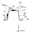
- FIG. 3B is a sectional view taken along the line AA ′ in FIG. 3A. 3A and 3B, the longitudinal direction of the hot press-formed product 40 is defined as the x direction, and the direction observed from the vertical wall portion 43 side among the directions orthogonal to the x direction is defined as the y direction, and is orthogonal to the x direction and the y direction. And the direction of observation from the top plate 41 side is the z direction.
- the hot press-formed product 40 shown in FIGS. 3A and 3B includes two vertical wall portions 43, a top plate portion 41 connecting the two vertical wall portions 43 via the first ridge line portion 42, and two vertical wall portions. And a flange 45 connected to the top 43 at a side opposite to the top plate 41 via the second ridge 44.
- a cross section cross section, for example, the cross section shown in FIG. 3B
- the cross section cut is observed, also has a shape in which the radius of curvature of the second ridgeline portion 44 has the same value.
- the shape is symmetrical.
- the hot press-formed product formed by the die according to the present embodiment is not limited to a symmetrical shape in a cross section as shown in FIGS. 3A and 3B.
- a molded product having different shapes on the left and right in a cross-sectional view may be used.
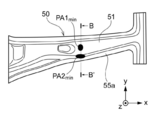
- FIG. 4B is a sectional view taken along the line BB ′ in FIG. 4A. 4A and 4B, the longitudinal direction of the hot press-formed product 50 is defined as the x direction, and among the directions orthogonal to the x direction, the direction observed from the side of the vertical wall 53a is defined as the y direction, and is orthogonal to the x direction and the y direction.
- the hot press-formed product 50 shown in FIGS. 4A and 4B has a top plate portion 51 connecting two vertical wall portions 53a, 53b and two vertical wall portions 53a, 53b via first ridge portions 52a, 52b, respectively. And flange portions 55a and 55b which are connected to the two vertical wall portions 53a and 53b via the second ridge portions 54a and 54b on the side opposite to the top plate portion 51, respectively.
- a cross section cross section in a direction orthogonal to the longitudinal direction (x direction) is observed, there are portions where the left and right shapes are not symmetric. For example, in the cross section shown in FIG.
- the heights in the z direction of the two first ridge lines 52 a and 52 b present on both sides of the flat top plate 51 are different, and the first ridge 52 a on the right is on the left. This is a shape that is higher than the first ridge line portion 52b in the z direction.
- the height of the two flange portions 55a and 55b in the z direction is also different, and the right flange portion 55a has a higher shape than the left flange portion 55b.
- the hot press-formed product 50 has a shape in which the radii of curvature of the second ridges 54a and 54b are different depending on the position to be cut when the cross section is observed, and the second ridges in the cross section shown in FIG. 4B.
- 54a has a shape with a minimum radius of curvature.
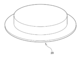
- hot press-formed products for example, hot press-formed products 30
- a punch 13 is pressed against a plated steel plate 10 and inserted into a die hole 11D. Then, the plated steel sheet 10 flows into the die hole 11D. At this time, as the plated steel plate 10 approaches the die hole 11D, the flange is shrunk and deformed to increase the thickness of the hot press-formed product 20.
- FIG. 1 In FIG. 1, during hot press-forming, a punch 13 is pressed against a plated steel plate 10 and inserted into a die hole 11D. Then, the plated steel sheet 10 flows into the die hole 11D. At this time, as the plated steel plate 10 approaches the die hole 11D, the flange is shrunk and deformed to increase the thickness of the hot press-formed product 20.
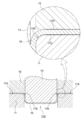
- a die mold (die) 11 is provided on a die shoulder 11 ⁇ / b> B of a steel plate contact surface 11 ⁇ / b> A which is on the outer surface of a die hole 11 ⁇ / b> D and is in contact with a plated steel plate 10 before hot press forming.
- the hard layer 11C is provided in all adjacent regions. When the hard layer 11C satisfies the skewness (Rsk) and the hardness Hv_Die, abrasion occurs on the sliding surface of the die 11 at a high surface pressure portion when a specific plated steel sheet is hot pressed. Is suppressed.
- the holder (steel plate holding die) 12 is provided with a second hard metal in an entire area of the opposing surface of the die 11 that faces the steel contact surface 11A, where the die 11 has the hard layer 11C. It is desirable to have layer 12C.
- the second hard layer 12C satisfies the skewness (Rsk) and the hardness Hv_Die, abrasion occurs on the sliding surface of the holder 12 at the high surface pressure portion when hot pressing the specific plated steel sheet. Is suppressed.
- the hard layer 11 ⁇ / b> C is preferably formed over the entire area along the die shoulder 11 ⁇ / b> B.
- a portion where a particularly high surface pressure occurs may be selected to form the hard layer 11C.
- the second hard layer 12C is formed over the entire area along a location facing the die shoulder 11B of the die mold 11.
- a portion where a particularly high surface pressure occurs may be selected to form the second hard layer 12C.
- the shape of the hot press-formed product to be formed is not limited to the shapes shown in FIGS. 2A and 2B, 3A and 3B, 4A and 4B, and the like.
- a press-formed product having various other shapes such as a hat-shaped press-formed product shown in FIG. 5 can be manufactured.
- the entire area adjacent to the die shoulder portion of the steel plate contact surface which is in contact with the specific plated steel sheet before hot press forming on the outer surface of the die hole as a die for use in the press forming, the entire area adjacent to the die shoulder portion of the steel plate contact surface which is in contact with the specific plated steel sheet before hot press forming on the outer surface of the die hole.
- the die in the high surface pressure portion is formed. The occurrence of wear on the sliding surface is suppressed.
- the hot press forming method in the hot press forming, for example, after blanking (punching) as necessary, the coated steel sheet is softened by heating to a high temperature. Then, the softened plated steel sheet is pressed and formed using a mold, and then cooled. Thus, in the hot press forming, the subsequent pressing can be easily performed by softening the plated steel sheet once.
- the hot-pressed press-formed product is quenched by heating and cooling, and becomes a high tensile strength molded product of about 1500 MPa or more.
- a heating method for hot press molding in addition to a normal electric furnace and a radiant tube furnace, a heating method using infrared heating, electric heating, induction heating, or the like can be used. Heating is performed in an oxidizing atmosphere.
- the die according to the present embodiment is used for hot press forming of a specific plated steel sheet having at least one of a GI plating layer and a Zn—Ni plating layer.
- a die for hot press forming a GI plated steel sheet having a GI plated layer as the outermost layer, or a GI plated steel sheet having a zinc compound layer or a metal zinc layer as the outermost layer on the GI plated layer Hot press forming is performed on a Zn-Ni plated steel sheet having a Zn-Ni plated layer as the outermost layer or a Zn-Ni plated steel sheet having a zinc compound layer or a metallic zinc layer as the outermost layer on the Zn-Ni plated layer.
- the skewness (Rsk) measured in the direction from the outside to the inside of the die hole in all the regions adjacent to the die shoulder in the surface outside the die hole and the surface adjacent to the die shoulder adjacent to the die shoulder.
- a hard layer having a hardness of not less than ⁇ 5.0 and not more than 1.2 and not less than ⁇ 5.0 and a hardness Hv_Die of not less than HV1000 and not more than 1550.
- a steel plate that is on the outer surface of the die hole and contacts a specific plated steel plate before hot-press forming.
- the skewness (Rsk) measured from the outside to the inside of the die hole in the direction from the outside to the inside of the die hole, and the hardness Hv_Die is HV1000 to 1550 in the entire area of the contact surface adjacent to the die shoulder. It has the following hard layer.
- the skewness (Rsk) of the hard layer is more preferably 1.0 or less, and further preferably 0.8 or less.
- the lower limit of the skewness (Rsk) of the hard layer is -5.0 or more, more preferably -3, from the viewpoint of suppressing an increase in manufacturing cost due to surface control for reducing the skewness (Rsk). 0.0 or more.
- the skewness Rsk is measured according to JIS B 0601 (2001). Specifically, the skewness Rsk is measured under the following measurement conditions in accordance with JIS B 0601 (2001).
- Measurement condition Measuring device: Mitutoyo Co., Ltd. “Surface roughness / contour shape measuring instrument Form Tracer” Measurement length L: 9.6 mm Cutoff wavelength ⁇ c: 0.8 mm Stylus tip shape: Tip angle 60 ° cone Stylus tip radius: 2 ⁇ m Measuring speed: 1mm / sec
- the method of controlling the skewness (Rsk) measured from the outside to the inside of the die hole in the hard layer to the above range is not particularly limited.
- the surface of the formed hard layer is polished, and at the time of this polishing, polishing is performed in a direction from the outside to the inside of the die hole (that is, a direction in which the plated steel plate slides during hot press forming).
- the polishing is performed by sliding the polishing sheet, there is a method in which the direction in which the polishing sheet is slid is a direction from the outside to the inside of the die hole.
- Hardness Hv_Die When the hardness Hv_Die of the hard layer included in the die is not less than HV1000, the occurrence of wear on the sliding surface of the die in the high surface pressure part during hot press forming is suppressed.
- the hardness Hv_Die of the hard layer is more preferably HV1200 or more.
- the upper limit of the hardness Hv_Die of the hard layer is HV1550 or less. By being HV 1550 or less, scraping of the GI plating layer or the Zn—Ni plating layer in the specific plated steel sheet, and in the case of having a zinc compound layer or a metal zinc layer, further suppressing the scraping of the zinc compound layer or the metal zinc layer. You.
- the hardness Hv_Die refers to a Vickers hardness specified by JIS-Z-2244 (2009), and in this specification, a hardness value under a test load of 0.2452 N in a Vickers hardness test method. is there. HM-115 manufactured by Mitutoyo Corporation is used for the micro Vickers tester.
- the material and the forming method of the hard layer formed on the die are not limited as long as they satisfy the skewness Rsk and the hardness Hv_Die described above.
- the hard layer include a layer having a nitride layer as the outermost layer.
- a layer having a hard coating layer (more preferably, a laminated hard layer including a nitride layer and a hard coating layer on the surface of the nitride layer) may be mentioned.
- the formation of the nitrided layer is preferably performed by a surface hardening treatment using diffusion, for example, a nitridation treatment.
- the formation of the nitrided layer is performed, for example, by subjecting the base material of the die to ion nitriding, that is, performing ion nitriding by adjusting the temperature in an atmosphere of a predetermined concentration of N 2 and H 2 gas.
- a compound layer called a nitride layer called a white layer formed by the nitriding treatment causes a decrease in adhesiveness
- the compound layer is prevented from being formed by controlling the processing conditions, or is removed by polishing or the like. It is desirable to do.
- the hard coating layer examples include a deposited film formed by physical vapor deposition (PVD).
- PVD physical vapor deposition
- CVD chemical vapor deposition
- the physical vapor deposition method for example, an arc ion plating method and a sputtering method are desirable.
- a film containing at least one of Ti and Cr is preferably used as the deposited film as the hard coating layer.
- the metal element portion is any one of a nitride, a carbide, and a carbonitride mainly composed of one or more selected from Ti, Cr, and Al. Further, it is more preferable that the metal element portion is any of a nitride, a carbide and a carbonitride mainly composed of Ti or Cr.
- the ratio of Ti, Cr or Al (or Ti or Cr) is 70 (at.%) Or more in the ratio of only the metal (including semimetal) composition part, excluding nitrogen and carbon. Further, the content is preferably 90 (at.%) Or more (including substantially 100 (at.%)).
- the deposited film as the hard coating layer is formed by, for example, adjusting the temperature and gas pressure using various metal targets and reaction gases (N 2 gas, CH 4 gas, etc.), which are evaporation sources of metal components, and adjusting the Bias voltage.
- a PVD film can be formed on the surface of the base material of the die.
- Specific examples include a nitride film, a carbide film, a carbonitride film, and a diamond-like carbon (DLC) film mainly composed of one or more selected from Ti, Cr and Al.
- a laminated hard layer including a nitrided layer and a hard coating layer on the surface of the nitrided layer is formed, for example, by forming a nitrided layer by the above-mentioned method, and then further by a hard coating layer (for example, a vapor-deposited film) by the above-described method. Is obtained.
- the metal material of the base material of the die is not particularly specified, and known metal materials such as cold die steel, hot die steel, high-speed steel, and cemented carbide can be used.
- improved metal types that have been proposed as steel types that can be used in conventional dies including standard metal types (steel types) according to JIS and the like, can also be applied.
- a mold set is a combination of a die mold and a punch mold having a convex portion corresponding to a die hole of the die mold and a facing surface facing a steel plate contact surface (adjacent surface of the die) of the die mold. It is. Also, the mold set is a steel plate holding mold having a die mold and a facing surface facing a steel plate contact surface (a surface adjacent to a die shoulder) of the die mold and having a hole through which a punch inserted into the die hole passes. (Holder) combinations are also included.
- the first mold set according to the present embodiment includes the die mold and the punch mold according to the above-described embodiment.
- the punch die is directed from the outside of the punch portion to the inside of the entire surface of the opposing surface opposing the die shoulder adjacent surface (the steel plate contact surface) of the die die, where the die die has a hard layer.
- the second hard layer has a skewness (Rsk) measured in the direction of ⁇ 5.0 or more and 1.2 or less and a hardness Hv_Die of HV1000 or more and 1550 or less.
- the die mold (die) 111 shown in FIG. 6 has a die shoulder portion of a steel plate contact surface 111A that is the outer surface of the die hole 111D and contacts the plated steel plate 10 before hot press forming.
- a hard layer 111C is provided in the entire region adjacent to 111B.
- the punch (punch die) 113 is provided with a second hard layer on the entire area of the opposing surface of the die 111 that faces the steel plate contact surface 111A, where the die 111 has a hard layer 111C. It is desirable to have 113C. This is because the wrinkled plated steel sheet 10 comes into contact with a certain portion of the second hard layer 113C when approaching the bottom dead center of forming.
- the second mold set according to the present embodiment includes the die mold according to the above-described embodiment and a steel plate holding mold.
- the steel plate holding die is provided from the outside to the inside of the punch insertion part in the entire area facing the place where the die mold has the hard layer on the opposing surface facing the die shoulder adjacent surface (steel contact surface) of the die mold.
- the second hard layer has a skewness (Rsk) measured in a direction toward to ⁇ 5.0 to 1.2 and a hardness Hv_Die of HV1000 to 1550.
- the holder (steel plate holding die) 12 shown in FIG. 1 is a portion where the die die 11 has the hard layer 11C among the opposing surfaces opposing the steel plate contact surface 11A of the die die 11. It is desirable to have the second hard layer 12 ⁇ / b> C in the entire region opposed to.
- the specific plated steel sheet has at least one plating layer selected from the group consisting of a GI plating layer and a Zn—Ni plating layer on a steel base material. Further, a zinc compound layer or a metal zinc layer may be further provided as the outermost layer on the plating layer.
- a plating layer specifically, a GI plating (hot-dip galvanized) layer or a Zn—Ni plating ( Zinc nickel plating) layers 114A and 114B, and zinc compound layers or metal zinc layers 116A and 116B as outermost layers on the plating layers 114A and 114B.
- a plating layer specifically, a GI plating (hot-dip galvanized) layer or a Zn—Ni plating ( Zinc nickel plating) layers 114A and 114B, and zinc compound layers or metal zinc layers 116A and 116B as outermost layers on the plating layers 114A and 114B.
- the steel sheet to be plated (steel sheet before plating, steel base material) has, for example, high mechanical strength (for example, tensile strength, yield point, elongation, drawing, hardness, impact value, fatigue strength, It means various properties related to mechanical deformation and fracture such as creep strength.).
- high mechanical strength for example, tensile strength, yield point, elongation, drawing, hardness, impact value, fatigue strength, It means various properties related to mechanical deformation and fracture such as creep strength.
- An example of a steel sheet (steel sheet before plating) that achieves high mechanical strength used for the plated steel sheet according to the present embodiment is as follows.
- the notation of% means mass% unless otherwise specified.
- a numerical range represented by using “to” means a range including numerical values described before and after “to” as a lower limit and an upper limit.
- the steel sheet is expressed by mass%: C: 0.01 to 0.6%, Si: 0.01 to 0.6%, Mn: 0.5 to 3%, Ti: 0.01 to 0.1%, and , B: preferably at least one of 0.0001 to 0.1%, and the balance being Fe and impurities.
- C is contained to secure the desired mechanical strength.
- C is less than 0.01%, sufficient improvement in mechanical strength cannot be obtained, and the effect of containing C becomes poor.
- C exceeds 0.6%, the steel sheet can be further hardened, but melt cracking is likely to occur. Therefore, the C content is preferably set to 0.01% or more and 0.6% or less.
- Si is one of the strength improving elements for improving the mechanical strength, and is contained in the same manner as C to secure the desired mechanical strength. If the content of Si is less than 0.01%, the effect of improving the strength is difficult to exert, and sufficient improvement in mechanical strength cannot be obtained. On the other hand, Si is also an easily oxidizable element. Therefore, when Si exceeds 0.6%, when performing GI plating or Zn-Ni plating, wettability may fall and nonplating may occur. Therefore, the Si content is preferably set to 0.01% or more and 0.6% or less.
- Mn is one of the strengthening elements for strengthening steel, and is also one of the elements for improving hardenability. Further, Mn is effective in preventing hot brittleness due to S, which is one of the impurities. If Mn is less than 0.5%, these effects cannot be obtained, and if 0.5% or more, the above effects are exhibited. On the other hand, when Mn exceeds 3%, there is a possibility that the residual ⁇ phase becomes too large and the strength is reduced. Therefore, the Mn content is preferably set to 0.5% or more and 3% or less.
- Ti is one of the strength enhancing elements, and is also an element for improving the heat resistance of the GI plating layer or the Zn—Ni plating layer.
- Ti is less than 0.01%, the effect of improving strength and the effect of improving oxidation resistance cannot be obtained, and these effects are exhibited at 0.01% or more.
- the Ti content is preferably set to 0.01% or more and 0.1% or less.
- B has the effect of improving strength by acting during quenching.
- B is less than 0.0001%, such a strength improving effect is low.
- B exceeds 0.1%, inclusions may be formed and become brittle, and the fatigue strength may be reduced. Therefore, the B content is preferably set to 0.0001% or more and 0.1% or less.
- this steel sheet may also contain impurities that are mixed in the manufacturing process or the like.
- a steel sheet formed of such a chemical component is quenched by heating such as hot press forming, and can have a mechanical strength of about 1500 MPa or more. Although it is a steel sheet having high mechanical strength in this way, if it is processed by hot press forming, it can be easily formed because hot press forming can be performed in a state softened by heating. Further, the steel sheet can realize high mechanical strength, and can maintain or improve the mechanical strength even if the steel sheet is thinned for weight reduction.
- the GI plating (hot-dip galvanized) layer will be described.
- a method of forming the GI plating layer for example, a forming method by a plating process of a reduction furnace method may be mentioned.
- a pretreatment process, an annealing process, and a plating process are performed.
- the method according to the present embodiment is not limited to the above-described embodiment, and for example, the plating process can be performed in a non-oxidizing furnace system.
- description will be given based on the reduction furnace method.
- the pretreatment is usually performed to remove oil (oil and fat) and dirt on the steel sheet surface, and is typically performed by alkali degreasing.
- the pretreatment method is not limited as long as the steel sheet surface is appropriately degreased.
- hot rinsing washing with warm water
- drying with a drier or the like are performed, for example, to remove the degreasing solution attached to the steel plate.
- the pretreated steel sheet is put into a reduction furnace, and is annealed (heat treatment in a reducing atmosphere) in the reduction furnace.
- the annealing conditions at this time are, for example, in the range of 500 to 700 ° C. (annealing temperature, soaking temperature), and the residence time (annealing time, soaking time) is 30 to 270 seconds. Annealing in the above temperature range is also called soaking.
- the atmosphere and the dew point at the time of the reduction are not particularly limited.
- the H 2 -N 2 mixed gas can be set to have a H 2 concentration of 1 to 30% and a dew point range of ⁇ 10 to ⁇ 60 ° C.
- the steel sheet exiting the reduction furnace is cooled in a cooling zone. Examples of the cooling method include a commonly used method such as cooling by blowing a gas in a reducing atmosphere onto a steel sheet.
- a GI plating (hot-dip galvanized) layer is formed by performing a hot-dip galvanizing process.
- the plating (hot-dip galvanizing) step is not particularly limited, and a commonly used method can be employed.
- the temperature of the hot-dip galvanizing bath may be controlled to about 430 to 500 ° C.
- a treatment such as a skin pass treatment, a tension leveler treatment, and an oil coating may be performed. Further, re-annealing may be performed after the hot-dip galvanizing treatment.
- the conditions for the re-annealing are preferably set to a heating temperature (re-annealing temperature) of 400 ° C. or higher, while the re-annealing temperature is preferably set to 750 ° C. or lower from the viewpoint of suppressing the evaporation of zinc.
- the time for maintaining the re-annealing temperature (re-annealing time) can be set as appropriate depending on the heating method and the like.
- the re-annealing time is preferably 1 hour or more (more preferably 2 hours or more), and in the case of induction heating, the re-annealing time is preferably 10 seconds or more.
- the re-annealing time is preferably 15 hours or less, more preferably 10 hours or less in the case of the furnace heating.
- the re-annealing time is preferably 3 minutes or less, more preferably 1 minute or less.
- the component composition of the GI plating layer may be a plating layer made of zinc, and a small amount of different metal elements or impurities (for example, cobalt, molybdenum, tungsten, nickel, titanium, chromium, aluminum, manganese, It may be a plating layer containing iron, magnesium, lead, bismuth, antimony, tin, copper, cadmium, arsenic, etc.). Further, it may further contain an inorganic substance such as silica, alumina and titania.
- a preferred component composition of the GI plating layer is, for example, a plating layer containing 0.01 to 0.20% by mass of Al in mass% and the balance consisting of Zn and impurities.
- the amount of the GI plating layer attached (the basis weight) is preferably 20 to 100 g / m 2 in terms of the amount of Zn.
- the adhesion amount of the GI plating layer is preferably 20 to 100 g / m 2 in terms of the amount of Zn.
- the adhesion amount of the GI plating layer is evaluated by the adhesion amount in terms of Zn amount.
- the measurement of the adhesion amount of the GI plating layer utilizes a fluorescent X-ray method. Specifically, a calibration curve is created by a fluorescent X-ray method using several types of standard samples whose adhesion amount (in terms of Zn amount) of the GI plating layer is known. Then, using the calibration curve, the Zn intensity of the sample to be measured is converted into the amount of adhesion of the GI plating layer to determine the amount of adhesion of the GI plating layer.
- Zn-Ni plating (zinc nickel plating) layer will be described.
- the component composition of the Zn—Ni plating layer may be a plating layer composed of zinc and nickel, and a small amount of other foreign metal elements or impurities (for example, cobalt, molybdenum, tungsten, titanium, chromium, aluminum, manganese). , Iron, magnesium, lead, bismuth, antimony, tin, copper, cadmium, arsenic, etc.). Further, it may further contain an inorganic substance such as silica, alumina and titania.
- the preferred component composition of the Zn—Ni plating layer is, for example, a plating layer containing 10 to 25% by mass of Ni and the balance being Zn and impurities.
- the adhesion amount (basis weight) of the Zn—Ni plating layer is 20 to 100 g / m 2 in terms of Zn amount.
- the adhesion amount of the Zn—Ni plating layer is 20 to 100 g / m 2 or more.
- an appropriate amount of zinc is adhered to the sliding surface of the die and the wear of the sliding surface of the die is reduced. Increase.
- the corrosion resistance of the press-formed product is increased.
- the adhesion amount of the Zn—Ni plating layer exceeds 100 g / m 2 , a large amount of zinc deposits adhere to the sliding surface of the mold, and the sliding surface of the die mold tends to be worn. Increase.
- the Zn—Ni plating layer may be a laminated plating layer in which two or more layers are laminated.
- the first layer lower layer
- the balance Zn and
- the plating layer is made of an impurity
- the second layer upper layer
- the plating layer is a plating layer containing 10 to 25% by mass of Ni in mass% and the balance being Zn and impurities.
- the adhesion amount (basis weight) of the first layer (lower layer) is preferably 0.01 to 5 g / m 2 in terms of Zn amount, and It is preferable that the adhesion amount (basis weight) of the eyes (lower layer) is 10 to 90 g / m 2 in terms of Zn amount.
- the adhesion amount of the Zn—Ni plating layer is evaluated based on the adhesion amount in terms of Zn amount.
- the measurement of the adhesion amount of the Zn—Ni plating layer utilizes a fluorescent X-ray method. Specifically, a calibration curve is created by a fluorescent X-ray method using several types of standard samples whose amounts of Zn—Ni plating layers (in terms of Zn amount) are known. Then, by using the calibration curve, the Zn intensity of the sample to be measured is converted into the amount of adhesion of the Zn—Ni plating layer, and the amount of adhesion of the Zn—Ni plating layer is obtained.
- the method for forming the Zn—Ni plating layer is not particularly limited, but a known electroplating method is preferable. The same applies to the case where two or more Zn—Ni plating layers are stacked. For example, by performing an electroplating process in a plating bath containing a nickel compound such as nickel sulfate hexahydrate and a zinc compound such as zinc sulfate heptahydrate, Zn—Ni is formed on a steel plate (steel base material). A plating layer can be formed. When two or more Zn—Ni plating layers are stacked, the respective plating layers can be formed in the same manner.
- the adjustment of the Ni content and the amount of adhesion (weight per unit area) and the like in each layer can be controlled by a known method. It can be controlled by adjusting the ratio, the current density in the plating bath, and the like.
- the zinc compound layer (Zn compound layer) or the metal zinc layer (metal Zn layer) is a ZnO film or a layer that becomes a ZnO film during hot press molding. Prior to hot press forming, the coated steel sheet is heated in an oxidizing atmosphere. At this time, a Zn compound layer or a metal Zn layer other than the ZnO film is oxidized to become a ZnO film.
- the Zn compound layer other than the ZnO film or the metal Zn layer is not particularly limited as long as it is oxidized into a ZnO film. Examples of the Zn compound layer other than the ZnO film include a zinc phosphate layer and a Zn-based metal soap layer.
- the Zn compound and the metal Zn may be mixed with a resin that is burned off by heating to form a Zn compound layer other than the ZnO film or a metal Zn layer.
- the amount of Zn contained in the Zn compound layer or the metal Zn layer is adjusted according to the amount of the ZnO film deposited on the target product.
- the ZnO film is a surface that comes into contact with the die and is an outer surface of the press-formed product.
- the method for forming the ZnO film is not particularly limited, and for example, can be formed on the plating layer by the methods described in Patent Documents 1 and 2.
- the amount of the ZnO film attached is preferably 0.4 to 4.0 g / m 2 in terms of Zn in terms of corrosion resistance of the product.
- the adhesion amount of the ZnO film is 0.4 g / m 2 or more in terms of Zn amount, the corrosion resistance of the press-formed product increases.
- the adhesion amount of the ZnO film exceeds 4.0 g / m 2 in terms of Zn amount, the thickness of the plating layer (GI plating layer or Zn—Ni plating layer) and the ZnO film becomes too thick, and the weldability and paint adhesion are increased. May deteriorate.
- the amount of the ZnO film attached is more preferably 0.4 to 2.0 g / m 2 in terms of Zn amount.
- the coating amount of the plating layer (GI plating layer or Zn—Ni plating layer) is low from the viewpoint of mold wear, it is desirable that the coating amount of the ZnO film is high in the above range.
- a fluorescent X-ray method is used as a method for measuring the amount of the ZnO film attached. Specifically, a calibration curve is created by a fluorescent X-ray method using several types of standard samples whose adhesion amount (in terms of Zn amount) of the ZnO film is known, and the Zn intensity of the sample to be measured is measured by the ZnO film. The amount of the ZnO film is calculated in terms of the amount of the ZnO film.
- the press-formed product according to the present embodiment is a press-formed product made of a steel plate.
- the steel sheet of the press-formed product includes a steel base material, and at least one plating layer selected from the group consisting of a hot-dip galvanized (GI plating) layer and a zinc nickel plating (Zn-Ni plating) layer on the steel base material; A zinc oxide (ZnO) layer as the outermost layer on the plating layer.
- the zinc oxide (ZnO) layer as the outermost layer is formed by heating when hot pressing is performed on the specific plated steel sheet.
- the steel base material (steel plate) has a hardness Hv_Parts of HV400 or more, preferably HV450 or more, and more preferably HV550 or more.
- the press-formed product according to the present embodiment includes a top plate portion, a vertical wall portion connected to the top plate portion via the first ridge line portion, and a flange portion connected to the vertical wall portion via the second ridge line portion.
- the press-formed product has a portion PB0 min where the radius of curvature of the flange portion projected on the press-formed product from a direction perpendicular to the longitudinal direction and parallel to the top plate portion is minimum.
- the press-formed product having the shape will be described.
- a formed product shown in FIGS. 2A and 2B is taken as an example.
- the hot press-formed product 30 shown in FIGS. 2A and 2B includes two vertical wall portions 33, a top plate portion 31 connecting the two vertical wall portions 33 via the first ridge line portion 32, and two vertical wall portions.
- the top plate portion 31 is a portion corresponding to the top surface of the punch during hot press forming
- the vertical wall portion 33 is a portion that slides on the punch and the die
- the flange portion 35 is a hot press. This is the part where molding by molding is not performed.
- the first ridgeline portion 32 is a curved portion connecting the top plate portion 31 and the vertical wall portion 33
- the second ridgeline portion 34 is a curved portion connecting the vertical wall portion 33 and the flange portion 35.
- the top plate portion 31 , The vertical wall portion 33 and the flange portion 35 are partially curved, and have a shape in which a portion is bulged toward the outside of the top plate portion 31. Therefore, in the flange portion 35 at the bulging portion, there is a portion PB0 min where the radius of curvature is minimum, and the press-formed product 30 is projected from a direction perpendicular to the longitudinal direction of the press-formed product 30 and parallel to the top plate portion 31.
- the radius of curvature of the entire flange portion 35 is not constant, and the top plate portion 31 has a shape in which the radius of curvature is not constant as a whole.
- the radius of curvature [R min ] at the point of the second ridgeline portion 34 where the radius of curvature is smallest is 3 mm or more and less than 10 mm.
- the fact that the minimum radius of curvature [R min ] at the second ridgeline portion 34 is less than 10 means that when the press-formed product 30 is manufactured by performing hot press forming on a specific plated steel sheet, the vertical wall portion 33 is formed.
- the three-dimensional shape on the outer surface of the second ridge portion 34 is measured by a three-dimensional shape measuring instrument. Then, the radius of curvature [R min ] at the location where the radius of curvature is the smallest in the cross section is obtained.
- a difference occurs in the smoothness between the top plate portion 31 and the vertical wall portion 33.
- the press-formed product 30 is projected from a direction orthogonal to the longitudinal direction of the press-formed product 30 and parallel to the top plate portion 31 (for example, as shown in FIG.
- the press-formed product 30 is projected from a direction orthogonal to the longitudinal direction of the press-formed product 30 and parallel to the top plate portion 31 (for example, as shown in FIG.
- the press-formed product 30 is projected from a direction orthogonal to the longitudinal direction of the press-formed product 30 and parallel to the top plate portion 31 (for example, as shown in FIG.
- the position corresponding to the point PB0 min where the radius of curvature of the flange portion 35 is minimum that is, when viewed from the y direction as shown in FIG.
- the position PB0 min on the flange portion 35 is a position that can be reached without being shifted in the x direction only by shifting in the z direction.
- the smoothness [SaB1] is measured.
- the vertical wall portion 33 when the press-formed product 30 is projected from a direction orthogonal to the longitudinal direction of the press-formed product 30 and parallel to the top plate portion 31, a portion corresponding to the location PB0 min (for example, FIG.
- the difference [SaB1-SaB2] in the smoothness between the top plate portion 31 and the vertical wall portion 33 is within the above range, when the press-formed product 30 is manufactured by performing hot press forming on a specific plated steel plate. 2 shows that a higher surface pressure is applied to the portion to be the vertical wall portion 33 than to the portion to be the top plate portion 31. This is because the surface of the vertical wall portion 33 is smoother than the top plate portion 31 due to the high surface pressure applied to the vertical wall portion 33 and sliding. Then, it can be said that this is a press-formed product that has been subjected to hot press-forming under conditions in which abrasion due to sliding is likely to occur in the vertical wall portion 33 where high surface pressure is applied.
- the difference [SaB1 ⁇ SaB2] of the smoothness is 0.40 ⁇ m or more, it can be said that the vertical wall portion 33 is more likely to cause abrasion due to sliding.
- the upper limit of the difference [SaB1-SaB2] of the smoothness is preferably 1.0 ⁇ m or less from the viewpoint of sharpness after coating.
- the smoothness [SaB1] and [SaB2] indicate the arithmetic average height Sa (unit: ⁇ m) defined in ISO25178-2 (2012).
- the measuring device and the measuring conditions are as follows. Measuring device: VK-X250 / 150 shape analysis laser microscope manufactured by KEYENCE CORPORATION Measuring range: 5 mm ⁇ 5 mm centering on the center point of PB1 min and PB2 min Measurement conditions: Use Gaussian filter S filter: Not used L filter: 4 mm
- the difference in the aspect ratio of the surface properties between the top plate portion 31 and the vertical wall portion 33 is small.
- the surface texture aspect ratio [StrB1] and the surface texture aspect ratio [StrB2] at the points PB1 min and PB2 min are the same as the above-described smoothness. Measure. As in the case of the smoothness, each is measured on the outer surface, that is, the surface that comes into contact with the die during hot press molding.
- the difference [StrB1-StrB2] is equal to or less than 0.50.
- the top plate portion 31 becomes closer to the portion that becomes the vertical wall portion 33 during hot press forming.
- the press-molded product has a reduced occurrence of abrasion due to sliding on the vertical wall portion 33, despite the fact that a higher surface pressure is applied than the portion where the pressure is applied.
- the abrasion due to sliding occurs remarkably, the abrasion is streak-like, and the aspect ratio Str of the surface texture at that portion decreases. Further, the portion where the abrasion occurs becomes a glossy portion before coating.
- the glossiness differs after the coating, it is visually recognized as a pattern, and the surface quality is inferior.
- the difference [StrB1 ⁇ StrB2] in the aspect ratio of the surface properties it is possible to realize the press-formed product according to the first aspect in which the difference in glossiness after coating is 25 or less, and to achieve excellent surface quality.
- a press-formed product using a steel base material having a hardness Hv_Parts of HV400 or more delayed fracture may occur due to hydrogen embrittlement or the like, particularly at a location where stress is concentrated during the press forming. Easy to occur.
- the concentration of stress on the vertical wall portion 33 is also suppressed. I can say. For this reason, delayed fracture, which is likely to occur at a stress concentration location, is also suppressed.
- the surface property aspect ratio difference [StrB1-StrB2] is preferably 0.50 or less, more preferably 0.40 or less, from the viewpoint of excellent surface quality and suppression of delayed fracture.
- the surface texture aspect ratios [StrB1] and [StrB2] refer to the surface texture aspect ratio Str defined in ISO25178-2 (2012).
- the measuring device and the measuring conditions are as follows. Measuring device: VK-X250 / 150 shape analysis laser microscope manufactured by KEYENCE CORPORATION Measuring range: 5 mm ⁇ 5 mm centering on the center point of PB1 min and PB2 min Measurement conditions: Use Gaussian filter S filter: Not used L filter: 4 mm
- the method of controlling the difference [StrB1 ⁇ StrB2] in the aspect ratio of the surface properties of the top plate portion 31 and the vertical wall portion 33 within the above range is not particularly limited.
- a method for forming a press-formed product by the method for producing a hot press-formed product according to the embodiment is exemplified.
- adhesion to a die is suppressed.
- the coefficient of friction increases, and abrasion due to sliding tends to occur.
- the decrease in the amount of adhered substance also suppresses an increase in the coefficient of friction, and the vertical wall portion 33 Generation of scratches due to sliding is suppressed.
- the difference [Str1-Str2] in the aspect ratio of the surface texture can be controlled in the above range.
- FIGS. 3A and 3B and FIGS. 4A and 4B are taken as an example.
- the hot press-formed product 40 shown in FIGS. 3A and 3B has two vertical wall portions 43, a flat top plate portion 41 connecting the two vertical wall portions 43 through the first ridge line portion 42, and two vertical wall portions.
- a flange portion 45 connected to the wall portion 43 on a side opposite to the top plate portion 41 via the second ridge line portion 44.
- the top plate portion 41 is a portion corresponding to the top surface of the punch during hot press forming
- the vertical wall portion 43 is a portion that slides on the punch and the die
- the flange portion 45 is a hot press. This is the part where molding by molding is not performed.
- the first ridge line portion 42 is a curved portion connecting the top plate portion 41 and the vertical wall portion 43
- the second ridge line portion 44 is a curved portion connecting the vertical wall portion 43 and the flange portion 45.
- the hot press-formed product 40 when a cross section (cross section, for example, the cross section shown in FIG. 3B) in a direction orthogonal to the longitudinal direction (x direction) is observed, the cut cross section is observed where Are also symmetrical. Further, the hot press-formed product 40 has a shape in which the radius of curvature of the second ridge portion 44 has the same value no matter where the cross section cut is observed. In other words, the radius of curvature of the second ridge line portion 44 is constant regardless of the cross section where it is cut. In other words, the radius of curvature of the second ridge line portion 44 is the minimum value wherever the cross section is cut.
- the hot press-formed product 50 shown in FIGS. 4A and 4B is a center pillar for an automobile, and has two vertical wall portions 53a and 53b and two vertical wall portions 53a and 53b having first ridge portions 52a and 52b, respectively.
- a flat top plate portion 51 connected to the top plate portion 51 and flange portions 55a and 55b connected to the two vertical wall portions 53a and 53b on the opposite side to the top plate portion 51 via the second ridge lines 54a and 54b, respectively.
- the top plate portion 51 is a portion corresponding to the top surface of the punch at the time of hot press forming
- the vertical wall portions 53a and 53b are portions that slide with the punch and the die, and the flange portions 55a and 55b.
- the first ridges 52a and 52b are curved portions connecting the top plate 51 and the vertical walls 53a and 53b, and the second ridges 54a and 54b are formed by the vertical walls 53a and 53b and the flanges 55a and 55b. This is a curved portion that connects.
- the hot press-formed product 50 when a cross section (cross section) in a direction orthogonal to the longitudinal direction (x direction) is observed, there are portions where the left and right shapes are not symmetric. For example, in the cross section shown in FIG.
- the heights in the z direction of the two first ridge lines 52 a and 52 b present on both sides of the flat top plate 51 are different, and the first ridge 52 a on the right is on the left.
- This is a shape that is higher than the first ridge line portion 52b in the z direction.
- the height of the two flange portions 55a and 55b in the z direction is also different, and the right flange portion 55a has a higher shape than the left flange portion 55b.
- the hot press-formed product 50 has a shape in which the radius of curvature of the second ridges 54a and 54b differs depending on the location where the cross section is cut when the cross section is observed, and the cross section shown in FIG. This is a shape in which the radius of curvature of the second ridge line portion 54a in the (B ′ cross section) is minimized.
- the radius of curvature [R min ] at the point where the radius of curvature is the smallest (that is, the point where bending is stricter) in the second ridgeline portion 44, 54a or 54b is 3 mm or more. It is less than 10 mm.
- the fact that the minimum radius of curvature [R min ] at the second ridge line portion 44, 54a or 54b is less than 10 means that the press-formed products 40 and 50 are manufactured by performing hot press forming on a specific plated steel sheet. 5 shows that a high surface pressure is applied to a portion to be the vertical wall portion 43, 53a or 53b.
- this is a press-formed product that has been subjected to hot press-forming under conditions in which abrasion due to sliding is likely to occur in the vertical wall portion 43, 53a or 53b where high surface pressure is applied.
- the upper limit of the minimum radius of curvature [R min ] at the second ridge line portion 44, 54a or 54b is 8 mm or less, it can be said that the vertical wall portion 43, 53a or 53b is more likely to cause abrasion due to sliding.
- the lower limit of the minimum radius of curvature [R min ] at the second ridge portion 44, 54a or 54b is 3 mm or more, and preferably 4 mm or more, from the viewpoint of preventing cracking during press molding.
- the measurement of the radius of curvature is performed in accordance with the method of measuring the radius of curvature at the second ridgeline in the first embodiment.
- a difference in smoothness occurs between the top plate portion and the vertical wall portion.
- the cross section of the press molded article where the radius of curvature of the second ridge line becomes minimum is measured. And That is, in the case of the press-formed product 40 shown in FIGS.
- the radius of curvature of the second ridge line portion 44 is the minimum value in any cross section cut at any location, and any cross section may be a measurement target, and is preferably Is recommended to have a cross section at the center position in the longitudinal direction (x direction).
- the radius of curvature of the second ridge portion 54a in the cross section (BB ′ cross section in FIG. 4A) shown in FIG. 4B is minimized.
- the cross section shown in FIG. 4B is a measurement target. Then, in the cross section where the radius of curvature is minimum, the center of the top plate portion (41, 51) in the cross sectional width direction (for example, in the case of FIG.
- the measurement is performed on the outer surface of each of the points PA1 min and PA2 min , that is, the surface that is in contact with the die during hot press forming.
- the difference [SaA1-SaA2] is 0.25 ⁇ m or more.
- the smoothness [SaA1] at the center point PA1 min in the width direction of the cross section of the top plate portion and the cross section of the vertical wall portion is 0.35 ⁇ m or more.
- the difference [SaA1-SaA2] in the smoothness between the top plate portion and the vertical wall portion is within the above range, which means that when a specific plated steel sheet is subjected to hot press forming to produce a press-formed product, This indicates that a higher surface pressure is applied to the wall portion than to the top plate portion. This is because the surface of the vertical wall portion becomes smoother than the top plate portion due to the high surface pressure applied to the vertical wall portion and sliding. Then, it can be said that this is a press-formed product that has been subjected to hot press-forming under conditions in which abrasion due to sliding is likely to occur on the vertical wall portion where high surface pressure is applied.
- the difference in smoothness [SaA1-SaA2] is 0.45 ⁇ m or more, it can be said that abrasion due to sliding on the vertical wall portion is more likely to occur.
- the upper limit of the difference in smoothness [SaA1-SaA2] is more preferably 1.0 ⁇ m or less from the viewpoint of sharpness after coating.
- the smoothness [SaA1] and [SaA2] indicate the arithmetic average height Sa (unit: ⁇ m) defined in ISO25178-2 (2012).
- the measuring device and the measuring conditions are as follows. Measuring device: VK-X250 / 150 shape analysis laser microscope manufactured by KEYENCE CORPORATION Measuring range: 5 mm ⁇ 5 mm centering on the center point of PA1 min and PA2 min Measurement conditions: Use Gaussian filter S filter: Not used L filter: 4 mm
- the difference in the aspect ratio of the surface properties between the top plate portion and the vertical wall portion is small.
- the portions PA1 min and PA2 In min the surface texture aspect ratio [StrA1] and the surface texture aspect ratio [StrA2] are measured.
- each is measured on the outer surface, that is, the surface that comes into contact with the die during hot press molding.
- the difference [StrA1-StrA2] is equal to or less than 0.50.
- the smaller the difference [StrA1-StrA2] in the aspect ratio of the surface properties between the top plate portion and the vertical wall portion the smaller the difference between the top plate portion and the portion that becomes the vertical wall portion during hot press forming. This indicates that the press-molded product has suppressed generation of abrasion due to sliding in the vertical wall portion despite high surface pressure.
- the abrasion due to sliding occurs remarkably, the abrasion is streak-like, and the aspect ratio Str of the surface texture at that portion decreases. Further, the portion where the abrasion occurs becomes a glossy portion before coating.
- the press-formed product according to the second embodiment in which the difference in glossiness after coating is 25 or less, can be realized, and excellent surface quality can be achieved.
- a press-formed product using a steel base material having a hardness Hv_Parts of HV400 or more delayed fracture may occur due to hydrogen embrittlement or the like, particularly at a location where stress is concentrated during the press forming. Easy to occur.
- the surface property aspect ratio difference [StrA1-StrA2] is preferably 0.50 or less, more preferably 0.40 or less, from the viewpoint of excellent surface quality and suppression of delayed fracture.
- the surface texture aspect ratios [StrA1] and [StrA2] refer to the surface texture aspect ratio Str defined in ISO25178-2 (2012).
- the measuring device and the measuring conditions are as follows. Measuring device: VK-X250 / 150 shape analysis laser microscope manufactured by KEYENCE CORPORATION Measuring range: 5 mm ⁇ 5 mm centering on the center point of PA1 min and PA2 min Measurement conditions: Use Gaussian filter S filter: Not used L filter: 4 mm
- the method of controlling the difference [StrA1-StrA2] in the aspect ratio of the surface properties between the top panel and the vertical wall to be in the above range is not particularly limited.
- a method of forming a press-formed product by such a method of manufacturing a hot press-formed product is exemplified.
- adhesion to a die is suppressed.
- the coefficient of friction increases, and abrasion due to sliding tends to occur.
- the decrease in the amount of adhered substance also suppresses an increase in the coefficient of friction, and the vertical wall slides. The generation of scratches due to movement is suppressed.
- the difference [Str1-Str2] in the aspect ratio of the surface texture can be controlled in the above range.
- the average thickness of the zinc oxide (ZnO) layer as the outermost layer is preferably from 0.3 ⁇ m to 2.0 ⁇ m, and more preferably from 0.4 ⁇ m to 1.5 ⁇ m. It is more preferred that: Note that the average thickness referred to here means a place where sliding is small during hot press forming, specifically, a press formed product 30, 40, or 50 shown in FIG. 2A, FIG. 3B, or FIG. It refers to the thickness of the ZnO layer inside the plate portion 31, 41, or 51. When the average thickness of the ZnO layer is 0.3 ⁇ m or more, adhesion to a die during hot press molding is suppressed.
- the average thickness of the ZnO layer is 2.0 ⁇ m or less, excellent weldability is obtained, and high corrosion resistance is maintained because the GA plating layer does not become too thin.
- the average thickness of the ZnO layer can be adjusted by the heating holding time during hot press forming or by applying a ZnO coating before forming.
- the average thickness of the ZnO layer is measured at a place where sliding is small during hot press molding as described above. Specifically, the thickness is measured by the following method. The press-formed product is cut in a cross section, and the structure of the plating layer in the outermost layer of the top plate portion in the cross section is observed and analyzed using an electron microscope JSM-7001F manufactured by JEOL. Then, the thickness in the thickness direction of the maximum portion of the thickness of the ZnO layer existing on the outermost surface is measured. In addition, it measures about three places inside the top board part selected at random, and takes the average value.
- GI-plated steel sheet >> ⁇ GI plated steel sheet (G1)> 1.6 mm cold-rolled steel sheet (by mass%, C: 0.21%, Si: 0.12%, Mn: 1.21%, P: 0.02%, S: 0.012%, Ti : 0.02%, B: 0.03%, Al: 0.04%, and the balance: Fe and impurities) as a steel base material, and both surfaces of the steel base material are subjected to a GI plating process of a reduction furnace method. A GI plating layer was formed.
- a pretreatment was performed on the steel base material by alkali degreasing, followed by hot rinsing (washing with warm water) and drying with a dryer.
- the pretreated steel base material was put into a reduction furnace, annealed in a reducing atmosphere, and cooled.
- a GI plating (hot-dip galvanized) layer was formed on this steel base material by forming a hot-dip galvanized layer in a hot-dip galvanizing bath.
- a test material of the GI-plated steel sheet (A1) was obtained.
- the component composition of the GI plating layer is such that, by mass%, it contains 0.1% of Al and the balance consists of Zn and impurities.
- G2 A test material of a GI-plated steel sheet was obtained in the same manner as the GI-plated steel sheet (G1), except that the adhesion amounts (weight per unit area) on the upper and lower surfaces of the GI plating layer were changed as shown in Table 1 below. .
- Example A Example of GI-plated steel sheet
- Production of die mold >> ⁇ Condition No. 1A: Comparative Example A1> -Base material Steel of the material described in Table 1 is prepared, and is roughly processed in an annealed state into a shape similar to the upper die 102A and the lower die 102B shown in FIG. After quenching by cooling, it was tempered at 540 to 580 ° C. to temper to 64 HRC. After that, finishing was performed to obtain a base material of the die. The base material itself was used as a die (upper die 102A and lower die 102B) without forming a nitride layer and a PVD film.
- the skewness (Rsk) in the sliding direction of the plated steel sheet 10 contacting (sliding) on the steel sheet contact surface of the obtained die was measured by the method described above.
- the hardness Hv_Die of the obtained steel die contact surface of the die was measured by the above-described method.
- the below-mentioned evaluation was implemented using the plated steel plate and the die shown in Table 2.
- Example A1> -Formation of nitride layer A nitride layer was formed on the steel sheet contact surface of the base material (upper die 102A and lower die 102B) obtained in Condition No. 1A, which contacted (slided) with the plated steel sheet 10.
- the base material was subjected to an ion nitriding treatment under the following conditions. That is, after performing an ion nitriding treatment in a 5% N 2 (remaining H 2 ) atmosphere at a flow rate of 5 ° C. for 5 hours, each test surface was finished by polishing to form a nitrided layer.
- polishing was performed by sliding a grinding
- Table 2 shows the skewness (Rsk) in the sliding direction with the plated steel sheet 10 on the steel plate contact surface of the obtained die and the hardness Hv_Die on the steel plate contact surface.
- the below-mentioned evaluation was implemented using the plated steel plate and the die shown in Table 2.
- Example A4> In condition No. 2A, after performing the ion nitriding treatment, a nitride layer was formed without polishing the test surface. Then, a PVD film as a hard coating layer was formed on the nitrided layer.
- a bias voltage of -400 V was applied to the base material in a Ar atmosphere at a pressure of 0.5 Pa using an arc ion plating apparatus at a position where the nitride layer of the base material was formed, and a heat of 60 minutes was applied. Plasma cleaning with a filament was performed. Thereafter, a PVD film is formed at a base material temperature of 500 ° C., a reaction gas pressure of 3.0 Pa, and a bias voltage of ⁇ 50 V, using a metal target as an evaporation source of the metal component and N 2 gas as a reaction gas.
- the metal target as the evaporation source used had a metal composition capable of forming a PVD film satisfying the composition shown in Table 2.
- polishing was performed by sliding the polishing sheet in a direction in which the polishing sheet was in contact (sliding) with the plated steel sheet 10 on the steel sheet contact surface.
- Table 2 shows the skewness (Rsk) in the sliding direction with the plated steel sheet 10 on the steel plate contact surface of the obtained die and the hardness Hv_Die on the steel plate contact surface. Furthermore, the below-mentioned evaluation was implemented using the plated steel plate and the die shown in Table 2.
- Example A5 and Comparative Examples A2 to A7> The composition of the PVD film was as shown in Table 2 below, and the hardness of the PVD film was adjusted to the value shown in Table 2 below. Further, in condition No. 5A, by changing the degree of polishing of the PVD film, the skewness (Rsk) in the sliding direction with the plated steel plate 10 on the steel plate contact surface of the die becomes the value shown in Table 2 below.
- the die molds (upper die 102A and lower die 102B) were prepared by the above adjustments. Furthermore, the below-mentioned evaluation was implemented using the plated steel plate and the die shown in Table 2.
- Example A6> Under condition number 2A, the hardness of the nitrided layer was adjusted to the values shown in Table 2 below. Further, by changing the degree of polishing of the nitride layer, the skewness (Rsk) in the sliding direction with the plated steel sheet 10 on the steel plate contact surface of the die mold is adjusted to be a value shown in Table 2 below. Die dies (upper die 102A and lower die 102B) were produced. Furthermore, the below-mentioned evaluation was implemented using the plated steel plate and the die shown in Table 2.
- condition number 1A by changing the degree of polishing of the steel plate contact surface, the skewness (Rsk) in the sliding direction with the plated steel plate 10 on the steel plate contact surface of the die becomes a value shown in Table 2 below. After adjustment, die dies (upper die 102A and lower die 102B) were produced. Furthermore, the below-mentioned evaluation was implemented using the plated steel plate and the die shown in Table 2.
- the hot lubricity evaluation device shown in FIG. 6 includes a near-infrared heating furnace 100 and a mold including an upper mold 102A and a lower mold 102B.
- the upper mold 102A and the lower mold 102B each have a protrusion having a width of 10 mm that extends in a direction perpendicular to the direction in which the plated steel sheet is drawn out. Apply the pressing load.
- the hot lubricating property evaluation apparatus is also provided with a plated steel sheet heated by the near-infrared heating furnace 100 and a thermocouple (not shown) for measuring the temperature of the plated steel sheet when sandwiched by a mold. I have.
- reference numeral 10 denotes a test material of a plated steel sheet.
- a test material having a temperature of about 650 ° C.
- the sample was pulled out while applying a pressing load of 3 kN (that is, sliding the test material against the die) with a die composed of the upper die 102A and the lower die 102B.
- the drawing length was 100 mm and the drawing speed was 40 mm / s.
- the average heating rate when heating to 920 ° C. was 7.5 ° C./sec.
- the amount of wear was measured. Specifically, the profile of the mold surface in the sliding portion before and after the sliding was measured using a contact-type shape measuring machine, and the mold wear was measured. The mold wear was calculated by calculating the average wear from the profiles of the surfaces of the upper mold and the lower mold, and the average value was calculated. From the obtained mold wear amount, evaluation was made according to the following evaluation criteria. A: Mold wear amount 0.5 ⁇ m or less B: Mold wear amount 0.5 ⁇ m or more and 1 ⁇ m or less C: Mold wear amount 1 ⁇ m or more and 2 ⁇ m or less D: Mold wear amount 2 ⁇ m or more
- Adhesion to the mold was evaluated by the following test.
- the amount of adhesion was measured. Specifically, the profile of the mold surface at the sliding part before and after sliding was measured using a contact-type shape measuring instrument, and the adhesion height at the position where the height of the adhesion part of the adhesion was maximum was measured. (Hereinafter, the maximum adhesion height of the mold) was measured.
- the maximum adhesion height of the mold was the maximum value of the adhesion heights of the upper mold and the lower mold. From the obtained maximum adhesion height of the mold, evaluation was made according to the following evaluation criteria. A: Maximum die adhesion height of 0.5 ⁇ m or less B: Maximum die adhesion height of more than 0.5 ⁇ m and 1 ⁇ m or less C: Maximum die adhesion height of more than 1 ⁇ m and 3 ⁇ m or less D: Maximum die adhesion height Over 3 ⁇ m
- the friction coefficient between the mold and the steel sheet was evaluated by the following test. After the above-described hot lubricity evaluation test, the coefficient of friction between the steel sheet contact surface of the “die of the hot lubricity measuring device” and the plated steel sheet 10 was measured by the following method. During the above-described evaluation test of hot lubricity, the pull-out load was measured, and the friction coefficient was calculated using the pressing load and the measured pull-out load.
- Molded product number 8A to 10A This is an example in which the base material strength of the press-formed product is different.
- ⁇ Molded product number 11A This is an example where the thickness (average thickness) of the ZnO layer is large.
- Zn-Ni plated steel sheet >> ⁇ Zn-Ni plated steel sheet (Z1)> 1.6 mm cold-rolled steel sheet (by mass%, C: 0.21%, Si: 0.12%, Mn: 1.21%, P: 0.02%, S: 0.012%, Ti : 0.02%, B: 0.03%, Al: 0.04%, and the balance: Fe and impurities) as a steel base material, and Zn-Ni plating by electroplating on both surfaces of the steel base material A layer was formed.
- a test material of the Zn—Ni plated steel sheet (Z1) was obtained.
- the composition of the Zn—Ni plating layer is 12% by mass of Ni in mass%, and the balance is composed of Zn and impurities.
- Z2 ⁇ Zn-Ni plated steel sheet (Z2)> A Zn—Ni plated steel sheet was prepared in the same manner as the Zn—Ni plated steel sheet (Z1) except that the amount of adhesion (weight per unit area) on the upper and lower surfaces of the Zn—Ni plated layer was changed as shown in Table 4 below. The test material was obtained.
- Z3 ⁇ Zn-Ni plated steel sheet (Z3)> A laminated Zn—Ni plated steel sheet in which two plating layers were laminated was formed. The first (lower) and second (upper) Zn—Ni plating layers were formed on both surfaces of the steel base material obtained from the Zn—Ni plated steel sheet (Z1) by electroplating.
- the current density is adjusted to perform an electroplating process, and the lower Zn—Ni plating A layer was formed.
- the component composition of the lower layer contains 60% by mass of Ni in mass%, and the balance consists of Zn and impurities.
- the current density is adjusted to perform an electroplating treatment, and the Zn—Ni plating layer is formed.
- the composition of the Zn—Ni plating layer is 12% by mass of Ni in mass%, and the balance is composed of Zn and impurities.
- Example C (Example of Zn-Ni plated steel sheet)- ⁇ Production of die mold >> ⁇ Condition No. 1C: Comparative Example C1> -Base material Steel of the material described in Table 4 is prepared, and is roughly processed in an annealed state into a shape similar to the upper die 102A and the lower die 102B shown in FIG. After quenching by cooling, it was tempered at 540 to 580 ° C. to temper to 64 HRC. After that, finishing was performed to obtain a base material of the die. The base material itself was used as a die (upper die 102A and lower die 102B) without forming a nitride layer and a PVD film.
- the skewness (Rsk) in the sliding direction of the plated steel sheet 10 contacting (sliding) on the steel sheet contact surface of the obtained die was measured by the method described above.
- the hardness Hv_Die of the obtained steel die contact surface of the die was measured by the above-described method. Furthermore, the following evaluation was implemented using the plated steel sheet and the die shown in Table 5.
- Example C1> -Formation of nitrided layer A nitrided layer was formed on the steel plate contact surface of the base material (upper die 102A and lower die 102B) obtained in Condition No. 1C, which contacted (slided) with plated steel sheet 10.
- the base material was subjected to an ion nitriding treatment under the following conditions. That is, after performing an ion nitriding treatment in a 5% N 2 (remaining H 2 ) atmosphere at a flow rate of 5 ° C. for 5 hours, each test surface was finished by polishing to form a nitrided layer.
- polishing was performed by sliding a grinding
- Table 5 shows the skewness (Rsk) in the sliding direction with the plated steel sheet 10 on the steel plate contact surface of the obtained die and the hardness Hv_Die on the steel plate contact surface.
- the following evaluation was implemented using the plated steel sheet and the die shown in Table 5.
- Example C4> In condition No. 2C, after performing the ion nitriding treatment, a nitride layer was formed without polishing the test surface. Then, a PVD film as a hard coating layer was formed on the nitrided layer.
- a bias voltage of -400 V was applied to the base material in a Ar atmosphere at a pressure of 0.5 Pa using an arc ion plating apparatus at a position where the nitride layer of the base material was formed, and a heat of 60 minutes was applied. Plasma cleaning with a filament was performed. Thereafter, a PVD film is formed at a base material temperature of 500 ° C., a reaction gas pressure of 3.0 Pa, and a bias voltage of ⁇ 50 V, using a metal target as an evaporation source of the metal component and N 2 gas as a reaction gas.
- the metal target as the evaporation source a metal target that forms a PVD film satisfying the composition shown in Table 5 was used.
- polishing was performed by sliding the polishing sheet in a direction in which the polishing sheet was in contact (sliding) with the plated steel sheet 10 on the steel sheet contact surface.
- Table 5 shows the skewness (Rsk) in the sliding direction with the plated steel sheet 10 on the steel plate contact surface of the obtained die and the hardness Hv_Die on the steel plate contact surface. Furthermore, the following evaluation was implemented using the plated steel sheet and the die shown in Table 5.
- Example C5 and Comparative Examples C2 to C7> The composition of the PVD film was as shown in Table 5 below, and the hardness of the PVD film was adjusted to the value shown in Table 5 below.
- condition No. 5C by changing the degree of polishing of the PVD film, the skewness (Rsk) in the sliding direction with the plated steel plate 10 on the steel plate contact surface of the die becomes the value shown in Table 5 below.
- the die molds (upper die 102A and lower die 102B) were prepared by the above adjustments. Furthermore, the following evaluation was implemented using the plated steel sheet and the die shown in Table 5.
- Example C6> Under condition number 2C, the hardness of the nitrided layer was adjusted to a value shown in Table 5 below. Further, by changing the degree of polishing of the nitrided layer, the skewness (Rsk) in the sliding direction with the plated steel sheet 10 on the steel sheet contact surface of the die mold is adjusted to a value shown in Table 5 below. Die dies (upper die 102A and lower die 102B) were produced. Furthermore, the following evaluation was implemented using the plated steel sheet and the die shown in Table 5.
- the hot lubricity evaluation device shown in FIG. 6 includes a near-infrared heating furnace 100 and a mold including an upper mold 102A and a lower mold 102B.
- the upper mold 102A and the lower mold 102B each have a protrusion having a width of 10 mm that extends in a direction perpendicular to the direction in which the plated steel sheet is drawn out. Apply the pressing load.
- the hot lubricating property evaluation apparatus is also provided with a plated steel sheet heated by the near-infrared heating furnace 100 and a thermocouple (not shown) for measuring the temperature of the plated steel sheet when sandwiched by a mold. I have.
- reference numeral 10 denotes a test material of a plated steel sheet.
- a specimen of 30 mm ⁇ 500 mm was heated at 920 ° C. in a nitrogen atmosphere by a near-infrared heating furnace 100, and then the specimen at about 700 ° C. was heated. Then, the sample was pulled out while applying a pressing load of 3 kN (that is, sliding the test material against the mold) with the mold composed of the upper mold 102A and the lower mold 102B.
- the drawing length was 100 mm and the drawing speed was 40 mm / s.
- the average heating rate when heating to 920 ° C. was 7.5 ° C./sec.
- the amount of wear was measured. Specifically, the profile of the mold surface in the sliding portion before and after the sliding was measured using a contact-type shape measuring machine, and the mold wear was measured. The mold wear was calculated by calculating the average wear from the profiles of the surfaces of the upper mold and the lower mold, and the average value was calculated. From the obtained mold wear amount, evaluation was made according to the following evaluation criteria. A: Mold wear amount 0.5 ⁇ m or less B: Mold wear amount 0.5 ⁇ m or more and 1 ⁇ m or less C: Mold wear amount 1 ⁇ m or more and 2 ⁇ m or less D: Mold wear amount 2 ⁇ m or more
- Adhesion to the mold was evaluated by the following test.
- the amount of adhesion was measured. Specifically, the profile of the mold surface at the sliding part before and after sliding was measured using a contact-type shape measuring instrument, and the adhesion height at the position where the height of the adhesion part of the adhesion was maximum was measured. (Hereinafter, the maximum adhesion height of the mold) was measured.
- the maximum adhesion height of the mold was the maximum value of the adhesion heights of the upper mold and the lower mold. From the obtained maximum adhesion height of the mold, evaluation was made according to the following evaluation criteria. A: Maximum die adhesion height of 0.5 ⁇ m or less B: Maximum die adhesion height of more than 0.5 ⁇ m and 1 ⁇ m or less C: Maximum die adhesion height of more than 1 ⁇ m and 3 ⁇ m or less D: Maximum die adhesion height Over 3 ⁇ m
- the friction coefficient between the mold and the steel sheet was evaluated by the following test. After the above-described hot lubricity evaluation test, the coefficient of friction between the steel sheet contact surface of the “die of the hot lubricity measuring device” and the plated steel sheet 10 was measured by the following method. During the above-described evaluation test of hot lubricity, the pull-out load was measured, and the friction coefficient was calculated using the pressing load and the measured pull-out load.
- Example D Production of press-formed product using Zn-Ni plated steel sheet- ⁇ Production of die mold
- a press-formed product whose shape is shown in FIGS. 2A and 2B is formed.
- the base material is changed to a shape having a radius of curvature [R min ] at a point where the radius of curvature is minimum at the second ridge line portion has a value shown in Table 6 below.
- a die mold was manufactured in the same manner as in the condition numbers in “Example C” except that the hardness Hv_Die in the vertical wall portion was changed to that shown in Table 6 below.
- the forming part of the nitride layer and the PVD film was formed over the entire region where the material is expected to be in contact with the mold during press forming.
- Molded product number 8C-10C This is an example in which the base material strength of the press-formed product is different.
- ⁇ Molded product number 11C This is an example where the thickness (average thickness) of the ZnO layer is large.
Abstract
A hot press-formed item manufacturing method wherein a die 11 has, in the entire region adjacent to a die shoulder section 11B within a steel plate contact surface 11A, a hard layer 11C having a hardness Hv_Die of HV1000 to 1550 and a skewness (Rsk) of -5.0 to 1.2 as measured in a direction from the outside of a die hole 11D toward the inside, said steel plate contact surface 11A being a surface to the outside of the die hole 11D and contacting a plated steel sheet 10 (a plated steel sheet that has at least one type of plating layer selected from the group consisting of a hot-dip galvanization layer and a zinc-nickel plating layer) prior to the same being subjected to hot press-forming.
Description
本開示は、熱間プレス成形品の製造方法、プレス成形品、ダイ金型、及び金型セットに関する。
The present disclosure relates to a method for manufacturing a hot press-formed product, a press-formed product, a die, and a die set.
近年、環境保護と地球温暖化の防止のために、化学燃料の消費を抑制する要請が高まっている。この要請は、様々な製造業に対して影響を与えている。自動車についても例外ではなく、車体の軽量化などによる燃費の向上等が求められている。但し、自動車では車体の軽量化と安全性を両立する必要がある。
In recent years, there has been an increasing demand for reducing the consumption of chemical fuels in order to protect the environment and prevent global warming. This demand has affected various manufacturing industries. Automobiles are no exception, and there is a demand for improved fuel efficiency by reducing the weight of vehicle bodies. However, in an automobile, it is necessary to achieve both a reduction in body weight and safety.
自動車の車体構造の多くは、鉄、特に鋼板により形成されている。この鋼板による構造材の強度を維持しつつ重量を低減することが、車体の軽量化に求められる。このような鋼板に対する要請は、自動車製造業のみならず、様々な製造業でも同様になされている。よって、鋼板の機械的強度を高めることにより、従来使用されていた鋼板より薄くしても構造材の機械的強度を維持又は高めることが可能になる。
多 く Most of the vehicle body structure is made of iron, especially steel plate. It is required to reduce the weight of the vehicle body while maintaining the strength of the structural material made of the steel sheet. The demand for such steel sheets is made not only in the automobile manufacturing industry but also in various manufacturing industries. Therefore, by increasing the mechanical strength of the steel sheet, it is possible to maintain or increase the mechanical strength of the structural material even when the steel sheet is thinner than conventionally used steel sheets.
一般的に高い機械的強度を有する材料は、曲げ加工等の成形加工において、形状凍結性が低下する傾向にある。すなわち、複雑な形状に加工する場合、加工そのものが困難となる。この成形性についての問題を解決する手段の一つとして、いわゆる「熱間プレス成形(ホットプレス法、高温プレス法、ダイクエンチ法)」が挙げられる。この熱間プレス成形では、成形対象である鋼板を一旦高温に加熱して、加熱により軟化した鋼板に対してプレス加工を行って成形した後に、冷却する。
材料 Generally, a material having high mechanical strength tends to have a reduced shape freezing property in a forming process such as a bending process. That is, when processing into a complicated shape, the processing itself becomes difficult. As one of means for solving the problem of the formability, there is a so-called "hot press forming (hot press method, high temperature press method, die quench method)". In this hot press forming, a steel sheet to be formed is once heated to a high temperature, pressed and formed on a steel sheet softened by heating, and then cooled.
この熱間プレス成形によれば、鋼板を一旦高温に加熱して軟化させるので、その鋼板を容易にプレス加工することができる。更に、成形後の冷却による焼入れ効果により、鋼板の機械的強度を高めることができる。従って、この熱間プレス成形により、良好な形状凍結性と高い機械的強度とを両立した成形品が得られる。
According to the hot press forming, since the steel sheet is once heated to a high temperature and softened, the steel sheet can be easily pressed. Furthermore, the mechanical strength of the steel sheet can be increased by the quenching effect of cooling after forming. Therefore, by this hot press molding, a molded product having both good shape freezing property and high mechanical strength can be obtained.
しかし、例えば鋼板を800℃以上の高温に加熱することにより、鋼板の表面が酸化してスケール(酸化物)が発生する。耐食性を確保するため塗装やめっきする場合、スケールは邪魔になる。従って、熱間プレス成形を行った後に、このスケールを除去する工程(デスケーリング工程)が必要となる。すなわち生産性が悪い。
However, for example, when the steel sheet is heated to a high temperature of 800 ° C. or higher, the surface of the steel sheet is oxidized to generate scale (oxide). When painting or plating to ensure corrosion resistance, the scale becomes an obstacle. Therefore, a step (descaling step) of removing the scale after hot press forming is required. That is, productivity is poor.
このようなスケール生成を避ける方法として、熱間プレス成形前の鋼板に被覆を施す方法が挙げられる。鋼板に対して犠牲防食作用のある亜鉛をめっきした亜鉛(Zn)系めっき鋼板が、その防食性能と鋼板生産技術の観点から、自動車鋼板等に広く使われている。しかし、熱間プレス成形における加熱温度(700~1000℃)は、亜鉛の沸点よりも高く、熱間プレス成形のために加熱したとき、表面のめっき層が蒸発し、表面性状の著しい劣化の原因となる場合がある。
方法 As a method of avoiding such scale formation, there is a method of coating a steel sheet before hot press forming. BACKGROUND ART A zinc (Zn) -based steel sheet plated with zinc having a sacrificial anticorrosion action on a steel sheet is widely used for automobile steel sheets and the like from the viewpoint of its corrosion protection performance and steel sheet production technology. However, the heating temperature (700 to 1000 ° C.) in hot press forming is higher than the boiling point of zinc, and when heated for hot press forming, the plating layer on the surface evaporates, causing a significant deterioration in surface properties. It may be.
それに対して、特許文献1には、加工疵の発生を防止するために熱間潤滑性と共に、化成処理性及び耐食性を改善する目的で、酸化亜鉛皮膜(以下「ZnO皮膜」とも称する)等のウルツ鉱型化合物の皮膜をAlめっき鋼板の表面に形成する方法が開示されている。
On the other hand, Patent Literature 1 discloses a zinc oxide film (hereinafter also referred to as a “ZnO film”) or the like for the purpose of improving chemical conversion treatment and corrosion resistance in addition to hot lubrication to prevent generation of processing flaws. A method for forming a film of a wurtzite compound on the surface of an Al-plated steel sheet is disclosed.
一方で、特許文献2には、プレス成形時のZnO皮膜の密着性を高める目的で、水酸化Zn、リン酸Zn、及び有機酸Znからなる群より選択された1つ以上のZn化合物の皮膜をAlめっき鋼板の表面に形成する方法が開示されている。特許文献2の方法では、Zn化合物の皮膜が形成されたAlめっき鋼板を熱間プレス成形するときの熱で、ZnOの皮膜を生成し、密着性に優れたZnO皮膜を形成し、熱間潤滑性、皮膜密着性、スポット溶接性、及び塗装後耐食性を向上することができる。
On the other hand, Patent Literature 2 discloses a coating of one or more Zn compounds selected from the group consisting of Zn hydroxide, Zn phosphate, and organic acid Zn in order to enhance the adhesion of the ZnO coating during press molding. Is formed on the surface of an Al-plated steel sheet. In the method of Patent Document 2, a ZnO film is generated by heat when hot-press-forming an Al-plated steel sheet on which a Zn compound film is formed, a ZnO film having excellent adhesion is formed, and hot lubrication is performed. Properties, film adhesion, spot weldability, and corrosion resistance after painting can be improved.
なお、特許文献3には、表面に硬質皮膜を有する被覆金型であって、前記硬質皮膜は、膜厚が5μm以上の窒化物からなるA層と、ダイヤモンドライクカーボン皮膜からなるB層とを含み、前記B層は前記A層よりも外表面側にあり、前記B層の表面が、算術平均粗さRa≦0.2μm、最大高さRz≦2.0μm、スキューネスRsk<0を満たす被覆金型が開示されている。
Patent Document 3 discloses a coating mold having a hard coating on the surface, wherein the hard coating includes an A layer made of a nitride having a thickness of 5 μm or more and a B layer made of a diamond-like carbon film. The layer B is on the outer surface side of the layer A, and the surface of the layer B satisfies an arithmetic average roughness Ra ≦ 0.2 μm, a maximum height Rz ≦ 2.0 μm, and a skewness Rsk <0. A mold is disclosed.
特許文献1:国際公開第2009/131233号
特許文献2:日本国特開2014-139350号公報
特許文献3:国際公開第2016/171273号 Patent Document 1: International Publication No. WO 2009/131233 Patent Document 2: Japanese Patent Application Publication No. 2014-139350 Patent Document 3: International Publication No. WO 2016/171273
特許文献2:日本国特開2014-139350号公報
特許文献3:国際公開第2016/171273号 Patent Document 1: International Publication No. WO 2009/131233 Patent Document 2: Japanese Patent Application Publication No. 2014-139350 Patent Document 3: International Publication No. WO 2016/171273
ここで、特許文献1~2のめっき鋼板は、何れも熱間潤滑性に優れ、加工疵の発生を抑制することができる。
ところで、一般に非めっき材やめっき鋼板を使用して熱間プレス成形したとき、プレス成形品の縦壁部及びフランジ部となる部分等、めっき鋼板が摺動する熱間プレス成形用金型の摺動面に摩耗が発生する。このため、熱間プレス成形の高面圧部においては金型の摺動面に生じる摩耗対応として、金型手入れが必要である。特許文献1~2のめっき鋼板により金型摩耗が軽減されることが期待されたが、特許文献1~2をもってしても他の非めっき材やめっき鋼板と同様に金型摩耗を解決できなかった。
また、特許文献3に記載されるように表面に被覆層を備えた塑性加工用金型を用いても、熱間プレス成形の高面圧部においては金型の摺動面に生じる摩耗を解決できなかった。 Here, the plated steel sheets ofPatent Documents 1 and 2 are all excellent in hot lubricity and can suppress generation of processing flaws.
In general, when hot press forming is performed using a non-plated material or a plated steel sheet, a slide of a hot press forming die on which the plated steel sheet slides, such as a portion that becomes a vertical wall portion and a flange portion of the pressed product. Wear occurs on the moving surface. For this reason, in the high surface pressure portion of the hot press molding, mold care is required to cope with abrasion occurring on the sliding surface of the mold. Although it was expected that mold wear was reduced by the plated steel sheets ofPatent Documents 1 and 2, even with Patent Documents 1 and 2, mold wear could not be solved like other non-plated materials and plated steel sheets. Was.
Further, even when a plastic working mold having a coating layer on the surface as described in Patent Document 3 is used, the wear generated on the sliding surface of the mold in a high surface pressure portion of hot press forming is solved. could not.
ところで、一般に非めっき材やめっき鋼板を使用して熱間プレス成形したとき、プレス成形品の縦壁部及びフランジ部となる部分等、めっき鋼板が摺動する熱間プレス成形用金型の摺動面に摩耗が発生する。このため、熱間プレス成形の高面圧部においては金型の摺動面に生じる摩耗対応として、金型手入れが必要である。特許文献1~2のめっき鋼板により金型摩耗が軽減されることが期待されたが、特許文献1~2をもってしても他の非めっき材やめっき鋼板と同様に金型摩耗を解決できなかった。
また、特許文献3に記載されるように表面に被覆層を備えた塑性加工用金型を用いても、熱間プレス成形の高面圧部においては金型の摺動面に生じる摩耗を解決できなかった。 Here, the plated steel sheets of
In general, when hot press forming is performed using a non-plated material or a plated steel sheet, a slide of a hot press forming die on which the plated steel sheet slides, such as a portion that becomes a vertical wall portion and a flange portion of the pressed product. Wear occurs on the moving surface. For this reason, in the high surface pressure portion of the hot press molding, mold care is required to cope with abrasion occurring on the sliding surface of the mold. Although it was expected that mold wear was reduced by the plated steel sheets of
Further, even when a plastic working mold having a coating layer on the surface as described in Patent Document 3 is used, the wear generated on the sliding surface of the mold in a high surface pressure portion of hot press forming is solved. could not.
本開示の課題は、溶融亜鉛めっき層及び亜鉛ニッケルめっき層からなる群より選択される少なくとも一種のめっき層を有するめっき鋼板に熱間プレス成形するときの、ダイ金型の摺動面の摩耗の発生を抑制する熱間プレス成形品の製造方法を提供することである。
また、本開示の課題は、摺動面の摩耗の発生を抑制するダイ金型、ダイ金型とパンチ金型との金型セット、およびダイ金型と鋼板おさえ金型との金型セットを提供することである。
また、本開示の課題は、表面品位に優れ且つ遅れ破壊の発生を抑制するプレス成形品を提供することである。 An object of the present disclosure is to reduce wear of a sliding surface of a die when hot press-forming a plated steel sheet having at least one plating layer selected from the group consisting of a hot-dip galvanized layer and a zinc-nickel plated layer. An object of the present invention is to provide a method for producing a hot press-formed product, which suppresses generation.
Further, the problem of the present disclosure is to provide a die set that suppresses the occurrence of wear on the sliding surface, a die set of a die die and a punch die, and a die set of a die die and a steel plate holding die. To provide.
Another object of the present disclosure is to provide a press-formed product having excellent surface quality and suppressing occurrence of delayed fracture.
本開示の要旨は、以下の通りである。
<1>
熱間プレス成形品の製造方法であって、
溶融亜鉛めっき層及び亜鉛ニッケルめっき層からなる群より選択される少なくとも一種のめっき層を有するめっき鋼板を、ダイ金型のダイ穴を塞いで前記ダイ金型上に配置すること、および
前記めっき鋼板に前記ダイ金型を用いて熱間プレス成形すること、
を有し、
前記ダイ金型は、前記ダイ穴の外側の表面であって且つ前記熱間プレス成形される前の前記めっき鋼板と接触する鋼板接触面のうち、ダイ肩部に隣接する全領域に、前記ダイ穴の外側から内側に向かう方向に測定したスキューネス(Rsk)が-5.0以上1.2以下、かつ硬さHv_DieがHV1000以上1550以下である硬質層を有する熱間プレス成形品の製造方法。
<2>
前記硬質層は、最表層として窒化層を有する層である<1>に記載の熱間プレス成形品の製造方法。
<3>
前記硬質層は、窒化層と、前記窒化層の表面にある硬質コーティング層と、を含む層である<1>又は<2>に記載の熱間プレス成形品の製造方法。
<4>
前記めっき鋼板が、前記めっき層の上に最表層として亜鉛化合物層または金属亜鉛層を有する<1>~<3>のいずれか1項に記載の熱間プレス成形品の製造方法。 The gist of the present disclosure is as follows.
<1>
A method for producing a hot press-formed product,
Placing a plated steel sheet having at least one type of plating layer selected from the group consisting of a hot-dip galvanized layer and a zinc-nickel plated layer on the die mold by closing a die hole of the die, and the plated steel sheet Hot press forming using the die mold,
Has,
The die mold is provided on the outer surface of the die hole and in a steel sheet contact surface that comes into contact with the plated steel sheet before being subjected to the hot press forming. A method for producing a hot press-formed product having a hard layer having a skewness (Rsk) measured in a direction from the outside to the inside of the hole of -5.0 to 1.2 and a hardness Hv_Die of HV1000 to 1550.
<2>
The method for producing a hot press-molded article according to <1>, wherein the hard layer is a layer having a nitride layer as an outermost layer.
<3>
The method for producing a hot press-formed product according to <1> or <2>, wherein the hard layer is a layer including a nitride layer and a hard coating layer on a surface of the nitride layer.
<4>
The method for producing a hot press-formed product according to any one of <1> to <3>, wherein the plated steel sheet has a zinc compound layer or a metal zinc layer as an outermost layer on the plated layer.
<1>
熱間プレス成形品の製造方法であって、
溶融亜鉛めっき層及び亜鉛ニッケルめっき層からなる群より選択される少なくとも一種のめっき層を有するめっき鋼板を、ダイ金型のダイ穴を塞いで前記ダイ金型上に配置すること、および
前記めっき鋼板に前記ダイ金型を用いて熱間プレス成形すること、
を有し、
前記ダイ金型は、前記ダイ穴の外側の表面であって且つ前記熱間プレス成形される前の前記めっき鋼板と接触する鋼板接触面のうち、ダイ肩部に隣接する全領域に、前記ダイ穴の外側から内側に向かう方向に測定したスキューネス(Rsk)が-5.0以上1.2以下、かつ硬さHv_DieがHV1000以上1550以下である硬質層を有する熱間プレス成形品の製造方法。
<2>
前記硬質層は、最表層として窒化層を有する層である<1>に記載の熱間プレス成形品の製造方法。
<3>
前記硬質層は、窒化層と、前記窒化層の表面にある硬質コーティング層と、を含む層である<1>又は<2>に記載の熱間プレス成形品の製造方法。
<4>
前記めっき鋼板が、前記めっき層の上に最表層として亜鉛化合物層または金属亜鉛層を有する<1>~<3>のいずれか1項に記載の熱間プレス成形品の製造方法。 The gist of the present disclosure is as follows.
<1>
A method for producing a hot press-formed product,
Placing a plated steel sheet having at least one type of plating layer selected from the group consisting of a hot-dip galvanized layer and a zinc-nickel plated layer on the die mold by closing a die hole of the die, and the plated steel sheet Hot press forming using the die mold,
Has,
The die mold is provided on the outer surface of the die hole and in a steel sheet contact surface that comes into contact with the plated steel sheet before being subjected to the hot press forming. A method for producing a hot press-formed product having a hard layer having a skewness (Rsk) measured in a direction from the outside to the inside of the hole of -5.0 to 1.2 and a hardness Hv_Die of HV1000 to 1550.
<2>
The method for producing a hot press-molded article according to <1>, wherein the hard layer is a layer having a nitride layer as an outermost layer.
<3>
The method for producing a hot press-formed product according to <1> or <2>, wherein the hard layer is a layer including a nitride layer and a hard coating layer on a surface of the nitride layer.
<4>
The method for producing a hot press-formed product according to any one of <1> to <3>, wherein the plated steel sheet has a zinc compound layer or a metal zinc layer as an outermost layer on the plated layer.
<5>
鋼板製のプレス成形品であって、
前記鋼板は、硬さHv_PartsがHV400以上である鋼母材と、前記鋼母材上に溶融亜鉛めっき層及び亜鉛ニッケルめっき層からなる群より選択される少なくとも一種のめっき層と、前記めっき層上に最表層として酸化亜鉛層と、を有し、
前記プレス成形品は、天板部と、前記天板部に第1稜線部を介して接続する縦壁部と、前記縦壁部に第2稜線部を介して接続するフランジ部と、を有し、
前記第2稜線部において曲率半径が最小となる箇所での該曲率半径[Rmin]が3mm以上10mm未満であり、
前記プレス成形品の長手方向に直交かつ前記天板部に平行な方向から前記プレス成形品を投影した前記フランジ部の曲率半径が最小となる箇所PB0minを含む前記プレス成形品の横断面において、前記天板部における幅方向での中心箇所PB1minでの平滑度[SaB1]と、前記縦壁部における高さ方向での中心箇所PB2minでの平滑度[SaB2]と、の差[SaB1-SaB2]が0.35μm以上であり、
前記天板部における前記箇所PB1minでの表面性状のアスペクト比[StrB1]と、前記縦壁部における前記箇所PB2minでの表面性状のアスペクト比[StrB2]と、の差[StrB1-StrB2]が0.50以下であるプレス成形品。
<6>
前記酸化亜鉛層の平均厚さが0.3μm以上2.0μm以下である<5>に記載のプレス成形品。 <5>
A steel sheet press-formed product,
The steel sheet has a steel base material having a hardness Hv_Parts of HV400 or more, at least one plating layer selected from the group consisting of a hot-dip galvanized layer and a zinc nickel plated layer on the steel base material, and A zinc oxide layer as the outermost layer,
The press-formed product has a top plate, a vertical wall connected to the top plate via a first ridge, and a flange connected to the vertical wall via a second ridge. And
The radius of curvature [R min ] at a point where the radius of curvature is minimum in the second ridgeline portion is 3 mm or more and less than 10 mm,
In a cross section of the press-formed product including a point PB0 min where the radius of curvature of the flange portion projected from the direction perpendicular to the longitudinal direction of the press-formed product and parallel to the top plate portion is the minimum, The difference [SaB1-] between the smoothness [SaB1] of the center portion PB1 min in the width direction of the top plate portion and the smoothness [SaB2] of the center portion PB2 min in the height direction of the vertical wall portion. SaB2] is 0.35 μm or more;
The difference [StrB1-StrB2] between the aspect ratio [StrB1] of the surface texture at the location PB1 min on the top plate portion and the aspect ratio [StrB2] of the surface texture at the location PB2 min on the vertical wall portion is obtained. A press-formed product of 0.50 or less.
<6>
The press-formed product according to <5>, wherein the zinc oxide layer has an average thickness of 0.3 μm or more and 2.0 μm or less.
<7>
溶融亜鉛めっき層及び亜鉛ニッケルめっき層からなる群より選択される少なくとも一種のめっき層を有するめっき鋼板の熱間プレス成形に用いられ、
ダイ穴の外側の表面且つダイ肩部に隣接するダイ肩隣接面のうち、前記ダイ肩部に隣接する全領域に、ダイ穴の外側から内側に向かう方向に測定したスキューネス(Rsk)が-5.0以上1.2以下、かつ硬さHv_DieがHV1000以上1550以下である硬質層を有するダイ金型。
<8>
前記硬質層は、最表層として窒化層を有する層である<7>に記載のダイ金型。
<9>
前記硬質層は、窒化層と、前記窒化層の表面にある硬質コーティング層と、を含む層である<7>又は<8>に記載のダイ金型。 <7>
Used for hot press forming of a plated steel sheet having at least one type of plating layer selected from the group consisting of a galvanized layer and a zinc nickel plating layer,
The skewness (Rsk) measured in the direction from the outside to the inside of the die hole is −5 in the entire region adjacent to the die shoulder in the outer surface of the die hole and the surface adjacent to the die shoulder adjacent to the die shoulder. A die having a hard layer having a hardness of not less than 0.0 and not more than 1.2 and having a hardness Hv_Die of not less than HV1000 and not more than 1550.
<8>
The die according to <7>, wherein the hard layer is a layer having a nitride layer as an outermost layer.
<9>
The die according to <7> or <8>, wherein the hard layer is a layer including a nitride layer and a hard coating layer on a surface of the nitride layer.
<10>
溶融亜鉛めっき層及び亜鉛ニッケルめっき層からなる群より選択される少なくとも一種のめっき層を有するめっき鋼板の熱間プレス成形に用いられ、
<7>~<9>のいずれか1項に記載のダイ金型と、パンチ金型と、を備え、
前記パンチ金型は、前記ダイ金型の前記ダイ肩隣接面に対向する対向面のうち、前記ダイ金型が前記硬質層を有する箇所と対向する全領域に、パンチ部の外側から内側に向かう方向に測定したスキューネス(Rsk)が-5.0以上1.2以下、かつ硬さHv_DieがHV1000以上1550以下である第二硬質層を有する金型セット。
<11>
前記第二硬質層は、最表層として第二窒化層を有する層である<10>に記載の金型セット。
<12>
前記第二硬質層は、第二窒化層と、前記第二窒化層の表面にある第二硬質コーティング層と、を含む層である<10>又は<11>に記載の金型セット。 <10>
Used for hot press forming of a plated steel sheet having at least one type of plating layer selected from the group consisting of a galvanized layer and a zinc nickel plating layer,
A die mold according to any one of <7> to <9>, and a punch mold,
The punch die is directed inward from the outside of the punch portion to an entire region of the opposing surface opposing the die shoulder adjacent surface of the die die, where the die die opposes the portion having the hard layer. A mold set having a second hard layer having a skewness (Rsk) measured in the direction of −5.0 to 1.2 and a hardness Hv_Die of HV1000 to 1550.
<11>
The mold set according to <10>, wherein the second hard layer is a layer having a second nitride layer as an outermost layer.
<12>
The mold set according to <10> or <11>, wherein the second hard layer is a layer including a second nitride layer and a second hard coating layer on a surface of the second nitride layer.
<13>
溶融亜鉛めっき層及び亜鉛ニッケルめっき層からなる群より選択される少なくとも一種のめっき層を有するめっき鋼板の熱間プレス成形に用いられ、
<7>~<9>のいずれか1項に記載のダイ金型と、鋼板おさえ金型と、を備え、
前記鋼板おさえ金型は、前記ダイ金型の前記ダイ肩隣接面に対向する対向面のうち、前記ダイ金型が前記硬質層を有する箇所と対向する全領域に、パンチ挿通部の外側から内側に向かう方向に測定したスキューネス(Rsk)が-5.0以上1.2以下、かつ硬さHv_DieがHV1000以上1550以下である第二硬質層を有する金型セット。
<14>
前記第二硬質層は、最表層として第二窒化層を有する層である<13>に記載の金型セット。
<15>
前記第二硬質層は、第二窒化層と、前記第二窒化層の表面にある第二硬質コーティング層と、を含む層である<13>又は<14>のいずれか1項に記載の金型セット。 <13>
Used for hot press forming of a plated steel sheet having at least one type of plating layer selected from the group consisting of a galvanized layer and a zinc nickel plating layer,
A die including the die according to any one of <7> to <9> and a steel plate holding die,
The steel plate holding mold is provided such that the entire surface of the die surface facing the die shoulder adjacent surface of the die die facing the portion where the die die has the hard layer is provided from the outside to the inside of the punch insertion portion. A mold set having a second hard layer having a skewness (Rsk) measured in a direction toward -5.0 to 1.2 and a hardness Hv_Die of HV1000 to 1550.
<14>
The mold set according to <13>, wherein the second hard layer is a layer having a second nitride layer as an outermost layer.
<15>
The gold according to any one of <13> and <14>, wherein the second hard layer is a layer including a second nitride layer and a second hard coating layer on a surface of the second nitride layer. Type set.
本開示によれば、溶融亜鉛めっき層及び亜鉛ニッケルめっき層からなる群より選択される少なくとも一種のめっき層を有するめっき鋼板に熱間プレス成形するときの、ダイ金型の摺動面の摩耗の発生を抑制する熱間プレス成形品の製造方法を提供することができる。
また、本開示によれば、摺動面の摩耗の発生を抑制するダイ金型、ダイ金型とパンチ金型との金型セット、およびダイ金型と鋼板おさえ金型との金型セットを提供することができる。
また、本開示によれば、表面品位に優れ且つ遅れ破壊の発生を抑制するプレス成形品を提供することができる。 According to the present disclosure, when hot press-forming a plated steel sheet having at least one plating layer selected from the group consisting of a hot-dip galvanized layer and a zinc-nickel plated layer, the wear of the sliding surface of the die mold is reduced. It is possible to provide a method for producing a hot press-formed product that suppresses generation.
Further, according to the present disclosure, a die, a die set of a die die and a punch die, and a die set of a die die and a steel plate holding die, which suppress the occurrence of wear of a sliding surface. Can be provided.
Further, according to the present disclosure, it is possible to provide a press-formed product having excellent surface quality and suppressing occurrence of delayed fracture.
次に、本開示について詳細に説明する。
Next, the present disclosure will be described in detail.
以下に添付図面を参照しながら、本開示の好適な実施の形態について詳細に説明する。なお、本明細書及び図面において、実質的に同一の機能構成を有する構成要素については、同一の符号を付することにより重複説明を省略する場合がある。
本明細書において、「プレス成形品の長手方向」をx方向と定義する。x方向は、天板部の長手方向の端部それぞれの重心を結んだ線に沿った方向である。
また、「プレス成形品の長手方向に直交かつ天板部に平行な方向」をy方向と定義する。y方向は、プレス成形品を長手方向に直交するプレス成形品の横断面において、第1稜線部同士を結んだ線に沿った方向である。 Hereinafter, preferred embodiments of the present disclosure will be described in detail with reference to the accompanying drawings. In the specification and the drawings, components having substantially the same function and configuration are denoted by the same reference numerals, and redundant description may be omitted.
In this specification, the “longitudinal direction of the press-formed product” is defined as the x direction. The x direction is a direction along a line connecting the centers of gravity of the ends in the longitudinal direction of the top plate.
The “direction perpendicular to the longitudinal direction of the press-formed product and parallel to the top plate” is defined as the y direction. The y direction is a direction along a line connecting the first ridge lines in a cross section of the press-formed product orthogonal to the longitudinal direction.
<熱間プレス成形品の製造方法>
本開示の一実施形態に係る熱間プレス成形品の製造方法について説明する。
本実施形態に係る熱間プレス成形品の製造方法は、
溶融亜鉛めっき(以下単に「GIめっき」とも称す)層及び亜鉛ニッケルめっき(以下単に「Zn-Niめっき」とも称す)層からなる群より選択される少なくとも一種のめっき層を有するめっき鋼板を、ダイ金型のダイ穴を塞いで前記ダイ金型上に配置すること、および
前記めっき鋼板に前記ダイ金型を用いて熱間プレス成形すること、
を有する熱間プレス成形品の製造方法である。
なお、本実施形態では、めっき鋼板がめっき層としてGIめっき層のみを有する態様であっても、Zn-Niめっき層のみを有する態様であってもよく、またGIめっき層及びZn-Niめっき層の両方を有する態様であってもよい。
そして、前記ダイ金型は、ダイ穴の外側の表面であって且つ熱間プレス成形される前の前記特定めっき鋼板と接触する鋼板接触面のうち、ダイ肩部に隣接する全領域に、ダイ穴の外側から内側に向かう方向に測定したスキューネス(Rsk)が-5.0以上1.2以下、かつ硬さHv_DieがHV1000以上1550以下である硬質層を有する。
めっき鋼板をダイ金型のダイ穴を塞いでダイ金型上に配置するとき、めっき鋼板はダイ穴の全部を塞いでもよいし、一部を塞いでもよい。例えば、図5のカップ状のハット材を成形する場合、めっき鋼板はダイ穴の全部を塞いで配置する。また、図2の溝型のハット材を成形する場合、めっき鋼板はダイ穴の一部を塞いで配置する。すなわち、めっき鋼板の端部はダイ穴を横断して配置される。 <Manufacturing method of hot press molded product>
A method for manufacturing a hot press-formed product according to an embodiment of the present disclosure will be described.
The manufacturing method of the hot press molded product according to the present embodiment,
A plated steel sheet having at least one type of plating layer selected from the group consisting of a hot-dip galvanized (hereinafter, also simply referred to as “GI plating”) layer and a zinc-nickel plating (hereinafter, also simply referred to as “Zn—Ni plating”) layer is formed by a die. Closing the die hole of the die and disposing it on the die, and hot-press-forming the plated steel sheet using the die.
This is a method for producing a hot press-formed product having:
In the present embodiment, the plated steel sheet may have only the GI plating layer as the plating layer, may have only the Zn—Ni plating layer, and may have the GI plating layer and the Zn—Ni plating layer. It may be an embodiment having both.
The die mold is provided on the entire surface adjacent to the die shoulder portion of the steel plate contact surface that is in contact with the specific plated steel plate before hot press forming on the outer surface of the die hole. The hard layer has a skewness (Rsk) measured in a direction from the outside to the inside of the hole of −5.0 to 1.2 and a hardness Hv_Die of HV1000 to 1550.
When the plated steel sheet is placed on the die with the die hole of the die closed, the plated steel sheet may cover the whole or part of the die hole. For example, when forming the cup-shaped hat material shown in FIG. 5, the plated steel sheet is arranged so as to cover all the die holes. When forming the grooved hat material of FIG. 2, the plated steel sheet is arranged so as to partially close the die hole. That is, the end of the plated steel sheet is disposed across the die hole.
本実施形態に係る熱間プレス成形品の製造方法は、上記構成により、熱間プレス成形の際に高面圧部で生じるダイ金型の摺動面での摩耗の発生を抑制する。そして、本実施形態に係る熱間プレス成形品の製造方法は、以下に示す知見により見出された。
製造 The method for manufacturing a hot press-formed product according to the present embodiment suppresses the occurrence of abrasion on the sliding surface of the die in the high surface pressure portion during the hot press forming, by the above-described configuration. And the manufacturing method of the hot press molded article concerning this embodiment was discovered by the knowledge shown below.
従来の熱間プレス成形用の特定めっき鋼板(鋼板の両面にGIめっき層及びZn-Niめっき層の少なくとも一方のめっき層が設けられためっき鋼板)を熱間プレス成形すると、GIめっき層又はZn-Niめっき層の亜鉛とダイ金型の素材(鉄)とが反応する焼き付きが生じる。この焼き付きにより生成する金属間化合物(亜鉛凝着物)がダイ金型の表面に多量に凝着することがあった。
When a specific plated steel sheet (a plated steel sheet in which at least one of a GI plating layer and a Zn—Ni plating layer is provided on both surfaces of a steel sheet) of the related art for hot press forming is hot press-formed, the GI plating layer or the Zn -Seizure occurs in which the zinc of the Ni plating layer reacts with the material (iron) of the die. Intermetallic compounds (zinc deposits) generated by this seizure sometimes adhered in large quantities to the surface of the die.
ダイ金型への凝着物の凝着を抑制する目的で、特許文献1及び2では、鋼板の両面に設けためっき層の表面に各々ZnO皮膜を形成しためっき鋼板(以下「ZnO皮膜付きめっき鋼板」)が提案されている。
ZnO皮膜付きめっき鋼板は、めっき層の表面がZnO皮膜で覆われているため、熱間プレス成形したときでも、焼き付きによる凝着物のダイ金型の表面への凝着が抑えられる。その結果、ダイ金型の表面との摩擦係数が低減される。Patent Documents 1 and 2 disclose a plated steel sheet having a ZnO film formed on the surface of a plating layer provided on both sides of a steel sheet (hereinafter referred to as a “plated steel sheet with a ZnO film”) for the purpose of suppressing the adhesion of the adhered matter to the die. ") Has been proposed.
Since the surface of the plated layer of the plated steel sheet with the ZnO film is covered with the ZnO film, even when hot press-forming, the adhesion of the adhered matter to the surface of the die mold due to seizure is suppressed. As a result, the coefficient of friction with the surface of the die is reduced.
ZnO皮膜付きめっき鋼板は、めっき層の表面がZnO皮膜で覆われているため、熱間プレス成形したときでも、焼き付きによる凝着物のダイ金型の表面への凝着が抑えられる。その結果、ダイ金型の表面との摩擦係数が低減される。
Since the surface of the plated layer of the plated steel sheet with the ZnO film is covered with the ZnO film, even when hot press-forming, the adhesion of the adhered matter to the surface of the die mold due to seizure is suppressed. As a result, the coefficient of friction with the surface of the die is reduced.
しかし、ZnO皮膜があっても金型は摩耗する。ダイ穴の外側の表面であって熱間プレス成形の際に、めっき鋼板と摺動する表面のダイ肩部に隣接する領域には、高面圧がかかる。そのため、ZnO皮膜の有無にかかわらず特定めっき鋼板を使用した時、ダイ金型の摺動面に摩耗が発生する場合がある。
However, the mold wears even with the ZnO film. During the hot press forming, a high surface pressure is applied to a region adjacent to the die shoulder on the surface that slides on the plated steel sheet during hot press forming. Therefore, when the specific plated steel sheet is used irrespective of the presence or absence of the ZnO film, abrasion may occur on the sliding surface of the die.
これに対し、本実施形態では、ダイ金型のダイ穴の外側の表面であって、且つ熱間プレス成形される前の特定めっき鋼板と接触する鋼板接触面のうち、ダイ肩部に隣接する全領域に硬質層を有する。そして、この硬質層の、ダイ穴の外側から内側に向かう方向に測定したスキューネス(Rsk)が-5.0以上1.2以下である。
ここで、スキューネスRskとは、JIS B 0601(2001年)に定義され、平均線に対しての山部と谷部の対称性を表す指標である。このRskが正(0<Rsk)のときは、山部及び谷部が平均線よりも下側へ偏在している状態を示す。一方、このRskが負(Rsk<0)のときは、山部及び谷部が平均線よりも上側へ偏在している状態を示す。つまり、Rskが負(Rsk<0)の場合、表面に突出する山部が少ない状態となっている。スキューネス(Rsk)が上記範囲であるということは、ダイ穴の外側から内側に向かう方向において、硬質層の表面が突出する山部が少ない状態である。つまり熱間プレス成形の際にダイ金型に対して特定めっき鋼板が摺動する方向において、硬質層の表面が突出する山部が少ない状態となっている。これにより、めっき鋼板と摺動する表面のダイ肩部に隣接する領域つまり高面圧がかかる箇所においても、摩耗が抑制される。
また、上記硬質層は、硬さHv_DieがHV1000以上1550以下である。最表面層である硬質層の硬さが上記範囲であることで、硬質である特定めっき鋼板との摺動によっても硬質層自体の摩耗が抑制され、ダイ金型の摩耗が抑制される。 On the other hand, in the present embodiment, the outer surface of the die hole of the die, and the steel plate contact surface in contact with the specific plated steel plate before hot press forming, is adjacent to the die shoulder. It has a hard layer in all areas. The skewness (Rsk) of the hard layer measured from the outside to the inside of the die hole is −5.0 or more and 1.2 or less.
Here, the skewness Rsk is an index defined in JIS B 0601 (2001) and represents the symmetry of the peak and the valley with respect to the average line. When this Rsk is positive (0 <Rsk), it indicates a state where the peaks and valleys are unevenly distributed below the average line. On the other hand, when this Rsk is negative (Rsk <0), it indicates that the peaks and valleys are unevenly distributed above the average line. That is, when Rsk is negative (Rsk <0), there are few peaks protruding from the surface. The fact that the skewness (Rsk) is within the above range means that there are few ridges on the surface of the hard layer protruding from the outside to the inside of the die hole. In other words, in the direction in which the specific plated steel plate slides with respect to the die during hot press forming, the hard layer has a small number of projecting peaks on the surface. Thereby, abrasion is suppressed even in a region adjacent to the die shoulder on the surface sliding with the plated steel sheet, that is, in a position where a high surface pressure is applied.
The hard layer has a hardness Hv_Die of HV1000 or more and 1550 or less. When the hardness of the hard layer, which is the outermost layer, is within the above range, the wear of the hard layer itself is suppressed even by sliding with the hard specific plated steel sheet, and the wear of the die is suppressed.
以下、本実施形態に係る熱間プレス成形品の製造方法について詳述する。
Hereinafter, a method for manufacturing a hot press-formed product according to the present embodiment will be described in detail.
本実施形態に係る熱間プレス成形品の製造方法は、めっき鋼板を加熱した後、ダイ金型によりプレスして、熱間プレス成形する熱間プレス成形品の製造方法である。そして、熱間プレス成形では、高温に加熱しためっき鋼板を、金型によりプレス成形する。その後、冷却することで、目的の形状のプレス成形品が得られる。
なお、熱間プレス成形は、めっき鋼板を、ダイ金型のダイ穴を塞いでダイ金型上に配置した後、実施する。 The method for manufacturing a hot press-formed product according to the present embodiment is a method for manufacturing a hot press-formed product in which a plated steel sheet is heated, then pressed by a die, and hot press-formed. Then, in hot press forming, a plated steel sheet heated to a high temperature is press-formed by a mold. Thereafter, by cooling, a press-formed product having a desired shape is obtained.
The hot press forming is performed after the plated steel sheet is placed on the die with the die hole closed.
-熱間プレス成形-
プレス成形では、鋼板がダイ金型のダイ穴に引き込まれて成形される。ダイ穴の縁(ダイ肩部)がダイ穴の外側に向かって張り出して湾曲している場合、鋼板はダイ穴に引き込まれる際、縮みフランジ変形する。
絞り成形の場合、縮みフランジ変形では鋼板がダイ穴の縁(ダイ肩部)に近づくに従い厚みが増加する。鋼板の厚みが増加すると、鋼板に高い面圧が付与される。
曲げ成形の場合、縮みフランジ変形では鋼板がダイ穴の縁(ダイ肩部)に近づくに従い鋼板にしわが発生する。鋼板にしわが発生すると、ダイ穴の近傍でしわになった鋼板がダイ金型に接触し、接触した箇所が高面圧になる。
これらは熱間プレス成形でも同じである。本実施形態のダイ金型は高い面圧が生じる箇所に硬質層を備える。 -Hot press molding-
In press forming, a steel sheet is drawn into a die hole of a die and formed. When the edge of the die hole (die shoulder) is curved to protrude toward the outside of the die hole, the steel plate shrinks and deforms as it is drawn into the die hole.
In the case of drawing, in the case of shrinkage flange deformation, the thickness of the steel sheet increases as it approaches the edge of the die hole (die shoulder). When the thickness of the steel sheet increases, a high surface pressure is applied to the steel sheet.
In the case of bending, in the case of shrinkage flange deformation, wrinkles occur in the steel sheet as the steel sheet approaches the edge of the die hole (die shoulder). When wrinkles occur in the steel plate, the wrinkled steel plate in the vicinity of the die hole comes into contact with the die, and the contacted portion has a high surface pressure.
These are the same in hot press forming. The die according to the present embodiment includes a hard layer at a position where a high surface pressure occurs.
図1にダイ金型、ホルダー(鋼板おさえ金型)、及びパンチによって熱間プレス成形されるめっき鋼板を示す。また、図2A及び図2Bに図1のダイ金型によって成形される熱間プレス成形品を示す。なお、図1は図2Aに示される熱間プレス成形品30をダイ金型によって成形する際の、y方向の断面に相当する断面図である。また、図2A及び図2Bでは、熱間プレス成形品30の長手方向をx方向とし、x方向に直交する方向のうち縦壁部33側から観察する方向をy方向とし、x方向及びy方向に直交する方向であって天板部31側から観察する方向をz方向とする。
図2A及び図2Bに示す熱間プレス成形品30は、2つの縦壁部33と、2つの縦壁部33を第1稜線部32を介して結ぶ天板部31と、2つの縦壁部33に対しそれぞれ第2稜線部34を介して天板部31とは反対側で接続するフランジ部35と、を有する。また、プレス成形品30の長手方向に直交かつ天板部31に平行な方向からプレス成形品30を投影した場合(例えば、図2Bに示すようにy方向から観察した場合)、フランジ部35のうち曲率半径が最小となる箇所PB0minを有する形状である。即ち、フランジ部35が長手方向(x方向)において湾曲する箇所を有しており、フランジ部35全体として曲率半径が一定でない形状である。また、フランジ部35と同様に天板部31も長手方向(x方向)において湾曲する箇所を有している。 FIG. 1 shows a die die, a holder (a steel plate holding die), and a plated steel plate that is hot press-formed by a punch. 2A and 2B show a hot press-formed product formed by the die of FIG. FIG. 1 is a cross-sectional view corresponding to a cross section in the y direction when the hot press-formedproduct 30 shown in FIG. 2A is formed by a die. 2A and 2B, the longitudinal direction of the hot press-formed product 30 is defined as an x direction, and a direction observed from the vertical wall portion 33 side in a direction orthogonal to the x direction is defined as a y direction. A direction perpendicular to the direction and observed from the top 31 is defined as a z-direction.
The hot press-formedproduct 30 shown in FIGS. 2A and 2B includes two vertical wall portions 33, a top plate portion 31 connecting the two vertical wall portions 33 via the first ridge line portion 32, and two vertical wall portions. And a flange portion 35 connected to the opposite side of the top plate portion 31 via the second ridgeline portion 34 with respect to the flange 33. When the press-formed product 30 is projected from a direction perpendicular to the longitudinal direction of the press-formed product 30 and parallel to the top plate portion 31 (for example, when observed from the y-direction as shown in FIG. 2B), The shape has a portion PB0 min where the radius of curvature is minimum. That is, the flange portion 35 has a curved portion in the longitudinal direction (x direction), and the radius of curvature of the entire flange portion 35 is not constant. Further, similarly to the flange portion 35, the top plate portion 31 also has a curved portion in the longitudinal direction (x direction).
図2A及び図2Bに示す熱間プレス成形品30は、2つの縦壁部33と、2つの縦壁部33を第1稜線部32を介して結ぶ天板部31と、2つの縦壁部33に対しそれぞれ第2稜線部34を介して天板部31とは反対側で接続するフランジ部35と、を有する。また、プレス成形品30の長手方向に直交かつ天板部31に平行な方向からプレス成形品30を投影した場合(例えば、図2Bに示すようにy方向から観察した場合)、フランジ部35のうち曲率半径が最小となる箇所PB0minを有する形状である。即ち、フランジ部35が長手方向(x方向)において湾曲する箇所を有しており、フランジ部35全体として曲率半径が一定でない形状である。また、フランジ部35と同様に天板部31も長手方向(x方向)において湾曲する箇所を有している。 FIG. 1 shows a die die, a holder (a steel plate holding die), and a plated steel plate that is hot press-formed by a punch. 2A and 2B show a hot press-formed product formed by the die of FIG. FIG. 1 is a cross-sectional view corresponding to a cross section in the y direction when the hot press-formed
The hot press-formed
また、本実施形態に係るダイ金型によって成形される熱間プレス成形品は、図2A及び図2Bに示す形状のものに限定されるものではない。例えば、図3A及び図3Bに示すように、天板部及びフランジ部が平坦な形状の成形品であってもよい。なお、図3Bは図3AにおけるA-A’断面図である。
図3A及び図3Bでは、熱間プレス成形品40の長手方向をx方向とし、x方向に直交する方向のうち縦壁部43側から観察する方向をy方向とし、x方向及びy方向に直交する方向であって天板部41側から観察する方向をz方向とする。
図3A及び図3Bに示す熱間プレス成形品40は、2つの縦壁部43と、2つの縦壁部43を第1稜線部42を介して結ぶ天板部41と、2つの縦壁部43に対しそれぞれ第2稜線部44を介して天板部41とは反対側で接続するフランジ部45と、を有する。なお、この熱間プレス成形品40では、長手方向(x方向)に直交する方向の断面(横断面、例えば図3Bに示す断面など)を観察した場合に、どこで切断した横断面を観察しても第2稜線部44の曲率半径が同じ値となる形状である。また、どこで切断した横断面を観察しても左右対称の形状となっている。 Further, the hot press-formed product formed by the die according to the present embodiment is not limited to the shape shown in FIGS. 2A and 2B. For example, as shown in FIG. 3A and FIG. 3B, a molded product having a flat top plate and a flat flange may be used. FIG. 3B is a sectional view taken along the line AA ′ in FIG. 3A.
3A and 3B, the longitudinal direction of the hot press-formedproduct 40 is defined as the x direction, and the direction observed from the vertical wall portion 43 side among the directions orthogonal to the x direction is defined as the y direction, and is orthogonal to the x direction and the y direction. And the direction of observation from the top plate 41 side is the z direction.
The hot press-formedproduct 40 shown in FIGS. 3A and 3B includes two vertical wall portions 43, a top plate portion 41 connecting the two vertical wall portions 43 via the first ridge line portion 42, and two vertical wall portions. And a flange 45 connected to the top 43 at a side opposite to the top plate 41 via the second ridge 44. In the hot press-formed product 40, when a cross section (cross section, for example, the cross section shown in FIG. 3B) in a direction orthogonal to the longitudinal direction (x direction) is observed, where the cross section cut is observed, Also has a shape in which the radius of curvature of the second ridgeline portion 44 has the same value. In addition, no matter where the cross section is cut, the shape is symmetrical.
図3A及び図3Bでは、熱間プレス成形品40の長手方向をx方向とし、x方向に直交する方向のうち縦壁部43側から観察する方向をy方向とし、x方向及びy方向に直交する方向であって天板部41側から観察する方向をz方向とする。
図3A及び図3Bに示す熱間プレス成形品40は、2つの縦壁部43と、2つの縦壁部43を第1稜線部42を介して結ぶ天板部41と、2つの縦壁部43に対しそれぞれ第2稜線部44を介して天板部41とは反対側で接続するフランジ部45と、を有する。なお、この熱間プレス成形品40では、長手方向(x方向)に直交する方向の断面(横断面、例えば図3Bに示す断面など)を観察した場合に、どこで切断した横断面を観察しても第2稜線部44の曲率半径が同じ値となる形状である。また、どこで切断した横断面を観察しても左右対称の形状となっている。 Further, the hot press-formed product formed by the die according to the present embodiment is not limited to the shape shown in FIGS. 2A and 2B. For example, as shown in FIG. 3A and FIG. 3B, a molded product having a flat top plate and a flat flange may be used. FIG. 3B is a sectional view taken along the line AA ′ in FIG. 3A.
3A and 3B, the longitudinal direction of the hot press-formed
The hot press-formed
さらに、本実施形態に係るダイ金型によって成形される熱間プレス成形品は、図3A及び図3Bに示すように横断面における形状が左右対称のものに限定されず、例えば、図4A及び図4Bに示すセンターピラーのように、横断面視において左右が異なる形状の成形品であってもよい。なお、図4Bは図4AにおけるB-B’断面図である。
図4A及び図4Bでは、熱間プレス成形品50の長手方向をx方向とし、x方向に直交する方向のうち縦壁部53a側から観察する方向をy方向とし、x方向及びy方向に直交する方向であって天板部51側から観察する方向をz方向とする。
図4A及び図4Bに示す熱間プレス成形品50は、2つの縦壁部53a、53bと、2つの縦壁部53a、53bをそれぞれ第1稜線部52a、52bを介して結ぶ天板部51と、2つの縦壁部53a、53bに対しそれぞれ第2稜線部54a、54bを介して天板部51とは反対側で接続するフランジ部55a、55bと、を有する。なお、この熱間プレス成形品50では、長手方向(x方向)に直交する方向の断面(横断面)を観察した場合に左右の形状が対称ではない箇所が存在する。例えば、図4Bに示す横断面では、平坦な天板部51の両側に存在する2つの第1稜線部52a、52bのz方向高さが異なり、右側の第1稜線部52aの方が左側の第1稜線部52bよりもz方向に盛り上がって高くなった形状である。また、図4Bに示す横断面では、2つのフランジ部55a、55bのz方向高さも異なり、右側のフランジ部55aの方が左側のフランジ部55bよりも高い形状である。そして、この熱間プレス成形品50では、横断面を観察した場合に切断する箇所によって第2稜線部54a、54bの曲率半径が異なる形状であり、図4Bに示す横断面での第2稜線部54aの曲率半径が最小となる形状である。 Further, the hot press-formed product formed by the die according to the present embodiment is not limited to a symmetrical shape in a cross section as shown in FIGS. 3A and 3B. As in the center pillar shown in FIG. 4B, a molded product having different shapes on the left and right in a cross-sectional view may be used. FIG. 4B is a sectional view taken along the line BB ′ in FIG. 4A.
4A and 4B, the longitudinal direction of the hot press-formedproduct 50 is defined as the x direction, and among the directions orthogonal to the x direction, the direction observed from the side of the vertical wall 53a is defined as the y direction, and is orthogonal to the x direction and the y direction. And the direction of observation from the top panel 51 side is the z direction.
The hot press-formedproduct 50 shown in FIGS. 4A and 4B has a top plate portion 51 connecting two vertical wall portions 53a, 53b and two vertical wall portions 53a, 53b via first ridge portions 52a, 52b, respectively. And flange portions 55a and 55b which are connected to the two vertical wall portions 53a and 53b via the second ridge portions 54a and 54b on the side opposite to the top plate portion 51, respectively. In the hot press-formed product 50, when a cross section (cross section) in a direction orthogonal to the longitudinal direction (x direction) is observed, there are portions where the left and right shapes are not symmetric. For example, in the cross section shown in FIG. 4B, the heights in the z direction of the two first ridge lines 52 a and 52 b present on both sides of the flat top plate 51 are different, and the first ridge 52 a on the right is on the left. This is a shape that is higher than the first ridge line portion 52b in the z direction. In the cross section shown in FIG. 4B, the height of the two flange portions 55a and 55b in the z direction is also different, and the right flange portion 55a has a higher shape than the left flange portion 55b. The hot press-formed product 50 has a shape in which the radii of curvature of the second ridges 54a and 54b are different depending on the position to be cut when the cross section is observed, and the second ridges in the cross section shown in FIG. 4B. 54a has a shape with a minimum radius of curvature.
図4A及び図4Bでは、熱間プレス成形品50の長手方向をx方向とし、x方向に直交する方向のうち縦壁部53a側から観察する方向をy方向とし、x方向及びy方向に直交する方向であって天板部51側から観察する方向をz方向とする。
図4A及び図4Bに示す熱間プレス成形品50は、2つの縦壁部53a、53bと、2つの縦壁部53a、53bをそれぞれ第1稜線部52a、52bを介して結ぶ天板部51と、2つの縦壁部53a、53bに対しそれぞれ第2稜線部54a、54bを介して天板部51とは反対側で接続するフランジ部55a、55bと、を有する。なお、この熱間プレス成形品50では、長手方向(x方向)に直交する方向の断面(横断面)を観察した場合に左右の形状が対称ではない箇所が存在する。例えば、図4Bに示す横断面では、平坦な天板部51の両側に存在する2つの第1稜線部52a、52bのz方向高さが異なり、右側の第1稜線部52aの方が左側の第1稜線部52bよりもz方向に盛り上がって高くなった形状である。また、図4Bに示す横断面では、2つのフランジ部55a、55bのz方向高さも異なり、右側のフランジ部55aの方が左側のフランジ部55bよりも高い形状である。そして、この熱間プレス成形品50では、横断面を観察した場合に切断する箇所によって第2稜線部54a、54bの曲率半径が異なる形状であり、図4Bに示す横断面での第2稜線部54aの曲率半径が最小となる形状である。 Further, the hot press-formed product formed by the die according to the present embodiment is not limited to a symmetrical shape in a cross section as shown in FIGS. 3A and 3B. As in the center pillar shown in FIG. 4B, a molded product having different shapes on the left and right in a cross-sectional view may be used. FIG. 4B is a sectional view taken along the line BB ′ in FIG. 4A.
4A and 4B, the longitudinal direction of the hot press-formed
The hot press-formed
これらの熱間プレス成形品(例えば熱間プレス成形品30)の成形では、図1に示すように、熱間プレス成形の際、パンチ13をめっき鋼板10に押付けてダイ穴11Dに挿通させると、めっき鋼板10はダイ穴11D内に流入する。このとき、めっき鋼板10がダイ穴11Dに近づくに従い、縮みフランジ変形して熱間プレス成形品20の板厚が厚くなる。図1において、ダイ金型(ダイス)11は、ダイ穴11Dの外側の表面であって且つ熱間プレス成形される前のめっき鋼板10と接触する鋼板接触面11Aのうち、ダイ肩部11Bに隣接する全領域に、硬質層11Cを有する。
この硬質層11Cが前記スキューネス(Rsk)及び硬さHv_Dieを満たすことで、特定めっき鋼板を熱間プレス成形する際に、高面圧部で生じるダイ金型11の摺動面での摩耗の発生が抑制される。 In the formation of these hot press-formed products (for example, hot press-formed products 30), as shown in FIG. 1, during hot press-forming, apunch 13 is pressed against a plated steel plate 10 and inserted into a die hole 11D. Then, the plated steel sheet 10 flows into the die hole 11D. At this time, as the plated steel plate 10 approaches the die hole 11D, the flange is shrunk and deformed to increase the thickness of the hot press-formed product 20. In FIG. 1, a die mold (die) 11 is provided on a die shoulder 11 </ b> B of a steel plate contact surface 11 </ b> A which is on the outer surface of a die hole 11 </ b> D and is in contact with a plated steel plate 10 before hot press forming. The hard layer 11C is provided in all adjacent regions.
When thehard layer 11C satisfies the skewness (Rsk) and the hardness Hv_Die, abrasion occurs on the sliding surface of the die 11 at a high surface pressure portion when a specific plated steel sheet is hot pressed. Is suppressed.
この硬質層11Cが前記スキューネス(Rsk)及び硬さHv_Dieを満たすことで、特定めっき鋼板を熱間プレス成形する際に、高面圧部で生じるダイ金型11の摺動面での摩耗の発生が抑制される。 In the formation of these hot press-formed products (for example, hot press-formed products 30), as shown in FIG. 1, during hot press-forming, a
When the
また、ホルダー(鋼板おさえ金型)12は、ダイ金型11の鋼板接触面11Aに対向する対向面のうち、ダイ金型11が硬質層11Cを有する箇所と対向する全領域に、第二硬質層12Cを有することが望ましい。
この第二硬質層12Cが前記スキューネス(Rsk)及び硬さHv_Dieを満たすことで、特定めっき鋼板を熱間プレス成形する際に、高面圧部で生じるホルダー12の摺動面での摩耗の発生が抑制される。 In addition, the holder (steel plate holding die) 12 is provided with a second hard metal in an entire area of the opposing surface of the die 11 that faces thesteel contact surface 11A, where the die 11 has the hard layer 11C. It is desirable to have layer 12C.
When the secondhard layer 12C satisfies the skewness (Rsk) and the hardness Hv_Die, abrasion occurs on the sliding surface of the holder 12 at the high surface pressure portion when hot pressing the specific plated steel sheet. Is suppressed.
この第二硬質層12Cが前記スキューネス(Rsk)及び硬さHv_Dieを満たすことで、特定めっき鋼板を熱間プレス成形する際に、高面圧部で生じるホルダー12の摺動面での摩耗の発生が抑制される。 In addition, the holder (steel plate holding die) 12 is provided with a second hard metal in an entire area of the opposing surface of the die 11 that faces the
When the second
なお、ダイ金型11の摩耗抑制の観点では、硬質層11Cはダイ肩部11Bに沿って全域にわたり形成されていることが好ましい。一方、コスト等の観点から形成する領域を低減する場合、特に高い面圧が生じる箇所を選択して硬質層11Cを形成してもよい。
また、ホルダー12の摩耗抑制の観点では、第二硬質層12Cはダイ金型11のダイ肩部11Bに対向する箇所に沿って全域にわたり形成されていることが好ましい。一方、コスト等の観点から形成する領域を低減する場合、特に高い面圧が生じる箇所を選択して第二硬質層12Cを形成してもよい。 In addition, from the viewpoint of suppressing wear of the die 11, thehard layer 11 </ b> C is preferably formed over the entire area along the die shoulder 11 </ b> B. On the other hand, when reducing the region to be formed from the viewpoint of cost and the like, a portion where a particularly high surface pressure occurs may be selected to form the hard layer 11C.
In addition, from the viewpoint of suppressing wear of theholder 12, it is preferable that the second hard layer 12C is formed over the entire area along a location facing the die shoulder 11B of the die mold 11. On the other hand, when reducing the region to be formed from the viewpoint of cost or the like, a portion where a particularly high surface pressure occurs may be selected to form the second hard layer 12C.
また、ホルダー12の摩耗抑制の観点では、第二硬質層12Cはダイ金型11のダイ肩部11Bに対向する箇所に沿って全域にわたり形成されていることが好ましい。一方、コスト等の観点から形成する領域を低減する場合、特に高い面圧が生じる箇所を選択して第二硬質層12Cを形成してもよい。 In addition, from the viewpoint of suppressing wear of the die 11, the
In addition, from the viewpoint of suppressing wear of the
なお、本実施形態では、成形する熱間プレス成形品の形状は図2A及び図2B、図3A及び図3B、図4A及び図4B等に示される形状に限定されるものではない。例えば、図5に示すハット状の形状であるプレス成形品など、他の多様な形状のプレス成形品を製造することができる。
そして、そのプレス成形に用いるダイ金型として、ダイ穴の外側の表面であって且つ熱間プレス成形される前の特定めっき鋼板と接触する鋼板接触面のうち、ダイ肩部に隣接する全領域に、ダイ穴の外側から内側に向かう方向に測定したスキューネス(Rsk)及び硬さHv_Dieが前記範囲を満たす硬質層を有するダイ金型を適用することで、高面圧部で生じるダイ金型の摺動面での摩耗の発生が抑制される。 In the present embodiment, the shape of the hot press-formed product to be formed is not limited to the shapes shown in FIGS. 2A and 2B, 3A and 3B, 4A and 4B, and the like. For example, a press-formed product having various other shapes such as a hat-shaped press-formed product shown in FIG. 5 can be manufactured.
And, as a die for use in the press forming, the entire area adjacent to the die shoulder portion of the steel plate contact surface which is in contact with the specific plated steel sheet before hot press forming on the outer surface of the die hole. By applying a die having a hard layer whose skewness (Rsk) and hardness Hv_Die measured in the direction from the outside to the inside of the die hole satisfies the above ranges, the die in the high surface pressure portion is formed. The occurrence of wear on the sliding surface is suppressed.
なお、本実施形態に係る熱間プレス成形品の製造方法において、熱間プレス成形では、例えば、必要に応じてブランキング(打ち抜き加工)した後、高温に加熱してめっき鋼板を軟化させる。そして、金型を用いて、軟化しためっき鋼板をプレスして成形し、その後、冷却する。このように、熱間プレス成形では、めっき鋼板を一旦軟化させることにより、後続するプレスを容易に行うことができる。また、熱間プレス成形されたプレス成形品は、加熱及び冷却により焼入れされ、約1500MPa以上の高い引張強度の成形品となる。
In the hot press forming method according to the present embodiment, in the hot press forming, for example, after blanking (punching) as necessary, the coated steel sheet is softened by heating to a high temperature. Then, the softened plated steel sheet is pressed and formed using a mold, and then cooled. Thus, in the hot press forming, the subsequent pressing can be easily performed by softening the plated steel sheet once. The hot-pressed press-formed product is quenched by heating and cooling, and becomes a high tensile strength molded product of about 1500 MPa or more.
熱間プレス成形のための加熱方法としては、通常の電気炉、ラジアントチューブ炉に加え、赤外線加熱、通電加熱、誘導加熱等による加熱方法を採用することが可能である。加熱は酸化雰囲気で行われる。
加熱 As a heating method for hot press molding, in addition to a normal electric furnace and a radiant tube furnace, a heating method using infrared heating, electric heating, induction heating, or the like can be used. Heating is performed in an oxidizing atmosphere.
-ダイ金型-
次いで、本実施形態に係るダイ金型について詳述する。 -Die mold-
Next, the die according to the present embodiment will be described in detail.
次いで、本実施形態に係るダイ金型について詳述する。 -Die mold-
Next, the die according to the present embodiment will be described in detail.
本実施形態に係るダイ金型は、GIめっき層及びZn-Niめっき層の少なくとも一方のめっき層を有する特定めっき鋼板の熱間プレス成形に用いられる。例えば、GIめっき層を最表層として有するGIめっき鋼板や、GIめっき層の上にさらに最表層として亜鉛化合物層または金属亜鉛層を有するGIめっき鋼板に熱間プレス成形を行うためのダイ金型、Zn-Niめっき層を最表層として有するZn-Niめっき鋼板や、Zn-Niめっき層の上にさらに最表層として亜鉛化合物層または金属亜鉛層を有するZn-Niめっき鋼板に熱間プレス成形を行うためのダイ金型等として用いることができる。
そして、ダイ穴の外側の表面且つダイ肩部に隣接するダイ肩隣接面のうち、前記ダイ肩部に隣接する全領域に、ダイ穴の外側から内側に向かう方向に測定したスキューネス(Rsk)が-5.0以上1.2以下-5.0以上、かつ硬さHv_DieがHV1000以上1550以下である硬質層を有する。 The die according to the present embodiment is used for hot press forming of a specific plated steel sheet having at least one of a GI plating layer and a Zn—Ni plating layer. For example, a die for hot press forming a GI plated steel sheet having a GI plated layer as the outermost layer, or a GI plated steel sheet having a zinc compound layer or a metal zinc layer as the outermost layer on the GI plated layer, Hot press forming is performed on a Zn-Ni plated steel sheet having a Zn-Ni plated layer as the outermost layer or a Zn-Ni plated steel sheet having a zinc compound layer or a metallic zinc layer as the outermost layer on the Zn-Ni plated layer. For use as a die or the like.
The skewness (Rsk) measured in the direction from the outside to the inside of the die hole in all the regions adjacent to the die shoulder in the surface outside the die hole and the surface adjacent to the die shoulder adjacent to the die shoulder. A hard layer having a hardness of not less than −5.0 and not more than 1.2 and not less than −5.0 and a hardness Hv_Die of not less than HV1000 and not more than 1550.
なお、このダイ金型が本実施形態に係る熱間プレス成形品の製造方法に用いられる場合、ダイ穴の外側の表面であって且つ熱間プレス成形される前の特定めっき鋼板と接触する鋼板接触面のうち、ダイ肩部に隣接する全領域に、ダイ穴の外側から内側に向かう方向に測定したスキューネス(Rsk)が-5.0以上1.2以下、かつ硬さHv_DieがHV1000以上1550以下である硬質層を有する。
When the die is used in the method of manufacturing a hot-pressed product according to the present embodiment, a steel plate that is on the outer surface of the die hole and contacts a specific plated steel plate before hot-press forming. The skewness (Rsk) measured from the outside to the inside of the die hole in the direction from the outside to the inside of the die hole, and the hardness Hv_Die is HV1000 to 1550 in the entire area of the contact surface adjacent to the die shoulder. It has the following hard layer.
・スキューネスRsk
ダイ金型が備える硬質層の、ダイ穴の外側から内側に向かう方向に測定したスキューネス(Rsk)が1.2以下であることで、熱間プレス成形の際に高面圧部で生じるダイ金型の摺動面での摩耗の発生が抑制される。また、特定めっき鋼板を熱間プレス成形すると、亜鉛凝着物が発生してダイ金型の表面に凝着することがあるが、スキューネス(Rsk)の上限値が上記範囲であることで、ダイ金型への凝着が抑制される。その結果、ダイ金型のめっき鋼板表面との摩擦係数が低減される。
硬質層のスキューネス(Rsk)は、より好ましくは1.0以下であり、さらに好ましくは0.8以下である。
また、硬質層のスキューネス(Rsk)の下限値は、スキューネス(Rsk)を低くするための表面制御による製造時のコスト増大を抑制する観点から、-5.0以上であり、より好ましくは-3.0以上である。 ・ Skewness Rsk
When the skewness (Rsk) of the hard layer of the die mold measured in a direction from the outside to the inside of the die hole is 1.2 or less, the die metal formed in the high surface pressure portion during hot press forming. The occurrence of wear on the sliding surface of the mold is suppressed. In addition, when a specific plated steel sheet is hot-press-formed, zinc deposits may be generated and adhere to the surface of the die. However, when the upper limit of the skewness (Rsk) is within the above range, the die metal is hardened. Adhesion to the mold is suppressed. As a result, the coefficient of friction between the die and the plated steel sheet surface is reduced.
The skewness (Rsk) of the hard layer is more preferably 1.0 or less, and further preferably 0.8 or less.
The lower limit of the skewness (Rsk) of the hard layer is -5.0 or more, more preferably -3, from the viewpoint of suppressing an increase in manufacturing cost due to surface control for reducing the skewness (Rsk). 0.0 or more.
ここで、スキューネスRskは、JIS B 0601(2001年)に準じて測定する。具体的には、スキューネスRskは、JIS B 0601(2001年)に準じ、次の測定条件で測定する。
(測定条件)
測定装置:株式会社ミツトヨ製「表面粗さ・輪郭形状測定機 フォームトレーサ」
測定長さL:9.6mm
カットオフ波長λc:0.8mm
触針先端形状:先端角度60°円錐
触針先端半径:2μm
測定速度:1mm/sec Here, the skewness Rsk is measured according to JIS B 0601 (2001). Specifically, the skewness Rsk is measured under the following measurement conditions in accordance with JIS B 0601 (2001).
(Measurement condition)
Measuring device: Mitutoyo Co., Ltd. “Surface roughness / contour shape measuring instrument Form Tracer”
Measurement length L: 9.6 mm
Cutoff wavelength λc: 0.8 mm
Stylus tip shape: Tip angle 60 ° cone Stylus tip radius: 2 μm
Measuring speed: 1mm / sec
硬質層におけるダイ穴の外側から内側に向かう方向に測定したスキューネス(Rsk)を前記の範囲に制御する方法としては、特に限定されるものではない。例えば、形成された硬質層の表面を研磨すると共に、この研磨の際にダイ穴の外側から内側に向かう方向(つまり熱間プレス成形の際にめっき鋼板が摺動する方向)に向かって研磨を行う。例えば、研磨シートを摺動させて研磨する場合であれば、該研磨シートを摺動させる方向をダイ穴の外側から内側に向かう方向とする方法が挙げられる。
方法 The method of controlling the skewness (Rsk) measured from the outside to the inside of the die hole in the hard layer to the above range is not particularly limited. For example, the surface of the formed hard layer is polished, and at the time of this polishing, polishing is performed in a direction from the outside to the inside of the die hole (that is, a direction in which the plated steel plate slides during hot press forming). Do. For example, when the polishing is performed by sliding the polishing sheet, there is a method in which the direction in which the polishing sheet is slid is a direction from the outside to the inside of the die hole.
・硬さHv_Die
ダイ金型が備える硬質層の硬さHv_DieがHV1000以上であることで、熱間プレス成形の際に高面圧部で生じるダイ金型の摺動面での摩耗の発生が抑制される。
硬質層の硬さHv_Dieは、より好ましくはHV1200以上である。
また、硬質層の硬さHv_Dieの上限値は、HV1550以下である。HV1550以下であることで、特定めっき鋼板におけるGIめっき層又はZn-Niめっき層の削れや、さらに亜鉛化合物層または金属亜鉛層を有する場合にはこの亜鉛化合物層または金属亜鉛層の削れが抑制される。また、特定めっき鋼板を熱間プレス成形すると、亜鉛凝着物が発生してダイ金型の表面に凝着することがあるが、硬さHv_Dieの上限値が上記範囲であることで、ダイ金型への凝着が抑制される。その結果、ダイ金型のめっき鋼板表面との摩擦係数が低減される。 ・ Hardness Hv_Die
When the hardness Hv_Die of the hard layer included in the die is not less than HV1000, the occurrence of wear on the sliding surface of the die in the high surface pressure part during hot press forming is suppressed.
The hardness Hv_Die of the hard layer is more preferably HV1200 or more.
The upper limit of the hardness Hv_Die of the hard layer is HV1550 or less. By being HV 1550 or less, scraping of the GI plating layer or the Zn—Ni plating layer in the specific plated steel sheet, and in the case of having a zinc compound layer or a metal zinc layer, further suppressing the scraping of the zinc compound layer or the metal zinc layer. You. In addition, when a specific plated steel sheet is hot-press-formed, zinc deposits may be generated and adhere to the surface of the die mold. However, when the upper limit of the hardness Hv_Die is within the above range, the die mold is hardened. Adhesion to the surface is suppressed. As a result, the coefficient of friction between the die and the plated steel sheet surface is reduced.
なお、硬さHv_Dieとは、JIS-Z-2244(2009年)で指定されるビッカース硬さをさし、本明細書においては、ビッカース硬さ試験方法において試験荷重0.2452Nによる硬さ値である。
マイクロビッカース試験機には、株式会社ミツトヨ製HM-115を用いる。 The hardness Hv_Die refers to a Vickers hardness specified by JIS-Z-2244 (2009), and in this specification, a hardness value under a test load of 0.2452 N in a Vickers hardness test method. is there.
HM-115 manufactured by Mitutoyo Corporation is used for the micro Vickers tester.
・硬質層の形成
本実施形態では、ダイ金型に形成される硬質層は、前述のスキューネスRsk及び硬さHv_Dieを満たすものであれば、その材質や形成方法に制限はない。
硬質層としては、例えば最表層として窒化層を有する層が挙げられる。また、硬質コーティング層を有する層(より好ましくは、窒化層と、窒化層の表面にある硬質コーティング層と、を含む積層型の硬質層)が挙げられる。 -Formation of Hard Layer In this embodiment, the material and the forming method of the hard layer formed on the die are not limited as long as they satisfy the skewness Rsk and the hardness Hv_Die described above.
Examples of the hard layer include a layer having a nitride layer as the outermost layer. Further, a layer having a hard coating layer (more preferably, a laminated hard layer including a nitride layer and a hard coating layer on the surface of the nitride layer) may be mentioned.
窒化層の形成は、例えば窒化処理と言った拡散を利用した表面硬化処理による方法が好ましい。窒化層の形成は、ダイ金型の母材に、例えばイオン窒化処理、つまり所定濃度のN2及びH2ガス雰囲気中で、温度を調整してイオン窒化処理を施すことで行われる。
The formation of the nitrided layer is preferably performed by a surface hardening treatment using diffusion, for example, a nitridation treatment. The formation of the nitrided layer is performed, for example, by subjecting the base material of the die to ion nitriding, that is, performing ion nitriding by adjusting the temperature in an atmosphere of a predetermined concentration of N 2 and H 2 gas.
この時、窒化処理で形成される白層と呼ばれる窒化物層と言った化合物層は、密着性を低下させる原因となるため、処理条件の制御により形成させないようにするか、あるいは研磨等により除去することが望ましい。
At this time, since a compound layer called a nitride layer called a white layer formed by the nitriding treatment causes a decrease in adhesiveness, the compound layer is prevented from being formed by controlling the processing conditions, or is removed by polishing or the like. It is desirable to do.
硬質コーティング層としては、物理蒸着(PVD)による蒸着膜が挙げられる。物理蒸着法の種類については特に制限はない。また、化学気相成長(CVD)法を用いてもよい。物理蒸着法として、例えばアークイオンプレーティング法、及びスパッタリング法が望ましい。
Examples of the hard coating layer include a deposited film formed by physical vapor deposition (PVD). There is no particular limitation on the type of physical vapor deposition method. Further, a chemical vapor deposition (CVD) method may be used. As the physical vapor deposition method, for example, an arc ion plating method and a sputtering method are desirable.
中でも、硬質コーティング層としての蒸着膜としては、Ti及びCrの少なくとも一方を含む膜であることが好ましい。例えば、その金属元素部分がTi、Cr、及びAlから選んだ1種もしくは2種以上を主体とする窒化物、炭化物、炭窒化物のいずれかであることが好ましい。さらには、その金属元素部分がTi又はCrを主体とする窒化物、炭化物、炭窒化物のいずれかであることがより好ましい。
なお、その主体とすることについては、窒素及び炭素を除いた、金属(半金属を含む)組成部のみの割合で、Ti、CrもしくはAl(又はTiもしくはCr)が70(原子%)以上、更には90(原子%)以上とすることがよい(実質100(原子%)を含む)。 Above all, a film containing at least one of Ti and Cr is preferably used as the deposited film as the hard coating layer. For example, it is preferable that the metal element portion is any one of a nitride, a carbide, and a carbonitride mainly composed of one or more selected from Ti, Cr, and Al. Further, it is more preferable that the metal element portion is any of a nitride, a carbide and a carbonitride mainly composed of Ti or Cr.
In addition, as for the main component, the ratio of Ti, Cr or Al (or Ti or Cr) is 70 (at.%) Or more in the ratio of only the metal (including semimetal) composition part, excluding nitrogen and carbon. Further, the content is preferably 90 (at.%) Or more (including substantially 100 (at.%)).
硬質コーティング層としての蒸着膜は、例えば、金属成分の蒸発源である各種金属製ターゲット及び反応ガス(N2ガス、CH4ガス等)を用い、温度、ガス圧力を調整して、Bias電圧をかけることで、ダイ金型の母材の表面にPVD膜を成膜することができる。
具体的には、Ti、Cr及びAlから選ばれる1種又は2種以上を主体とする窒化膜、炭化膜、炭窒化膜、ダイヤモンドライクカーボン(DLC)膜、等が挙げられる。 The deposited film as the hard coating layer is formed by, for example, adjusting the temperature and gas pressure using various metal targets and reaction gases (N 2 gas, CH 4 gas, etc.), which are evaporation sources of metal components, and adjusting the Bias voltage. By applying, a PVD film can be formed on the surface of the base material of the die.
Specific examples include a nitride film, a carbide film, a carbonitride film, and a diamond-like carbon (DLC) film mainly composed of one or more selected from Ti, Cr and Al.
窒化層と、窒化層の表面にある硬質コーティング層と、を含む積層型の硬質層は、例えば前記の方法により窒化層を形成した後、さらに前記の方法等により硬質コーティング層(例えば蒸着膜)を形成することで得られる。
A laminated hard layer including a nitrided layer and a hard coating layer on the surface of the nitrided layer is formed, for example, by forming a nitrided layer by the above-mentioned method, and then further by a hard coating layer (for example, a vapor-deposited film) by the above-described method. Is obtained.
・母材
ダイ金型の母材の金属材質については、特段に定めるものではなく、例えば冷間ダイス鋼、熱間ダイス鋼、高速度鋼および超硬合金等の公知の金属材料が使用できる。これについては、JIS等による規格金属種(鋼種)を含め、従来金型への使用が可能な鋼種として提案のされてきた改良金属種も適用できる。 -Base material The metal material of the base material of the die is not particularly specified, and known metal materials such as cold die steel, hot die steel, high-speed steel, and cemented carbide can be used. In this regard, improved metal types that have been proposed as steel types that can be used in conventional dies, including standard metal types (steel types) according to JIS and the like, can also be applied.
ダイ金型の母材の金属材質については、特段に定めるものではなく、例えば冷間ダイス鋼、熱間ダイス鋼、高速度鋼および超硬合金等の公知の金属材料が使用できる。これについては、JIS等による規格金属種(鋼種)を含め、従来金型への使用が可能な鋼種として提案のされてきた改良金属種も適用できる。 -Base material The metal material of the base material of the die is not particularly specified, and known metal materials such as cold die steel, hot die steel, high-speed steel, and cemented carbide can be used. In this regard, improved metal types that have been proposed as steel types that can be used in conventional dies, including standard metal types (steel types) according to JIS and the like, can also be applied.
-金型セット-
次いで、本実施形態に係る金型セットについて詳述する。
金型セットとは、ダイ金型と、ダイ金型のダイ穴に対応する凸部を備えると共にダイ金型の鋼板接触面(ダイ肩隣接面)に対向する対向面を備えるパンチ金型の組合せである。また、金型セットとは、ダイ金型と、ダイ金型の鋼板接触面(ダイ肩隣接面)に対向する対向面を備えると共にダイ穴に挿通されるパンチが通る穴を備える鋼板おさえ金型(ホルダー)の組合せも含む。 -Mold set-
Next, the mold set according to the present embodiment will be described in detail.
A mold set is a combination of a die mold and a punch mold having a convex portion corresponding to a die hole of the die mold and a facing surface facing a steel plate contact surface (adjacent surface of the die) of the die mold. It is. Also, the mold set is a steel plate holding mold having a die mold and a facing surface facing a steel plate contact surface (a surface adjacent to a die shoulder) of the die mold and having a hole through which a punch inserted into the die hole passes. (Holder) combinations are also included.
本実施形態に係る第一の金型セットは、前述の本実施形態に係るダイ金型と、パンチ金型と、を備える。
パンチ金型は、ダイ金型のダイ肩隣接面(鋼板接触面)に対向する対向面のうち、ダイ金型が硬質層を有する箇所と対向する全領域に、パンチ部の外側から内側に向かう方向に測定したスキューネス(Rsk)が-5.0以上1.2以下、かつ硬さHv_DieがHV1000以上1550以下である第二硬質層を有する。 The first mold set according to the present embodiment includes the die mold and the punch mold according to the above-described embodiment.
The punch die is directed from the outside of the punch portion to the inside of the entire surface of the opposing surface opposing the die shoulder adjacent surface (the steel plate contact surface) of the die die, where the die die has a hard layer. The second hard layer has a skewness (Rsk) measured in the direction of −5.0 or more and 1.2 or less and a hardness Hv_Die of HV1000 or more and 1550 or less.
例えば図6に示されるダイ金型(ダイス)111は、ダイ穴111Dの外側の表面であって且つ熱間プレス成形される前のめっき鋼板10と接触する鋼板接触面111Aのうち、ダイ肩部111Bに隣接する全領域に、硬質層111Cを有する。さらに、パンチ(パンチ金型)113は、ダイ金型111の鋼板接触面111Aに対向する対向面のうち、ダイ金型111が硬質層111Cを有する箇所と対向する全領域に、第二硬質層113Cを有することが望ましい。第二硬質層113Cのある箇所に、成形下死点に近づいた際にしわになっためっき鋼板10が接触するからである。
For example, the die mold (die) 111 shown in FIG. 6 has a die shoulder portion of a steel plate contact surface 111A that is the outer surface of the die hole 111D and contacts the plated steel plate 10 before hot press forming. A hard layer 111C is provided in the entire region adjacent to 111B. Further, the punch (punch die) 113 is provided with a second hard layer on the entire area of the opposing surface of the die 111 that faces the steel plate contact surface 111A, where the die 111 has a hard layer 111C. It is desirable to have 113C. This is because the wrinkled plated steel sheet 10 comes into contact with a certain portion of the second hard layer 113C when approaching the bottom dead center of forming.
本実施形態に係る第二の金型セットは、前述の本実施形態に係るダイ金型と、鋼板おさえ金型と、を備える。
鋼板おさえ金型は、ダイ金型のダイ肩隣接面(鋼板接触面)に対向する対向面のうち、ダイ金型が硬質層を有する箇所と対向する全領域に、パンチ挿通部の外側から内側に向かう方向に測定したスキューネス(Rsk)が-5.0以上1.2以下、かつ硬さHv_DieがHV1000以上1550以下である第二硬質層を有する。 The second mold set according to the present embodiment includes the die mold according to the above-described embodiment and a steel plate holding mold.
The steel plate holding die is provided from the outside to the inside of the punch insertion part in the entire area facing the place where the die mold has the hard layer on the opposing surface facing the die shoulder adjacent surface (steel contact surface) of the die mold. The second hard layer has a skewness (Rsk) measured in a direction toward to −5.0 to 1.2 and a hardness Hv_Die of HV1000 to 1550.
既に説明したように、例えば図1に示されるホルダー(鋼板おさえ金型)12は、ダイ金型11の鋼板接触面11Aに対向する対向面のうち、ダイ金型11が硬質層11Cを有する箇所と対向する全領域に、第二硬質層12Cを有することが望ましい。
As already described, for example, the holder (steel plate holding die) 12 shown in FIG. 1 is a portion where the die die 11 has the hard layer 11C among the opposing surfaces opposing the steel plate contact surface 11A of the die die 11. It is desirable to have the second hard layer 12 </ b> C in the entire region opposed to.
なお、本実施形態に係る第一の金型セットが備えるパンチ金型における第二硬質層、及び第二の金型セットが備える鋼板おさえ金型における第二硬質層の好ましい態様としては、前述の本実施形態に係るダイ金型が備える硬質層において説明した好ましい態様が、そのまま適用される。
In addition, as a preferable mode of the second hard layer in the punch die provided in the first die set according to the present embodiment, and the second hard layer in the steel plate holding die provided in the second die set, The preferred embodiment described for the hard layer included in the die according to the present embodiment is applied as it is.
ついで、本実施形態に係る熱間プレス成形品の製造方法に用いられる特定めっき鋼板の詳細について説明する。
Next, details of the specific plated steel sheet used in the method for manufacturing a hot press-formed product according to the present embodiment will be described.
(めっき鋼板)
特定めっき鋼板は、鋼母材上にGIめっき層及びZn-Niめっき層からなる群より選択される少なくとも一種のめっき層を有する。また、めっき層の上にさらに最表層として亜鉛化合物層または金属亜鉛層を有していてもよい。 (Plated steel sheet)
The specific plated steel sheet has at least one plating layer selected from the group consisting of a GI plating layer and a Zn—Ni plating layer on a steel base material. Further, a zinc compound layer or a metal zinc layer may be further provided as the outermost layer on the plating layer.
例えば、図5に示されるめっき鋼板10のように、鋼板(鋼母材)112の両面(上面及び下面)にめっき層(具体的にはGIめっき(溶融亜鉛めっき)層又はZn-Niめっき(亜鉛ニッケルめっき)層)114A、114Bを備え、かつめっき層114A、114B上に最表層として亜鉛化合物層または金属亜鉛層116A、116Bを備える。
For example, as in a plated steel sheet 10 shown in FIG. 5, a plating layer (specifically, a GI plating (hot-dip galvanized) layer or a Zn—Ni plating ( Zinc nickel plating) layers 114A and 114B, and zinc compound layers or metal zinc layers 116A and 116B as outermost layers on the plating layers 114A and 114B.
・鋼母材
めっきを施す鋼板(めっき前の鋼板、鋼母材)は、例えば、高い機械的強度(例えば、引張強さ、伏点、伸び、絞り、硬さ、衝撃値、疲れ強さ、クリープ強さなどの機械的な変形及び破壊に関する諸性質を意味する。)を有する鋼板が好ましい。本実施形態に係るめっき鋼板に使用される高い機械的強度を実現する鋼板(めっき前の鋼板)の一例は、以下の通りである。
なお、%の表記は、特に断りがない場合は質量%を意味する。また、本明細書において「~」を用いて表される数値範囲は、「~」の前後に記載される数値を下限値及び上限値として含む範囲を意味する。 ・ Steel base material The steel sheet to be plated (steel sheet before plating, steel base material) has, for example, high mechanical strength (for example, tensile strength, yield point, elongation, drawing, hardness, impact value, fatigue strength, It means various properties related to mechanical deformation and fracture such as creep strength.). An example of a steel sheet (steel sheet before plating) that achieves high mechanical strength used for the plated steel sheet according to the present embodiment is as follows.
The notation of% means mass% unless otherwise specified. Further, in this specification, a numerical range represented by using “to” means a range including numerical values described before and after “to” as a lower limit and an upper limit.
鋼板は、質量%で、C:0.01~0.6%、Si:0.01~0.6%、Mn:0.5~3%、Ti:0.01~0.1%、及び、B:0.0001~0.1%のうちの少なくとも1以上を含有し、かつ、残部Fe及び不純物からなることが好ましい。
The steel sheet is expressed by mass%: C: 0.01 to 0.6%, Si: 0.01 to 0.6%, Mn: 0.5 to 3%, Ti: 0.01 to 0.1%, and , B: preferably at least one of 0.0001 to 0.1%, and the balance being Fe and impurities.
Cは、目的とする機械的強度を確保するために含有させる。Cが0.01%未満の場合には、十分な機械的強度の向上が得られず、Cを含有する効果が乏しくなる。一方、Cが0.6%を超える場合には、鋼板を更に硬化させることができるものの、溶融割れが生じやすくなる。従って、C含有量は、0.01%以上0.6%以下とすることが好ましい。
C is contained to secure the desired mechanical strength. When C is less than 0.01%, sufficient improvement in mechanical strength cannot be obtained, and the effect of containing C becomes poor. On the other hand, if C exceeds 0.6%, the steel sheet can be further hardened, but melt cracking is likely to occur. Therefore, the C content is preferably set to 0.01% or more and 0.6% or less.
Siは、機械的強度を向上させる強度向上元素の一つであり、Cと同様に目的とする機械的強度を確保するために含有させる。Siが0.01%未満の場合には、強度向上効果を発揮しにくく、十分な機械的強度の向上が得られない。一方、Siは、易酸化性元素でもある。よって、Siが0.6%を超える場合には、GIめっき又はZn-Niめっきを行う際に、濡れ性が低下し、不めっきが生じる恐れがある。従って、Si含有量は、0.01%以上0.6%以下とすることが好ましい。
Si is one of the strength improving elements for improving the mechanical strength, and is contained in the same manner as C to secure the desired mechanical strength. If the content of Si is less than 0.01%, the effect of improving the strength is difficult to exert, and sufficient improvement in mechanical strength cannot be obtained. On the other hand, Si is also an easily oxidizable element. Therefore, when Si exceeds 0.6%, when performing GI plating or Zn-Ni plating, wettability may fall and nonplating may occur. Therefore, the Si content is preferably set to 0.01% or more and 0.6% or less.
Mnは、鋼を強化させる強化元素の1つであり、焼入れ性を高める元素の1つでもある。更にMnは、不純物の1つであるSによる熱間脆性を防止するのにも有効である。Mnが0.5%未満の場合には、これらの効果が得られず、0.5%以上で上記効果が発揮される。一方、Mnが3%を超える場合には、残留γ相が多くなり過ぎて強度が低下する恐れがある。従って、Mn含有量は、0.5%以上3%以下とすることが好ましい。
Mn is one of the strengthening elements for strengthening steel, and is also one of the elements for improving hardenability. Further, Mn is effective in preventing hot brittleness due to S, which is one of the impurities. If Mn is less than 0.5%, these effects cannot be obtained, and if 0.5% or more, the above effects are exhibited. On the other hand, when Mn exceeds 3%, there is a possibility that the residual γ phase becomes too large and the strength is reduced. Therefore, the Mn content is preferably set to 0.5% or more and 3% or less.
Tiは、強度強化元素の1つであり、GIめっき層又はZn-Niめっき層の耐熱性を向上させる元素でもある。Tiが0.01%未満の場合には、強度向上効果や耐酸化性向上効果が得られず、0.01%以上でこれらの効果が発揮される。一方、Tiは、あまり含有し過ぎると、例えば、炭化物や窒化物を形成して、鋼を軟質化させる恐れがある。特に、Tiが0.1%を超える場合には、目的とする機械的強度を得られない可能性が高い。従って、Ti含有量は、0.01%以上0.1%以下とすることが好ましい。
Ti is one of the strength enhancing elements, and is also an element for improving the heat resistance of the GI plating layer or the Zn—Ni plating layer. When Ti is less than 0.01%, the effect of improving strength and the effect of improving oxidation resistance cannot be obtained, and these effects are exhibited at 0.01% or more. On the other hand, if Ti is contained too much, for example, carbides and nitrides may be formed and the steel may be softened. In particular, when Ti exceeds 0.1%, there is a high possibility that the intended mechanical strength cannot be obtained. Therefore, the Ti content is preferably set to 0.01% or more and 0.1% or less.
Bは、焼入れ時に作用して強度を向上させる効果を有する。Bが0.0001%未満の場合には、このような強度向上効果が低い。一方、Bが0.1%を超える場合には、介在物を形成して脆化し、疲労強度を低下させる恐れがある。従って、B含有量は、0.0001%以上0.1%以下とすることが好ましい。
B has the effect of improving strength by acting during quenching. When B is less than 0.0001%, such a strength improving effect is low. On the other hand, when B exceeds 0.1%, inclusions may be formed and become brittle, and the fatigue strength may be reduced. Therefore, the B content is preferably set to 0.0001% or more and 0.1% or less.
なお、この鋼板は、その他製造工程などで混入してしまう不純物を含んでもよい。
鋼板 Note that this steel sheet may also contain impurities that are mixed in the manufacturing process or the like.
このような化学成分で形成される鋼板は、熱間プレス成形などによる加熱により焼入れされて、約1500MPa以上の機械的強度を有することができる。このように高い機械的強度を有する鋼板ではあるが、熱間プレス成形により加工すれば、加熱により軟化した状態で熱間プレス成形を行うことができるので、容易に成形することができる。また、鋼板は、高い機械的強度を実現でき、ひいては軽量化のために薄くしたとしても機械的強度を維持又は向上することができる。
鋼板 A steel sheet formed of such a chemical component is quenched by heating such as hot press forming, and can have a mechanical strength of about 1500 MPa or more. Although it is a steel sheet having high mechanical strength in this way, if it is processed by hot press forming, it can be easily formed because hot press forming can be performed in a state softened by heating. Further, the steel sheet can realize high mechanical strength, and can maintain or improve the mechanical strength even if the steel sheet is thinned for weight reduction.
・GIめっき層
GIめっき(溶融亜鉛めっき)層について説明する。
GIめっき層の形成方法としては、例えば還元炉方式のめっき処理による形成方法が挙げられる。一般に、還元炉方式のめっき処理では、前処理工程、焼鈍工程、及びめっき工程が行われる。勿論、本実施形態での方法は、上記態様に限定されるものではなく、例えばめっき処理を無酸化炉方式にて行なうこともできる。以下では、還元炉方式に基づき、説明する。 -GI plating layer The GI plating (hot-dip galvanized) layer will be described.
As a method of forming the GI plating layer, for example, a forming method by a plating process of a reduction furnace method may be mentioned. Generally, in a reduction furnace type plating process, a pretreatment process, an annealing process, and a plating process are performed. Of course, the method according to the present embodiment is not limited to the above-described embodiment, and for example, the plating process can be performed in a non-oxidizing furnace system. Hereinafter, description will be given based on the reduction furnace method.
まず、鋼板(鋼母材)に前処理を行う。前処理は、鋼板表面のオイル(油脂)や汚れを除去するために通常行なわれるものであり、代表的には、アルカリ脱脂によって行われる。ただし、本実施形態では鋼板表面が適切に脱脂されれば前処理の方法は限定されない。前処理としてアルカリ脱脂を行なったときは、例えば鋼板に付着した脱脂液を落とすため、ホットリンス(温水洗浄)され、ドライヤーなどで乾燥する。
First, pre-treat the steel sheet (steel base material). The pretreatment is usually performed to remove oil (oil and fat) and dirt on the steel sheet surface, and is typically performed by alkali degreasing. However, in this embodiment, the pretreatment method is not limited as long as the steel sheet surface is appropriately degreased. When alkali degreasing is performed as a pretreatment, hot rinsing (washing with warm water) and drying with a drier or the like are performed, for example, to remove the degreasing solution attached to the steel plate.
次に、前処理された上記鋼板を還元炉に投入し、還元炉で焼鈍(還元性雰囲気下での熱処理)する。このときの焼鈍条件は、例えば500~700℃の範囲(焼鈍温度、均熱温度)で、滞在時間(焼鈍時間、均熱時間)を30~270秒とする。上記温度域での焼鈍処理を均熱処理とも呼ぶ。還元時の雰囲気や露点は、特に限定されないが、例えばH2-N2混合ガスでH2濃度が1~30%、-10~-60℃の露点範囲とすることができる。還元炉を出た鋼板は、冷却帯で冷却される。冷却方法は、例えば還元性雰囲気の気体を鋼板に吹き付けて冷却するなどの通常用いられる方法が挙げられる。
Next, the pretreated steel sheet is put into a reduction furnace, and is annealed (heat treatment in a reducing atmosphere) in the reduction furnace. The annealing conditions at this time are, for example, in the range of 500 to 700 ° C. (annealing temperature, soaking temperature), and the residence time (annealing time, soaking time) is 30 to 270 seconds. Annealing in the above temperature range is also called soaking. The atmosphere and the dew point at the time of the reduction are not particularly limited. For example, the H 2 -N 2 mixed gas can be set to have a H 2 concentration of 1 to 30% and a dew point range of −10 to −60 ° C. The steel sheet exiting the reduction furnace is cooled in a cooling zone. Examples of the cooling method include a commonly used method such as cooling by blowing a gas in a reducing atmosphere onto a steel sheet.
こうして焼鈍工程を行なった後、溶融亜鉛めっき処理を行なうことによりGIめっき(溶融亜鉛めっき)層が形成される。
めっき(溶融亜鉛めっき)工程は、特に限定されず、通常用いられる方法を採用することができる。例えば、溶融亜鉛めっき浴の温度は、430~500℃程度に制御すればよい。 After performing the annealing process in this manner, a GI plating (hot-dip galvanized) layer is formed by performing a hot-dip galvanizing process.
The plating (hot-dip galvanizing) step is not particularly limited, and a commonly used method can be employed. For example, the temperature of the hot-dip galvanizing bath may be controlled to about 430 to 500 ° C.
こうしてGIめっき層が形成された後、スキンパス処理、テンションレベラ処理、塗油等の処理を施してもよい。
また、前記溶融亜鉛めっき処理後に再焼鈍を行なってもよい。再焼鈍の条件は、加熱温度(再焼鈍温度)400℃以上とするのがよく、一方亜鉛の蒸発を抑制する観点から再焼鈍温度は750℃以下とすることがよい。上記再焼鈍温度で保持する時間(再焼鈍時間)は、加熱方法等によって適宜設定することができる。例えば炉加熱の場合、再焼鈍時間は1時間以上(より好ましくは2時間以上)であることが好ましく、誘導加熱の場合、再焼鈍時間は10秒以上であることが好ましい。一方、亜鉛の蒸発を抑制する観点から、再焼鈍時間は、前記炉加熱の場合、15時間以下であることが好ましく、より好ましくは10時間以下である。また前記誘導加熱の場合、再焼鈍時間は、3分以下であることが好ましく、より好ましくは1分以下である。 After the GI plating layer is thus formed, a treatment such as a skin pass treatment, a tension leveler treatment, and an oil coating may be performed.
Further, re-annealing may be performed after the hot-dip galvanizing treatment. The conditions for the re-annealing are preferably set to a heating temperature (re-annealing temperature) of 400 ° C. or higher, while the re-annealing temperature is preferably set to 750 ° C. or lower from the viewpoint of suppressing the evaporation of zinc. The time for maintaining the re-annealing temperature (re-annealing time) can be set as appropriate depending on the heating method and the like. For example, in the case of furnace heating, the re-annealing time is preferably 1 hour or more (more preferably 2 hours or more), and in the case of induction heating, the re-annealing time is preferably 10 seconds or more. On the other hand, from the viewpoint of suppressing the evaporation of zinc, the re-annealing time is preferably 15 hours or less, more preferably 10 hours or less in the case of the furnace heating. In the case of the induction heating, the re-annealing time is preferably 3 minutes or less, more preferably 1 minute or less.
GIめっき層の成分組成は、亜鉛からなるめっき層であってもよく、また亜鉛の他に少量の異種金属元素又は不純物(例えば、コバルト、モリブデン、タングステン、ニッケル、チタン、クロム、アルミニウム、マンガン、鉄、マグネシウム、鉛、ビスマス、アンチモン、錫、銅、カドミウム、ヒ素等)を含むめっき層であってもよい。また、さらにシリカ、アルミナ、チタニア等の無機物を含んでもよい。
GIめっき層の好ましい成分組成としては、例えば、質量%で、Al:0.01~0.20%を含有し、かつ残部:Zn及び不純物からなるめっき層が挙げられる。 The component composition of the GI plating layer may be a plating layer made of zinc, and a small amount of different metal elements or impurities (for example, cobalt, molybdenum, tungsten, nickel, titanium, chromium, aluminum, manganese, It may be a plating layer containing iron, magnesium, lead, bismuth, antimony, tin, copper, cadmium, arsenic, etc.). Further, it may further contain an inorganic substance such as silica, alumina and titania.
A preferred component composition of the GI plating layer is, for example, a plating layer containing 0.01 to 0.20% by mass of Al in mass% and the balance consisting of Zn and impurities.
GIめっき層の付着量(目付量)は、Zn量換算で20~100g/m2であることが好ましい。GIめっき層の付着量を20g/m2以上にすることで、ダイ金型の摺動面へ適度な量の亜鉛凝着物を凝着させ、ダイ金型の摺動面の磨耗抑制効果が高まる。また、プレス成形品の耐食性も高まる。一方で、GIめっき層の付着量を100g/m2超えにすると、金型の摺動面へ多量の亜鉛凝着物が凝着し、ダイ金型の摺動面の磨耗が発生する傾向が高まる。
The amount of the GI plating layer attached (the basis weight) is preferably 20 to 100 g / m 2 in terms of the amount of Zn. By setting the adhesion amount of the GI plating layer to 20 g / m 2 or more, an appropriate amount of zinc deposits is adhered to the sliding surface of the die and the effect of suppressing the abrasion of the sliding surface of the die is enhanced. . Also, the corrosion resistance of the press-formed product is increased. On the other hand, when the adhesion amount of the GI plating layer exceeds 100 g / m 2 , a large amount of zinc deposits adhere to the sliding surface of the mold, and the sliding surface of the die mold tends to be worn. .
GIめっき層の付着量は、Zn量換算の付着量で評価する。GIめっき層の付着量の測定は、蛍光X線法を利用する。具体的には、蛍光X線法により、GIめっき層の付着量(Zn量換算)が既知である数種類の標準試料を用いて、検量線を作成する。そして、検量線により、測定対象である試料のZn強度をGIめっき層の付着量に換算して、GIめっき層の付着量を求める。
(4) The adhesion amount of the GI plating layer is evaluated by the adhesion amount in terms of Zn amount. The measurement of the adhesion amount of the GI plating layer utilizes a fluorescent X-ray method. Specifically, a calibration curve is created by a fluorescent X-ray method using several types of standard samples whose adhesion amount (in terms of Zn amount) of the GI plating layer is known. Then, using the calibration curve, the Zn intensity of the sample to be measured is converted into the amount of adhesion of the GI plating layer to determine the amount of adhesion of the GI plating layer.
・Zn-Niめっき層
Zn-Niめっき(亜鉛ニッケルめっき)層について説明する。 -Zn-Ni plating layer The Zn-Ni plating (zinc nickel plating) layer will be described.
Zn-Niめっき(亜鉛ニッケルめっき)層について説明する。 -Zn-Ni plating layer The Zn-Ni plating (zinc nickel plating) layer will be described.
Zn-Niめっき層の成分組成は、亜鉛及びニッケルからなるめっき層であってもよく、またこの他に少量の異種金属元素又は不純物(例えば、コバルト、モリブデン、タングステン、チタン、クロム、アルミニウム、マンガン、鉄、マグネシウム、鉛、ビスマス、アンチモン、錫、銅、カドミウム、ヒ素等)を含むめっき層であってもよい。また、さらにシリカ、アルミナ、チタニア等の無機物を含んでもよい。
Zn-Niめっき層の好ましい成分組成としては、例えば、質量%で、Ni:10~25%を含有し、かつ残部:Zn及び不純物からなるめっき層が挙げられる。 The component composition of the Zn—Ni plating layer may be a plating layer composed of zinc and nickel, and a small amount of other foreign metal elements or impurities (for example, cobalt, molybdenum, tungsten, titanium, chromium, aluminum, manganese). , Iron, magnesium, lead, bismuth, antimony, tin, copper, cadmium, arsenic, etc.). Further, it may further contain an inorganic substance such as silica, alumina and titania.
The preferred component composition of the Zn—Ni plating layer is, for example, a plating layer containing 10 to 25% by mass of Ni and the balance being Zn and impurities.
Zn-Niめっき層の付着量(目付量)は、Zn量換算で20~100g/m2であることが好ましい。Zn-Niめっき層の付着量を20g/m2以上にすることで、ダイ金型の摺動面へ適度な量の亜鉛凝着物を凝着させ、ダイ金型の摺動面の磨耗抑制効果が高まる。また、プレス成形品の耐食性も高まる。一方で、Zn-Niめっき層の付着量を100g/m2超えにすると、金型の摺動面へ多量の亜鉛凝着物が凝着し、ダイ金型の摺動面の磨耗が発生する傾向が高まる。
It is preferable that the adhesion amount (basis weight) of the Zn—Ni plating layer is 20 to 100 g / m 2 in terms of Zn amount. By setting the adhesion amount of the Zn—Ni plating layer to 20 g / m 2 or more, an appropriate amount of zinc is adhered to the sliding surface of the die and the wear of the sliding surface of the die is reduced. Increase. Also, the corrosion resistance of the press-formed product is increased. On the other hand, when the adhesion amount of the Zn—Ni plating layer exceeds 100 g / m 2 , a large amount of zinc deposits adhere to the sliding surface of the mold, and the sliding surface of the die mold tends to be worn. Increase.
また、Zn-Niめっき層は、2層以上を積層した積層型のめっき層であってもよい。
Zn-Niめっき層を2層積層する場合、それぞれの層の好ましい成分組成としては、例えば、1層目(下層)が、質量%で、Ni:60%以上を含有し、かつ残部:Zn及び不純物からなるめっき層であり、且つ2層目(上層)が、質量%で、Ni:10~25%を含有し、かつ残部:Zn及び不純物からなるめっき層である構成が挙げられる。 Further, the Zn—Ni plating layer may be a laminated plating layer in which two or more layers are laminated.
When two Zn—Ni plating layers are stacked, as a preferable component composition of each layer, for example, the first layer (lower layer) contains Ni: 60% or more by mass%, and the balance: Zn and There is a configuration in which the plating layer is made of an impurity, and the second layer (upper layer) is a plating layer containing 10 to 25% by mass of Ni in mass% and the balance being Zn and impurities.
なお、Zn-Niめっき層を2層積層する場合、1層目(下層)の付着量(目付量)が、Zn量換算で0.01~5g/m2であることが好ましく、且つ2層目(下層)の付着量(目付量)が、Zn量換算で10~90g/m2であることが好ましい。
When two Zn—Ni plating layers are laminated, the adhesion amount (basis weight) of the first layer (lower layer) is preferably 0.01 to 5 g / m 2 in terms of Zn amount, and It is preferable that the adhesion amount (basis weight) of the eyes (lower layer) is 10 to 90 g / m 2 in terms of Zn amount.
Zn-Niめっき層の付着量は、Zn量換算の付着量で評価する。Zn-Niめっき層の付着量の測定は、蛍光X線法を利用する。具体的には、蛍光X線法により、Zn-Niめっき層の付着量(Zn量換算)が既知である数種類の標準試料を用いて、検量線を作成する。そして、検量線により、測定対象である試料のZn強度をZn-Niめっき層の付着量に換算して、Zn-Niめっき層の付着量を求める。
付 着 The adhesion amount of the Zn—Ni plating layer is evaluated based on the adhesion amount in terms of Zn amount. The measurement of the adhesion amount of the Zn—Ni plating layer utilizes a fluorescent X-ray method. Specifically, a calibration curve is created by a fluorescent X-ray method using several types of standard samples whose amounts of Zn—Ni plating layers (in terms of Zn amount) are known. Then, by using the calibration curve, the Zn intensity of the sample to be measured is converted into the amount of adhesion of the Zn—Ni plating layer, and the amount of adhesion of the Zn—Ni plating layer is obtained.
Zn-Niめっき層の形成方法は特に限定されるものではないが、公知の電気めっき法が好適である。Zn-Niめっき層を2層以上積層する場合も同様である。
例えば、硫酸ニッケル六水和物等のニッケル化合物、及び硫酸亜鉛七水和物等の亜鉛化合物を含有するめっき浴中で電気めっき処理を施すことで、鋼板(鋼母材)上にZn-Niめっき層を形成することができる。
また、Zn-Niめっき層を2層以上積層する場合も、それぞれのめっき層を同様にして形成することができる。なお、各層でのNi含有量、付着量(目付量)等の調整は公知の方法により制御でき、例えば硫酸ニッケル六水和物等のニッケル化合物と硫酸亜鉛七水和物等の亜鉛化合物との比率、めっき浴中での電流密度等の調整により制御できる。 The method for forming the Zn—Ni plating layer is not particularly limited, but a known electroplating method is preferable. The same applies to the case where two or more Zn—Ni plating layers are stacked.
For example, by performing an electroplating process in a plating bath containing a nickel compound such as nickel sulfate hexahydrate and a zinc compound such as zinc sulfate heptahydrate, Zn—Ni is formed on a steel plate (steel base material). A plating layer can be formed.
When two or more Zn—Ni plating layers are stacked, the respective plating layers can be formed in the same manner. The adjustment of the Ni content and the amount of adhesion (weight per unit area) and the like in each layer can be controlled by a known method. It can be controlled by adjusting the ratio, the current density in the plating bath, and the like.
・亜鉛化合物層または金属亜鉛層
亜鉛化合物層(Zn化合物層)または金属亜鉛層(金属Zn層)は、ZnO皮膜、又は、熱間プレス成形時にZnO皮膜になる層である。熱間プレス成形の前にめっき鋼板は酸化雰囲気で加熱される。このときZnO皮膜以外のZn化合物層または金属Zn層は酸化されてZnO皮膜になる。ZnO皮膜以外のZn化合物層または金属Zn層は、酸化してZnO皮膜になるのであれば特に種類は問わない。ZnO皮膜以外のZn化合物層には、リン酸亜鉛層、Zn系金属石鹸層等が例示できる。また、Zn化合物と金属Znは加熱により燃えて無くなる樹脂と混合し、ZnO皮膜以外のZn化合物層または金属Zn層としてもよい。Zn化合物層または金属Zn層に含まれるZnの量は、目標とする製品のZnO皮膜の付着量に応じて調節する。 -Zinc compound layer or metal zinc layer The zinc compound layer (Zn compound layer) or the metal zinc layer (metal Zn layer) is a ZnO film or a layer that becomes a ZnO film during hot press molding. Prior to hot press forming, the coated steel sheet is heated in an oxidizing atmosphere. At this time, a Zn compound layer or a metal Zn layer other than the ZnO film is oxidized to become a ZnO film. The Zn compound layer other than the ZnO film or the metal Zn layer is not particularly limited as long as it is oxidized into a ZnO film. Examples of the Zn compound layer other than the ZnO film include a zinc phosphate layer and a Zn-based metal soap layer. Further, the Zn compound and the metal Zn may be mixed with a resin that is burned off by heating to form a Zn compound layer other than the ZnO film or a metal Zn layer. The amount of Zn contained in the Zn compound layer or the metal Zn layer is adjusted according to the amount of the ZnO film deposited on the target product.
亜鉛化合物層(Zn化合物層)または金属亜鉛層(金属Zn層)は、ZnO皮膜、又は、熱間プレス成形時にZnO皮膜になる層である。熱間プレス成形の前にめっき鋼板は酸化雰囲気で加熱される。このときZnO皮膜以外のZn化合物層または金属Zn層は酸化されてZnO皮膜になる。ZnO皮膜以外のZn化合物層または金属Zn層は、酸化してZnO皮膜になるのであれば特に種類は問わない。ZnO皮膜以外のZn化合物層には、リン酸亜鉛層、Zn系金属石鹸層等が例示できる。また、Zn化合物と金属Znは加熱により燃えて無くなる樹脂と混合し、ZnO皮膜以外のZn化合物層または金属Zn層としてもよい。Zn化合物層または金属Zn層に含まれるZnの量は、目標とする製品のZnO皮膜の付着量に応じて調節する。 -Zinc compound layer or metal zinc layer The zinc compound layer (Zn compound layer) or the metal zinc layer (metal Zn layer) is a ZnO film or a layer that becomes a ZnO film during hot press molding. Prior to hot press forming, the coated steel sheet is heated in an oxidizing atmosphere. At this time, a Zn compound layer or a metal Zn layer other than the ZnO film is oxidized to become a ZnO film. The Zn compound layer other than the ZnO film or the metal Zn layer is not particularly limited as long as it is oxidized into a ZnO film. Examples of the Zn compound layer other than the ZnO film include a zinc phosphate layer and a Zn-based metal soap layer. Further, the Zn compound and the metal Zn may be mixed with a resin that is burned off by heating to form a Zn compound layer other than the ZnO film or a metal Zn layer. The amount of Zn contained in the Zn compound layer or the metal Zn layer is adjusted according to the amount of the ZnO film deposited on the target product.
・ZnO皮膜
ZnO皮膜は、ダイ金型と接触する面であって、プレス成形品の外側の面となる皮膜である。 -ZnO film The ZnO film is a surface that comes into contact with the die and is an outer surface of the press-formed product.
ZnO皮膜は、ダイ金型と接触する面であって、プレス成形品の外側の面となる皮膜である。 -ZnO film The ZnO film is a surface that comes into contact with the die and is an outer surface of the press-formed product.
ZnO皮膜の形成方法は、特に制限はなく、例えば、特許文献1及び2に記載された方法によりめっき層上に形成可能である。
The method for forming the ZnO film is not particularly limited, and for example, can be formed on the plating layer by the methods described in Patent Documents 1 and 2.
ZnO皮膜の付着量は、製品の耐食性の観点ではZn量換算で0.4~4.0g/m2とすることが好ましい。ZnO皮膜の付着量がZn量換算で0.4g/m2以上にすると、プレス成形品の耐食性が高まる。ZnO皮膜の付着量がZn量換算で4.0g/m2を超える場合には、めっき層(GIめっき層又はZn-Niめっき層)及びZnO皮膜の厚みが厚くなり過ぎ、溶接性、塗料密着性が低下することがある。ZnO皮膜の付着量は、Zn量換算で0.4~2.0g/m2がより好ましい。金型摩耗の観点ではめっき層(GIめっき層又はZn-Niめっき層)の付着量が低い場合、ZnO皮膜の付着量は上記範囲の中でも高いことが望ましい。
なお、ZnO皮膜の付着量の測定方法としては、蛍光X線法を利用する。具体的には、蛍光X線法により、ZnO皮膜の付着量(Zn量換算)が既知である数種類の標準試料を用いて検量線を作成し、測定対象である試料のZn強度をZnO皮膜の付着量に換算して、ZnO皮膜の付着量を求める。 The amount of the ZnO film attached is preferably 0.4 to 4.0 g / m 2 in terms of Zn in terms of corrosion resistance of the product. When the adhesion amount of the ZnO film is 0.4 g / m 2 or more in terms of Zn amount, the corrosion resistance of the press-formed product increases. When the adhesion amount of the ZnO film exceeds 4.0 g / m 2 in terms of Zn amount, the thickness of the plating layer (GI plating layer or Zn—Ni plating layer) and the ZnO film becomes too thick, and the weldability and paint adhesion are increased. May deteriorate. The amount of the ZnO film attached is more preferably 0.4 to 2.0 g / m 2 in terms of Zn amount. When the coating amount of the plating layer (GI plating layer or Zn—Ni plating layer) is low from the viewpoint of mold wear, it is desirable that the coating amount of the ZnO film is high in the above range.
In addition, as a method for measuring the amount of the ZnO film attached, a fluorescent X-ray method is used. Specifically, a calibration curve is created by a fluorescent X-ray method using several types of standard samples whose adhesion amount (in terms of Zn amount) of the ZnO film is known, and the Zn intensity of the sample to be measured is measured by the ZnO film. The amount of the ZnO film is calculated in terms of the amount of the ZnO film.
(プレス成形品)
次いで、本実施形態に係るプレス成形品について詳述する。 (Press molding)
Next, the press-formed product according to the present embodiment will be described in detail.
次いで、本実施形態に係るプレス成形品について詳述する。 (Press molding)
Next, the press-formed product according to the present embodiment will be described in detail.
本実施形態に係るプレス成形品は、鋼板製のプレス成形品である。プレス成形品の鋼板は、鋼母材と、鋼母材上に溶融亜鉛めっき(GIめっき)層及び亜鉛ニッケルめっき(Zn-Niめっき)層からなる群より選択される少なくとも一種のめっき層と、めっき層上に最表層として酸化亜鉛(ZnO)層と、を有する。
最表層としての酸化亜鉛(ZnO)層は、特定めっき鋼板に熱間プレス成形を施す際の加熱によって形成される。 The press-formed product according to the present embodiment is a press-formed product made of a steel plate. The steel sheet of the press-formed product includes a steel base material, and at least one plating layer selected from the group consisting of a hot-dip galvanized (GI plating) layer and a zinc nickel plating (Zn-Ni plating) layer on the steel base material; A zinc oxide (ZnO) layer as the outermost layer on the plating layer.
The zinc oxide (ZnO) layer as the outermost layer is formed by heating when hot pressing is performed on the specific plated steel sheet.
鋼母材(鋼板)は、高い機械的強度を得るとの観点から、その硬さHv_PartsがHV400以上であり、HV450以上であることが好ましく、HV550以上であることがより好ましい。
From the viewpoint of obtaining high mechanical strength, the steel base material (steel plate) has a hardness Hv_Parts of HV400 or more, preferably HV450 or more, and more preferably HV550 or more.
また、本実施形態に係るプレス成形品は、天板部と、天板部に第1稜線部を介して接続する縦壁部と、縦壁部に第2稜線部を介して接続するフランジ部と、を有する形状である。例えば、図3A及び図3Bに示す形状を有する天板部が平坦なハット形状断面を有する熱間プレス成形品40や、図2A及び図2Bに示す形状を有する熱間プレス成形品30である。
Further, the press-formed product according to the present embodiment includes a top plate portion, a vertical wall portion connected to the top plate portion via the first ridge line portion, and a flange portion connected to the vertical wall portion via the second ridge line portion. And a shape having: For example, a hot press-formed product 40 having a flat hat-shaped cross section and a hot press-formed product 30 having a shape shown in FIGS. 2A and 2B are formed.
-第1の態様に係るプレス成形品-
まず、第1の態様に係るプレス成形品として、プレス成形品の長手方向に直交かつ天板部に平行な方向からプレス成形品を投影したフランジ部の曲率半径が最小となる箇所PB0minを有する形状のプレス成形品について説明する。なお、第1の態様に係るプレス成形品の一例として、図2A及び図2Bに示す成形品を例に挙げる。
図2A及び図2Bに示す熱間プレス成形品30は、2つの縦壁部33と、2つの縦壁部33を第1稜線部32を介して結ぶ天板部31と、2つの縦壁部33に対しそれぞれ第2稜線部34を介して天板部31とは反対側で接続するフランジ部35と、を有する。なお、天板部31は熱間プレス成形の際にパンチの頂面に相当する部分であり、縦壁部33はパンチ及びダイ金型と摺動する部分であり、フランジ部35は熱間プレス成形による成形が行われない部分である。また、第1稜線部32は天板部31と縦壁部33とを結ぶ湾曲部であり、第2稜線部34は縦壁部33とフランジ部35とを結ぶ湾曲部である。
また、プレス成形品30の長手方向に直交かつ天板部31に平行な方向からプレス成形品30を投影した場合(例えば、図2Bに示すようにy方向から観察した場合)、天板部31、縦壁部33、及びフランジ部35がいずれも一部で湾曲しており、天板部31の外側方向に向かって一部が膨らんだ形状である。そのため、この膨らんだ箇所のフランジ部35では、曲率半径が最小となる箇所PB0minが存在しプレス成形品30の長手方向に直交かつ天板部31に平行な方向からプレス成形品30を投影した場合にフランジ部35全体として曲率半径が一定でなく、また天板部31も全体として曲率半径が一定でない形状である。 -Press-formed product according to first embodiment-
First, as the press-formed product according to the first aspect, the press-formed product has a portion PB0 min where the radius of curvature of the flange portion projected on the press-formed product from a direction perpendicular to the longitudinal direction and parallel to the top plate portion is minimum. The press-formed product having the shape will be described. In addition, as an example of the press-formed product according to the first embodiment, a formed product shown in FIGS. 2A and 2B is taken as an example.
The hot press-formedproduct 30 shown in FIGS. 2A and 2B includes two vertical wall portions 33, a top plate portion 31 connecting the two vertical wall portions 33 via the first ridge line portion 32, and two vertical wall portions. And a flange portion 35 connected to the opposite side of the top plate portion 31 via the second ridgeline portion 34 with respect to the flange 33. The top plate portion 31 is a portion corresponding to the top surface of the punch during hot press forming, the vertical wall portion 33 is a portion that slides on the punch and the die, and the flange portion 35 is a hot press. This is the part where molding by molding is not performed. The first ridgeline portion 32 is a curved portion connecting the top plate portion 31 and the vertical wall portion 33, and the second ridgeline portion 34 is a curved portion connecting the vertical wall portion 33 and the flange portion 35.
When the press-formedproduct 30 is projected from a direction perpendicular to the longitudinal direction of the press-formed product 30 and parallel to the top plate portion 31 (for example, when observed from the y direction as shown in FIG. 2B), the top plate portion 31 , The vertical wall portion 33 and the flange portion 35 are partially curved, and have a shape in which a portion is bulged toward the outside of the top plate portion 31. Therefore, in the flange portion 35 at the bulging portion, there is a portion PB0 min where the radius of curvature is minimum, and the press-formed product 30 is projected from a direction perpendicular to the longitudinal direction of the press-formed product 30 and parallel to the top plate portion 31. In this case, the radius of curvature of the entire flange portion 35 is not constant, and the top plate portion 31 has a shape in which the radius of curvature is not constant as a whole.
まず、第1の態様に係るプレス成形品として、プレス成形品の長手方向に直交かつ天板部に平行な方向からプレス成形品を投影したフランジ部の曲率半径が最小となる箇所PB0minを有する形状のプレス成形品について説明する。なお、第1の態様に係るプレス成形品の一例として、図2A及び図2Bに示す成形品を例に挙げる。
図2A及び図2Bに示す熱間プレス成形品30は、2つの縦壁部33と、2つの縦壁部33を第1稜線部32を介して結ぶ天板部31と、2つの縦壁部33に対しそれぞれ第2稜線部34を介して天板部31とは反対側で接続するフランジ部35と、を有する。なお、天板部31は熱間プレス成形の際にパンチの頂面に相当する部分であり、縦壁部33はパンチ及びダイ金型と摺動する部分であり、フランジ部35は熱間プレス成形による成形が行われない部分である。また、第1稜線部32は天板部31と縦壁部33とを結ぶ湾曲部であり、第2稜線部34は縦壁部33とフランジ部35とを結ぶ湾曲部である。
また、プレス成形品30の長手方向に直交かつ天板部31に平行な方向からプレス成形品30を投影した場合(例えば、図2Bに示すようにy方向から観察した場合)、天板部31、縦壁部33、及びフランジ部35がいずれも一部で湾曲しており、天板部31の外側方向に向かって一部が膨らんだ形状である。そのため、この膨らんだ箇所のフランジ部35では、曲率半径が最小となる箇所PB0minが存在しプレス成形品30の長手方向に直交かつ天板部31に平行な方向からプレス成形品30を投影した場合にフランジ部35全体として曲率半径が一定でなく、また天板部31も全体として曲率半径が一定でない形状である。 -Press-formed product according to first embodiment-
First, as the press-formed product according to the first aspect, the press-formed product has a portion PB0 min where the radius of curvature of the flange portion projected on the press-formed product from a direction perpendicular to the longitudinal direction and parallel to the top plate portion is minimum. The press-formed product having the shape will be described. In addition, as an example of the press-formed product according to the first embodiment, a formed product shown in FIGS. 2A and 2B is taken as an example.
The hot press-formed
When the press-formed
・第2稜線部での曲率半径(第1の態様)
そして、第1の態様にかかるプレス成形品では、第2稜線部34において曲率半径が最も小さくなる箇所(つまり曲げが最も厳しい箇所)での該曲率半径[Rmin]が3mm以上10mm未満である。ここで、第2稜線部34での最小曲率半径[Rmin]が10未満であることは、特定めっき鋼板に熱間プレス成形を行ってプレス成形品30を製造する際に、縦壁部33となる箇所に高面圧が掛かっていることを示す。そのため、高面圧が掛かる縦壁部33において、摺動による擦り傷が発生し易い条件で熱間プレス成形が施されたプレス成形品であると言える。なお、第2稜線部34での最小曲率半径[Rmin]の上限値が8mm以下であると、さらに縦壁部33に摺動による擦り傷が発生し易いと言える。
一方で、第2稜線部34での最小曲率半径[Rmin]の下限値は、プレス成形時の割れ防止との観点から、3mm以上であり、好ましくは4mm以上である。
ここで、曲率半径は次の通り測定する。まず、第2稜線部34の外側の面つまり熱間プレス成形の際にダイ金型と接触した方の面における三次元形状を、三次元形状測定器により測定する。そして、横断面における曲率半径が最も小さくなる箇所での曲率半径[Rmin]を得る。 ・ Radius of curvature at the second ridge line (first aspect)
In the press-formed product according to the first aspect, the radius of curvature [R min ] at the point of thesecond ridgeline portion 34 where the radius of curvature is smallest (that is, the location where bending is strictest) is 3 mm or more and less than 10 mm. . Here, the fact that the minimum radius of curvature [R min ] at the second ridgeline portion 34 is less than 10 means that when the press-formed product 30 is manufactured by performing hot press forming on a specific plated steel sheet, the vertical wall portion 33 is formed. It shows that high contact pressure is applied to the location where Therefore, it can be said that this is a press-formed product that has been subjected to hot press-forming under conditions in which abrasion due to sliding is likely to occur in the vertical wall portion 33 where high surface pressure is applied. If the upper limit of the minimum radius of curvature [R min ] at the second ridgeline portion 34 is 8 mm or less, it can be said that the vertical wall portion 33 is more likely to cause abrasion due to sliding.
On the other hand, the lower limit of the minimum radius of curvature [R min ] at thesecond ridge portion 34 is 3 mm or more, and preferably 4 mm or more, from the viewpoint of preventing cracking during press molding.
Here, the radius of curvature is measured as follows. First, the three-dimensional shape on the outer surface of thesecond ridge portion 34, that is, the surface that comes into contact with the die during hot press molding, is measured by a three-dimensional shape measuring instrument. Then, the radius of curvature [R min ] at the location where the radius of curvature is the smallest in the cross section is obtained.
そして、第1の態様にかかるプレス成形品では、第2稜線部34において曲率半径が最も小さくなる箇所(つまり曲げが最も厳しい箇所)での該曲率半径[Rmin]が3mm以上10mm未満である。ここで、第2稜線部34での最小曲率半径[Rmin]が10未満であることは、特定めっき鋼板に熱間プレス成形を行ってプレス成形品30を製造する際に、縦壁部33となる箇所に高面圧が掛かっていることを示す。そのため、高面圧が掛かる縦壁部33において、摺動による擦り傷が発生し易い条件で熱間プレス成形が施されたプレス成形品であると言える。なお、第2稜線部34での最小曲率半径[Rmin]の上限値が8mm以下であると、さらに縦壁部33に摺動による擦り傷が発生し易いと言える。
一方で、第2稜線部34での最小曲率半径[Rmin]の下限値は、プレス成形時の割れ防止との観点から、3mm以上であり、好ましくは4mm以上である。
ここで、曲率半径は次の通り測定する。まず、第2稜線部34の外側の面つまり熱間プレス成形の際にダイ金型と接触した方の面における三次元形状を、三次元形状測定器により測定する。そして、横断面における曲率半径が最も小さくなる箇所での曲率半径[Rmin]を得る。 ・ Radius of curvature at the second ridge line (first aspect)
In the press-formed product according to the first aspect, the radius of curvature [R min ] at the point of the
On the other hand, the lower limit of the minimum radius of curvature [R min ] at the
Here, the radius of curvature is measured as follows. First, the three-dimensional shape on the outer surface of the
・天板部と縦壁部との平滑度の差(第1の態様)
また、第1の態様にかかるプレス成形品は、天板部31と縦壁部33とにおいて平滑度に差が生じる。具体的には、天板部31に関しては、プレス成形品30の長手方向に直交かつ天板部31に平行な方向からプレス成形品30を投影した場合(例えば、図2Bに示すようにy方向から観察した場合)に、フランジ部35での曲率半径が最小となる箇所PB0minに対応する位置(つまり図2Bに示すようにy方向から観察した場合に、フランジ部35上の箇所PB0minに対してz方向にずらすだけで、x方向にはずらさずに到達し得る天板部31上の位置)であって、且つ天板部31における幅方向(つまりy方向)での中心箇所PB1minにおいて、平滑度[SaB1]を測定する。
また、縦壁部33に関しては、プレス成形品30の長手方向に直交かつ天板部31に平行な方向からプレス成形品30を投影した場合に箇所PB0minに対応する箇所(例えば、図2Bに示すようにy方向から観察した場合に、フランジ部35上の箇所PB0minに対してz方向にずらすだけで、x方向にはずらさずに到達し得る縦壁部33上の位置)であって、且つ縦壁部33における高さ方向(つまりz方向)での中心箇所PB2minにおいて、平滑度[SaB2]を測定する。なお、箇所PB1min及び箇所PB2minのいずれにおいても外側の面、つまり熱間プレス成形の際にダイ金型と接触した方の面において測定する。
そして、この差[SaB1-SaB2]が0.35μm以上である。
つまり、プレス成形品30の長手方向に直交かつ天板部31に平行な方向からプレス成形品31を投影したフランジ部の曲率半径が最小となる箇所PB0minを含むプレス成形品30の横断面において、天板部31における幅方向での中心箇所PB1minでの平滑度[SaB1]と、縦壁部33における高さ方向での中心箇所PB2minでの平滑度[SaB2]と、の差[SaB1-SaB2]が0.35μm以上である。
ここで、天板部31と縦壁部33との平滑度の差[SaB1-SaB2]が上記範囲であることは、特定めっき鋼板に熱間プレス成形を行ってプレス成形品30を製造する際に、縦壁部33となる箇所に対し、天板部31となる箇所よりも高面圧が掛かっていることを示す。縦壁部33に高面圧が掛かって摺動することで、天板部31よりも縦壁部33の表面の方が平滑になるためである。そして、高面圧が掛かる縦壁部33において、摺動による擦り傷が発生し易い条件で熱間プレス成形が施されたプレス成形品であると言える。なお、平滑度の差[SaB1-SaB2]が0.40μm以上であると、さらに縦壁部33に摺動による擦り傷が発生し易いと言える。
一方で、平滑度の差[SaB1-SaB2]の上限値としては、塗装後の鮮鋭性との観点から、1.0μm以下が好ましい。 ・ Difference in smoothness between top plate and vertical wall (first mode)
Further, in the press-formed product according to the first aspect, a difference occurs in the smoothness between thetop plate portion 31 and the vertical wall portion 33. Specifically, with respect to the top plate portion 31, when the press-formed product 30 is projected from a direction orthogonal to the longitudinal direction of the press-formed product 30 and parallel to the top plate portion 31 (for example, as shown in FIG. At the position corresponding to the point PB0 min where the radius of curvature of the flange portion 35 is minimum (that is, when viewed from the y direction as shown in FIG. 2B), the position PB0 min on the flange portion 35 On the other hand, the center position PB1 min in the width direction (that is, the y direction) of the top plate portion 31 is a position that can be reached without being shifted in the x direction only by shifting in the z direction. In, the smoothness [SaB1] is measured.
In addition, regarding thevertical wall portion 33, when the press-formed product 30 is projected from a direction orthogonal to the longitudinal direction of the press-formed product 30 and parallel to the top plate portion 31, a portion corresponding to the location PB0 min (for example, FIG. As shown, when observed from the y direction, the position on the vertical wall portion 33 which can be reached without shifting in the x direction only by shifting in the z direction with respect to the point PB0 min on the flange portion 35) and the center position PB2 min in the height direction (i.e. z-direction) at the vertical wall portion 33, for measuring the smoothness [SAb2]. Note that the measurement is performed on the outer surface of each of the points PB1 min and PB2 min , that is, the side that contacts the die during hot press molding.
The difference [SaB1-SaB2] is equal to or greater than 0.35 μm.
In other words, in the cross section of the press-formedproduct 30 including the point PB0 min where the radius of curvature of the flange portion where the press-formed product 31 is projected from the direction orthogonal to the longitudinal direction of the press-formed product 30 and parallel to the top plate portion 31 is minimum. The difference [SaB1] between the smoothness [SaB1] at the center portion PB1 min in the width direction of the top plate portion 31 and the smoothness [SaB2] at the center portion PB2 min in the height direction of the vertical wall portion 33. -SaB2] is 0.35 μm or more.
Here, the difference [SaB1-SaB2] in the smoothness between thetop plate portion 31 and the vertical wall portion 33 is within the above range, when the press-formed product 30 is manufactured by performing hot press forming on a specific plated steel plate. 2 shows that a higher surface pressure is applied to the portion to be the vertical wall portion 33 than to the portion to be the top plate portion 31. This is because the surface of the vertical wall portion 33 is smoother than the top plate portion 31 due to the high surface pressure applied to the vertical wall portion 33 and sliding. Then, it can be said that this is a press-formed product that has been subjected to hot press-forming under conditions in which abrasion due to sliding is likely to occur in the vertical wall portion 33 where high surface pressure is applied. If the difference [SaB1−SaB2] of the smoothness is 0.40 μm or more, it can be said that the vertical wall portion 33 is more likely to cause abrasion due to sliding.
On the other hand, the upper limit of the difference [SaB1-SaB2] of the smoothness is preferably 1.0 μm or less from the viewpoint of sharpness after coating.
また、第1の態様にかかるプレス成形品は、天板部31と縦壁部33とにおいて平滑度に差が生じる。具体的には、天板部31に関しては、プレス成形品30の長手方向に直交かつ天板部31に平行な方向からプレス成形品30を投影した場合(例えば、図2Bに示すようにy方向から観察した場合)に、フランジ部35での曲率半径が最小となる箇所PB0minに対応する位置(つまり図2Bに示すようにy方向から観察した場合に、フランジ部35上の箇所PB0minに対してz方向にずらすだけで、x方向にはずらさずに到達し得る天板部31上の位置)であって、且つ天板部31における幅方向(つまりy方向)での中心箇所PB1minにおいて、平滑度[SaB1]を測定する。
また、縦壁部33に関しては、プレス成形品30の長手方向に直交かつ天板部31に平行な方向からプレス成形品30を投影した場合に箇所PB0minに対応する箇所(例えば、図2Bに示すようにy方向から観察した場合に、フランジ部35上の箇所PB0minに対してz方向にずらすだけで、x方向にはずらさずに到達し得る縦壁部33上の位置)であって、且つ縦壁部33における高さ方向(つまりz方向)での中心箇所PB2minにおいて、平滑度[SaB2]を測定する。なお、箇所PB1min及び箇所PB2minのいずれにおいても外側の面、つまり熱間プレス成形の際にダイ金型と接触した方の面において測定する。
そして、この差[SaB1-SaB2]が0.35μm以上である。
つまり、プレス成形品30の長手方向に直交かつ天板部31に平行な方向からプレス成形品31を投影したフランジ部の曲率半径が最小となる箇所PB0minを含むプレス成形品30の横断面において、天板部31における幅方向での中心箇所PB1minでの平滑度[SaB1]と、縦壁部33における高さ方向での中心箇所PB2minでの平滑度[SaB2]と、の差[SaB1-SaB2]が0.35μm以上である。
ここで、天板部31と縦壁部33との平滑度の差[SaB1-SaB2]が上記範囲であることは、特定めっき鋼板に熱間プレス成形を行ってプレス成形品30を製造する際に、縦壁部33となる箇所に対し、天板部31となる箇所よりも高面圧が掛かっていることを示す。縦壁部33に高面圧が掛かって摺動することで、天板部31よりも縦壁部33の表面の方が平滑になるためである。そして、高面圧が掛かる縦壁部33において、摺動による擦り傷が発生し易い条件で熱間プレス成形が施されたプレス成形品であると言える。なお、平滑度の差[SaB1-SaB2]が0.40μm以上であると、さらに縦壁部33に摺動による擦り傷が発生し易いと言える。
一方で、平滑度の差[SaB1-SaB2]の上限値としては、塗装後の鮮鋭性との観点から、1.0μm以下が好ましい。 ・ Difference in smoothness between top plate and vertical wall (first mode)
Further, in the press-formed product according to the first aspect, a difference occurs in the smoothness between the
In addition, regarding the
The difference [SaB1-SaB2] is equal to or greater than 0.35 μm.
In other words, in the cross section of the press-formed
Here, the difference [SaB1-SaB2] in the smoothness between the
On the other hand, the upper limit of the difference [SaB1-SaB2] of the smoothness is preferably 1.0 μm or less from the viewpoint of sharpness after coating.
なお、平滑度[SaB1]及び[SaB2]は、ISO25178-2(2012)に規定される算術平均高さSa(単位:μm)を指す。測定装置及び測定条件等は以下の通りである。
測定装置:(株)キーエンス製 VK-X250/150形状解析レーザ顕微鏡
測定範囲:PB1min、PB2minの中心点を中心として、5mm×5mm
測定条件:ガウシアンフィルターを使用
Sフィルター:使用無し
Lフィルター:4mm Note that the smoothness [SaB1] and [SaB2] indicate the arithmetic average height Sa (unit: μm) defined in ISO25178-2 (2012). The measuring device and the measuring conditions are as follows.
Measuring device: VK-X250 / 150 shape analysis laser microscope manufactured by KEYENCE CORPORATION Measuring range: 5 mm × 5 mm centering on the center point of PB1 min and PB2 min
Measurement conditions: Use Gaussian filter S filter: Not used L filter: 4 mm
・天板部と縦壁部との表面性状のアスペクト比の差(第1の態様)
また、第1の態様に係るプレス成形品は、天板部31と縦壁部33とにおいて表面性状のアスペクト比の差が小さい。具体的には、天板部31及び縦壁部33のいずれに関しても、前記平滑度と同じく箇所PB1min及び箇所PB2minにおいて表面性状のアスペクト比[StrB1]及び表面性状のアスペクト比[StrB2]を測定する。なお、平滑度と同じく、いずれも外側の面つまり熱間プレス成形の際にダイ金型と接触した方の面において測定する。
そして、この差[StrB1-StrB2]が0.50以下である。
ここで、天板部31と縦壁部33との表面性状のアスペクト比の差[StrB1-StrB2]が小さいほど、熱間プレス成形の際に縦壁部33となる箇所に対し天板部31となる箇所よりも高面圧が掛かっているにもかかわらず、縦壁部33において摺動による擦り傷の発生が抑制されたプレス成形品であることを示す。摺動による擦り傷が顕著に発生した場合、その擦り傷は筋状であるため、その部分の表面性状のアスペクト比Strが低下する。さらに擦り傷が発生した部分は塗装前においては光沢部となる。さらに、塗装後においては光沢度に差が出るため、模様のように視認され、表面品位が劣る。しかし、表面性状のアスペクト比の差[StrB1-StrB2]を小さくすることによって、塗装後の光沢度の差が25以下である第1の態様に係るプレス成形品が実現でき、優れた表面品位を備える。
また、硬さHv_PartsがHV400以上と高硬度である鋼母材を用いたプレス成形品では、特にプレス成形の際に応力が集中して掛かった箇所において、水素脆化等の理由により遅れ破壊が発生し易い。しかし、これに対し第1の態様に係るプレス成形品は、上記の通り縦壁部33における擦り傷の発生が抑制されていることから、縦壁部33への応力の集中も抑制されていると言える。そのため、応力集中箇所で生じ易い遅れ破壊も抑制される。 ・ Difference in aspect ratio of surface texture between top plate and vertical wall (first mode)
In the press-formed product according to the first aspect, the difference in the aspect ratio of the surface properties between thetop plate portion 31 and the vertical wall portion 33 is small. Specifically, for both the top plate portion 31 and the vertical wall portion 33, the surface texture aspect ratio [StrB1] and the surface texture aspect ratio [StrB2] at the points PB1 min and PB2 min are the same as the above-described smoothness. Measure. As in the case of the smoothness, each is measured on the outer surface, that is, the surface that comes into contact with the die during hot press molding.
The difference [StrB1-StrB2] is equal to or less than 0.50.
Here, as the difference [StrB1−StrB2] in the aspect ratio of the surface properties between thetop plate portion 31 and the vertical wall portion 33 becomes smaller, the top plate portion 31 becomes closer to the portion that becomes the vertical wall portion 33 during hot press forming. This indicates that the press-molded product has a reduced occurrence of abrasion due to sliding on the vertical wall portion 33, despite the fact that a higher surface pressure is applied than the portion where the pressure is applied. When abrasion due to sliding occurs remarkably, the abrasion is streak-like, and the aspect ratio Str of the surface texture at that portion decreases. Further, the portion where the abrasion occurs becomes a glossy portion before coating. Further, since the glossiness differs after the coating, it is visually recognized as a pattern, and the surface quality is inferior. However, by reducing the difference [StrB1−StrB2] in the aspect ratio of the surface properties, it is possible to realize the press-formed product according to the first aspect in which the difference in glossiness after coating is 25 or less, and to achieve excellent surface quality. Prepare.
Further, in a press-formed product using a steel base material having a hardness Hv_Parts of HV400 or more, delayed fracture may occur due to hydrogen embrittlement or the like, particularly at a location where stress is concentrated during the press forming. Easy to occur. However, on the other hand, in the press-formed product according to the first aspect, since the occurrence of scratches on thevertical wall portion 33 is suppressed as described above, the concentration of stress on the vertical wall portion 33 is also suppressed. I can say. For this reason, delayed fracture, which is likely to occur at a stress concentration location, is also suppressed.
また、第1の態様に係るプレス成形品は、天板部31と縦壁部33とにおいて表面性状のアスペクト比の差が小さい。具体的には、天板部31及び縦壁部33のいずれに関しても、前記平滑度と同じく箇所PB1min及び箇所PB2minにおいて表面性状のアスペクト比[StrB1]及び表面性状のアスペクト比[StrB2]を測定する。なお、平滑度と同じく、いずれも外側の面つまり熱間プレス成形の際にダイ金型と接触した方の面において測定する。
そして、この差[StrB1-StrB2]が0.50以下である。
ここで、天板部31と縦壁部33との表面性状のアスペクト比の差[StrB1-StrB2]が小さいほど、熱間プレス成形の際に縦壁部33となる箇所に対し天板部31となる箇所よりも高面圧が掛かっているにもかかわらず、縦壁部33において摺動による擦り傷の発生が抑制されたプレス成形品であることを示す。摺動による擦り傷が顕著に発生した場合、その擦り傷は筋状であるため、その部分の表面性状のアスペクト比Strが低下する。さらに擦り傷が発生した部分は塗装前においては光沢部となる。さらに、塗装後においては光沢度に差が出るため、模様のように視認され、表面品位が劣る。しかし、表面性状のアスペクト比の差[StrB1-StrB2]を小さくすることによって、塗装後の光沢度の差が25以下である第1の態様に係るプレス成形品が実現でき、優れた表面品位を備える。
また、硬さHv_PartsがHV400以上と高硬度である鋼母材を用いたプレス成形品では、特にプレス成形の際に応力が集中して掛かった箇所において、水素脆化等の理由により遅れ破壊が発生し易い。しかし、これに対し第1の態様に係るプレス成形品は、上記の通り縦壁部33における擦り傷の発生が抑制されていることから、縦壁部33への応力の集中も抑制されていると言える。そのため、応力集中箇所で生じ易い遅れ破壊も抑制される。 ・ Difference in aspect ratio of surface texture between top plate and vertical wall (first mode)
In the press-formed product according to the first aspect, the difference in the aspect ratio of the surface properties between the
The difference [StrB1-StrB2] is equal to or less than 0.50.
Here, as the difference [StrB1−StrB2] in the aspect ratio of the surface properties between the
Further, in a press-formed product using a steel base material having a hardness Hv_Parts of HV400 or more, delayed fracture may occur due to hydrogen embrittlement or the like, particularly at a location where stress is concentrated during the press forming. Easy to occur. However, on the other hand, in the press-formed product according to the first aspect, since the occurrence of scratches on the
なお、表面性状のアスペクト比の差[StrB1-StrB2]は、優れた表面品位及び遅れ破壊の抑制の観点から、0.50以下であることが好ましく、0.40以下であることがより好ましい。
差 The surface property aspect ratio difference [StrB1-StrB2] is preferably 0.50 or less, more preferably 0.40 or less, from the viewpoint of excellent surface quality and suppression of delayed fracture.
なお、表面性状のアスペクト比[StrB1]及び[StrB2]は、ISO25178-2(2012)に規定される表面性状のアスペクト比Strを指す。測定装置及び測定条件等は以下の通りである。
測定装置:(株)キーエンス製 VK-X250/150形状解析レーザ顕微鏡
測定範囲:PB1min、PB2minの中心点を中心として、5mm×5mm
測定条件:ガウシアンフィルターを使用
Sフィルター:使用無し
Lフィルター:4mm The surface texture aspect ratios [StrB1] and [StrB2] refer to the surface texture aspect ratio Str defined in ISO25178-2 (2012). The measuring device and the measuring conditions are as follows.
Measuring device: VK-X250 / 150 shape analysis laser microscope manufactured by KEYENCE CORPORATION Measuring range: 5 mm × 5 mm centering on the center point of PB1 min and PB2 min
Measurement conditions: Use Gaussian filter S filter: Not used L filter: 4 mm
なお、天板部31と縦壁部33との表面性状のアスペクト比の差[StrB1-StrB2]を上記の範囲に制御する方法としては、特に限定されるものではないが、例えば前述の本実施形態に係る熱間プレス成形品の製造方法によってプレス成形品を成形する方法が挙げられる。
本実施形態に係る熱間プレス成形品の製造方法によってプレス成形品を成形することで、ダイ金型への凝着が抑制される。凝着物が多量に付着すると摩擦係数が上昇して、摺動による擦り傷が発生し易くなるが、上記の通り凝着物が低減されることで摩擦係数の上昇も抑制され、縦壁部33での摺動による擦り傷の発生が抑制される。その結果、表面性状のアスペクト比の差[Str1-Str2]を上記の範囲に制御し得るものと考えられる。 The method of controlling the difference [StrB1−StrB2] in the aspect ratio of the surface properties of thetop plate portion 31 and the vertical wall portion 33 within the above range is not particularly limited. A method for forming a press-formed product by the method for producing a hot press-formed product according to the embodiment is exemplified.
By forming a press-formed product by the hot press-formed product manufacturing method according to the present embodiment, adhesion to a die is suppressed. When a large amount of adhered substance adheres, the coefficient of friction increases, and abrasion due to sliding tends to occur. However, as described above, the decrease in the amount of adhered substance also suppresses an increase in the coefficient of friction, and thevertical wall portion 33 Generation of scratches due to sliding is suppressed. As a result, it is considered that the difference [Str1-Str2] in the aspect ratio of the surface texture can be controlled in the above range.
本実施形態に係る熱間プレス成形品の製造方法によってプレス成形品を成形することで、ダイ金型への凝着が抑制される。凝着物が多量に付着すると摩擦係数が上昇して、摺動による擦り傷が発生し易くなるが、上記の通り凝着物が低減されることで摩擦係数の上昇も抑制され、縦壁部33での摺動による擦り傷の発生が抑制される。その結果、表面性状のアスペクト比の差[Str1-Str2]を上記の範囲に制御し得るものと考えられる。 The method of controlling the difference [StrB1−StrB2] in the aspect ratio of the surface properties of the
By forming a press-formed product by the hot press-formed product manufacturing method according to the present embodiment, adhesion to a die is suppressed. When a large amount of adhered substance adheres, the coefficient of friction increases, and abrasion due to sliding tends to occur. However, as described above, the decrease in the amount of adhered substance also suppresses an increase in the coefficient of friction, and the
-第2の態様に係るプレス成形品-
次いで、第2の態様に係るプレス成形品について説明する。なお、第2の態様に係るプレス成形品の一例として、図3A及び図3B、並びに図4A及び図4Bに示す成形品を例に挙げる。
図3A及び図3Bに示す熱間プレス成形品40は、2つの縦壁部43と、2つの縦壁部43を第1稜線部42を介して結ぶ平坦な天板部41と、2つの縦壁部43に対しそれぞれ第2稜線部44を介して天板部41とは反対側で接続するフランジ部45と、を有する。なお、天板部41は熱間プレス成形の際にパンチの頂面に相当する部分であり、縦壁部43はパンチ及びダイ金型と摺動する部分であり、フランジ部45は熱間プレス成形による成形が行われない部分である。また、第1稜線部42は天板部41と縦壁部43とを結ぶ湾曲部であり、第2稜線部44は縦壁部43とフランジ部45とを結ぶ湾曲部である。
また、熱間プレス成形品40を側面側から観察した場合、つまり図3Aに示すようにy方向から観察した場合、天板部41、縦壁部43、及びフランジ部45がいずれも平坦な形状である。そして、この熱間プレス成形品40では、長手方向(x方向)に直交する方向の断面(横断面、例えば図3Bに示す断面など)を観察した場合に、どこで切断した横断面を観察しても左右対称の形状となっている。また、熱間プレス成形品40は、どこで切断した横断面を観察しても第2稜線部44の曲率半径が同じ値となる形状である。つまり、どこで切断した横断面においても第2稜線部44の曲率半径は一定であり、言い換えればどこで切断した横断面においても第2稜線部44の曲率半径は最小値である。 -Press-formed product according to second embodiment-
Next, a press-formed product according to a second embodiment will be described. In addition, as an example of the press-formed product according to the second aspect, the molded product shown in FIGS. 3A and 3B and FIGS. 4A and 4B is taken as an example.
The hot press-formedproduct 40 shown in FIGS. 3A and 3B has two vertical wall portions 43, a flat top plate portion 41 connecting the two vertical wall portions 43 through the first ridge line portion 42, and two vertical wall portions. A flange portion 45 connected to the wall portion 43 on a side opposite to the top plate portion 41 via the second ridge line portion 44. The top plate portion 41 is a portion corresponding to the top surface of the punch during hot press forming, the vertical wall portion 43 is a portion that slides on the punch and the die, and the flange portion 45 is a hot press. This is the part where molding by molding is not performed. The first ridge line portion 42 is a curved portion connecting the top plate portion 41 and the vertical wall portion 43, and the second ridge line portion 44 is a curved portion connecting the vertical wall portion 43 and the flange portion 45.
When the hot press-formedproduct 40 is observed from the side, that is, when observed from the y direction as shown in FIG. 3A, the top plate portion 41, the vertical wall portion 43, and the flange portion 45 are all flat. It is. Then, in the hot press-formed product 40, when a cross section (cross section, for example, the cross section shown in FIG. 3B) in a direction orthogonal to the longitudinal direction (x direction) is observed, the cut cross section is observed where Are also symmetrical. Further, the hot press-formed product 40 has a shape in which the radius of curvature of the second ridge portion 44 has the same value no matter where the cross section cut is observed. In other words, the radius of curvature of the second ridge line portion 44 is constant regardless of the cross section where it is cut. In other words, the radius of curvature of the second ridge line portion 44 is the minimum value wherever the cross section is cut.
次いで、第2の態様に係るプレス成形品について説明する。なお、第2の態様に係るプレス成形品の一例として、図3A及び図3B、並びに図4A及び図4Bに示す成形品を例に挙げる。
図3A及び図3Bに示す熱間プレス成形品40は、2つの縦壁部43と、2つの縦壁部43を第1稜線部42を介して結ぶ平坦な天板部41と、2つの縦壁部43に対しそれぞれ第2稜線部44を介して天板部41とは反対側で接続するフランジ部45と、を有する。なお、天板部41は熱間プレス成形の際にパンチの頂面に相当する部分であり、縦壁部43はパンチ及びダイ金型と摺動する部分であり、フランジ部45は熱間プレス成形による成形が行われない部分である。また、第1稜線部42は天板部41と縦壁部43とを結ぶ湾曲部であり、第2稜線部44は縦壁部43とフランジ部45とを結ぶ湾曲部である。
また、熱間プレス成形品40を側面側から観察した場合、つまり図3Aに示すようにy方向から観察した場合、天板部41、縦壁部43、及びフランジ部45がいずれも平坦な形状である。そして、この熱間プレス成形品40では、長手方向(x方向)に直交する方向の断面(横断面、例えば図3Bに示す断面など)を観察した場合に、どこで切断した横断面を観察しても左右対称の形状となっている。また、熱間プレス成形品40は、どこで切断した横断面を観察しても第2稜線部44の曲率半径が同じ値となる形状である。つまり、どこで切断した横断面においても第2稜線部44の曲率半径は一定であり、言い換えればどこで切断した横断面においても第2稜線部44の曲率半径は最小値である。 -Press-formed product according to second embodiment-
Next, a press-formed product according to a second embodiment will be described. In addition, as an example of the press-formed product according to the second aspect, the molded product shown in FIGS. 3A and 3B and FIGS. 4A and 4B is taken as an example.
The hot press-formed
When the hot press-formed
図4A及び図4Bに示す熱間プレス成形品50は自動車用のセンターピラーであり、2つの縦壁部53a、53bと、2つの縦壁部53a、53bを第1稜線部52a、52bをそれぞれ介して結ぶ平坦な天板部51と、2つの縦壁部53a、53bに対しそれぞれ第2稜線部54a、54bを介して天板部51とは反対側で接続するフランジ部55a、55bと、を有する。なお、天板部51は熱間プレス成形の際にパンチの頂面に相当する部分であり、縦壁部53a、53bはパンチ及びダイ金型と摺動する部分であり、フランジ部55a、55bは熱間プレス成形による成形が行われない部分である。また、第1稜線部52a、52bは天板部51と縦壁部53a、53bとを結ぶ湾曲部であり、第2稜線部54a、54bは縦壁部53a、53bとフランジ部55a、55bとを結ぶ湾曲部である。
この熱間プレス成形品50では、長手方向(x方向)に直交する方向の断面(横断面)を観察した場合に左右の形状が対称ではない箇所が存在する。例えば、図4Bに示す横断面では、平坦な天板部51の両側に存在する2つの第1稜線部52a、52bのz方向高さが異なり、右側の第1稜線部52aの方が左側の第1稜線部52bよりもz方向に盛り上がって高くなった形状である。また、図4Bに示す横断面では、2つのフランジ部55a、55bのz方向高さも異なり、右側のフランジ部55aの方が左側のフランジ部55bよりも高い形状である。そして、この熱間プレス成形品50では、横断面を観察した場合に切断する箇所によって第2稜線部54a、54bの曲率半径が異なる形状であり、図4Bに示す横断面(図4AのB-B’断面)での第2稜線部54aの曲率半径が最小となる形状である。 The hot press-formedproduct 50 shown in FIGS. 4A and 4B is a center pillar for an automobile, and has two vertical wall portions 53a and 53b and two vertical wall portions 53a and 53b having first ridge portions 52a and 52b, respectively. A flat top plate portion 51 connected to the top plate portion 51 and flange portions 55a and 55b connected to the two vertical wall portions 53a and 53b on the opposite side to the top plate portion 51 via the second ridge lines 54a and 54b, respectively. Having. The top plate portion 51 is a portion corresponding to the top surface of the punch at the time of hot press forming, the vertical wall portions 53a and 53b are portions that slide with the punch and the die, and the flange portions 55a and 55b. Is a portion where the molding by hot press molding is not performed. The first ridges 52a and 52b are curved portions connecting the top plate 51 and the vertical walls 53a and 53b, and the second ridges 54a and 54b are formed by the vertical walls 53a and 53b and the flanges 55a and 55b. This is a curved portion that connects.
In the hot press-formedproduct 50, when a cross section (cross section) in a direction orthogonal to the longitudinal direction (x direction) is observed, there are portions where the left and right shapes are not symmetric. For example, in the cross section shown in FIG. 4B, the heights in the z direction of the two first ridge lines 52 a and 52 b present on both sides of the flat top plate 51 are different, and the first ridge 52 a on the right is on the left. This is a shape that is higher than the first ridge line portion 52b in the z direction. In the cross section shown in FIG. 4B, the height of the two flange portions 55a and 55b in the z direction is also different, and the right flange portion 55a has a higher shape than the left flange portion 55b. The hot press-formed product 50 has a shape in which the radius of curvature of the second ridges 54a and 54b differs depending on the location where the cross section is cut when the cross section is observed, and the cross section shown in FIG. This is a shape in which the radius of curvature of the second ridge line portion 54a in the (B ′ cross section) is minimized.
この熱間プレス成形品50では、長手方向(x方向)に直交する方向の断面(横断面)を観察した場合に左右の形状が対称ではない箇所が存在する。例えば、図4Bに示す横断面では、平坦な天板部51の両側に存在する2つの第1稜線部52a、52bのz方向高さが異なり、右側の第1稜線部52aの方が左側の第1稜線部52bよりもz方向に盛り上がって高くなった形状である。また、図4Bに示す横断面では、2つのフランジ部55a、55bのz方向高さも異なり、右側のフランジ部55aの方が左側のフランジ部55bよりも高い形状である。そして、この熱間プレス成形品50では、横断面を観察した場合に切断する箇所によって第2稜線部54a、54bの曲率半径が異なる形状であり、図4Bに示す横断面(図4AのB-B’断面)での第2稜線部54aの曲率半径が最小となる形状である。 The hot press-formed
In the hot press-formed
・第2稜線部での曲率半径(第2の態様)
そして、第2の態様にかかるプレス成形品では、第2稜線部44、54a又は54bにおいて曲率半径が最も小さくなる箇所(つまり曲げが最も厳しい箇所)での該曲率半径[Rmin]が3mm以上10mm未満である。ここで、第2稜線部44、54a又は54bでの最小曲率半径[Rmin]が10未満であることは、特定めっき鋼板に熱間プレス成形を行ってプレス成形品40、50を製造する際に、縦壁部43、53a又は53bとなる箇所に高面圧が掛かっていることを示す。そのため、高面圧が掛かる縦壁部43、53a又は53bにおいて、摺動による擦り傷が発生し易い条件で熱間プレス成形が施されたプレス成形品であると言える。なお、第2稜線部44、54a又は54bでの最小曲率半径[Rmin]の上限値が8mm以下であると、さらに縦壁部43、53a又は53bに摺動による擦り傷が発生し易いと言える。
一方で、第2稜線部44、54a又は54bでの最小曲率半径[Rmin]の下限値は、プレス成形時の割れ防止の観点から、3mm以上であり、好ましくは4mm以上である。
なお、曲率半径の測定は、前述の第1の態様における第2稜線部での曲率半径の測定方法に準じて行う。 ・ Radius of curvature at the second ridge line (second aspect)
In the press-formed product according to the second aspect, the radius of curvature [R min ] at the point where the radius of curvature is the smallest (that is, the point where bending is stricter) in the second ridgeline portion 44, 54a or 54b is 3 mm or more. It is less than 10 mm. Here, the fact that the minimum radius of curvature [R min ] at the second ridge line portion 44, 54a or 54b is less than 10 means that the press-formed products 40 and 50 are manufactured by performing hot press forming on a specific plated steel sheet. 5 shows that a high surface pressure is applied to a portion to be the vertical wall portion 43, 53a or 53b. Therefore, it can be said that this is a press-formed product that has been subjected to hot press-forming under conditions in which abrasion due to sliding is likely to occur in the vertical wall portion 43, 53a or 53b where high surface pressure is applied. If the upper limit of the minimum radius of curvature [R min ] at the second ridge line portion 44, 54a or 54b is 8 mm or less, it can be said that the vertical wall portion 43, 53a or 53b is more likely to cause abrasion due to sliding. .
On the other hand, the lower limit of the minimum radius of curvature [R min ] at the second ridge portion 44, 54a or 54b is 3 mm or more, and preferably 4 mm or more, from the viewpoint of preventing cracking during press molding.
The measurement of the radius of curvature is performed in accordance with the method of measuring the radius of curvature at the second ridgeline in the first embodiment.
そして、第2の態様にかかるプレス成形品では、第2稜線部44、54a又は54bにおいて曲率半径が最も小さくなる箇所(つまり曲げが最も厳しい箇所)での該曲率半径[Rmin]が3mm以上10mm未満である。ここで、第2稜線部44、54a又は54bでの最小曲率半径[Rmin]が10未満であることは、特定めっき鋼板に熱間プレス成形を行ってプレス成形品40、50を製造する際に、縦壁部43、53a又は53bとなる箇所に高面圧が掛かっていることを示す。そのため、高面圧が掛かる縦壁部43、53a又は53bにおいて、摺動による擦り傷が発生し易い条件で熱間プレス成形が施されたプレス成形品であると言える。なお、第2稜線部44、54a又は54bでの最小曲率半径[Rmin]の上限値が8mm以下であると、さらに縦壁部43、53a又は53bに摺動による擦り傷が発生し易いと言える。
一方で、第2稜線部44、54a又は54bでの最小曲率半径[Rmin]の下限値は、プレス成形時の割れ防止の観点から、3mm以上であり、好ましくは4mm以上である。
なお、曲率半径の測定は、前述の第1の態様における第2稜線部での曲率半径の測定方法に準じて行う。 ・ Radius of curvature at the second ridge line (second aspect)
In the press-formed product according to the second aspect, the radius of curvature [R min ] at the point where the radius of curvature is the smallest (that is, the point where bending is stricter) in the
On the other hand, the lower limit of the minimum radius of curvature [R min ] at the
The measurement of the radius of curvature is performed in accordance with the method of measuring the radius of curvature at the second ridgeline in the first embodiment.
・天板部と縦壁部との平滑度の差(第2の態様)
また、第2の態様にかかるプレス成形品は、天板部と縦壁部とにおいて平滑度に差が生じる。具体的には、プレス成形品の長手方向(x方向)に直交する方向の断面(横断面)を観察した場合に第2稜線部の曲率半径が最小となるプレス成形品の横断面を測定対象とする。つまり、図3A及び図3Bに示すプレス成形品40であれば、どこで切断した横断面においても第2稜線部44の曲率半径は最小値となるため、どの横断面を測定対象としてもよく、好ましくは長手方向(x方向)の中心位置での横断面が推奨される。また、図4A及び図4Bに示すプレス成形品50であれば、図4Bに示す横断面(図4AのB-B’断面)での第2稜線部54aの曲率半径が最小となるため、この図4Bに示す横断面を測定対象とする。そして、この曲率半径が最小となる横断面において、天板部(41、51)の横断面幅方向での中心箇所(例えば、図3Bであれば天板部41のy方向長さWの真ん中(W/2)の箇所)PA1minにおいて、平滑度[SaA1]を測定する。
また、縦壁部に関しても、同様にプレス成形品の長手方向(x方向)に直交する方向の断面(横断面)を観察した場合に第2稜線部の曲率半径が最小となる横断面を測定対象とする。そして、この曲率半径が最小となる横断面において、縦壁部(43、53a)の横断面高さ方向での中心箇所(例えば、図3Bであれば縦壁部43のz方向長さHの真ん中(H/2)の箇所)PA2minにおいて、平滑度[SaA2]を測定する。
なお、箇所PA1min及び箇所PA2minのいずれにおいても外側の面、つまり熱間プレス成形の際にダイ金型と接触した方の面において測定する。
そして、この差[SaA1-SaA2]が0.25μm以上である。
つまり、第2稜線部の曲率半径が最小となるプレス成形品の横断面において、天板部の横断面幅方向での中心箇所PA1minでの平滑度[SaA1]と、縦壁部の横断面高さ方向での中心箇所PA2minでの平滑度[SaA2]と、の差[SaA1-SaA2]が0.35μm以上である。
ここで、天板部と縦壁部との平滑度の差[SaA1-SaA2]が上記範囲であることは、特定めっき鋼板に熱間プレス成形を行ってプレス成形品を製造する際に、縦壁部となる箇所に対し、天板部となる箇所よりも高面圧が掛かっていることを示す。縦壁部に高面圧が掛かって摺動することで、天板部よりも縦壁部の表面の方が平滑になるためである。そして、高面圧が掛かる縦壁部において、摺動による擦り傷が発生し易い条件で熱間プレス成形が施されたプレス成形品であると言える。なお、平滑度の差[SaA1-SaA2]が0.45μm以上であると、さらに縦壁部に摺動による擦り傷が発生し易いと言える。
一方で、平滑度の差[SaA1-SaA2]の上限値としては、塗装後の鮮鋭性の観点から、1.0μm以下がより好ましい。 -Difference in smoothness between the top panel and the vertical wall (second mode)
In the press-formed product according to the second aspect, a difference in smoothness occurs between the top plate portion and the vertical wall portion. Specifically, when observing a cross section (cross section) in a direction orthogonal to the longitudinal direction (x direction) of the press molded article, the cross section of the press molded article where the radius of curvature of the second ridge line becomes minimum is measured. And That is, in the case of the press-formedproduct 40 shown in FIGS. 3A and 3B, the radius of curvature of the second ridge line portion 44 is the minimum value in any cross section cut at any location, and any cross section may be a measurement target, and is preferably Is recommended to have a cross section at the center position in the longitudinal direction (x direction). In the case of the press-formed product 50 shown in FIGS. 4A and 4B, the radius of curvature of the second ridge portion 54a in the cross section (BB ′ cross section in FIG. 4A) shown in FIG. 4B is minimized. The cross section shown in FIG. 4B is a measurement target. Then, in the cross section where the radius of curvature is minimum, the center of the top plate portion (41, 51) in the cross sectional width direction (for example, in the case of FIG. (W / 2): At PA1 min , the smoothness [SaA1] is measured.
Similarly, regarding the vertical wall portion, similarly, when a cross section (cross section) in a direction orthogonal to the longitudinal direction (x direction) of the press-formed product is observed, a cross section where the radius of curvature of the second ridge line portion is minimum is measured. set to target. Then, in the cross section where the radius of curvature is minimized, the center of the vertical wall portion (43, 53a) in the height direction of the cross section (for example, in FIG. 3B, the length H in the z direction of the vertical wall portion 43). In the middle (H / 2) PA2 min , the smoothness [SaA2] is measured.
Note that the measurement is performed on the outer surface of each of the points PA1 min and PA2 min , that is, the surface that is in contact with the die during hot press forming.
And the difference [SaA1-SaA2] is 0.25 μm or more.
In other words, in the cross section of the press-formed product in which the radius of curvature of the second ridge line portion is minimum, the smoothness [SaA1] at the center point PA1 min in the width direction of the cross section of the top plate portion and the cross section of the vertical wall portion The difference [SaA1-SaA2] between the smoothness [SaA2] at the center point PA2 min in the height direction is 0.35 μm or more.
Here, the difference [SaA1-SaA2] in the smoothness between the top plate portion and the vertical wall portion is within the above range, which means that when a specific plated steel sheet is subjected to hot press forming to produce a press-formed product, This indicates that a higher surface pressure is applied to the wall portion than to the top plate portion. This is because the surface of the vertical wall portion becomes smoother than the top plate portion due to the high surface pressure applied to the vertical wall portion and sliding. Then, it can be said that this is a press-formed product that has been subjected to hot press-forming under conditions in which abrasion due to sliding is likely to occur on the vertical wall portion where high surface pressure is applied. When the difference in smoothness [SaA1-SaA2] is 0.45 μm or more, it can be said that abrasion due to sliding on the vertical wall portion is more likely to occur.
On the other hand, the upper limit of the difference in smoothness [SaA1-SaA2] is more preferably 1.0 μm or less from the viewpoint of sharpness after coating.
また、第2の態様にかかるプレス成形品は、天板部と縦壁部とにおいて平滑度に差が生じる。具体的には、プレス成形品の長手方向(x方向)に直交する方向の断面(横断面)を観察した場合に第2稜線部の曲率半径が最小となるプレス成形品の横断面を測定対象とする。つまり、図3A及び図3Bに示すプレス成形品40であれば、どこで切断した横断面においても第2稜線部44の曲率半径は最小値となるため、どの横断面を測定対象としてもよく、好ましくは長手方向(x方向)の中心位置での横断面が推奨される。また、図4A及び図4Bに示すプレス成形品50であれば、図4Bに示す横断面(図4AのB-B’断面)での第2稜線部54aの曲率半径が最小となるため、この図4Bに示す横断面を測定対象とする。そして、この曲率半径が最小となる横断面において、天板部(41、51)の横断面幅方向での中心箇所(例えば、図3Bであれば天板部41のy方向長さWの真ん中(W/2)の箇所)PA1minにおいて、平滑度[SaA1]を測定する。
また、縦壁部に関しても、同様にプレス成形品の長手方向(x方向)に直交する方向の断面(横断面)を観察した場合に第2稜線部の曲率半径が最小となる横断面を測定対象とする。そして、この曲率半径が最小となる横断面において、縦壁部(43、53a)の横断面高さ方向での中心箇所(例えば、図3Bであれば縦壁部43のz方向長さHの真ん中(H/2)の箇所)PA2minにおいて、平滑度[SaA2]を測定する。
なお、箇所PA1min及び箇所PA2minのいずれにおいても外側の面、つまり熱間プレス成形の際にダイ金型と接触した方の面において測定する。
そして、この差[SaA1-SaA2]が0.25μm以上である。
つまり、第2稜線部の曲率半径が最小となるプレス成形品の横断面において、天板部の横断面幅方向での中心箇所PA1minでの平滑度[SaA1]と、縦壁部の横断面高さ方向での中心箇所PA2minでの平滑度[SaA2]と、の差[SaA1-SaA2]が0.35μm以上である。
ここで、天板部と縦壁部との平滑度の差[SaA1-SaA2]が上記範囲であることは、特定めっき鋼板に熱間プレス成形を行ってプレス成形品を製造する際に、縦壁部となる箇所に対し、天板部となる箇所よりも高面圧が掛かっていることを示す。縦壁部に高面圧が掛かって摺動することで、天板部よりも縦壁部の表面の方が平滑になるためである。そして、高面圧が掛かる縦壁部において、摺動による擦り傷が発生し易い条件で熱間プレス成形が施されたプレス成形品であると言える。なお、平滑度の差[SaA1-SaA2]が0.45μm以上であると、さらに縦壁部に摺動による擦り傷が発生し易いと言える。
一方で、平滑度の差[SaA1-SaA2]の上限値としては、塗装後の鮮鋭性の観点から、1.0μm以下がより好ましい。 -Difference in smoothness between the top panel and the vertical wall (second mode)
In the press-formed product according to the second aspect, a difference in smoothness occurs between the top plate portion and the vertical wall portion. Specifically, when observing a cross section (cross section) in a direction orthogonal to the longitudinal direction (x direction) of the press molded article, the cross section of the press molded article where the radius of curvature of the second ridge line becomes minimum is measured. And That is, in the case of the press-formed
Similarly, regarding the vertical wall portion, similarly, when a cross section (cross section) in a direction orthogonal to the longitudinal direction (x direction) of the press-formed product is observed, a cross section where the radius of curvature of the second ridge line portion is minimum is measured. set to target. Then, in the cross section where the radius of curvature is minimized, the center of the vertical wall portion (43, 53a) in the height direction of the cross section (for example, in FIG. 3B, the length H in the z direction of the vertical wall portion 43). In the middle (H / 2) PA2 min , the smoothness [SaA2] is measured.
Note that the measurement is performed on the outer surface of each of the points PA1 min and PA2 min , that is, the surface that is in contact with the die during hot press forming.
And the difference [SaA1-SaA2] is 0.25 μm or more.
In other words, in the cross section of the press-formed product in which the radius of curvature of the second ridge line portion is minimum, the smoothness [SaA1] at the center point PA1 min in the width direction of the cross section of the top plate portion and the cross section of the vertical wall portion The difference [SaA1-SaA2] between the smoothness [SaA2] at the center point PA2 min in the height direction is 0.35 μm or more.
Here, the difference [SaA1-SaA2] in the smoothness between the top plate portion and the vertical wall portion is within the above range, which means that when a specific plated steel sheet is subjected to hot press forming to produce a press-formed product, This indicates that a higher surface pressure is applied to the wall portion than to the top plate portion. This is because the surface of the vertical wall portion becomes smoother than the top plate portion due to the high surface pressure applied to the vertical wall portion and sliding. Then, it can be said that this is a press-formed product that has been subjected to hot press-forming under conditions in which abrasion due to sliding is likely to occur on the vertical wall portion where high surface pressure is applied. When the difference in smoothness [SaA1-SaA2] is 0.45 μm or more, it can be said that abrasion due to sliding on the vertical wall portion is more likely to occur.
On the other hand, the upper limit of the difference in smoothness [SaA1-SaA2] is more preferably 1.0 μm or less from the viewpoint of sharpness after coating.
なお、平滑度[SaA1]及び[SaA2]は、ISO25178-2(2012)に規定される算術平均高さSa(単位:μm)を指す。測定装置及び測定条件等は以下の通りである。
測定装置:(株)キーエンス製 VK-X250/150形状解析レーザ顕微鏡
測定範囲:PA1min、PA2minの中心点を中心として、5mm×5mm
測定条件:ガウシアンフィルターを使用
Sフィルター:使用無し
Lフィルター:4mm Note that the smoothness [SaA1] and [SaA2] indicate the arithmetic average height Sa (unit: μm) defined in ISO25178-2 (2012). The measuring device and the measuring conditions are as follows.
Measuring device: VK-X250 / 150 shape analysis laser microscope manufactured by KEYENCE CORPORATION Measuring range: 5 mm × 5 mm centering on the center point of PA1 min and PA2 min
Measurement conditions: Use Gaussian filter S filter: Not used L filter: 4 mm
・天板部と縦壁部との表面性状のアスペクト比の差(第2の態様)
また、第2の態様に係るプレス成形品は、天板部と縦壁部とにおいて表面性状のアスペクト比の差が小さい。具体的には、天板部(図3Bにおける41、図4Bにおける51)及び縦壁部(図3Bにおける43、図4Bにおける53a)のいずれに関しても、前記平滑度と同じく箇所PA1min及び箇所PA2minにおいて表面性状のアスペクト比[StrA1]及び表面性状のアスペクト比[StrA2]を測定する。なお、平滑度と同じく、いずれも外側の面つまり熱間プレス成形の際にダイ金型と接触した方の面において測定する。
そして、この差[StrA1-StrA2]が0.50以下である。
ここで、天板部と縦壁部との表面性状のアスペクト比の差[StrA1-StrA2]が小さいほど、熱間プレス成形の際に縦壁部となる箇所に対し天板部となる箇所よりも高面圧が掛かっているにもかかわらず、縦壁部において摺動による擦り傷の発生が抑制されたプレス成形品であることを示す。摺動による擦り傷が顕著に発生した場合、その擦り傷は筋状であるため、その部分の表面性状のアスペクト比Strが低下する。さらに擦り傷が発生した部分は塗装前においては光沢部となる。さらに、塗装後においては光沢度に差が出るため、模様のように視認され、表面品位が劣る。しかし、表面性状のアスペクト比の差[StrA1-StrA2]を小さくすることによって、塗装後の光沢度の差が25以下である第2の態様に係るプレス成形品が実現でき、優れた表面品位を備える。
また、硬さHv_PartsがHV400以上と高硬度である鋼母材を用いたプレス成形品では、特にプレス成形の際に応力が集中して掛かった箇所において、水素脆化等の理由により遅れ破壊が発生し易い。しかし、これに対し第2の態様に係るプレス成形品は、上記の通り縦壁部における擦り傷の発生が抑制されていることから、縦壁部への応力の集中も抑制されていると言える。そのため、応力集中箇所で生じ易い遅れ破壊も抑制される。 -Difference in aspect ratio of surface properties between top plate and vertical wall (second aspect)
In the press-formed product according to the second aspect, the difference in the aspect ratio of the surface properties between the top plate portion and the vertical wall portion is small. Specifically, for both the top plate portion (41 in FIG. 3B, 51 in FIG. 4B) and the vertical wall portion (43 in FIG. 3B, 53a in FIG. 4B), the same as the smoothness described above, the portions PA1 min and PA2 In min , the surface texture aspect ratio [StrA1] and the surface texture aspect ratio [StrA2] are measured. As in the case of the smoothness, each is measured on the outer surface, that is, the surface that comes into contact with the die during hot press molding.
The difference [StrA1-StrA2] is equal to or less than 0.50.
Here, the smaller the difference [StrA1-StrA2] in the aspect ratio of the surface properties between the top plate portion and the vertical wall portion, the smaller the difference between the top plate portion and the portion that becomes the vertical wall portion during hot press forming. This indicates that the press-molded product has suppressed generation of abrasion due to sliding in the vertical wall portion despite high surface pressure. When abrasion due to sliding occurs remarkably, the abrasion is streak-like, and the aspect ratio Str of the surface texture at that portion decreases. Further, the portion where the abrasion occurs becomes a glossy portion before coating. Further, since the glossiness differs after the coating, it is visually recognized as a pattern, and the surface quality is inferior. However, by reducing the difference in the aspect ratio [StrA1-StrA2] of the surface properties, the press-formed product according to the second embodiment, in which the difference in glossiness after coating is 25 or less, can be realized, and excellent surface quality can be achieved. Prepare.
Further, in a press-formed product using a steel base material having a hardness Hv_Parts of HV400 or more, delayed fracture may occur due to hydrogen embrittlement or the like, particularly at a location where stress is concentrated during the press forming. Easy to occur. However, in the press-formed product according to the second aspect, since the occurrence of scratches on the vertical wall portion is suppressed as described above, it can be said that the concentration of stress on the vertical wall portion is also suppressed. For this reason, delayed fracture, which is likely to occur at a stress concentration location, is also suppressed.
なお、表面性状のアスペクト比の差[StrA1-StrA2]は、優れた表面品位及び遅れ破壊の抑制の観点から、0.50以下であることが好ましく、0.40以下であることがより好ましい。
差 The surface property aspect ratio difference [StrA1-StrA2] is preferably 0.50 or less, more preferably 0.40 or less, from the viewpoint of excellent surface quality and suppression of delayed fracture.
なお、表面性状のアスペクト比[StrA1]及び[StrA2]は、ISO25178-2(2012)に規定される表面性状のアスペクト比Strを指す。測定装置及び測定条件等は以下の通りである。
測定装置:(株)キーエンス製 VK-X250/150形状解析レーザ顕微鏡
測定範囲:PA1min、PA2minの中心点を中心として、5mm×5mm
測定条件:ガウシアンフィルターを使用
Sフィルター:使用無し
Lフィルター:4mm The surface texture aspect ratios [StrA1] and [StrA2] refer to the surface texture aspect ratio Str defined in ISO25178-2 (2012). The measuring device and the measuring conditions are as follows.
Measuring device: VK-X250 / 150 shape analysis laser microscope manufactured by KEYENCE CORPORATION Measuring range: 5 mm × 5 mm centering on the center point of PA1 min and PA2 min
Measurement conditions: Use Gaussian filter S filter: Not used L filter: 4 mm
なお、天板部と縦壁部との表面性状のアスペクト比の差[StrA1-StrA2]を上記の範囲に制御する方法としては、特に限定されるものではないが、例えば前述の本実施形態に係る熱間プレス成形品の製造方法によってプレス成形品を成形する方法が挙げられる。
本実施形態に係る熱間プレス成形品の製造方法によってプレス成形品を成形することで、ダイ金型への凝着が抑制される。凝着物が多量に付着すると摩擦係数が上昇して、摺動による擦り傷が発生し易くなるが、上記の通り凝着物が低減されることで摩擦係数の上昇も抑制され、縦壁部での摺動による擦り傷の発生が抑制される。その結果、表面性状のアスペクト比の差[Str1-Str2]を上記の範囲に制御し得るものと考えられる。 The method of controlling the difference [StrA1-StrA2] in the aspect ratio of the surface properties between the top panel and the vertical wall to be in the above range is not particularly limited. A method of forming a press-formed product by such a method of manufacturing a hot press-formed product is exemplified.
By forming a press-formed product by the hot press-formed product manufacturing method according to the present embodiment, adhesion to a die is suppressed. When a large amount of adhered substance adheres, the coefficient of friction increases, and abrasion due to sliding tends to occur. However, as described above, the decrease in the amount of adhered substance also suppresses an increase in the coefficient of friction, and the vertical wall slides. The generation of scratches due to movement is suppressed. As a result, it is considered that the difference [Str1-Str2] in the aspect ratio of the surface texture can be controlled in the above range.
・酸化亜鉛層の平均厚さ(第1及び第2の態様)
第1及び第2の態様に係るプレス成形品では、最表層である酸化亜鉛(ZnO)層の平均厚さが0.3μm以上2.0μm以下であることが好ましく、0.4μm以上1.5μm以下であることがより好ましい。
なお、ここで言う平均厚さとは、熱間プレス成形時に摺動が少ない箇所、具体的には図2A、図3B、又は図4Bに示すプレス成形品30、40、又は50であれば、天板部31、41、又は51の内側におけるZnO層の厚さを指す。
ZnO層の平均厚さが0.3μm以上であることで、熱間プレス成形の際のダイ金型への凝着が抑制される。一方、ZnO層の平均厚さが2.0μm以下であることで、優れた溶接性が得られ、またGAめっき層が薄くなり過ぎないため高い耐食性も維持される。
なお、ZnO層の平均厚さは、熱間プレス成形の際の加熱の保持時間や、成形前のZnO被膜の塗布によって調整し得る。 -Average thickness of zinc oxide layer (first and second aspects)
In the press-formed product according to the first and second aspects, the average thickness of the zinc oxide (ZnO) layer as the outermost layer is preferably from 0.3 μm to 2.0 μm, and more preferably from 0.4 μm to 1.5 μm. It is more preferred that:
Note that the average thickness referred to here means a place where sliding is small during hot press forming, specifically, a press formed product 30, 40, or 50 shown in FIG. 2A, FIG. 3B, or FIG. It refers to the thickness of the ZnO layer inside the plate portion 31, 41, or 51.
When the average thickness of the ZnO layer is 0.3 μm or more, adhesion to a die during hot press molding is suppressed. On the other hand, when the average thickness of the ZnO layer is 2.0 μm or less, excellent weldability is obtained, and high corrosion resistance is maintained because the GA plating layer does not become too thin.
The average thickness of the ZnO layer can be adjusted by the heating holding time during hot press forming or by applying a ZnO coating before forming.
第1及び第2の態様に係るプレス成形品では、最表層である酸化亜鉛(ZnO)層の平均厚さが0.3μm以上2.0μm以下であることが好ましく、0.4μm以上1.5μm以下であることがより好ましい。
なお、ここで言う平均厚さとは、熱間プレス成形時に摺動が少ない箇所、具体的には図2A、図3B、又は図4Bに示すプレス成形品30、40、又は50であれば、天板部31、41、又は51の内側におけるZnO層の厚さを指す。
ZnO層の平均厚さが0.3μm以上であることで、熱間プレス成形の際のダイ金型への凝着が抑制される。一方、ZnO層の平均厚さが2.0μm以下であることで、優れた溶接性が得られ、またGAめっき層が薄くなり過ぎないため高い耐食性も維持される。
なお、ZnO層の平均厚さは、熱間プレス成形の際の加熱の保持時間や、成形前のZnO被膜の塗布によって調整し得る。 -Average thickness of zinc oxide layer (first and second aspects)
In the press-formed product according to the first and second aspects, the average thickness of the zinc oxide (ZnO) layer as the outermost layer is preferably from 0.3 μm to 2.0 μm, and more preferably from 0.4 μm to 1.5 μm. It is more preferred that:
Note that the average thickness referred to here means a place where sliding is small during hot press forming, specifically, a press formed
When the average thickness of the ZnO layer is 0.3 μm or more, adhesion to a die during hot press molding is suppressed. On the other hand, when the average thickness of the ZnO layer is 2.0 μm or less, excellent weldability is obtained, and high corrosion resistance is maintained because the GA plating layer does not become too thin.
The average thickness of the ZnO layer can be adjusted by the heating holding time during hot press forming or by applying a ZnO coating before forming.
ZnO層の平均厚さは、上記の通り熱間プレス成形時に摺動が少ない箇所で測定する。具体的には、以下の方法により厚さを測定する。
プレス成形品を横断面で切断し、断面の天板部の最表層におけるめっき層構造を、日本電子製の電子顕微鏡JSM-7001Fを用いて観察・分析する。そして、最表面に存在するZnO層の厚さの最大部の板厚方向厚さを測定する。
なお、無作為に選んだ天板部の内側3箇所について測定し、その平均値をとる。 The average thickness of the ZnO layer is measured at a place where sliding is small during hot press molding as described above. Specifically, the thickness is measured by the following method.
The press-formed product is cut in a cross section, and the structure of the plating layer in the outermost layer of the top plate portion in the cross section is observed and analyzed using an electron microscope JSM-7001F manufactured by JEOL. Then, the thickness in the thickness direction of the maximum portion of the thickness of the ZnO layer existing on the outermost surface is measured.
In addition, it measures about three places inside the top board part selected at random, and takes the average value.
次に、実施例を示しながら、本開示を更に説明する。なお、本開示が、次に示す実施例に限定されることはない。
Next, the present disclosure will be further described with reference to examples. Note that the present disclosure is not limited to the embodiments described below.
≪GIめっき鋼板の作製≫
<GIめっき鋼板(G1)>
板厚1.6mmの冷延鋼板(質量%で、C:0.21%、Si:0.12%、Mn:1.21%、P:0.02%、S:0.012%、Ti:0.02%、B:0.03%、Al:0.04%、並びに残部:Fe及び不純物)を鋼母材として準備し、この鋼母材の両面に還元炉方式のGIめっき処理によりGIめっき層を形成した。 << Preparation of GI-plated steel sheet >>
<GI plated steel sheet (G1)>
1.6 mm cold-rolled steel sheet (by mass%, C: 0.21%, Si: 0.12%, Mn: 1.21%, P: 0.02%, S: 0.012%, Ti : 0.02%, B: 0.03%, Al: 0.04%, and the balance: Fe and impurities) as a steel base material, and both surfaces of the steel base material are subjected to a GI plating process of a reduction furnace method. A GI plating layer was formed.
まず、アルカリ脱脂によって鋼母材に前処理を行い、その後ホットリンス(温水洗浄)及びドライヤーでの乾燥を行った。次いで、前処理された鋼母材を還元炉に投入し、還元性雰囲気下で焼鈍し、冷却した。この鋼母材に対し、溶融亜鉛めっき浴にて溶融亜鉛めっき層を形成することで、GIめっき(溶融亜鉛めっき)層を形成した。このようにして、GIめっき鋼板(A1)の供試材を得た。
なお、GIめっき層の成分組成は、質量%で、Al:0.1%を含有し、かつ残部:Zn及び不純物からなる。 First, a pretreatment was performed on the steel base material by alkali degreasing, followed by hot rinsing (washing with warm water) and drying with a dryer. Next, the pretreated steel base material was put into a reduction furnace, annealed in a reducing atmosphere, and cooled. A GI plating (hot-dip galvanized) layer was formed on this steel base material by forming a hot-dip galvanized layer in a hot-dip galvanizing bath. Thus, a test material of the GI-plated steel sheet (A1) was obtained.
The component composition of the GI plating layer is such that, by mass%, it contains 0.1% of Al and the balance consists of Zn and impurities.
<GIめっき鋼板(G2)>
GIめっき層の上面及び下面での付着量(目付量)を下記表1に記載の通りに変更したこと以外は、GIめっき鋼板(G1)と同様にしてGIめっき鋼板の供試材を得た。 <GI plated steel sheet (G2)>
A test material of a GI-plated steel sheet was obtained in the same manner as the GI-plated steel sheet (G1), except that the adhesion amounts (weight per unit area) on the upper and lower surfaces of the GI plating layer were changed as shown in Table 1 below. .
<GIめっき鋼板(G3)>
GIめっき鋼板(G1)に対し、さらにZnO皮膜を形成した。具体的には、両面のGIめっき層上に、薬液(シーアイ化成(株)社製nanotek slurry、酸化亜鉛粒の粒径=70nm)をロールコーターで塗布し、約80℃で焼きつける作業をそれぞれ施し、付着量(Zn換算量)0.6g/m2のZnO皮膜を両面に形成して、GIめっき鋼板の供試材を得た。 <GI plated steel sheet (G3)>
A ZnO film was further formed on the GI-plated steel sheet (G1). More specifically, a chemical solution (nanotek slurry, particle size of zinc oxide particles = 70 nm, manufactured by C-I Kasei Co., Ltd.) is applied on the GI plating layers on both sides by a roll coater, and baking is performed at about 80 ° C., respectively. Then, a ZnO film having an adhesion amount (amount in terms of Zn) of 0.6 g / m 2 was formed on both surfaces to obtain a test material of a GI-plated steel sheet.

-実施例A(GIめっき鋼板の実施例)-
≪ダイ金型の作製≫
<条件番号1A:比較例A1>
・母材
表1に記載される材質の鋼を用意し、焼鈍状態にて図6に示す上型102A及び下型102Bに近似した形状に粗加工し、真空中1180℃の加熱保持より窒素ガス冷却により焼入れ後、540~580℃での焼戻しにより64HRCに調質した。その後、仕上げ加工を行って、ダイ金型の母材を得た。
窒化層及びPVD膜は形成せず、前記母材自体をダイ金型(上型102A及び下型102B)として用いた。
得られたダイ金型の鋼板接触面について、接触(摺動)するめっき鋼板10の摺動方向におけるスキューネス(Rsk)を、前述の方法により測定した。また、得られたダイ金型の鋼板接触面について、硬さHv_Dieを、前述の方法により測定した。
さらに、表2に示すめっき鋼板及びダイ金型を用いて、後述の評価を実施した。 -Example A (Example of GI-plated steel sheet)-
<< Production of die mold >>
<Condition No. 1A: Comparative Example A1>
-Base material Steel of the material described in Table 1 is prepared, and is roughly processed in an annealed state into a shape similar to theupper die 102A and the lower die 102B shown in FIG. After quenching by cooling, it was tempered at 540 to 580 ° C. to temper to 64 HRC. After that, finishing was performed to obtain a base material of the die.
The base material itself was used as a die (upper die 102A and lower die 102B) without forming a nitride layer and a PVD film.
The skewness (Rsk) in the sliding direction of the platedsteel sheet 10 contacting (sliding) on the steel sheet contact surface of the obtained die was measured by the method described above. In addition, the hardness Hv_Die of the obtained steel die contact surface of the die was measured by the above-described method.
Furthermore, the below-mentioned evaluation was implemented using the plated steel plate and the die shown in Table 2.
≪ダイ金型の作製≫
<条件番号1A:比較例A1>
・母材
表1に記載される材質の鋼を用意し、焼鈍状態にて図6に示す上型102A及び下型102Bに近似した形状に粗加工し、真空中1180℃の加熱保持より窒素ガス冷却により焼入れ後、540~580℃での焼戻しにより64HRCに調質した。その後、仕上げ加工を行って、ダイ金型の母材を得た。
窒化層及びPVD膜は形成せず、前記母材自体をダイ金型(上型102A及び下型102B)として用いた。
得られたダイ金型の鋼板接触面について、接触(摺動)するめっき鋼板10の摺動方向におけるスキューネス(Rsk)を、前述の方法により測定した。また、得られたダイ金型の鋼板接触面について、硬さHv_Dieを、前述の方法により測定した。
さらに、表2に示すめっき鋼板及びダイ金型を用いて、後述の評価を実施した。 -Example A (Example of GI-plated steel sheet)-
<< Production of die mold >>
<Condition No. 1A: Comparative Example A1>
-Base material Steel of the material described in Table 1 is prepared, and is roughly processed in an annealed state into a shape similar to the
The base material itself was used as a die (
The skewness (Rsk) in the sliding direction of the plated
Furthermore, the below-mentioned evaluation was implemented using the plated steel plate and the die shown in Table 2.
<条件番号2A:実施例A1>
・窒化層の形成
条件番号1Aで得た母材(上型102A及び下型102B)におけるめっき鋼板10と接触(摺動)する鋼板接触面に、窒化層を形成した。
前記母材に、次に示す条件にてイオン窒化処理を施した。つまり、流量比5%N2(残H2)雰囲気中で、500℃、5時間保持の条件でイオン窒化処理を施した後、それぞれの試験面を研磨によって仕上げ、窒化層を形成した。
なお、上記研磨の際に、鋼板接触面におけるめっき鋼板10と接触(摺動)する方向に向かって、研磨シートを摺動させて研磨を行った。
得られたダイ金型の鋼板接触面におけるめっき鋼板10との摺動方向におけるスキューネス(Rsk)、及び鋼板接触面における硬さHv_Dieを表2に示す。さらに、表2に示すめっき鋼板及びダイ金型を用いて、後述の評価を実施した。 <Condition No. 2A: Example A1>
-Formation of nitride layer A nitride layer was formed on the steel sheet contact surface of the base material (upper die 102A and lower die 102B) obtained in Condition No. 1A, which contacted (slided) with the plated steel sheet 10.
The base material was subjected to an ion nitriding treatment under the following conditions. That is, after performing an ion nitriding treatment in a 5% N 2 (remaining H 2 ) atmosphere at a flow rate of 5 ° C. for 5 hours, each test surface was finished by polishing to form a nitrided layer.
In addition, at the time of the said grinding | polishing, grinding | polishing was performed by sliding a grinding | polishing sheet toward the direction which contacts with the platedsteel plate 10 in a steel plate contact surface (sliding).
Table 2 shows the skewness (Rsk) in the sliding direction with the platedsteel sheet 10 on the steel plate contact surface of the obtained die and the hardness Hv_Die on the steel plate contact surface. Furthermore, the below-mentioned evaluation was implemented using the plated steel plate and the die shown in Table 2.
・窒化層の形成
条件番号1Aで得た母材(上型102A及び下型102B)におけるめっき鋼板10と接触(摺動)する鋼板接触面に、窒化層を形成した。
前記母材に、次に示す条件にてイオン窒化処理を施した。つまり、流量比5%N2(残H2)雰囲気中で、500℃、5時間保持の条件でイオン窒化処理を施した後、それぞれの試験面を研磨によって仕上げ、窒化層を形成した。
なお、上記研磨の際に、鋼板接触面におけるめっき鋼板10と接触(摺動)する方向に向かって、研磨シートを摺動させて研磨を行った。
得られたダイ金型の鋼板接触面におけるめっき鋼板10との摺動方向におけるスキューネス(Rsk)、及び鋼板接触面における硬さHv_Dieを表2に示す。さらに、表2に示すめっき鋼板及びダイ金型を用いて、後述の評価を実施した。 <Condition No. 2A: Example A1>
-Formation of nitride layer A nitride layer was formed on the steel sheet contact surface of the base material (
The base material was subjected to an ion nitriding treatment under the following conditions. That is, after performing an ion nitriding treatment in a 5% N 2 (remaining H 2 ) atmosphere at a flow rate of 5 ° C. for 5 hours, each test surface was finished by polishing to form a nitrided layer.
In addition, at the time of the said grinding | polishing, grinding | polishing was performed by sliding a grinding | polishing sheet toward the direction which contacts with the plated
Table 2 shows the skewness (Rsk) in the sliding direction with the plated
<条件番号3A~4A:実施例A2~A3>
条件番号2Aにおいて、窒化層の研磨の度合いを変更することで、ダイ金型の鋼板接触面におけるめっき鋼板10との摺動方向におけるスキューネス(Rsk)が下記表2に記載の値となるよう調整して、ダイ金型(上型102A及び下型102B)を作製した。
さらに、表2に示すめっき鋼板及びダイ金型を用いて、後述の評価を実施した。 <Condition Nos. 3A to 4A: Examples A2 to A3>
In condition No. 2A, by changing the degree of polishing of the nitrided layer, the skewness (Rsk) in the sliding direction with the platedsteel sheet 10 at the steel plate contact surface of the die is adjusted to a value shown in Table 2 below. Thus, die dies (upper die 102A and lower die 102B) were produced.
Furthermore, the below-mentioned evaluation was implemented using the plated steel plate and the die shown in Table 2.
条件番号2Aにおいて、窒化層の研磨の度合いを変更することで、ダイ金型の鋼板接触面におけるめっき鋼板10との摺動方向におけるスキューネス(Rsk)が下記表2に記載の値となるよう調整して、ダイ金型(上型102A及び下型102B)を作製した。
さらに、表2に示すめっき鋼板及びダイ金型を用いて、後述の評価を実施した。 <Condition Nos. 3A to 4A: Examples A2 to A3>
In condition No. 2A, by changing the degree of polishing of the nitrided layer, the skewness (Rsk) in the sliding direction with the plated
Furthermore, the below-mentioned evaluation was implemented using the plated steel plate and the die shown in Table 2.
<条件番号5A:実施例A4>
条件番号2Aにおいて、イオン窒化処理を施した後、試験面の研磨を行わない状態で窒化層を形成した。ついて、この窒化層上に硬質コーティング層としてのPVD膜を形成した。 <Condition No. 5A: Example A4>
In condition No. 2A, after performing the ion nitriding treatment, a nitride layer was formed without polishing the test surface. Then, a PVD film as a hard coating layer was formed on the nitrided layer.
・PVD膜の形成
母材の窒化層を形成した箇所に、アークイオンプレーティング装置を用い、圧力0.5PaのAr雰囲気中で、母材に-400VのBias電圧を印加し、60分の熱フィラメントによるプラズマクリーニングを行った。この後、金属成分の蒸発源である金属製ターゲット及び反応ガスとしてN2ガスを用い、母材温度500℃、反応ガス圧力3.0Pa、-50VのBias電圧にてPVD膜の成膜を行った。なお、蒸発源である金属製ターゲットには、表2に記載の組成を満たすPVD膜が形成される金属組成のものを用いた。
PVD膜の形成後、鋼板接触面におけるめっき鋼板10と接触(摺動)する方向に向かって、研磨シートを摺動させて研磨を行った。
得られたダイ金型の鋼板接触面におけるめっき鋼板10との摺動方向におけるスキューネス(Rsk)、及び鋼板接触面における硬さHv_Dieを表2に示す。さらに、表2に示すめっき鋼板及びダイ金型を用いて、後述の評価を実施した。 -Formation of PVD film A bias voltage of -400 V was applied to the base material in a Ar atmosphere at a pressure of 0.5 Pa using an arc ion plating apparatus at a position where the nitride layer of the base material was formed, and a heat of 60 minutes was applied. Plasma cleaning with a filament was performed. Thereafter, a PVD film is formed at a base material temperature of 500 ° C., a reaction gas pressure of 3.0 Pa, and a bias voltage of −50 V, using a metal target as an evaporation source of the metal component and N 2 gas as a reaction gas. Was. The metal target as the evaporation source used had a metal composition capable of forming a PVD film satisfying the composition shown in Table 2.
After the formation of the PVD film, polishing was performed by sliding the polishing sheet in a direction in which the polishing sheet was in contact (sliding) with the platedsteel sheet 10 on the steel sheet contact surface.
Table 2 shows the skewness (Rsk) in the sliding direction with the platedsteel sheet 10 on the steel plate contact surface of the obtained die and the hardness Hv_Die on the steel plate contact surface. Furthermore, the below-mentioned evaluation was implemented using the plated steel plate and the die shown in Table 2.
母材の窒化層を形成した箇所に、アークイオンプレーティング装置を用い、圧力0.5PaのAr雰囲気中で、母材に-400VのBias電圧を印加し、60分の熱フィラメントによるプラズマクリーニングを行った。この後、金属成分の蒸発源である金属製ターゲット及び反応ガスとしてN2ガスを用い、母材温度500℃、反応ガス圧力3.0Pa、-50VのBias電圧にてPVD膜の成膜を行った。なお、蒸発源である金属製ターゲットには、表2に記載の組成を満たすPVD膜が形成される金属組成のものを用いた。
PVD膜の形成後、鋼板接触面におけるめっき鋼板10と接触(摺動)する方向に向かって、研磨シートを摺動させて研磨を行った。
得られたダイ金型の鋼板接触面におけるめっき鋼板10との摺動方向におけるスキューネス(Rsk)、及び鋼板接触面における硬さHv_Dieを表2に示す。さらに、表2に示すめっき鋼板及びダイ金型を用いて、後述の評価を実施した。 -Formation of PVD film A bias voltage of -400 V was applied to the base material in a Ar atmosphere at a pressure of 0.5 Pa using an arc ion plating apparatus at a position where the nitride layer of the base material was formed, and a heat of 60 minutes was applied. Plasma cleaning with a filament was performed. Thereafter, a PVD film is formed at a base material temperature of 500 ° C., a reaction gas pressure of 3.0 Pa, and a bias voltage of −50 V, using a metal target as an evaporation source of the metal component and N 2 gas as a reaction gas. Was. The metal target as the evaporation source used had a metal composition capable of forming a PVD film satisfying the composition shown in Table 2.
After the formation of the PVD film, polishing was performed by sliding the polishing sheet in a direction in which the polishing sheet was in contact (sliding) with the plated
Table 2 shows the skewness (Rsk) in the sliding direction with the plated
<条件番号6A~12A:実施例A5及び比較例A2~A7>
PVD膜の組成を下記表2に記載ものとし、かつそのPVD膜の硬度を下記表2に記載の値となるよう調整した。また、条件番号5Aにおいて、PVD膜の研磨の度合いを変更することで、ダイ金型の鋼板接触面におけるめっき鋼板10との摺動方向におけるスキューネス(Rsk)が下記表2に記載の値となるよう調整して、ダイ金型(上型102A及び下型102B)を作製した。
さらに、表2に示すめっき鋼板及びダイ金型を用いて、後述の評価を実施した。 <Condition Nos. 6A to 12A: Example A5 and Comparative Examples A2 to A7>
The composition of the PVD film was as shown in Table 2 below, and the hardness of the PVD film was adjusted to the value shown in Table 2 below. Further, in condition No. 5A, by changing the degree of polishing of the PVD film, the skewness (Rsk) in the sliding direction with the platedsteel plate 10 on the steel plate contact surface of the die becomes the value shown in Table 2 below. The die molds (upper die 102A and lower die 102B) were prepared by the above adjustments.
Furthermore, the below-mentioned evaluation was implemented using the plated steel plate and the die shown in Table 2.
PVD膜の組成を下記表2に記載ものとし、かつそのPVD膜の硬度を下記表2に記載の値となるよう調整した。また、条件番号5Aにおいて、PVD膜の研磨の度合いを変更することで、ダイ金型の鋼板接触面におけるめっき鋼板10との摺動方向におけるスキューネス(Rsk)が下記表2に記載の値となるよう調整して、ダイ金型(上型102A及び下型102B)を作製した。
さらに、表2に示すめっき鋼板及びダイ金型を用いて、後述の評価を実施した。 <Condition Nos. 6A to 12A: Example A5 and Comparative Examples A2 to A7>
The composition of the PVD film was as shown in Table 2 below, and the hardness of the PVD film was adjusted to the value shown in Table 2 below. Further, in condition No. 5A, by changing the degree of polishing of the PVD film, the skewness (Rsk) in the sliding direction with the plated
Furthermore, the below-mentioned evaluation was implemented using the plated steel plate and the die shown in Table 2.
<条件番号13A:実施例A6>
条件番号2Aにおいて、窒化層の硬度を下記表2に記載の値となるよう調整した。また、窒化層の研磨の度合いを変更することで、ダイ金型の鋼板接触面におけるめっき鋼板10との摺動方向におけるスキューネス(Rsk)が下記表2に記載の値となるよう調整して、ダイ金型(上型102A及び下型102B)を作製した。
さらに、表2に示すめっき鋼板及びダイ金型を用いて、後述の評価を実施した。 <Condition No. 13A: Example A6>
Under condition number 2A, the hardness of the nitrided layer was adjusted to the values shown in Table 2 below. Further, by changing the degree of polishing of the nitride layer, the skewness (Rsk) in the sliding direction with the platedsteel sheet 10 on the steel plate contact surface of the die mold is adjusted to be a value shown in Table 2 below. Die dies (upper die 102A and lower die 102B) were produced.
Furthermore, the below-mentioned evaluation was implemented using the plated steel plate and the die shown in Table 2.
条件番号2Aにおいて、窒化層の硬度を下記表2に記載の値となるよう調整した。また、窒化層の研磨の度合いを変更することで、ダイ金型の鋼板接触面におけるめっき鋼板10との摺動方向におけるスキューネス(Rsk)が下記表2に記載の値となるよう調整して、ダイ金型(上型102A及び下型102B)を作製した。
さらに、表2に示すめっき鋼板及びダイ金型を用いて、後述の評価を実施した。 <Condition No. 13A: Example A6>
Under condition number 2A, the hardness of the nitrided layer was adjusted to the values shown in Table 2 below. Further, by changing the degree of polishing of the nitride layer, the skewness (Rsk) in the sliding direction with the plated
Furthermore, the below-mentioned evaluation was implemented using the plated steel plate and the die shown in Table 2.
<条件番号14A:比較例A8>
条件番号1Aにおいて、鋼板接触面の研磨の度合いを変更することで、ダイ金型の鋼板接触面におけるめっき鋼板10との摺動方向におけるスキューネス(Rsk)が下記表2に記載の値となるよう調整して、ダイ金型(上型102A及び下型102B)を作製した。
さらに、表2に示すめっき鋼板及びダイ金型を用いて、後述の評価を実施した。 <Condition No. 14A: Comparative example A8>
In condition number 1A, by changing the degree of polishing of the steel plate contact surface, the skewness (Rsk) in the sliding direction with the platedsteel plate 10 on the steel plate contact surface of the die becomes a value shown in Table 2 below. After adjustment, die dies (upper die 102A and lower die 102B) were produced.
Furthermore, the below-mentioned evaluation was implemented using the plated steel plate and the die shown in Table 2.
条件番号1Aにおいて、鋼板接触面の研磨の度合いを変更することで、ダイ金型の鋼板接触面におけるめっき鋼板10との摺動方向におけるスキューネス(Rsk)が下記表2に記載の値となるよう調整して、ダイ金型(上型102A及び下型102B)を作製した。
さらに、表2に示すめっき鋼板及びダイ金型を用いて、後述の評価を実施した。 <Condition No. 14A: Comparative example A8>
In condition number 1A, by changing the degree of polishing of the steel plate contact surface, the skewness (Rsk) in the sliding direction with the plated
Furthermore, the below-mentioned evaluation was implemented using the plated steel plate and the die shown in Table 2.
<条件番号15A~16A:実施例A6~A7>
表2の条件に従って、ダイ金型(上型102A及び下型102B)を作製した。
さらに、表2に示すめっき鋼板及びダイ金型を用いて、後述の評価を実施した。 <Condition Nos. 15A to 16A: Examples A6 to A7>
According to the conditions in Table 2, die dies (upper die 102A and lower die 102B) were produced.
Furthermore, the below-mentioned evaluation was implemented using the plated steel plate and the die shown in Table 2.
表2の条件に従って、ダイ金型(上型102A及び下型102B)を作製した。
さらに、表2に示すめっき鋼板及びダイ金型を用いて、後述の評価を実施した。 <Condition Nos. 15A to 16A: Examples A6 to A7>
According to the conditions in Table 2, die dies (
Furthermore, the below-mentioned evaluation was implemented using the plated steel plate and the die shown in Table 2.
<評価>
・金型摩耗
まず、熱間潤滑性の評価装置を準備した。図6に示す熱間潤滑性の評価装置は、近赤外線加熱炉100と、上型102A及び下型102Bからなる金型とを備えている。上型102A及び下型102Bは、めっき鋼板の引き抜き方向に直交する方向に伸びた幅10mmの凸部を有しており、互いの凸部の頂面で供試材を挟み込むことで、所定の押付け荷重を掛ける。また、熱間潤滑性の評価装置には、近赤外線加熱炉100で加熱しためっき鋼板、及び、金型で挟み込むときのめっき鋼板の温度を測定するための熱電対(不図示)も設けられている。なお、図6中、10はめっき鋼板の供試材を示す。
図6に示す熱間潤滑性の評価装置を用いて、近赤外線加熱炉100により、窒素雰囲気で、30mm×500mmの供試材を920℃加熱した後、約650℃となった供試材を、上型102A及び下型102Bからなる金型で3kNの押付け荷重をかけつつ(つまり供試材を金型に摺動させつつ)、引き抜いた。なお、引抜き長さは100mm、引抜き速度は40mm/sとした。なお、920℃に加熱する際の平均昇温速度は、7.5℃/秒とした。 <Evaluation>
-Mold wear First, an evaluation device for hot lubricity was prepared. The hot lubricity evaluation device shown in FIG. 6 includes a near-infrared heating furnace 100 and a mold including an upper mold 102A and a lower mold 102B. The upper mold 102A and the lower mold 102B each have a protrusion having a width of 10 mm that extends in a direction perpendicular to the direction in which the plated steel sheet is drawn out. Apply the pressing load. The hot lubricating property evaluation apparatus is also provided with a plated steel sheet heated by the near-infrared heating furnace 100 and a thermocouple (not shown) for measuring the temperature of the plated steel sheet when sandwiched by a mold. I have. In FIG. 6, reference numeral 10 denotes a test material of a plated steel sheet.
Using a device for evaluating hot lubrication shown in FIG. 6, after heating a test material of 30 mm × 500 mm in a nitrogen atmosphere at 920 ° C. in a near-infrared heating furnace 100, a test material having a temperature of about 650 ° C. Then, the sample was pulled out while applying a pressing load of 3 kN (that is, sliding the test material against the die) with a die composed of the upper die 102A and the lower die 102B. The drawing length was 100 mm and the drawing speed was 40 mm / s. The average heating rate when heating to 920 ° C. was 7.5 ° C./sec.
・金型摩耗
まず、熱間潤滑性の評価装置を準備した。図6に示す熱間潤滑性の評価装置は、近赤外線加熱炉100と、上型102A及び下型102Bからなる金型とを備えている。上型102A及び下型102Bは、めっき鋼板の引き抜き方向に直交する方向に伸びた幅10mmの凸部を有しており、互いの凸部の頂面で供試材を挟み込むことで、所定の押付け荷重を掛ける。また、熱間潤滑性の評価装置には、近赤外線加熱炉100で加熱しためっき鋼板、及び、金型で挟み込むときのめっき鋼板の温度を測定するための熱電対(不図示)も設けられている。なお、図6中、10はめっき鋼板の供試材を示す。
図6に示す熱間潤滑性の評価装置を用いて、近赤外線加熱炉100により、窒素雰囲気で、30mm×500mmの供試材を920℃加熱した後、約650℃となった供試材を、上型102A及び下型102Bからなる金型で3kNの押付け荷重をかけつつ(つまり供試材を金型に摺動させつつ)、引き抜いた。なお、引抜き長さは100mm、引抜き速度は40mm/sとした。なお、920℃に加熱する際の平均昇温速度は、7.5℃/秒とした。 <Evaluation>
-Mold wear First, an evaluation device for hot lubricity was prepared. The hot lubricity evaluation device shown in FIG. 6 includes a near-
Using a device for evaluating hot lubrication shown in FIG. 6, after heating a test material of 30 mm × 500 mm in a nitrogen atmosphere at 920 ° C. in a near-
上記の熱間潤滑性の評価試験前後における「熱間潤滑性の測定装置の金型」のめっき鋼板10と接触(摺動)する鋼板接触面の表面形状差分を分析することで、金型の摩耗量を測定した。具体的には、接触式の形状測定機を用いて、摺動前後の摺動部における金型表面のプロファイルを計測して、金型摩耗量を測定した。なお、金型摩耗量は、上型及び下型のそれぞれの表面のプロファイルから平均摩耗量を算出し、それらの平均値とした。
得られた金型摩耗量から、以下の評価基準により評価した。
A:金型摩耗量0.5μm以下
B:金型摩耗量0.5μm超え1μm以下
C:金型摩耗量1μm超え2μm以下
D:金型摩耗量2μm超え By analyzing the difference in the surface shape of the steel plate contact surface that comes into contact (sliding) with the platedsteel plate 10 of the “die of the hot lubricity measuring device” before and after the above-described hot lubricity evaluation test, The amount of wear was measured. Specifically, the profile of the mold surface in the sliding portion before and after the sliding was measured using a contact-type shape measuring machine, and the mold wear was measured. The mold wear was calculated by calculating the average wear from the profiles of the surfaces of the upper mold and the lower mold, and the average value was calculated.
From the obtained mold wear amount, evaluation was made according to the following evaluation criteria.
A: Mold wear amount 0.5 μm or less B: Mold wear amount 0.5 μm or more and 1 μm or less C: Mold wear amount 1 μm or more and 2 μm or less D:Mold wear amount 2 μm or more
得られた金型摩耗量から、以下の評価基準により評価した。
A:金型摩耗量0.5μm以下
B:金型摩耗量0.5μm超え1μm以下
C:金型摩耗量1μm超え2μm以下
D:金型摩耗量2μm超え By analyzing the difference in the surface shape of the steel plate contact surface that comes into contact (sliding) with the plated
From the obtained mold wear amount, evaluation was made according to the following evaluation criteria.
A: Mold wear amount 0.5 μm or less B: Mold wear amount 0.5 μm or more and 1 μm or less C: Mold wear amount 1 μm or more and 2 μm or less D:
・凝着
金型への凝着について、以下の試験により評価した。
上記の熱間潤滑性の評価試験前後における「熱間潤滑性の測定装置の金型」のめっき鋼板10と接触(摺動)する鋼板接触面の表面形状差分を分析することで、金型の凝着量を測定した。具体的には、接触式の形状測定機を用いて、摺動前後の摺動部における金型表面のプロファイルを計測して、凝着物付着部の高さが最大となる位置での凝着高さ(以下、金型最大凝着高さ)を測定した。なお、金型最大凝着高さは、上型及び下型の凝着高さのうちの最大値とした。
得られた金型最大凝着高さから、以下の評価基準により評価した。
A:金型最大凝着高さ0.5μm以下
B:金型最大凝着高さ0.5μm超え1μm以下
C:金型最大凝着高さ1μm超え3μm以下
D:金型最大凝着高さ3μm超え -Adhesion Adhesion to the mold was evaluated by the following test.
By analyzing the difference in the surface shape of the steel plate contact surface that comes into contact (sliding) with the platedsteel plate 10 of the “die of the hot lubricity measuring device” before and after the above-described hot lubricity evaluation test, The amount of adhesion was measured. Specifically, the profile of the mold surface at the sliding part before and after sliding was measured using a contact-type shape measuring instrument, and the adhesion height at the position where the height of the adhesion part of the adhesion was maximum was measured. (Hereinafter, the maximum adhesion height of the mold) was measured. The maximum adhesion height of the mold was the maximum value of the adhesion heights of the upper mold and the lower mold.
From the obtained maximum adhesion height of the mold, evaluation was made according to the following evaluation criteria.
A: Maximum die adhesion height of 0.5 μm or less B: Maximum die adhesion height of more than 0.5 μm and 1 μm or less C: Maximum die adhesion height of more than 1 μm and 3 μm or less D: Maximum die adhesion height Over 3μm
金型への凝着について、以下の試験により評価した。
上記の熱間潤滑性の評価試験前後における「熱間潤滑性の測定装置の金型」のめっき鋼板10と接触(摺動)する鋼板接触面の表面形状差分を分析することで、金型の凝着量を測定した。具体的には、接触式の形状測定機を用いて、摺動前後の摺動部における金型表面のプロファイルを計測して、凝着物付着部の高さが最大となる位置での凝着高さ(以下、金型最大凝着高さ)を測定した。なお、金型最大凝着高さは、上型及び下型の凝着高さのうちの最大値とした。
得られた金型最大凝着高さから、以下の評価基準により評価した。
A:金型最大凝着高さ0.5μm以下
B:金型最大凝着高さ0.5μm超え1μm以下
C:金型最大凝着高さ1μm超え3μm以下
D:金型最大凝着高さ3μm超え -Adhesion Adhesion to the mold was evaluated by the following test.
By analyzing the difference in the surface shape of the steel plate contact surface that comes into contact (sliding) with the plated
From the obtained maximum adhesion height of the mold, evaluation was made according to the following evaluation criteria.
A: Maximum die adhesion height of 0.5 μm or less B: Maximum die adhesion height of more than 0.5 μm and 1 μm or less C: Maximum die adhesion height of more than 1 μm and 3 μm or less D: Maximum die adhesion height Over 3μm
・摩擦係数
金型と鋼板との摩擦係数について、以下の試験により評価した。
上記の熱間潤滑性の評価試験後における「熱間潤滑性の測定装置の金型」の鋼板接触面と、めっき鋼板10との摩擦係数を下記方法により測定した。
上記の熱間潤滑性の評価試験中において、引抜き荷重を測定し、押付け荷重と測定された引抜き荷重を用いて摩擦係数を算出した。 -Friction coefficient The friction coefficient between the mold and the steel sheet was evaluated by the following test.
After the above-described hot lubricity evaluation test, the coefficient of friction between the steel sheet contact surface of the “die of the hot lubricity measuring device” and the platedsteel sheet 10 was measured by the following method.
During the above-described evaluation test of hot lubricity, the pull-out load was measured, and the friction coefficient was calculated using the pressing load and the measured pull-out load.
金型と鋼板との摩擦係数について、以下の試験により評価した。
上記の熱間潤滑性の評価試験後における「熱間潤滑性の測定装置の金型」の鋼板接触面と、めっき鋼板10との摩擦係数を下記方法により測定した。
上記の熱間潤滑性の評価試験中において、引抜き荷重を測定し、押付け荷重と測定された引抜き荷重を用いて摩擦係数を算出した。 -Friction coefficient The friction coefficient between the mold and the steel sheet was evaluated by the following test.
After the above-described hot lubricity evaluation test, the coefficient of friction between the steel sheet contact surface of the “die of the hot lubricity measuring device” and the plated
During the above-described evaluation test of hot lubricity, the pull-out load was measured, and the friction coefficient was calculated using the pressing load and the measured pull-out load.

表2から、実施例A1~A6では、ダイ金型の鋼板接触面に、摺動方向へのスキューネス(Rsk)が-5.0以上1.2以下、かつ硬さHv_DieがHV1000以上1550以下である硬質層を形成したことで、ダイ金型の摺動面の磨耗を低減できることを確認した。具体的には、スキューネス(Rsk)が1.3、かつ硬さHv_DieがHV550である比較例A1に比べ、各実施例ではダイ金型の摺動面の磨耗を低減できている。
また、Hv_DieがHV1550を超える比較例A2~A7に比べ、各実施例では凝着を抑制できている。 From Table 2, in Examples A1 to A6, the skewness (Rsk) in the sliding direction was −5.0 or more and 1.2 or less, and the hardness Hv_Die was HV1000 or more and 1550 or less on the steel plate contact surface of the die. It was confirmed that the formation of a certain hard layer can reduce the wear of the sliding surface of the die. Specifically, in each example, the abrasion of the sliding surface of the die can be reduced as compared with Comparative Example A1 in which the skewness (Rsk) is 1.3 and the hardness Hv_Die is HV550.
In addition, in each of the examples, adhesion can be suppressed as compared with Comparative Examples A2 to A7 in which Hv_Die exceeds HV1550.
-実施例B/GIめっき鋼板を用いたプレス成形品の作製-
≪ダイ金型の作製≫
前記「実施例A」における条件番号1A、2A、3A、4A、5A、6A、10A、12A、13Aにて作製したダイ金型において、その形状を図2A及び図2Bに示すプレス成形品を成形し得る形状のものにすると共に、第2稜線部において曲率半径が最小となる箇所での該曲率半径[Rmin]が下記表3に記載の値となる形状のものに変更し、且つ母材を縦壁部での硬さHv_Dieが下記表3に記載のものに変更したこと以外、「実施例A」における各条件番号と同様にしてダイ金型を作製した。
なお、窒化層及びPVD膜の成形箇所は、プレス成形時に金型と材料が接触すると想定される全域にわたり形成した。 -Example B / Production of press-formed product using GI-plated steel sheet-
<< Production of die mold >>
In the die mold manufactured under the condition numbers 1A, 2A, 3A, 4A, 5A, 6A, 10A, 12A, and 13A in the “Example A”, a press-formed product whose shape is shown in FIGS. 2A and 2B is formed. And a shape having a radius of curvature [R min ] at a location where the radius of curvature is minimized at the second ridge line portion has a value shown in Table 3 below. A die mold was manufactured in the same manner as in the condition numbers in "Example A" except that the hardness Hv_Die in the vertical wall portion was changed to that shown in Table 3 below.
In addition, the forming part of the nitride layer and the PVD film was formed over the entire region where the material is expected to be in contact with the mold during press forming.
≪プレス成形品の作製≫
表3に記載の条件番号のダイ金型を用い、炉温設定:920℃、材炉5分(成形品番号11Aのみ材炉6分)、成形開始温度:650℃にて熱間プレス成形を行った。
得られたプレス成形品について、第2稜線部において曲率半径が最小となる箇所での該曲率半径[Rmin]、ZnO層平均厚さ、フランジ部の曲率半径が最小となる箇所PB0minに対応する天板部における幅方向での中心箇所PB1minでの平滑度[SaB1]、箇所PB0minに対応する縦壁部における高さ方向での中心箇所PB2minでの平滑度[SaB2]、天板部における箇所PB1minでの表面性状のアスペクト比[StrB1]、縦壁部における箇所PB2minでの表面性状のアスペクト比[StrB2]を、前述の方法により測定した。
さらに、表3に示すプレス成形品を用いて、後述の評価を実施した。 ≫Preparation of press-formed product≫
Using a die having the condition number shown in Table 3, hot press molding was performed at a furnace temperature setting of 920 ° C., a material furnace of 5 minutes (a material furnace of only the moldedproduct number 11A was 6 minutes), and a forming start temperature of 650 ° C. went.
Regarding the obtained press-formed product, the radius of curvature [R min ] at the location where the radius of curvature is minimum in the second ridge line portion, the average thickness of the ZnO layer, and the location PB0 min where the radius of curvature of the flange portion is minimum. Smoothness [SaB1] at the center part PB1 min in the width direction of the top plate part to be performed, smoothness [SaB2] at the center part PB2 min in the height direction of the vertical wall corresponding to the point PB0 min , The aspect ratio [StrB1] of the surface texture at the portion PB1 min in the portion and the aspect ratio [StrB2] of the surface texture at the portion PB2 min in the vertical wall portion were measured by the above-described method.
Further, evaluations described below were performed using the press-formed products shown in Table 3.
表3に記載の条件番号のダイ金型を用い、炉温設定:920℃、材炉5分(成形品番号11Aのみ材炉6分)、成形開始温度:650℃にて熱間プレス成形を行った。
得られたプレス成形品について、第2稜線部において曲率半径が最小となる箇所での該曲率半径[Rmin]、ZnO層平均厚さ、フランジ部の曲率半径が最小となる箇所PB0minに対応する天板部における幅方向での中心箇所PB1minでの平滑度[SaB1]、箇所PB0minに対応する縦壁部における高さ方向での中心箇所PB2minでの平滑度[SaB2]、天板部における箇所PB1minでの表面性状のアスペクト比[StrB1]、縦壁部における箇所PB2minでの表面性状のアスペクト比[StrB2]を、前述の方法により測定した。
さらに、表3に示すプレス成形品を用いて、後述の評価を実施した。 ≫Preparation of press-formed product≫
Using a die having the condition number shown in Table 3, hot press molding was performed at a furnace temperature setting of 920 ° C., a material furnace of 5 minutes (a material furnace of only the molded
Regarding the obtained press-formed product, the radius of curvature [R min ] at the location where the radius of curvature is minimum in the second ridge line portion, the average thickness of the ZnO layer, and the location PB0 min where the radius of curvature of the flange portion is minimum. Smoothness [SaB1] at the center part PB1 min in the width direction of the top plate part to be performed, smoothness [SaB2] at the center part PB2 min in the height direction of the vertical wall corresponding to the point PB0 min , The aspect ratio [StrB1] of the surface texture at the portion PB1 min in the portion and the aspect ratio [StrB2] of the surface texture at the portion PB2 min in the vertical wall portion were measured by the above-described method.
Further, evaluations described below were performed using the press-formed products shown in Table 3.
<評価>
・縦壁部の表面品位
得られた各成形品番号のプレス成形品に対し、膜厚15μmの電着塗装、さらに膜厚20μmの上塗りを実施した後の製品に対し、縦壁部での表面品位を、以下の基準により判定した。
A:表面品位優(光沢度差<15,表面に傷なし)
B:表面品位OK(15≦光沢度差<30,表面に傷なし)
C:表面品位NG(光沢度差≧30,表面に傷なし)
D:表面欠陥ありNG(製品表面に筋状の傷あり) <Evaluation>
・ Surface quality of vertical wall part The surface of the vertical wall part is obtained for the product after the electrodeposition coating with a film thickness of 15 μm and the overcoating with a film thickness of 20 μm are performed on the obtained press-molded product of each molded product number. Quality was determined according to the following criteria.
A: Excellent surface quality (gloss difference <15, no scratch on surface)
B: Surface quality OK (15 ≦ gloss difference <30, no scratch on surface)
C: surface quality NG (gloss difference ≧ 30, no scratch on surface)
D: NG with surface defect (streak scratch on product surface)
・光沢度差
天板部のうち側面側から観察した場合にフランジ部の曲率半径が最小となる箇所PB0minに対応する天板部における幅方向での中心箇所PB1minと、縦壁部のうち側面側から観察した場合に箇所PB0minに対応する縦壁部における高さ方向での中心箇所PB2minとの光沢度を、それぞれ以下の方法により測定し、この2箇所での光沢度の差を算出した。
なお、光沢度の測定は、JIS Z 8741に規定される、黒色鏡面ガラスn=1.567の反射率を基準100とした反射率の相対値を、光の入射角度60°で計測した。 Glossiness difference The center portion PB1 min in the width direction of the top plate portion corresponding to the portion PB0 min where the radius of curvature of the flange portion becomes minimum when viewed from the side surface of the top plate portion, and the vertical wall portion the gloss of the center point PB2 min in the height direction of the vertical wall corresponding to the positions PB0 min when viewed from the side, respectively measured by the following methods, the difference in gloss at the two locations Calculated.
The gloss was measured by measuring the relative value of the reflectance based on the reflectance of black specular glass n = 1.567 defined by JIS Z8741 as a reference at a light incident angle of 60 °.

・成形品番号1A
第2稜線部での最小曲率半径[Rmin]が大きく、縦壁部に掛かる面圧が低いと考えられ、平滑度の差[SaB1-SaB2]が小さくなっている。 ・ Molded product number 1A
It is considered that the minimum radius of curvature [R min ] at the second ridge portion is large, the surface pressure applied to the vertical wall portion is low, and the difference [SaB1-SaB2] of the smoothness is small.
・成形品番号2A~4A、12A、13A
第2稜線部での最小曲率半径[Rmin]が小さく、縦壁部に掛かる面圧が高いと考えられ、平滑度の差[SaB1-SaB2]が大きくなっている。
スキューネス(Rsk)が1.2超えとの条件及び硬さHv_DieがHV1000未満との条件の少なくとも一方を満たす金型を用いた熱間プレス成形、並びに硬さHv_DieがHV1550超えとの条件を満たす金型を用いた熱間プレス成形では、金型へのめっき凝着が発生し、縦壁にスクラッチ傷が発生するため、表面状態の異方性を示すパラメータである縦壁部表面性状のアスペクト比[StrB2]が大きく低下し、0に近くなっている。
また、縦壁部のスクラッチ傷部分とZnO層の光の反射度合に差があるため、光沢度の差が大きくなっている。 ・ Molded product number 2A-4A, 12A, 13A
It is considered that the minimum radius of curvature [R min ] at the second ridge line portion is small, the surface pressure applied to the vertical wall portion is high, and the difference in smoothness [SaB1-SaB2] is large.
Hot press molding using a mold that satisfies at least one of the condition that the skewness (Rsk) exceeds 1.2 and the condition that the hardness Hv_Die is less than HV1000, and the gold that satisfies the condition that the hardness Hv_Die exceeds HV1550. In hot press forming using a mold, plating adhesion to the mold occurs and scratches occur on the vertical wall, so the aspect ratio of the vertical wall surface texture, which is a parameter indicating the anisotropy of the surface state, [StrB2] greatly decreases and approaches zero.
Further, since there is a difference in the degree of reflection of light between the scratched portion of the vertical wall portion and the ZnO layer, the difference in glossiness is large.
・成形品番号5A~7A
第2稜線部での最小曲率半径[Rmin]が小さく、縦壁部に掛かる面圧が高いと考えられ、平滑度の差[SaB1-SaB2]が大きくなっている。
しかし、スキューネス(Rsk)が1.2以下との条件及び硬さHv_DieがHV1000以上HV1550以下との条件の両方を満たす金型を用いた熱間プレス成形では、縦壁部でのスクラッチ傷の発生が抑制され、表面状態の異方性を示すパラメータである縦壁部表面性状のアスペクト比[StrB2]の低下も抑制される。
そのため、縦壁部と天板部の光沢度の差は小さくなっている。 ・ Molded product number 5A-7A
It is considered that the minimum radius of curvature [R min ] at the second ridge line portion is small, the surface pressure applied to the vertical wall portion is high, and the difference in smoothness [SaB1-SaB2] is large.
However, in hot press molding using a mold that satisfies both the condition that the skewness (Rsk) is 1.2 or less and the condition that the hardness Hv_Die is HV1000 or more and HV1550 or less, scratches are generated on the vertical wall portion. And the decrease in the aspect ratio [StrB2] of the vertical wall surface texture, which is a parameter indicating the anisotropy of the surface state, is also suppressed.
Therefore, the difference in glossiness between the vertical wall portion and the top plate portion is small.
・成形品番号8A~10A
プレス成形品の母材強度が異なる例である。 ・ Molded product number 8A to 10A
This is an example in which the base material strength of the press-formed product is different.
プレス成形品の母材強度が異なる例である。 ・ Molded product number 8A to 10A
This is an example in which the base material strength of the press-formed product is different.
・成形品番号11A
ZnO層の厚さ(平均厚さ)が厚い場合の例である。 ・ Moldedproduct number 11A
This is an example where the thickness (average thickness) of the ZnO layer is large.
ZnO層の厚さ(平均厚さ)が厚い場合の例である。 ・ Molded
This is an example where the thickness (average thickness) of the ZnO layer is large.
また、遅れ破壊の評価を陰極水素チャージ試験法(参考文献:大村朋彦ほか:鉄と鋼,Vol.100,No.10,2014,pp.1289)により、保持時間48時間、鋼材中の水素量が飽和する条件で実施した。成形品の縦壁部の表面でのクラックの有無を観察したところ、成形品番号7Aでは「○(クラックなし)」評価であったのに対し、成形品番号3Aでは「×(クラックあり)」との評価であった。
In addition, the evaluation of delayed fracture was carried out by a cathodic hydrogen charge test method (reference: Tomohiko Omura et al .: Iron and Steel, Vol. 100, No. 10, 2014, pp. 1289), the retention time was 48 hours, and the amount of hydrogen in the steel material. Was carried out under the condition that saturates. When the presence or absence of cracks on the surface of the vertical wall portion of the molded product was observed, the molded product No. 7A was evaluated as “○ (no crack)”, whereas the molded product No. 3A was evaluated as “× (cracked)”. Was evaluated.
≪Zn-Niめっき鋼板の作製≫
<Zn-Niめっき鋼板(Z1)>
板厚1.6mmの冷延鋼板(質量%で、C:0.21%、Si:0.12%、Mn:1.21%、P:0.02%、S:0.012%、Ti:0.02%、B:0.03%、Al:0.04%、並びに残部:Fe及び不純物)を鋼母材として準備し、この鋼母材の両面に電気めっき処理によりZn-Niめっき層を形成した。 << Preparation of Zn-Ni plated steel sheet >>
<Zn-Ni plated steel sheet (Z1)>
1.6 mm cold-rolled steel sheet (by mass%, C: 0.21%, Si: 0.12%, Mn: 1.21%, P: 0.02%, S: 0.012%, Ti : 0.02%, B: 0.03%, Al: 0.04%, and the balance: Fe and impurities) as a steel base material, and Zn-Ni plating by electroplating on both surfaces of the steel base material A layer was formed.
硫酸ニッケル六水和物及び硫酸亜鉛七水和物を含有する、pH1.5、温度50℃のめっき浴中で、電流密度を調整して電気めっき処理を施してZn-Niめっき層を形成した。このようにして、Zn-Niめっき鋼板(Z1)の供試材を得た。
なお、Zn-Niめっき層の成分組成は、質量%で、Ni:12%を含有し、かつ残部:Zn及び不純物からなる。 In a plating bath containing nickel sulfate hexahydrate and zinc sulfate heptahydrate at a pH of 1.5 and a temperature of 50 ° C., the current density was adjusted and electroplating was performed to form a Zn—Ni plating layer. . Thus, a test material of the Zn—Ni plated steel sheet (Z1) was obtained.
The composition of the Zn—Ni plating layer is 12% by mass of Ni in mass%, and the balance is composed of Zn and impurities.
<Zn-Niめっき鋼板(Z2)>
Zn-Niめっき層の上面及び下面での付着量(目付量)を下記表4に記載の通りに変更したこと以外は、Zn-Niめっき鋼板(Z1)と同様にしてZn-Niめっき鋼板の供試材を得た。 <Zn-Ni plated steel sheet (Z2)>
A Zn—Ni plated steel sheet was prepared in the same manner as the Zn—Ni plated steel sheet (Z1) except that the amount of adhesion (weight per unit area) on the upper and lower surfaces of the Zn—Ni plated layer was changed as shown in Table 4 below. The test material was obtained.
<Zn-Niめっき鋼板(Z3)>
2層のめっき層を積層した積層型のZn-Niめっき鋼板を形成した。
Zn-Niめっき鋼板(Z1)で得た鋼母材の両面に、電気めっき処理により1層目(下層)及び2層目(上層)のZn-Niめっき層を形成した。 <Zn-Ni plated steel sheet (Z3)>
A laminated Zn—Ni plated steel sheet in which two plating layers were laminated was formed.
The first (lower) and second (upper) Zn—Ni plating layers were formed on both surfaces of the steel base material obtained from the Zn—Ni plated steel sheet (Z1) by electroplating.
まず、硫酸ニッケル六水和物及び硫酸亜鉛七水和物を含有する、pH3.0、温度50℃のめっき浴中で、電流密度を調整して電気めっき処理を施して下層のZn-Niめっき層を形成した。なお、下層の成分組成は、質量%で、Ni:60%を含有し、かつ残部:Zn及び不純物からなる。
次に、硫酸ニッケル六水和物及び硫酸亜鉛七水和物を含有する、pH1.5、温度50℃のめっき浴中で、電流密度を調整して電気めっき処理を施してZn-Niめっき層を形成した。なお、Zn-Niめっき層の成分組成は、質量%で、Ni:12%を含有し、かつ残部:Zn及び不純物からなる。
このようにして、積層型のZn-Niめっき鋼板(Z3)の供試材を得た。 First, in a plating bath containing nickel sulfate hexahydrate and zinc sulfate heptahydrate at a pH of 3.0 and a temperature of 50 ° C., the current density is adjusted to perform an electroplating process, and the lower Zn—Ni plating A layer was formed. In addition, the component composition of the lower layer contains 60% by mass of Ni in mass%, and the balance consists of Zn and impurities.
Next, in a plating bath containing nickel sulfate hexahydrate and zinc sulfate heptahydrate at a pH of 1.5 and a temperature of 50 ° C., the current density is adjusted to perform an electroplating treatment, and the Zn—Ni plating layer is formed. Was formed. The composition of the Zn—Ni plating layer is 12% by mass of Ni in mass%, and the balance is composed of Zn and impurities.
Thus, a test material of a laminated Zn—Ni plated steel sheet (Z3) was obtained.
<Zn-Niめっき鋼板(Z4)>
Zn-Niめっき鋼板(Z1)に対し、さらにZnO皮膜を形成した。具体的には、両面のZn-Niめっき層上に、薬液(シーアイ化成(株)社製nanotek slurry、酸化亜鉛粒の粒径=70nm)をロールコーターで塗布し、約80℃で焼きつける作業をそれぞれ施し、付着量(Zn換算量)0.6g/m2のZnO皮膜を両面に形成して、Zn-Niめっき鋼板の供試材を得た。 <Zn-Ni plated steel sheet (Z4)>
A ZnO film was further formed on the Zn—Ni plated steel sheet (Z1). Specifically, a chemical solution (nanotek slurry, particle size of zinc oxide particles = 70 nm, manufactured by C-I Kasei Co., Ltd.) is applied on the Zn—Ni plating layers on both sides with a roll coater, and baking is performed at about 80 ° C. Each was applied, and a ZnO film having an adhesion amount (amount in terms of Zn) of 0.6 g / m 2 was formed on both sides to obtain a test material of a Zn—Ni plated steel sheet.

-実施例C(Zn-Niめっき鋼板の実施例)-
≪ダイ金型の作製≫
<条件番号1C:比較例C1>
・母材
表4に記載される材質の鋼を用意し、焼鈍状態にて図6に示す上型102A及び下型102Bに近似した形状に粗加工し、真空中1180℃の加熱保持より窒素ガス冷却により焼入れ後、540~580℃での焼戻しにより64HRCに調質した。その後、仕上げ加工を行って、ダイ金型の母材を得た。
窒化層及びPVD膜は形成せず、前記母材自体をダイ金型(上型102A及び下型102B)として用いた。
得られたダイ金型の鋼板接触面について、接触(摺動)するめっき鋼板10の摺動方向におけるスキューネス(Rsk)を、前述の方法により測定した。また、得られたダイ金型の鋼板接触面について、硬さHv_Dieを、前述の方法により測定した。
さらに、表5に示すめっき鋼板及びダイ金型を用いて、後述の評価を実施した。 -Example C (Example of Zn-Ni plated steel sheet)-
<< Production of die mold >>
<Condition No. 1C: Comparative Example C1>
-Base material Steel of the material described in Table 4 is prepared, and is roughly processed in an annealed state into a shape similar to theupper die 102A and the lower die 102B shown in FIG. After quenching by cooling, it was tempered at 540 to 580 ° C. to temper to 64 HRC. After that, finishing was performed to obtain a base material of the die.
The base material itself was used as a die (upper die 102A and lower die 102B) without forming a nitride layer and a PVD film.
The skewness (Rsk) in the sliding direction of the platedsteel sheet 10 contacting (sliding) on the steel sheet contact surface of the obtained die was measured by the method described above. In addition, the hardness Hv_Die of the obtained steel die contact surface of the die was measured by the above-described method.
Furthermore, the following evaluation was implemented using the plated steel sheet and the die shown in Table 5.
≪ダイ金型の作製≫
<条件番号1C:比較例C1>
・母材
表4に記載される材質の鋼を用意し、焼鈍状態にて図6に示す上型102A及び下型102Bに近似した形状に粗加工し、真空中1180℃の加熱保持より窒素ガス冷却により焼入れ後、540~580℃での焼戻しにより64HRCに調質した。その後、仕上げ加工を行って、ダイ金型の母材を得た。
窒化層及びPVD膜は形成せず、前記母材自体をダイ金型(上型102A及び下型102B)として用いた。
得られたダイ金型の鋼板接触面について、接触(摺動)するめっき鋼板10の摺動方向におけるスキューネス(Rsk)を、前述の方法により測定した。また、得られたダイ金型の鋼板接触面について、硬さHv_Dieを、前述の方法により測定した。
さらに、表5に示すめっき鋼板及びダイ金型を用いて、後述の評価を実施した。 -Example C (Example of Zn-Ni plated steel sheet)-
<< Production of die mold >>
<Condition No. 1C: Comparative Example C1>
-Base material Steel of the material described in Table 4 is prepared, and is roughly processed in an annealed state into a shape similar to the
The base material itself was used as a die (
The skewness (Rsk) in the sliding direction of the plated
Furthermore, the following evaluation was implemented using the plated steel sheet and the die shown in Table 5.
<条件番号2C:実施例C1>
・窒化層の形成
条件番号1Cで得た母材(上型102A及び下型102B)におけるめっき鋼板10と接触(摺動)する鋼板接触面に、窒化層を形成した。
前記母材に、次に示す条件にてイオン窒化処理を施した。つまり、流量比5%N2(残H2)雰囲気中で、500℃、5時間保持の条件でイオン窒化処理を施した後、それぞれの試験面を研磨によって仕上げ、窒化層を形成した。
なお、上記研磨の際に、鋼板接触面におけるめっき鋼板10と接触(摺動)する方向に向かって、研磨シートを摺動させて研磨を行った。
得られたダイ金型の鋼板接触面におけるめっき鋼板10との摺動方向におけるスキューネス(Rsk)、及び鋼板接触面における硬さHv_Dieを表5に示す。さらに、表5に示すめっき鋼板及びダイ金型を用いて、後述の評価を実施した。 <Condition No. 2C: Example C1>
-Formation of nitrided layer A nitrided layer was formed on the steel plate contact surface of the base material (upper die 102A and lower die 102B) obtained in Condition No. 1C, which contacted (slided) with plated steel sheet 10.
The base material was subjected to an ion nitriding treatment under the following conditions. That is, after performing an ion nitriding treatment in a 5% N 2 (remaining H 2 ) atmosphere at a flow rate of 5 ° C. for 5 hours, each test surface was finished by polishing to form a nitrided layer.
In addition, at the time of the said grinding | polishing, grinding | polishing was performed by sliding a grinding | polishing sheet toward the direction which contacts with the platedsteel plate 10 in a steel plate contact surface (sliding).
Table 5 shows the skewness (Rsk) in the sliding direction with the platedsteel sheet 10 on the steel plate contact surface of the obtained die and the hardness Hv_Die on the steel plate contact surface. Furthermore, the following evaluation was implemented using the plated steel sheet and the die shown in Table 5.
・窒化層の形成
条件番号1Cで得た母材(上型102A及び下型102B)におけるめっき鋼板10と接触(摺動)する鋼板接触面に、窒化層を形成した。
前記母材に、次に示す条件にてイオン窒化処理を施した。つまり、流量比5%N2(残H2)雰囲気中で、500℃、5時間保持の条件でイオン窒化処理を施した後、それぞれの試験面を研磨によって仕上げ、窒化層を形成した。
なお、上記研磨の際に、鋼板接触面におけるめっき鋼板10と接触(摺動)する方向に向かって、研磨シートを摺動させて研磨を行った。
得られたダイ金型の鋼板接触面におけるめっき鋼板10との摺動方向におけるスキューネス(Rsk)、及び鋼板接触面における硬さHv_Dieを表5に示す。さらに、表5に示すめっき鋼板及びダイ金型を用いて、後述の評価を実施した。 <Condition No. 2C: Example C1>
-Formation of nitrided layer A nitrided layer was formed on the steel plate contact surface of the base material (
The base material was subjected to an ion nitriding treatment under the following conditions. That is, after performing an ion nitriding treatment in a 5% N 2 (remaining H 2 ) atmosphere at a flow rate of 5 ° C. for 5 hours, each test surface was finished by polishing to form a nitrided layer.
In addition, at the time of the said grinding | polishing, grinding | polishing was performed by sliding a grinding | polishing sheet toward the direction which contacts with the plated
Table 5 shows the skewness (Rsk) in the sliding direction with the plated
<条件番号3C~4C:実施例C2~C3>
条件番号2Cにおいて、窒化層の研磨の度合いを変更することで、ダイ金型の鋼板接触面におけるめっき鋼板10との摺動方向におけるスキューネス(Rsk)が下記表5に記載の値となるよう調整して、ダイ金型(上型102A及び下型102B)を作製した。
さらに、表5に示すめっき鋼板及びダイ金型を用いて、後述の評価を実施した。 <Condition Nos. 3C to 4C: Examples C2 to C3>
In condition No. 2C, by changing the degree of polishing of the nitrided layer, the skew (Rsk) in the sliding direction with the platedsteel sheet 10 on the steel plate contact surface of the die is adjusted to a value shown in Table 5 below. Thus, die dies (upper die 102A and lower die 102B) were produced.
Furthermore, the following evaluation was implemented using the plated steel sheet and the die shown in Table 5.
条件番号2Cにおいて、窒化層の研磨の度合いを変更することで、ダイ金型の鋼板接触面におけるめっき鋼板10との摺動方向におけるスキューネス(Rsk)が下記表5に記載の値となるよう調整して、ダイ金型(上型102A及び下型102B)を作製した。
さらに、表5に示すめっき鋼板及びダイ金型を用いて、後述の評価を実施した。 <Condition Nos. 3C to 4C: Examples C2 to C3>
In condition No. 2C, by changing the degree of polishing of the nitrided layer, the skew (Rsk) in the sliding direction with the plated
Furthermore, the following evaluation was implemented using the plated steel sheet and the die shown in Table 5.
<条件番号5C:実施例C4>
条件番号2Cにおいて、イオン窒化処理を施した後、試験面の研磨を行わない状態で窒化層を形成した。ついて、この窒化層上に硬質コーティング層としてのPVD膜を形成した。 <Condition No. 5C: Example C4>
In condition No. 2C, after performing the ion nitriding treatment, a nitride layer was formed without polishing the test surface. Then, a PVD film as a hard coating layer was formed on the nitrided layer.
<条件番号15C~16C:実施例C6~CC7>
表5の条件に従って、ダイ金型(上型102A及び下型102B)を作製した。
さらに、表5に示すめっき鋼板及びダイ金型を用いて、後述の評価を実施した。 <Condition numbers 15C to 16C: Examples C6 to CC7>
According to the conditions in Table 5, die dies (upper die 102A and lower die 102B) were produced.
Furthermore, the following evaluation was implemented using the plated steel sheet and the die shown in Table 5.
表5の条件に従って、ダイ金型(上型102A及び下型102B)を作製した。
さらに、表5に示すめっき鋼板及びダイ金型を用いて、後述の評価を実施した。 <Condition numbers 15C to 16C: Examples C6 to CC7>
According to the conditions in Table 5, die dies (
Furthermore, the following evaluation was implemented using the plated steel sheet and the die shown in Table 5.
・PVD膜の形成
母材の窒化層を形成した箇所に、アークイオンプレーティング装置を用い、圧力0.5PaのAr雰囲気中で、母材に-400VのBias電圧を印加し、60分の熱フィラメントによるプラズマクリーニングを行った。この後、金属成分の蒸発源である金属製ターゲット及び反応ガスとしてN2ガスを用い、母材温度500℃、反応ガス圧力3.0Pa、-50VのBias電圧にてPVD膜の成膜を行った。なお、蒸発源である金属製ターゲットには、表5に記載の組成を満たすPVD膜が形成される金属組成のものを用いた。
PVD膜の形成後、鋼板接触面におけるめっき鋼板10と接触(摺動)する方向に向かって、研磨シートを摺動させて研磨を行った。
得られたダイ金型の鋼板接触面におけるめっき鋼板10との摺動方向におけるスキューネス(Rsk)、及び鋼板接触面における硬さHv_Dieを表5に示す。さらに、表5に示すめっき鋼板及びダイ金型を用いて、後述の評価を実施した。 -Formation of PVD film A bias voltage of -400 V was applied to the base material in a Ar atmosphere at a pressure of 0.5 Pa using an arc ion plating apparatus at a position where the nitride layer of the base material was formed, and a heat of 60 minutes was applied. Plasma cleaning with a filament was performed. Thereafter, a PVD film is formed at a base material temperature of 500 ° C., a reaction gas pressure of 3.0 Pa, and a bias voltage of −50 V, using a metal target as an evaporation source of the metal component and N 2 gas as a reaction gas. Was. In addition, as the metal target as the evaporation source, a metal target that forms a PVD film satisfying the composition shown in Table 5 was used.
After the formation of the PVD film, polishing was performed by sliding the polishing sheet in a direction in which the polishing sheet was in contact (sliding) with the platedsteel sheet 10 on the steel sheet contact surface.
Table 5 shows the skewness (Rsk) in the sliding direction with the platedsteel sheet 10 on the steel plate contact surface of the obtained die and the hardness Hv_Die on the steel plate contact surface. Furthermore, the following evaluation was implemented using the plated steel sheet and the die shown in Table 5.
母材の窒化層を形成した箇所に、アークイオンプレーティング装置を用い、圧力0.5PaのAr雰囲気中で、母材に-400VのBias電圧を印加し、60分の熱フィラメントによるプラズマクリーニングを行った。この後、金属成分の蒸発源である金属製ターゲット及び反応ガスとしてN2ガスを用い、母材温度500℃、反応ガス圧力3.0Pa、-50VのBias電圧にてPVD膜の成膜を行った。なお、蒸発源である金属製ターゲットには、表5に記載の組成を満たすPVD膜が形成される金属組成のものを用いた。
PVD膜の形成後、鋼板接触面におけるめっき鋼板10と接触(摺動)する方向に向かって、研磨シートを摺動させて研磨を行った。
得られたダイ金型の鋼板接触面におけるめっき鋼板10との摺動方向におけるスキューネス(Rsk)、及び鋼板接触面における硬さHv_Dieを表5に示す。さらに、表5に示すめっき鋼板及びダイ金型を用いて、後述の評価を実施した。 -Formation of PVD film A bias voltage of -400 V was applied to the base material in a Ar atmosphere at a pressure of 0.5 Pa using an arc ion plating apparatus at a position where the nitride layer of the base material was formed, and a heat of 60 minutes was applied. Plasma cleaning with a filament was performed. Thereafter, a PVD film is formed at a base material temperature of 500 ° C., a reaction gas pressure of 3.0 Pa, and a bias voltage of −50 V, using a metal target as an evaporation source of the metal component and N 2 gas as a reaction gas. Was. In addition, as the metal target as the evaporation source, a metal target that forms a PVD film satisfying the composition shown in Table 5 was used.
After the formation of the PVD film, polishing was performed by sliding the polishing sheet in a direction in which the polishing sheet was in contact (sliding) with the plated
Table 5 shows the skewness (Rsk) in the sliding direction with the plated
<条件番号6C~12C:実施例C5及び比較例C2~C7>
PVD膜の組成を下記表5に記載ものとし、かつそのPVD膜の硬度を下記表5に記載の値となるよう調整した。また、条件番号5Cにおいて、PVD膜の研磨の度合いを変更することで、ダイ金型の鋼板接触面におけるめっき鋼板10との摺動方向におけるスキューネス(Rsk)が下記表5に記載の値となるよう調整して、ダイ金型(上型102A及び下型102B)を作製した。
さらに、表5に示すめっき鋼板及びダイ金型を用いて、後述の評価を実施した。 <Condition Nos. 6C to 12C: Example C5 and Comparative Examples C2 to C7>
The composition of the PVD film was as shown in Table 5 below, and the hardness of the PVD film was adjusted to the value shown in Table 5 below. In condition No. 5C, by changing the degree of polishing of the PVD film, the skewness (Rsk) in the sliding direction with the platedsteel plate 10 on the steel plate contact surface of the die becomes the value shown in Table 5 below. The die molds (upper die 102A and lower die 102B) were prepared by the above adjustments.
Furthermore, the following evaluation was implemented using the plated steel sheet and the die shown in Table 5.
PVD膜の組成を下記表5に記載ものとし、かつそのPVD膜の硬度を下記表5に記載の値となるよう調整した。また、条件番号5Cにおいて、PVD膜の研磨の度合いを変更することで、ダイ金型の鋼板接触面におけるめっき鋼板10との摺動方向におけるスキューネス(Rsk)が下記表5に記載の値となるよう調整して、ダイ金型(上型102A及び下型102B)を作製した。
さらに、表5に示すめっき鋼板及びダイ金型を用いて、後述の評価を実施した。 <Condition Nos. 6C to 12C: Example C5 and Comparative Examples C2 to C7>
The composition of the PVD film was as shown in Table 5 below, and the hardness of the PVD film was adjusted to the value shown in Table 5 below. In condition No. 5C, by changing the degree of polishing of the PVD film, the skewness (Rsk) in the sliding direction with the plated
Furthermore, the following evaluation was implemented using the plated steel sheet and the die shown in Table 5.
<条件番号13C:実施例C6>
条件番号2Cにおいて、窒化層の硬度を下記表5に記載の値となるよう調整した。また、窒化層の研磨の度合いを変更することで、ダイ金型の鋼板接触面におけるめっき鋼板10との摺動方向におけるスキューネス(Rsk)が下記表5に記載の値となるよう調整して、ダイ金型(上型102A及び下型102B)を作製した。
さらに、表5に示すめっき鋼板及びダイ金型を用いて、後述の評価を実施した。 <Condition No. 13C: Example C6>
Under condition number 2C, the hardness of the nitrided layer was adjusted to a value shown in Table 5 below. Further, by changing the degree of polishing of the nitrided layer, the skewness (Rsk) in the sliding direction with the platedsteel sheet 10 on the steel sheet contact surface of the die mold is adjusted to a value shown in Table 5 below. Die dies (upper die 102A and lower die 102B) were produced.
Furthermore, the following evaluation was implemented using the plated steel sheet and the die shown in Table 5.
条件番号2Cにおいて、窒化層の硬度を下記表5に記載の値となるよう調整した。また、窒化層の研磨の度合いを変更することで、ダイ金型の鋼板接触面におけるめっき鋼板10との摺動方向におけるスキューネス(Rsk)が下記表5に記載の値となるよう調整して、ダイ金型(上型102A及び下型102B)を作製した。
さらに、表5に示すめっき鋼板及びダイ金型を用いて、後述の評価を実施した。 <Condition No. 13C: Example C6>
Under condition number 2C, the hardness of the nitrided layer was adjusted to a value shown in Table 5 below. Further, by changing the degree of polishing of the nitrided layer, the skewness (Rsk) in the sliding direction with the plated
Furthermore, the following evaluation was implemented using the plated steel sheet and the die shown in Table 5.
<条件番号14C:比較例C8>
条件番号1Cにおいて、鋼板接触面の研磨の度合いを変更することで、ダイ金型の鋼板接触面におけるめっき鋼板10との摺動方向におけるスキューネス(Rsk)が下記表5に記載の値となるよう調整して、ダイ金型(上型102A及び下型102B)を作製した。
さらに、表5に示すめっき鋼板及びダイ金型を用いて、後述の評価を実施した。 <Condition No. 14C: Comparative example C8>
In condition No. 1C, by changing the degree of polishing of the steel plate contact surface, the skewness (Rsk) in the sliding direction with the platedsteel plate 10 on the steel plate contact surface of the die becomes a value shown in Table 5 below. After adjustment, die molds (upper mold 102A and lower mold 102B) were produced.
Furthermore, the following evaluation was implemented using the plated steel sheet and the die shown in Table 5.
条件番号1Cにおいて、鋼板接触面の研磨の度合いを変更することで、ダイ金型の鋼板接触面におけるめっき鋼板10との摺動方向におけるスキューネス(Rsk)が下記表5に記載の値となるよう調整して、ダイ金型(上型102A及び下型102B)を作製した。
さらに、表5に示すめっき鋼板及びダイ金型を用いて、後述の評価を実施した。 <Condition No. 14C: Comparative example C8>
In condition No. 1C, by changing the degree of polishing of the steel plate contact surface, the skewness (Rsk) in the sliding direction with the plated
Furthermore, the following evaluation was implemented using the plated steel sheet and the die shown in Table 5.
<評価>
・金型摩耗
まず、熱間潤滑性の評価装置を準備した。図6に示す熱間潤滑性の評価装置は、近赤外線加熱炉100と、上型102A及び下型102Bからなる金型とを備えている。上型102A及び下型102Bは、めっき鋼板の引き抜き方向に直交する方向に伸びた幅10mmの凸部を有しており、互いの凸部の頂面で供試材を挟み込むことで、所定の押付け荷重を掛ける。また、熱間潤滑性の評価装置には、近赤外線加熱炉100で加熱しためっき鋼板、及び、金型で挟み込むときのめっき鋼板の温度を測定するための熱電対(不図示)も設けられている。なお、図6中、10はめっき鋼板の供試材を示す。
図6に示す熱間潤滑性の評価装置を用いて、近赤外線加熱炉100により、窒素雰囲気で、30mm×500mmの供試材を920℃加熱した後、約700℃となった供試材を、上型102A及び下型102Bからなる金型で3kNの押付け荷重をかけつつ(つまり供試材を金型に摺動させつつ)、引き抜いた。なお、引抜き長さは100mm、引抜き速度は40mm/sとした。なお、920℃に加熱する際の平均昇温速度は、7.5℃/秒とした。 <Evaluation>
-Mold wear First, an evaluation device for hot lubricity was prepared. The hot lubricity evaluation device shown in FIG. 6 includes a near-infrared heating furnace 100 and a mold including an upper mold 102A and a lower mold 102B. The upper mold 102A and the lower mold 102B each have a protrusion having a width of 10 mm that extends in a direction perpendicular to the direction in which the plated steel sheet is drawn out. Apply the pressing load. The hot lubricating property evaluation apparatus is also provided with a plated steel sheet heated by the near-infrared heating furnace 100 and a thermocouple (not shown) for measuring the temperature of the plated steel sheet when sandwiched by a mold. I have. In FIG. 6, reference numeral 10 denotes a test material of a plated steel sheet.
Using a hot lubricating property evaluation apparatus shown in FIG. 6, a specimen of 30 mm × 500 mm was heated at 920 ° C. in a nitrogen atmosphere by a near-infrared heating furnace 100, and then the specimen at about 700 ° C. was heated. Then, the sample was pulled out while applying a pressing load of 3 kN (that is, sliding the test material against the mold) with the mold composed of the upper mold 102A and the lower mold 102B. The drawing length was 100 mm and the drawing speed was 40 mm / s. The average heating rate when heating to 920 ° C. was 7.5 ° C./sec.
・金型摩耗
まず、熱間潤滑性の評価装置を準備した。図6に示す熱間潤滑性の評価装置は、近赤外線加熱炉100と、上型102A及び下型102Bからなる金型とを備えている。上型102A及び下型102Bは、めっき鋼板の引き抜き方向に直交する方向に伸びた幅10mmの凸部を有しており、互いの凸部の頂面で供試材を挟み込むことで、所定の押付け荷重を掛ける。また、熱間潤滑性の評価装置には、近赤外線加熱炉100で加熱しためっき鋼板、及び、金型で挟み込むときのめっき鋼板の温度を測定するための熱電対(不図示)も設けられている。なお、図6中、10はめっき鋼板の供試材を示す。
図6に示す熱間潤滑性の評価装置を用いて、近赤外線加熱炉100により、窒素雰囲気で、30mm×500mmの供試材を920℃加熱した後、約700℃となった供試材を、上型102A及び下型102Bからなる金型で3kNの押付け荷重をかけつつ(つまり供試材を金型に摺動させつつ)、引き抜いた。なお、引抜き長さは100mm、引抜き速度は40mm/sとした。なお、920℃に加熱する際の平均昇温速度は、7.5℃/秒とした。 <Evaluation>
-Mold wear First, an evaluation device for hot lubricity was prepared. The hot lubricity evaluation device shown in FIG. 6 includes a near-
Using a hot lubricating property evaluation apparatus shown in FIG. 6, a specimen of 30 mm × 500 mm was heated at 920 ° C. in a nitrogen atmosphere by a near-
上記の熱間潤滑性の評価試験前後における「熱間潤滑性の測定装置の金型」のめっき鋼板10と接触(摺動)する鋼板接触面の表面形状差分を分析することで、金型の摩耗量を測定した。具体的には、接触式の形状測定機を用いて、摺動前後の摺動部における金型表面のプロファイルを計測して、金型摩耗量を測定した。なお、金型摩耗量は、上型及び下型のそれぞれの表面のプロファイルから平均摩耗量を算出し、それらの平均値とした。
得られた金型摩耗量から、以下の評価基準により評価した。
A:金型摩耗量0.5μm以下
B:金型摩耗量0.5μm超え1μm以下
C:金型摩耗量1μm超え2μm以下
D:金型摩耗量2μm超え By analyzing the difference in the surface shape of the steel plate contact surface that comes into contact (sliding) with the platedsteel plate 10 of the “die of the hot lubricity measuring device” before and after the above-described hot lubricity evaluation test, The amount of wear was measured. Specifically, the profile of the mold surface in the sliding portion before and after the sliding was measured using a contact-type shape measuring machine, and the mold wear was measured. The mold wear was calculated by calculating the average wear from the profiles of the surfaces of the upper mold and the lower mold, and the average value was calculated.
From the obtained mold wear amount, evaluation was made according to the following evaluation criteria.
A: Mold wear amount 0.5 μm or less B: Mold wear amount 0.5 μm or more and 1 μm or less C: Mold wear amount 1 μm or more and 2 μm or less D:Mold wear amount 2 μm or more
得られた金型摩耗量から、以下の評価基準により評価した。
A:金型摩耗量0.5μm以下
B:金型摩耗量0.5μm超え1μm以下
C:金型摩耗量1μm超え2μm以下
D:金型摩耗量2μm超え By analyzing the difference in the surface shape of the steel plate contact surface that comes into contact (sliding) with the plated
From the obtained mold wear amount, evaluation was made according to the following evaluation criteria.
A: Mold wear amount 0.5 μm or less B: Mold wear amount 0.5 μm or more and 1 μm or less C: Mold wear amount 1 μm or more and 2 μm or less D:
・凝着
金型への凝着について、以下の試験により評価した。
上記の熱間潤滑性の評価試験前後における「熱間潤滑性の測定装置の金型」のめっき鋼板10と接触(摺動)する鋼板接触面の表面形状差分を分析することで、金型の凝着量を測定した。具体的には、接触式の形状測定機を用いて、摺動前後の摺動部における金型表面のプロファイルを計測して、凝着物付着部の高さが最大となる位置での凝着高さ(以下、金型最大凝着高さ)を測定した。なお、金型最大凝着高さは、上型及び下型の凝着高さのうちの最大値とした。
得られた金型最大凝着高さから、以下の評価基準により評価した。
A:金型最大凝着高さ0.5μm以下
B:金型最大凝着高さ0.5μm超え1μm以下
C:金型最大凝着高さ1μm超え3μm以下
D:金型最大凝着高さ3μm超え -Adhesion Adhesion to the mold was evaluated by the following test.
By analyzing the difference in the surface shape of the steel plate contact surface that comes into contact (sliding) with the platedsteel plate 10 of the “die of the hot lubricity measuring device” before and after the above-described hot lubricity evaluation test, The amount of adhesion was measured. Specifically, the profile of the mold surface at the sliding part before and after sliding was measured using a contact-type shape measuring instrument, and the adhesion height at the position where the height of the adhesion part of the adhesion was maximum was measured. (Hereinafter, the maximum adhesion height of the mold) was measured. The maximum adhesion height of the mold was the maximum value of the adhesion heights of the upper mold and the lower mold.
From the obtained maximum adhesion height of the mold, evaluation was made according to the following evaluation criteria.
A: Maximum die adhesion height of 0.5 μm or less B: Maximum die adhesion height of more than 0.5 μm and 1 μm or less C: Maximum die adhesion height of more than 1 μm and 3 μm or less D: Maximum die adhesion height Over 3μm
金型への凝着について、以下の試験により評価した。
上記の熱間潤滑性の評価試験前後における「熱間潤滑性の測定装置の金型」のめっき鋼板10と接触(摺動)する鋼板接触面の表面形状差分を分析することで、金型の凝着量を測定した。具体的には、接触式の形状測定機を用いて、摺動前後の摺動部における金型表面のプロファイルを計測して、凝着物付着部の高さが最大となる位置での凝着高さ(以下、金型最大凝着高さ)を測定した。なお、金型最大凝着高さは、上型及び下型の凝着高さのうちの最大値とした。
得られた金型最大凝着高さから、以下の評価基準により評価した。
A:金型最大凝着高さ0.5μm以下
B:金型最大凝着高さ0.5μm超え1μm以下
C:金型最大凝着高さ1μm超え3μm以下
D:金型最大凝着高さ3μm超え -Adhesion Adhesion to the mold was evaluated by the following test.
By analyzing the difference in the surface shape of the steel plate contact surface that comes into contact (sliding) with the plated
From the obtained maximum adhesion height of the mold, evaluation was made according to the following evaluation criteria.
A: Maximum die adhesion height of 0.5 μm or less B: Maximum die adhesion height of more than 0.5 μm and 1 μm or less C: Maximum die adhesion height of more than 1 μm and 3 μm or less D: Maximum die adhesion height Over 3μm
・摩擦係数
金型と鋼板との摩擦係数について、以下の試験により評価した。
上記の熱間潤滑性の評価試験後における「熱間潤滑性の測定装置の金型」の鋼板接触面と、めっき鋼板10との摩擦係数を下記方法により測定した。
上記の熱間潤滑性の評価試験中において、引抜き荷重を測定し、押付け荷重と測定された引抜き荷重を用いて摩擦係数を算出した。 -Friction coefficient The friction coefficient between the mold and the steel sheet was evaluated by the following test.
After the above-described hot lubricity evaluation test, the coefficient of friction between the steel sheet contact surface of the “die of the hot lubricity measuring device” and the platedsteel sheet 10 was measured by the following method.
During the above-described evaluation test of hot lubricity, the pull-out load was measured, and the friction coefficient was calculated using the pressing load and the measured pull-out load.
金型と鋼板との摩擦係数について、以下の試験により評価した。
上記の熱間潤滑性の評価試験後における「熱間潤滑性の測定装置の金型」の鋼板接触面と、めっき鋼板10との摩擦係数を下記方法により測定した。
上記の熱間潤滑性の評価試験中において、引抜き荷重を測定し、押付け荷重と測定された引抜き荷重を用いて摩擦係数を算出した。 -Friction coefficient The friction coefficient between the mold and the steel sheet was evaluated by the following test.
After the above-described hot lubricity evaluation test, the coefficient of friction between the steel sheet contact surface of the “die of the hot lubricity measuring device” and the plated
During the above-described evaluation test of hot lubricity, the pull-out load was measured, and the friction coefficient was calculated using the pressing load and the measured pull-out load.

表5から、実施例C1~C6では、ダイ金型の鋼板接触面に、摺動方向へのスキューネス(Rsk)が-5.0以上1.2以下、かつ硬さHv_DieがHV1000以上1550以下である硬質層を形成したことで、ダイ金型の摺動面の磨耗を低減できることを確認した。具体的には、スキューネス(Rsk)が1.3、かつ硬さHv_DieがHV550である比較例C1に比べ、各実施例ではダイ金型の摺動面の磨耗を低減できている。
また、Hv_DieがHV1550を超える比較例C2~C7に比べ、各実施例では凝着を抑制できている。 From Table 5, in Examples C1 to C6, the skewness (Rsk) in the sliding direction was −5.0 or more and 1.2 or less, and the hardness Hv_Die was HV1000 or more and 1550 or less on the steel plate contact surface of the die. It was confirmed that the formation of a certain hard layer can reduce the wear of the sliding surface of the die. Specifically, in each example, the abrasion of the sliding surface of the die can be reduced as compared with Comparative Example C1 in which the skewness (Rsk) is 1.3 and the hardness Hv_Die is HV550.
In addition, compared to Comparative Examples C2 to C7 in which Hv_Die exceeds HV 1550, adhesion can be suppressed in each example.
-実施例D/Zn-Niめっき鋼板を用いたプレス成形品の作製-
≪ダイ金型の作製≫
前記「実施例C」における条件番号1C、2C、3C、4C、5C、6C、10C、12C、13Cにて作製したダイ金型において、その形状を図2A及び図2Bに示すプレス成形品を成形し得る形状のものにすると共に、第2稜線部において曲率半径が最小となる箇所での該曲率半径[Rmin]が下記表6に記載の値となる形状のものに変更し、且つ母材を縦壁部での硬さHv_Dieが下記表6に記載のものに変更したこと以外、「実施例C」における各条件番号と同様にしてダイ金型を作製した。
なお、窒化層及びPVD膜の成形箇所は、プレス成形時に金型と材料が接触すると想定される全域にわたり形成した。 -Example D / Production of press-formed product using Zn-Ni plated steel sheet-
<< Production of die mold >>
In the die mold manufactured under thecondition numbers 1C, 2C, 3C, 4C, 5C, 6C, 10C, 12C, and 13C in the “Example C”, a press-formed product whose shape is shown in FIGS. 2A and 2B is formed. And the base material is changed to a shape having a radius of curvature [R min ] at a point where the radius of curvature is minimum at the second ridge line portion has a value shown in Table 6 below. A die mold was manufactured in the same manner as in the condition numbers in “Example C” except that the hardness Hv_Die in the vertical wall portion was changed to that shown in Table 6 below.
In addition, the forming part of the nitride layer and the PVD film was formed over the entire region where the material is expected to be in contact with the mold during press forming.
≪ダイ金型の作製≫
前記「実施例C」における条件番号1C、2C、3C、4C、5C、6C、10C、12C、13Cにて作製したダイ金型において、その形状を図2A及び図2Bに示すプレス成形品を成形し得る形状のものにすると共に、第2稜線部において曲率半径が最小となる箇所での該曲率半径[Rmin]が下記表6に記載の値となる形状のものに変更し、且つ母材を縦壁部での硬さHv_Dieが下記表6に記載のものに変更したこと以外、「実施例C」における各条件番号と同様にしてダイ金型を作製した。
なお、窒化層及びPVD膜の成形箇所は、プレス成形時に金型と材料が接触すると想定される全域にわたり形成した。 -Example D / Production of press-formed product using Zn-Ni plated steel sheet-
<< Production of die mold >>
In the die mold manufactured under the
In addition, the forming part of the nitride layer and the PVD film was formed over the entire region where the material is expected to be in contact with the mold during press forming.
≪プレス成形品の作製≫
表6に記載の条件番号のダイ金型を用い、炉温設定:920℃、材炉5分(成形品番号11Cのみ材炉6分)、成形開始温度:700℃にて熱間プレス成形を行った。
得られたプレス成形品について、第2稜線部において曲率半径が最小となる箇所での該曲率半径[Rmin]、ZnO層平均厚さ、フランジ部の曲率半径が最小となる箇所PB0minに対応する天板部における幅方向での中心箇所PB1minでの平滑度[SaB1]、箇所PB0minに対応する縦壁部における高さ方向での中心箇所PB2minでの平滑度[SaB2]、天板部における箇所P1minでの表面性状のアスペクト比[StrB1]、縦壁部における箇所PB2minでの表面性状のアスペクト比[StrB2]を、前述の方法により測定した。
さらに、表6に示すプレス成形品を用いて、後述の評価を実施した。 ≫Preparation of press-formed product≫
Using a die having the condition number shown in Table 6, hot press forming was performed at a furnace temperature setting of 920 ° C. and a material furnace of 5 minutes (a material furnace of only the moldedproduct number 11C was 6 minutes) and a forming start temperature of 700 ° C. went.
Regarding the obtained press-formed product, the radius of curvature [R min ] at the location where the radius of curvature is the minimum at the second ridge line portion, the average thickness of the ZnO layer, and the location PB0 min where the radius of curvature of the flange portion is the minimum. Smoothness [SaB1] at the center part PB1 min in the width direction of the top plate part to be made, smoothness [SaB2] at the center part PB2 min in the height direction of the vertical wall part corresponding to the place PB0 min , The aspect ratio [StrB1] of the surface texture at the portion P1 min in the portion and the aspect ratio [StrB2] of the surface texture at the portion PB2 min in the vertical wall portion were measured by the above-described method.
Further, evaluations described later were performed using the press-formed products shown in Table 6.
表6に記載の条件番号のダイ金型を用い、炉温設定:920℃、材炉5分(成形品番号11Cのみ材炉6分)、成形開始温度:700℃にて熱間プレス成形を行った。
得られたプレス成形品について、第2稜線部において曲率半径が最小となる箇所での該曲率半径[Rmin]、ZnO層平均厚さ、フランジ部の曲率半径が最小となる箇所PB0minに対応する天板部における幅方向での中心箇所PB1minでの平滑度[SaB1]、箇所PB0minに対応する縦壁部における高さ方向での中心箇所PB2minでの平滑度[SaB2]、天板部における箇所P1minでの表面性状のアスペクト比[StrB1]、縦壁部における箇所PB2minでの表面性状のアスペクト比[StrB2]を、前述の方法により測定した。
さらに、表6に示すプレス成形品を用いて、後述の評価を実施した。 ≫Preparation of press-formed product≫
Using a die having the condition number shown in Table 6, hot press forming was performed at a furnace temperature setting of 920 ° C. and a material furnace of 5 minutes (a material furnace of only the molded
Regarding the obtained press-formed product, the radius of curvature [R min ] at the location where the radius of curvature is the minimum at the second ridge line portion, the average thickness of the ZnO layer, and the location PB0 min where the radius of curvature of the flange portion is the minimum. Smoothness [SaB1] at the center part PB1 min in the width direction of the top plate part to be made, smoothness [SaB2] at the center part PB2 min in the height direction of the vertical wall part corresponding to the place PB0 min , The aspect ratio [StrB1] of the surface texture at the portion P1 min in the portion and the aspect ratio [StrB2] of the surface texture at the portion PB2 min in the vertical wall portion were measured by the above-described method.
Further, evaluations described later were performed using the press-formed products shown in Table 6.
<評価>
・縦壁部の表面品位
得られた各成形品番号のプレス成形品に対し、膜厚15μmの電着塗装、さらに膜厚20μmの上塗りを実施した後の製品に対し、縦壁部での表面品位を、以下の基準により判定した。
A:表面品位優(光沢度差<15,表面に傷なし)
B:表面品位OK(15≦光沢度差<30,表面に傷なし)
C:表面品位NG(光沢度差≧30,表面に傷なし)
D:表面欠陥ありNG(製品表面に筋状の傷あり) <Evaluation>
・ Surface quality of vertical wall part The surface of the vertical wall part is obtained for the product after the electrodeposition coating with a film thickness of 15 μm and the overcoating with a film thickness of 20 μm are performed on the obtained press-molded product of each molded product number. Quality was determined according to the following criteria.
A: Excellent surface quality (gloss difference <15, no scratch on surface)
B: Surface quality OK (15 ≦ gloss difference <30, no scratch on surface)
C: surface quality NG (gloss difference ≧ 30, no scratch on surface)
D: NG with surface defect (streak scratch on product surface)
・光沢度差
天板部のうち側面側から観察した場合にフランジ部の曲率半径が最小となる箇所PB0minに対応する天板部における幅方向での中心箇所PB1minと、縦壁部のうち側面側から観察した場合に箇所PB0minに対応する縦壁部における高さ方向での中心箇所PB2minとの光沢度を、それぞれ以下の方法により測定し、この2箇所での光沢度の差を算出した。
なお、光沢度の測定は、JIS Z 8741に規定される、黒色鏡面ガラスn=1.567の反射率を基準100とした反射率の相対値を、光の入射角度60°で計測した。 Glossiness difference The center portion PB1 min in the width direction of the top plate portion corresponding to the portion PB0 min where the radius of curvature of the flange portion becomes minimum when viewed from the side surface of the top plate portion, and the vertical wall portion the gloss of the center point PB2 min in the height direction of the vertical wall corresponding to the positions PB0 min when viewed from the side, respectively measured by the following methods, the difference in gloss at the two locations Calculated.
The gloss was measured by measuring the relative value of the reflectance based on the reflectance of black specular glass n = 1.567 defined by JIS Z8741 as a reference at a light incident angle of 60 °.
天板部のうち側面側から観察した場合にフランジ部の曲率半径が最小となる箇所PB0minに対応する天板部における幅方向での中心箇所PB1minと、縦壁部のうち側面側から観察した場合に箇所PB0minに対応する縦壁部における高さ方向での中心箇所PB2minとの光沢度を、それぞれ以下の方法により測定し、この2箇所での光沢度の差を算出した。
なお、光沢度の測定は、JIS Z 8741に規定される、黒色鏡面ガラスn=1.567の反射率を基準100とした反射率の相対値を、光の入射角度60°で計測した。 Glossiness difference The center portion PB1 min in the width direction of the top plate portion corresponding to the portion PB0 min where the radius of curvature of the flange portion becomes minimum when viewed from the side surface of the top plate portion, and the vertical wall portion the gloss of the center point PB2 min in the height direction of the vertical wall corresponding to the positions PB0 min when viewed from the side, respectively measured by the following methods, the difference in gloss at the two locations Calculated.
The gloss was measured by measuring the relative value of the reflectance based on the reflectance of black specular glass n = 1.567 defined by JIS Z8741 as a reference at a light incident angle of 60 °.

・成形品番号1C
第2稜線部での最小曲率半径[Rmin]が大きく、縦壁部に掛かる面圧が低いと考えられ、平滑度の差[SaB1-SaB2]が小さくなっている。 ・ Molded product number 1C
It is considered that the minimum radius of curvature [R min ] at the second ridge portion is large, the surface pressure applied to the vertical wall portion is low, and the difference [SaB1-SaB2] of the smoothness is small.
・成形品番号2C~4C、12C、13C
第2稜線部での最小曲率半径[Rmin]が小さく、縦壁部に掛かる面圧が高いと考えられ、平滑度の差[SaB1-SaB2]が大きくなっている。
スキューネス(Rsk)が1.2超えとの条件及び硬さHv_DieがHV1000未満との条件の少なくとも一方を満たす金型を用いた熱間プレス成形、並びに硬さHv_DieがHV1550超えとの条件を満たす金型を用いた熱間プレス成形では、金型へのめっき凝着が発生し、縦壁にスクラッチ傷が発生するため、表面状態の異方性を示すパラメータである縦壁部表面性状のアスペクト比[StrB2]が大きく低下し、0に近くなっている。
また、縦壁部のスクラッチ傷部分とZnO層の光の反射度合に差があるため、光沢度の差が大きくなっている。 ・ Molded product number 2C-4C, 12C, 13C
It is considered that the minimum radius of curvature [R min ] at the second ridge line portion is small, the surface pressure applied to the vertical wall portion is high, and the difference in smoothness [SaB1-SaB2] is large.
Hot press molding using a mold that satisfies at least one of the condition that the skewness (Rsk) exceeds 1.2 and the condition that the hardness Hv_Die is less than HV1000, and the gold that satisfies the condition that the hardness Hv_Die exceeds HV1550. In hot press forming using a mold, plating adhesion to the mold occurs and scratches occur on the vertical wall, so the aspect ratio of the vertical wall surface texture, which is a parameter indicating the anisotropy of the surface state, [StrB2] greatly decreases and approaches zero.
Further, since there is a difference in the degree of reflection of light between the scratched portion of the vertical wall portion and the ZnO layer, the difference in glossiness is large.
・成形品番号5C~7C
第2稜線部での最小曲率半径[Rmin]が小さく、縦壁部に掛かる面圧が高いと考えられ、平滑度の差[SaB1-SaB2]が大きくなっている。
しかし、スキューネス(Rsk)が1.2以下との条件及び硬さHv_DieがHV1000以上HV1550以下との条件の両方を満たす金型を用いた熱間プレス成形では、縦壁部でのスクラッチ傷の発生が抑制され、表面状態の異方性を示すパラメータである縦壁部表面性状のアスペクト比[StrB2]の低下も抑制される。
そのため、縦壁部と天板部の光沢度の差は小さくなっている。 ・ Molded product number 5C-7C
It is considered that the minimum radius of curvature [R min ] at the second ridge line portion is small, the surface pressure applied to the vertical wall portion is high, and the difference in smoothness [SaB1-SaB2] is large.
However, in hot press molding using a mold that satisfies both the condition that the skewness (Rsk) is 1.2 or less and the condition that the hardness Hv_Die is HV1000 or more and HV1550 or less, scratches are generated on the vertical wall portion. And the decrease in the aspect ratio [StrB2] of the vertical wall surface texture, which is a parameter indicating the anisotropy of the surface state, is also suppressed.
Therefore, the difference in glossiness between the vertical wall portion and the top plate portion is small.
・成形品番号8C~10C
プレス成形品の母材強度が異なる例である。 ・ Molded product number 8C-10C
This is an example in which the base material strength of the press-formed product is different.
プレス成形品の母材強度が異なる例である。 ・ Molded product number 8C-10C
This is an example in which the base material strength of the press-formed product is different.
・成形品番号11C
ZnO層の厚さ(平均厚さ)が厚い場合の例である。 ・ Moldedproduct number 11C
This is an example where the thickness (average thickness) of the ZnO layer is large.
ZnO層の厚さ(平均厚さ)が厚い場合の例である。 ・ Molded
This is an example where the thickness (average thickness) of the ZnO layer is large.
また、遅れ破壊の評価を陰極水素チャージ試験法(参考文献:大村朋彦ほか:鉄と鋼,Vol.100,No.10,2014,pp.1289)により、保持時間48時間、鋼材中の水素量が飽和する条件で実施した。成形品の縦壁部の表面でのクラックの有無を観察したところ、成形品番号6Cでは「○(クラックなし)」評価であったのに対し、成形品番号3Cでは「×(クラックあり)」との評価であった。
In addition, the evaluation of delayed fracture was carried out by a cathodic hydrogen charge test method (reference: Tomohiko Omura et al .: Iron and Steel, Vol. 100, No. 10, 2014, pp. 1289), the retention time was 48 hours, and the amount of hydrogen in the steel material. Was carried out under the condition that saturates. When the presence or absence of cracks on the surface of the vertical wall portion of the molded product was observed, the molded product No. 6C was evaluated as “○ (no crack)”, whereas the molded product No. 3C was evaluated as “× (cracked)”. Was evaluated.
以上、添付図面を参照しながら本開示の好適な実施形態について詳細に説明したが、本開示はかかる例に限定されないことは言うまでもない。本開示の属する技術の分野における通常の知識を有する者であれば、特許請求の範囲に記載された技術的思想の範囲内において、各種の変更例または修正例に想到し得ることは明らかであり、これらについても当然に本開示の技術的範囲に属するものと了解される。
Although the preferred embodiments of the present disclosure have been described above in detail with reference to the accompanying drawings, it is needless to say that the present disclosure is not limited to such examples. It is obvious that those skilled in the art to which the present disclosure belongs can conceive various changes or modifications within the scope of the technical idea described in the claims. It is understood that these also belong to the technical scope of the present disclosure.
符号の説明は、次の通りである。
10 めっき鋼板
11、111 ダイ金型(ダイス)
11A、111A 鋼板接触面
11B、111B ダイ肩部
11C、111C 硬質層
11D、111D ダイ穴
12 ホルダー(鋼板おさえ金型)
12C 第二硬質層
13 パンチ
30、40、50 熱間プレス成形品
31、41、51 天板部
32、42、52a、52b 第1稜線部
33、43、53a、53b 縦壁部
34、44、54a、54b 第2稜線部
35、45、55a、55b フランジ部
100 近赤外線加熱炉
102A 上型
102B 下型
112 鋼板
113 パンチ金型
113C 第二硬質層
114A、114B めっき層
116A、116B 亜鉛化合物層または金属亜鉛層 The description of the reference numerals is as follows.
10 Plated steel sheet 11, 111 Die mold (die)
11A, 111A Steel contact surface 11B, 111B Die shoulder 11C, 111C Hard layer 11D, 111D Die hole 12 Holder (steel plate holding mold)
12C Secondhard layer 13 Punch 30, 40, 50 Hot press-formed product 31, 41, 51 Top plate part 32, 42, 52a, 52b First ridge line part 33, 43, 53a, 53b Vertical wall part 34, 44, 54a, 54b Second ridge 35, 45, 55a, 55b Flange 100 Near infrared heating furnace 102A Upper die 102B Lower die 112 Steel plate 113 Punch die 113C Second hard layer 114A, 114B Plating layer 116A, 116B Zinc compound layer or Metal zinc layer
10 めっき鋼板
11、111 ダイ金型(ダイス)
11A、111A 鋼板接触面
11B、111B ダイ肩部
11C、111C 硬質層
11D、111D ダイ穴
12 ホルダー(鋼板おさえ金型)
12C 第二硬質層
13 パンチ
30、40、50 熱間プレス成形品
31、41、51 天板部
32、42、52a、52b 第1稜線部
33、43、53a、53b 縦壁部
34、44、54a、54b 第2稜線部
35、45、55a、55b フランジ部
100 近赤外線加熱炉
102A 上型
102B 下型
112 鋼板
113 パンチ金型
113C 第二硬質層
114A、114B めっき層
116A、116B 亜鉛化合物層または金属亜鉛層 The description of the reference numerals is as follows.
10 Plated
11A, 111A
12C Second
なお、日本国特許出願第2018-127893号の開示はその全体が参照により本明細書に取り込まれる。
本明細書に記載された全ての文献、特許出願、および技術規格は、個々の文献、特許出願、および技術規格が参照により取り込まれることが具体的かつ個々に記された場合と同程度に、本明細書中に参照により取り込まれる。 The entire disclosure of Japanese Patent Application No. 2018-127893 is incorporated herein by reference.
All documents, patent applications, and technical standards described herein are to the same extent as if each individual document, patent application, and technical standard were specifically and individually stated to be incorporated by reference. Incorporated herein by reference.
Claims (15)
- 熱間プレス成形品の製造方法であって、
溶融亜鉛めっき層及び亜鉛ニッケルめっき層からなる群より選択される少なくとも一種のめっき層を有するめっき鋼板を、ダイ金型のダイ穴を塞いで前記ダイ金型上に配置すること、および
前記めっき鋼板に前記ダイ金型を用いて熱間プレス成形すること、
を有し、
前記ダイ金型は、前記ダイ穴の外側の表面であって且つ前記熱間プレス成形される前の前記めっき鋼板と接触する鋼板接触面のうち、ダイ肩部に隣接する全領域に、前記ダイ穴の外側から内側に向かう方向に測定したスキューネス(Rsk)が-5.0以上1.2以下、かつ硬さHv_DieがHV1000以上1550以下である硬質層を有する熱間プレス成形品の製造方法。 A method for producing a hot press-formed product,
Placing a plated steel sheet having at least one type of plating layer selected from the group consisting of a hot-dip galvanized layer and a zinc-nickel plated layer on the die mold by closing a die hole of the die, and the plated steel sheet Hot press forming using the die mold,
Has,
The die mold is provided on the outer surface of the die hole and in a steel sheet contact surface that comes into contact with the plated steel sheet before being subjected to the hot press forming. A method for producing a hot press-formed product having a hard layer having a skewness (Rsk) measured in a direction from the outside to the inside of the hole of -5.0 to 1.2 and a hardness Hv_Die of HV1000 to 1550. - 前記硬質層は、最表層として窒化層を有する層である請求項1に記載の熱間プレス成形品の製造方法。 The method according to claim 1, wherein the hard layer is a layer having a nitride layer as the outermost layer.
- 前記硬質層は、窒化層と、前記窒化層の表面にある硬質コーティング層と、を含む層である請求項1又は請求項2に記載の熱間プレス成形品の製造方法。 The method according to claim 1 or 2, wherein the hard layer is a layer including a nitride layer and a hard coating layer on a surface of the nitride layer.
- 前記めっき鋼板が、前記めっき層の上に最表層として亜鉛化合物層または金属亜鉛層を有する請求項1~請求項3のいずれか1項に記載の熱間プレス成形品の製造方法。 The method for producing a hot press-formed product according to any one of claims 1 to 3, wherein the plated steel sheet has a zinc compound layer or a metal zinc layer as an outermost layer on the plated layer.
- 鋼板製のプレス成形品であって、
前記鋼板は、硬さHv_PartsがHV400以上である鋼母材と、前記鋼母材上に溶融亜鉛めっき層及び亜鉛ニッケルめっき層からなる群より選択される少なくとも一種のめっき層と、前記めっき層上に最表層として酸化亜鉛層と、を有し、
前記プレス成形品は、天板部と、前記天板部に第1稜線部を介して接続する縦壁部と、前記縦壁部に第2稜線部を介して接続するフランジ部と、を有し、
前記第2稜線部において曲率半径が最小となる箇所での該曲率半径[Rmin]が3mm以上10mm未満であり、
前記プレス成形品の長手方向に直交かつ前記天板部に平行な方向から前記プレス成形品を投影した前記フランジ部の曲率半径が最小となる箇所PB0minを含む前記プレス成形品の横断面において、前記天板部における幅方向での中心箇所PB1minでの平滑度[SaB1]と、前記縦壁部における高さ方向での中心箇所PB2minでの平滑度[SaB2]と、の差[SaB1-SaB2]が0.35μm以上であり、
前記天板部における前記箇所PB1minでの表面性状のアスペクト比[StrB1]と、前記縦壁部における前記箇所PB2minでの表面性状のアスペクト比[StrB2]と、の差[StrB1-StrB2]が0.50以下であるプレス成形品。 A steel sheet press-formed product,
The steel sheet has a steel base material having a hardness Hv_Parts of HV400 or more, at least one plating layer selected from the group consisting of a hot-dip galvanized layer and a zinc nickel plated layer on the steel base material, and A zinc oxide layer as the outermost layer,
The press-formed product has a top plate, a vertical wall connected to the top plate via a first ridge, and a flange connected to the vertical wall via a second ridge. And
The radius of curvature [R min ] at a point where the radius of curvature is minimum in the second ridgeline portion is 3 mm or more and less than 10 mm,
In a cross section of the press-formed product including a point PB0 min where the radius of curvature of the flange portion projected from the direction perpendicular to the longitudinal direction of the press-formed product and parallel to the top plate portion is the minimum, The difference [SaB1-] between the smoothness [SaB1] of the center portion PB1 min in the width direction of the top plate portion and the smoothness [SaB2] of the center portion PB2 min in the height direction of the vertical wall portion. SaB2] is 0.35 μm or more;
The difference [StrB1-StrB2] between the aspect ratio [StrB1] of the surface texture at the location PB1 min on the top plate portion and the aspect ratio [StrB2] of the surface texture at the location PB2 min on the vertical wall portion is obtained. A press-formed product of 0.50 or less. - 前記酸化亜鉛層の平均厚さが0.3μm以上2.0μm以下である請求項5に記載のプレス成形品。 The press-formed product according to claim 5, wherein the zinc oxide layer has an average thickness of 0.3 µm or more and 2.0 µm or less.
- 溶融亜鉛めっき層及び亜鉛ニッケルめっき層からなる群より選択される少なくとも一種のめっき層を有するめっき鋼板の熱間プレス成形に用いられ、
ダイ穴の外側の表面且つダイ肩部に隣接するダイ肩隣接面のうち、前記ダイ肩部に隣接する全領域に、ダイ穴の外側から内側に向かう方向に測定したスキューネス(Rsk)が-5.0以上1.2以下、かつ硬さHv_DieがHV1000以上1550以下である硬質層を有するダイ金型。 Used for hot press forming of a plated steel sheet having at least one type of plating layer selected from the group consisting of a galvanized layer and a zinc nickel plating layer,
The skewness (Rsk) measured in the direction from the outside to the inside of the die hole is −5 in the entire region adjacent to the die shoulder in the outer surface of the die hole and the surface adjacent to the die shoulder adjacent to the die shoulder. A die having a hard layer having a hardness of not less than 0.0 and not more than 1.2 and having a hardness Hv_Die of not less than HV1000 and not more than 1550. - 前記硬質層は、最表層として窒化層を有する層である請求項7に記載のダイ金型。 The die according to claim 7, wherein the hard layer is a layer having a nitride layer as the outermost layer.
- 前記硬質層は、窒化層と、前記窒化層の表面にある硬質コーティング層と、を含む層である請求項7又は請求項8に記載のダイ金型。 The die according to claim 7 or 8, wherein the hard layer is a layer including a nitride layer and a hard coating layer on a surface of the nitride layer.
- 溶融亜鉛めっき層及び亜鉛ニッケルめっき層からなる群より選択される少なくとも一種のめっき層を有するめっき鋼板の熱間プレス成形に用いられ、
請求項7~請求項9のいずれか1項に記載のダイ金型と、パンチ金型と、を備え、
前記パンチ金型は、前記ダイ金型の前記ダイ肩隣接面に対向する対向面のうち、前記ダイ金型が前記硬質層を有する箇所と対向する全領域に、パンチ部の外側から内側に向かう方向に測定したスキューネス(Rsk)が-5.0以上1.2以下、かつ硬さHv_DieがHV1000以上1550以下である第二硬質層を有する金型セット。 Used for hot press forming of a plated steel sheet having at least one type of plating layer selected from the group consisting of a galvanized layer and a zinc nickel plating layer,
A die including a die according to any one of claims 7 to 9, and a punch die,
The punch die is directed inward from the outside of the punch portion to an entire region of the opposing surface opposing the die shoulder adjacent surface of the die die, where the die die opposes the portion having the hard layer. A mold set having a second hard layer having a skewness (Rsk) measured in the direction of −5.0 to 1.2 and a hardness Hv_Die of HV1000 to 1550. - 前記第二硬質層は、最表層として第二窒化層を有する層である請求項10に記載の金型セット。 The mold set according to claim 10, wherein the second hard layer is a layer having a second nitride layer as an outermost layer.
- 前記第二硬質層は、第二窒化層と、前記第二窒化層の表面にある第二硬質コーティング層と、を含む層である請求項10又は請求項11に記載の金型セット。 The mold set according to claim 10 or 11, wherein the second hard layer is a layer including a second nitride layer and a second hard coating layer on a surface of the second nitride layer.
- 溶融亜鉛めっき層及び亜鉛ニッケルめっき層からなる群より選択される少なくとも一種のめっき層を有するめっき鋼板の熱間プレス成形に用いられ、
請求項7~請求項9のいずれか1項に記載のダイ金型と、鋼板おさえ金型と、を備え、
前記鋼板おさえ金型は、前記ダイ金型の前記ダイ肩隣接面に対向する対向面のうち、前記ダイ金型が前記硬質層を有する箇所と対向する全領域に、パンチ挿通部の外側から内側に向かう方向に測定したスキューネス(Rsk)が-5.0以上1.2以下、かつ硬さHv_DieがHV1000以上1550以下である第二硬質層を有する金型セット。 Used for hot press forming of a plated steel sheet having at least one type of plating layer selected from the group consisting of a galvanized layer and a zinc nickel plating layer,
A die including the die according to any one of claims 7 to 9, and a steel plate holding die,
The steel plate holding mold is provided such that the entire surface of the die surface facing the die shoulder adjacent surface of the die die facing the portion where the die die has the hard layer is provided from the outside to the inside of the punch insertion portion. A mold set having a second hard layer having a skewness (Rsk) measured in a direction toward -5.0 to 1.2 and a hardness Hv_Die of HV1000 to 1550. - 前記第二硬質層は、最表層として第二窒化層を有する層である請求項13に記載の金型セット。 The mold set according to claim 13, wherein the second hard layer is a layer having a second nitride layer as an outermost layer.
- 前記第二硬質層は、第二窒化層と、前記第二窒化層の表面にある第二硬質コーティング層と、を含む層である請求項13又は請求項14に記載の金型セット。 The mold set according to claim 13 or 14, wherein the second hard layer is a layer including a second nitride layer and a second hard coating layer on a surface of the second nitride layer.
Priority Applications (4)
| Application Number | Priority Date | Filing Date | Title |
|---|---|---|---|
| JP2019559863A JP6648875B1 (en) | 2018-07-04 | 2019-07-03 | Manufacturing method of hot press molded product, press molded product, die mold, and mold set |
| US15/733,831 US11491528B2 (en) | 2018-07-04 | 2019-07-03 | Hot press-formed item manufacturing method, press-formed item, die, and die set |
| MX2020013493A MX2020013493A (en) | 2018-07-04 | 2019-07-03 | Hot press-formed item manufacturing method, press-formed item, die, and die set. |
| CN201980038036.XA CN112236243B (en) | 2018-07-04 | 2019-07-03 | Method for manufacturing hot press-molded product, die and die set |
Applications Claiming Priority (2)
| Application Number | Priority Date | Filing Date | Title |
|---|---|---|---|
| JP2018127893 | 2018-07-04 | ||
| JP2018-127893 | 2018-07-04 |
Publications (1)
| Publication Number | Publication Date |
|---|---|
| WO2020009171A1 true WO2020009171A1 (en) | 2020-01-09 |
Family
ID=69060883
Family Applications (1)
| Application Number | Title | Priority Date | Filing Date |
|---|---|---|---|
| PCT/JP2019/026536 WO2020009171A1 (en) | 2018-07-04 | 2019-07-03 | Hot press-formed item manufacturing method, press-formed item, die, and die set |
Country Status (5)
| Country | Link |
|---|---|
| US (1) | US11491528B2 (en) |
| JP (1) | JP6648875B1 (en) |
| CN (1) | CN112236243B (en) |
| MX (1) | MX2020013493A (en) |
| WO (1) | WO2020009171A1 (en) |
Citations (3)
| Publication number | Priority date | Publication date | Assignee | Title |
|---|---|---|---|---|
| JPH05115930A (en) * | 1991-10-24 | 1993-05-14 | Dowa Mining Co Ltd | Treatment of metallic molds |
| JP2015205328A (en) * | 2014-04-22 | 2015-11-19 | 株式会社神戸製鋼所 | DIE FOR HOT-FORMING Zn PLATED STEEL SHEET |
| WO2016171273A1 (en) * | 2015-04-23 | 2016-10-27 | 日立金属株式会社 | Coated metal mold and method for manufacturing same |
Family Cites Families (16)
| Publication number | Priority date | Publication date | Assignee | Title |
|---|---|---|---|---|
| JPH10137861A (en) * | 1996-11-05 | 1998-05-26 | Sky Alum Co Ltd | Drawing and ironing method |
| CN2429278Y (en) * | 2000-06-14 | 2001-05-09 | 周水军 | Drawing die with diamond membrane for manufacturing metal casing for electronic components |
| JP4085876B2 (en) * | 2003-04-23 | 2008-05-14 | 住友金属工業株式会社 | Hot press-formed product and method for producing the same |
| JP2005305510A (en) | 2004-04-22 | 2005-11-04 | Sumitomo Metal Ind Ltd | Press die tool |
| CN102066615A (en) | 2008-04-22 | 2011-05-18 | 新日本制铁株式会社 | Plated steel sheet and method of hot-pressing plated steel sheet |
| JP5351875B2 (en) * | 2010-11-30 | 2013-11-27 | 株式会社神戸製鋼所 | Mold for plastic working, method for producing the same, and method for forging aluminum material |
| CA2830084C (en) * | 2011-04-18 | 2016-02-16 | Kabushiki Kaisha Kobe Seiko Sho (Kobe Steel, Ltd.) | Press-forming mold and method for manufacturing protective film for press-forming mold |
| KR20140119738A (en) | 2012-02-14 | 2014-10-10 | 신닛테츠스미킨 카부시키카이샤 | Plated steel plate for hot pressing and hot pressing method of plated steel plate |
| JP5595609B2 (en) * | 2013-01-18 | 2014-09-24 | 株式会社神戸製鋼所 | Manufacturing method of hot press-formed steel member with high strength and excellent strength-ductility balance |
| KR102015200B1 (en) * | 2013-04-18 | 2019-08-27 | 닛폰세이테츠 가부시키가이샤 | Plated steel sheet for hot pressing, process for hot-pressing plated steel sheet and automobile part |
| JP5825413B1 (en) * | 2014-04-23 | 2015-12-02 | Jfeスチール株式会社 | Manufacturing method of hot press-formed product |
| WO2017029773A1 (en) | 2015-08-19 | 2017-02-23 | Jfeスチール株式会社 | Method for manufacturing hot press part and hot press part |
| US20180229287A1 (en) * | 2015-08-26 | 2018-08-16 | Toyo Seikan Group Holdings, Ltd. | Die for ironing working and die module |
| JP2017110248A (en) * | 2015-12-15 | 2017-06-22 | 株式会社神戸製鋼所 | Hard film and metal mold |
| CN110023052B (en) * | 2016-11-28 | 2022-05-31 | 日立金属株式会社 | Die for processing metal material and method for manufacturing same |
| CN111936248B (en) | 2018-04-13 | 2022-08-30 | 日本制铁株式会社 | Method for manufacturing hot press-molded product, die and die set |
-
2019
- 2019-07-03 MX MX2020013493A patent/MX2020013493A/en unknown
- 2019-07-03 WO PCT/JP2019/026536 patent/WO2020009171A1/en active Application Filing
- 2019-07-03 US US15/733,831 patent/US11491528B2/en active Active
- 2019-07-03 JP JP2019559863A patent/JP6648875B1/en active Active
- 2019-07-03 CN CN201980038036.XA patent/CN112236243B/en active Active
Patent Citations (3)
| Publication number | Priority date | Publication date | Assignee | Title |
|---|---|---|---|---|
| JPH05115930A (en) * | 1991-10-24 | 1993-05-14 | Dowa Mining Co Ltd | Treatment of metallic molds |
| JP2015205328A (en) * | 2014-04-22 | 2015-11-19 | 株式会社神戸製鋼所 | DIE FOR HOT-FORMING Zn PLATED STEEL SHEET |
| WO2016171273A1 (en) * | 2015-04-23 | 2016-10-27 | 日立金属株式会社 | Coated metal mold and method for manufacturing same |
Also Published As
| Publication number | Publication date |
|---|---|
| US20210252580A1 (en) | 2021-08-19 |
| JPWO2020009171A1 (en) | 2020-07-09 |
| US11491528B2 (en) | 2022-11-08 |
| CN112236243A (en) | 2021-01-15 |
| MX2020013493A (en) | 2022-05-04 |
| JP6648875B1 (en) | 2020-02-14 |
| CN112236243B (en) | 2023-04-04 |
Similar Documents
| Publication | Publication Date | Title |
|---|---|---|
| JP7081662B2 (en) | Manufacturing method of hot press molded product, press molded product, die mold, and mold set | |
| JP6369659B1 (en) | Hot-pressed plated steel sheet, hot-pressed plated steel sheet manufacturing method, hot-press formed product manufacturing method, and vehicle manufacturing method | |
| JP6648874B1 (en) | Manufacturing method of hot press molded product, press molded product, die mold, and mold set | |
| JP6648875B1 (en) | Manufacturing method of hot press molded product, press molded product, die mold, and mold set | |
| KR102460884B1 (en) | Cover mold for hot stamping | |
| JPH0718402A (en) | Galvannealed steel sheet excellent in press formability and image clarity after coating | |
| JP2006265614A (en) | Galvanized steel sheet superior in image clarity after having been painted | |
| JP4039332B2 (en) | Alloyed hot-dip galvanized steel sheet excellent in powdering resistance, slidability and sharpness after painting, and method for producing the same | |
| WO2021215418A1 (en) | Method for manufacturing hot-press-formed article, and hot-press-formed article | |
| JP3979275B2 (en) | Manufacturing method of hot-dip galvanized steel sheet with excellent press formability | |
| KR20010059366A (en) | a method of manufacturing a hot-dip galvanized steel sheet with excellent corrosion resistance and image clarity | |
| WO2019066063A1 (en) | Plated steel sheet, plated steel sheet coil, method for producing hot pressed article, and automobile component | |
| JP2001247950A (en) | Hot dip galvanized steel sheet excellent in press formability and its production method |
Legal Events
| Date | Code | Title | Description |
|---|---|---|---|
| ENP | Entry into the national phase |
Ref document number: 2019559863 Country of ref document: JP Kind code of ref document: A |
|
| 121 | Ep: the epo has been informed by wipo that ep was designated in this application |
Ref document number: 19830421 Country of ref document: EP Kind code of ref document: A1 |
|
| NENP | Non-entry into the national phase |
Ref country code: DE |
|
| 122 | Ep: pct application non-entry in european phase |
Ref document number: 19830421 Country of ref document: EP Kind code of ref document: A1 |