EP2946848B1 - Manufacturing method for hot press formed steel member - Google Patents
Manufacturing method for hot press formed steel member Download PDFInfo
- Publication number
- EP2946848B1 EP2946848B1 EP14740951.0A EP14740951A EP2946848B1 EP 2946848 B1 EP2946848 B1 EP 2946848B1 EP 14740951 A EP14740951 A EP 14740951A EP 2946848 B1 EP2946848 B1 EP 2946848B1
- Authority
- EP
- European Patent Office
- Prior art keywords
- temperature
- hot press
- content
- press forming
- less
- Prior art date
- Legal status (The legal status is an assumption and is not a legal conclusion. Google has not performed a legal analysis and makes no representation as to the accuracy of the status listed.)
- Active
Links
- 229910000831 Steel Inorganic materials 0.000 title claims description 142
- 239000010959 steel Substances 0.000 title claims description 142
- 238000004519 manufacturing process Methods 0.000 title claims description 34
- 238000000034 method Methods 0.000 claims description 102
- 238000001816 cooling Methods 0.000 claims description 90
- 238000010438 heat treatment Methods 0.000 claims description 80
- 230000014509 gene expression Effects 0.000 claims description 60
- 238000005496 tempering Methods 0.000 claims description 47
- 239000000203 mixture Substances 0.000 claims description 18
- 239000000126 substance Substances 0.000 claims description 18
- 229910000734 martensite Inorganic materials 0.000 claims description 13
- 230000009466 transformation Effects 0.000 claims description 12
- XEEYBQQBJWHFJM-UHFFFAOYSA-N Iron Chemical compound [Fe] XEEYBQQBJWHFJM-UHFFFAOYSA-N 0.000 claims description 10
- 239000012535 impurity Substances 0.000 claims description 6
- 229910052742 iron Inorganic materials 0.000 claims description 5
- 229910052802 copper Inorganic materials 0.000 claims description 4
- 229910052759 nickel Inorganic materials 0.000 claims description 4
- 230000008569 process Effects 0.000 description 51
- 238000012360 testing method Methods 0.000 description 45
- 239000011572 manganese Substances 0.000 description 11
- 239000000463 material Substances 0.000 description 11
- 239000011651 chromium Substances 0.000 description 10
- 230000000694 effects Effects 0.000 description 10
- 230000006866 deterioration Effects 0.000 description 9
- PXHVJJICTQNCMI-UHFFFAOYSA-N nickel Substances [Ni] PXHVJJICTQNCMI-UHFFFAOYSA-N 0.000 description 9
- 239000010936 titanium Substances 0.000 description 9
- 239000010955 niobium Substances 0.000 description 8
- IJGRMHOSHXDMSA-UHFFFAOYSA-N Atomic nitrogen Chemical compound N#N IJGRMHOSHXDMSA-UHFFFAOYSA-N 0.000 description 7
- 238000009864 tensile test Methods 0.000 description 7
- ZOXJGFHDIHLPTG-UHFFFAOYSA-N Boron Chemical compound [B] ZOXJGFHDIHLPTG-UHFFFAOYSA-N 0.000 description 6
- 229910052796 boron Inorganic materials 0.000 description 6
- 239000010949 copper Substances 0.000 description 6
- 238000009966 trimming Methods 0.000 description 6
- 229910000859 α-Fe Inorganic materials 0.000 description 6
- 229910001566 austenite Inorganic materials 0.000 description 5
- 230000009467 reduction Effects 0.000 description 5
- 229910052799 carbon Inorganic materials 0.000 description 4
- 238000007796 conventional method Methods 0.000 description 4
- 230000003111 delayed effect Effects 0.000 description 4
- 229910052757 nitrogen Inorganic materials 0.000 description 4
- 230000003647 oxidation Effects 0.000 description 4
- 238000007254 oxidation reaction Methods 0.000 description 4
- 238000003825 pressing Methods 0.000 description 4
- 230000000717 retained effect Effects 0.000 description 4
- OKTJSMMVPCPJKN-UHFFFAOYSA-N Carbon Chemical compound [C] OKTJSMMVPCPJKN-UHFFFAOYSA-N 0.000 description 3
- XUIMIQQOPSSXEZ-UHFFFAOYSA-N Silicon Chemical compound [Si] XUIMIQQOPSSXEZ-UHFFFAOYSA-N 0.000 description 3
- 239000002253 acid Substances 0.000 description 3
- 229910001563 bainite Inorganic materials 0.000 description 3
- 238000005452 bending Methods 0.000 description 3
- 238000004364 calculation method Methods 0.000 description 3
- 229910052760 oxygen Inorganic materials 0.000 description 3
- 230000002093 peripheral effect Effects 0.000 description 3
- 238000003303 reheating Methods 0.000 description 3
- 229920006395 saturated elastomer Polymers 0.000 description 3
- 229910052710 silicon Inorganic materials 0.000 description 3
- 239000010703 silicon Substances 0.000 description 3
- VYZAMTAEIAYCRO-UHFFFAOYSA-N Chromium Chemical compound [Cr] VYZAMTAEIAYCRO-UHFFFAOYSA-N 0.000 description 2
- RYGMFSIKBFXOCR-UHFFFAOYSA-N Copper Chemical compound [Cu] RYGMFSIKBFXOCR-UHFFFAOYSA-N 0.000 description 2
- PWHULOQIROXLJO-UHFFFAOYSA-N Manganese Chemical compound [Mn] PWHULOQIROXLJO-UHFFFAOYSA-N 0.000 description 2
- ZOKXTWBITQBERF-UHFFFAOYSA-N Molybdenum Chemical compound [Mo] ZOKXTWBITQBERF-UHFFFAOYSA-N 0.000 description 2
- RTAQQCXQSZGOHL-UHFFFAOYSA-N Titanium Chemical compound [Ti] RTAQQCXQSZGOHL-UHFFFAOYSA-N 0.000 description 2
- 229910052782 aluminium Inorganic materials 0.000 description 2
- XAGFODPZIPBFFR-UHFFFAOYSA-N aluminium Chemical compound [Al] XAGFODPZIPBFFR-UHFFFAOYSA-N 0.000 description 2
- QVGXLLKOCUKJST-UHFFFAOYSA-N atomic oxygen Chemical compound [O] QVGXLLKOCUKJST-UHFFFAOYSA-N 0.000 description 2
- 230000015572 biosynthetic process Effects 0.000 description 2
- 229910052804 chromium Inorganic materials 0.000 description 2
- 239000011248 coating agent Substances 0.000 description 2
- 238000000576 coating method Methods 0.000 description 2
- 239000000498 cooling water Substances 0.000 description 2
- 238000005520 cutting process Methods 0.000 description 2
- 238000011156 evaluation Methods 0.000 description 2
- 238000007731 hot pressing Methods 0.000 description 2
- 238000005098 hot rolling Methods 0.000 description 2
- 230000006872 improvement Effects 0.000 description 2
- 238000011835 investigation Methods 0.000 description 2
- 229910052748 manganese Inorganic materials 0.000 description 2
- 238000005259 measurement Methods 0.000 description 2
- 229910052751 metal Inorganic materials 0.000 description 2
- 238000012986 modification Methods 0.000 description 2
- 230000004048 modification Effects 0.000 description 2
- 229910052750 molybdenum Inorganic materials 0.000 description 2
- 239000011733 molybdenum Substances 0.000 description 2
- 229910052758 niobium Inorganic materials 0.000 description 2
- GUCVJGMIXFAOAE-UHFFFAOYSA-N niobium atom Chemical compound [Nb] GUCVJGMIXFAOAE-UHFFFAOYSA-N 0.000 description 2
- 230000001590 oxidative effect Effects 0.000 description 2
- 239000001301 oxygen Substances 0.000 description 2
- 229910052698 phosphorus Inorganic materials 0.000 description 2
- 229910052717 sulfur Inorganic materials 0.000 description 2
- 229910052718 tin Inorganic materials 0.000 description 2
- 229910052719 titanium Inorganic materials 0.000 description 2
- 238000012546 transfer Methods 0.000 description 2
- PZNSFCLAULLKQX-UHFFFAOYSA-N Boron nitride Chemical compound N#B PZNSFCLAULLKQX-UHFFFAOYSA-N 0.000 description 1
- 229910001335 Galvanized steel Inorganic materials 0.000 description 1
- OAICVXFJPJFONN-UHFFFAOYSA-N Phosphorus Chemical compound [P] OAICVXFJPJFONN-UHFFFAOYSA-N 0.000 description 1
- NINIDFKCEFEMDL-UHFFFAOYSA-N Sulfur Chemical compound [S] NINIDFKCEFEMDL-UHFFFAOYSA-N 0.000 description 1
- ATJFFYVFTNAWJD-UHFFFAOYSA-N Tin Chemical compound [Sn] ATJFFYVFTNAWJD-UHFFFAOYSA-N 0.000 description 1
- HCHKCACWOHOZIP-UHFFFAOYSA-N Zinc Chemical compound [Zn] HCHKCACWOHOZIP-UHFFFAOYSA-N 0.000 description 1
- 230000002159 abnormal effect Effects 0.000 description 1
- 238000010521 absorption reaction Methods 0.000 description 1
- 230000002411 adverse Effects 0.000 description 1
- 238000005275 alloying Methods 0.000 description 1
- 238000000137 annealing Methods 0.000 description 1
- 229910052787 antimony Inorganic materials 0.000 description 1
- 229910052785 arsenic Inorganic materials 0.000 description 1
- 239000011324 bead Substances 0.000 description 1
- 238000005266 casting Methods 0.000 description 1
- 239000010960 cold rolled steel Substances 0.000 description 1
- 238000005097 cold rolling Methods 0.000 description 1
- 239000000567 combustion gas Substances 0.000 description 1
- 239000002826 coolant Substances 0.000 description 1
- 230000007423 decrease Effects 0.000 description 1
- 230000000881 depressing effect Effects 0.000 description 1
- 230000000994 depressogenic effect Effects 0.000 description 1
- 238000013461 design Methods 0.000 description 1
- 229910001873 dinitrogen Inorganic materials 0.000 description 1
- 238000005485 electric heating Methods 0.000 description 1
- 238000005516 engineering process Methods 0.000 description 1
- 238000000605 extraction Methods 0.000 description 1
- 239000008397 galvanized steel Substances 0.000 description 1
- 238000011068 loading method Methods 0.000 description 1
- 230000007774 longterm Effects 0.000 description 1
- 238000003754 machining Methods 0.000 description 1
- 239000011159 matrix material Substances 0.000 description 1
- 230000007246 mechanism Effects 0.000 description 1
- 238000002844 melting Methods 0.000 description 1
- 230000008018 melting Effects 0.000 description 1
- 239000002184 metal Substances 0.000 description 1
- 238000005272 metallurgy Methods 0.000 description 1
- 229910001562 pearlite Inorganic materials 0.000 description 1
- 239000011574 phosphorus Substances 0.000 description 1
- 238000012545 processing Methods 0.000 description 1
- 238000004080 punching Methods 0.000 description 1
- 238000009790 rate-determining step (RDS) Methods 0.000 description 1
- 230000002787 reinforcement Effects 0.000 description 1
- 230000000452 restraining effect Effects 0.000 description 1
- 238000000926 separation method Methods 0.000 description 1
- 238000010008 shearing Methods 0.000 description 1
- 230000035939 shock Effects 0.000 description 1
- 238000004088 simulation Methods 0.000 description 1
- 238000010583 slow cooling Methods 0.000 description 1
- 238000005482 strain hardening Methods 0.000 description 1
- 239000011593 sulfur Substances 0.000 description 1
- YDLQKLWVKKFPII-UHFFFAOYSA-N timiperone Chemical compound C1=CC(F)=CC=C1C(=O)CCCN1CCC(N2C(NC3=CC=CC=C32)=S)CC1 YDLQKLWVKKFPII-UHFFFAOYSA-N 0.000 description 1
- 229950000809 timiperone Drugs 0.000 description 1
- 238000000844 transformation Methods 0.000 description 1
- XLYOFNOQVPJJNP-UHFFFAOYSA-N water Substances O XLYOFNOQVPJJNP-UHFFFAOYSA-N 0.000 description 1
- 238000003466 welding Methods 0.000 description 1
- 229910052725 zinc Inorganic materials 0.000 description 1
- 239000011701 zinc Substances 0.000 description 1
Images


Classifications
-
- B—PERFORMING OPERATIONS; TRANSPORTING
- B21—MECHANICAL METAL-WORKING WITHOUT ESSENTIALLY REMOVING MATERIAL; PUNCHING METAL
- B21D—WORKING OR PROCESSING OF SHEET METAL OR METAL TUBES, RODS OR PROFILES WITHOUT ESSENTIALLY REMOVING MATERIAL; PUNCHING METAL
- B21D22/00—Shaping without cutting, by stamping, spinning, or deep-drawing
- B21D22/20—Deep-drawing
- B21D22/208—Deep-drawing by heating the blank or deep-drawing associated with heat treatment
-
- B—PERFORMING OPERATIONS; TRANSPORTING
- B21—MECHANICAL METAL-WORKING WITHOUT ESSENTIALLY REMOVING MATERIAL; PUNCHING METAL
- B21D—WORKING OR PROCESSING OF SHEET METAL OR METAL TUBES, RODS OR PROFILES WITHOUT ESSENTIALLY REMOVING MATERIAL; PUNCHING METAL
- B21D22/00—Shaping without cutting, by stamping, spinning, or deep-drawing
- B21D22/02—Stamping using rigid devices or tools
- B21D22/022—Stamping using rigid devices or tools by heating the blank or stamping associated with heat treatment
-
- B—PERFORMING OPERATIONS; TRANSPORTING
- B21—MECHANICAL METAL-WORKING WITHOUT ESSENTIALLY REMOVING MATERIAL; PUNCHING METAL
- B21D—WORKING OR PROCESSING OF SHEET METAL OR METAL TUBES, RODS OR PROFILES WITHOUT ESSENTIALLY REMOVING MATERIAL; PUNCHING METAL
- B21D53/00—Making other particular articles
- B21D53/88—Making other particular articles other parts for vehicles, e.g. cowlings, mudguards
-
- B—PERFORMING OPERATIONS; TRANSPORTING
- B32—LAYERED PRODUCTS
- B32B—LAYERED PRODUCTS, i.e. PRODUCTS BUILT-UP OF STRATA OF FLAT OR NON-FLAT, e.g. CELLULAR OR HONEYCOMB, FORM
- B32B15/00—Layered products comprising a layer of metal
- B32B15/01—Layered products comprising a layer of metal all layers being exclusively metallic
- B32B15/013—Layered products comprising a layer of metal all layers being exclusively metallic one layer being formed of an iron alloy or steel, another layer being formed of a metal other than iron or aluminium
-
- C—CHEMISTRY; METALLURGY
- C21—METALLURGY OF IRON
- C21D—MODIFYING THE PHYSICAL STRUCTURE OF FERROUS METALS; GENERAL DEVICES FOR HEAT TREATMENT OF FERROUS OR NON-FERROUS METALS OR ALLOYS; MAKING METAL MALLEABLE, e.g. BY DECARBURISATION OR TEMPERING
- C21D1/00—General methods or devices for heat treatment, e.g. annealing, hardening, quenching or tempering
- C21D1/62—Quenching devices
- C21D1/673—Quenching devices for die quenching
-
- C—CHEMISTRY; METALLURGY
- C21—METALLURGY OF IRON
- C21D—MODIFYING THE PHYSICAL STRUCTURE OF FERROUS METALS; GENERAL DEVICES FOR HEAT TREATMENT OF FERROUS OR NON-FERROUS METALS OR ALLOYS; MAKING METAL MALLEABLE, e.g. BY DECARBURISATION OR TEMPERING
- C21D6/00—Heat treatment of ferrous alloys
- C21D6/001—Heat treatment of ferrous alloys containing Ni
-
- C—CHEMISTRY; METALLURGY
- C21—METALLURGY OF IRON
- C21D—MODIFYING THE PHYSICAL STRUCTURE OF FERROUS METALS; GENERAL DEVICES FOR HEAT TREATMENT OF FERROUS OR NON-FERROUS METALS OR ALLOYS; MAKING METAL MALLEABLE, e.g. BY DECARBURISATION OR TEMPERING
- C21D6/00—Heat treatment of ferrous alloys
- C21D6/002—Heat treatment of ferrous alloys containing Cr
-
- C—CHEMISTRY; METALLURGY
- C21—METALLURGY OF IRON
- C21D—MODIFYING THE PHYSICAL STRUCTURE OF FERROUS METALS; GENERAL DEVICES FOR HEAT TREATMENT OF FERROUS OR NON-FERROUS METALS OR ALLOYS; MAKING METAL MALLEABLE, e.g. BY DECARBURISATION OR TEMPERING
- C21D6/00—Heat treatment of ferrous alloys
- C21D6/005—Heat treatment of ferrous alloys containing Mn
-
- C—CHEMISTRY; METALLURGY
- C21—METALLURGY OF IRON
- C21D—MODIFYING THE PHYSICAL STRUCTURE OF FERROUS METALS; GENERAL DEVICES FOR HEAT TREATMENT OF FERROUS OR NON-FERROUS METALS OR ALLOYS; MAKING METAL MALLEABLE, e.g. BY DECARBURISATION OR TEMPERING
- C21D6/00—Heat treatment of ferrous alloys
- C21D6/008—Heat treatment of ferrous alloys containing Si
-
- C—CHEMISTRY; METALLURGY
- C21—METALLURGY OF IRON
- C21D—MODIFYING THE PHYSICAL STRUCTURE OF FERROUS METALS; GENERAL DEVICES FOR HEAT TREATMENT OF FERROUS OR NON-FERROUS METALS OR ALLOYS; MAKING METAL MALLEABLE, e.g. BY DECARBURISATION OR TEMPERING
- C21D8/00—Modifying the physical properties by deformation combined with, or followed by, heat treatment
- C21D8/005—Modifying the physical properties by deformation combined with, or followed by, heat treatment of ferrous alloys
-
- C—CHEMISTRY; METALLURGY
- C22—METALLURGY; FERROUS OR NON-FERROUS ALLOYS; TREATMENT OF ALLOYS OR NON-FERROUS METALS
- C22C—ALLOYS
- C22C38/00—Ferrous alloys, e.g. steel alloys
-
- C—CHEMISTRY; METALLURGY
- C22—METALLURGY; FERROUS OR NON-FERROUS ALLOYS; TREATMENT OF ALLOYS OR NON-FERROUS METALS
- C22C—ALLOYS
- C22C38/00—Ferrous alloys, e.g. steel alloys
- C22C38/001—Ferrous alloys, e.g. steel alloys containing N
-
- C—CHEMISTRY; METALLURGY
- C22—METALLURGY; FERROUS OR NON-FERROUS ALLOYS; TREATMENT OF ALLOYS OR NON-FERROUS METALS
- C22C—ALLOYS
- C22C38/00—Ferrous alloys, e.g. steel alloys
- C22C38/002—Ferrous alloys, e.g. steel alloys containing In, Mg, or other elements not provided for in one single group C22C38/001 - C22C38/60
-
- C—CHEMISTRY; METALLURGY
- C22—METALLURGY; FERROUS OR NON-FERROUS ALLOYS; TREATMENT OF ALLOYS OR NON-FERROUS METALS
- C22C—ALLOYS
- C22C38/00—Ferrous alloys, e.g. steel alloys
- C22C38/02—Ferrous alloys, e.g. steel alloys containing silicon
-
- C—CHEMISTRY; METALLURGY
- C22—METALLURGY; FERROUS OR NON-FERROUS ALLOYS; TREATMENT OF ALLOYS OR NON-FERROUS METALS
- C22C—ALLOYS
- C22C38/00—Ferrous alloys, e.g. steel alloys
- C22C38/04—Ferrous alloys, e.g. steel alloys containing manganese
-
- C—CHEMISTRY; METALLURGY
- C22—METALLURGY; FERROUS OR NON-FERROUS ALLOYS; TREATMENT OF ALLOYS OR NON-FERROUS METALS
- C22C—ALLOYS
- C22C38/00—Ferrous alloys, e.g. steel alloys
- C22C38/06—Ferrous alloys, e.g. steel alloys containing aluminium
-
- C—CHEMISTRY; METALLURGY
- C22—METALLURGY; FERROUS OR NON-FERROUS ALLOYS; TREATMENT OF ALLOYS OR NON-FERROUS METALS
- C22C—ALLOYS
- C22C38/00—Ferrous alloys, e.g. steel alloys
- C22C38/08—Ferrous alloys, e.g. steel alloys containing nickel
-
- C—CHEMISTRY; METALLURGY
- C22—METALLURGY; FERROUS OR NON-FERROUS ALLOYS; TREATMENT OF ALLOYS OR NON-FERROUS METALS
- C22C—ALLOYS
- C22C38/00—Ferrous alloys, e.g. steel alloys
- C22C38/12—Ferrous alloys, e.g. steel alloys containing tungsten, tantalum, molybdenum, vanadium, or niobium
-
- C—CHEMISTRY; METALLURGY
- C22—METALLURGY; FERROUS OR NON-FERROUS ALLOYS; TREATMENT OF ALLOYS OR NON-FERROUS METALS
- C22C—ALLOYS
- C22C38/00—Ferrous alloys, e.g. steel alloys
- C22C38/14—Ferrous alloys, e.g. steel alloys containing titanium or zirconium
-
- C—CHEMISTRY; METALLURGY
- C22—METALLURGY; FERROUS OR NON-FERROUS ALLOYS; TREATMENT OF ALLOYS OR NON-FERROUS METALS
- C22C—ALLOYS
- C22C38/00—Ferrous alloys, e.g. steel alloys
- C22C38/16—Ferrous alloys, e.g. steel alloys containing copper
-
- C—CHEMISTRY; METALLURGY
- C22—METALLURGY; FERROUS OR NON-FERROUS ALLOYS; TREATMENT OF ALLOYS OR NON-FERROUS METALS
- C22C—ALLOYS
- C22C38/00—Ferrous alloys, e.g. steel alloys
- C22C38/18—Ferrous alloys, e.g. steel alloys containing chromium
- C22C38/28—Ferrous alloys, e.g. steel alloys containing chromium with titanium or zirconium
-
- C—CHEMISTRY; METALLURGY
- C22—METALLURGY; FERROUS OR NON-FERROUS ALLOYS; TREATMENT OF ALLOYS OR NON-FERROUS METALS
- C22C—ALLOYS
- C22C38/00—Ferrous alloys, e.g. steel alloys
- C22C38/18—Ferrous alloys, e.g. steel alloys containing chromium
- C22C38/32—Ferrous alloys, e.g. steel alloys containing chromium with boron
-
- C—CHEMISTRY; METALLURGY
- C22—METALLURGY; FERROUS OR NON-FERROUS ALLOYS; TREATMENT OF ALLOYS OR NON-FERROUS METALS
- C22C—ALLOYS
- C22C38/00—Ferrous alloys, e.g. steel alloys
- C22C38/18—Ferrous alloys, e.g. steel alloys containing chromium
- C22C38/38—Ferrous alloys, e.g. steel alloys containing chromium with more than 1.5% by weight of manganese
-
- C—CHEMISTRY; METALLURGY
- C22—METALLURGY; FERROUS OR NON-FERROUS ALLOYS; TREATMENT OF ALLOYS OR NON-FERROUS METALS
- C22C—ALLOYS
- C22C38/00—Ferrous alloys, e.g. steel alloys
- C22C38/18—Ferrous alloys, e.g. steel alloys containing chromium
- C22C38/40—Ferrous alloys, e.g. steel alloys containing chromium with nickel
- C22C38/58—Ferrous alloys, e.g. steel alloys containing chromium with nickel with more than 1.5% by weight of manganese
-
- C—CHEMISTRY; METALLURGY
- C21—METALLURGY OF IRON
- C21D—MODIFYING THE PHYSICAL STRUCTURE OF FERROUS METALS; GENERAL DEVICES FOR HEAT TREATMENT OF FERROUS OR NON-FERROUS METALS OR ALLOYS; MAKING METAL MALLEABLE, e.g. BY DECARBURISATION OR TEMPERING
- C21D2211/00—Microstructure comprising significant phases
- C21D2211/008—Martensite
Definitions
- the present invention relates to methods for manufacturing hot press formed steel members. Specifically, the present invention relates to a method for manufacturing a hot press formed steel member that has high strengths and excellent balance between strength and ductility (strength-ductility balance).
- Materials for steel automotive parts are designed to have higher strengths so as to achieve both crashworthiness and reduction in weight. Independently, the parts upon manufacturing require good workability of material steel sheets. Assume that such high-strength steel sheets, in particular steel sheets having a tensile strength of 980 MPa or more, are subjected to cold working (e.g., cold press forming). Disadvantageously, however, this requires a higher press forming load or causes remarkably low dimensional accuracy.
- the hot press forming is also called hot pressing or hot stamping.
- a material steel sheet is subjected to press forming while being heated so as to perform forming and achieve higher strengths simultaneously.
- the steel sheet at a high temperature e.g., in the austenite single phase region
- the steel sheet at a high temperature is formed or shaped with tools (punch and die), held and cooled at the (forming) bottom dead center to extract heat from the steel sheet to the tools to thereby rapidly cool the steel sheet.
- the material steel sheet is quenched.
- the forming technique when performed, can give a formed product having good dimensional accuracy and high strengths.
- the technique can be performed with a lower forming load as compared with cold forming of parts having strengths at a similar same level.
- the hot press forming requires cooling at a cooling rate of 30°C/second or more.
- forming as well as transfer has to be performed within a short time of ten and several seconds; the press forming can be performed approximately only once; and there is a limit to the shape capable of forming by one press forming.
- the technique therefore fails to manufacture parts having complicated shapes.
- the resulting steel member obtained after the working has high strengths and poor ductility, is not expected to have high shock absorption upon collision, and is limited in uses to which the steel member is applicable.
- Patent literature (PTL) 1 discloses that the productivity could be improved by holding a workpiece at the bottom dead center for a shorter time, separating the workpiece from the tools at a higher temperature, and subjecting the workpiece to a subsequent step.
- This technique requires rapid cooling (at a rate of 150°C/s in working examples) after forming, thereby requires a special facility design, and is probably poorly versatile, although the technique provides a shorter holding time in the tools.
- the manufacturing method specified in PTL 1 performs forming for a short time of ten and several seconds as in conventional techniques, is difficult to perform multistage press forming, and fails to process the workpiece into a complicated shape.
- PTL 2 discloses a hot press forming method.
- cooling water is injected from tools during press forming so as to shorten the holding time at the bottom dead center and to achieve both high strengths and satisfactory productivity.
- the method requires complicated production facilities to inject the cooling water from the tools and is not versatile.
- PTL 3 to 5 each proposes hot press forming methods.
- a steel sheet heated to 1000°C or lower is subjected to multistage press forming of two to five stages (steps) in a temperature range of 600°C or higher and then cooled at a cooling rate of 10°C/second or more.
- steps in a temperature range of 600°C or higher and then cooled at a cooling rate of 10°C/second or more.
- press forming per stage is performed within 3 seconds, and a subsequent press forming is performed within 4 seconds.
- a steel sheet is heated to a temperature range from the A C3 temperature to the melting point, is partially supported by a punch provided in tools, is subjected to forming at a start temperature higher than a temperature at which all of ferrite, pearlite, bainite, and martensite transformations occur, and is rapidly cooled after the forming.
- press forming is performed so that a formed product is released from press forming tools within 5 seconds after the press forming tools reach the bottom dead center and cooled at a cooling rate of 30°C/s or more so as to allow the formed part to have a hardness HV of 400 or more.
- EP 2 546 375 A1 discloses a high-strength pressed member and a method for producing the same.
- the present invention has been made under these circumstances, and an object of the present invention is to establish and provide a technique for manufacturing a steel member by hot press forming inexpensively and efficiently with high degree of freedom in the shape to be formed, where the steel member has high strengths and excellent strength-ductility balance and offers good deformation properties (crashworthiness) upon collision collapse.
- the term "high strengths" in the steel member according to the present invention refers to having a yield strength of 800 MPa or more (preferably 850 MPa or more, and more preferably 900 MPa or more) and a tensile strength of 980 MPa or more (preferably 1270 MPa or more, and more preferably 1470 MPa or more).
- the yield strength and tensile strength herein are determined by methods described in after-mentioned experimental examples.
- the term "excellent strength-ductility balance" in the steel member according to the present invention refers to that the steel member has a product (TS ⁇ EL) of tensile strength TS and elongation EL of 13550 MPa•% or more (preferably 13600 MPa•% or more, more preferably 13700 MPa•% or more, furthermore preferably 13800 MPa•% or more, and particularly preferably 14000 MPa•% or more), where the product TS ⁇ EL is determined by a method described in the experimental examples.
- TS ⁇ EL product of tensile strength TS and elongation EL of 13550 MPa•% or more (preferably 13600 MPa•% or more, more preferably 13700 MPa•% or more, furthermore preferably 13800 MPa•% or more, and particularly preferably 14000 MPa•% or more)
- the present invention achieves the object and provides a method for manufacturing a hot press formed steel member.
- the method includes heating a steel sheet and subjecting the steel sheet to at least one time of hot press forming.
- the steel sheet consists of, as a chemical composition in mass percent (hereinafter the same for chemical composition),
- the cooling from [(Ms temperature) - 150°C] down to 80°C may be performed at an average cooling rate of 5°C/s to 20°C/s.
- the finishing temperature of final hot press forming in the at least one time of the hot press forming may be equal to or lower than the Ms temperature.
- the step of heating the steel sheet up to the heating temperature is preferably performed at an average rate of temperature rise of 5°C/s or more in the temperature range from 100°C up to the heating temperature.
- tempering may be performed at a temperature of from 100°C to lower than 600°C.
- the present invention also includes a method for manufacturing a steel automotive part, wherein the method comprises a step of manufacturing a hot press formed steel member by the method for manufacturing a hot press formed steel member according to the present invention, and further comprises a step of working the hot press formed steel member.
- the method for manufacturing a hot press formed steel member according to the present invention can give a steel member by hot press forming, where the steel member has high strengths and excellent strength-ductility balance, offers good deformation properties (crashworthiness) upon crushing by collision, and is useful as or for high-strength steel parts for automobiles.
- the manufacturing method does not require long-term holding at the bottom dead center, can manufacture steel members efficiently, can perform hot press forming multiple times, and has a high degree of freedom in shape to be formed.
- the present inventors made intensive investigations to provide a steel member having the properties. As a result, they have found a specific method for manufacturing a steel member using a steel sheet having a specific chemical composition by heating the steel sheet and subjecting the heated steel sheet to hot press forming at least one time. The method is performed while meeting the conditions (i) to (iii). Specifically, (i) the heating temperature is controlled to equal to or higher than the Ac 3 transformation temperature. In addition, (ii) the hot press forming is started at a temperature in the range from the heating temperature down to the Ms temperature. Further, (iii) cooling from [(Ms temperature) - 150°C] down to 80°C is performed so that a tempering parameter ( ⁇ ) as specified by Expression (1) is from 7100 to 8030. The present invention has been made based on these findings.
- Heating is performed up to a temperature (heating temperature) equal to or higher than the Ac 3 transformation temperature
- Heating up to a temperature equal to or higher than the Ac 3 transformation temperature allows the steel member to have a martensite single phase as its microstructure and to have predetermined strengths.
- the "Ac 3 transformation temperature” refers to an austenite transformation temperature and is hereinafter also simply referred to as "Ac 3 temperature”.
- the heating if performed at a temperature lower than the Ac 3 transformation temperature, causes ferrite and other phases to remain and to act as nuclei during hot forming and thereby allows ferrite to grow easily. This probably causes the steel member to hardly have high strengths even when the cooling rate after heating is controlled.
- the heating temperature is preferably equal to or higher than [(Ac 3 temperature) + 10°C].
- the heating if performed at an excessively high temperature, may cause the microstructure constituting the steel member to coarsen and may cause the steel member to have inferior strength-ductility balance.
- the heating temperature may be controlled in upper limit to preferably equal to or lower than about [(Ac 3 temperature) + 180°C], and more preferably equal to or lower than about [(Ac 3 temperature) + 150°C].
- the holding at the heating temperature may be performed for a time (heating holding time) of preferably 15 minutes or shorter, and more preferably 5 minutes or shorter. This is preferred typically for restraining austenite grain growth.
- the holding does not have to be performed, namely, the heating-holding time may be zero, as long as the heating temperature falls within the specific range.
- the heating may be performed in an atmosphere as selected from oxidizing atmospheres, reducing atmospheres, and non-oxidizing atmospheres.
- the atmosphere is exemplified by air atmosphere, combustion gas atmosphere, and nitrogen gas atmosphere.
- the heating is preferably performed at an average rate of temperature rise of 5°C/second or more in the temperature range from 100°C up to the heating temperature.
- the heating at such a high rate of temperature rise may refine (reduced the grain size of) the phase (prior austenite) to contribute to still better strength-ductility balance.
- the average rate of temperature rise is more preferably 50°C/s or more, and furthermore preferably 100°C/s or more.
- the average rate of temperature rise is not critical in upper limit for better strength-ductility balance, but is preferably about 500°C/s or less in consideration typically of the heating equipment size and the size of the part to be manufactured.
- Hot press forming is started at a temperature in the range from the heating temperature down to the Ms temperature.
- the hot press forming when started at a temperature in the range from the heating temperature down to the Ms temperature, enables easy working and sufficiently reduces the forming load of press forming.
- the hot press forming if started at a temperature lower than the Ms temperature, is to be performed on a high-strength martensitic steel Disadvantageously, this causes over loading of press forming because a pressing machine for hot press forming is generally not so powerful, or causes increased risk of delayed fracture due to high residual stress.
- the hot press forming start temperature is controlled to be equal to or higher than the Ms temperature.
- the hot press forming start temperature is preferably equal to or higher than [(Ms temperature) + 30°C], and more preferably equal to or higher than [(Ms temperature) + 50°C].
- start of the hot press forming refers to a timing at which part of the steel sheet (blank) first comes in contact with at least part of the tools in first forming.
- finish of the hot press forming refers to a timing at which the entire part of the formed product is separated from the tools in final forming.
- a starting temperature in other words, the blank temperature at the timing when part of the blank first comes into contact with at least part of the tools in the first forming
- a finishing temperature in other words, the blank (steel member) temperature at the timing when the entire formed product (steel member) is separated from the tools in the final forming
- a preferred finishing temperature of the hot press forming will be described in detail below.
- the Ac 3 temperature and the Ms temperature are respectively calculated according to Expressions (a) and (b) described in " The Physical Metallurgy of Steels", William C. Leslie (Maruzen Co., Ltd., May 31, 1985, p. 273 ).
- an element indicated in the brackets represents the content (in mass percent) of the element, and the calculation may be performed while defining the content of an element not contained in the steel sheet as 0 percent by mass.
- the hot press forming may be performed once or multiple times.
- the hot press forming when performed multiple times, can give a member having a complicated shape and can provide better dimensional accuracy.
- a mechanism for providing better dimensional accuracy is as follows.
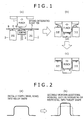
- the hot press forming is performed once as bending illustrated in Fig. 1 .
- the portion A of the blank is in contact with the tools for a long time and undergoes a large temperature reduction (large heat extraction to the tools), and, in contrast, the portions B of the blank are in contact with the tools for a short time and undergo small temperature reduction, each as illustrated in Fig. 1 .
- the formed product may have a difference in magnitude of temperature reduction, thereby have a difference in magnitude of thermal shrinkage, undergo thermal deformation (plastic deformation), and have inferior dimensional accuracy.
- the hot press forming is performed as multistage forming, specifically, press forming is performed multiple times at a temperature or temperatures equal to or higher than the Ms temperature.
- press forming is performed multiple times at a temperature or temperatures equal to or higher than the Ms temperature.
- a subsequent forming is performed still at a high temperature and can easily correct the dimensional accuracy deterioration.
- the repeated forming processes also eliminate or mitigate the temperature nonuniformity and thereby more readily reduce the dimensional accuracy deterioration due to the temperature nonuniformity.
- the method when performing hot press forming in multiple stages as above, can further include a straightening process by shape constraint and advantageously provides better dimensional accuracy, where the dimensional accuracy is an issue in the multistage hot press forming technology.
- the dimensional accuracy deterioration is an issue in a productivity-oriented multistage hot forming process.
- the dimensional accuracy deterioration can be dramatically improved by separating the formed product from the tools at a temperature equal to or lower than the Ms temperature in final hot press forming (including the case where hot press forming is performed once), as is described below.
- the final hot press forming is preferably performed at a finishing temperature of equal to or lower than the Ms temperature.
- the formed product is held in contact with the tools (tool constraint) down to [(Ms temperature) - 150°C] before separation.
- tools tool constraint
- This can give further stably better dimensional accuracy.
- this is useful when the member is formed from a thin blank having a thickness typically of 1.4 mm or less, because such thin blank may undergo large dimensional accuracy deterioration upon multistage forming.
- the hot press forming when performed multiple times, may be performed in the same tools, or in two or more different combinations of tools having different shapes, specifically, in tools having shapes differing from one forming process to another.
- the hot press forming when performed as multistage forming, requires a smaller amount of working per process with respect to the finally necessitated amount of working and enables forming of the blank into a member having a more complicated shape.
- rear side members and other parts are curved three-dimensionally and have different cross-sectional shapes (width and height) in the longitudinal direction. These parts are generally difficult to be formed into final shapes by a single step.
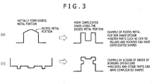
- the multistage forming process (including multiple steps) as illustrated in Fig. 2 enables forming of the parts having such complicated shapes.
- the forming process can be designed as including forming (drawing and/or bending) into a rough shape as in Fig.2(a) in the first step, and additional working (redrawing and/or restriking) into a final shape as indicated by the solid line in Fig. 2(b) in the second step.
- shapes to be worked in the first step and the second step in the multistage forming process may be appropriately designed.
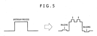
- an excess metal portion may be disposed in an appropriate shape, and the order of working operations may be appropriately set.
- This can provide formed members having significantly complicated shapes as illustrated in Figs. 3(a) and 3(b) .
- the formed members when allowed to have such complicated shapes, can contribute to higher functions (e.g., higher rigidity and/or better crashworthiness) and reduced wall thicknesses of the resulting parts.
- Such structures or parts are exemplified by center pillars and rockers.
- a part when having such a shape or structure, may resist deformation in sectional shape and can have better crashworthiness upon impact on the part (A).
- the part (A) when allowed to have a complicated shape as described above, can have better crashworthiness in itself This can omit or, reduce the thickness of, the reinforcer (C) and contribute to lighter weight and lower cost.
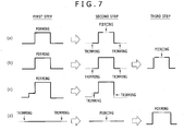
- bulging and/or flanging may be performed in the second or later step, as described below.
- bulging may be performed in the second or later step in the multistage forming process, as illustrated in Fig. 5 .
- This forming allows the steel member to have an additional bulged shape to thereby have a higher function such as higher rigidity and/or better crashworthiness.
- flanging may be performed in the second or later step in the multistage forming process as illustrated in Figs. 6(a) and 6(b) .
- the flanging is exemplified by flange up, flange down, stretch flanging, burring, and shrink flanging. This forming can also allow the steel member to have a higher function such as higher rigidity and/or better crashworthiness.
- piercing or similar process can be performed in a state where the material in the second or later step is soft at a relatively high temperature.
- piercing (punching) and/or peripheral trimming (shearing) can be performed in the second or later step as illustrated in Figs. 7(a), 7(b), and 7(c) .
- Hot peripheral trimming and/or hot piercing (boring) may also be performed before forming, as illustrated in Fig. 7(d) .
- the hot press forming finishing temperature refers to the finishing temperature of final hot press forming and, when hot press forming is performed only once, refers simply to "finishing temperature of hot press forming".
- the hot press forming finishing temperature is not critical and may be equal to or higher than the Ms temperature, or equal to or lower than the Ms temperature.
- the final hot press forming finishing temperature is preferably equal to or lower than the Ms temperature.
- the finishing temperature is more preferably equal to or higher than [(Ms temperature) - 150°C].
- the hot press forming is preferably finished in a temperature range of equal to or lower than the Ms temperature (i.e., at a timing where martensite transformation occurs), where the hot press forming herein refers to final hot press forming in the case of multistage hot press forming. This may provide dramatically better dimensional accuracy both in single-stage forming and multistage forming.
- Embodiments of the hot press forming are exemplified as follows.
- the hot press forming when performed multiple times, may further include a reheating process and/or a temperature-keeping process between two press forming processes.
- the hot press forming is preferably performed without reheating and temperature-keeping so that all the hot press forming processes are performed at start temperatures of equal to or higher than the Ms temperature. This is preferred from the viewpoints of productivity, facility cost, and energy cost.
- the cooling rate from the heating temperature down to [(Ms temperature) - 150°C] is not critical. Typically, the cooling may be performed from the heating temperature down to [(Ms temperature) - 150°C] at an average cooling rate of 2°C/s or more (more preferably 5°C/s or more). Cooling at a cooling rate within such a range contributes to the formation of martensite in a downstream temperature range of equal to or lower than the Ms temperature while approximately preventing the formation of other phases such as ferrite and bainite. This can easily give a high-strength member.
- the cooling rate is not critical in upper limit and may be about 500°C/s or less, and preferably 200°C/s or less in consideration of actual operation. For example, the average cooling rate may be controlled to be from 2°C/s to 10°C/s.
- the cooling rate can be controlled by any combination of conditions typified as follows:
- t n ' 3600 ⁇ 10 ⁇ T n ⁇ 1 + 273 293 ⁇ log t n ⁇ t n ⁇ 1 3600 + 20 ⁇ 20
- t n represents an "n-th" time (in second) when a total cooling time from [(Ms temperature) - 150°C] down to 80°C is divided into 5000 equal parts
- T n represents a temperature (°C) at the n-th time t n , where to is 0 second, and T 0 is [(Ms temperature) - 150°C]
- 10 ⁇ represents the ⁇ -th power of 10, hereinafter the symbols are as defined above.
- tempering parameter ( ⁇ ) as specified by Expression (1) be from 7100 to 8030.
- the tempering parameter ( ⁇ ) is hereinafter also simply referred to as "parameter ⁇ ".
- Expression (1) is derived based on Expression (3).
- Expression (3) is described typically in "Tekko Zairyo" (edited by The Japan Institute of Metals and Materials) and is generally used for specification of the tempering parameter ( ⁇ g ). Based on Expression (3), the hardness of a martensitic steel upon isothermal holding at a temperature T [K] for a time t [hr] can be presumed. Materials having an identical ⁇ g as specified by Expression (3) have an identical hardness as a result of a heat treatment at any temperature for any time. In the case of steel materials, the constant C may be set to 20.
- Expression (3) is expressed on the assumption that the workpiece is isothermally held, as mentioned above.
- a part (formed product) after hot press forming is generally forcedly cooled with a coolant such as tools, air, or water, and cooling thereof is plotted as continuous cooling as illustrated in Fig. 8(a) .
- Expression (3) defined on the assumption of isothermal holding is not applicable to this without modification.
- Expression (3) is therefore modified as follows so as to be applicable to a continuous cooling process of the formed product after hot press forming.
- the modification is performed based on following considerations.
- the cooling curve is divided into micro times at identical intervals and is approximated to a set of micro-time isothermal holding heat treatments, as illustrated in Fig. 8(a) .
- the isothermal holdings at temperatures T1, T2, and T3 for a micro time period ⁇ t as exemplified in Fig. 8(a) are respectively converted into time periods t1', t2', and t3' at a certain base temperature T b as illustrated in Fig. 8(b) .
- the converted time periods are summed up to give a total converted time, and the base expression is applied to assumed isothermal holding at the base temperature T b for the total converted time [t1' + t2' + t3'].
- the cooling curve is approximated to three isothermal holding processes. Specifically, isothermal holding is performed at T1 (K) in a time period ⁇ t from t0 to t1; is performed at T2 (K) in a time period ⁇ t from t1 to t2; and is performed at T3 (K) in a time period ⁇ t from t2 to t3.
- the isothermal holding processes are respectively converted into heat treatments at the base temperature T b (K) for certain time periods t1', t2', and t3'.
- an isothermal holding process at a temperature higher than the base temperature T b is converted into a heat treatment for a longer time period; whereas an isothermal holding process at a temperature lower than the base temperature T b is converted into a heat treatment for a shorter time period.
- the measurement temperature and the measurement time are respectively in “degree in Celsius scale (°C)” and in “second (sec)".
- the temperature and the time in Expression (9) as derived from the base expression are respectively indicated in “Kelvin scale (K)” and in “hour (hr)”.
- the systems of units in Expression (9) are converted respectively into the degree in Celsius scale (°C) and the second (s, sec).
- the base temperature T b can be any temperature, but is herein defined as 20°C.
- the constant C is defined as 20, a value that is generally used in steel materials.
- Expression (11) is modified into an expression in consideration of resistance to temper softening due to Si addition.
- the tempering parameter ( ⁇ g ) in the base expression, Expression (3) is not affected by chemical composition variation.
- silicon (Si) effectively increases the resistance to temper softening, and the tempering parameter becomes apparently smaller with an increasing Si content.
- Si affects the tempering parameter.
- the tempering parameter used herein is calculated while defining the specific temperature [(Ms temperature) - 150°C] as the starting point (T 0 ) where the specific temperature is determined by steel chemical compositions. The tempering parameter is therefore adaptable to variations of chemical compositions within the specific ranges.
- the expression for the Ms temperature lacks the term of Si content, and the term of Si content is added.
- the tempering parameter apparently decreases with an increasing Si content as described above, and a minus (negative) term in consideration of the Si content is added to Expression (11) to give Expression (1).
- the Si content in Expression (1) has a coefficient of 430, where the coefficient has been experimentally determined.
- the tempering parameter may also be determined by determining tempering parameters of micro times one by one, and summing up the determined tempering parameters.
- ⁇ g as specified by the base expression, Expression (3), is defined in order to determine a parameter in a single heat treatment process. If parameters obtained in two or more processes are summed up to give a value, the resulting value may become abnormal (extremely high) and does not meet the parameter in actual operation.
- the cooling herein is performed so that the parameter ⁇ as specified by the above-defined expression be 7100 or more.
- the parameter ⁇ of 7100 corresponds to cooling in the range from [(Ms temperature) - 150°C] down to 80°C at a cooling rate of about 20°C/s (holding time in the tools of 10 seconds).
- the cooling if performed at a parameter ⁇ of less than 7100, may require a long holding time in the tools to cause poor productivity, differing little from conventional methods.
- the parameter ⁇ is preferably 7300 or more, and more preferably 7500 or more.
- the cooling, if performed at a parameter ⁇ of greater than 8030 may fail to allow the steel member to have desired strength-ductility balance. To prevent this, the cooling from [(Ms temperature) - 150°C] down to 80°C may be performed so that the parameter ⁇ is 8030 or less.
- the parameter ⁇ is preferably 7900 or less, and more preferably 7800 or less.
- the cooling herein from [(Ms temperature) - 150°C] down to 80°C has only to be performed so that the parameter ⁇ fall within the specific range, and can be performed by any specific procedure not limited.
- the cooling procedure is exemplified by forced wind cooling and natural cooling.
- the cooling process from [(Ms temperature) - 150°C] down to 80°C may be performed at an identical (constant) cooling rate or at a varying cooling rate according to temperature ranges, as long as the parameter ( ⁇ ) falls within the range.
- the manufacturing method may further include an isothermal holding process and/or a reheating process in the midway of cooling from [(Ms temperature) - 150°C] down to 80°C, as long as the parameter ( ⁇ ) falls within the range.
- the workpiece may, for example, be held in a holding furnace and then cooled by the cooling procedure.
- the workpiece may be cooled from [(Ms temperature) - 150°C] down to 80°C at an average cooling rate of from 5°C/s to 20°C/s.
- the cooling is performed at an average cooling rate of 20°C/s or less.
- the cooling if performed at an average cooling rate of greater than 20°C/s, may require a long holding time in the tools to cause poor productivity, thus differing little from the conventional methods.
- the average cooling rate is more preferably 15°C/s or less.
- the cooling if performed at an excessively low average cooling rate, may fail to allow the steel member to have desired strength-ductility balance.
- the average cooling rate is preferably 5°C/s or more, and more preferably 10°C/s or more.
- Cooling from 80°C down to room temperature may be performed at any cooling rate not critical. Typically, the cooling may be performed by natural cooling.
- the method may further include, after the hot press forming, tempering at a temperature of from 100°C to lower than 600°C.
- the blank also the resulting steel member
- the tempering has a specific chemical composition system as mentioned later and can therefore undergo strength adjustment by the tempering without impairing the strength-ductility balance (TS ⁇ EL balance).
- the tempering is preferably performed at a temperature of 100°C or higher, and more preferably 200°C or higher.
- the tempering if performed at a temperature of 600°C or higher, may fail to allow the steel member to have a high yield stress (YS).
- the tempering when employed, is preferably performed at a temperature of lower than 600°C, and more preferably 300°C or lower.
- the tempering may be performed for a time (holding time at the tempering temperature) of 60 minutes or shorter so as to control costs.
- the blank (steel sheet) for use in the hot press forming will be illustrated.
- the blank for use in the manufacturing method has a chemical composition as follows.
- the carbon content may be 0.15% or more, preferably 0.17% or more, and more preferably 0.20% or more.
- the carbon content may be 0.4% or less, preferably 0.30% or less, and more preferably 0.26% or less in terms of upper limit.
- Silicon (Si) essentially increases the resistance to temper softening and ensures high strengths (to ensure excellent strength-ductility balance). Si also effectively gives better ductility of weld beads after the member is subjected to welding. Si is also effective for ensuring excellent delayed fracture resistance.
- the Si content may be controlled to greater than 1.0%, preferably 1.1% or more, and more preferably 1.2% or more. In contrast, Si, if contained in excess, may cause significant occurrence of internal oxidation (grain boundary oxidation) in the hot rolling process and may cause the subsequent acid wash process to proceed at a significantly low rate, resulting in inferior productivity. To prevent this, the Si content may be controlled to 1.65% or less, preferably 1.45% or less, and more preferably 1.35% or less.
- Aluminum (Al) is used for deoxidation, and, for this purpose, the Al content is preferably 0.01% or more.
- Al if contained in an excessively high content, may cause the Ac 3 temperature to be raised, and this may require a higher heating temperature upon hot press forming, resulting in inferior production efficiency.
- the Al content may be controlled to 0.5% or less, preferably 0.20% or less, more preferably 0.10% or less, and furthermore preferably 0.050% or less.
- Manganese (Mn) is necessary to allow the steel sheet to have better hardenability to thereby give a member having high strengths.
- the Mn content may be controlled to 1% or more, preferably 1.5% or more, more preferably 1.8% or more, and furthermore preferably 2.0% or more.
- Mn if contained in a content of greater than 3.5%, may exhibit saturated effects and cause increased cost.
- the Mn content is controlled herein to 3.5% or less, preferably 3.0% or less, and more preferably 2.8% or less.
- Titanium (Ti) fixes nitrogen (N) as TiN, allows boron (B) as a solute, and thereby effectively ensure hardenability.
- the Ti content is preferably 0.015% or more, and more preferably 0.020% or more.
- Ti if contained in an excessively high content, may cause the material steel sheet (blank) to have strengths higher than necessary and cause shorter lives of cutting-piercing tools, resulting in increased cost.
- the Ti content may be controlled to 0.10% or less, preferably 0.06% or less, and more preferably 0.04% or less.
- Boron (B) allows the steel to have better hardenability and to have high strengths even subjected to slow cooling and is necessary.
- boron may be contained in a content of preferably 0.0003% or more, more preferably 0.0015% or more, and furthermore preferably 0.0020% or more.
- boron if contained in excess, may form boron nitride (BN) in excess to cause toughness deterioration.
- the boron content may be controlled to 0.005% or less, preferably 0.0040% or less, and more preferably 0.0035% or less.
- the steel herein has the chemical composition as above, with the remainder including iron and inevitable impurities such as P, S, N, O, As, Sb, and Sn. Of such inevitable impurities, phosphorus (P) and sulfur (S) contents are controlled each to 0.02% or less.
- Nitrogen (N) if contained in an excessively high content, may cause toughness deterioration after hot forming and/or weldability deterioration. To prevent this, the nitrogen oontent is controlled to 0.01% or less.
- Oxygen (O) causes surface flaws. To prevent this, the oxygen content is preferably controlled to 0.001% or less.
- the steel optionally contains one or more of additional elements as follows within ranges not adversely affecting advantageous effects of the present invention.
- Chromium (Cr) effectively allows the steel sheet to have better hardenability and to surely have excellent oxidation resistance. Specifically, the steel sheet becomes resistant to scale generation upon heating before press forming.
- Cr may be contained in a content of preferably 0.01% or more, and more preferably 0.1% or more. However, Cr, if contained in excess, may have saturated effects and cause increased cost. To prevent this, the Cr content may be controlled in upper limit of preferably 5%, more preferably 3.5% or less, and furthermore preferably 2.5% or less.
- Nickel (Ni) and copper (Cu) effectively allow the steel sheet to have better hardenability and allow the formed product to have better delayed fracture resistance and better oxidation resistance.
- at least one of the elements may be contained in a total content of preferably 0.01% or more, and more preferably 0.1% or more.
- the elements, if contained in excess, may cause surface flaws upon the steel sheet manufacturing. This may result in inferior acid wash properties and inferior productivity.
- the total content of these elements is preferably 0.5% or less, and more preferably 0.3% or less.
- Molybdenum (Mo) effectively allows the steel sheet to have better hardenability.
- the steel sheet when containing this element, is expected to allow the formed product to have reduced hardness variation (to be less nonuniform in hardness).
- the element may be contained in a content of preferably 0.01% or more, and more preferably 0.1% or more.
- Mo if contained in excess, may have saturated effects and cause increased cost.
- the Mo content is controlled in upper limit to preferably 1%, more preferably 0.8% or less, and furthermore preferably 0.5% or less.
- Niobium (Nb) effectively refines the microstructure and contributes to better toughness.
- Nb when contained, may be contained in a content of preferably 0.005% or more, and more preferably 0.01% or more.
- Nb if contained in excess, may cause the material steel sheet (blank) to have excessively high strengths, and this may shorten the lives of tools used in a blanking process and cause increased cost, where the blanking process is the process typically of cutting the blank into a predetermined shape before hot press forming.
- the Nb content may be controlled to preferably 0.1% or less, and more preferably 0.05% or less.
- Such blank having a chemical composition meeting the conditions may be manufactured by any method not limited.
- the blank may for example be manufactured by performing casting, heating, hot rolling, further acid wash, cold rolling, and, as needed, annealing each according to a common procedure.
- the resulting hot-rolled steel sheet or cold-rolled steel sheet may be further subjected to coating (e.g., zinc-containing coating).
- coating e.g., zinc-containing coating
- coated steel sheets e.g., galvanized steel sheets
- hot-dip galvannealed steel sheets that are obtained by further alloying the coated steel sheets.
- the hot press formed steel member obtained by the method according to the present invention has a chemical composition identical to that of the blank (steel sheet) used.
- the steel member is not limited in microstructure.
- the microstructure of the steel member is exemplified by one including martensite phase alone; and one including martensite as a matrix and further including retained austenite (retained ⁇ ) in a content of 2 percent by volume or more, preferably 3 percent by volume or more, and more preferably 5 percent by volume or more, relative to the entire microstructure.
- the steel member containing retained ⁇ in a content of 2 percent by volume or more may excel in tensile elongation (ductility), crashworthiness, and delayed fracture resistance, as described above.
- the steel member may include, as the steel microstructure, the retained ⁇ with the remainder approximately including low-temperature transformation phases such as martensite, tempered martensite, bainite, and bainitic ferrite.
- low-temperature transformation phases such as martensite, tempered martensite, bainite, and bainitic ferrite.
- approximately refers to that the steel member may include ferrite and other transformation phases that are formed at a temperature equal to or higher than the Ms temperature, as phases that are inevitably formed in the manufacturing process.
- the resulting steel member may be subjected to cutting (machining) such as trimming and/or piecing to give, for example, a steel automotive part.
- the steel member may be used as a steel automotive part as intact or with working (processing) as mentioned above.
- the steel automotive part is exemplified by impact bars, bumpers, reinforcements, and center pillars.
- Steel sheets having chemical compositions given in Table 1 were prepared as blanks.
- the steel sheets dimensionally had a thickness of 1.4 mm, a width of 190.5 mm, and a length of 400 mm.
- the steel sheets were subjected to hot press forming as press forming according to the procedure illustrated in Fig. 9 .
- the hot press forming is hereinafter also simply referred to as "press forming” or "pressing”.
- Table 1 also indicates Ac 3 temperatures and Ms temperatures as calculated by the expressions. The calculations according to the expressions for the Ac 3 temperatures and Ms temperatures were performed while defining the content of an element not contained as zero.
- Each sample in Experimental Example 1 was manufactured under conditions as follows. Specifically, the blank was heated at 900°C (heating temperature) for 6 minutes and subjected to hot press forming at a start temperature of from 800°C to 700°C. During the process of heating the steel sheet (blank) up to the heating temperature, the steel sheet was heated in the range from 100°C up to the heating temperature at an average rate of temperature rise of about 10°C/s. The steel sheet was cooled from the heating temperature down to [(Ms temperature) - 150°C] at an average cooling rate of 10 to 30°C/s.
- the hot press forming was performed as press forming (bending (form) using a leading pad) as illustrated in Fig. 1 using a pressing machine (400-ton mechanical press) to give a hat channel steel member illustrated in Fig. 10 .
- the leading pad employed, as a pressure source, a spring having force of about 1 ton.
- Fig. 1 illustrates the forming process.
- Fig. 1 illustrates a punch 1, a die 2, a leading pad 3, a steel sheet (blank) 4, and a pin (spring-integrated float pin) 5.
- the spring-integrated pins 5 are placed on the tools (die 2 and leading pad 3), and the blank 4 retrieved from the heating furnace is once placed on the pins 5. This is performed so as to minimize the contact between the blank 4 and the tools (die 2 and leading pad 3) before press forming start.
- Fig. 1(b) illustrates a state during the forming, i.e. a state during depressing of the punch 1.
- Fig. 1(c) illustrates a state where the punch 1 is depressed down and reaches the bottom dead center (lower limit position).
- Test No. 16 was subjected to press forming three times, and Test Nos. 17 and 18 were subjected to press forming four times.
- Test Nos. 1 to 7 and 10 to 51 in Tables 2 and 3 were held in the tools for a time (tool contact time, bottom dead center holding time) of from about 0.8 to about 7 seconds as in Fig. 9 .
- Test Nos. 3, 4, and 19 in Table 2 were held in the tools for a time of about 7 seconds.
- thermocouples were embedded at positions corresponding to the center parts of the top and the vertical wall of the resulting steel member to measure the temperature history of the steel sheet upon steel member manufacturing. The temperatures measured at the two positions were approximately identical
- a cooling time from [(Ms temperature) - 150°C] down to 80°C was read out from the measured temperature history to calculate an average cooling rate and a tempering parameter ( ⁇ ) as indicated in Tables 2 and 3. Specifically, the tempering parameter was calculated while defining t 0 of 0 (second) and T 0 of [Ms-150°C] as starting points, and setting the measured cooling history from [(Ms temperature) - 150°C] down to 80°C and the Si content.
- a final tool release temperature indicated in Tables 2 and 3 was determined based on the temperatures indicated by the thermocouples and the positions of the tools at that time. In this experimental example, the final tool release temperature corresponds to the final hot press forming finishing temperature.
- the thus-obtained steel members (formed members) were each subjected to a tensile test and productivity evaluation by methods as follows.
- the prepared steel members each included a martensite single phase as a microstructure.
- a JIS No. 5 test specimen was cut out as a tensile test specimen, as illustrated in Fig. 12 .
- the test specimen was subjected to the tensile test by the method prescribed in JIS Z 2241 using AG-IS 250kN Autograph Tensile Tester (Shimadzu Corporation) to measure a yield strength (YS), a tensile strength (TS), and an elongation (EL).
- the test was performed at a strain rate of 10 mm/min. Based on the data, the product (TS ⁇ EL; MPa • %) of the tensile strength TS and the elongation EL was determined.
- the productivity was evaluated by the length of the in-tool holding time, where the in-tool holding is a rate-determining step in the hot press forming process.
- a sample underwent in-tool holding for a time of 10 seconds or longer was evaluated as being equivalent to conventional techniques and as having poor productivity ( ⁇ ); whereas a sample underwent in-tool holding for a time of shorter than 10 seconds was evaluated as having good productivity ( ⁇ ).
- Test Nos. 1 to 4 each had an insufficient Si content and failed to have excellent strength-ductility balance.
- the data of Test Nos. 2 and 3 demonstrate that the samples, when having an insufficient Si content, fail to have sufficiently high strength-ductility balance even at different average cooling rates in the range from [(Ms temperature) - 150°C] down to 80°C.
- Test No. 4 had a parameter ⁇ greater than the specific range and had remarkably poor strength-ductility balance.
- Test Nos. 5 to 7 underwent cooling from [(Ms temperature) - 150°C] down to 80°C performed so that the parameter ⁇ is greater than the specific range and had poor strength-ductility balance.
- Test Nos. 8 and 9 underwent cooling from [(Ms temperature) - 150°C] down to 80°C performed so that the parameter ⁇ is less than the specific range and gave a steel member with poor productivity.
- Test Nos. 41, 42, 47, and 48 underwent cooling from [(Ms temperature) - 150°C] down to 80°C performed so that the parameter ⁇ is greater than the specific range and had poor strength-ductility balance.
- Test Nos. 10 to 40,43 to 46, and 49 to 51 employed steel sheets having chemical compositions as specified in the present invention, underwent the method for manufacturing steel member as specified in the present invention, and gave steel members that had high strengths and excellent strength-ductility balance with good productivity.
- Test Nos. 10 to 14 employed an identical blank, but underwent cooling from [(Ms temperature) - 150°C] down to 80°C at different parameters ⁇ .
- the resulting steel members each had good strength-ductility balance.
- Test Nos. 15 to 18 employed an identical blank, but underwent press forming in different numbers of operations at different final tool release temperatures. A comparison among data of these tests demonstrates that the resulting steel member can have productivity and strength-ductility balance both at high levels by performing multistage forming at a low final tool release temperature.
- each sample was prepared as a small-sized flat sheet having a thickness of 1.4 mm, a width of 180 mm, and a length of 50 mm, subjected to a heat treatment using electric heating equipment, and evaluated.
- the steel sheet of Blank “A” in Table 1 was heated up to a heating temperature of 900°C.
- the steel sheet was heated from 100°C up to the heating temperature at different average rates of temperature rise as given in Table 4 below.
- the power supply was stopped, the sample was naturally cooled down to 800°C, further cooled so that the average cooling rate from the heating temperature (900°C) down to [(Ms temperature) - 150°C] is about 10°C/s, further cooled from [(Ms temperature) - 150°C] down to 80°C so that the tempering parameter ( ⁇ ) is a value given in Table 4, and thereby yielded a heat-treated sample.
- Other conditions than those mentioned above were as with Test No. 15 in Table 2.
- Each test was performed at a heating temperature of 900°C and a cooling start temperature (corresponding to forming start temperature) of 800°C. * Each test was performed at an average cooling rate of about 10°C/s in the range from the heating temperature down to [(Ms temperature) - 150°C].
- the steel sheet can have higher TS ⁇ EL balance by heating the steel sheet up to the heating temperature at a higher average rate of temperature rise in the temperature range from 100°C up to the heating temperature.
- the heating is preferably performed at an average rate of temperature rise of 50°C/s or more so as to allow the steel sheet to have good TS ⁇ EL balance of 14000 MPa ⁇ % or more.
- Steel members were prepared by the procedure of Test No. 16 (final tool release temperature: 380°C) in Table 2 in Experimental Example 1, except that steel members prepared by hot press forming were further subjected to tempering as described below.
- the tempering was performed so that the steel members after hot press forming were each heated up to a tempering temperature given in Table 5 at an average rate of temperature rise of 40°C/s, and water-cooled without being held at the tempering temperature.
- Table 5 demonstrates as follows.
- a comparison of Test No. 58 with Test Nos. 59 to 62 demonstrates that the samples, even when further subjected to tempering, can be controlled in strength without having inferior TS ⁇ EL balance.
- the data of Test No. 63 demonstrate that tempering is preferably performed at a tempering temperature of lower than 600°C in terms of upper limit so as to provide a desired yield strength (800 MPa or more).
Description
- The present invention relates to methods for manufacturing hot press formed steel members. Specifically, the present invention relates to a method for manufacturing a hot press formed steel member that has high strengths and excellent balance between strength and ductility (strength-ductility balance).
- Materials for steel automotive parts are designed to have higher strengths so as to achieve both crashworthiness and reduction in weight. Independently, the parts upon manufacturing require good workability of material steel sheets. Assume that such high-strength steel sheets, in particular steel sheets having a tensile strength of 980 MPa or more, are subjected to cold working (e.g., cold press forming). Disadvantageously, however, this requires a higher press forming load or causes remarkably low dimensional accuracy.
- As a possible solution to the disadvantage, there is a hot press forming technique. The hot press forming is also called hot pressing or hot stamping. In the hot press forming, a material steel sheet is subjected to press forming while being heated so as to perform forming and achieve higher strengths simultaneously. In this technique, the steel sheet at a high temperature (e.g., in the austenite single phase region) is formed or shaped with tools (punch and die), held and cooled at the (forming) bottom dead center to extract heat from the steel sheet to the tools to thereby rapidly cool the steel sheet. Thus, the material steel sheet is quenched. The forming technique, when performed, can give a formed product having good dimensional accuracy and high strengths. The technique can be performed with a lower forming load as compared with cold forming of parts having strengths at a similar same level.
- However, the technique requires holding at the bottom dead center for ten and several seconds so as to extract heat into the tools; and during this period, forming of another part is impossible. Unfortunately, one steel member therefore occupies the pressing machine for a long time, and this results in poor productivity.
- In addition, the hot press forming requires cooling at a cooling rate of 30°C/second or more. Thus, forming as well as transfer has to be performed within a short time of ten and several seconds; the press forming can be performed approximately only once; and there is a limit to the shape capable of forming by one press forming. Disadvantageously, the technique therefore fails to manufacture parts having complicated shapes. Further disadvantageously, the resulting steel member obtained after the working has high strengths and poor ductility, is not expected to have high shock absorption upon collision, and is limited in uses to which the steel member is applicable.
- To solve these disadvantages, investigations have been made to improve the productivity and/or to improve the degree of freedom of forming in hot press forming techniques.
- Typically, Patent literature (PTL) 1 discloses that the productivity could be improved by holding a workpiece at the bottom dead center for a shorter time, separating the workpiece from the tools at a higher temperature, and subjecting the workpiece to a subsequent step. This technique, however, requires rapid cooling (at a rate of 150°C/s in working examples) after forming, thereby requires a special facility design, and is probably poorly versatile, although the technique provides a shorter holding time in the tools. In addition, the manufacturing method specified in
PTL 1 performs forming for a short time of ten and several seconds as in conventional techniques, is difficult to perform multistage press forming, and fails to process the workpiece into a complicated shape. -
PTL 2 discloses a hot press forming method. In this method, cooling water is injected from tools during press forming so as to shorten the holding time at the bottom dead center and to achieve both high strengths and satisfactory productivity. The method, however, requires complicated production facilities to inject the cooling water from the tools and is not versatile. -
PTL 3 to 5 each proposes hot press forming methods. In the method disclosed inPTL 3, a steel sheet heated to 1000°C or lower is subjected to multistage press forming of two to five stages (steps) in a temperature range of 600°C or higher and then cooled at a cooling rate of 10°C/second or more. In the multistage press forming, press forming per stage is performed within 3 seconds, and a subsequent press forming is performed within 4 seconds. In the method disclosed inPTL 4, a steel sheet is heated to a temperature range from the AC3 temperature to the melting point, is partially supported by a punch provided in tools, is subjected to forming at a start temperature higher than a temperature at which all of ferrite, pearlite, bainite, and martensite transformations occur, and is rapidly cooled after the forming. In the method disclosed inPTL 5, press forming is performed so that a formed product is released from press forming tools within 5 seconds after the press forming tools reach the bottom dead center and cooled at a cooling rate of 30°C/s or more so as to allow the formed part to have a hardness HV of 400 or more. - However, further improvements such as adjustment of chemical compositions are probably required so as to surely provide excellent strength-ductility balance.
-
- PTL 1: Japanese Unexamined Patent Application Publication (
JP-A) No. 2011-218436 - PTL 2:
JP-A No. 2002-282951 - PTL 3:
JP-A No. 2005-152969 - PTL 4:
JP-A No. 2009-82992 - PTL 5:
JP-A No. 2005-288528 -
EP 2 546 375 A1 - The present invention has been made under these circumstances, and an object of the present invention is to establish and provide a technique for manufacturing a steel member by hot press forming inexpensively and efficiently with high degree of freedom in the shape to be formed, where the steel member has high strengths and excellent strength-ductility balance and offers good deformation properties (crashworthiness) upon collision collapse.
- As used herein the term "high strengths" in the steel member according to the present invention refers to having a yield strength of 800 MPa or more (preferably 850 MPa or more, and more preferably 900 MPa or more) and a tensile strength of 980 MPa or more (preferably 1270 MPa or more, and more preferably 1470 MPa or more). The yield strength and tensile strength herein are determined by methods described in after-mentioned experimental examples. Also as used herein the term "excellent strength-ductility balance" in the steel member according to the present invention refers to that the steel member has a product (TS × EL) of tensile strength TS and elongation EL of 13550 MPa•% or more (preferably 13600 MPa•% or more, more preferably 13700 MPa•% or more, furthermore preferably 13800 MPa•% or more, and particularly preferably 14000 MPa•% or more), where the product TS × EL is determined by a method described in the experimental examples.
- The present invention achieves the object and provides a method for manufacturing a hot press formed steel member. The method includes heating a steel sheet and subjecting the steel sheet to at least one time of hot press forming. The steel sheet consists of, as a chemical composition in mass percent (hereinafter the same for chemical composition),
- C in a content of 0.15% to 0.4%;
- Si in a content of greater than 1.0% to 1.65%;
- A1 in a content of 0.5% or less (excluding 0%);
- Mn in a content of 1% to 3.5%;
- Ti in a content of 0.10% or less (excluding 0%); and
- B in a content of 0.005% or less (excluding 0%),
- (a) Cr in a content of 5% or less (excluding 0%);
- (b) at least one element selected from the group consisting of Ni and Cu in a total content of 0.5% or less (excluding 0%);
- (c) Mo in a content of 1% or less (excluding 0%);
- (d) Nb in a content of 0.1% or less (excluding 0%);
- (e) P in a content of 0.02% or less;
- (f) S in a content of 0.02% or less; and
- (g) N in a content of 0.01% or less,
- The cooling from [(Ms temperature) - 150°C] down to 80°C may be performed at an average cooling rate of 5°C/s to 20°C/s.
- The finishing temperature of final hot press forming in the at least one time of the hot press forming may be equal to or lower than the Ms temperature.
- The step of heating the steel sheet up to the heating temperature is preferably performed at an average rate of temperature rise of 5°C/s or more in the temperature range from 100°C up to the heating temperature.
- After the hot press forming, tempering may be performed at a temperature of from 100°C to lower than 600°C.
- The present invention also includes a method for manufacturing a steel automotive part, wherein the method comprises a step of manufacturing a hot press formed steel member by the method for manufacturing a hot press formed steel member according to the present invention, and further comprises a step of working the hot press formed steel member.
- The method for manufacturing a hot press formed steel member according to the present invention can give a steel member by hot press forming, where the steel member has high strengths and excellent strength-ductility balance, offers good deformation properties (crashworthiness) upon crushing by collision, and is useful as or for high-strength steel parts for automobiles. Unlike conventional hot press forming techniques, the manufacturing method does not require long-term holding at the bottom dead center, can manufacture steel members efficiently, can perform hot press forming multiple times, and has a high degree of freedom in shape to be formed.
-
- [
Fig. 1] Figs. 1(a), 1(b), and 1(c) are explanatory drawings illustrating respectively of before, in the midway, and at the forming bottom dead center of hot press forming in the experimental examples; - [
Fig. 2] Fig. 2 is a schematic explanatory drawing illustrating a multistage forming process; - [
Fig. 3] Fig. 3 is an explanatory drawing illustrating multistage forming processes according to embodiments; - [
Fig. 4] Fig. 4 is a cross-sectional view of a steel member including a reinforcer; - [
Fig. 5] Fig. 5 is a schematic explanatory drawing illustrating bulging in a multistage forming process according to an embodiment; - [
Fig. 6] Fig. 6 is a schematic explanatory drawing illustrating flanging in a multistage forming process according to an embodiment; - [
Fig. 7] Fig. 7 is a schematic explanatory drawing illustrating piercing and (peripheral) trimming in multistage forming processes according to embodiments; - [
Fig. 8] Fig. 8 is an explanatory drawing illustrating how to derive Expression (1) as specified in the present invention; - [
Fig. 9] Fig. 9 is a process chart illustrating hot press forming in the experimental examples; - [
Fig. 10] Fig. 10 is a schematic perspective view illustrating the shape of a steel member obtained in the experimental examples; - [
Fig. 11] Fig. 11 is a schematic perspective view illustrating a position where thermocouple are embedded to measure the temperature of a steel sheet in the experimental examples; and - [
Fig. 12] Fig. 12 is a schematic perspective view illustrating a position where a test specimen for tensile test is sampled from a steel member in the experimental examples. - The present inventors made intensive investigations to provide a steel member having the properties. As a result, they have found a specific method for manufacturing a steel member using a steel sheet having a specific chemical composition by heating the steel sheet and subjecting the heated steel sheet to hot press forming at least one time. The method is performed while meeting the conditions (i) to (iii). Specifically, (i) the heating temperature is controlled to equal to or higher than the Ac3 transformation temperature. In addition, (ii) the hot press forming is started at a temperature in the range from the heating temperature down to the Ms temperature. Further, (iii) cooling from [(Ms temperature) - 150°C] down to 80°C is performed so that a tempering parameter (λ) as specified by Expression (1) is from 7100 to 8030. The present invention has been made based on these findings.
- Reasons why manufacturing conditions including the conditions (i) to (iii) are specified in the present invention will be described in detail below.
- Heating up to a temperature equal to or higher than the Ac3 transformation temperature allows the steel member to have a martensite single phase as its microstructure and to have predetermined strengths. The "Ac3 transformation temperature" refers to an austenite transformation temperature and is hereinafter also simply referred to as "Ac3 temperature". The heating, if performed at a temperature lower than the Ac3 transformation temperature, causes ferrite and other phases to remain and to act as nuclei during hot forming and thereby allows ferrite to grow easily. This probably causes the steel member to hardly have high strengths even when the cooling rate after heating is controlled.
- The heating temperature is preferably equal to or higher than [(Ac3 temperature) + 10°C]. The heating, if performed at an excessively high temperature, may cause the microstructure constituting the steel member to coarsen and may cause the steel member to have inferior strength-ductility balance. To prevent this, the heating temperature may be controlled in upper limit to preferably equal to or lower than about [(Ac3 temperature) + 180°C], and more preferably equal to or lower than about [(Ac3 temperature) + 150°C].
- The holding at the heating temperature may be performed for a time (heating holding time) of preferably 15 minutes or shorter, and more preferably 5 minutes or shorter. This is preferred typically for restraining austenite grain growth. The holding does not have to be performed, namely, the heating-holding time may be zero, as long as the heating temperature falls within the specific range.
- The heating may be performed in an atmosphere as selected from oxidizing atmospheres, reducing atmospheres, and non-oxidizing atmospheres. Specifically, the atmosphere is exemplified by air atmosphere, combustion gas atmosphere, and nitrogen gas atmosphere.
- In the step of heating the steel sheet up to the heating temperature, the heating is preferably performed at an average rate of temperature rise of 5°C/second or more in the temperature range from 100°C up to the heating temperature. The heating at such a high rate of temperature rise may refine (reduced the grain size of) the phase (prior austenite) to contribute to still better strength-ductility balance. The average rate of temperature rise is more preferably 50°C/s or more, and furthermore preferably 100°C/s or more. The average rate of temperature rise is not critical in upper limit for better strength-ductility balance, but is preferably about 500°C/s or less in consideration typically of the heating equipment size and the size of the part to be manufactured.
- The hot press forming, when started at a temperature in the range from the heating temperature down to the Ms temperature, enables easy working and sufficiently reduces the forming load of press forming. The hot press forming, if started at a temperature lower than the Ms temperature, is to be performed on a high-strength martensitic steel Disadvantageously, this causes over loading of press forming because a pressing machine for hot press forming is generally not so powerful, or causes increased risk of delayed fracture due to high residual stress. To prevent this, the hot press forming start temperature is controlled to be equal to or higher than the Ms temperature. The hot press forming start temperature is preferably equal to or higher than [(Ms temperature) + 30°C], and more preferably equal to or higher than [(Ms temperature) + 50°C].
- In the present invention, the term "start" of the hot press forming refers to a timing at which part of the steel sheet (blank) first comes in contact with at least part of the tools in first forming. The term "finish" of the hot press forming refers to a timing at which the entire part of the formed product is separated from the tools in final forming.
- In the present invention, a starting temperature (in other words, the blank temperature at the timing when part of the blank first comes into contact with at least part of the tools in the first forming) of the hot press forming is specified, while there is no limitation on a finishing temperature (in other words, the blank (steel member) temperature at the timing when the entire formed product (steel member) is separated from the tools in the final forming) of the hot press forming. A preferred finishing temperature of the hot press forming will be described in detail below.
- The Ac3 temperature and the Ms temperature are respectively calculated according to Expressions (a) and (b) described in "The Physical Metallurgy of Steels", William C. Leslie (Maruzen Co., Ltd., May 31, 1985, p. 273). In the expressions, an element indicated in the brackets represents the content (in mass percent) of the element, and the calculation may be performed while defining the content of an element not contained in the steel sheet as 0 percent by mass. Expressions (a) and (b) are expressed as follows:


- The hot press forming may be performed once or multiple times. The hot press forming, when performed multiple times, can give a member having a complicated shape and can provide better dimensional accuracy. A mechanism for providing better dimensional accuracy is as follows.
- During the press forming process, different portions of the blank are in contact with the tools for different durations, and this may cause temperature difference (nonuniformity) in the formed product. Typically, assume that the hot press forming is performed once as bending illustrated in
Fig. 1 . In this case, the portion A of the blank is in contact with the tools for a long time and undergoes a large temperature reduction (large heat extraction to the tools), and, in contrast, the portions B of the blank are in contact with the tools for a short time and undergo small temperature reduction, each as illustrated inFig. 1 . Thus, the formed product may have a difference in magnitude of temperature reduction, thereby have a difference in magnitude of thermal shrinkage, undergo thermal deformation (plastic deformation), and have inferior dimensional accuracy. - In an embodiment, the hot press forming is performed as multistage forming, specifically, press forming is performed multiple times at a temperature or temperatures equal to or higher than the Ms temperature. In this embodiment, even when dimensional accuracy deterioration occurs in a previous forming, a subsequent forming is performed still at a high temperature and can easily correct the dimensional accuracy deterioration. In addition, the repeated forming processes also eliminate or mitigate the temperature nonuniformity and thereby more readily reduce the dimensional accuracy deterioration due to the temperature nonuniformity.
- In addition, the method, when performing hot press forming in multiple stages as above, can further include a straightening process by shape constraint and advantageously provides better dimensional accuracy, where the dimensional accuracy is an issue in the multistage hot press forming technology. The dimensional accuracy deterioration is an issue in a productivity-oriented multistage hot forming process. The dimensional accuracy deterioration, however, can be dramatically improved by separating the formed product from the tools at a temperature equal to or lower than the Ms temperature in final hot press forming (including the case where hot press forming is performed once), as is described below. Specifically, the final hot press forming is preferably performed at a finishing temperature of equal to or lower than the Ms temperature. In a more preferred embodiment, the formed product is held in contact with the tools (tool constraint) down to [(Ms temperature) - 150°C] before separation. This can give further stably better dimensional accuracy. In particular, this is useful when the member is formed from a thin blank having a thickness typically of 1.4 mm or less, because such thin blank may undergo large dimensional accuracy deterioration upon multistage forming.
- The hot press forming, when performed multiple times, may be performed in the same tools, or in two or more different combinations of tools having different shapes, specifically, in tools having shapes differing from one forming process to another.
- The hot press forming, when performed as multistage forming, requires a smaller amount of working per process with respect to the finally necessitated amount of working and enables forming of the blank into a member having a more complicated shape.
- For example, rear side members and other parts are curved three-dimensionally and have different cross-sectional shapes (width and height) in the longitudinal direction. These parts are generally difficult to be formed into final shapes by a single step. However, the multistage forming process (including multiple steps) as illustrated in
Fig. 2 enables forming of the parts having such complicated shapes. Specifically, the forming process can be designed as including forming (drawing and/or bending) into a rough shape as inFig.2(a) in the first step, and additional working (redrawing and/or restriking) into a final shape as indicated by the solid line inFig. 2(b) in the second step. - In addition, shapes to be worked in the first step and the second step in the multistage forming process may be appropriately designed. Typically, an excess metal portion may be disposed in an appropriate shape, and the order of working operations may be appropriately set. This can provide formed members having significantly complicated shapes as illustrated in
Figs. 3(a) and 3(b) . The formed members, when allowed to have such complicated shapes, can contribute to higher functions (e.g., higher rigidity and/or better crashworthiness) and reduced wall thicknesses of the resulting parts. - Actual automotive body structures often employ a structure including a part (A), and a reinforcer (C) inside of the part (A), as illustrated in
Fig. 4 (cross-sectional view). Such structures or parts are exemplified by center pillars and rockers. A part, when having such a shape or structure, may resist deformation in sectional shape and can have better crashworthiness upon impact on the part (A). However, the part (A), when allowed to have a complicated shape as described above, can have better crashworthiness in itself This can omit or, reduce the thickness of, the reinforcer (C) and contribute to lighter weight and lower cost. - In embodiments of the multistage forming, bulging and/or flanging may be performed in the second or later step, as described below. Typically, bulging may be performed in the second or later step in the multistage forming process, as illustrated in
Fig. 5 . This forming allows the steel member to have an additional bulged shape to thereby have a higher function such as higher rigidity and/or better crashworthiness. Also typically, flanging may be performed in the second or later step in the multistage forming process as illustrated inFigs. 6(a) and 6(b) . The flanging is exemplified by flange up, flange down, stretch flanging, burring, and shrink flanging. This forming can also allow the steel member to have a higher function such as higher rigidity and/or better crashworthiness. - In another embodiment of the multistage forming, piercing or similar process can be performed in a state where the material in the second or later step is soft at a relatively high temperature. Typically, piercing (punching) and/or peripheral trimming (shearing) can be performed in the second or later step as illustrated in
Figs. 7(a), 7(b), and 7(c) . This allows piercing and/or trimming to be performed as a process in press forming and enables cost reduction, where such piercing and/or trimming has been performed typically by laser working as an extra step in conventional forming processes including only one step of holding at the bottom dead center. Hot peripheral trimming and/or hot piercing (boring) may also be performed before forming, as illustrated inFig. 7(d) . - The "hot press forming finishing temperature" refers to the finishing temperature of final hot press forming and, when hot press forming is performed only once, refers simply to "finishing temperature of hot press forming". The hot press forming finishing temperature is not critical and may be equal to or higher than the Ms temperature, or equal to or lower than the Ms temperature.
- For better dimensional accuracy, the final hot press forming finishing temperature is preferably equal to or lower than the Ms temperature. In this case, the finishing temperature is more preferably equal to or higher than [(Ms temperature) - 150°C]. Specifically, the hot press forming is preferably finished in a temperature range of equal to or lower than the Ms temperature (i.e., at a timing where martensite transformation occurs), where the hot press forming herein refers to final hot press forming in the case of multistage hot press forming. This may provide dramatically better dimensional accuracy both in single-stage forming and multistage forming.
- Start Temperatures and Finishing Temperatures in Respective Embodiments of Hot Press Forming
- Embodiments of the hot press forming are exemplified as follows.
-
- (I-1) The hot press forming is performed at a start temperature of from the heating temperature down to the Ms temperature and at a finishing temperature of equal to or higher than the Ms temperature.
- (I-2) The hot press forming is performed at a start temperature of from the heating temperature down to the Ms temperature and at a finishing temperature of equal to or lower than the Ms temperature.
-
- (II-1) The first hot press forming is performed at a start temperature of from the heating temperature down to the Ms temperature, and the final hot press forming is performed at a finishing temperature of equal to or higher than the Ms temperature.
- (II-2) The first hot press forming is performed at a start temperature of from the heating temperature down to the Ms temperature, and the final hot press forming is performed at a finishing temperature of equal to or lower than the Ms temperature.
- The hot press forming, when performed multiple times, may further include a reheating process and/or a temperature-keeping process between two press forming processes. However, the hot press forming is preferably performed without reheating and temperature-keeping so that all the hot press forming processes are performed at start temperatures of equal to or higher than the Ms temperature. This is preferred from the viewpoints of productivity, facility cost, and energy cost.
- The cooling rate from the heating temperature down to [(Ms temperature) - 150°C] is not critical. Typically, the cooling may be performed from the heating temperature down to [(Ms temperature) - 150°C] at an average cooling rate of 2°C/s or more (more preferably 5°C/s or more). Cooling at a cooling rate within such a range contributes to the formation of martensite in a downstream temperature range of equal to or lower than the Ms temperature while approximately preventing the formation of other phases such as ferrite and bainite. This can easily give a high-strength member. The cooling rate is not critical in upper limit and may be about 500°C/s or less, and preferably 200°C/s or less in consideration of actual operation. For example, the average cooling rate may be controlled to be from 2°C/s to 10°C/s.
- The cooling rate can be controlled by any combination of conditions typified as follows:
- the time from the retrieval of the blank from the heating furnace to the press forming start (rate upon cooling typically by transfer);
- the total contact time with the press forming tools upon hot press forming, where the total contact time is given by multiplying the contact time per one process by the number of forming processes;
- the cooling conditions (e.g., natural cooling or forced wind cooling) between adjacent two forming processes when press forming is performed multiple times; and
- the cooling conditions (e.g., natural cooling or forced wind cooling) after the finish of press forming (after tool release). In particular, it is effective to determine a longer contact time with the press forming tools so as to increase the cooling rate in a temperature of equal to or higher than [(Ms temperature) - 150°C]. These cooling conditions can be previously estimated typically by simulation.
- (iii) Cooling from [(Ms temperature) - 150°C] down to 80°C is performed so that a tempering parameter (λ) as specified by Expression (1) be from 7100 to 8030, where Expression (1) is expressed as follows:
[Math. 3]
[Math. 4]
- According to the present invention, cooling from [(Ms temperature) - 150°C] down to 80°C is controlled so that a tempering parameter (λ) as specified by Expression (1) be from 7100 to 8030. The tempering parameter (λ) is hereinafter also simply referred to as "parameter λ".
- How to derive the parameter λ will be initially described.
- Expression (1) is derived based on Expression (3). Expression (3) is described typically in "Tekko Zairyo" (edited by The Japan Institute of Metals and Materials) and is generally used for specification of the tempering parameter (λg). Based on Expression (3), the hardness of a martensitic steel upon isothermal holding at a temperature T [K] for a time t [hr] can be presumed. Materials having an identical λg as specified by Expression (3) have an identical hardness as a result of a heat treatment at any temperature for any time. In the case of steel materials, the constant C may be set to 20. Expression (3) is expressed as follows:

- Expression (3) is expressed on the assumption that the workpiece is isothermally held, as mentioned above. In contrast, a part (formed product) after hot press forming is generally forcedly cooled with a coolant such as tools, air, or water, and cooling thereof is plotted as continuous cooling as illustrated in
Fig. 8(a) . Expression (3) defined on the assumption of isothermal holding is not applicable to this without modification. - Expression (3) is therefore modified as follows so as to be applicable to a continuous cooling process of the formed product after hot press forming.
- The modification (improvement) is performed based on following considerations. Initially, the cooling curve is divided into micro times at identical intervals and is approximated to a set of micro-time isothermal holding heat treatments, as illustrated in
Fig. 8(a) . The isothermal holdings at temperatures T1, T2, and T3 for a micro time period Δt as exemplified inFig. 8(a) are respectively converted into time periods t1', t2', and t3' at a certain base temperature Tb as illustrated inFig. 8(b) . The converted time periods are summed up to give a total converted time, and the base expression is applied to assumed isothermal holding at the base temperature Tb for the total converted time [t1' + t2' + t3']. - Next, how to specifically derive the modified expression will be described with reference to
Figs. 8(a) and 8(b) as an embodiment. - As illustrated in
Fig. 8(a) , the cooling curve is approximated to three isothermal holding processes. Specifically, isothermal holding is performed at T1 (K) in a time period Δt from t0 to t1; is performed at T2 (K) in a time period Δt from t1 to t2; and is performed at T3 (K) in a time period Δt from t2 to t3. The isothermal holding processes are respectively converted into heat treatments at the base temperature Tb (K) for certain time periods t1', t2', and t3'. Specifically, an isothermal holding process at a temperature higher than the base temperature Tb is converted into a heat treatment for a longer time period; whereas an isothermal holding process at a temperature lower than the base temperature Tb is converted into a heat treatment for a shorter time period. - Typically, when isothermal holding is performed at T1 (K) in the time period Δt from t0 to t1, this isothermal holding process may be converted into a heat treatment at the base temperature Tb (K) for a time period t1' as specified by and derived from Expressions (4) to (6):

[Math. 5]
[Math. 6]
- The time periods t2' and t3' are determined in a similar manner, and the converted time periods t1', t2', and t3' are summed up, and the total sum is substituted into Expression (3) to give Expression (7):

- Expression (7) and Expression (6) are generalized to respectively give Expression (8) and Expression (9):

[Math. 7]
- In this connection, the measurement temperature and the measurement time are respectively in "degree in Celsius scale (°C)" and in "second (sec)". In contrast, the temperature and the time in Expression (9) as derived from the base expression are respectively indicated in "Kelvin scale (K)" and in "hour (hr)". The systems of units in Expression (9) are converted respectively into the degree in Celsius scale (°C) and the second (s, sec). The base temperature Tb can be any temperature, but is herein defined as 20°C. The constant C is defined as 20, a value that is generally used in steel materials. The systems of units are converted, and the base temperature Tb of 20°C and the constant C of 20 are substituted into Expression (9) to give Expression (10):
[Math. 8]
- In addition, calculation according to Expression (8) is performed by dividing the entire cooling process into 5000 parts. The number "n" therefore takes a value of from 1 to 5000. The temperature specified by [(Ms temperature) - 150°C] is defined as a starting point. Accordingly, t0 is 0 (sec), T0 is [(Ms temperature-)150°C], and Δt is [tn - tn-1]. These conditions (parameters) are substituted into Expression (8) and Expression (10) to respectively give Expression (11) and Expression (2):
(Math. 9]
where tn' is as specified by Expression (2):
[Math. 10]
- Next, Expression (11) is modified into an expression in consideration of resistance to temper softening due to Si addition. The tempering parameter (λg) in the base expression, Expression (3), is not affected by chemical composition variation. In contrast, silicon (Si) effectively increases the resistance to temper softening, and the tempering parameter becomes apparently smaller with an increasing Si content. Specifically, Si affects the tempering parameter. The tempering parameter used herein is calculated while defining the specific temperature [(Ms temperature) - 150°C] as the starting point (T0) where the specific temperature is determined by steel chemical compositions. The tempering parameter is therefore adaptable to variations of chemical compositions within the specific ranges. However, the expression for the Ms temperature lacks the term of Si content, and the term of Si content is added. The tempering parameter apparently decreases with an increasing Si content as described above, and a minus (negative) term in consideration of the Si content is added to Expression (11) to give Expression (1). The Si content in Expression (1) has a coefficient of 430, where the coefficient has been experimentally determined. Expression (1) is expressed as follows:
[Math. 11]
where tn' is as specified by Expression (2):
[Math. 12]
- The tempering parameter may also be determined by determining tempering parameters of micro times one by one, and summing up the determined tempering parameters. However, λg as specified by the base expression, Expression (3), is defined in order to determine a parameter in a single heat treatment process. If parameters obtained in two or more processes are summed up to give a value, the resulting value may become abnormal (extremely high) and does not meet the parameter in actual operation.
- The cooling herein is performed so that the parameter λ as specified by the above-defined expression be 7100 or more. The parameter λ of 7100 corresponds to cooling in the range from [(Ms temperature) - 150°C] down to 80°C at a cooling rate of about 20°C/s (holding time in the tools of 10 seconds). The cooling, if performed at a parameter λ of less than 7100, may require a long holding time in the tools to cause poor productivity, differing little from conventional methods. The parameter λ is preferably 7300 or more, and more preferably 7500 or more. In contrast, the cooling, if performed at a parameter λ of greater than 8030, may fail to allow the steel member to have desired strength-ductility balance. To prevent this, the cooling from [(Ms temperature) - 150°C] down to 80°C may be performed so that the parameter λ is 8030 or less. The parameter λ is preferably 7900 or less, and more preferably 7800 or less.
- The cooling herein from [(Ms temperature) - 150°C] down to 80°C has only to be performed so that the parameter λ fall within the specific range, and can be performed by any specific procedure not limited. The cooling procedure is exemplified by forced wind cooling and natural cooling. The cooling process from [(Ms temperature) - 150°C] down to 80°C may be performed at an identical (constant) cooling rate or at a varying cooling rate according to temperature ranges, as long as the parameter (λ) falls within the range. The manufacturing method may further include an isothermal holding process and/or a reheating process in the midway of cooling from [(Ms temperature) - 150°C] down to 80°C, as long as the parameter (λ) falls within the range. When the method includes the isothermal holding process, the workpiece may, for example, be held in a holding furnace and then cooled by the cooling procedure.
- In an embodiment of cooling performed so that the parameter λ fall within the range, the workpiece may be cooled from [(Ms temperature) - 150°C] down to 80°C at an average cooling rate of from 5°C/s to 20°C/s.
- Herein, the cooling is performed at an average cooling rate of 20°C/s or less. The cooling, if performed at an average cooling rate of greater than 20°C/s, may require a long holding time in the tools to cause poor productivity, thus differing little from the conventional methods. The average cooling rate is more preferably 15°C/s or less. In contrast, the cooling, if performed at an excessively low average cooling rate, may fail to allow the steel member to have desired strength-ductility balance. To prevent this, the average cooling rate is preferably 5°C/s or more, and more preferably 10°C/s or more.
- Cooling from 80°C down to room temperature may be performed at any cooling rate not critical. Typically, the cooling may be performed by natural cooling.
- The method may further include, after the hot press forming, tempering at a temperature of from 100°C to lower than 600°C. The blank (also the resulting steel member) has a specific chemical composition system as mentioned later and can therefore undergo strength adjustment by the tempering without impairing the strength-ductility balance (TS × EL balance). For sufficient tempering effects, the tempering is preferably performed at a temperature of 100°C or higher, and more preferably 200°C or higher. In contrast, the tempering, if performed at a temperature of 600°C or higher, may fail to allow the steel member to have a high yield stress (YS). To prevent this, the tempering, when employed, is preferably performed at a temperature of lower than 600°C, and more preferably 300°C or lower. The tempering may be performed for a time (holding time at the tempering temperature) of 60 minutes or shorter so as to control costs.
- Next, the blank (steel sheet) for use in the hot press forming will be illustrated. Initially, the blank for use in the manufacturing method has a chemical composition as follows.
- To allow the steel member to have a tensile strength of 980 MPa or more, the carbon content may be 0.15% or more, preferably 0.17% or more, and more preferably 0.20% or more. In contrast, in consideration of weldability of the resulting member, the carbon content may be 0.4% or less, preferably 0.30% or less, and more preferably 0.26% or less in terms of upper limit.
- Silicon (Si) essentially increases the resistance to temper softening and ensures high strengths (to ensure excellent strength-ductility balance). Si also effectively gives better ductility of weld beads after the member is subjected to welding. Si is also effective for ensuring excellent delayed fracture resistance. To have such effects sufficiently, the Si content may be controlled to greater than 1.0%, preferably 1.1% or more, and more preferably 1.2% or more. In contrast, Si, if contained in excess, may cause significant occurrence of internal oxidation (grain boundary oxidation) in the hot rolling process and may cause the subsequent acid wash process to proceed at a significantly low rate, resulting in inferior productivity. To prevent this, the Si content may be controlled to 1.65% or less, preferably 1.45% or less, and more preferably 1.35% or less.
- Aluminum (Al) is used for deoxidation, and, for this purpose, the Al content is preferably 0.01% or more. In contrast, Al, if contained in an excessively high content, may cause the Ac3 temperature to be raised, and this may require a higher heating temperature upon hot press forming, resulting in inferior production efficiency. To prevent this, the Al content may be controlled to 0.5% or less, preferably 0.20% or less, more preferably 0.10% or less, and furthermore preferably 0.050% or less.
- Manganese (Mn) is necessary to allow the steel sheet to have better hardenability to thereby give a member having high strengths. From the viewpoint, the Mn content may be controlled to 1% or more, preferably 1.5% or more, more preferably 1.8% or more, and furthermore preferably 2.0% or more. However, Mn, if contained in a content of greater than 3.5%, may exhibit saturated effects and cause increased cost. To prevent this, the Mn content is controlled herein to 3.5% or less, preferably 3.0% or less, and more preferably 2.8% or less.
- Titanium (Ti) fixes nitrogen (N) as TiN, allows boron (B) as a solute, and thereby effectively ensure hardenability. From the viewpoint, the Ti content is preferably 0.015% or more, and more preferably 0.020% or more. In contrast, Ti, if contained in an excessively high content, may cause the material steel sheet (blank) to have strengths higher than necessary and cause shorter lives of cutting-piercing tools, resulting in increased cost. To prevent this, the Ti content may be controlled to 0.10% or less, preferably 0.06% or less, and more preferably 0.04% or less.
- Boron (B) allows the steel to have better hardenability and to have high strengths even subjected to slow cooling and is necessary. To have the effects, boron may be contained in a content of preferably 0.0003% or more, more preferably 0.0015% or more, and furthermore preferably 0.0020% or more. In contrast, boron, if contained in excess, may form boron nitride (BN) in excess to cause toughness deterioration. To prevent this, the boron content may be controlled to 0.005% or less, preferably 0.0040% or less, and more preferably 0.0035% or less.
- The steel (the blank, also the steel member) herein has the chemical composition as above, with the remainder including iron and inevitable impurities such as P, S, N, O, As, Sb, and Sn. Of such inevitable impurities, phosphorus (P) and sulfur (S) contents are controlled each to 0.02% or less. Nitrogen (N), if contained in an excessively high content, may cause toughness deterioration after hot forming and/or weldability deterioration. To prevent this, the nitrogen oontent is controlled to 0.01% or less. Oxygen (O) causes surface flaws. To prevent this, the oxygen content is preferably controlled to 0.001% or less.
- The steel optionally contains one or more of additional elements as follows within ranges not adversely affecting advantageous effects of the present invention.
- Chromium (Cr) effectively allows the steel sheet to have better hardenability and to surely have excellent oxidation resistance. Specifically, the steel sheet becomes resistant to scale generation upon heating before press forming. To have these effects, Cr may be contained in a content of preferably 0.01% or more, and more preferably 0.1% or more. However, Cr, if contained in excess, may have saturated effects and cause increased cost. To prevent this, the Cr content may be controlled in upper limit of preferably 5%, more preferably 3.5% or less, and furthermore preferably 2.5% or less.
- Nickel (Ni) and copper (Cu) effectively allow the steel sheet to have better hardenability and allow the formed product to have better delayed fracture resistance and better oxidation resistance. To have these effects, at least one of the elements may be contained in a total content of preferably 0.01% or more, and more preferably 0.1% or more. However, the elements, if contained in excess, may cause surface flaws upon the steel sheet manufacturing. This may result in inferior acid wash properties and inferior productivity. To prevent this, the total content of these elements is preferably 0.5% or less, and more preferably 0.3% or less.
- Molybdenum (Mo) effectively allows the steel sheet to have better hardenability. The steel sheet, when containing this element, is expected to allow the formed product to have reduced hardness variation (to be less nonuniform in hardness). To have these effects, the element may be contained in a content of preferably 0.01% or more, and more preferably 0.1% or more. However, Mo, if contained in excess, may have saturated effects and cause increased cost. To prevent this, the Mo content is controlled in upper limit to preferably 1%, more preferably 0.8% or less, and furthermore preferably 0.5% or less.
- Niobium (Nb) effectively refines the microstructure and contributes to better toughness. Nb, when contained, may be contained in a content of preferably 0.005% or more, and more preferably 0.01% or more. In contrast, Nb, if contained in excess, may cause the material steel sheet (blank) to have excessively high strengths, and this may shorten the lives of tools used in a blanking process and cause increased cost, where the blanking process is the process typically of cutting the blank into a predetermined shape before hot press forming. To prevent this, the Nb content may be controlled to preferably 0.1% or less, and more preferably 0.05% or less.
- Such blank having a chemical composition meeting the conditions may be manufactured by any method not limited. The blank may for example be manufactured by performing casting, heating, hot rolling, further acid wash, cold rolling, and, as needed, annealing each according to a common procedure. The resulting hot-rolled steel sheet or cold-rolled steel sheet may be further subjected to coating (e.g., zinc-containing coating). Specifically, there can be used coated steel sheets (e.g., galvanized steel sheets); and hot-dip galvannealed steel sheets that are obtained by further alloying the coated steel sheets.
- The hot press formed steel member obtained by the method according to the present invention has a chemical composition identical to that of the blank (steel sheet) used. The steel member is not limited in microstructure. The microstructure of the steel member is exemplified by one including martensite phase alone; and one including martensite as a matrix and further including retained austenite (retained γ) in a content of 2 percent by volume or more, preferably 3 percent by volume or more, and more preferably 5 percent by volume or more, relative to the entire microstructure. The steel member containing retained γ in a content of 2 percent by volume or more may excel in tensile elongation (ductility), crashworthiness, and delayed fracture resistance, as described above.
- The steel member may include, as the steel microstructure, the retained γ with the remainder approximately including low-temperature transformation phases such as martensite, tempered martensite, bainite, and bainitic ferrite. The term "approximately" refers to that the steel member may include ferrite and other transformation phases that are formed at a temperature equal to or higher than the Ms temperature, as phases that are inevitably formed in the manufacturing process.
- The resulting steel member may be subjected to cutting (machining) such as trimming and/or piecing to give, for example, a steel automotive part.
- The steel member may be used as a steel automotive part as intact or with working (processing) as mentioned above. The steel automotive part is exemplified by impact bars, bumpers, reinforcements, and center pillars.
- The present invention will be illustrated in further detail with reference to several examples (experimental examples) below. It should be noted, however, that the examples are by no means intended to limit the scope of the invention.
- Steel sheets having chemical compositions given in Table 1 (with the remainder including iron and inevitable impurities) were prepared as blanks. The steel sheets dimensionally had a thickness of 1.4 mm, a width of 190.5 mm, and a length of 400 mm. The steel sheets were subjected to hot press forming as press forming according to the procedure illustrated in
Fig. 9 . The hot press forming is hereinafter also simply referred to as "press forming" or "pressing". Table 1 also indicates Ac3 temperatures and Ms temperatures as calculated by the expressions. The calculations according to the expressions for the Ac3 temperatures and Ms temperatures were performed while defining the content of an element not contained as zero. - Each sample in Experimental Example 1 was manufactured under conditions as follows. Specifically, the blank was heated at 900°C (heating temperature) for 6 minutes and subjected to hot press forming at a start temperature of from 800°C to 700°C. During the process of heating the steel sheet (blank) up to the heating temperature, the steel sheet was heated in the range from 100°C up to the heating temperature at an average rate of temperature rise of about 10°C/s. The steel sheet was cooled from the heating temperature down to [(Ms temperature) - 150°C] at an average cooling rate of 10 to 30°C/s.
- The hot press forming was performed as press forming (bending (form) using a leading pad) as illustrated in
Fig. 1 using a pressing machine (400-ton mechanical press) to give a hat channel steel member illustrated inFig. 10 . The leading pad employed, as a pressure source, a spring having force of about 1 ton. -
Fig. 1 illustrates the forming process.Fig. 1 illustrates apunch 1, adie 2, aleading pad 3, a steel sheet (blank) 4, and a pin (spring-integrated float pin) 5. - As illustrated in
Fig. 1(a) , the spring-integratedpins 5 are placed on the tools (die 2 and leading pad 3), and the blank 4 retrieved from the heating furnace is once placed on thepins 5. This is performed so as to minimize the contact between the blank 4 and the tools (die 2 and leading pad 3) before press forming start. -
Fig. 1(b) illustrates a state during the forming, i.e. a state during depressing of thepunch 1.Fig. 1(c) illustrates a state where thepunch 1 is depressed down and reaches the bottom dead center (lower limit position). - As in after-mentioned Table 2, Test No. 16 was subjected to press forming three times, and Test Nos. 17 and 18 were subjected to press forming four times.
- Test Nos. 1 to 7 and 10 to 51 in Tables 2 and 3 were held in the tools for a time (tool contact time, bottom dead center holding time) of from about 0.8 to about 7 seconds as in
Fig. 9 . Among them, Test Nos. 3, 4, and 19 in Table 2 were held in the tools for a time of about 7 seconds. - After the hot press forming, cooling down to room temperature was performed as illustrated in
Fig. 9 . Specifically, after the press forming, Test Nos. 1, 2, 11 to 14,17,18, and 20 to 51 in Tables 2 and 3 were cooled by forced wind cooling; whereas Test Nos. 10, 15, and 16 in Table 2 were cooled by natural cooling. After the hot pressing, Test Nos. 5 to 7 in Table 2 was held in a holding furnace for 6 minutes and then naturally cooled. In contrast, Test Nos. 3,4, and 19 in Table 2 were naturally cooled after press forming. Test Nos. 8 and 9 in Table 2 were also naturally cooled after press forming. - As illustrated in
Fig. 11 , thermocouples were embedded at positions corresponding to the center parts of the top and the vertical wall of the resulting steel member to measure the temperature history of the steel sheet upon steel member manufacturing. The temperatures measured at the two positions were approximately identical - A cooling time from [(Ms temperature) - 150°C] down to 80°C was read out from the measured temperature history to calculate an average cooling rate and a tempering parameter (λ) as indicated in Tables 2 and 3. Specifically, the tempering parameter was calculated while defining t0 of 0 (second) and T0 of [Ms-150°C] as starting points, and setting the measured cooling history from [(Ms temperature) - 150°C] down to 80°C and the Si content. A final tool release temperature indicated in Tables 2 and 3 was determined based on the temperatures indicated by the thermocouples and the positions of the tools at that time. In this experimental example, the final tool release temperature corresponds to the final hot press forming finishing temperature.
- The thus-obtained steel members (formed members) were each subjected to a tensile test and productivity evaluation by methods as follows. The prepared steel members each included a martensite single phase as a microstructure.
- From a portion of the formed part (steel member), a JIS No. 5 test specimen was cut out as a tensile test specimen, as illustrated in
Fig. 12 . The test specimen was subjected to the tensile test by the method prescribed in JIS Z 2241 using AG-IS 250kN Autograph Tensile Tester (Shimadzu Corporation) to measure a yield strength (YS), a tensile strength (TS), and an elongation (EL). The test was performed at a strain rate of 10 mm/min. Based on the data, the product (TS × EL; MPa • %) of the tensile strength TS and the elongation EL was determined. - The productivity was evaluated by the length of the in-tool holding time, where the in-tool holding is a rate-determining step in the hot press forming process. A sample underwent in-tool holding for a time of 10 seconds or longer was evaluated as being equivalent to conventional techniques and as having poor productivity (×); whereas a sample underwent in-tool holding for a time of shorter than 10 seconds was evaluated as having good productivity (○).
- Results of these are indicated in Tables 2 and 3.
[Table 1] Blank code Blank chemical composition [in mass percent] with the remainder including iron and inevitable impurities Ac3 Ms [°C] Blank type C Si Mn P S Al Cr Ti B N Cu Ni Mo Nb A 0.216 1.21 2.19 0.009 0.001 0.040 0.18 0.022 0.0020 0.0040 - - - - 835 386 As cold-rolled B 0.225 1.12 1.17 0.009 0.001 0.040 0.0021 0.020 0.0021 0.0039 - - - - 857 413 As cold-rolled C 0.214 1.30 2.28 0.010 0.003 0.036 0.12 0.021 0.0015 0.0055 - - - - 834 382 As cold-rolled D 0.218 1.31 2.05 0.009 0.003 0.036 0.12 0.021 0.0014 0.0041 - - - - 840 388 As cold-rolled E 0.220 1.35 1.82 0.008 0.003 0.039 0.12 0.021 0.0015 0.0043 - - - - 849 395 As cold-rolled F 0.221 1.49 2.47 0.010 0.003 0.035 0.11 0.021 0.0013 0.0039 - - - - 835 373 As cold-rolled G 0.215 1.31 2.47 0.009 0.003 0.036 0.11 0.021 0.0013 0.0043 - - - - 828 376 As cold-rolled H 0.218 0.90 2.48 0.007 0.003 0.035 0.11 0.021 0.0013 0.0042 - - - - 807 374 As cold-rolled I 0.219 0.20 3.02 0.007 0.003 0.037 0.22 0.020 0.0014 0.0041 - - - - 759 354 As cold-rolled J 0.211 0.04 1.20 0.006 0.001 0.043 0.25 0.038 0.0038 0.0064 - - - - 816 417 As cold-rolled K 0.221 1.14 2.20 0.008 0.001 0.045 - 0.025 0.0020 0.0035 0.09 0.1 - - 830 382 As cold-rolled L 0.216 1.15 2.10 0.009 0.001 0.044 - 0.024 0.0018 0.0038 - - 0.11 - 841 387 As cold-rolled M 0.219 1.10 2.22 0.008 0.001 0.042 - 0.020 0.0018 0.0041 - - - 0.05 828 384 As cold-rolled N 0.223 1.12 1.86 0.007 0.001 0.036 0.21 0.020 0.0020 0.0046 - - - - 833 390 As cold-rolled O 0.221 1.13 1.83 0.008 0.001 0.036 0.41 0.020 0.0021 0.0042 - - - - 834 389 As cold-rolled P 0.202 1.14 1.83 0.008 0.001 0.038 1.04 0.021 0.0024 0.0049 - - - - 833 387 As cold-rolled Q 0.206 1.14 1.63 0.009 0.001 0.039 1.55 0.021 0.0020 0.0049 - - - - 833 383 As cold-rolled R 0.207 1.12 1.42 0.009 0.001 0.038 2.02 0.021 0.0023 0.0047 - - - - 833 382 As cold-rolled S 0.252 1.13 1.69 0.006 0.003 0.036 - 0.020 0.0013 0.0043 - - - - 835 386 As cold-rolled T 0.227 1.14 1.71 0.006 0.003 0.037 - 0.021 0.0014 0.0039 - - - - 840 397 As cold-rolled [Table 2] Test number Blank code Si content [in mass percent] Number of press forming [number] Final tool release temperature [°C] Ms temperature [°C] Ms-150°C [°C] Average cooling rate from (Ms-150°C) to 80°C [°C/s] Tempering parameter (λ) YS [MPa] TS [MPa] EL [%] TS×EL [MPa-%] Productivity 1 H 0.90 1 380 374 224 2.3 7735 888 1454 7.5 10901 ○ 2 I 0.20 1 280 354 204 1.0 1037 1528 8.2 12532 ○ 3 I 0.20 1 80 354 204 15.4 7301 1098 1595 7.7 12280 ○ 4 J 0.04 1 80 417 267 19.1 8446 905 1401 7.1 5858 ○ 5 C 1.30 1 380 382 232 0.4 8085 931 1354 8.0 10831 ○ 6 A 1.21 1 380 384 234 0.3 8237 958 1448 8.8 12745 ○ 7 A 1.21 1 380 384 234 0.4 8174 966 1467 8.1 11879 ○ 8 A 1.21 1 50 384 234 29.5 7091 1214 1731 7.8 13502 × 9 F 1.49 1 50 373 223 25.0 6773 1153 1722 7.3 12571 × 10 C 1.30 1 380 382 232 0.8 7934 864 1476 9.2 13579 ○ 11 C 1.30 1 380 382 232 1.2 7846 878 1502 9.7 14569 ○ 12 C 1.30 1 380 382 232 2.3 7705 914 1545 8.8 13596 ○ 13 C 1.30 1 380 382 232 7.0 7464 985 1576 9.5 14972 ○ 14 C 1.30 1 380 382 232 19.1 7246 970 1578 9.0 14202 ○ 15 A 1.21 1 600 384 234 0.8 8024 962 1533 9.2 14105 ○ 16 A 1.21 3 380 384 234 0.8 8024 974 1523 9.1 13862 ○ 17 A 1.21 4 280 384 234 1.2 7935 1012 1586 9.8 15547 ○ 18 A 1.21 4 80 384 234 19.0 7335 1102 1623 10.2 16552 ○ 19 B 1.12 1 80 413 263 19.0 7339 1053 1576 9.4 14811 ○ 20 K 1.14 1 380 382 232 2.3 7742 1050 1550 9.0 13950 ○ 21 L 1.15 1 380 387 237 2.3 7881 988 1502 9.1 13668 ○ 22 M 1.10 1 380 384 234 2.3 7807 1110 1582 8.9 14080 ○ 23 F 1.49 1 380 373 223 2.3 7465 888 1483 9.1 13555 ○ 24 F 1.49 1 380 373 223 6.8 7234 935 1511 9.5 14294 ○ 25 G 1.31 1 380 376 226 2.2 7584 824 1486 9.2 13971 ○ 26 G 1.31 1 380 376 226 6.7 7346 900 1510 9.3 14074 ○ 27 G 1.31 1 380 376 226 16.3 7157 992 1527 9.4 14295 ○ 28 D 1.31 1 380 383 233 7.2 7576 953 1453 13661 ○ 29 D 1.31 1 380 383 233 16.4 7395 999 1473 10.0 14726 ○ 30 E 1.35 1 380 395 245 7.1 7686 915 1431 9.5 13593 ○ 31 E 1.35 1 380 395 245 17.4 7485 955 1459 9.6 14006 ○ * Each test was performed at a heating temperature of 900°C and a forming start temperature of 800°C to 700°C.
* Each test was performed at an average rate of temperature rise of about 10°C/s in the range from 100°C up to the heating temperature[Table 3] Test number Blank code Si content [in mass percent] Number of press forming [number] Final tool release temperature (°C) temperature (°C) Ms-150°C [°C] Average cooling rate from (Ms-150°C) to 80°C [°C/s] Tempering parameter (λ) YS [MPa] TS [MPa] EL [%] TS × EL [MPa·%] Productivity 32 N 1.12 1 350 390 240 1.1 8023 982 1506 9.8 14759 ○ 33 N 1.12 1 350 390 240 2.2 7871 999 1535 9.7 14890 ○ 34 N 1.12 1 350 390 240 5.6 7666 1002 1601 9.5 15210 ○ 35 O 1.13 1 350 389 239 0.8 8003 986 1515 9.9 4999 ○ 36 O 1.13 1 350 389 239 1.1 7851 1023 1624 10.0 16240 ○ 37 O 1.13 1 350 389 239 5.6 7647 1029 1686 9.7 16354 ○ 38 P 1.14 1 350 387 237 0.8 8025 923 1480 10.6 15690 ○ 39 Q 1.14 1 350 383 233 0.8 7960 974 1500 10.5 15753 ○ 40 R 1.12 1 350 382 232 0.8 7952 921 1496 10.1 15112 ○ 41 S 1.13 1 350 386 236 0.3 8252 934 1346 9.0 12110 ○ 42 S 1.13 1 350 386 236 0.4 8190 939 1432 8.7 12457 ○ 43 S 1.13 1 350 386 236 0.8 8013 875 1549 10.1 15643 ○ 44 S 1.13 1 350 386 236 2.2 7804 943 1630 9.3 15158 ○ 45 S 1.13 1 350 386 236 5.6 7601 974 1672 9.8 16303 ○ 46 S 1.13 1 350 386 236 19.0 7335 1106 1709 9.9 16836 ○ 47 T 1.14 1 350 397 247 0.3 8433 962 1342 9.0 12081 ○ 48 T 1.14 1 350 397 247 0.4 8369 985 1348 9.5 12805 ○ 49 T 1.14 1 350 397 247 2.2 7970 976 1535 9.0 13816 ○ 50 T 1.14 1 350 397 247 5.6 7767 982 1578 9.0 14201 ○ 51 T 1.14 1 350 397 247 19.0 7495 1064 1615 9.9 15985 ○ * Each test was performed at a heating temperature of 900°C and a forming start temperature of 800°C to 700°C.
* Each test was performed at an average rate of temperature rise of about 10°C/s in the range from 100°C up to the heating temperature - Tables 1 to 3 demonstrate as follows.
- Test Nos. 1 to 4 each had an insufficient Si content and failed to have excellent strength-ductility balance. The data of Test Nos. 2 and 3 demonstrate that the samples, when having an insufficient Si content, fail to have sufficiently high strength-ductility balance even at different average cooling rates in the range from [(Ms temperature) - 150°C] down to 80°C. Test No. 4 had a parameter λ greater than the specific range and had remarkably poor strength-ductility balance.
- Test Nos. 5 to 7 underwent cooling from [(Ms temperature) - 150°C] down to 80°C performed so that the parameter λ is greater than the specific range and had poor strength-ductility balance.
- Test Nos. 8 and 9 underwent cooling from [(Ms temperature) - 150°C] down to 80°C performed so that the parameter λ is less than the specific range and gave a steel member with poor productivity.
- Test Nos. 41, 42, 47, and 48 underwent cooling from [(Ms temperature) - 150°C] down to 80°C performed so that the parameter λ is greater than the specific range and had poor strength-ductility balance.
- In contrast, Test Nos. 10 to 40,43 to 46, and 49 to 51 employed steel sheets having chemical compositions as specified in the present invention, underwent the method for manufacturing steel member as specified in the present invention, and gave steel members that had high strengths and excellent strength-ductility balance with good productivity.
- Among them, Test Nos. 10 to 14 employed an identical blank, but underwent cooling from [(Ms temperature) - 150°C] down to 80°C at different parameters λ. The resulting steel members each had good strength-ductility balance.
- Test Nos. 15 to 18 employed an identical blank, but underwent press forming in different numbers of operations at different final tool release temperatures. A comparison among data of these tests demonstrates that the resulting steel member can have productivity and strength-ductility balance both at high levels by performing multistage forming at a low final tool release temperature.
- In Experimental Example 2, sample steel sheets were heated up to the heating temperature, and how the average rate of temperature rise from 100°C up to the heating temperature affects the properties of resulting steel members was examined.
- In Experimental Example 2, each sample was prepared as a small-sized flat sheet having a thickness of 1.4 mm, a width of 180 mm, and a length of 50 mm, subjected to a heat treatment using electric heating equipment, and evaluated.
- The steel sheet of Blank "A" in Table 1 was heated up to a heating temperature of 900°C. In this process, the steel sheet was heated from 100°C up to the heating temperature at different average rates of temperature rise as given in Table 4 below. At the time point when the sample temperature reached the heating temperature of 900°C, the power supply was stopped, the sample was naturally cooled down to 800°C, further cooled so that the average cooling rate from the heating temperature (900°C) down to [(Ms temperature) - 150°C] is about 10°C/s, further cooled from [(Ms temperature) - 150°C] down to 80°C so that the tempering parameter (λ) is a value given in Table 4, and thereby yielded a heat-treated sample. Other conditions than those mentioned above were as with Test No. 15 in Table 2.
- A JIS No. 5 test specimen was sampled from the resulting heat-treated sample and subjected to a tensile test to determine YS, TS, EL, and TS × EL. Results of these are indicated in Table 4.
[Table 4] Test number Average rate of temperature rise [°C/s] Tempering parameter (λ) YS [MPa] TS [MPa] EL [%] TS × EL [MPa·%] 52 4 8005 901 1467 9.3 13645 53 7 7891 954 1495 9.2 13754 54 50 8001 948 1550 9.1 14105 55 100 7998 950 1559 9.0 14031 * Each test employed Blank "A" .
* Each test was performed at a heating temperature of 900°C and a cooling start temperature (corresponding to forming start temperature) of 800°C.
* Each test was performed at an average cooling rate of about 10°C/s in the range from the heating temperature down to [(Ms temperature) - 150°C]. - Table 4 demonstrates as follows. The steel sheet can have higher TS × EL balance by heating the steel sheet up to the heating temperature at a higher average rate of temperature rise in the temperature range from 100°C up to the heating temperature. In particular, the heating is preferably performed at an average rate of temperature rise of 50°C/s or more so as to allow the steel sheet to have good TS × EL balance of 14000 MPa · % or more.
- In Experimental Example 3, steel sheets were prepared by hot press forming and subjected to tempering. In this process, how the tempering temperature affects the mechanical properties was investigated.
- Steel members were prepared by the procedure of Test No. 16 (final tool release temperature: 380°C) in Table 2 in Experimental Example 1, except that steel members prepared by hot press forming were further subjected to tempering as described below. The tempering was performed so that the steel members after hot press forming were each heated up to a tempering temperature given in Table 5 at an average rate of temperature rise of 40°C/s, and water-cooled without being held at the tempering temperature.
- The resulting steel members were subjected to tensile tests by the procedure of Experimental Example 1 to determine YS, TS, EL, and TS × EL. Results of these are indicated in Table 5. Each test sample had in-tool holding time of shorter than 10 seconds in the hot press forming process and had good productivity (○).
[Table 5] Test number Tempering temperature [°C] Tempering parameter (λ) YS [MPa] TS [MPa] EL [%] TS × EL [MPa · %] 58 
7930 944 1576 10.0 15760 59 200 7930 895 1535 10.0 15276 60 300 7930 974 1520 10.5 15964 61 400 7930 1160 1487 10.4 15466 62 500 7930 842 1030 13.6 14005 63 600 7930 745 993 14.6 14492 * Each test employed Blank "A" .
* Each test was performed at an average rate of temperature rise of about 10°C/s in the range from 100°C up to the heating temperature.
* Each test was performed at a heating temperature of 900°C and a forming start temperature of 800°C to 700°C.
* Each test was performed at an average cooling rate of about 10°C/s in the range from the heating temperature down to [(Ms temperature) - 150°C]. - Table 5 demonstrates as follows. A comparison of Test No. 58 with Test Nos. 59 to 62 demonstrates that the samples, even when further subjected to tempering, can be controlled in strength without having inferior TS × EL balance. The data of Test No. 63 demonstrate that tempering is preferably performed at a tempering temperature of lower than 600°C in terms of upper limit so as to provide a desired yield strength (800 MPa or more).
-
- 1
- punch
- 2
- die
- 3
- leading pad
- 4
- steel sheet (blank)
- 5
- pin
[Math. 1]

[Math. 2]

Claims (6)
- A method for manufacturing a hot press formed steel member, the method comprising heating a steel sheet and subjecting the steel sheet to at least one time of hot press forming, the steel sheet consisting of, as a chemical composition in mass percent (hereinafter the same for chemical composition),
C in a content of 0.15% to 0.4%;
Si in a content of greater than 1.0% to 1.65%;
Al in a content of 0.5% or less (excluding 0%);
Mn in a content of 1% to 3.5%;
Ti in a content of 0.10% or less (excluding 0%); and
B in a content of 0.005% or less (excluding 0%),
optionally, at least one element selected from the group consisting of:(a) Cr in a content of 5% or less (excluding 0%);(b) at least one element selected from the group consisting of Ni and Cu in a total content of 0.5% or less (excluding 0%);(c) Mo in a content of 1% or less (excluding 0%);(d) Nb in a content of 0.1% or less (excluding 0%);(e) P in a content of 0.02% or less;(f) S in a content of 0.02% or less; and(g) N in a content of 0.01% or less,with the remainder being iron and inevitable impurities,
wherein:a temperature (heating temperature) for the heating is equal to or higher than Ac3 transformation temperature,a starting temperature of the hot press forming is in a range from the heating temperature to martensite start (Ms) temperature, andcooling from [(Ms temperature) - 150°C] down to 80°C is performed at an average cooling rate of 20°C/s or less so that a tempering parameter (λ) as specified by Expression (1) is in a range from 7100 to 8030, Expression (1) expressed as follows:
[Math. 1]
[Math. 2]
- The manufacturing method according to claim 1,
wherein the cooling from [(Ms temperature) - 150°C] down to 80°C is performed at an average cooling rate of 5°C/s to 20°C/s. - The manufacturing method according to claim 1,
wherein a finishing temperature of final hot press forming in the at least one time of hot press forming is equal to or lower than the Ms temperature. - The manufacturing method according to claim 1,
wherein the heating of the steel sheet up to the heating temperature is performed at an average rate of temperature rise of 5°C/s or more in a temperature range from 100°C up to the heating temperature. - The manufacturing method according to claim 1, comprising tempering at a temperature from 100°C to lower than 600°C after the hot press forming.
- A method for manufacturing a steel automotive part, the method comprising:manufacturing a hot press formed steel member by the method according to any one of claims 1 to 5, andworking the hot press formed steel member.
Applications Claiming Priority (2)
| Application Number | Priority Date | Filing Date | Title |
|---|---|---|---|
| JP2013007808 | 2013-01-18 | ||
| PCT/JP2014/050833 WO2014112594A1 (en) | 2013-01-18 | 2014-01-17 | Manufacturing method for hot press formed steel member |
Publications (3)
| Publication Number | Publication Date |
|---|---|
| EP2946848A1 EP2946848A1 (en) | 2015-11-25 |
| EP2946848A4 EP2946848A4 (en) | 2016-08-31 |
| EP2946848B1 true EP2946848B1 (en) | 2018-07-25 |
Family
ID=51209683
Family Applications (1)
| Application Number | Title | Priority Date | Filing Date |
|---|---|---|---|
| EP14740951.0A Active EP2946848B1 (en) | 2013-01-18 | 2014-01-17 | Manufacturing method for hot press formed steel member |
Country Status (9)
| Country | Link |
|---|---|
| US (1) | US9359663B2 (en) |
| EP (1) | EP2946848B1 (en) |
| JP (1) | JP5595609B2 (en) |
| KR (1) | KR101640358B1 (en) |
| CN (1) | CN104936716B (en) |
| BR (1) | BR112015016863B1 (en) |
| ES (1) | ES2683149T3 (en) |
| MX (1) | MX368319B (en) |
| WO (1) | WO2014112594A1 (en) |
Families Citing this family (38)
| Publication number | Priority date | Publication date | Assignee | Title |
|---|---|---|---|---|
| DE102012024302A1 (en) * | 2012-12-12 | 2014-06-12 | Kiekert Aktiengesellschaft | Motor vehicle door lock |
| JP2015157972A (en) * | 2014-02-21 | 2015-09-03 | 日新製鋼株式会社 | Steel sheet for electric heating molding |
| DE102014104398B4 (en) * | 2014-03-28 | 2016-06-16 | Benteler Automobiltechnik Gmbh | Heating device for conductive heating of a sheet metal blank |
| WO2016079565A1 (en) * | 2014-11-18 | 2016-05-26 | Arcelormittal | Method for manufacturing a high strength steel product and steel product thereby obtained |
| KR102043343B1 (en) * | 2015-09-18 | 2019-11-11 | 닛폰세이테츠 가부시키가이샤 | Panel shaped article and its manufacturing method |
| US11078553B2 (en) | 2016-01-25 | 2021-08-03 | Schwartz Gmbh | Method and device for the heat treatment of a metal component |
| US10619223B2 (en) | 2016-04-28 | 2020-04-14 | GM Global Technology Operations LLC | Zinc-coated hot formed steel component with tailored property |
| US10385415B2 (en) | 2016-04-28 | 2019-08-20 | GM Global Technology Operations LLC | Zinc-coated hot formed high strength steel part with through-thickness gradient microstructure |
| US10288159B2 (en) | 2016-05-13 | 2019-05-14 | GM Global Technology Operations LLC | Integrated clutch systems for torque converters of vehicle powertrains |
| KR101819345B1 (en) * | 2016-07-07 | 2018-01-17 | 주식회사 포스코 | Hot press formed member having excellent crack arrest property and ductility and method for manufacturing thereof |
| US11623261B2 (en) * | 2016-07-13 | 2023-04-11 | Nippon Steel Corporation | Hot-stamping formed article, vehicle member, and manufacturing method of hot-stamping formed article |
| US10240224B2 (en) | 2016-08-12 | 2019-03-26 | GM Global Technology Operations LLC | Steel alloy with tailored hardenability |
| EP3548641B1 (en) * | 2016-11-29 | 2020-08-26 | Tata Steel IJmuiden B.V. | Method for manufacturing a hot-formed article, and obtained article |
| KR101917472B1 (en) * | 2016-12-23 | 2018-11-09 | 주식회사 포스코 | Tempered martensitic steel having low yield ratio and excellent uniform elongation property, and method for manufacturing the same |
| BR112019013393A2 (en) | 2017-01-17 | 2020-03-03 | Nippon Steel Corporation | HOT STAMPED PIECE AND MANUFACTURING METHOD |
| US10260121B2 (en) | 2017-02-07 | 2019-04-16 | GM Global Technology Operations LLC | Increasing steel impact toughness |
| WO2018160462A1 (en) * | 2017-03-01 | 2018-09-07 | Ak Steel Properties, Inc. | Press hardened steel with extremely high strength |
| US20180251871A1 (en) * | 2017-03-01 | 2018-09-06 | Ak Steel Properties, Inc. | Hot-rolled steel with very high strength and method for production |
| US10633037B2 (en) | 2017-06-16 | 2020-04-28 | Ford Global Technologies, Llc | Vehicle underbody assembly with thermally treated rear rail |
| US10399519B2 (en) | 2017-06-16 | 2019-09-03 | Ford Global Technologies, Llc | Vehicle bumper beam with varied strength zones |
| US10556624B2 (en) | 2017-06-16 | 2020-02-11 | Ford Global Technologies, Llc | Vehicle underbody component protection assembly |
| US11141769B2 (en) | 2017-06-16 | 2021-10-12 | Ford Global Technologies, Llc | Method and apparatus for forming varied strength zones of a vehicle component |
| US11014137B2 (en) | 2017-10-26 | 2021-05-25 | Ford Motor Company | Warm die trimming in hot forming applications |
| KR102394629B1 (en) | 2017-12-07 | 2022-05-06 | 현대자동차주식회사 | Method for welding steel sheet made by hot stamping |
| RU2766947C1 (en) * | 2018-03-27 | 2022-03-16 | Кабусики Кайся Кобе Сейко Се (Кобе Стил, Лтд.) | Steel sheet for die forging |
| JP7353768B2 (en) * | 2018-03-27 | 2023-10-02 | 株式会社神戸製鋼所 | Steel plate for hot stamping |
| JP6631765B1 (en) * | 2018-05-01 | 2020-01-15 | 日本製鉄株式会社 | Galvanized steel sheet and manufacturing method thereof |
| US11613789B2 (en) | 2018-05-24 | 2023-03-28 | GM Global Technology Operations LLC | Method for improving both strength and ductility of a press-hardening steel |
| US11612926B2 (en) | 2018-06-19 | 2023-03-28 | GM Global Technology Operations LLC | Low density press-hardening steel having enhanced mechanical properties |
| MX2020013493A (en) * | 2018-07-04 | 2022-05-04 | Nippon Steel Corp | Hot press-formed item manufacturing method, press-formed item, die, and die set. |
| JP6648874B1 (en) * | 2018-07-04 | 2020-02-14 | 日本製鉄株式会社 | Manufacturing method of hot press molded product, press molded product, die mold, and mold set |
| CN111197145B (en) | 2018-11-16 | 2021-12-28 | 通用汽车环球科技运作有限责任公司 | Steel alloy workpiece and method for producing a press-hardened steel alloy part |
| CN111332367B (en) * | 2018-12-18 | 2023-02-03 | 通用汽车环球科技运作有限责任公司 | Pressure-hardening welded steel alloy component |
| US11530469B2 (en) * | 2019-07-02 | 2022-12-20 | GM Global Technology Operations LLC | Press hardened steel with surface layered homogenous oxide after hot forming |
| CN113025877A (en) * | 2019-12-24 | 2021-06-25 | 通用汽车环球科技运作有限责任公司 | High performance press hardened steel |
| CN113025876A (en) | 2019-12-24 | 2021-06-25 | 通用汽车环球科技运作有限责任公司 | High performance press hardened steel component |
| KR20220145896A (en) * | 2020-03-11 | 2022-10-31 | 가부시키가이샤 고베 세이코쇼 | Method for making steel parts with locally softened parts |
| WO2023079344A1 (en) * | 2021-11-05 | 2023-05-11 | Arcelormittal | Method for producing a steel sheet having excellent processability before hot forming, steel sheet, process to manufacture a hot stamped part and hot stamped part |
Family Cites Families (20)
| Publication number | Priority date | Publication date | Assignee | Title |
|---|---|---|---|---|
| JP2002282951A (en) | 2001-03-22 | 2002-10-02 | Toyota Motor Corp | Method for hot press forming metal plate and apparatus therefor |
| JP3758549B2 (en) | 2001-10-23 | 2006-03-22 | 住友金属工業株式会社 | Hot pressing method |
| JP4812220B2 (en) * | 2002-05-10 | 2011-11-09 | 株式会社小松製作所 | High hardness and toughness steel |
| JP2005152969A (en) | 2003-11-27 | 2005-06-16 | Nippon Steel Corp | Method of fabricating hot press |
| JP2005177805A (en) | 2003-12-19 | 2005-07-07 | Nippon Steel Corp | Hot press forming method |
| JP2005288528A (en) | 2004-04-05 | 2005-10-20 | Nippon Steel Corp | Method for hot-pressing steel sheet which has high strength after forming |
| US8828154B2 (en) * | 2005-03-31 | 2014-09-09 | Jfe Steel Corporation | Hot-rolled steel sheet, method for making the same, and worked body of hot-rolled steel sheet |
| JP4593510B2 (en) * | 2006-03-31 | 2010-12-08 | 新日本製鐵株式会社 | High strength bearing joint parts excellent in delayed fracture resistance, manufacturing method thereof, and steel for high strength bearing joint parts |
| CN101289700A (en) * | 2008-06-17 | 2008-10-22 | 钢铁研究总院 | Method for preparing thermal and warm punching parts of high strength martensitic matrix |
| JP5637342B2 (en) * | 2008-09-18 | 2014-12-10 | 国立大学法人 岡山大学 | Hot-pressed steel plate member and method for manufacturing the same |
| JP5315956B2 (en) | 2008-11-28 | 2013-10-16 | Jfeスチール株式会社 | High-strength hot-dip galvanized steel sheet with excellent formability and method for producing the same |
| JP2009082992A (en) | 2009-01-30 | 2009-04-23 | Nippon Steel Corp | Hot forming method |
| JP5423072B2 (en) * | 2009-03-16 | 2014-02-19 | Jfeスチール株式会社 | High-strength cold-rolled steel sheet excellent in bending workability and delayed fracture resistance and method for producing the same |
| JP5327106B2 (en) * | 2010-03-09 | 2013-10-30 | Jfeスチール株式会社 | Press member and manufacturing method thereof |
| JP2011218436A (en) | 2010-04-14 | 2011-11-04 | Honda Motor Co Ltd | Hot press-forming method |
| CN101805821B (en) * | 2010-04-17 | 2012-03-21 | 上海交通大学 | Integrated stamping forming treatment method of steel |
| JP5764383B2 (en) * | 2011-05-12 | 2015-08-19 | Jfe条鋼株式会社 | Steel for spring parts for vehicle suspension, spring part for vehicle suspension, and manufacturing method thereof |
| US20140056753A1 (en) * | 2011-06-10 | 2014-02-27 | Kabushiki Kaisha Kobe Seiko Sho (Kobe Steel, Ltd.) | Hot press-formed product, process for producing same, and thin steel sheet for hot press forming |
| JP5357214B2 (en) | 2011-06-23 | 2013-12-04 | 日本電信電話株式会社 | Optical integrated circuit |
| KR20140025588A (en) | 2011-07-21 | 2014-03-04 | 가부시키가이샤 고베 세이코쇼 | Method for producing hot-pressed steel member |
-
2014
- 2014-01-17 EP EP14740951.0A patent/EP2946848B1/en active Active
- 2014-01-17 MX MX2015009250A patent/MX368319B/en active IP Right Grant
- 2014-01-17 KR KR1020157019318A patent/KR101640358B1/en active IP Right Grant
- 2014-01-17 WO PCT/JP2014/050833 patent/WO2014112594A1/en active Application Filing
- 2014-01-17 ES ES14740951.0T patent/ES2683149T3/en active Active
- 2014-01-17 JP JP2014006950A patent/JP5595609B2/en active Active
- 2014-01-17 CN CN201480005070.4A patent/CN104936716B/en active Active
- 2014-01-17 US US14/655,565 patent/US9359663B2/en active Active
- 2014-01-17 BR BR112015016863-9A patent/BR112015016863B1/en active IP Right Grant
Non-Patent Citations (1)
| Title |
|---|
| None * |
Also Published As
| Publication number | Publication date |
|---|---|
| BR112015016863A8 (en) | 2019-10-29 |
| MX2015009250A (en) | 2015-10-08 |
| BR112015016863B1 (en) | 2020-09-01 |
| EP2946848A1 (en) | 2015-11-25 |
| JP2014156653A (en) | 2014-08-28 |
| CN104936716A (en) | 2015-09-23 |
| CN104936716B (en) | 2016-09-07 |
| MX368319B (en) | 2019-09-27 |
| JP5595609B2 (en) | 2014-09-24 |
| EP2946848A4 (en) | 2016-08-31 |
| ES2683149T3 (en) | 2018-09-25 |
| WO2014112594A1 (en) | 2014-07-24 |
| US20150354035A1 (en) | 2015-12-10 |
| KR20150095921A (en) | 2015-08-21 |
| BR112015016863A2 (en) | 2017-07-11 |
| KR101640358B1 (en) | 2016-07-15 |
| US9359663B2 (en) | 2016-06-07 |
Similar Documents
| Publication | Publication Date | Title |
|---|---|---|
| EP2946848B1 (en) | Manufacturing method for hot press formed steel member | |
| US20220250131A1 (en) | Method of manufacturing hot-press-formed steel member | |
| EP2824196B1 (en) | Method for manufacturing press-formed product and press-formed product | |
| EP2824195B1 (en) | Method for manufacturing press-formed product, and press-formed product | |
| US8888934B2 (en) | Method for producing a formed steel part having a predominantly ferritic-bainitic structure | |
| EP3431623A1 (en) | Hot-press formed product and method for manufacturing same | |
| RU2708283C1 (en) | Production method of pressed product and line for production of pressed product | |
| EP2826879A1 (en) | Hot-press molded article and method for producing same | |
| JP4630188B2 (en) | Steel sheet for hot forming and hot-formed product excellent in joint strength and hot formability of spot welds | |
| EP2824209A1 (en) | Steel sheet for hot pressing use, press-molded article, and method for producing press-molded article | |
| US20060185774A1 (en) | Hot forming method and a hot formed member | |
| EP2824204A1 (en) | Steel sheet for hot pressing use, press-molded article, and method for producing press-molded article | |
| EP2623226A1 (en) | Press-molded article and method for producing same | |
| US20180147614A1 (en) | Press hardened steel with increased toughness and method for production | |
| EP2006398B1 (en) | Process for producing steel material | |
| US20190071747A1 (en) | Method of heat treating steel |
Legal Events
| Date | Code | Title | Description |
|---|---|---|---|
| PUAI | Public reference made under article 153(3) epc to a published international application that has entered the european phase |
Free format text: ORIGINAL CODE: 0009012 |
|
| 17P | Request for examination filed |
Effective date: 20150625 |
|
| AK | Designated contracting states |
Kind code of ref document: A1 Designated state(s): AL AT BE BG CH CY CZ DE DK EE ES FI FR GB GR HR HU IE IS IT LI LT LU LV MC MK MT NL NO PL PT RO RS SE SI SK SM TR |
|
| AX | Request for extension of the european patent |
Extension state: BA ME |
|
| DAX | Request for extension of the european patent (deleted) | ||
| A4 | Supplementary search report drawn up and despatched |
Effective date: 20160728 |
|
| RIC1 | Information provided on ipc code assigned before grant |
Ipc: C22C 38/32 20060101ALI20160722BHEP Ipc: C22C 38/12 20060101ALI20160722BHEP Ipc: C21D 8/00 20060101ALI20160722BHEP Ipc: C22C 38/28 20060101ALI20160722BHEP Ipc: C22C 38/00 20060101ALI20160722BHEP Ipc: C22C 38/04 20060101ALI20160722BHEP Ipc: C22C 38/16 20060101ALI20160722BHEP Ipc: C21D 6/00 20060101ALI20160722BHEP Ipc: C21D 1/673 20060101ALI20160722BHEP Ipc: C22C 38/58 20060101ALI20160722BHEP Ipc: C22C 38/02 20060101ALI20160722BHEP Ipc: B21D 22/02 20060101ALI20160722BHEP Ipc: C21D 9/00 20060101ALI20160722BHEP Ipc: B21D 22/20 20060101AFI20160722BHEP Ipc: C22C 38/14 20060101ALI20160722BHEP Ipc: C21D 1/18 20060101ALI20160722BHEP Ipc: C22C 38/38 20060101ALI20160722BHEP Ipc: B21D 53/88 20060101ALI20160722BHEP Ipc: C22C 38/08 20060101ALI20160722BHEP Ipc: B32B 15/01 20060101ALI20160722BHEP Ipc: C22C 38/06 20060101ALI20160722BHEP |
|
| STAA | Information on the status of an ep patent application or granted ep patent |
Free format text: STATUS: EXAMINATION IS IN PROGRESS |
|
| 17Q | First examination report despatched |
Effective date: 20170619 |
|
| GRAP | Despatch of communication of intention to grant a patent |
Free format text: ORIGINAL CODE: EPIDOSNIGR1 |
|
| STAA | Information on the status of an ep patent application or granted ep patent |
Free format text: STATUS: GRANT OF PATENT IS INTENDED |
|
| INTG | Intention to grant announced |
Effective date: 20180214 |
|
| GRAS | Grant fee paid |
Free format text: ORIGINAL CODE: EPIDOSNIGR3 |
|
| GRAA | (expected) grant |
Free format text: ORIGINAL CODE: 0009210 |
|
| STAA | Information on the status of an ep patent application or granted ep patent |
Free format text: STATUS: THE PATENT HAS BEEN GRANTED |
|
| AK | Designated contracting states |
Kind code of ref document: B1 Designated state(s): AL AT BE BG CH CY CZ DE DK EE ES FI FR GB GR HR HU IE IS IT LI LT LU LV MC MK MT NL NO PL PT RO RS SE SI SK SM TR |
|
| REG | Reference to a national code |
Ref country code: GB Ref legal event code: FG4D |
|
| REG | Reference to a national code |
Ref country code: CH Ref legal event code: EP |
|
| REG | Reference to a national code |
Ref country code: AT Ref legal event code: REF Ref document number: 1021209 Country of ref document: AT Kind code of ref document: T Effective date: 20180815 |
|
| REG | Reference to a national code |
Ref country code: IE Ref legal event code: FG4D |
|
| REG | Reference to a national code |
Ref country code: DE Ref legal event code: R096 Ref document number: 602014029150 Country of ref document: DE |
|
| REG | Reference to a national code |
Ref country code: ES Ref legal event code: FG2A Ref document number: 2683149 Country of ref document: ES Kind code of ref document: T3 Effective date: 20180925 |
|
| REG | Reference to a national code |
Ref country code: SE Ref legal event code: TRGR |
|
| REG | Reference to a national code |
Ref country code: NL Ref legal event code: MP Effective date: 20180725 |
|
| REG | Reference to a national code |
Ref country code: LT Ref legal event code: MG4D |
|
| PG25 | Lapsed in a contracting state [announced via postgrant information from national office to epo] |
Ref country code: NL Free format text: LAPSE BECAUSE OF FAILURE TO SUBMIT A TRANSLATION OF THE DESCRIPTION OR TO PAY THE FEE WITHIN THE PRESCRIBED TIME-LIMIT Effective date: 20180725 |
|
| PG25 | Lapsed in a contracting state [announced via postgrant information from national office to epo] |
Ref country code: GR Free format text: LAPSE BECAUSE OF FAILURE TO SUBMIT A TRANSLATION OF THE DESCRIPTION OR TO PAY THE FEE WITHIN THE PRESCRIBED TIME-LIMIT Effective date: 20181026 Ref country code: NO Free format text: LAPSE BECAUSE OF FAILURE TO SUBMIT A TRANSLATION OF THE DESCRIPTION OR TO PAY THE FEE WITHIN THE PRESCRIBED TIME-LIMIT Effective date: 20181025 Ref country code: BG Free format text: LAPSE BECAUSE OF FAILURE TO SUBMIT A TRANSLATION OF THE DESCRIPTION OR TO PAY THE FEE WITHIN THE PRESCRIBED TIME-LIMIT Effective date: 20181025 Ref country code: FI Free format text: LAPSE BECAUSE OF FAILURE TO SUBMIT A TRANSLATION OF THE DESCRIPTION OR TO PAY THE FEE WITHIN THE PRESCRIBED TIME-LIMIT Effective date: 20180725 Ref country code: LT Free format text: LAPSE BECAUSE OF FAILURE TO SUBMIT A TRANSLATION OF THE DESCRIPTION OR TO PAY THE FEE WITHIN THE PRESCRIBED TIME-LIMIT Effective date: 20180725 Ref country code: PL Free format text: LAPSE BECAUSE OF FAILURE TO SUBMIT A TRANSLATION OF THE DESCRIPTION OR TO PAY THE FEE WITHIN THE PRESCRIBED TIME-LIMIT Effective date: 20180725 Ref country code: RS Free format text: LAPSE BECAUSE OF FAILURE TO SUBMIT A TRANSLATION OF THE DESCRIPTION OR TO PAY THE FEE WITHIN THE PRESCRIBED TIME-LIMIT Effective date: 20180725 Ref country code: IS Free format text: LAPSE BECAUSE OF FAILURE TO SUBMIT A TRANSLATION OF THE DESCRIPTION OR TO PAY THE FEE WITHIN THE PRESCRIBED TIME-LIMIT Effective date: 20181125 |
|
| PG25 | Lapsed in a contracting state [announced via postgrant information from national office to epo] |
Ref country code: AL Free format text: LAPSE BECAUSE OF FAILURE TO SUBMIT A TRANSLATION OF THE DESCRIPTION OR TO PAY THE FEE WITHIN THE PRESCRIBED TIME-LIMIT Effective date: 20180725 Ref country code: LV Free format text: LAPSE BECAUSE OF FAILURE TO SUBMIT A TRANSLATION OF THE DESCRIPTION OR TO PAY THE FEE WITHIN THE PRESCRIBED TIME-LIMIT Effective date: 20180725 Ref country code: HR Free format text: LAPSE BECAUSE OF FAILURE TO SUBMIT A TRANSLATION OF THE DESCRIPTION OR TO PAY THE FEE WITHIN THE PRESCRIBED TIME-LIMIT Effective date: 20180725 |
|
| REG | Reference to a national code |
Ref country code: SK Ref legal event code: T3 Ref document number: E 28846 Country of ref document: SK |
|
| REG | Reference to a national code |
Ref country code: DE Ref legal event code: R097 Ref document number: 602014029150 Country of ref document: DE |
|
| PG25 | Lapsed in a contracting state [announced via postgrant information from national office to epo] |
Ref country code: EE Free format text: LAPSE BECAUSE OF FAILURE TO SUBMIT A TRANSLATION OF THE DESCRIPTION OR TO PAY THE FEE WITHIN THE PRESCRIBED TIME-LIMIT Effective date: 20180725 Ref country code: IT Free format text: LAPSE BECAUSE OF FAILURE TO SUBMIT A TRANSLATION OF THE DESCRIPTION OR TO PAY THE FEE WITHIN THE PRESCRIBED TIME-LIMIT Effective date: 20180725 Ref country code: RO Free format text: LAPSE BECAUSE OF FAILURE TO SUBMIT A TRANSLATION OF THE DESCRIPTION OR TO PAY THE FEE WITHIN THE PRESCRIBED TIME-LIMIT Effective date: 20180725 |
|
| PG25 | Lapsed in a contracting state [announced via postgrant information from national office to epo] |
Ref country code: SM Free format text: LAPSE BECAUSE OF FAILURE TO SUBMIT A TRANSLATION OF THE DESCRIPTION OR TO PAY THE FEE WITHIN THE PRESCRIBED TIME-LIMIT Effective date: 20180725 Ref country code: DK Free format text: LAPSE BECAUSE OF FAILURE TO SUBMIT A TRANSLATION OF THE DESCRIPTION OR TO PAY THE FEE WITHIN THE PRESCRIBED TIME-LIMIT Effective date: 20180725 |
|
| PLBE | No opposition filed within time limit |
Free format text: ORIGINAL CODE: 0009261 |
|
| STAA | Information on the status of an ep patent application or granted ep patent |
Free format text: STATUS: NO OPPOSITION FILED WITHIN TIME LIMIT |
|
| 26N | No opposition filed |
Effective date: 20190426 |
|
| PG25 | Lapsed in a contracting state [announced via postgrant information from national office to epo] |
Ref country code: MC Free format text: LAPSE BECAUSE OF FAILURE TO SUBMIT A TRANSLATION OF THE DESCRIPTION OR TO PAY THE FEE WITHIN THE PRESCRIBED TIME-LIMIT Effective date: 20180725 Ref country code: SI Free format text: LAPSE BECAUSE OF FAILURE TO SUBMIT A TRANSLATION OF THE DESCRIPTION OR TO PAY THE FEE WITHIN THE PRESCRIBED TIME-LIMIT Effective date: 20180725 |
|
| REG | Reference to a national code |
Ref country code: CH Ref legal event code: PL |
|
| PG25 | Lapsed in a contracting state [announced via postgrant information from national office to epo] |
Ref country code: LU Free format text: LAPSE BECAUSE OF NON-PAYMENT OF DUE FEES Effective date: 20190117 |
|
| REG | Reference to a national code |
Ref country code: BE Ref legal event code: MM Effective date: 20190131 |
|
| REG | Reference to a national code |
Ref country code: IE Ref legal event code: MM4A |
|
| PG25 | Lapsed in a contracting state [announced via postgrant information from national office to epo] |
Ref country code: BE Free format text: LAPSE BECAUSE OF NON-PAYMENT OF DUE FEES Effective date: 20190131 |
|
| PG25 | Lapsed in a contracting state [announced via postgrant information from national office to epo] |
Ref country code: LI Free format text: LAPSE BECAUSE OF NON-PAYMENT OF DUE FEES Effective date: 20190131 Ref country code: CH Free format text: LAPSE BECAUSE OF NON-PAYMENT OF DUE FEES Effective date: 20190131 |
|
| PG25 | Lapsed in a contracting state [announced via postgrant information from national office to epo] |
Ref country code: IE Free format text: LAPSE BECAUSE OF NON-PAYMENT OF DUE FEES Effective date: 20190117 |
|
| PG25 | Lapsed in a contracting state [announced via postgrant information from national office to epo] |
Ref country code: MT Free format text: LAPSE BECAUSE OF NON-PAYMENT OF DUE FEES Effective date: 20190117 Ref country code: PT Free format text: LAPSE BECAUSE OF FAILURE TO SUBMIT A TRANSLATION OF THE DESCRIPTION OR TO PAY THE FEE WITHIN THE PRESCRIBED TIME-LIMIT Effective date: 20181125 |
|
| PG25 | Lapsed in a contracting state [announced via postgrant information from national office to epo] |
Ref country code: CY Free format text: LAPSE BECAUSE OF FAILURE TO SUBMIT A TRANSLATION OF THE DESCRIPTION OR TO PAY THE FEE WITHIN THE PRESCRIBED TIME-LIMIT Effective date: 20180725 |
|
| PG25 | Lapsed in a contracting state [announced via postgrant information from national office to epo] |
Ref country code: HU Free format text: LAPSE BECAUSE OF FAILURE TO SUBMIT A TRANSLATION OF THE DESCRIPTION OR TO PAY THE FEE WITHIN THE PRESCRIBED TIME-LIMIT; INVALID AB INITIO Effective date: 20140117 |
|
| REG | Reference to a national code |
Ref country code: AT Ref legal event code: UEP Ref document number: 1021209 Country of ref document: AT Kind code of ref document: T Effective date: 20180725 |
|
| PG25 | Lapsed in a contracting state [announced via postgrant information from national office to epo] |
Ref country code: MK Free format text: LAPSE BECAUSE OF FAILURE TO SUBMIT A TRANSLATION OF THE DESCRIPTION OR TO PAY THE FEE WITHIN THE PRESCRIBED TIME-LIMIT Effective date: 20180725 |
|
| PGFP | Annual fee paid to national office [announced via postgrant information from national office to epo] |
Ref country code: CZ Payment date: 20221227 Year of fee payment: 10 |
|
| PGFP | Annual fee paid to national office [announced via postgrant information from national office to epo] |
Ref country code: ES Payment date: 20230213 Year of fee payment: 10 Ref country code: AT Payment date: 20221228 Year of fee payment: 10 |
|
| PGFP | Annual fee paid to national office [announced via postgrant information from national office to epo] |
Ref country code: TR Payment date: 20230117 Year of fee payment: 10 Ref country code: DE Payment date: 20221130 Year of fee payment: 10 |
|
| P01 | Opt-out of the competence of the unified patent court (upc) registered |
Effective date: 20230523 |
|
| PGFP | Annual fee paid to national office [announced via postgrant information from national office to epo] |
Ref country code: SK Payment date: 20231213 Year of fee payment: 11 |
|
| PGFP | Annual fee paid to national office [announced via postgrant information from national office to epo] |
Ref country code: GB Payment date: 20231130 Year of fee payment: 11 |
|
| PGFP | Annual fee paid to national office [announced via postgrant information from national office to epo] |
Ref country code: SE Payment date: 20231213 Year of fee payment: 11 Ref country code: FR Payment date: 20231212 Year of fee payment: 11 |
|
| PGFP | Annual fee paid to national office [announced via postgrant information from national office to epo] |
Ref country code: ES Payment date: 20240205 Year of fee payment: 11 |