WO2020004650A1 - Appareil d'irradiation par plasma - Google Patents
Appareil d'irradiation par plasma Download PDFInfo
- Publication number
- WO2020004650A1 WO2020004650A1 PCT/JP2019/025929 JP2019025929W WO2020004650A1 WO 2020004650 A1 WO2020004650 A1 WO 2020004650A1 JP 2019025929 W JP2019025929 W JP 2019025929W WO 2020004650 A1 WO2020004650 A1 WO 2020004650A1
- Authority
- WO
- WIPO (PCT)
- Prior art keywords
- plasma
- gas
- irradiation device
- irradiation
- fixed
- Prior art date
Links
Images

Classifications
-
- A—HUMAN NECESSITIES
- A61—MEDICAL OR VETERINARY SCIENCE; HYGIENE
- A61C—DENTISTRY; APPARATUS OR METHODS FOR ORAL OR DENTAL HYGIENE
- A61C19/00—Dental auxiliary appliances
- A61C19/06—Implements for therapeutic treatment
-
- A—HUMAN NECESSITIES
- A61—MEDICAL OR VETERINARY SCIENCE; HYGIENE
- A61B—DIAGNOSIS; SURGERY; IDENTIFICATION
- A61B18/00—Surgical instruments, devices or methods for transferring non-mechanical forms of energy to or from the body
- A61B18/04—Surgical instruments, devices or methods for transferring non-mechanical forms of energy to or from the body by heating
- A61B18/042—Surgical instruments, devices or methods for transferring non-mechanical forms of energy to or from the body by heating using additional gas becoming plasma
-
- A—HUMAN NECESSITIES
- A61—MEDICAL OR VETERINARY SCIENCE; HYGIENE
- A61B—DIAGNOSIS; SURGERY; IDENTIFICATION
- A61B90/00—Instruments, implements or accessories specially adapted for surgery or diagnosis and not covered by any of the groups A61B1/00 - A61B50/00, e.g. for luxation treatment or for protecting wound edges
- A61B90/50—Supports for surgical instruments, e.g. articulated arms
-
- A—HUMAN NECESSITIES
- A61—MEDICAL OR VETERINARY SCIENCE; HYGIENE
- A61N—ELECTROTHERAPY; MAGNETOTHERAPY; RADIATION THERAPY; ULTRASOUND THERAPY
- A61N1/00—Electrotherapy; Circuits therefor
- A61N1/44—Applying ionised fluids
-
- B—PERFORMING OPERATIONS; TRANSPORTING
- B01—PHYSICAL OR CHEMICAL PROCESSES OR APPARATUS IN GENERAL
- B01J—CHEMICAL OR PHYSICAL PROCESSES, e.g. CATALYSIS OR COLLOID CHEMISTRY; THEIR RELEVANT APPARATUS
- B01J19/00—Chemical, physical or physico-chemical processes in general; Their relevant apparatus
- B01J19/08—Processes employing the direct application of electric or wave energy, or particle radiation; Apparatus therefor
- B01J19/087—Processes employing the direct application of electric or wave energy, or particle radiation; Apparatus therefor employing electric or magnetic energy
- B01J19/088—Processes employing the direct application of electric or wave energy, or particle radiation; Apparatus therefor employing electric or magnetic energy giving rise to electric discharges
-
- H—ELECTRICITY
- H05—ELECTRIC TECHNIQUES NOT OTHERWISE PROVIDED FOR
- H05H—PLASMA TECHNIQUE; PRODUCTION OF ACCELERATED ELECTRICALLY-CHARGED PARTICLES OR OF NEUTRONS; PRODUCTION OR ACCELERATION OF NEUTRAL MOLECULAR OR ATOMIC BEAMS
- H05H1/00—Generating plasma; Handling plasma
- H05H1/24—Generating plasma
- H05H1/2406—Generating plasma using dielectric barrier discharges, i.e. with a dielectric interposed between the electrodes
- H05H1/2443—Generating plasma using dielectric barrier discharges, i.e. with a dielectric interposed between the electrodes the plasma fluid flowing through a dielectric tube
- H05H1/245—Generating plasma using dielectric barrier discharges, i.e. with a dielectric interposed between the electrodes the plasma fluid flowing through a dielectric tube the plasma being activated using internal electrodes
-
- H—ELECTRICITY
- H05—ELECTRIC TECHNIQUES NOT OTHERWISE PROVIDED FOR
- H05H—PLASMA TECHNIQUE; PRODUCTION OF ACCELERATED ELECTRICALLY-CHARGED PARTICLES OR OF NEUTRONS; PRODUCTION OR ACCELERATION OF NEUTRAL MOLECULAR OR ATOMIC BEAMS
- H05H1/00—Generating plasma; Handling plasma
- H05H1/24—Generating plasma
- H05H1/2406—Generating plasma using dielectric barrier discharges, i.e. with a dielectric interposed between the electrodes
- H05H1/2443—Generating plasma using dielectric barrier discharges, i.e. with a dielectric interposed between the electrodes the plasma fluid flowing through a dielectric tube
- H05H1/246—Generating plasma using dielectric barrier discharges, i.e. with a dielectric interposed between the electrodes the plasma fluid flowing through a dielectric tube the plasma being activated using external electrodes
-
- A—HUMAN NECESSITIES
- A61—MEDICAL OR VETERINARY SCIENCE; HYGIENE
- A61B—DIAGNOSIS; SURGERY; IDENTIFICATION
- A61B18/00—Surgical instruments, devices or methods for transferring non-mechanical forms of energy to or from the body
- A61B2018/00315—Surgical instruments, devices or methods for transferring non-mechanical forms of energy to or from the body for treatment of particular body parts
- A61B2018/00452—Skin
- A61B2018/0047—Upper parts of the skin, e.g. skin peeling or treatment of wrinkles
-
- A—HUMAN NECESSITIES
- A61—MEDICAL OR VETERINARY SCIENCE; HYGIENE
- A61B—DIAGNOSIS; SURGERY; IDENTIFICATION
- A61B18/00—Surgical instruments, devices or methods for transferring non-mechanical forms of energy to or from the body
- A61B2018/00636—Sensing and controlling the application of energy
- A61B2018/00696—Controlled or regulated parameters
- A61B2018/00744—Fluid flow
-
- H—ELECTRICITY
- H05—ELECTRIC TECHNIQUES NOT OTHERWISE PROVIDED FOR
- H05H—PLASMA TECHNIQUE; PRODUCTION OF ACCELERATED ELECTRICALLY-CHARGED PARTICLES OR OF NEUTRONS; PRODUCTION OR ACCELERATION OF NEUTRAL MOLECULAR OR ATOMIC BEAMS
- H05H2245/00—Applications of plasma devices
- H05H2245/30—Medical applications
- H05H2245/34—Skin treatments, e.g. disinfection or wound treatment
Definitions
- the present invention relates to a plasma irradiation device.
- a plasma irradiation apparatus for medical use such as dental treatment is known.
- the plasma irradiation device cures an affected part such as a wound by irradiating the affected part with plasma or active gas.
- the active gas is generated by plasma in a plasma irradiation device.
- Patent Literature 1 discloses a plasma jet irradiation apparatus for performing dental treatment.
- the plasma jet irradiation apparatus includes an irradiation device having plasma jet irradiation means.
- the plasma jet irradiation device irradiates the object to be irradiated with the generated plasma and the active species.
- the active species are generated by a reaction between a gas in the plasma or a gas around the plasma and the plasma.
- Patent Literature 2 discloses a plasma irradiation apparatus that generates an active gas (active species) inside an irradiation tool, discharges the active gas from a nozzle, and irradiates an affected part with the gas.
- the active gas is, for example, active oxygen or active nitrogen.
- the irradiation tool may drop on the floor or the like during the treatment by the user. Such a drop is not desirable because it may lead to damage or failure of the irradiation device.
- the movable range of the irradiation tool is strongly restricted in order to prevent such a fall, the operability of the irradiation tool may be poor. Therefore, there is a need for an improvement for preventing the irradiation device from falling while ensuring the operability of the irradiation device.
- the present invention has been made in view of such a problem, and provides a plasma irradiation apparatus that suppresses a user from dropping an irradiation tool during use while ensuring operability of the irradiation tool.
- the purpose is to:
- the plasma irradiation apparatus of the present invention has a plasma generation unit, an irradiation device for discharging at least one of plasma generated in the plasma generation unit and an active gas generated by the plasma, and a power and plasma generation device for the irradiation device.
- a connecting member for connecting the supporting unit and the supporting unit, wherein the supporting unit and the connecting member maintain the irradiation device at a position above the installation surface of the supply unit. It is characterized by:
- the irradiation device and the power / gas supply line is connected to the support portion via the connecting member. Fixed. For this reason, even if the user releases his hand from the irradiation device, the downward movement of the irradiation device is restricted, and the user can be prevented from falling down during use. Furthermore, since the fixing to the support portion is via the connecting member, the freedom of movement of the irradiation tool in a direction other than below when operating the irradiation tool is appropriately secured. Therefore, the operability of the plasma irradiation device is also well ensured.
- the connecting member is a linear member, and one end (A) of the linear member is fixed to at least one of the irradiation device and the power / gas supply line,
- the other end (B) of the member may be fixed to the support portion, and the support portion may have a housing portion that can wind the linear member and can unwind the linear member.
- the linear member when the length of the linear member is not relatively long, the linear member is rolled into the housing portion, and when the length of the linear member is relatively long, the linear member is The member can be unwound from the housing. In this way, it is possible to adjust the length of the linear member protruding from the housing to the outside.
- one end (A) of the linear member is fixed to the irradiation device, and the other end (B) of the linear member in the support portion is fixed to the one end.
- positioned at a higher position and the length of the said linear member may be smaller than the height from the floor surface or the ground of the location to which the said other end (B) was fixed.
- the support member includes a flexible rod
- the connecting member is a binding band for fixing the flexible rod and the power / gas supply line.
- a gas supply line and the flexible rod are disposed on the upper surface of the supply unit so as to extend upward, and an intermediate portion of the power / gas supply line is formed of a flexible rod by the binding band.
- an intermediate portion of the power / gas supply line may be maintained at a position higher than the upper surface of the supply unit.
- the flexible rod-shaped body has a simple configuration, and the operability of the active gas irradiation device is ensured while maintaining the compact size of the active gas irradiation device as a whole. Can be prevented from dropping.
- the plasma generation unit may generate the plasma by dielectric barrier discharge.
- the plasma generation unit may generate the plasma using nitrogen gas.
- the plasma irradiation apparatus of the present invention it is possible to prevent the user from dropping the irradiation tool during use while ensuring the operability of the irradiation tool.
- FIG. 4 is a sectional view taken along line A1-A1 of the irradiation device of FIG. It is a schematic diagram which shows the state which the user dropped the irradiation tool when using the active gas irradiation apparatus. It is a schematic diagram which shows the active gas irradiation apparatus of the second embodiment of the present invention.
- the plasma irradiation device of the present embodiment is a plasma jet irradiation device or an active gas irradiation device.
- the plasma jet irradiation device generates plasma.
- the plasma jet irradiation device directly irradiates the generated plasma and active species to an irradiation target (object to be irradiated).
- the active species are generated by a reaction between a gas in the plasma or a gas around the plasma and the plasma. Examples of the active species include active oxygen species and active nitrogen species.
- the active oxygen species include a hydroxyl radical, singlet oxygen, ozone, hydrogen peroxide, and a superoxide anion radical.
- the active nitrogen species include nitric oxide, nitrogen dioxide, peroxynitrite, nitrous oxide, nitrous oxide and the like.
- the active gas irradiation device generates plasma and irradiates an irradiation target with an active gas containing active species generated by the plasma.
- the active species are generated by a reaction between a gas in the plasma or a gas around the plasma and the plasma.
- the plasma irradiation device is an active gas irradiation device will be described as an example.
- the active gas irradiation device 1 of the present embodiment includes an irradiation device 10, a supply unit 20, a power / gas supply line 30, a supply source 70, a control unit 80, a wire (Linear member) 90 and a support portion 100.
- the irradiation device 10 discharges the active gas generated in the irradiation device 10.
- the supply unit 20 supplies power and a gas for plasma generation to the irradiation device 10.
- the plasma generation gas include rare gases such as helium, neon, argon, and krypton; and nitrogen (nitrogen gas). These gases may be supplied alone or in combination of two or more.
- the plasma generating gas preferably contains nitrogen as a main component.
- “mainly containing nitrogen” means that the content of nitrogen in the plasma generating gas is more than 50% by volume.
- the supply unit 20 contains a supply source 70.
- the supply source 70 contains a plasma generating gas.
- the supply unit 20 is connected to a power supply (not shown) such as a household power supply of 100 V, for example.
- the power / gas supply line 30 includes a gas pipe 31 and an electric wiring 32.
- the gas pipe 31 connects the irradiation device 10 and the supply unit 20.
- the electric wiring 32 connects the irradiation device 10 and the supply unit 20.
- the gas pipe 31 and the electric wiring 32 are independent of each other, but the gas pipe 31 and the electric wiring 32 may be integrated.
- FIG. 3 is a cross-sectional (longitudinal) view of a plane along the axis of the irradiation device 10.
- the irradiation device 10 includes a long cowling 11 and a plasma generation unit 12 located in the cowling 11.
- the cowling 11 includes a cylindrical body 11b and a head 11a that closes a tip of the body 11b.
- the body 11b is not limited to a cylindrical shape, but may be a polygonal cylindrical shape such as a square tube, a hexagonal tube, and an octagonal tube.
- the head 11a is gradually narrowed toward the tip. That is, the head 11a in the present embodiment has a conical shape.
- the head 11a is not limited to a conical shape, and may be a polygonal pyramid such as a quadrangular pyramid, a hexagonal pyramid, or an octagonal pyramid.
- the head 11a has an active gas flow path 7 extending in the direction of the tube axis O1 therein.
- the tube axis O1 is the tube axis of the body 11b.
- the material of the head 11a is not particularly limited, and may have insulating properties or may not have insulating properties.
- the material of the head portion 11a is preferably a material having excellent wear resistance and corrosion resistance. As a material having excellent wear resistance and corrosion resistance, a metal such as stainless steel can be exemplified.
- the material of the body 11b is not particularly limited, but is preferably a material having an insulating property.
- the body 11b may be formed of only an electrically insulating material, or may have a multilayer structure having an electrically insulating material and a metal material layer on its surface.
- the insulating material include a thermoplastic resin and a thermosetting resin.
- the thermoplastic resin include polyethylene, polypropylene, polyvinyl chloride, polystyrene, acrylonitrile-butadiene-styrene resin (ABS resin) and the like.
- the thermosetting resin include a phenol resin, a melamine resin, a urea resin, an epoxy resin, an unsaturated polyester resin, and a silicone resin.
- the metal material examples include stainless steel, titanium, and aluminum.
- the material of the body 11b and the material of the head 11a may be the same or different.
- the size of the body 11b is not particularly limited, and may be a size that can be easily grasped with fingers.
- the body 11b has an operation switch 9 (operation unit) on the outer peripheral surface. Note that the operation switch 9 may not be provided on the irradiation device 10 but may be provided on the supply unit 20 or may be provided as a foot switch.
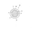
- the plasma generator 12 includes a tubular dielectric 3 (dielectric), an internal electrode 4, and an external electrode 5.
- the tubular dielectric 3 is a cylindrical member extending in the tube axis O1 direction.
- the tubular dielectric 3 has therein a gas flow path 6 extending in the direction of the tube axis O1.
- the active gas passage 7 and the gas passage 6 communicate with each other.
- the tube axis O1 is the same as the tube axis of the tubular dielectric 3.
- a material of the tubular dielectric 3 a dielectric material used for a known plasma device can be applied. Examples of the material of the tubular dielectric 3 include glass, ceramics, and synthetic resin. The lower the dielectric constant of the tubular dielectric 3, the better.
- the tubular dielectric 3 has an internal electrode 4 inside.
- the internal electrode 4 is a substantially columnar member extending in the tube axis O1 direction.
- the internal electrode 4 is separated from the inner surface of the tubular dielectric 3.
- the internal electrode 4 includes a shaft portion extending in the tube axis O1 direction, and a thread on the outer peripheral surface of the shaft portion.
- the shaft may be solid or hollow. Above all, the shaft is preferably solid. If the shaft portion is solid, processing is easy and mechanical durability can be enhanced.
- the screw thread of the internal electrode 4 is a spiral screw thread orbiting in the circumferential direction of the shaft portion.
- the form of the internal electrode 4 is the same as that of the male screw.
- the internal electrode 4 Since the internal electrode 4 has a thread on the outer peripheral surface, the electric field at the tip of the thread is locally increased, and the firing voltage is reduced. Therefore, plasma can be generated and maintained with low power.
- the internal electrode 4 does not need to have unevenness such as a thread on the outer peripheral surface. That is, the internal electrode 4 may be a cylindrical member having no irregularities on the outer peripheral surface.
- the material of the internal electrode 4 is not particularly limited as long as it is a conductive material, and a metal that can be used for an electrode of a known plasma device can be applied.
- Examples of the material of the internal electrode 4 include metals such as stainless steel, copper, and tungsten, and carbon.
- An external electrode 5 along the internal electrode 4 is provided on a part of the outer peripheral surface of the tubular dielectric 3.
- the external electrode 5 is an annular electrode that goes around the outer peripheral surface of the tubular dielectric 3.
- the material of the external electrode 5 is not particularly limited as long as it is a conductive material, and a metal used for an electrode of a known plasma device can be applied. Examples of the material of the external electrode 5 include metals such as stainless steel, copper, and tungsten, and carbon.
- the tubular dielectric 3, the internal electrode 4, and the external electrode 5 are located concentrically with respect to the tube axis O1.
- the outer peripheral surface of the internal electrode 4 and the inner peripheral surface of the external electrode 5 face each other with the tubular dielectric 3 interposed therebetween.
- the plasma generator 12 generates plasma by dielectric barrier discharge.
- the plasma generator 12 generates plasma using, for example, nitrogen.
- the voltage applied to the plasma generation unit 12 increases, and the shield required to prevent electromagnetic waves radiated from the plasma generation unit 12 becomes heavy. For this reason, when the plasma generator 12 is dropped, the dielectric for generating the dielectric barrier discharge is easily broken.
- the plasma generator 12 is detachable from the cowling 11.
- the plasma generation unit 12 is withdrawn from the cowling 11 in the direction of the tube axis O1, for example.
- the plasma generation portion 12 may be configured so that the plasma generation portion 12 is pulled out to the front side with respect to the body portion 11b.
- the head portion 11a side is the front side and the body portion 11b side is the rear side along the axis O1 direction).
- the plasma generator 12 when the plasma generator 12 is damaged, the plasma generator 12 can be detached from the cowling 11 and a new plasma generator 12 can be mounted on the cowling 11. At this time, the new plasma generator 12 can be inserted into the cowling 11 in the direction of the tube axis O1.
- the supply unit 20 as shown in FIG. 1 supplies the irradiation device 10 with electricity and a gas for generating plasma.
- the supply unit 20 can adjust the voltage and frequency applied between the internal electrode 4 and the external electrode 5.
- the supply unit 20 includes a housing 21 that houses the supply source 70.
- the housing 21 is formed in a rectangular parallelepiped box shape.
- the housing 21 houses the supply source 70 detachably. Thereby, when the gas in the supply source 70 accommodated in the housing 21 runs out, the supply source 70 can be replaced.
- the supply source 70 supplies a plasma generation gas to the plasma generation unit 12.
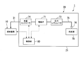
- the supply source 70 is a pressure-resistant container containing a plasma generating gas therein. As shown in FIG. 2, the supply source 70 is detachably attached to a pipe 75 arranged in the housing 21.
- the pipe 75 connects the supply source 70 and the gas pipe 31.
- a solenoid valve 71, a pressure regulator 73, and a flow controller 74 are attached to the pipe 75.
- the electromagnetic valve 71 When the electromagnetic valve 71 is opened, a plasma generating gas is supplied from the supply source 70 to the irradiation device 10 via the pipe 75 and the gas pipe 31.
- the electromagnetic valve 71 is not configured to be able to adjust the valve opening, but is configured to be able to switch only between opening and closing.
- the electromagnetic valve 71 may have a configuration in which the valve opening can be adjusted.
- the pressure regulator 73 is arranged between the solenoid valve 71 and the supply source 70. The pressure regulator 73 reduces the pressure of the plasma generating gas from the supply source 70 toward the electromagnetic valve 71 (reduces the plasma generating gas).
- the flow controller 74 is disposed between the solenoid valve 71 and the gas pipe 31.
- the flow rate controller 74 adjusts the flow rate (supply amount per unit time) of the plasma generating gas passing through the electromagnetic valve 71.
- the flow controller 74 adjusts the flow rate of the plasma generating gas to, for example, 3 L / min.
- a joint 76 is provided at an end of the pipe 75 on the supply source 70 side.
- a supply source 70 is detachably attached to the joint 76.
- the supply source 70 is replaced while the electromagnetic valve 71, the pressure regulator 73, and the flow rate controller 74 (hereinafter, referred to as “the electromagnetic valve 71 etc.”) are fixed to the housing 21. can do.
- the electromagnetic valve 71 and the like can be used for both the supply source 70 before replacement and the supply source 70 after replacement.
- the electromagnetic valve 71 and the like may be fixed to the supply source 70 and may be detachable from the housing 21 integrally with the supply source 70.
- the gas pipe 31 is a path for supplying a plasma generating gas from the supply unit 20 to the irradiation device 10.
- the gas pipe 31 is connected to the rear end of the tubular dielectric 3 of the irradiation device 10.
- the material of the gas pipe 31 is not particularly limited, and a known material used for a gas pipe can be applied. Examples of the material of the gas pipe 31 include a resin pipe and a rubber tube, and a flexible material is preferable. It is preferable that the gas pipe 31 used in the present invention has appropriate strength and also has excellent flexibility.
- the minimum bending radius in the JIS B 8381 method is preferably 1.5 to 5 times, more preferably 1.6 to 4 times, the outer diameter of the gas pipe 31.
- the minimum bending radius is at least 1.5 times the outer diameter of the gas pipe 31, the strength of the gas pipe 31 tends to be sufficiently high. If the minimum bending radius is 5 times or less the outer diameter of the gas pipe 31, sufficient flexibility of the tube can be easily obtained, so that the handling of the irradiation device 10 during operation becomes easy. The same applies to the case where the gas pipe 31 and the electric wiring 32 are put together in one pipe.
- the electric wiring 32 is a wiring for supplying electricity from the supply unit 20 to the irradiation device 10.
- the electric wiring 32 is connected to the internal electrode 4, the external electrode 5, and the operation switch 9 of the irradiation device 10.
- the material of the electric wiring 32 is not particularly limited, and a known material used for electric wiring can be applied. Examples of the material of the electric wiring 32 include a metal conductor covered with an insulating material.
- the control unit 80 as shown in FIG. 2 is configured using an information processing device. That is, the control unit 80 includes a CPU (Central Processor Unit), a memory, and an auxiliary storage device connected by a bus. The control unit 80 operates by executing a program. The control unit 80 may be built in the supply unit 20, for example. The control unit 80 controls the irradiation device 10 and the supply unit 20.
- a CPU Central Processor Unit
- the control unit 80 controls the irradiation device 10 and the supply unit 20.
- the operation switch 9 of the irradiation device 10 is electrically connected to the control unit 80.
- an electric signal is sent from the operation switch 9 to the control unit 80.
- the control unit 80 receives the electric signal, the control unit 80 operates the electromagnetic valve 71 and the flow rate controller 74 and applies a voltage between the internal electrode 4 and the external electrode 5.
- the operation switch 9 is a push button.
- the control unit 80 receives the electric signal. Then, the control unit 80 opens the solenoid valve 71 for a predetermined time, causes the flow rate controller 74 to adjust the flow rate of the plasma generating gas passing through the solenoid valve 71, and sets a voltage between the internal electrode 4 and the external electrode 5. Is applied for a predetermined time.
- a certain amount of plasma generation gas is supplied from the supply source 70 to the plasma generation unit 12, and the active gas is supplied from the irradiation tool 10 for a certain time (for example, about several seconds to several tens of seconds, 30 seconds in this embodiment) It is continuously discharged.
- the wire 90 shown in FIG. 1 is configured by twisting metal strands.
- the wire 90 has flexibility.
- a first end (end (A)) of the wire 90 is fixed to the irradiation device 10.
- the first end of the wire 90 may be detachable from the irradiation device 10 by a metal fitting or the like.
- the linear member is not limited to the wire 90, and may be at least one fiber selected from natural fibers such as cotton and hemp, and synthetic fibers such as polyester fibers, nylon fibers, aramid fibers, acrylic fibers, modacrylic fibers, and polyurethane fibers. May be used as a rope.
- Outrigger 101 is fixed to the lower part of housing 21.
- a pair of support pieces 103 can be protruded and retracted from the main body 102 in a predetermined direction along a horizontal plane.
- the main body 102 is fixed to the lower surface of the housing 21.
- a pair of support pieces 103 of the outrigger 101 are supported by an installation surface S such as a floor surface.
- the installation surface S is a flat surface along a horizontal plane. Since the outrigger 101 is fixed to the housing 21, the housing 21 is less likely to tilt with respect to the installation surface S even if the housing 21 receives a load from the predetermined direction.
- a hanging frame 106 is fixed to the upper surface of the housing 21.
- the housing 21, the outrigger 101, and the hanging frame 106 constitute the support unit 100.
- the hanging frame 106 includes a first vertical frame 107, a horizontal frame 108, a second vertical frame 109, a plurality of reinforcing members 110, and a housing 111.
- the first vertical frame 107 extends upward from the upper surface of the housing 21.
- the horizontal frame 108 extends from the upper end of the first vertical frame 107 along a horizontal plane. It is preferable that the direction in which the horizontal frame 108 extends is a predetermined direction in which the pair of support pieces 103 of the above-described outrigger 101 protrudes and sinks.
- the second vertical frame 109 extends downward from an end of the horizontal frame 108 opposite to the end to which the first vertical frame 107 is fixed.
- One of the reinforcing members 110 is fixed to the upper surface of the housing 21 and the first vertical frame 107, respectively, and reinforces the portion where the upper surface of the housing 21 and the first vertical frame 107 are fixed.
- Another one of the reinforcing members 110 is fixed to the first vertical frame 107 and the horizontal frame 108, respectively, and reinforces a portion where the first vertical frame 107 and the horizontal frame 108 are fixed.
- the first vertical frame 107, the horizontal frame 108, the second vertical frame 109, and the plurality of reinforcing members 110 are formed of, for example, a metal square.
- the housing 111 includes a case 114, a roller 115, and a ratchet mechanism and a biasing member (not shown).
- Case 114 is fixed to the lower end of second vertical frame 109.
- the roller 115 is disposed in the case 114, and is supported by the case 114 so as to be rotatable around a predetermined axis.
- a second end (end (B)) of the wire 90 is fixed to the outer peripheral surface of the roller 115, and a part of the wire 90 is wound. Note that, in this embodiment, the end (B) indicates the end of the part where the wire 90 is not wound on the support 100 side.
- the urging member urges the roller 115 around the axis so that the roller 115 winds the wire 90.
- the wire 90 can be unwound from the roller 115 by pulling out the wire 90 from the case 114 against the urging force of the urging member.
- the ratchet mechanism has a known configuration, and is switchable between a regulated state and a released state. When the ratchet mechanism is set in the restricting state, it is restricted that the roller 115 winds the wire 90 or unwinds the wire 90 from the roller 115. When the ratchet mechanism is released, the roller 115 can wind the wire 90 or unwind the wire 90 from the roller 115.
- FIG. 5 shows a state in which the wire 90 is completely unwound from the roller 115.
- the end (B) of the wire 90 fixed to the support 100 is the end of the wire 90 fixed to the irradiation device 10. It is configured to be arranged at a higher position than (A).
- the height L ⁇ b> 1 of the roller 115 from the installation surface S (floor surface or the ground) at the position where the end portion (B) of the wire 90 is fixed is larger than the length L ⁇ b> 2 of the wire 90.
- the height L1 is not particularly limited, but is required to be at least higher than the height of the irradiation device 10 when the active gas irradiation device 1 is used. Therefore, the height L1 is preferably 100 cm or more, and more preferably 120 cm or more. Is more preferred.
- the upper limit of the height L1 is not particularly limited, but is preferably 200 cm or less, and more preferably 180 cm or less, from the viewpoint of appropriately maintaining the entire size of the active gas irradiation device 1.
- the difference (L1-L2) between the height L1 of the fixed position of the end portion (B) of the wire 90 and the length L2 of the wire 90 is preferably 30 cm to 120 cm, and more preferably 50 cm to 100 cm. More preferred.
- the length L3 of the power / gas supply line 30 is not particularly limited, but is preferably 50 cm to 250 cm, and more preferably 100 cm to 200 cm, from the viewpoint of ensuring good operability of the irradiation device 10. More preferred.
- the L1 can be fixed at an arbitrary length by the above-described mechanism of the storage section 111, the irradiation instrument 10 can be fixed at the height of the treatment target during treatment to improve the accuracy of aiming of plasma or the like. You can also.
- an irradiation target using the active gas irradiation device 1 for example, a cell, a living tissue, a living individual, or the like can be exemplified.
- the living tissue include various organs (such as internal organs), epithelial tissue covering the body surface and the inner surface of a body cavity, periodontal tissue (gingiva, alveolar bone, periodontal ligament, cementum, etc.), teeth, bones, and the like.
- diseases and symptoms that can be treated by irradiation with active gas include diseases in the oral cavity such as gingivitis and periodontal disease, and wounds on the skin.
- the area to which the marker composition is applied is an area to be treated. That is, the application area is a part or all of the affected area, and a wide area including the affected area.
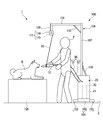
- the irradiation target is a dog and the periodontal tissue of the dog is treated will be described as an example.
- a user P such as a veterinarian, places a dog D on a table 150 arranged on an installation surface S, for example. At this time, the mouth of the dog D is kept open.
- the user P holds the irradiation device 10 and presses the operation switch 9 of the irradiation device 10. Then, electricity and a gas for plasma generation are supplied from the supply unit 20 and the supply source 70 to the irradiation device 10 via the power / gas supply line 30.
- the plasma generating gas supplied to the irradiation device 10 flows into the inner space of the tubular dielectric 3 from the rear end of the tubular dielectric 3 of the plasma generator 12.
- the plasma generating gas is ionized at a position where the internal electrode 4 and the external electrode 5 face each other, and plasma is generated.
- the internal electrode 4 and the external electrode 5 face each other in a direction orthogonal to the direction in which the plasma generating gas flows.
- Plasma generated at a position where the outer peripheral surface of the internal electrode 4 and the inner peripheral surface of the external electrode 5 face each other flows through the gas flow path 6 and the active gas flow path 7 in this order.
- the plasma flows while changing the gas composition, and an active gas containing active species such as radicals is generated by the plasma.
- the irradiation device 10 discharges plasma and active gas (hereinafter, referred to as plasma or the like) from the active gas channel 7 to the outside.
- the user P puts the tip of the irradiation device 10 into the mouth of the dog D, and makes the tip of the irradiation device 10 face the periodontal tissue.
- the treatment is performed by applying plasma or the like to a predetermined portion of the periodontal tissue for a certain period of time. After the treatment of a predetermined part is completed, plasma or the like is applied to another part of the periodontal tissue for a certain time. Thus, the treatment is performed over the entire periodontal tissue in the mouth of the dog D.
- the user P holding the irradiation device 10 drops the irradiation device 10 from the hand for some reason. Even in this case, the irradiation device 10 is fixed to the support portion 100 via the wire 90. For this reason, as shown in FIG. 5, even if the user P releases his / her hand from the irradiation device, the irradiation device 10 is less likely to fall on the installation surface S.
- the irradiation tool 10 when operating the irradiation tool 10 that is not fixed to the support portion 100 via the wire 90, it may be difficult to keep the irradiation tool 10 at a desired position, but in this embodiment, Since the irradiation tool 10 is fixed to the support portion 100 via the wire 90, there is also an advantage that the irradiation tool 10 can be easily held at a desired position. This means that the plasma or the like can be more reliably applied to a predetermined part of the affected part, which can greatly affect the therapeutic effect.
- the support section 100 includes a housing section 111.
- the wire 90 is wound into the housing portion 111.
- the wire 90 is unwound from the housing portion 111. be able to. In this way, the length of the wire 90 protruding outside from the housing 111 can be adjusted.
- the height L1 of the portion of the roller 115 where the end portion (B) of the wire 90 is fixed from the installation surface S (the floor or the ground) is larger than the length L2 of the wire 90. Therefore, when the user P holding the irradiation device 10 drops the irradiation device 10 from his / her hand, the falling irradiation device 10 can be prevented from contacting the installation surface S.
- FIG. 6 the same components as those in FIGS. 1 to 5 for describing the active gas irradiation apparatus of the first embodiment are denoted by the same reference numerals, and description thereof will be omitted.
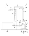
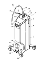
- a power / gas supply line 30 is provided on the upper surface of the supply unit 20 so as to extend upward.
- a gas pipe and electric wiring are collectively accommodated.
- the support portion 100 is configured by a flexible rod 116 provided on the upper surface of the supply unit 20 so as to extend upward, and a fixture 117 having a rotating portion.
- the distal end of the flexible rod 116 is fixed to the power / gas supply line 30 by a binding band 90 as a connecting member, and the root end of the flexible rod 116 is connected to the rotating part of the fixture 117.
- the rotating portion is rotatable in the vertical direction, and is configured to be fixed when the angle of the flexible rod 116 becomes a predetermined angle.
- the flexible rod 116 may be directly fixed to the upper surface of the supply unit 20 without using the fixing tool 117.
- the binding band 90 as a connecting member is not particularly limited as long as the power / gas supply line 30 can be fixed to the distal end portion of the flexible rod 116 without excessively compressing the gas flow path.
- a well-known resin binding band or the like can be used.
- the binding band 90 is made of a metal wire, resin, or metal figure eight ring (which can be fixed in a state where the flexible rod 116 and the power / gas supply line 30 are passed through two holes, respectively). It may be.
- the flexible rod 116 and the binding band 90 hold the middle part of the power / gas supply line 30 at a sufficient height, so that the irradiation device 10 can be prevented from dropping.
- the flexible rod 116 is fixed to the power / gas supply line 30 by the binding band 90 even at a portion other than the tip portion.
- the number of fixing portions other than the tip portion is 3 to 10.
- the power / gas supply line 30 is fixed at a position other than the distal end of the flexible rod 116, the interval between the adjacent fixed positions is 10 cm to 50 cm for a plurality of fixing positions including the distal end. Preferably, it is more preferably 15 cm to 40 cm.
- a member formed of a resin (FRP or CFRP) reinforced with a fiber such as carbon or glass can be used.
- the tip of the flexible rod 116 fixed to the power / gas supply line 30 is higher than the upper surface of the supply unit 20. It is configured to be arranged at a high position.
- the length L2 of the flexible rod 116 is larger than the difference (L3-L4) between the length L3 of the power / gas supply line 30 and the height L4 of the supply unit 20, ie, It is preferable to satisfy the relationship of L2> (L3-L4).
- the difference between the value of L2 and the value of (L3-L4) is determined from the viewpoint of more reliably preventing the user from dropping the irradiation device 10 during use, while ensuring the operability of the irradiation device 10 well.
- the physical properties such as the thickness and elastic modulus of the flexible rod 116 are not particularly limited.
- the height of the distal end of the flexible rod 116 from the upper surface of the supply unit 20 is preferably 10 cm to 10 cm.
- the thickness and physical properties that can be maintained at 100 cm, more preferably about 20 cm to 50 cm may be appropriately selected.
- a holder 22 for holding the irradiation device 10 is further provided on the upper surface of the supply unit 20.
- the holder 22 may also have a configuration in which a rotating portion is provided similarly to the fixing tool 117 so that the holding angle of the irradiation device 10 can be adjusted. Also in this case, it is preferable that the holding angle is fixed at a predetermined angle by a thumb screw or the like.
- the operation panel 23 is provided in front of the upper surface of the supply unit 20.
- the operation panel 23 is connected to the control unit 80, and is configured to adjust the flow rate of the plasma generating gas from the operation panel 23 via the control unit 80.
- the operation panel 23 may be provided with an on / off switch and a standby switch of the supply unit 20, a flow rate display portion of the plasma generating gas, and the like.
- a foot switch holder 27 in which a foot switch 120 is installed is provided at a lower front part of the supply unit 20.
- the foot switch holder 27 is configured to be detachable.
- the foot switch 120 may be operated while the foot switch holder 27 is installed at the lower front part of the supply unit 20, or the foot switch 120 may be operated by removing the foot switch holder 27 and moving it to a desired position. .
- the foot switch holder 27 can be moved by grasping the grip portion 28 of the foot switch holder 27.
- the foot switch 27 can be assigned the same function as the operation switch 9.
- a known switch can be appropriately used, and specific examples include “MKF-MED” manufactured by Nippon Steute.
- a caster 29 is provided at the bottom of the supply unit 20 so that it can be easily moved.
- the casters 29 preferably have a lock / unlock mechanism.
- Known casters can be employed as the casters 29.
- grip portions 24 and 25 are provided, respectively. When the active gas irradiation device 1 is moved, the active gas irradiation device 1 can be moved by holding the grip portions 24 and 25.
- the power / gas supply line 30 is provided on the upper surface of the supply unit 20 so as to extend upward, the power / gas supply line is provided. Damage or the like caused by the contact of the 30 with a wall or the like is suppressed.
- the flexible rod-shaped body 116 ensures the operability of the active gas irradiation device 1 with a simple configuration while maintaining the entire size of the active gas irradiation device 1 compact while the user is in use. The effect of the present invention of preventing the irradiation device from dropping at the same time can be achieved.
- the active gas irradiation device 1 is a device having a configuration suitable for movement and transportation. Further, the supply unit 20 is configured so that the back cover thereof can be removed by holding the handle portion 26 and the inside of the supply unit 20 can be accessed.
- the active gas irradiation device 1 may not include the storage unit 111, and the second end of the wire 90 may be directly fixed to the lower end of the second vertical frame 109.
- the linear member may be formed of an elastic material such as a helical spring. The spring constant of the linear member may be set so that the linear member does not come into contact with the installation surface S even if the linear member extends under the load of the irradiation device 10 and the power / gas supply line 30.
- the irradiation device 10 may be configured to discharge only one of the plasma and the active gas.
- the first end of the wire 90 may be configured to be fixed to at least one of the gas tube 31 and the electric wiring 32 that is the power / gas supply line 30.
- the first end of the wire 90 may be configured to be fixed to at least one of the gas pipe 31 and the electric wiring 32 and the irradiation device 10.
- the plasma irradiation device may be used for humans and non-human animals, or the plasma irradiation device may be used only for non-human animals.
- the plasma irradiation device described above can be suitably used for applications such as treatment of animals and humans, beauty treatment, and the like.
- Active gas irradiation device (plasma irradiation device) DESCRIPTION OF SYMBOLS 10 Irradiation apparatus 12 Plasma generation part 30 Power / gas supply line 90 Connecting member 100 Support part 111 Housing part L1 Height from installation surface L2 Length of linear member S Installation surface (floor surface or ground)
Landscapes
- Engineering & Computer Science (AREA)
- Health & Medical Sciences (AREA)
- Physics & Mathematics (AREA)
- Plasma & Fusion (AREA)
- Life Sciences & Earth Sciences (AREA)
- General Health & Medical Sciences (AREA)
- Animal Behavior & Ethology (AREA)
- Spectroscopy & Molecular Physics (AREA)
- Veterinary Medicine (AREA)
- Public Health (AREA)
- Nuclear Medicine, Radiotherapy & Molecular Imaging (AREA)
- Biomedical Technology (AREA)
- Surgery (AREA)
- Fluid Mechanics (AREA)
- Radiology & Medical Imaging (AREA)
- Heart & Thoracic Surgery (AREA)
- Medical Informatics (AREA)
- Molecular Biology (AREA)
- Oral & Maxillofacial Surgery (AREA)
- Chemical & Material Sciences (AREA)
- Pathology (AREA)
- Epidemiology (AREA)
- Dentistry (AREA)
- Toxicology (AREA)
- Otolaryngology (AREA)
- Organic Chemistry (AREA)
- Chemical Kinetics & Catalysis (AREA)
- Plasma Technology (AREA)
- Electrotherapy Devices (AREA)
- Surgical Instruments (AREA)
- Dental Tools And Instruments Or Auxiliary Dental Instruments (AREA)
Abstract
Cet appareil d'irradiation par plasma comprend : un instrument d'irradiation qui comporte une partie de génération de plasma et qui évacue un plasma généré par la partie de génération de plasma et/ou un gaz actif généré par le plasma; une unité d'alimentation qui fournit de l'électricité et un gaz pour la génération de plasma vers l'instrument d'irradiation; une partie de support qui s'étend vers le haut à partir de l'unité d'alimentation; une conduite d'alimentation en électricité/gaz qui relie l'instrument d'irradiation et l'unité d'alimentation; et un élément de raccordement qui relie la partie de support à l'instrument d'irradiation et/ou à la conduite d'alimentation en électricité/gaz. L'instrument d'irradiation est retenu, par la partie de support et l'élément de raccordement, à une position supérieure au plan d'installation de l'unité d'alimentation.
Priority Applications (3)
| Application Number | Priority Date | Filing Date | Title |
|---|---|---|---|
| US17/055,236 US20210213298A1 (en) | 2018-06-29 | 2019-06-28 | Plasma application apparatus |
| EP19824894.0A EP3815740A4 (fr) | 2018-06-29 | 2019-06-28 | Appareil d'irradiation par plasma |
| JP2020527699A JP6916393B2 (ja) | 2018-06-29 | 2019-06-28 | プラズマ照射装置 |
Applications Claiming Priority (2)
| Application Number | Priority Date | Filing Date | Title |
|---|---|---|---|
| JP2018124456 | 2018-06-29 | ||
| JP2018-124456 | 2018-06-29 |
Publications (1)
| Publication Number | Publication Date |
|---|---|
| WO2020004650A1 true WO2020004650A1 (fr) | 2020-01-02 |
Family
ID=68985955
Family Applications (1)
| Application Number | Title | Priority Date | Filing Date |
|---|---|---|---|
| PCT/JP2019/025929 WO2020004650A1 (fr) | 2018-06-29 | 2019-06-28 | Appareil d'irradiation par plasma |
Country Status (4)
| Country | Link |
|---|---|
| US (1) | US20210213298A1 (fr) |
| EP (1) | EP3815740A4 (fr) |
| JP (1) | JP6916393B2 (fr) |
| WO (1) | WO2020004650A1 (fr) |
Citations (6)
| Publication number | Priority date | Publication date | Assignee | Title |
|---|---|---|---|---|
| JPS5441066B2 (fr) | 1973-03-26 | 1979-12-06 | ||
| JPS6259007U (fr) * | 1985-10-01 | 1987-04-13 | ||
| JPH07299104A (ja) * | 1994-05-02 | 1995-11-14 | Morita Tokyo Seisakusho:Kk | 歯科用ユニットのメインチューブの垂れ下がり防止兼引き込み加勢装置 |
| JP2006254986A (ja) * | 2005-03-15 | 2006-09-28 | Hoya Photonics Corp | レーザ装置 |
| JP2017050267A (ja) | 2015-08-31 | 2017-03-09 | 積水化学工業株式会社 | プラズマ装置及びその使用方法並びに窒素ガスプラズマ及びその照射方法 |
| US20170339776A1 (en) * | 2014-11-04 | 2017-11-23 | Fourth State Medicine Ltd | Plasma generation |
Family Cites Families (11)
| Publication number | Priority date | Publication date | Assignee | Title |
|---|---|---|---|---|
| JP2501030Y2 (ja) * | 1993-03-29 | 1996-06-12 | 株式会社アイエル | 器具等の自在位置固定装置 |
| JP3057065B2 (ja) * | 1997-12-03 | 2000-06-26 | 松下電工株式会社 | プラズマ処理装置及びプラズマ処理方法 |
| US6280439B1 (en) * | 1999-07-12 | 2001-08-28 | Cryocath Technologies, Inc. | Adjustable position injection tubing |
| WO2001005197A2 (fr) * | 1999-07-13 | 2001-01-18 | Nordson Corporation | Systeme de traitement au plasma symetrique et haute vitesse- |
| KR101158800B1 (ko) * | 2008-11-14 | 2012-06-26 | 주식회사 피에스엠 | 의료용 플라즈마 건 |
| DE102010011643B4 (de) * | 2010-03-16 | 2024-05-29 | Christian Buske | Vorrichtung und Verfahren zur Plasmabehandlung von lebendem Gewebe |
| IT1403871B1 (it) * | 2011-02-11 | 2013-11-08 | El En Spa | "dispositivo e metodo di trattamento laser della pelle" |
| JP5980501B2 (ja) * | 2011-12-22 | 2016-08-31 | 長田電機工業株式会社 | プラズマ治療器 |
| EP3135445B1 (fr) * | 2014-03-28 | 2021-04-28 | Sony Corporation | Dispositif de bras robotique |
| US20170361078A1 (en) * | 2014-12-10 | 2017-12-21 | Devicefarm, Inc. | Onychomycosis treatment system and method |
| US10912598B2 (en) * | 2017-08-04 | 2021-02-09 | Us Patent Innovations, Llc | Diffusive applicator for cold atmospheric plasma system |
-
2019
- 2019-06-28 US US17/055,236 patent/US20210213298A1/en not_active Abandoned
- 2019-06-28 EP EP19824894.0A patent/EP3815740A4/fr not_active Withdrawn
- 2019-06-28 JP JP2020527699A patent/JP6916393B2/ja active Active
- 2019-06-28 WO PCT/JP2019/025929 patent/WO2020004650A1/fr active Application Filing
Patent Citations (6)
| Publication number | Priority date | Publication date | Assignee | Title |
|---|---|---|---|---|
| JPS5441066B2 (fr) | 1973-03-26 | 1979-12-06 | ||
| JPS6259007U (fr) * | 1985-10-01 | 1987-04-13 | ||
| JPH07299104A (ja) * | 1994-05-02 | 1995-11-14 | Morita Tokyo Seisakusho:Kk | 歯科用ユニットのメインチューブの垂れ下がり防止兼引き込み加勢装置 |
| JP2006254986A (ja) * | 2005-03-15 | 2006-09-28 | Hoya Photonics Corp | レーザ装置 |
| US20170339776A1 (en) * | 2014-11-04 | 2017-11-23 | Fourth State Medicine Ltd | Plasma generation |
| JP2017050267A (ja) | 2015-08-31 | 2017-03-09 | 積水化学工業株式会社 | プラズマ装置及びその使用方法並びに窒素ガスプラズマ及びその照射方法 |
Non-Patent Citations (1)
| Title |
|---|
| See also references of EP3815740A4 |
Also Published As
| Publication number | Publication date |
|---|---|
| EP3815740A4 (fr) | 2022-03-23 |
| JPWO2020004650A1 (ja) | 2021-03-11 |
| JP6916393B2 (ja) | 2021-08-11 |
| EP3815740A1 (fr) | 2021-05-05 |
| US20210213298A1 (en) | 2021-07-15 |
Similar Documents
| Publication | Publication Date | Title |
|---|---|---|
| JP6677855B2 (ja) | 活性ガス照射装置及びヒトを除く動物の治療方法 | |
| JP6916393B2 (ja) | プラズマ照射装置 | |
| JP2020047530A (ja) | プラズマ照射装置 | |
| JP2020149953A (ja) | プラズマ装置 | |
| JP6936190B2 (ja) | プラズマ式治療装置 | |
| JP7000523B1 (ja) | プラズマ装置 | |
| JP2020028384A (ja) | プラズマ式治療装置 | |
| WO2022054466A1 (fr) | Équipement d'irradiation, dispositif d'irradiation de plasma et tube d'irradiation | |
| WO2020059809A1 (fr) | Dispositif d'irradiation plasma | |
| JP7032273B2 (ja) | プラズマ照射装置 | |
| JP6916317B2 (ja) | プラズマ式治療装置およびプラズマ式治療装置用のカバー | |
| EP4124179A1 (fr) | Élément de support, instrument d'irradiation et dispositif à plasma | |
| JP7016779B2 (ja) | プラズマ式治療装置 | |
| JP7088791B2 (ja) | プラズマ式治療装置 | |
| JP2020010770A (ja) | プラズマ照射装置 | |
| JP2020000405A (ja) | プラズマ式治療装置 | |
| US20230156899A1 (en) | Irradiator and plasma apparatus | |
| JP6916362B1 (ja) | 保持部材、照射器具及びプラズマ装置 | |
| JPWO2019093388A1 (ja) | プラズマ式治療装置 | |
| JP2020039673A (ja) | プラズマ式治療装置 | |
| JP2020039495A (ja) | プラズマ式治療装置 | |
| JP6919043B1 (ja) | 照射器具及びプラズマ装置 | |
| JP2020006098A (ja) | プラズマ照射装置 | |
| JP2023142440A (ja) | 糜爛又は潰瘍の予防方法、疾患の治療方法、糜爛又は潰瘍の予防用照射ガス及び糜爛又は潰瘍の予防用照射ガスの生成方法 | |
| JP2020030996A (ja) | プラズマ照射装置、ノズル洗浄装置 |
Legal Events
| Date | Code | Title | Description |
|---|---|---|---|
| 121 | Ep: the epo has been informed by wipo that ep was designated in this application |
Ref document number: 19824894 Country of ref document: EP Kind code of ref document: A1 |
|
| ENP | Entry into the national phase |
Ref document number: 2020527699 Country of ref document: JP Kind code of ref document: A |
|
| NENP | Non-entry into the national phase |
Ref country code: DE |
|
| WWE | Wipo information: entry into national phase |
Ref document number: 2019824894 Country of ref document: EP |