WO2020004650A1 - Plasma irradiation apparatus - Google Patents
Plasma irradiation apparatus Download PDFInfo
- Publication number
- WO2020004650A1 WO2020004650A1 PCT/JP2019/025929 JP2019025929W WO2020004650A1 WO 2020004650 A1 WO2020004650 A1 WO 2020004650A1 JP 2019025929 W JP2019025929 W JP 2019025929W WO 2020004650 A1 WO2020004650 A1 WO 2020004650A1
- Authority
- WO
- WIPO (PCT)
- Prior art keywords
- plasma
- gas
- irradiation device
- irradiation
- fixed
- Prior art date
Links
Images

Classifications
-
- A—HUMAN NECESSITIES
- A61—MEDICAL OR VETERINARY SCIENCE; HYGIENE
- A61C—DENTISTRY; APPARATUS OR METHODS FOR ORAL OR DENTAL HYGIENE
- A61C19/00—Dental auxiliary appliances
- A61C19/06—Implements for therapeutic treatment
-
- A—HUMAN NECESSITIES
- A61—MEDICAL OR VETERINARY SCIENCE; HYGIENE
- A61B—DIAGNOSIS; SURGERY; IDENTIFICATION
- A61B18/00—Surgical instruments, devices or methods for transferring non-mechanical forms of energy to or from the body
- A61B18/04—Surgical instruments, devices or methods for transferring non-mechanical forms of energy to or from the body by heating
- A61B18/042—Surgical instruments, devices or methods for transferring non-mechanical forms of energy to or from the body by heating using additional gas becoming plasma
-
- A—HUMAN NECESSITIES
- A61—MEDICAL OR VETERINARY SCIENCE; HYGIENE
- A61B—DIAGNOSIS; SURGERY; IDENTIFICATION
- A61B90/00—Instruments, implements or accessories specially adapted for surgery or diagnosis and not covered by any of the groups A61B1/00 - A61B50/00, e.g. for luxation treatment or for protecting wound edges
- A61B90/50—Supports for surgical instruments, e.g. articulated arms
-
- A—HUMAN NECESSITIES
- A61—MEDICAL OR VETERINARY SCIENCE; HYGIENE
- A61N—ELECTROTHERAPY; MAGNETOTHERAPY; RADIATION THERAPY; ULTRASOUND THERAPY
- A61N1/00—Electrotherapy; Circuits therefor
- A61N1/44—Applying ionised fluids
-
- B—PERFORMING OPERATIONS; TRANSPORTING
- B01—PHYSICAL OR CHEMICAL PROCESSES OR APPARATUS IN GENERAL
- B01J—CHEMICAL OR PHYSICAL PROCESSES, e.g. CATALYSIS OR COLLOID CHEMISTRY; THEIR RELEVANT APPARATUS
- B01J19/00—Chemical, physical or physico-chemical processes in general; Their relevant apparatus
- B01J19/08—Processes employing the direct application of electric or wave energy, or particle radiation; Apparatus therefor
- B01J19/087—Processes employing the direct application of electric or wave energy, or particle radiation; Apparatus therefor employing electric or magnetic energy
- B01J19/088—Processes employing the direct application of electric or wave energy, or particle radiation; Apparatus therefor employing electric or magnetic energy giving rise to electric discharges
-
- H—ELECTRICITY
- H05—ELECTRIC TECHNIQUES NOT OTHERWISE PROVIDED FOR
- H05H—PLASMA TECHNIQUE; PRODUCTION OF ACCELERATED ELECTRICALLY-CHARGED PARTICLES OR OF NEUTRONS; PRODUCTION OR ACCELERATION OF NEUTRAL MOLECULAR OR ATOMIC BEAMS
- H05H1/00—Generating plasma; Handling plasma
- H05H1/24—Generating plasma
- H05H1/2406—Generating plasma using dielectric barrier discharges, i.e. with a dielectric interposed between the electrodes
- H05H1/2443—Generating plasma using dielectric barrier discharges, i.e. with a dielectric interposed between the electrodes the plasma fluid flowing through a dielectric tube
- H05H1/245—Generating plasma using dielectric barrier discharges, i.e. with a dielectric interposed between the electrodes the plasma fluid flowing through a dielectric tube the plasma being activated using internal electrodes
-
- H—ELECTRICITY
- H05—ELECTRIC TECHNIQUES NOT OTHERWISE PROVIDED FOR
- H05H—PLASMA TECHNIQUE; PRODUCTION OF ACCELERATED ELECTRICALLY-CHARGED PARTICLES OR OF NEUTRONS; PRODUCTION OR ACCELERATION OF NEUTRAL MOLECULAR OR ATOMIC BEAMS
- H05H1/00—Generating plasma; Handling plasma
- H05H1/24—Generating plasma
- H05H1/2406—Generating plasma using dielectric barrier discharges, i.e. with a dielectric interposed between the electrodes
- H05H1/2443—Generating plasma using dielectric barrier discharges, i.e. with a dielectric interposed between the electrodes the plasma fluid flowing through a dielectric tube
- H05H1/246—Generating plasma using dielectric barrier discharges, i.e. with a dielectric interposed between the electrodes the plasma fluid flowing through a dielectric tube the plasma being activated using external electrodes
-
- A—HUMAN NECESSITIES
- A61—MEDICAL OR VETERINARY SCIENCE; HYGIENE
- A61B—DIAGNOSIS; SURGERY; IDENTIFICATION
- A61B18/00—Surgical instruments, devices or methods for transferring non-mechanical forms of energy to or from the body
- A61B2018/00315—Surgical instruments, devices or methods for transferring non-mechanical forms of energy to or from the body for treatment of particular body parts
- A61B2018/00452—Skin
- A61B2018/0047—Upper parts of the skin, e.g. skin peeling or treatment of wrinkles
-
- A—HUMAN NECESSITIES
- A61—MEDICAL OR VETERINARY SCIENCE; HYGIENE
- A61B—DIAGNOSIS; SURGERY; IDENTIFICATION
- A61B18/00—Surgical instruments, devices or methods for transferring non-mechanical forms of energy to or from the body
- A61B2018/00636—Sensing and controlling the application of energy
- A61B2018/00696—Controlled or regulated parameters
- A61B2018/00744—Fluid flow
-
- H—ELECTRICITY
- H05—ELECTRIC TECHNIQUES NOT OTHERWISE PROVIDED FOR
- H05H—PLASMA TECHNIQUE; PRODUCTION OF ACCELERATED ELECTRICALLY-CHARGED PARTICLES OR OF NEUTRONS; PRODUCTION OR ACCELERATION OF NEUTRAL MOLECULAR OR ATOMIC BEAMS
- H05H2245/00—Applications of plasma devices
- H05H2245/30—Medical applications
- H05H2245/34—Skin treatments, e.g. disinfection or wound treatment
Definitions
- the present invention relates to a plasma irradiation device.
- a plasma irradiation apparatus for medical use such as dental treatment is known.
- the plasma irradiation device cures an affected part such as a wound by irradiating the affected part with plasma or active gas.
- the active gas is generated by plasma in a plasma irradiation device.
- Patent Literature 1 discloses a plasma jet irradiation apparatus for performing dental treatment.
- the plasma jet irradiation apparatus includes an irradiation device having plasma jet irradiation means.
- the plasma jet irradiation device irradiates the object to be irradiated with the generated plasma and the active species.
- the active species are generated by a reaction between a gas in the plasma or a gas around the plasma and the plasma.
- Patent Literature 2 discloses a plasma irradiation apparatus that generates an active gas (active species) inside an irradiation tool, discharges the active gas from a nozzle, and irradiates an affected part with the gas.
- the active gas is, for example, active oxygen or active nitrogen.
- the irradiation tool may drop on the floor or the like during the treatment by the user. Such a drop is not desirable because it may lead to damage or failure of the irradiation device.
- the movable range of the irradiation tool is strongly restricted in order to prevent such a fall, the operability of the irradiation tool may be poor. Therefore, there is a need for an improvement for preventing the irradiation device from falling while ensuring the operability of the irradiation device.
- the present invention has been made in view of such a problem, and provides a plasma irradiation apparatus that suppresses a user from dropping an irradiation tool during use while ensuring operability of the irradiation tool.
- the purpose is to:
- the plasma irradiation apparatus of the present invention has a plasma generation unit, an irradiation device for discharging at least one of plasma generated in the plasma generation unit and an active gas generated by the plasma, and a power and plasma generation device for the irradiation device.
- a connecting member for connecting the supporting unit and the supporting unit, wherein the supporting unit and the connecting member maintain the irradiation device at a position above the installation surface of the supply unit. It is characterized by:
- the irradiation device and the power / gas supply line is connected to the support portion via the connecting member. Fixed. For this reason, even if the user releases his hand from the irradiation device, the downward movement of the irradiation device is restricted, and the user can be prevented from falling down during use. Furthermore, since the fixing to the support portion is via the connecting member, the freedom of movement of the irradiation tool in a direction other than below when operating the irradiation tool is appropriately secured. Therefore, the operability of the plasma irradiation device is also well ensured.
- the connecting member is a linear member, and one end (A) of the linear member is fixed to at least one of the irradiation device and the power / gas supply line,
- the other end (B) of the member may be fixed to the support portion, and the support portion may have a housing portion that can wind the linear member and can unwind the linear member.
- the linear member when the length of the linear member is not relatively long, the linear member is rolled into the housing portion, and when the length of the linear member is relatively long, the linear member is The member can be unwound from the housing. In this way, it is possible to adjust the length of the linear member protruding from the housing to the outside.
- one end (A) of the linear member is fixed to the irradiation device, and the other end (B) of the linear member in the support portion is fixed to the one end.
- positioned at a higher position and the length of the said linear member may be smaller than the height from the floor surface or the ground of the location to which the said other end (B) was fixed.
- the support member includes a flexible rod
- the connecting member is a binding band for fixing the flexible rod and the power / gas supply line.
- a gas supply line and the flexible rod are disposed on the upper surface of the supply unit so as to extend upward, and an intermediate portion of the power / gas supply line is formed of a flexible rod by the binding band.
- an intermediate portion of the power / gas supply line may be maintained at a position higher than the upper surface of the supply unit.
- the flexible rod-shaped body has a simple configuration, and the operability of the active gas irradiation device is ensured while maintaining the compact size of the active gas irradiation device as a whole. Can be prevented from dropping.
- the plasma generation unit may generate the plasma by dielectric barrier discharge.
- the plasma generation unit may generate the plasma using nitrogen gas.
- the plasma irradiation apparatus of the present invention it is possible to prevent the user from dropping the irradiation tool during use while ensuring the operability of the irradiation tool.
- FIG. 4 is a sectional view taken along line A1-A1 of the irradiation device of FIG. It is a schematic diagram which shows the state which the user dropped the irradiation tool when using the active gas irradiation apparatus. It is a schematic diagram which shows the active gas irradiation apparatus of the second embodiment of the present invention.
- the plasma irradiation device of the present embodiment is a plasma jet irradiation device or an active gas irradiation device.
- the plasma jet irradiation device generates plasma.
- the plasma jet irradiation device directly irradiates the generated plasma and active species to an irradiation target (object to be irradiated).
- the active species are generated by a reaction between a gas in the plasma or a gas around the plasma and the plasma. Examples of the active species include active oxygen species and active nitrogen species.
- the active oxygen species include a hydroxyl radical, singlet oxygen, ozone, hydrogen peroxide, and a superoxide anion radical.
- the active nitrogen species include nitric oxide, nitrogen dioxide, peroxynitrite, nitrous oxide, nitrous oxide and the like.
- the active gas irradiation device generates plasma and irradiates an irradiation target with an active gas containing active species generated by the plasma.
- the active species are generated by a reaction between a gas in the plasma or a gas around the plasma and the plasma.
- the plasma irradiation device is an active gas irradiation device will be described as an example.
- the active gas irradiation device 1 of the present embodiment includes an irradiation device 10, a supply unit 20, a power / gas supply line 30, a supply source 70, a control unit 80, a wire (Linear member) 90 and a support portion 100.
- the irradiation device 10 discharges the active gas generated in the irradiation device 10.
- the supply unit 20 supplies power and a gas for plasma generation to the irradiation device 10.
- the plasma generation gas include rare gases such as helium, neon, argon, and krypton; and nitrogen (nitrogen gas). These gases may be supplied alone or in combination of two or more.
- the plasma generating gas preferably contains nitrogen as a main component.
- “mainly containing nitrogen” means that the content of nitrogen in the plasma generating gas is more than 50% by volume.
- the supply unit 20 contains a supply source 70.
- the supply source 70 contains a plasma generating gas.
- the supply unit 20 is connected to a power supply (not shown) such as a household power supply of 100 V, for example.
- the power / gas supply line 30 includes a gas pipe 31 and an electric wiring 32.
- the gas pipe 31 connects the irradiation device 10 and the supply unit 20.
- the electric wiring 32 connects the irradiation device 10 and the supply unit 20.
- the gas pipe 31 and the electric wiring 32 are independent of each other, but the gas pipe 31 and the electric wiring 32 may be integrated.
- FIG. 3 is a cross-sectional (longitudinal) view of a plane along the axis of the irradiation device 10.
- the irradiation device 10 includes a long cowling 11 and a plasma generation unit 12 located in the cowling 11.
- the cowling 11 includes a cylindrical body 11b and a head 11a that closes a tip of the body 11b.
- the body 11b is not limited to a cylindrical shape, but may be a polygonal cylindrical shape such as a square tube, a hexagonal tube, and an octagonal tube.
- the head 11a is gradually narrowed toward the tip. That is, the head 11a in the present embodiment has a conical shape.
- the head 11a is not limited to a conical shape, and may be a polygonal pyramid such as a quadrangular pyramid, a hexagonal pyramid, or an octagonal pyramid.
- the head 11a has an active gas flow path 7 extending in the direction of the tube axis O1 therein.
- the tube axis O1 is the tube axis of the body 11b.
- the material of the head 11a is not particularly limited, and may have insulating properties or may not have insulating properties.
- the material of the head portion 11a is preferably a material having excellent wear resistance and corrosion resistance. As a material having excellent wear resistance and corrosion resistance, a metal such as stainless steel can be exemplified.
- the material of the body 11b is not particularly limited, but is preferably a material having an insulating property.
- the body 11b may be formed of only an electrically insulating material, or may have a multilayer structure having an electrically insulating material and a metal material layer on its surface.
- the insulating material include a thermoplastic resin and a thermosetting resin.
- the thermoplastic resin include polyethylene, polypropylene, polyvinyl chloride, polystyrene, acrylonitrile-butadiene-styrene resin (ABS resin) and the like.
- the thermosetting resin include a phenol resin, a melamine resin, a urea resin, an epoxy resin, an unsaturated polyester resin, and a silicone resin.
- the metal material examples include stainless steel, titanium, and aluminum.
- the material of the body 11b and the material of the head 11a may be the same or different.
- the size of the body 11b is not particularly limited, and may be a size that can be easily grasped with fingers.
- the body 11b has an operation switch 9 (operation unit) on the outer peripheral surface. Note that the operation switch 9 may not be provided on the irradiation device 10 but may be provided on the supply unit 20 or may be provided as a foot switch.
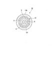
- the plasma generator 12 includes a tubular dielectric 3 (dielectric), an internal electrode 4, and an external electrode 5.
- the tubular dielectric 3 is a cylindrical member extending in the tube axis O1 direction.
- the tubular dielectric 3 has therein a gas flow path 6 extending in the direction of the tube axis O1.
- the active gas passage 7 and the gas passage 6 communicate with each other.
- the tube axis O1 is the same as the tube axis of the tubular dielectric 3.
- a material of the tubular dielectric 3 a dielectric material used for a known plasma device can be applied. Examples of the material of the tubular dielectric 3 include glass, ceramics, and synthetic resin. The lower the dielectric constant of the tubular dielectric 3, the better.
- the tubular dielectric 3 has an internal electrode 4 inside.
- the internal electrode 4 is a substantially columnar member extending in the tube axis O1 direction.
- the internal electrode 4 is separated from the inner surface of the tubular dielectric 3.
- the internal electrode 4 includes a shaft portion extending in the tube axis O1 direction, and a thread on the outer peripheral surface of the shaft portion.
- the shaft may be solid or hollow. Above all, the shaft is preferably solid. If the shaft portion is solid, processing is easy and mechanical durability can be enhanced.
- the screw thread of the internal electrode 4 is a spiral screw thread orbiting in the circumferential direction of the shaft portion.
- the form of the internal electrode 4 is the same as that of the male screw.
- the internal electrode 4 Since the internal electrode 4 has a thread on the outer peripheral surface, the electric field at the tip of the thread is locally increased, and the firing voltage is reduced. Therefore, plasma can be generated and maintained with low power.
- the internal electrode 4 does not need to have unevenness such as a thread on the outer peripheral surface. That is, the internal electrode 4 may be a cylindrical member having no irregularities on the outer peripheral surface.
- the material of the internal electrode 4 is not particularly limited as long as it is a conductive material, and a metal that can be used for an electrode of a known plasma device can be applied.
- Examples of the material of the internal electrode 4 include metals such as stainless steel, copper, and tungsten, and carbon.
- An external electrode 5 along the internal electrode 4 is provided on a part of the outer peripheral surface of the tubular dielectric 3.
- the external electrode 5 is an annular electrode that goes around the outer peripheral surface of the tubular dielectric 3.
- the material of the external electrode 5 is not particularly limited as long as it is a conductive material, and a metal used for an electrode of a known plasma device can be applied. Examples of the material of the external electrode 5 include metals such as stainless steel, copper, and tungsten, and carbon.
- the tubular dielectric 3, the internal electrode 4, and the external electrode 5 are located concentrically with respect to the tube axis O1.
- the outer peripheral surface of the internal electrode 4 and the inner peripheral surface of the external electrode 5 face each other with the tubular dielectric 3 interposed therebetween.
- the plasma generator 12 generates plasma by dielectric barrier discharge.
- the plasma generator 12 generates plasma using, for example, nitrogen.
- the voltage applied to the plasma generation unit 12 increases, and the shield required to prevent electromagnetic waves radiated from the plasma generation unit 12 becomes heavy. For this reason, when the plasma generator 12 is dropped, the dielectric for generating the dielectric barrier discharge is easily broken.
- the plasma generator 12 is detachable from the cowling 11.
- the plasma generation unit 12 is withdrawn from the cowling 11 in the direction of the tube axis O1, for example.
- the plasma generation portion 12 may be configured so that the plasma generation portion 12 is pulled out to the front side with respect to the body portion 11b.
- the head portion 11a side is the front side and the body portion 11b side is the rear side along the axis O1 direction).
- the plasma generator 12 when the plasma generator 12 is damaged, the plasma generator 12 can be detached from the cowling 11 and a new plasma generator 12 can be mounted on the cowling 11. At this time, the new plasma generator 12 can be inserted into the cowling 11 in the direction of the tube axis O1.
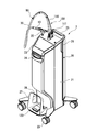
- the supply unit 20 as shown in FIG. 1 supplies the irradiation device 10 with electricity and a gas for generating plasma.
- the supply unit 20 can adjust the voltage and frequency applied between the internal electrode 4 and the external electrode 5.
- the supply unit 20 includes a housing 21 that houses the supply source 70.
- the housing 21 is formed in a rectangular parallelepiped box shape.
- the housing 21 houses the supply source 70 detachably. Thereby, when the gas in the supply source 70 accommodated in the housing 21 runs out, the supply source 70 can be replaced.
- the supply source 70 supplies a plasma generation gas to the plasma generation unit 12.
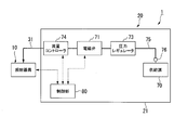
- the supply source 70 is a pressure-resistant container containing a plasma generating gas therein. As shown in FIG. 2, the supply source 70 is detachably attached to a pipe 75 arranged in the housing 21.
- the pipe 75 connects the supply source 70 and the gas pipe 31.
- a solenoid valve 71, a pressure regulator 73, and a flow controller 74 are attached to the pipe 75.
- the electromagnetic valve 71 When the electromagnetic valve 71 is opened, a plasma generating gas is supplied from the supply source 70 to the irradiation device 10 via the pipe 75 and the gas pipe 31.
- the electromagnetic valve 71 is not configured to be able to adjust the valve opening, but is configured to be able to switch only between opening and closing.
- the electromagnetic valve 71 may have a configuration in which the valve opening can be adjusted.
- the pressure regulator 73 is arranged between the solenoid valve 71 and the supply source 70. The pressure regulator 73 reduces the pressure of the plasma generating gas from the supply source 70 toward the electromagnetic valve 71 (reduces the plasma generating gas).
- the flow controller 74 is disposed between the solenoid valve 71 and the gas pipe 31.
- the flow rate controller 74 adjusts the flow rate (supply amount per unit time) of the plasma generating gas passing through the electromagnetic valve 71.
- the flow controller 74 adjusts the flow rate of the plasma generating gas to, for example, 3 L / min.
- a joint 76 is provided at an end of the pipe 75 on the supply source 70 side.
- a supply source 70 is detachably attached to the joint 76.
- the supply source 70 is replaced while the electromagnetic valve 71, the pressure regulator 73, and the flow rate controller 74 (hereinafter, referred to as “the electromagnetic valve 71 etc.”) are fixed to the housing 21. can do.
- the electromagnetic valve 71 and the like can be used for both the supply source 70 before replacement and the supply source 70 after replacement.
- the electromagnetic valve 71 and the like may be fixed to the supply source 70 and may be detachable from the housing 21 integrally with the supply source 70.
- the gas pipe 31 is a path for supplying a plasma generating gas from the supply unit 20 to the irradiation device 10.
- the gas pipe 31 is connected to the rear end of the tubular dielectric 3 of the irradiation device 10.
- the material of the gas pipe 31 is not particularly limited, and a known material used for a gas pipe can be applied. Examples of the material of the gas pipe 31 include a resin pipe and a rubber tube, and a flexible material is preferable. It is preferable that the gas pipe 31 used in the present invention has appropriate strength and also has excellent flexibility.
- the minimum bending radius in the JIS B 8381 method is preferably 1.5 to 5 times, more preferably 1.6 to 4 times, the outer diameter of the gas pipe 31.
- the minimum bending radius is at least 1.5 times the outer diameter of the gas pipe 31, the strength of the gas pipe 31 tends to be sufficiently high. If the minimum bending radius is 5 times or less the outer diameter of the gas pipe 31, sufficient flexibility of the tube can be easily obtained, so that the handling of the irradiation device 10 during operation becomes easy. The same applies to the case where the gas pipe 31 and the electric wiring 32 are put together in one pipe.
- the electric wiring 32 is a wiring for supplying electricity from the supply unit 20 to the irradiation device 10.
- the electric wiring 32 is connected to the internal electrode 4, the external electrode 5, and the operation switch 9 of the irradiation device 10.
- the material of the electric wiring 32 is not particularly limited, and a known material used for electric wiring can be applied. Examples of the material of the electric wiring 32 include a metal conductor covered with an insulating material.
- the control unit 80 as shown in FIG. 2 is configured using an information processing device. That is, the control unit 80 includes a CPU (Central Processor Unit), a memory, and an auxiliary storage device connected by a bus. The control unit 80 operates by executing a program. The control unit 80 may be built in the supply unit 20, for example. The control unit 80 controls the irradiation device 10 and the supply unit 20.
- a CPU Central Processor Unit
- the control unit 80 controls the irradiation device 10 and the supply unit 20.
- the operation switch 9 of the irradiation device 10 is electrically connected to the control unit 80.
- an electric signal is sent from the operation switch 9 to the control unit 80.
- the control unit 80 receives the electric signal, the control unit 80 operates the electromagnetic valve 71 and the flow rate controller 74 and applies a voltage between the internal electrode 4 and the external electrode 5.
- the operation switch 9 is a push button.
- the control unit 80 receives the electric signal. Then, the control unit 80 opens the solenoid valve 71 for a predetermined time, causes the flow rate controller 74 to adjust the flow rate of the plasma generating gas passing through the solenoid valve 71, and sets a voltage between the internal electrode 4 and the external electrode 5. Is applied for a predetermined time.
- a certain amount of plasma generation gas is supplied from the supply source 70 to the plasma generation unit 12, and the active gas is supplied from the irradiation tool 10 for a certain time (for example, about several seconds to several tens of seconds, 30 seconds in this embodiment) It is continuously discharged.
- the wire 90 shown in FIG. 1 is configured by twisting metal strands.
- the wire 90 has flexibility.
- a first end (end (A)) of the wire 90 is fixed to the irradiation device 10.
- the first end of the wire 90 may be detachable from the irradiation device 10 by a metal fitting or the like.
- the linear member is not limited to the wire 90, and may be at least one fiber selected from natural fibers such as cotton and hemp, and synthetic fibers such as polyester fibers, nylon fibers, aramid fibers, acrylic fibers, modacrylic fibers, and polyurethane fibers. May be used as a rope.
- Outrigger 101 is fixed to the lower part of housing 21.
- a pair of support pieces 103 can be protruded and retracted from the main body 102 in a predetermined direction along a horizontal plane.
- the main body 102 is fixed to the lower surface of the housing 21.
- a pair of support pieces 103 of the outrigger 101 are supported by an installation surface S such as a floor surface.
- the installation surface S is a flat surface along a horizontal plane. Since the outrigger 101 is fixed to the housing 21, the housing 21 is less likely to tilt with respect to the installation surface S even if the housing 21 receives a load from the predetermined direction.
- a hanging frame 106 is fixed to the upper surface of the housing 21.
- the housing 21, the outrigger 101, and the hanging frame 106 constitute the support unit 100.
- the hanging frame 106 includes a first vertical frame 107, a horizontal frame 108, a second vertical frame 109, a plurality of reinforcing members 110, and a housing 111.
- the first vertical frame 107 extends upward from the upper surface of the housing 21.
- the horizontal frame 108 extends from the upper end of the first vertical frame 107 along a horizontal plane. It is preferable that the direction in which the horizontal frame 108 extends is a predetermined direction in which the pair of support pieces 103 of the above-described outrigger 101 protrudes and sinks.
- the second vertical frame 109 extends downward from an end of the horizontal frame 108 opposite to the end to which the first vertical frame 107 is fixed.
- One of the reinforcing members 110 is fixed to the upper surface of the housing 21 and the first vertical frame 107, respectively, and reinforces the portion where the upper surface of the housing 21 and the first vertical frame 107 are fixed.
- Another one of the reinforcing members 110 is fixed to the first vertical frame 107 and the horizontal frame 108, respectively, and reinforces a portion where the first vertical frame 107 and the horizontal frame 108 are fixed.
- the first vertical frame 107, the horizontal frame 108, the second vertical frame 109, and the plurality of reinforcing members 110 are formed of, for example, a metal square.
- the housing 111 includes a case 114, a roller 115, and a ratchet mechanism and a biasing member (not shown).
- Case 114 is fixed to the lower end of second vertical frame 109.
- the roller 115 is disposed in the case 114, and is supported by the case 114 so as to be rotatable around a predetermined axis.
- a second end (end (B)) of the wire 90 is fixed to the outer peripheral surface of the roller 115, and a part of the wire 90 is wound. Note that, in this embodiment, the end (B) indicates the end of the part where the wire 90 is not wound on the support 100 side.
- the urging member urges the roller 115 around the axis so that the roller 115 winds the wire 90.
- the wire 90 can be unwound from the roller 115 by pulling out the wire 90 from the case 114 against the urging force of the urging member.
- the ratchet mechanism has a known configuration, and is switchable between a regulated state and a released state. When the ratchet mechanism is set in the restricting state, it is restricted that the roller 115 winds the wire 90 or unwinds the wire 90 from the roller 115. When the ratchet mechanism is released, the roller 115 can wind the wire 90 or unwind the wire 90 from the roller 115.
- FIG. 5 shows a state in which the wire 90 is completely unwound from the roller 115.
- the end (B) of the wire 90 fixed to the support 100 is the end of the wire 90 fixed to the irradiation device 10. It is configured to be arranged at a higher position than (A).
- the height L ⁇ b> 1 of the roller 115 from the installation surface S (floor surface or the ground) at the position where the end portion (B) of the wire 90 is fixed is larger than the length L ⁇ b> 2 of the wire 90.
- the height L1 is not particularly limited, but is required to be at least higher than the height of the irradiation device 10 when the active gas irradiation device 1 is used. Therefore, the height L1 is preferably 100 cm or more, and more preferably 120 cm or more. Is more preferred.
- the upper limit of the height L1 is not particularly limited, but is preferably 200 cm or less, and more preferably 180 cm or less, from the viewpoint of appropriately maintaining the entire size of the active gas irradiation device 1.
- the difference (L1-L2) between the height L1 of the fixed position of the end portion (B) of the wire 90 and the length L2 of the wire 90 is preferably 30 cm to 120 cm, and more preferably 50 cm to 100 cm. More preferred.
- the length L3 of the power / gas supply line 30 is not particularly limited, but is preferably 50 cm to 250 cm, and more preferably 100 cm to 200 cm, from the viewpoint of ensuring good operability of the irradiation device 10. More preferred.
- the L1 can be fixed at an arbitrary length by the above-described mechanism of the storage section 111, the irradiation instrument 10 can be fixed at the height of the treatment target during treatment to improve the accuracy of aiming of plasma or the like. You can also.
- an irradiation target using the active gas irradiation device 1 for example, a cell, a living tissue, a living individual, or the like can be exemplified.
- the living tissue include various organs (such as internal organs), epithelial tissue covering the body surface and the inner surface of a body cavity, periodontal tissue (gingiva, alveolar bone, periodontal ligament, cementum, etc.), teeth, bones, and the like.
- diseases and symptoms that can be treated by irradiation with active gas include diseases in the oral cavity such as gingivitis and periodontal disease, and wounds on the skin.
- the area to which the marker composition is applied is an area to be treated. That is, the application area is a part or all of the affected area, and a wide area including the affected area.
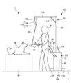
- the irradiation target is a dog and the periodontal tissue of the dog is treated will be described as an example.
- a user P such as a veterinarian, places a dog D on a table 150 arranged on an installation surface S, for example. At this time, the mouth of the dog D is kept open.
- the user P holds the irradiation device 10 and presses the operation switch 9 of the irradiation device 10. Then, electricity and a gas for plasma generation are supplied from the supply unit 20 and the supply source 70 to the irradiation device 10 via the power / gas supply line 30.
- the plasma generating gas supplied to the irradiation device 10 flows into the inner space of the tubular dielectric 3 from the rear end of the tubular dielectric 3 of the plasma generator 12.
- the plasma generating gas is ionized at a position where the internal electrode 4 and the external electrode 5 face each other, and plasma is generated.
- the internal electrode 4 and the external electrode 5 face each other in a direction orthogonal to the direction in which the plasma generating gas flows.
- Plasma generated at a position where the outer peripheral surface of the internal electrode 4 and the inner peripheral surface of the external electrode 5 face each other flows through the gas flow path 6 and the active gas flow path 7 in this order.
- the plasma flows while changing the gas composition, and an active gas containing active species such as radicals is generated by the plasma.
- the irradiation device 10 discharges plasma and active gas (hereinafter, referred to as plasma or the like) from the active gas channel 7 to the outside.
- the user P puts the tip of the irradiation device 10 into the mouth of the dog D, and makes the tip of the irradiation device 10 face the periodontal tissue.
- the treatment is performed by applying plasma or the like to a predetermined portion of the periodontal tissue for a certain period of time. After the treatment of a predetermined part is completed, plasma or the like is applied to another part of the periodontal tissue for a certain time. Thus, the treatment is performed over the entire periodontal tissue in the mouth of the dog D.
- the user P holding the irradiation device 10 drops the irradiation device 10 from the hand for some reason. Even in this case, the irradiation device 10 is fixed to the support portion 100 via the wire 90. For this reason, as shown in FIG. 5, even if the user P releases his / her hand from the irradiation device, the irradiation device 10 is less likely to fall on the installation surface S.
- the irradiation tool 10 when operating the irradiation tool 10 that is not fixed to the support portion 100 via the wire 90, it may be difficult to keep the irradiation tool 10 at a desired position, but in this embodiment, Since the irradiation tool 10 is fixed to the support portion 100 via the wire 90, there is also an advantage that the irradiation tool 10 can be easily held at a desired position. This means that the plasma or the like can be more reliably applied to a predetermined part of the affected part, which can greatly affect the therapeutic effect.
- the support section 100 includes a housing section 111.
- the wire 90 is wound into the housing portion 111.
- the wire 90 is unwound from the housing portion 111. be able to. In this way, the length of the wire 90 protruding outside from the housing 111 can be adjusted.
- the height L1 of the portion of the roller 115 where the end portion (B) of the wire 90 is fixed from the installation surface S (the floor or the ground) is larger than the length L2 of the wire 90. Therefore, when the user P holding the irradiation device 10 drops the irradiation device 10 from his / her hand, the falling irradiation device 10 can be prevented from contacting the installation surface S.
- FIG. 6 the same components as those in FIGS. 1 to 5 for describing the active gas irradiation apparatus of the first embodiment are denoted by the same reference numerals, and description thereof will be omitted.
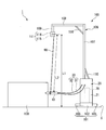
- a power / gas supply line 30 is provided on the upper surface of the supply unit 20 so as to extend upward.
- a gas pipe and electric wiring are collectively accommodated.
- the support portion 100 is configured by a flexible rod 116 provided on the upper surface of the supply unit 20 so as to extend upward, and a fixture 117 having a rotating portion.
- the distal end of the flexible rod 116 is fixed to the power / gas supply line 30 by a binding band 90 as a connecting member, and the root end of the flexible rod 116 is connected to the rotating part of the fixture 117.
- the rotating portion is rotatable in the vertical direction, and is configured to be fixed when the angle of the flexible rod 116 becomes a predetermined angle.
- the flexible rod 116 may be directly fixed to the upper surface of the supply unit 20 without using the fixing tool 117.
- the binding band 90 as a connecting member is not particularly limited as long as the power / gas supply line 30 can be fixed to the distal end portion of the flexible rod 116 without excessively compressing the gas flow path.
- a well-known resin binding band or the like can be used.
- the binding band 90 is made of a metal wire, resin, or metal figure eight ring (which can be fixed in a state where the flexible rod 116 and the power / gas supply line 30 are passed through two holes, respectively). It may be.
- the flexible rod 116 and the binding band 90 hold the middle part of the power / gas supply line 30 at a sufficient height, so that the irradiation device 10 can be prevented from dropping.
- the flexible rod 116 is fixed to the power / gas supply line 30 by the binding band 90 even at a portion other than the tip portion.
- the number of fixing portions other than the tip portion is 3 to 10.
- the power / gas supply line 30 is fixed at a position other than the distal end of the flexible rod 116, the interval between the adjacent fixed positions is 10 cm to 50 cm for a plurality of fixing positions including the distal end. Preferably, it is more preferably 15 cm to 40 cm.
- a member formed of a resin (FRP or CFRP) reinforced with a fiber such as carbon or glass can be used.
- the tip of the flexible rod 116 fixed to the power / gas supply line 30 is higher than the upper surface of the supply unit 20. It is configured to be arranged at a high position.
- the length L2 of the flexible rod 116 is larger than the difference (L3-L4) between the length L3 of the power / gas supply line 30 and the height L4 of the supply unit 20, ie, It is preferable to satisfy the relationship of L2> (L3-L4).
- the difference between the value of L2 and the value of (L3-L4) is determined from the viewpoint of more reliably preventing the user from dropping the irradiation device 10 during use, while ensuring the operability of the irradiation device 10 well.
- the physical properties such as the thickness and elastic modulus of the flexible rod 116 are not particularly limited.
- the height of the distal end of the flexible rod 116 from the upper surface of the supply unit 20 is preferably 10 cm to 10 cm.
- the thickness and physical properties that can be maintained at 100 cm, more preferably about 20 cm to 50 cm may be appropriately selected.
- a holder 22 for holding the irradiation device 10 is further provided on the upper surface of the supply unit 20.
- the holder 22 may also have a configuration in which a rotating portion is provided similarly to the fixing tool 117 so that the holding angle of the irradiation device 10 can be adjusted. Also in this case, it is preferable that the holding angle is fixed at a predetermined angle by a thumb screw or the like.
- the operation panel 23 is provided in front of the upper surface of the supply unit 20.
- the operation panel 23 is connected to the control unit 80, and is configured to adjust the flow rate of the plasma generating gas from the operation panel 23 via the control unit 80.
- the operation panel 23 may be provided with an on / off switch and a standby switch of the supply unit 20, a flow rate display portion of the plasma generating gas, and the like.
- a foot switch holder 27 in which a foot switch 120 is installed is provided at a lower front part of the supply unit 20.
- the foot switch holder 27 is configured to be detachable.
- the foot switch 120 may be operated while the foot switch holder 27 is installed at the lower front part of the supply unit 20, or the foot switch 120 may be operated by removing the foot switch holder 27 and moving it to a desired position. .
- the foot switch holder 27 can be moved by grasping the grip portion 28 of the foot switch holder 27.
- the foot switch 27 can be assigned the same function as the operation switch 9.
- a known switch can be appropriately used, and specific examples include “MKF-MED” manufactured by Nippon Steute.
- a caster 29 is provided at the bottom of the supply unit 20 so that it can be easily moved.
- the casters 29 preferably have a lock / unlock mechanism.
- Known casters can be employed as the casters 29.
- grip portions 24 and 25 are provided, respectively. When the active gas irradiation device 1 is moved, the active gas irradiation device 1 can be moved by holding the grip portions 24 and 25.
- the power / gas supply line 30 is provided on the upper surface of the supply unit 20 so as to extend upward, the power / gas supply line is provided. Damage or the like caused by the contact of the 30 with a wall or the like is suppressed.
- the flexible rod-shaped body 116 ensures the operability of the active gas irradiation device 1 with a simple configuration while maintaining the entire size of the active gas irradiation device 1 compact while the user is in use. The effect of the present invention of preventing the irradiation device from dropping at the same time can be achieved.
- the active gas irradiation device 1 is a device having a configuration suitable for movement and transportation. Further, the supply unit 20 is configured so that the back cover thereof can be removed by holding the handle portion 26 and the inside of the supply unit 20 can be accessed.
- the active gas irradiation device 1 may not include the storage unit 111, and the second end of the wire 90 may be directly fixed to the lower end of the second vertical frame 109.
- the linear member may be formed of an elastic material such as a helical spring. The spring constant of the linear member may be set so that the linear member does not come into contact with the installation surface S even if the linear member extends under the load of the irradiation device 10 and the power / gas supply line 30.
- the irradiation device 10 may be configured to discharge only one of the plasma and the active gas.
- the first end of the wire 90 may be configured to be fixed to at least one of the gas tube 31 and the electric wiring 32 that is the power / gas supply line 30.
- the first end of the wire 90 may be configured to be fixed to at least one of the gas pipe 31 and the electric wiring 32 and the irradiation device 10.
- the plasma irradiation device may be used for humans and non-human animals, or the plasma irradiation device may be used only for non-human animals.
- the plasma irradiation device described above can be suitably used for applications such as treatment of animals and humans, beauty treatment, and the like.
- Active gas irradiation device (plasma irradiation device) DESCRIPTION OF SYMBOLS 10 Irradiation apparatus 12 Plasma generation part 30 Power / gas supply line 90 Connecting member 100 Support part 111 Housing part L1 Height from installation surface L2 Length of linear member S Installation surface (floor surface or ground)
Abstract
This plasma irradiation apparatus is provided with: an irradiation instrument which has a plasma generation part and which discharges plasma generated by the plasma generation part and/or an active gas generated by the plasma; a supply unit which supplies electricity and a gas for plasma generation to the irradiation instrument; a support part which extends upward from the supply unit; an electricity/gas supply line which connects the irradiation instrument and the supply unit; and a connection member which connects the support part with the irradiation instrument and/or the electricity/gas supply line. The irradiation instrument is retained, by the support part and the connection member, at a position higher than the installation plane of the supply unit.
Description
本発明は、プラズマ照射装置に関する。
The present invention relates to a plasma irradiation device.
従来、例えば、歯科治療等の医療を用途とするプラズマ照射装置が知られている。
プラズマ照射装置は、創傷等の患部にプラズマ又は活性ガスを照射することで、患部を治癒する。前記活性ガスは、プラズマ照射装置内でプラズマによって発生させられる。 2. Description of the Related Art Conventionally, for example, a plasma irradiation apparatus for medical use such as dental treatment is known.
The plasma irradiation device cures an affected part such as a wound by irradiating the affected part with plasma or active gas. The active gas is generated by plasma in a plasma irradiation device.
例えば、特許文献1は、歯科治療を行うプラズマジェット照射装置を開示している。前記プラズマジェット照射装置は、プラズマジェット照射手段を有する照射器具を備えている。前記プラズマジェット照射装置は、発生したプラズマと、活性種と、を被照射物に照射する。前記活性種は、プラズマ中の気体又はプラズマ周辺の気体とプラズマとが反応して生成される。
特許文献2は、照射器具内部で活性ガス(活性種)を発生させ、その活性ガスをノズルから吐出して患部に照射するプラズマ照射装置を開示している。前記活性ガスは、例えば、活性酸素や活性窒素等である。 For example,Patent Literature 1 discloses a plasma jet irradiation apparatus for performing dental treatment. The plasma jet irradiation apparatus includes an irradiation device having plasma jet irradiation means. The plasma jet irradiation device irradiates the object to be irradiated with the generated plasma and the active species. The active species are generated by a reaction between a gas in the plasma or a gas around the plasma and the plasma.
Patent Literature 2 discloses a plasma irradiation apparatus that generates an active gas (active species) inside an irradiation tool, discharges the active gas from a nozzle, and irradiates an affected part with the gas. The active gas is, for example, active oxygen or active nitrogen.
特許文献2は、照射器具内部で活性ガス(活性種)を発生させ、その活性ガスをノズルから吐出して患部に照射するプラズマ照射装置を開示している。前記活性ガスは、例えば、活性酸素や活性窒素等である。 For example,
Patent Literature 2 discloses a plasma irradiation apparatus that generates an active gas (active species) inside an irradiation tool, discharges the active gas from a nozzle, and irradiates an affected part with the gas. The active gas is, for example, active oxygen or active nitrogen.
しかしながら、この種のプラズマ照射装置では、使用者が治療中に、照射器具が床等に落下させたりすることがある。このような落下は照射器具の破損や故障につながるおそれがあるため望ましくない。一方、このような落下を防止するために照射器具の移動可能範囲を強く制約してしまうと、照射器具の操作性に劣る結果となる場合がある。従って、照射器具の操作性を確保しつつ、照射器具の落下を防止するための改善が望まれている。
However, in this type of plasma irradiation apparatus, the irradiation tool may drop on the floor or the like during the treatment by the user. Such a drop is not desirable because it may lead to damage or failure of the irradiation device. On the other hand, if the movable range of the irradiation tool is strongly restricted in order to prevent such a fall, the operability of the irradiation tool may be poor. Therefore, there is a need for an improvement for preventing the irradiation device from falling while ensuring the operability of the irradiation device.
本発明は、このような問題点に鑑みてなされたものであって、照射器具の操作性を確保しつつ、使用中に使用者が照射器具を落下させることを抑制したプラズマ照射装置を提供することを目的とする。
The present invention has been made in view of such a problem, and provides a plasma irradiation apparatus that suppresses a user from dropping an irradiation tool during use while ensuring operability of the irradiation tool. The purpose is to:
上記課題を解決するために、この発明は以下の手段を提案している。
本発明のプラズマ照射装置は、プラズマ発生部を有し、前記プラズマ発生部にて発生したプラズマ及び前記プラズマによって生じる活性ガスの少なくとも一方を吐出する照射器具と、前記照射器具に電力及びプラズマ発生用ガスを供給する供給ユニットと、前記供給ユニットから上方向に延びる支持部と、前記照射器具と供給ユニットとを連結する電力/ガス供給ラインと、前記照射器具及び前記電力/ガス供給ラインの少なくとも一方と前記支持部とを連結する連結部材と、を備えるプラズマ照射装置であって、前記支持部及び前記連結材により、前記照射器具が、前記供給ユニットの設置面よりも上方の位置に維持されることを特徴としている。 In order to solve the above problems, the present invention proposes the following means.
The plasma irradiation apparatus of the present invention has a plasma generation unit, an irradiation device for discharging at least one of plasma generated in the plasma generation unit and an active gas generated by the plasma, and a power and plasma generation device for the irradiation device. A supply unit for supplying gas, a support extending upward from the supply unit, a power / gas supply line connecting the irradiation device and the supply unit, and at least one of the irradiation device and the power / gas supply line And a connecting member for connecting the supporting unit and the supporting unit, wherein the supporting unit and the connecting member maintain the irradiation device at a position above the installation surface of the supply unit. It is characterized by:
この発明によれば、例えば、照射器具を手に持っている使用者が手から照射器具を落としたときに、照射器具及び電力/ガス供給ラインの少なくとも一方は、連結部材を介して支持部に固定されている。このため、使用者が照射器具から手を放しても、照射器具の下方への移動が制限され、使用中に使用者が照射器具を落下するのを防止することができる。更に、上記支持部への固定は、連結部材を介しているため、照射器具を操作する際における下方以外の方向への照射器具の移動の自由は適度に確保される。従って、プラズマ照射装置の操作性も良好に確保される。
According to the present invention, for example, when a user holding the irradiation device drops the irradiation device from the hand, at least one of the irradiation device and the power / gas supply line is connected to the support portion via the connecting member. Fixed. For this reason, even if the user releases his hand from the irradiation device, the downward movement of the irradiation device is restricted, and the user can be prevented from falling down during use. Furthermore, since the fixing to the support portion is via the connecting member, the freedom of movement of the irradiation tool in a direction other than below when operating the irradiation tool is appropriately secured. Therefore, the operability of the plasma irradiation device is also well ensured.
また、上記のプラズマ照射装置において、前記連結部材は線状部材であって、 前記線状部材の一端(A)が前記照射器具及び前記電力/ガス供給ラインの少なくとも一方に固定され、前記線状部材の他端(B)が前記支持部に固定され、前記支持部は、前記線状部材を巻き込み可能、かつ、前記線状部材を巻き出し可能な収容部を有してもよい。
この発明によれば、線状部材の長さが比較的長く必要でない場合には、線状部材を収容部に巻き込ませ、線状部材の長さが比較的長く必要な場合には、線状部材を収容部から巻き出させることができる。このようにして、収容部から外部に突出する線状部材の長さを調節することができる。 In the above plasma irradiation apparatus, the connecting member is a linear member, and one end (A) of the linear member is fixed to at least one of the irradiation device and the power / gas supply line, The other end (B) of the member may be fixed to the support portion, and the support portion may have a housing portion that can wind the linear member and can unwind the linear member.
According to the present invention, when the length of the linear member is not relatively long, the linear member is rolled into the housing portion, and when the length of the linear member is relatively long, the linear member is The member can be unwound from the housing. In this way, it is possible to adjust the length of the linear member protruding from the housing to the outside.
また、上記のプラズマ照射装置において、前記線状部材の一端(A)は、前記照射器具に固定され、前記支持部における前記線状部材の他端(B)が固定された箇所が、前記一端(A)より高い位置に配置され、前記線状部材の長さは、前記他端(B)が固定された箇所の床面又は地面からの高さよりも小さくてもよい。この発明によれば、照射器具を手に持っている使用者が手から照射器具を落としたときに、落下する照射器具が床面や地面(前記供給ユニットの設置面)に接触するのを防止することができる。
また、上記のプラズマ照射装置において、前記支持部材が、可撓性棒状体を含み、前記連結部材が、可撓性棒状体と前記電力/ガス供給ラインとを固定する結束帯であり、前記電力/ガス供給ライン及び前記可撓性棒状体が、それぞれ前記供給ユニットの上面に、上方向に向かって伸びるよう配置され、前記電力/ガス供給ラインの中間部が、前記結束帯により可撓性棒状体に固定されていることにより、前記電力/ガス供給ラインの中間部が、前記供給ユニットの上面よりも高い位置に維持されていても良い。
この発明によれば、供給ユニットの上面に、上方向に延びるよう電力/ガス供給ラインが設けられているため、電力/ガス供給ラインが壁等に接触することによる破損等が抑制される。また、可撓性棒状体により、簡易な構成で、かつ、活性ガス照射装置全体のサイズをコンパクトに維持したまま、活性ガス照射装置の操作性を確保しつつ、使用者が使用中に照射器具を落下させることを防止することができる。 Further, in the above plasma irradiation apparatus, one end (A) of the linear member is fixed to the irradiation device, and the other end (B) of the linear member in the support portion is fixed to the one end. (A) It is arrange | positioned at a higher position and the length of the said linear member may be smaller than the height from the floor surface or the ground of the location to which the said other end (B) was fixed. ADVANTAGE OF THE INVENTION According to this invention, when the user who holds an irradiation apparatus drops an irradiation apparatus from a hand, it prevents the falling irradiation apparatus from contacting a floor surface or the ground (the installation surface of the supply unit). can do.
Further, in the plasma irradiation apparatus described above, the support member includes a flexible rod, and the connecting member is a binding band for fixing the flexible rod and the power / gas supply line. A gas supply line and the flexible rod are disposed on the upper surface of the supply unit so as to extend upward, and an intermediate portion of the power / gas supply line is formed of a flexible rod by the binding band. By being fixed to the body, an intermediate portion of the power / gas supply line may be maintained at a position higher than the upper surface of the supply unit.
According to the present invention, since the power / gas supply line is provided on the upper surface of the supply unit so as to extend upward, damage due to the power / gas supply line coming into contact with a wall or the like is suppressed. In addition, the flexible rod-shaped body has a simple configuration, and the operability of the active gas irradiation device is ensured while maintaining the compact size of the active gas irradiation device as a whole. Can be prevented from dropping.
また、上記のプラズマ照射装置において、前記プラズマ発生部は、誘電体バリア放電により前記プラズマを発生してもよい。
また、上記のプラズマ照射装置において、前記プラズマ発生部は、窒素ガスを用いて前記プラズマを発生してもよい。 Further, in the above plasma irradiation apparatus, the plasma generation unit may generate the plasma by dielectric barrier discharge.
In the above plasma irradiation apparatus, the plasma generation unit may generate the plasma using nitrogen gas.
本発明のプラズマ照射装置によれば、照射器具の操作性を確保しつつ、使用者が使用中に照射器具を落下させることを防止することができる。
According to the plasma irradiation apparatus of the present invention, it is possible to prevent the user from dropping the irradiation tool during use while ensuring the operability of the irradiation tool.
(第一実施形態)
以下、本発明に係るプラズマ照射装置の第一実施形態を、図1から図5を参照しながら説明する。
本実施形態のプラズマ照射装置は、プラズマジェット照射装置又は活性ガス照射装置である。
プラズマジェット照射装置は、プラズマを発生させる。プラズマジェット照射装置は、発生したプラズマと、活性種と、を被照射者(被照射物)に直接照射する。前記活性種は、プラズマ中の気体又はプラズマ周辺の気体とプラズマとが反応して生成される。活性種としては、活性酸素種や活性窒素種を例示できる。活性酸素種としては、ヒドロキシルラジカル、一重項酸素、オゾン、過酸化水素、スーパーオキシドアニオンラジカル等を例示できる。活性窒素種としては、一酸化窒素、二酸化窒素、ペルオキシナイトライト、過酸化亜硝酸、三酸化二窒素等を例示できる。
一方で、活性ガス照射装置は、プラズマを発生させ、前記プラズマによって生じる活性種を含む活性ガスを被照射者に照射する。前記活性種は、プラズマ中の気体又はプラズマ周辺の気体とプラズマとが反応して生成される。
以下、プラズマ照射装置が活性ガス照射装置である場合を例にとって説明する。 (First embodiment)
Hereinafter, a first embodiment of a plasma irradiation apparatus according to the present invention will be described with reference to FIGS.
The plasma irradiation device of the present embodiment is a plasma jet irradiation device or an active gas irradiation device.
The plasma jet irradiation device generates plasma. The plasma jet irradiation device directly irradiates the generated plasma and active species to an irradiation target (object to be irradiated). The active species are generated by a reaction between a gas in the plasma or a gas around the plasma and the plasma. Examples of the active species include active oxygen species and active nitrogen species. Examples of the active oxygen species include a hydroxyl radical, singlet oxygen, ozone, hydrogen peroxide, and a superoxide anion radical. Examples of the active nitrogen species include nitric oxide, nitrogen dioxide, peroxynitrite, nitrous oxide, nitrous oxide and the like.
On the other hand, the active gas irradiation device generates plasma and irradiates an irradiation target with an active gas containing active species generated by the plasma. The active species are generated by a reaction between a gas in the plasma or a gas around the plasma and the plasma.
Hereinafter, a case where the plasma irradiation device is an active gas irradiation device will be described as an example.
図1及び図2に示すように、本実施形態の活性ガス照射装置1は、照射器具10と、供給ユニット20と、電力/ガス供給ライン30と、供給源70と、制御部80と、ワイヤ(線状部材)90と、支持部100と、を備える。
照射器具10は、照射器具10内で発生した活性ガスを吐出する。
供給ユニット20は、照射器具10に電力及びプラズマ発生用ガスを供給する。プラズマ発生用ガスとしては、例えば、ヘリウム、ネオン、アルゴン、クリプトン等の希ガス;窒素(窒素ガス);等を例示できる。これらのガスは、1種単独で供給されてもよいし、2種以上を組み合わせて供給されてもよい。
プラズマ発生用ガスは、窒素を主成分とすることが好ましい。ここで、窒素を主成分とするとは、プラズマ発生用ガスにおける窒素の含有量が50体積%超であることをいう。 As shown in FIGS. 1 and 2, the activegas irradiation device 1 of the present embodiment includes an irradiation device 10, a supply unit 20, a power / gas supply line 30, a supply source 70, a control unit 80, a wire (Linear member) 90 and a support portion 100.
Theirradiation device 10 discharges the active gas generated in the irradiation device 10.
Thesupply unit 20 supplies power and a gas for plasma generation to the irradiation device 10. Examples of the plasma generation gas include rare gases such as helium, neon, argon, and krypton; and nitrogen (nitrogen gas). These gases may be supplied alone or in combination of two or more.
The plasma generating gas preferably contains nitrogen as a main component. Here, “mainly containing nitrogen” means that the content of nitrogen in the plasma generating gas is more than 50% by volume.
照射器具10は、照射器具10内で発生した活性ガスを吐出する。
供給ユニット20は、照射器具10に電力及びプラズマ発生用ガスを供給する。プラズマ発生用ガスとしては、例えば、ヘリウム、ネオン、アルゴン、クリプトン等の希ガス;窒素(窒素ガス);等を例示できる。これらのガスは、1種単独で供給されてもよいし、2種以上を組み合わせて供給されてもよい。
プラズマ発生用ガスは、窒素を主成分とすることが好ましい。ここで、窒素を主成分とするとは、プラズマ発生用ガスにおける窒素の含有量が50体積%超であることをいう。 As shown in FIGS. 1 and 2, the active
The
The
The plasma generating gas preferably contains nitrogen as a main component. Here, “mainly containing nitrogen” means that the content of nitrogen in the plasma generating gas is more than 50% by volume.
供給ユニット20は、供給源70を収容している。供給源70は、プラズマ発生用ガスを収容している。供給ユニット20は、例えば、100Vの家庭用電源等の電源(不図示)と接続される。
電力/ガス供給ライン30は、ガス管31と、電気配線32と、を備えている。
ガス管31は、照射器具10と供給ユニット20とを連結している。電気配線32は、照射器具10と供給ユニット20とを連結している。
本実施形態において、ガス管31と電気配線32とは、各々独立しているが、ガス管31と電気配線32とは一体でもよい。 Thesupply unit 20 contains a supply source 70. The supply source 70 contains a plasma generating gas. The supply unit 20 is connected to a power supply (not shown) such as a household power supply of 100 V, for example.
The power /gas supply line 30 includes a gas pipe 31 and an electric wiring 32.
Thegas pipe 31 connects the irradiation device 10 and the supply unit 20. The electric wiring 32 connects the irradiation device 10 and the supply unit 20.
In the present embodiment, thegas pipe 31 and the electric wiring 32 are independent of each other, but the gas pipe 31 and the electric wiring 32 may be integrated.
電力/ガス供給ライン30は、ガス管31と、電気配線32と、を備えている。
ガス管31は、照射器具10と供給ユニット20とを連結している。電気配線32は、照射器具10と供給ユニット20とを連結している。
本実施形態において、ガス管31と電気配線32とは、各々独立しているが、ガス管31と電気配線32とは一体でもよい。 The
The power /
The
In the present embodiment, the
図3は、照射器具10における軸線に沿う面の断面(縦断面)図である。
図3に示すように、照射器具10は、長尺状のカウリング11と、カウリング11内に位置するプラズマ発生部12と、を備える。
カウリング11は、円筒形の胴体部11bと、胴体部11bの先端を塞ぐヘッド部11aとを備える。なお、胴体部11bは、円筒形に限らず、四角筒、六角筒、八角筒等の多角筒形でもよい。 FIG. 3 is a cross-sectional (longitudinal) view of a plane along the axis of theirradiation device 10.
As shown in FIG. 3, theirradiation device 10 includes a long cowling 11 and a plasma generation unit 12 located in the cowling 11.
Thecowling 11 includes a cylindrical body 11b and a head 11a that closes a tip of the body 11b. The body 11b is not limited to a cylindrical shape, but may be a polygonal cylindrical shape such as a square tube, a hexagonal tube, and an octagonal tube.
図3に示すように、照射器具10は、長尺状のカウリング11と、カウリング11内に位置するプラズマ発生部12と、を備える。
カウリング11は、円筒形の胴体部11bと、胴体部11bの先端を塞ぐヘッド部11aとを備える。なお、胴体部11bは、円筒形に限らず、四角筒、六角筒、八角筒等の多角筒形でもよい。 FIG. 3 is a cross-sectional (longitudinal) view of a plane along the axis of the
As shown in FIG. 3, the
The
ヘッド部11aは、先端に向かい漸次窄んでいる。即ち、本実施形態におけるヘッド部11aは、円錐形である。なお、ヘッド部11aは、円錐形に限らず、四角錘、六角錘、八角錘等の多角錘形でもよい。
ヘッド部11aは、管軸O1方向に延びる活性ガス流路7を内部に有している。管軸O1は、胴体部11bの管軸である。
ヘッド部11aの材料は、特に制限はなく、絶縁性を有してもよいし、絶縁性を有しなくてもよい。ヘッド部11aの材料は、耐摩耗性、耐腐食性に優れる材料が好ましい。耐摩耗性、耐腐食性に優れる材料としては、ステンレス等の金属を例示できる。 Thehead 11a is gradually narrowed toward the tip. That is, the head 11a in the present embodiment has a conical shape. The head 11a is not limited to a conical shape, and may be a polygonal pyramid such as a quadrangular pyramid, a hexagonal pyramid, or an octagonal pyramid.
Thehead 11a has an active gas flow path 7 extending in the direction of the tube axis O1 therein. The tube axis O1 is the tube axis of the body 11b.
The material of thehead 11a is not particularly limited, and may have insulating properties or may not have insulating properties. The material of the head portion 11a is preferably a material having excellent wear resistance and corrosion resistance. As a material having excellent wear resistance and corrosion resistance, a metal such as stainless steel can be exemplified.
ヘッド部11aは、管軸O1方向に延びる活性ガス流路7を内部に有している。管軸O1は、胴体部11bの管軸である。
ヘッド部11aの材料は、特に制限はなく、絶縁性を有してもよいし、絶縁性を有しなくてもよい。ヘッド部11aの材料は、耐摩耗性、耐腐食性に優れる材料が好ましい。耐摩耗性、耐腐食性に優れる材料としては、ステンレス等の金属を例示できる。 The
The
The material of the
胴体部11bの材料は、特に制限はないが、絶縁性を有する材料が好ましい。胴体部11bは、電気絶縁性の材料のみで形成されてもよいし、電気絶縁性の材料とその表面に金属材料の層を有する多層構造でもよい。
絶縁性の材料としては、熱可塑性樹脂、熱硬化性樹脂等を例示できる。熱可塑性樹脂としては、ポリエチレン、ポリプロピレン、ポリ塩化ビニル、ポリスチレン、アクリロニトリル-ブタジエン-スチレン樹脂(ABS樹脂)等を例示できる。熱硬化性樹脂としては、フェノール樹脂、メラミン樹脂、ユリア樹脂、エポキシ樹脂、不飽和ポリエステル樹脂、シリコン樹脂等を例示できる。
金属材料としては、ステンレス、チタン、アルミニウム等が挙げられる。
胴体部11bとヘッド部11aとの材料は、同じでもよく、異なってもよい。
胴体部11bの大きさは、特に制限はなく、手指で把持しやすい大きさとすることができる。
胴体部11bは、外周面に操作スイッチ9(操作部)を備えている。なお、操作スイッチ9は、照射器具10に設けられず、供給ユニット20に設けられたり、フットスイッチとして設けられたりしてもよい。 The material of thebody 11b is not particularly limited, but is preferably a material having an insulating property. The body 11b may be formed of only an electrically insulating material, or may have a multilayer structure having an electrically insulating material and a metal material layer on its surface.
Examples of the insulating material include a thermoplastic resin and a thermosetting resin. Examples of the thermoplastic resin include polyethylene, polypropylene, polyvinyl chloride, polystyrene, acrylonitrile-butadiene-styrene resin (ABS resin) and the like. Examples of the thermosetting resin include a phenol resin, a melamine resin, a urea resin, an epoxy resin, an unsaturated polyester resin, and a silicone resin.
Examples of the metal material include stainless steel, titanium, and aluminum.
The material of thebody 11b and the material of the head 11a may be the same or different.
The size of thebody 11b is not particularly limited, and may be a size that can be easily grasped with fingers.
Thebody 11b has an operation switch 9 (operation unit) on the outer peripheral surface. Note that the operation switch 9 may not be provided on the irradiation device 10 but may be provided on the supply unit 20 or may be provided as a foot switch.
絶縁性の材料としては、熱可塑性樹脂、熱硬化性樹脂等を例示できる。熱可塑性樹脂としては、ポリエチレン、ポリプロピレン、ポリ塩化ビニル、ポリスチレン、アクリロニトリル-ブタジエン-スチレン樹脂(ABS樹脂)等を例示できる。熱硬化性樹脂としては、フェノール樹脂、メラミン樹脂、ユリア樹脂、エポキシ樹脂、不飽和ポリエステル樹脂、シリコン樹脂等を例示できる。
金属材料としては、ステンレス、チタン、アルミニウム等が挙げられる。
胴体部11bとヘッド部11aとの材料は、同じでもよく、異なってもよい。
胴体部11bの大きさは、特に制限はなく、手指で把持しやすい大きさとすることができる。
胴体部11bは、外周面に操作スイッチ9(操作部)を備えている。なお、操作スイッチ9は、照射器具10に設けられず、供給ユニット20に設けられたり、フットスイッチとして設けられたりしてもよい。 The material of the
Examples of the insulating material include a thermoplastic resin and a thermosetting resin. Examples of the thermoplastic resin include polyethylene, polypropylene, polyvinyl chloride, polystyrene, acrylonitrile-butadiene-styrene resin (ABS resin) and the like. Examples of the thermosetting resin include a phenol resin, a melamine resin, a urea resin, an epoxy resin, an unsaturated polyester resin, and a silicone resin.
Examples of the metal material include stainless steel, titanium, and aluminum.
The material of the
The size of the
The
図3及び図4に示すように、プラズマ発生部12は、管状誘電体3(誘電体)と、内部電極4と、外部電極5とを備える。
管状誘電体3は、管軸O1方向に延びる円筒状の部材である。管状誘電体3は、管軸O1方向に延びるガス流路6を内部に有している。活性ガス流路7とガス流路6とは連通している。なお、管軸O1は、管状誘電体3の管軸と同じである。
管状誘電体3の材料としては、公知のプラズマ装置に使用する誘電体材料を適用できる。管状誘電体3の材料としては、例えば、ガラス、セラミックス、合成樹脂等を例示できる。管状誘電体3の誘電率は低いほど好ましい。 As shown in FIGS. 3 and 4, theplasma generator 12 includes a tubular dielectric 3 (dielectric), an internal electrode 4, and an external electrode 5.
Thetubular dielectric 3 is a cylindrical member extending in the tube axis O1 direction. The tubular dielectric 3 has therein a gas flow path 6 extending in the direction of the tube axis O1. The active gas passage 7 and the gas passage 6 communicate with each other. Note that the tube axis O1 is the same as the tube axis of the tubular dielectric 3.
As a material of thetubular dielectric 3, a dielectric material used for a known plasma device can be applied. Examples of the material of the tubular dielectric 3 include glass, ceramics, and synthetic resin. The lower the dielectric constant of the tubular dielectric 3, the better.
管状誘電体3は、管軸O1方向に延びる円筒状の部材である。管状誘電体3は、管軸O1方向に延びるガス流路6を内部に有している。活性ガス流路7とガス流路6とは連通している。なお、管軸O1は、管状誘電体3の管軸と同じである。
管状誘電体3の材料としては、公知のプラズマ装置に使用する誘電体材料を適用できる。管状誘電体3の材料としては、例えば、ガラス、セラミックス、合成樹脂等を例示できる。管状誘電体3の誘電率は低いほど好ましい。 As shown in FIGS. 3 and 4, the
The
As a material of the
管状誘電体3は、内部に内部電極4を備えている。内部電極4は、管軸O1方向に延びる略円柱状の部材である。内部電極4は、管状誘電体3の内面と離間している。
内部電極4は、管軸O1方向に延びる軸部と、軸部の外周面のねじ山とを備える。軸部は、中実でもよいし、中空でもよい。中でも、軸部は中実が好ましい。軸部が中実であれば、加工が容易であり、かつ機械的な耐久性を高められる。
内部電極4のねじ山は、軸部の周方向に周回する螺旋状のねじ山である。内部電極4の形態は、雄ねじと同様の形態である。
内部電極4は、外周面にねじ山を有することにより、ねじ山先端部の電界が局所的に強くなり、放電開始電圧が低くなる。このため、低電力でプラズマを生成し、維持できる。
なお、内部電極4は、外周面にねじ山等の凹凸を有しなくてもよい。即ち、内部電極4は、外周面に凹凸を有しない円柱の部材でもよい。 Thetubular dielectric 3 has an internal electrode 4 inside. The internal electrode 4 is a substantially columnar member extending in the tube axis O1 direction. The internal electrode 4 is separated from the inner surface of the tubular dielectric 3.
Theinternal electrode 4 includes a shaft portion extending in the tube axis O1 direction, and a thread on the outer peripheral surface of the shaft portion. The shaft may be solid or hollow. Above all, the shaft is preferably solid. If the shaft portion is solid, processing is easy and mechanical durability can be enhanced.
The screw thread of theinternal electrode 4 is a spiral screw thread orbiting in the circumferential direction of the shaft portion. The form of the internal electrode 4 is the same as that of the male screw.
Since theinternal electrode 4 has a thread on the outer peripheral surface, the electric field at the tip of the thread is locally increased, and the firing voltage is reduced. Therefore, plasma can be generated and maintained with low power.
Theinternal electrode 4 does not need to have unevenness such as a thread on the outer peripheral surface. That is, the internal electrode 4 may be a cylindrical member having no irregularities on the outer peripheral surface.
内部電極4は、管軸O1方向に延びる軸部と、軸部の外周面のねじ山とを備える。軸部は、中実でもよいし、中空でもよい。中でも、軸部は中実が好ましい。軸部が中実であれば、加工が容易であり、かつ機械的な耐久性を高められる。
内部電極4のねじ山は、軸部の周方向に周回する螺旋状のねじ山である。内部電極4の形態は、雄ねじと同様の形態である。
内部電極4は、外周面にねじ山を有することにより、ねじ山先端部の電界が局所的に強くなり、放電開始電圧が低くなる。このため、低電力でプラズマを生成し、維持できる。
なお、内部電極4は、外周面にねじ山等の凹凸を有しなくてもよい。即ち、内部電極4は、外周面に凹凸を有しない円柱の部材でもよい。 The
The
The screw thread of the
Since the
The
内部電極4の材料は、導電材であれば特に制限はなく、公知のプラズマ装置の電極に使用できる金属を適用できる。内部電極4の材料としては、ステンレス、銅、タングステン等の金属、カーボン等を例示できる。
材料 The material of the internal electrode 4 is not particularly limited as long as it is a conductive material, and a metal that can be used for an electrode of a known plasma device can be applied. Examples of the material of the internal electrode 4 include metals such as stainless steel, copper, and tungsten, and carbon.
管状誘電体3の外周面の一部には、内部電極4に沿う外部電極5を備えている。外部電極5は、管状誘電体3の外周面に沿って周回する環状の電極である。
外部電極5の材料は、導電材であれば特に制限はなく、公知のプラズマ装置の電極に使用する金属を適用できる。外部電極5の材料としては、ステンレス、銅、タングステン等の金属、カーボン等を例示できる。 Anexternal electrode 5 along the internal electrode 4 is provided on a part of the outer peripheral surface of the tubular dielectric 3. The external electrode 5 is an annular electrode that goes around the outer peripheral surface of the tubular dielectric 3.
The material of theexternal electrode 5 is not particularly limited as long as it is a conductive material, and a metal used for an electrode of a known plasma device can be applied. Examples of the material of the external electrode 5 include metals such as stainless steel, copper, and tungsten, and carbon.
外部電極5の材料は、導電材であれば特に制限はなく、公知のプラズマ装置の電極に使用する金属を適用できる。外部電極5の材料としては、ステンレス、銅、タングステン等の金属、カーボン等を例示できる。 An
The material of the
図4に示すように、管状誘電体3と内部電極4と外部電極5とは、管軸O1を中心として同心円状に位置している。
本実施形態において、内部電極4の外周面と外部電極5の内周面とは、管状誘電体3を挟んで互いに対向している。 As shown in FIG. 4, thetubular dielectric 3, the internal electrode 4, and the external electrode 5 are located concentrically with respect to the tube axis O1.
In the present embodiment, the outer peripheral surface of theinternal electrode 4 and the inner peripheral surface of the external electrode 5 face each other with the tubular dielectric 3 interposed therebetween.
本実施形態において、内部電極4の外周面と外部電極5の内周面とは、管状誘電体3を挟んで互いに対向している。 As shown in FIG. 4, the
In the present embodiment, the outer peripheral surface of the
本実施形態では、プラズマ発生部12は、誘電体バリア放電によりプラズマを発生する。
プラズマ発生部12は、例えば窒素を用いてプラズマを発生する。窒素を用いてプラズマを発生するためには、プラズマ発生部12に印加する電圧が高くなり、プラズマ発生部12にから放射される電磁波を防ぐために必要なシールドが重くなる。このため、プラズマ発生部12を落としたときに、誘電体バリア放電を発生させるための誘電体が割れやすくなる。 In the present embodiment, theplasma generator 12 generates plasma by dielectric barrier discharge.
Theplasma generator 12 generates plasma using, for example, nitrogen. In order to generate plasma using nitrogen, the voltage applied to the plasma generation unit 12 increases, and the shield required to prevent electromagnetic waves radiated from the plasma generation unit 12 becomes heavy. For this reason, when the plasma generator 12 is dropped, the dielectric for generating the dielectric barrier discharge is easily broken.
プラズマ発生部12は、例えば窒素を用いてプラズマを発生する。窒素を用いてプラズマを発生するためには、プラズマ発生部12に印加する電圧が高くなり、プラズマ発生部12にから放射される電磁波を防ぐために必要なシールドが重くなる。このため、プラズマ発生部12を落としたときに、誘電体バリア放電を発生させるための誘電体が割れやすくなる。 In the present embodiment, the
The
プラズマ発生部12は、カウリング11から離脱可能である。プラズマ発生部12は、例えば、カウリング11から管軸O1方向に引き抜かれる。例えば、カウリング11をヘッド部11aと胴体部11bとに分解した後、プラズマ発生部12が、胴体部11bに対して前側に引き抜かれるようにプラズマ発生部12を構成してもよい(なお、管軸O1方向に沿ってヘッド部11a側を前側、胴体部11b側を後側とする)。
例えば、プラズマ発生部12が破損した場合などには、カウリング11からプラズマ発生部12を離脱させた後、新たなプラズマ発生部12をカウリング11に装着することができる。このとき、新たなプラズマ発生部12は、カウリング11に対して管軸O1方向に差し込むことができる。 Theplasma generator 12 is detachable from the cowling 11. The plasma generation unit 12 is withdrawn from the cowling 11 in the direction of the tube axis O1, for example. For example, after the cowling 11 is disassembled into a head portion 11a and a body portion 11b, the plasma generation portion 12 may be configured so that the plasma generation portion 12 is pulled out to the front side with respect to the body portion 11b. The head portion 11a side is the front side and the body portion 11b side is the rear side along the axis O1 direction).
For example, when theplasma generator 12 is damaged, the plasma generator 12 can be detached from the cowling 11 and a new plasma generator 12 can be mounted on the cowling 11. At this time, the new plasma generator 12 can be inserted into the cowling 11 in the direction of the tube axis O1.
例えば、プラズマ発生部12が破損した場合などには、カウリング11からプラズマ発生部12を離脱させた後、新たなプラズマ発生部12をカウリング11に装着することができる。このとき、新たなプラズマ発生部12は、カウリング11に対して管軸O1方向に差し込むことができる。 The
For example, when the
図1に示すような供給ユニット20は、照射器具10に電気およびプラズマ発生用ガスを供給する。供給ユニット20は、内部電極4と外部電極5との間に印加する電圧及び周波数を調節できる。
供給ユニット20は、供給源70を収容する筐体21を備えている。例えば、筐体21は、外形が直方体の箱状に形成されている。筐体21は、供給源70を離脱可能に収容する。これにより、筐体21に収容された供給源70内のガスがなくなったとき、供給源70を交換することができる。 Thesupply unit 20 as shown in FIG. 1 supplies the irradiation device 10 with electricity and a gas for generating plasma. The supply unit 20 can adjust the voltage and frequency applied between the internal electrode 4 and the external electrode 5.
Thesupply unit 20 includes a housing 21 that houses the supply source 70. For example, the housing 21 is formed in a rectangular parallelepiped box shape. The housing 21 houses the supply source 70 detachably. Thereby, when the gas in the supply source 70 accommodated in the housing 21 runs out, the supply source 70 can be replaced.
供給ユニット20は、供給源70を収容する筐体21を備えている。例えば、筐体21は、外形が直方体の箱状に形成されている。筐体21は、供給源70を離脱可能に収容する。これにより、筐体21に収容された供給源70内のガスがなくなったとき、供給源70を交換することができる。 The
The
供給源70は、プラズマ発生部12にプラズマ発生用ガスを供給する。供給源70は、内部にプラズマ発生用ガスが収容された耐圧容器である。図2に示すように、供給源70は、筐体21内に配置された配管75に対して着脱可能に装着されている。配管75は、供給源70とガス管31とを接続している。
配管75には、電磁弁71、圧力レギュレータ73、及び流量コントローラ74が取り付けられている。 Thesupply source 70 supplies a plasma generation gas to the plasma generation unit 12. The supply source 70 is a pressure-resistant container containing a plasma generating gas therein. As shown in FIG. 2, the supply source 70 is detachably attached to a pipe 75 arranged in the housing 21. The pipe 75 connects the supply source 70 and the gas pipe 31.
Asolenoid valve 71, a pressure regulator 73, and a flow controller 74 are attached to the pipe 75.
配管75には、電磁弁71、圧力レギュレータ73、及び流量コントローラ74が取り付けられている。 The
A
電磁弁71が開状態となると、供給源70から配管75及びガス管31を介して照射器具10にプラズマ発生用ガスが供給される。図示の例では、電磁弁71は、弁開度が調節できる構成ではなく、開閉の切り替えのみができる構成である。なお電磁弁71は、弁開度が調節できる構成であってもよい。
圧力レギュレータ73は、電磁弁71と供給源70との間に配置されている。圧力レギュレータ73は、供給源70から電磁弁71に向かうプラズマ発生用ガスの圧力を低下(プラズマ発生用ガスを減圧)させる。 When theelectromagnetic valve 71 is opened, a plasma generating gas is supplied from the supply source 70 to the irradiation device 10 via the pipe 75 and the gas pipe 31. In the illustrated example, the electromagnetic valve 71 is not configured to be able to adjust the valve opening, but is configured to be able to switch only between opening and closing. The electromagnetic valve 71 may have a configuration in which the valve opening can be adjusted.
Thepressure regulator 73 is arranged between the solenoid valve 71 and the supply source 70. The pressure regulator 73 reduces the pressure of the plasma generating gas from the supply source 70 toward the electromagnetic valve 71 (reduces the plasma generating gas).
圧力レギュレータ73は、電磁弁71と供給源70との間に配置されている。圧力レギュレータ73は、供給源70から電磁弁71に向かうプラズマ発生用ガスの圧力を低下(プラズマ発生用ガスを減圧)させる。 When the
The
流量コントローラ74は、電磁弁71とガス管31との間に配置されている。流量コントローラ74は、電磁弁71を通過したプラズマ発生用ガスの流量(単位時間当たりの供給量)を調整する。流量コントローラ74は、プラズマ発生用ガスの流量を、例えば3L/minに調整する。
The flow controller 74 is disposed between the solenoid valve 71 and the gas pipe 31. The flow rate controller 74 adjusts the flow rate (supply amount per unit time) of the plasma generating gas passing through the electromagnetic valve 71. The flow controller 74 adjusts the flow rate of the plasma generating gas to, for example, 3 L / min.
配管75の供給源70側の端部には、継手76が設けられている。継手76には、供給源70が着脱可能に装着されている。供給源70を継手76に着脱させることで、電磁弁71、圧力レギュレータ73、及び流量コントローラ74(以下、「電磁弁71等」という。)を筐体21に固定したまま、供給源70を交換することができる。
この場合、交換前の供給源70、交換後の供給源70のいずれについても共通の電磁弁71等を使用することができる。なお電磁弁71等は、供給源70に固定され、供給源70と一体的に筐体21から離脱可能であってもよい。 A joint 76 is provided at an end of thepipe 75 on the supply source 70 side. A supply source 70 is detachably attached to the joint 76. By attaching and detaching the supply source 70 to and from the joint 76, the supply source 70 is replaced while the electromagnetic valve 71, the pressure regulator 73, and the flow rate controller 74 (hereinafter, referred to as “the electromagnetic valve 71 etc.”) are fixed to the housing 21. can do.
In this case, a commonelectromagnetic valve 71 and the like can be used for both the supply source 70 before replacement and the supply source 70 after replacement. Note that the electromagnetic valve 71 and the like may be fixed to the supply source 70 and may be detachable from the housing 21 integrally with the supply source 70.
この場合、交換前の供給源70、交換後の供給源70のいずれについても共通の電磁弁71等を使用することができる。なお電磁弁71等は、供給源70に固定され、供給源70と一体的に筐体21から離脱可能であってもよい。 A joint 76 is provided at an end of the
In this case, a common
図1に示すように、ガス管31は、供給ユニット20から照射器具10にプラズマ発生用ガスを供給する経路である。ガス管31は、照射器具10の管状誘電体3の後端部に接続している。
ガス管31の材料は特に制限はなく、公知のガス管に用いる材料を適用できる。ガス管31の材料としては、例えば、樹脂製の配管、ゴム製のチューブ等を例示でき、可撓性を有する材料が好ましい。
本発明に用いるガス管31は、適度な強度を保持するとともに、柔軟性にも優れていることが好ましい。具体的には、JIS B8381法における最小曲げ半径が、ガス管31の外径に対して、1.5~5倍であることが好ましく、1.6~4倍であることがより好ましく、1.7~3.8倍であることが更に好ましく、1.8~3.5倍であることが特に好ましい。
最小曲げ半径がガス管31の外径に対して1.5倍以上であれば、ガス管31の強度が充分に高くなりやすい。また、最小曲げ半径がガス管31の外径に対して5倍以下であれば、チューブの柔軟性が充分に得られやすいため、照射器具10の操作時の取り回しが容易になる。ガス管31と電気配線32とを纏めて一つの管に収めた場合も同様である。 As shown in FIG. 1, thegas pipe 31 is a path for supplying a plasma generating gas from the supply unit 20 to the irradiation device 10. The gas pipe 31 is connected to the rear end of the tubular dielectric 3 of the irradiation device 10.
The material of thegas pipe 31 is not particularly limited, and a known material used for a gas pipe can be applied. Examples of the material of the gas pipe 31 include a resin pipe and a rubber tube, and a flexible material is preferable.
It is preferable that thegas pipe 31 used in the present invention has appropriate strength and also has excellent flexibility. Specifically, the minimum bending radius in the JIS B 8381 method is preferably 1.5 to 5 times, more preferably 1.6 to 4 times, the outer diameter of the gas pipe 31. It is more preferably from 0.7 to 3.8 times, particularly preferably from 1.8 to 3.5 times.
If the minimum bending radius is at least 1.5 times the outer diameter of thegas pipe 31, the strength of the gas pipe 31 tends to be sufficiently high. If the minimum bending radius is 5 times or less the outer diameter of the gas pipe 31, sufficient flexibility of the tube can be easily obtained, so that the handling of the irradiation device 10 during operation becomes easy. The same applies to the case where the gas pipe 31 and the electric wiring 32 are put together in one pipe.
ガス管31の材料は特に制限はなく、公知のガス管に用いる材料を適用できる。ガス管31の材料としては、例えば、樹脂製の配管、ゴム製のチューブ等を例示でき、可撓性を有する材料が好ましい。
本発明に用いるガス管31は、適度な強度を保持するとともに、柔軟性にも優れていることが好ましい。具体的には、JIS B8381法における最小曲げ半径が、ガス管31の外径に対して、1.5~5倍であることが好ましく、1.6~4倍であることがより好ましく、1.7~3.8倍であることが更に好ましく、1.8~3.5倍であることが特に好ましい。
最小曲げ半径がガス管31の外径に対して1.5倍以上であれば、ガス管31の強度が充分に高くなりやすい。また、最小曲げ半径がガス管31の外径に対して5倍以下であれば、チューブの柔軟性が充分に得られやすいため、照射器具10の操作時の取り回しが容易になる。ガス管31と電気配線32とを纏めて一つの管に収めた場合も同様である。 As shown in FIG. 1, the
The material of the
It is preferable that the
If the minimum bending radius is at least 1.5 times the outer diameter of the
電気配線32は、供給ユニット20から照射器具10に電気を供給する配線である。電気配線32は、照射器具10の内部電極4、外部電極5及び操作スイッチ9に接続している。
電気配線32の材料は特に制限はなく、公知の電気配線に用いる材料を適用できる。電気配線32の材料としては、絶縁材料で被覆した金属導線等を例示できる。 Theelectric wiring 32 is a wiring for supplying electricity from the supply unit 20 to the irradiation device 10. The electric wiring 32 is connected to the internal electrode 4, the external electrode 5, and the operation switch 9 of the irradiation device 10.
The material of theelectric wiring 32 is not particularly limited, and a known material used for electric wiring can be applied. Examples of the material of the electric wiring 32 include a metal conductor covered with an insulating material.
電気配線32の材料は特に制限はなく、公知の電気配線に用いる材料を適用できる。電気配線32の材料としては、絶縁材料で被覆した金属導線等を例示できる。 The
The material of the
図2に示すような制御部80は、情報処理装置を用いて構成される。すなわち、制御部80は、バスで接続されたCPU(Central Processor Unit)、メモリ、及び補助記憶装置を備える。制御部80は、プログラムを実行することによって動作する。
制御部80は、例えば、供給ユニット20に内蔵されていてもよい。制御部80は、照射器具10及び供給ユニット20を制御する。 Thecontrol unit 80 as shown in FIG. 2 is configured using an information processing device. That is, the control unit 80 includes a CPU (Central Processor Unit), a memory, and an auxiliary storage device connected by a bus. The control unit 80 operates by executing a program.
Thecontrol unit 80 may be built in the supply unit 20, for example. The control unit 80 controls the irradiation device 10 and the supply unit 20.
制御部80は、例えば、供給ユニット20に内蔵されていてもよい。制御部80は、照射器具10及び供給ユニット20を制御する。 The
The
制御部80には、照射器具10の操作スイッチ9が電気的に接続されている。操作スイッチ9が操作されると、操作スイッチ9から制御部80に電気信号が送られる。制御部80が前記電気信号を受け付けると、制御部80は電磁弁71及び流量コントローラ74を作動させ、かつ内部電極4と外部電極5との間に電圧を印加する。
The operation switch 9 of the irradiation device 10 is electrically connected to the control unit 80. When the operation switch 9 is operated, an electric signal is sent from the operation switch 9 to the control unit 80. When the control unit 80 receives the electric signal, the control unit 80 operates the electromagnetic valve 71 and the flow rate controller 74 and applies a voltage between the internal electrode 4 and the external electrode 5.
本実施形態では、操作スイッチ9が押釦であり、例えば医師等の使用者が操作スイッチ9を1回押したときに、制御部80が前記電気信号を受け付ける。
すると制御部80が、電磁弁71を所定の時間、開放して電磁弁71を通過したプラズマ発生用ガスの流量を流量コントローラ74に調整させ、かつ内部電極4と外部電極5との間に電圧を所定の時間、印加する。その結果、供給源70からプラズマ発生部12に一定量のプラズマ発生用ガスが供給され、照射器具10から活性ガスが一定時間(例えば、数秒から数十秒程度、本実施形態では30秒)、継続して吐出される。 In the present embodiment, theoperation switch 9 is a push button. For example, when a user such as a doctor presses the operation switch 9 once, the control unit 80 receives the electric signal.
Then, thecontrol unit 80 opens the solenoid valve 71 for a predetermined time, causes the flow rate controller 74 to adjust the flow rate of the plasma generating gas passing through the solenoid valve 71, and sets a voltage between the internal electrode 4 and the external electrode 5. Is applied for a predetermined time. As a result, a certain amount of plasma generation gas is supplied from the supply source 70 to the plasma generation unit 12, and the active gas is supplied from the irradiation tool 10 for a certain time (for example, about several seconds to several tens of seconds, 30 seconds in this embodiment) It is continuously discharged.
すると制御部80が、電磁弁71を所定の時間、開放して電磁弁71を通過したプラズマ発生用ガスの流量を流量コントローラ74に調整させ、かつ内部電極4と外部電極5との間に電圧を所定の時間、印加する。その結果、供給源70からプラズマ発生部12に一定量のプラズマ発生用ガスが供給され、照射器具10から活性ガスが一定時間(例えば、数秒から数十秒程度、本実施形態では30秒)、継続して吐出される。 In the present embodiment, the
Then, the
図1に示すワイヤ90は、金属製の素線をより合わせることにより構成されている。ワイヤ90は、可撓性を有する。ワイヤ90の第1端部(端部(A))は、照射器具10に固定されている。ワイヤ90の第1端部は、金具等により照射器具10に着脱可能であってもよい。
なお、線状部材はワイヤ90に限定されず、木綿、麻等の天然繊維やポリエステル繊維、ナイロン繊維、アラミド繊維、アクリル繊維、モダクリル繊維、ポリウレタン繊維などの合成繊維から選ばれる少なくとも1種の繊維をより合わせた綱等でもよい。 Thewire 90 shown in FIG. 1 is configured by twisting metal strands. The wire 90 has flexibility. A first end (end (A)) of the wire 90 is fixed to the irradiation device 10. The first end of the wire 90 may be detachable from the irradiation device 10 by a metal fitting or the like.
The linear member is not limited to thewire 90, and may be at least one fiber selected from natural fibers such as cotton and hemp, and synthetic fibers such as polyester fibers, nylon fibers, aramid fibers, acrylic fibers, modacrylic fibers, and polyurethane fibers. May be used as a rope.
なお、線状部材はワイヤ90に限定されず、木綿、麻等の天然繊維やポリエステル繊維、ナイロン繊維、アラミド繊維、アクリル繊維、モダクリル繊維、ポリウレタン繊維などの合成繊維から選ばれる少なくとも1種の繊維をより合わせた綱等でもよい。 The
The linear member is not limited to the
筐体21の下部には、アウトリガー101が固定されている。アウトリガー101では、本体102から一対の支持片103が、水平面に沿う所定の方向に凸没可能である。本体102は、筐体21の下面に固定されている。アウトリガー101の一対の支持片103は、床面等の設置面Sにより支持されている。設置面Sは、水平面に沿う平坦な面である。筐体21にアウトリガー101が固定されていることにより、筐体21が前記所定の方向から荷重を受けても、設置面Sに対して筐体21が傾きにくくなる。
ア ウ Outrigger 101 is fixed to the lower part of housing 21. In the outrigger 101, a pair of support pieces 103 can be protruded and retracted from the main body 102 in a predetermined direction along a horizontal plane. The main body 102 is fixed to the lower surface of the housing 21. A pair of support pieces 103 of the outrigger 101 are supported by an installation surface S such as a floor surface. The installation surface S is a flat surface along a horizontal plane. Since the outrigger 101 is fixed to the housing 21, the housing 21 is less likely to tilt with respect to the installation surface S even if the housing 21 receives a load from the predetermined direction.
筐体21の上面には、吊り下げフレーム106が固定されている。なお、筐体21、アウトリガー101、及び吊り下げフレーム106で、支持部100を構成する。
例えば、吊り下げフレーム106は、第1縦フレーム107と、横フレーム108と、第2縦フレーム109と、複数の補強部材110と、収容部111と、を備えている。
第1縦フレーム107は、筐体21の上面から上方に向かって延びている。横フレーム108は、第1縦フレーム107の上端部から水平面に沿って延びている。横フレーム108が延びる方向は、前述のアウトリガー101の一対の支持片103が凸没する所定の方向であることが好ましい。 A hangingframe 106 is fixed to the upper surface of the housing 21. Note that the housing 21, the outrigger 101, and the hanging frame 106 constitute the support unit 100.
For example, the hangingframe 106 includes a first vertical frame 107, a horizontal frame 108, a second vertical frame 109, a plurality of reinforcing members 110, and a housing 111.
The firstvertical frame 107 extends upward from the upper surface of the housing 21. The horizontal frame 108 extends from the upper end of the first vertical frame 107 along a horizontal plane. It is preferable that the direction in which the horizontal frame 108 extends is a predetermined direction in which the pair of support pieces 103 of the above-described outrigger 101 protrudes and sinks.
例えば、吊り下げフレーム106は、第1縦フレーム107と、横フレーム108と、第2縦フレーム109と、複数の補強部材110と、収容部111と、を備えている。
第1縦フレーム107は、筐体21の上面から上方に向かって延びている。横フレーム108は、第1縦フレーム107の上端部から水平面に沿って延びている。横フレーム108が延びる方向は、前述のアウトリガー101の一対の支持片103が凸没する所定の方向であることが好ましい。 A hanging
For example, the hanging
The first
第2縦フレーム109は、横フレーム108における第1縦フレーム107が固定された端部とは反対側の端部から、下方に向かって延びている。
補強部材110の1つは、筐体21の上面及び第1縦フレーム107にそれぞれ固定され、筐体21の上面と第1縦フレーム107とが固定された部分を補強している。
補強部材110の他の1つは、第1縦フレーム107及び横フレーム108にそれぞれ固定され、第1縦フレーム107と横フレーム108とが固定された部分を補強している。
第1縦フレーム107、横フレーム108、第2縦フレーム109、及び複数の補強部材110は、例えば金属製の角材等で形成されている。 The second vertical frame 109 extends downward from an end of thehorizontal frame 108 opposite to the end to which the first vertical frame 107 is fixed.
One of the reinforcingmembers 110 is fixed to the upper surface of the housing 21 and the first vertical frame 107, respectively, and reinforces the portion where the upper surface of the housing 21 and the first vertical frame 107 are fixed.
Another one of the reinforcingmembers 110 is fixed to the first vertical frame 107 and the horizontal frame 108, respectively, and reinforces a portion where the first vertical frame 107 and the horizontal frame 108 are fixed.
The firstvertical frame 107, the horizontal frame 108, the second vertical frame 109, and the plurality of reinforcing members 110 are formed of, for example, a metal square.
補強部材110の1つは、筐体21の上面及び第1縦フレーム107にそれぞれ固定され、筐体21の上面と第1縦フレーム107とが固定された部分を補強している。
補強部材110の他の1つは、第1縦フレーム107及び横フレーム108にそれぞれ固定され、第1縦フレーム107と横フレーム108とが固定された部分を補強している。
第1縦フレーム107、横フレーム108、第2縦フレーム109、及び複数の補強部材110は、例えば金属製の角材等で形成されている。 The second vertical frame 109 extends downward from an end of the
One of the reinforcing
Another one of the reinforcing
The first
収容部111は、ケース114と、ローラ115と、図示しないラチェット機構及び付勢部材と、を備えている。
ケース114は、第2縦フレーム109の下端部に固定されている。
ローラ115は、ケース114内に配置され、ケース114により所定の軸線周りに回転可能に支持されている。このローラ115の外周面に、ワイヤ90の第2端部(端部(B))が固定されるとともに、ワイヤ90の一部が巻回されている。
なお、この態様において、端部(B)は、ワイヤ90の巻回されていない部分の、支持体100側の端部を指すものとする。 The housing 111 includes acase 114, a roller 115, and a ratchet mechanism and a biasing member (not shown).
Case 114 is fixed to the lower end of second vertical frame 109.
Theroller 115 is disposed in the case 114, and is supported by the case 114 so as to be rotatable around a predetermined axis. A second end (end (B)) of the wire 90 is fixed to the outer peripheral surface of the roller 115, and a part of the wire 90 is wound.
Note that, in this embodiment, the end (B) indicates the end of the part where thewire 90 is not wound on the support 100 side.
ケース114は、第2縦フレーム109の下端部に固定されている。
ローラ115は、ケース114内に配置され、ケース114により所定の軸線周りに回転可能に支持されている。このローラ115の外周面に、ワイヤ90の第2端部(端部(B))が固定されるとともに、ワイヤ90の一部が巻回されている。
なお、この態様において、端部(B)は、ワイヤ90の巻回されていない部分の、支持体100側の端部を指すものとする。 The housing 111 includes a
The
Note that, in this embodiment, the end (B) indicates the end of the part where the
付勢部材は、ローラ115がワイヤ90を巻き込むように、ローラ115を軸線周りに付勢する。一方で、付勢部材の付勢力に抗してケース114からワイヤ90を引き出すことにより、ローラ115からワイヤ90を巻き出すことができる。
ラチェット機構は公知の構成のものであり、規制状態と、解除状態と、の間で切換え可能である。ラチェット機構を規制状態にすると、ローラ115がワイヤ90を巻き込んだり、ローラ115からワイヤ90を巻き出したりすることが規制される。
ラチェット機構を解除状態にすると、ローラ115がワイヤ90を巻き込んだり、ローラ115からワイヤ90を巻き出したりすることができる。 The urging member urges theroller 115 around the axis so that the roller 115 winds the wire 90. On the other hand, the wire 90 can be unwound from the roller 115 by pulling out the wire 90 from the case 114 against the urging force of the urging member.
The ratchet mechanism has a known configuration, and is switchable between a regulated state and a released state. When the ratchet mechanism is set in the restricting state, it is restricted that theroller 115 winds the wire 90 or unwinds the wire 90 from the roller 115.
When the ratchet mechanism is released, theroller 115 can wind the wire 90 or unwind the wire 90 from the roller 115.
ラチェット機構は公知の構成のものであり、規制状態と、解除状態と、の間で切換え可能である。ラチェット機構を規制状態にすると、ローラ115がワイヤ90を巻き込んだり、ローラ115からワイヤ90を巻き出したりすることが規制される。
ラチェット機構を解除状態にすると、ローラ115がワイヤ90を巻き込んだり、ローラ115からワイヤ90を巻き出したりすることができる。 The urging member urges the
The ratchet mechanism has a known configuration, and is switchable between a regulated state and a released state. When the ratchet mechanism is set in the restricting state, it is restricted that the
When the ratchet mechanism is released, the
図5は、ローラ115からワイヤ90が全て巻き出された状態を示す。
図5から分かる通り、本実施形態の本実施形態の活性ガス照射装置1は、支持部100に固定されたワイヤ90の端部(B)が、照射器具10に固定されたワイヤ90の端部(A)よりも高い位置に配置される構成となっている。
ローラ115におけるワイヤ90の端部(B)が固定された箇所の設置面S(床面又は地面)からの高さL1は、ワイヤ90の長さL2よりも大きい。ここで、高さL1については、特に制限はないが、少なくとも活性ガス照射装置1使用時の照射器具10の高さよりは高い必要があるため、100cm以上であることが好ましく、120cm以上であることがより好ましい。また、高さL1の上限値についても特に制限はないが、活性ガス照射装置1全体のサイズを適切に保つ観点から200cm以下であることが好ましく、180cm以下であることがより好ましい。
ここで、ワイヤ90の端部(B)の固定位置の高さL1とワイヤ90の長さL2の差(L1-L2)が、30cm~120cmであることが好ましく、50cm~100cmであることがより好ましい。
また、電力/ガス供給ライン30の長さL3については特に制限はないが、照射器具10の操作性を良好に確保する観点から、50cm~250cmであることが好ましく、100cm~200cmであることがより好ましい。
なお、前記収容部111の上記機構により、L1を任意の長さで固定できるため、治療中に照射器具10を治療対象の高さとなるよう固定して、プラズマ等の照準の精度を向上させることもできる。 FIG. 5 shows a state in which thewire 90 is completely unwound from the roller 115.
As can be seen from FIG. 5, in the activegas irradiation device 1 of the present embodiment of the present embodiment, the end (B) of the wire 90 fixed to the support 100 is the end of the wire 90 fixed to the irradiation device 10. It is configured to be arranged at a higher position than (A).
The height L <b> 1 of theroller 115 from the installation surface S (floor surface or the ground) at the position where the end portion (B) of the wire 90 is fixed is larger than the length L <b> 2 of the wire 90. Here, the height L1 is not particularly limited, but is required to be at least higher than the height of the irradiation device 10 when the active gas irradiation device 1 is used. Therefore, the height L1 is preferably 100 cm or more, and more preferably 120 cm or more. Is more preferred. The upper limit of the height L1 is not particularly limited, but is preferably 200 cm or less, and more preferably 180 cm or less, from the viewpoint of appropriately maintaining the entire size of the active gas irradiation device 1.
Here, the difference (L1-L2) between the height L1 of the fixed position of the end portion (B) of thewire 90 and the length L2 of the wire 90 is preferably 30 cm to 120 cm, and more preferably 50 cm to 100 cm. More preferred.
The length L3 of the power /gas supply line 30 is not particularly limited, but is preferably 50 cm to 250 cm, and more preferably 100 cm to 200 cm, from the viewpoint of ensuring good operability of the irradiation device 10. More preferred.
In addition, since the L1 can be fixed at an arbitrary length by the above-described mechanism of the storage section 111, theirradiation instrument 10 can be fixed at the height of the treatment target during treatment to improve the accuracy of aiming of plasma or the like. You can also.
図5から分かる通り、本実施形態の本実施形態の活性ガス照射装置1は、支持部100に固定されたワイヤ90の端部(B)が、照射器具10に固定されたワイヤ90の端部(A)よりも高い位置に配置される構成となっている。
ローラ115におけるワイヤ90の端部(B)が固定された箇所の設置面S(床面又は地面)からの高さL1は、ワイヤ90の長さL2よりも大きい。ここで、高さL1については、特に制限はないが、少なくとも活性ガス照射装置1使用時の照射器具10の高さよりは高い必要があるため、100cm以上であることが好ましく、120cm以上であることがより好ましい。また、高さL1の上限値についても特に制限はないが、活性ガス照射装置1全体のサイズを適切に保つ観点から200cm以下であることが好ましく、180cm以下であることがより好ましい。
ここで、ワイヤ90の端部(B)の固定位置の高さL1とワイヤ90の長さL2の差(L1-L2)が、30cm~120cmであることが好ましく、50cm~100cmであることがより好ましい。
また、電力/ガス供給ライン30の長さL3については特に制限はないが、照射器具10の操作性を良好に確保する観点から、50cm~250cmであることが好ましく、100cm~200cmであることがより好ましい。
なお、前記収容部111の上記機構により、L1を任意の長さで固定できるため、治療中に照射器具10を治療対象の高さとなるよう固定して、プラズマ等の照準の精度を向上させることもできる。 FIG. 5 shows a state in which the
As can be seen from FIG. 5, in the active
The height L <b> 1 of the
Here, the difference (L1-L2) between the height L1 of the fixed position of the end portion (B) of the
The length L3 of the power /
In addition, since the L1 can be fixed at an arbitrary length by the above-described mechanism of the storage section 111, the
次に、以上のように構成された活性ガス照射装置1の使用方法について説明する。
なお、活性ガス照射装置1を使用する被照射物としては、例えば、細胞、生体組織、生物個体等を例示できる。
生体組織としては、各器官(内蔵等)、体表や体腔の内面を覆う上皮組織、歯周組織(歯肉、歯槽骨、歯根膜、セメント質等)、歯、骨等を例示できる。活性ガスの照射によって処理可能な疾患及び症状としては、例えば、歯肉炎、歯周病等の口腔内の疾患、皮膚の創傷等を例示できる。
生物個体としては、哺乳類(ヒト、犬、猫、豚等)、鳥類、魚類等を例示できる。
標識組成物を塗布する領域(塗布領域)は、治療対象となる領域である。即ち、塗布領域は、患部の一部又は全部の領域、患部を含む広範囲の領域である。
以下では、被照射物が犬であり、犬の歯周組織の治療をする場合を例にとって説明する。 Next, a method of using the activegas irradiation device 1 configured as described above will be described.
In addition, as an irradiation target using the activegas irradiation device 1, for example, a cell, a living tissue, a living individual, or the like can be exemplified.
Examples of the living tissue include various organs (such as internal organs), epithelial tissue covering the body surface and the inner surface of a body cavity, periodontal tissue (gingiva, alveolar bone, periodontal ligament, cementum, etc.), teeth, bones, and the like. Examples of diseases and symptoms that can be treated by irradiation with active gas include diseases in the oral cavity such as gingivitis and periodontal disease, and wounds on the skin.
Examples of living organisms include mammals (humans, dogs, cats, pigs, etc.), birds, fish and the like.
The area to which the marker composition is applied (application area) is an area to be treated. That is, the application area is a part or all of the affected area, and a wide area including the affected area.
Hereinafter, a case where the irradiation target is a dog and the periodontal tissue of the dog is treated will be described as an example.
なお、活性ガス照射装置1を使用する被照射物としては、例えば、細胞、生体組織、生物個体等を例示できる。
生体組織としては、各器官(内蔵等)、体表や体腔の内面を覆う上皮組織、歯周組織(歯肉、歯槽骨、歯根膜、セメント質等)、歯、骨等を例示できる。活性ガスの照射によって処理可能な疾患及び症状としては、例えば、歯肉炎、歯周病等の口腔内の疾患、皮膚の創傷等を例示できる。
生物個体としては、哺乳類(ヒト、犬、猫、豚等)、鳥類、魚類等を例示できる。
標識組成物を塗布する領域(塗布領域)は、治療対象となる領域である。即ち、塗布領域は、患部の一部又は全部の領域、患部を含む広範囲の領域である。
以下では、被照射物が犬であり、犬の歯周組織の治療をする場合を例にとって説明する。 Next, a method of using the active
In addition, as an irradiation target using the active
Examples of the living tissue include various organs (such as internal organs), epithelial tissue covering the body surface and the inner surface of a body cavity, periodontal tissue (gingiva, alveolar bone, periodontal ligament, cementum, etc.), teeth, bones, and the like. Examples of diseases and symptoms that can be treated by irradiation with active gas include diseases in the oral cavity such as gingivitis and periodontal disease, and wounds on the skin.
Examples of living organisms include mammals (humans, dogs, cats, pigs, etc.), birds, fish and the like.
The area to which the marker composition is applied (application area) is an area to be treated. That is, the application area is a part or all of the affected area, and a wide area including the affected area.
Hereinafter, a case where the irradiation target is a dog and the periodontal tissue of the dog is treated will be described as an example.
図1に示すように、獣医師等である使用者Pは、例えば、設置面S上に配置された台150の上に犬Dを載せる。このとき、犬Dの口を開いた状態にしておく。
使用者Pは、照射器具10を手に持ち、照射器具10の操作スイッチ9を押す。すると、供給ユニット20及び供給源70から照射器具10に、電力/ガス供給ライン30を介して電気及びプラズマ発生用ガスが供給される。
照射器具10に供給したプラズマ発生用ガスは、プラズマ発生部12の管状誘電体3の後端部から管状誘電体3の内空部に流入する。プラズマ発生用ガスは、内部電極4と外部電極5とが対向する位置において電離し、プラズマが発生する。 As shown in FIG. 1, a user P, such as a veterinarian, places a dog D on a table 150 arranged on an installation surface S, for example. At this time, the mouth of the dog D is kept open.
The user P holds theirradiation device 10 and presses the operation switch 9 of the irradiation device 10. Then, electricity and a gas for plasma generation are supplied from the supply unit 20 and the supply source 70 to the irradiation device 10 via the power / gas supply line 30.
The plasma generating gas supplied to theirradiation device 10 flows into the inner space of the tubular dielectric 3 from the rear end of the tubular dielectric 3 of the plasma generator 12. The plasma generating gas is ionized at a position where the internal electrode 4 and the external electrode 5 face each other, and plasma is generated.
使用者Pは、照射器具10を手に持ち、照射器具10の操作スイッチ9を押す。すると、供給ユニット20及び供給源70から照射器具10に、電力/ガス供給ライン30を介して電気及びプラズマ発生用ガスが供給される。
照射器具10に供給したプラズマ発生用ガスは、プラズマ発生部12の管状誘電体3の後端部から管状誘電体3の内空部に流入する。プラズマ発生用ガスは、内部電極4と外部電極5とが対向する位置において電離し、プラズマが発生する。 As shown in FIG. 1, a user P, such as a veterinarian, places a dog D on a table 150 arranged on an installation surface S, for example. At this time, the mouth of the dog D is kept open.
The user P holds the
The plasma generating gas supplied to the
本実施形態においては、内部電極4と外部電極5とが、プラズマ発生用ガスの流れる方向と直交する向きに対向している。内部電極4の外周面と外部電極5の内周面とが対向する位置で発生したプラズマは、ガス流路6と、活性ガス流路7とをこの順に通流する。この間、プラズマは、ガス組成を変化しつつ通流し、プラズマによってラジカル等の活性種を含む活性ガスが生じる。
照射器具10は、プラズマ及び活性ガス(以下、プラズマ等と言う)を活性ガス流路7から外部に吐出する。 In the present embodiment, theinternal electrode 4 and the external electrode 5 face each other in a direction orthogonal to the direction in which the plasma generating gas flows. Plasma generated at a position where the outer peripheral surface of the internal electrode 4 and the inner peripheral surface of the external electrode 5 face each other flows through the gas flow path 6 and the active gas flow path 7 in this order. During this time, the plasma flows while changing the gas composition, and an active gas containing active species such as radicals is generated by the plasma.
Theirradiation device 10 discharges plasma and active gas (hereinafter, referred to as plasma or the like) from the active gas channel 7 to the outside.
照射器具10は、プラズマ及び活性ガス(以下、プラズマ等と言う)を活性ガス流路7から外部に吐出する。 In the present embodiment, the
The
使用者Pは、照射器具10の先端部を犬Dの口に入れて、照射器具10の先端部を歯周組織に対向させる。歯周組織の所定の部分に一定時間、プラズマ等を当てて治療を行う。
所定の部分の治療が終わったら、歯周組織の他の部分に一定時間、プラズマ等を当てる。
こうして、犬Dの口内の歯周組織全体にわたって治療を行う。 The user P puts the tip of theirradiation device 10 into the mouth of the dog D, and makes the tip of the irradiation device 10 face the periodontal tissue. The treatment is performed by applying plasma or the like to a predetermined portion of the periodontal tissue for a certain period of time.
After the treatment of a predetermined part is completed, plasma or the like is applied to another part of the periodontal tissue for a certain time.
Thus, the treatment is performed over the entire periodontal tissue in the mouth of the dog D.
所定の部分の治療が終わったら、歯周組織の他の部分に一定時間、プラズマ等を当てる。
こうして、犬Dの口内の歯周組織全体にわたって治療を行う。 The user P puts the tip of the
After the treatment of a predetermined part is completed, plasma or the like is applied to another part of the periodontal tissue for a certain time.
Thus, the treatment is performed over the entire periodontal tissue in the mouth of the dog D.
治療中等において、何らかの原因で、照射器具10を手に持っている使用者Pが手から照射器具10を落とす場合が考えられる。この場合であっても、照射器具10は、ワイヤ90を介して支持部100に固定されている。このため、図5に示すように、使用者Pが照射器具から手を放しても、照射器具10が設置面Sに落下しにくくなる。
更には、ワイヤ90を介して支持部100に固定されていない状態の照射器具10を操作する場合は、照射器具10を所望の位置に保持し続けることが難しいこともあるが、本実施態様においては、照射器具10がワイヤ90を介して支持部100に固定されているために、照射器具10を所望の位置に保持し易いという利点もある。このことは、即ち、患部の所定の所により確実にプラズマ等を当てることが可能になることを意味し、治療効果に大きな影響を与え得る。 During treatment or the like, there may be a case where the user P holding theirradiation device 10 drops the irradiation device 10 from the hand for some reason. Even in this case, the irradiation device 10 is fixed to the support portion 100 via the wire 90. For this reason, as shown in FIG. 5, even if the user P releases his / her hand from the irradiation device, the irradiation device 10 is less likely to fall on the installation surface S.
Furthermore, when operating theirradiation tool 10 that is not fixed to the support portion 100 via the wire 90, it may be difficult to keep the irradiation tool 10 at a desired position, but in this embodiment, Since the irradiation tool 10 is fixed to the support portion 100 via the wire 90, there is also an advantage that the irradiation tool 10 can be easily held at a desired position. This means that the plasma or the like can be more reliably applied to a predetermined part of the affected part, which can greatly affect the therapeutic effect.
更には、ワイヤ90を介して支持部100に固定されていない状態の照射器具10を操作する場合は、照射器具10を所望の位置に保持し続けることが難しいこともあるが、本実施態様においては、照射器具10がワイヤ90を介して支持部100に固定されているために、照射器具10を所望の位置に保持し易いという利点もある。このことは、即ち、患部の所定の所により確実にプラズマ等を当てることが可能になることを意味し、治療効果に大きな影響を与え得る。 During treatment or the like, there may be a case where the user P holding the
Furthermore, when operating the
以上説明したように、本実施形態の活性ガス照射装置1によれば、照射器具10の操作性を確保しつつ、使用中に使用者Pが照射器具10を落下させることを防止することができる。
支持部100は、収容部111を備えている。ワイヤ90の長さが比較的長く必要でない場合には、ワイヤ90を収容部111に巻き込ませ、ワイヤ90の長さが比較的長く必要な場合には、ワイヤ90を収容部111から巻き出させることができる。このようにして、収容部111から外部に突出するワイヤ90の長さを調節することができる。 As described above, according to the activegas irradiation device 1 of the present embodiment, it is possible to prevent the user P from dropping the irradiation device 10 during use while ensuring the operability of the irradiation device 10. .
Thesupport section 100 includes a housing section 111. When the length of the wire 90 is not relatively long, the wire 90 is wound into the housing portion 111. When the length of the wire 90 is relatively long, the wire 90 is unwound from the housing portion 111. be able to. In this way, the length of the wire 90 protruding outside from the housing 111 can be adjusted.
支持部100は、収容部111を備えている。ワイヤ90の長さが比較的長く必要でない場合には、ワイヤ90を収容部111に巻き込ませ、ワイヤ90の長さが比較的長く必要な場合には、ワイヤ90を収容部111から巻き出させることができる。このようにして、収容部111から外部に突出するワイヤ90の長さを調節することができる。 As described above, according to the active
The
ローラ115におけるワイヤ90の端部(B)が固定された箇所の設置面S(床面又は地面)からの高さL1は、ワイヤ90の長さL2よりも大きい。このため、照射器具10を手に持っている使用者Pが手から照射器具10を落としたときに、落下する照射器具10が設置面Sに接触するのを防止することができる。
高 The height L1 of the portion of the roller 115 where the end portion (B) of the wire 90 is fixed from the installation surface S (the floor or the ground) is larger than the length L2 of the wire 90. Therefore, when the user P holding the irradiation device 10 drops the irradiation device 10 from his / her hand, the falling irradiation device 10 can be prevented from contacting the installation surface S.
(第二実施形態)
以下、本発明の第二実施形態の活性ガス照射装置について、図6を参照して説明する。なお、図6において、第一実施形態の活性ガス照射装置を説明するための図1~図5の構成要素と同一の構成要素については、同一の符号を付し、その説明を省略する。
本実施形態の活性ガス照射装置1においては、供給ユニット20の上面に、上方向に延びるよう電力/ガス供給ライン30が設けられている。電力/ガス供給ライン30中には、ガス管と電気配線とが纏めて収容されている。 (Second embodiment)
Hereinafter, an active gas irradiation apparatus according to a second embodiment of the present invention will be described with reference to FIG. In FIG. 6, the same components as those in FIGS. 1 to 5 for describing the active gas irradiation apparatus of the first embodiment are denoted by the same reference numerals, and description thereof will be omitted.
In the activegas irradiation device 1 of the present embodiment, a power / gas supply line 30 is provided on the upper surface of the supply unit 20 so as to extend upward. In the power / gas supply line 30, a gas pipe and electric wiring are collectively accommodated.
以下、本発明の第二実施形態の活性ガス照射装置について、図6を参照して説明する。なお、図6において、第一実施形態の活性ガス照射装置を説明するための図1~図5の構成要素と同一の構成要素については、同一の符号を付し、その説明を省略する。
本実施形態の活性ガス照射装置1においては、供給ユニット20の上面に、上方向に延びるよう電力/ガス供給ライン30が設けられている。電力/ガス供給ライン30中には、ガス管と電気配線とが纏めて収容されている。 (Second embodiment)
Hereinafter, an active gas irradiation apparatus according to a second embodiment of the present invention will be described with reference to FIG. In FIG. 6, the same components as those in FIGS. 1 to 5 for describing the active gas irradiation apparatus of the first embodiment are denoted by the same reference numerals, and description thereof will be omitted.
In the active
本実施形態においては、支持部100は、供給ユニット20の上面に、上方向に延びるように設けられた可撓性棒状体116と、回転部を有する固定具117と、により構成される。
可撓性棒状体116の先端部が、連結部材としての結束帯90により電力/ガス供給ライン30に固定されており、可撓性棒状体116の根元端部が、前記固定具117の回転部に固定されている。この回転部は縦方向に回転可能であり、かつ、可撓性棒状体116の角度が所定の角度となったところで固定できるよう構成されていることが好ましい。ここで固定に用いる手段としては、つまみねじ等が挙げられる。尚、前記固定具117を用いずに、可撓性棒状体116を直接、供給ユニット20の上面に固定しても良い。
連結部材としての前記結束帯90としては、ガス流路を過度に圧迫することなく電力/ガス供給ライン30を可撓性棒状体116の先端部に固定することができるものであれば特に制限はなく、例えば、公知の樹脂製の結束帯等を挙げることができる。若しくは、結束帯90は金属製のワイヤや樹脂製又は金属製の8の字リング(2つの穴にそれぞれ可撓性棒状体116と電力/ガス供給ライン30とを通した状態で固定できるもの)であっても良い。
前記可撓性棒状体116及び前記結束帯90により電力/ガス供給ライン30の中間部を十分な高さに保持し、それにより照射器具10を落下を防止することができる。
また、可撓性棒状体116は、先端部以外の個所においても前記結束帯90によって電力/ガス供給ライン30に固定されていることが好ましい。前記先端部以外の固定個所の数は3~10であることが好ましい。固定箇所の数が前記下限値以上であれば、照射器具10の下方向への移動をより確実に抑止できる。また、固定箇所を前記上限値を超える数設けても、更なる効果の向上が見込めないため実益を期待し難い。
前記可撓性棒状体116の先端部以外の個所においても電力/ガス供給ライン30を固定した場合、前記先端部を含む複数の固定箇所について、隣接する固定箇所間の間隔は10cm~50cmとすることが好ましく、15cm~40cmとすることがより好ましい。 In the present embodiment, thesupport portion 100 is configured by a flexible rod 116 provided on the upper surface of the supply unit 20 so as to extend upward, and a fixture 117 having a rotating portion.
The distal end of theflexible rod 116 is fixed to the power / gas supply line 30 by a binding band 90 as a connecting member, and the root end of the flexible rod 116 is connected to the rotating part of the fixture 117. Fixed to. It is preferable that the rotating portion is rotatable in the vertical direction, and is configured to be fixed when the angle of the flexible rod 116 becomes a predetermined angle. Here, as a means used for fixing, there is a thumb screw or the like. The flexible rod 116 may be directly fixed to the upper surface of the supply unit 20 without using the fixing tool 117.
The bindingband 90 as a connecting member is not particularly limited as long as the power / gas supply line 30 can be fixed to the distal end portion of the flexible rod 116 without excessively compressing the gas flow path. Instead, for example, a well-known resin binding band or the like can be used. Alternatively, the binding band 90 is made of a metal wire, resin, or metal figure eight ring (which can be fixed in a state where the flexible rod 116 and the power / gas supply line 30 are passed through two holes, respectively). It may be.
Theflexible rod 116 and the binding band 90 hold the middle part of the power / gas supply line 30 at a sufficient height, so that the irradiation device 10 can be prevented from dropping.
In addition, it is preferable that theflexible rod 116 is fixed to the power / gas supply line 30 by the binding band 90 even at a portion other than the tip portion. It is preferable that the number of fixing portions other than the tip portion is 3 to 10. When the number of the fixed portions is equal to or larger than the lower limit, the downward movement of the irradiation device 10 can be more reliably suppressed. Further, even if the number of the fixed portions exceeds the upper limit, no further improvement in the effect can be expected, and it is difficult to expect the actual profit.
When the power /gas supply line 30 is fixed at a position other than the distal end of the flexible rod 116, the interval between the adjacent fixed positions is 10 cm to 50 cm for a plurality of fixing positions including the distal end. Preferably, it is more preferably 15 cm to 40 cm.
可撓性棒状体116の先端部が、連結部材としての結束帯90により電力/ガス供給ライン30に固定されており、可撓性棒状体116の根元端部が、前記固定具117の回転部に固定されている。この回転部は縦方向に回転可能であり、かつ、可撓性棒状体116の角度が所定の角度となったところで固定できるよう構成されていることが好ましい。ここで固定に用いる手段としては、つまみねじ等が挙げられる。尚、前記固定具117を用いずに、可撓性棒状体116を直接、供給ユニット20の上面に固定しても良い。
連結部材としての前記結束帯90としては、ガス流路を過度に圧迫することなく電力/ガス供給ライン30を可撓性棒状体116の先端部に固定することができるものであれば特に制限はなく、例えば、公知の樹脂製の結束帯等を挙げることができる。若しくは、結束帯90は金属製のワイヤや樹脂製又は金属製の8の字リング(2つの穴にそれぞれ可撓性棒状体116と電力/ガス供給ライン30とを通した状態で固定できるもの)であっても良い。
前記可撓性棒状体116及び前記結束帯90により電力/ガス供給ライン30の中間部を十分な高さに保持し、それにより照射器具10を落下を防止することができる。
また、可撓性棒状体116は、先端部以外の個所においても前記結束帯90によって電力/ガス供給ライン30に固定されていることが好ましい。前記先端部以外の固定個所の数は3~10であることが好ましい。固定箇所の数が前記下限値以上であれば、照射器具10の下方向への移動をより確実に抑止できる。また、固定箇所を前記上限値を超える数設けても、更なる効果の向上が見込めないため実益を期待し難い。
前記可撓性棒状体116の先端部以外の個所においても電力/ガス供給ライン30を固定した場合、前記先端部を含む複数の固定箇所について、隣接する固定箇所間の間隔は10cm~50cmとすることが好ましく、15cm~40cmとすることがより好ましい。 In the present embodiment, the
The distal end of the
The binding
The
In addition, it is preferable that the
When the power /
前記可撓性棒状体116としては、炭素やガラスなどの繊維で強化した樹脂(FRPやCFRP)等により形成されたものを使用することができる。
可 撓 As the flexible rod 116, a member formed of a resin (FRP or CFRP) reinforced with a fiber such as carbon or glass can be used.
図6から分かる通り、本実施形態の本実施形態の活性ガス照射装置1は、電力/ガス供給ライン30に固定された可撓性棒状体116の先端部が、前記供給ユニット20の上面よりも高い位置に配置される構成となっている。
本実施形態においては、可撓性棒状体116の長さL2が、電力/ガス供給ライン30の長さL3と供給ユニット20の高さL4との差(L3-L4)より大きいこと、即ち、L2>(L3-L4)の関係を満たすことが好ましい。照射器具10の操作性を良好に確保しつつ、使用中に使用者が照射器具10を落下させることをより確実に防止する観点から、L2の値と(L3-L4)の値との差が、5cm~50cmであることが好ましく、10cm~30cmであることがより好ましい。
また、可撓性棒状体116の太さや弾性率等の物性については特に制限はなく、例えば、可撓性棒状体116の先端部の供給ユニット20の上面からの高さを、好ましくは10cm~100cm、より好ましくは20cm~50cm程度に保つことができる太さや物性を適宜選択すれば良い。 As can be seen from FIG. 6, in the activegas irradiation device 1 according to the present embodiment, the tip of the flexible rod 116 fixed to the power / gas supply line 30 is higher than the upper surface of the supply unit 20. It is configured to be arranged at a high position.
In the present embodiment, the length L2 of theflexible rod 116 is larger than the difference (L3-L4) between the length L3 of the power / gas supply line 30 and the height L4 of the supply unit 20, ie, It is preferable to satisfy the relationship of L2> (L3-L4). The difference between the value of L2 and the value of (L3-L4) is determined from the viewpoint of more reliably preventing the user from dropping the irradiation device 10 during use, while ensuring the operability of the irradiation device 10 well. , Preferably 5 cm to 50 cm, more preferably 10 cm to 30 cm.
The physical properties such as the thickness and elastic modulus of theflexible rod 116 are not particularly limited. For example, the height of the distal end of the flexible rod 116 from the upper surface of the supply unit 20 is preferably 10 cm to 10 cm. The thickness and physical properties that can be maintained at 100 cm, more preferably about 20 cm to 50 cm may be appropriately selected.
本実施形態においては、可撓性棒状体116の長さL2が、電力/ガス供給ライン30の長さL3と供給ユニット20の高さL4との差(L3-L4)より大きいこと、即ち、L2>(L3-L4)の関係を満たすことが好ましい。照射器具10の操作性を良好に確保しつつ、使用中に使用者が照射器具10を落下させることをより確実に防止する観点から、L2の値と(L3-L4)の値との差が、5cm~50cmであることが好ましく、10cm~30cmであることがより好ましい。
また、可撓性棒状体116の太さや弾性率等の物性については特に制限はなく、例えば、可撓性棒状体116の先端部の供給ユニット20の上面からの高さを、好ましくは10cm~100cm、より好ましくは20cm~50cm程度に保つことができる太さや物性を適宜選択すれば良い。 As can be seen from FIG. 6, in the active
In the present embodiment, the length L2 of the
The physical properties such as the thickness and elastic modulus of the
本実施形態の活性ガス照射装置1においては、供給ユニット20の上面に、更に照射器具10を保持しておくためのホルダー22が設けられている。このホルダー22も、前記固定具117と同様に回転部を設けて照射器具10の保持角度を調整できる構成としても良い。この場合も、つまみねじ等により前記保持角度を所定の角度で固定できるよう構成されていることが好ましい。
In the active gas irradiation device 1 of the present embodiment, a holder 22 for holding the irradiation device 10 is further provided on the upper surface of the supply unit 20. The holder 22 may also have a configuration in which a rotating portion is provided similarly to the fixing tool 117 so that the holding angle of the irradiation device 10 can be adjusted. Also in this case, it is preferable that the holding angle is fixed at a predetermined angle by a thumb screw or the like.
また、本実施形態の活性ガス照射装置1においては、供給ユニット20の上面の前方に操作パネル23が設けられている。この操作パネル23は前記制御部80と接続され、操作パネル23から前記制御部80を介してプラズマ発生用ガスの流量を調整するよう構成されている。また、操作パネル23には、供給ユニット20のオン/オフスイッチやスタンバイスイッチ、プラズマ発生用ガスの流量表示部等を設けても良い。
In addition, in the active gas irradiation device 1 of the present embodiment, the operation panel 23 is provided in front of the upper surface of the supply unit 20. The operation panel 23 is connected to the control unit 80, and is configured to adjust the flow rate of the plasma generating gas from the operation panel 23 via the control unit 80. Further, the operation panel 23 may be provided with an on / off switch and a standby switch of the supply unit 20, a flow rate display portion of the plasma generating gas, and the like.
本実施形態の活性ガス照射装置1においては、供給ユニット20の正面下部にフットスイッチ120が設置されたフットスイッチホルダ27が設けられている。このフットスイッチホルダ27は、着脱可能に構成されている。フットスイッチホルダ27を供給ユニット20の正面下部に設置したままでフットスイッチ120を操作しても良いし、フットスイッチホルダ27を取り外して所望の位置に移動させてフットスイッチ120を操作しても良い。フットスイッチホルダ27を移動させる際には、フットスイッチホルダ27の把持部28を掴んで移動させることができる。
前記フットスイッチ27には、前記操作スイッチ9と同様の機能を割り当てることができる。
前記フットスイッチ27としては、公知のものを適宜採用することができ、具体例として日本シュトイテ株式会社製「MKF-MED」等を挙げることができる。 In the activegas irradiation device 1 of the present embodiment, a foot switch holder 27 in which a foot switch 120 is installed is provided at a lower front part of the supply unit 20. The foot switch holder 27 is configured to be detachable. The foot switch 120 may be operated while the foot switch holder 27 is installed at the lower front part of the supply unit 20, or the foot switch 120 may be operated by removing the foot switch holder 27 and moving it to a desired position. . When the foot switch holder 27 is moved, the foot switch holder 27 can be moved by grasping the grip portion 28 of the foot switch holder 27.
Thefoot switch 27 can be assigned the same function as the operation switch 9.
As thefoot switch 27, a known switch can be appropriately used, and specific examples include “MKF-MED” manufactured by Nippon Steute.
前記フットスイッチ27には、前記操作スイッチ9と同様の機能を割り当てることができる。
前記フットスイッチ27としては、公知のものを適宜採用することができ、具体例として日本シュトイテ株式会社製「MKF-MED」等を挙げることができる。 In the active
The
As the
本実施形態の活性ガス照射装置1においては、供給ユニット20の底部にキャスター29が設けられており、これにより容易に移動可能となっている。キャスター29はロック/アンロック機構を備えていることが好ましい。キャスター29としては公知のものを採用することができる。
また、供給ユニット20の前後には、それぞれ把持部24、25が設けられており、活性ガス照射装置1を移動させる際には、前記把持部24、25を持って移動させることができる。 In the activegas irradiation device 1 of the present embodiment, a caster 29 is provided at the bottom of the supply unit 20 so that it can be easily moved. The casters 29 preferably have a lock / unlock mechanism. Known casters can be employed as the casters 29.
Further, before and after thesupply unit 20, grip portions 24 and 25 are provided, respectively. When the active gas irradiation device 1 is moved, the active gas irradiation device 1 can be moved by holding the grip portions 24 and 25.
また、供給ユニット20の前後には、それぞれ把持部24、25が設けられており、活性ガス照射装置1を移動させる際には、前記把持部24、25を持って移動させることができる。 In the active
Further, before and after the
上記したような本発明の第二の実施形態の活性ガス照射装置1は、供給ユニット20の上面に、上方向に延びるよう電力/ガス供給ライン30が設けられているため、電力/ガス供給ライン30が壁等に接触することによる破損等が抑制される。また、可撓性棒状体116により、簡易な構成で、かつ、活性ガス照射装置1全体のサイズをコンパクトに維持したまま、活性ガス照射装置1の操作性を確保しつつ、使用者が使用中に照射器具を落下させることを防止するという本発明の効果を達成することができる。よって、本発明の第二の実施形態の活性ガス照射装置1は、移動や運搬に適した構成の装置である。
また、供給ユニット20は、その背面カバーを、手掛け部26を持って外し、供給ユニット20の内部にアクセスできるよう構成されている。 In the activegas irradiation apparatus 1 according to the second embodiment of the present invention as described above, since the power / gas supply line 30 is provided on the upper surface of the supply unit 20 so as to extend upward, the power / gas supply line is provided. Damage or the like caused by the contact of the 30 with a wall or the like is suppressed. In addition, the flexible rod-shaped body 116 ensures the operability of the active gas irradiation device 1 with a simple configuration while maintaining the entire size of the active gas irradiation device 1 compact while the user is in use. The effect of the present invention of preventing the irradiation device from dropping at the same time can be achieved. Therefore, the active gas irradiation device 1 according to the second embodiment of the present invention is a device having a configuration suitable for movement and transportation.
Further, thesupply unit 20 is configured so that the back cover thereof can be removed by holding the handle portion 26 and the inside of the supply unit 20 can be accessed.
また、供給ユニット20は、その背面カバーを、手掛け部26を持って外し、供給ユニット20の内部にアクセスできるよう構成されている。 In the active
Further, the
以上、本発明の一実施形態について図面を参照して詳述したが、具体的な構成はこの実施形態に限られるものではなく、本発明の要旨を逸脱しない範囲の構成の変更、組み合わせ、削除等も含まれる。
例えば、前記実施形態では、活性ガス照射装置1が収容部111を備えず、ワイヤ90の第2端部が第2縦フレーム109下端部に直接固定されていてもよい。この場合、例えば、線状部材を、つる巻きバネ等の弾性を有する材料で形成してもよい。線状部材が照射器具10及び電力/ガス供給ライン30の荷重を受けて伸びても、照射器具10が設置面Sに接触しないように、線状部材のバネ定数を設定してもよい。 As described above, one embodiment of the present invention has been described in detail with reference to the drawings. However, the specific configuration is not limited to this embodiment, and the configuration can be changed, combined, or deleted without departing from the gist of the present invention. Etc. are also included.
For example, in the above-described embodiment, the activegas irradiation device 1 may not include the storage unit 111, and the second end of the wire 90 may be directly fixed to the lower end of the second vertical frame 109. In this case, for example, the linear member may be formed of an elastic material such as a helical spring. The spring constant of the linear member may be set so that the linear member does not come into contact with the installation surface S even if the linear member extends under the load of the irradiation device 10 and the power / gas supply line 30.
例えば、前記実施形態では、活性ガス照射装置1が収容部111を備えず、ワイヤ90の第2端部が第2縦フレーム109下端部に直接固定されていてもよい。この場合、例えば、線状部材を、つる巻きバネ等の弾性を有する材料で形成してもよい。線状部材が照射器具10及び電力/ガス供給ライン30の荷重を受けて伸びても、照射器具10が設置面Sに接触しないように、線状部材のバネ定数を設定してもよい。 As described above, one embodiment of the present invention has been described in detail with reference to the drawings. However, the specific configuration is not limited to this embodiment, and the configuration can be changed, combined, or deleted without departing from the gist of the present invention. Etc. are also included.
For example, in the above-described embodiment, the active
照射器具10がプラズマ及び活性ガスの一方のみを吐出するように構成してもよい。
ワイヤ90の第1端部が、電力/ガス供給ライン30であるガス管31及び電気配線32の少なくとも一方に固定されるように構成してもよい。ワイヤ90の第1端部が、ガス管31及び電気配線32の少なくとも一方、及び、照射器具10にそれぞれ固定されるように構成してもよい。
プラズマ照射装置を、人間、及び人間以外の動物に対して用いてもよいし、プラズマ照射装置を、人間以外の動物のみに用いてもよい。 Theirradiation device 10 may be configured to discharge only one of the plasma and the active gas.
The first end of thewire 90 may be configured to be fixed to at least one of the gas tube 31 and the electric wiring 32 that is the power / gas supply line 30. The first end of the wire 90 may be configured to be fixed to at least one of the gas pipe 31 and the electric wiring 32 and the irradiation device 10.
The plasma irradiation device may be used for humans and non-human animals, or the plasma irradiation device may be used only for non-human animals.
ワイヤ90の第1端部が、電力/ガス供給ライン30であるガス管31及び電気配線32の少なくとも一方に固定されるように構成してもよい。ワイヤ90の第1端部が、ガス管31及び電気配線32の少なくとも一方、及び、照射器具10にそれぞれ固定されるように構成してもよい。
プラズマ照射装置を、人間、及び人間以外の動物に対して用いてもよいし、プラズマ照射装置を、人間以外の動物のみに用いてもよい。 The
The first end of the
The plasma irradiation device may be used for humans and non-human animals, or the plasma irradiation device may be used only for non-human animals.
以上説明したプラズマ照射装置は、動物や人間の治療、美容等の用途に好適に用いることができる。
The plasma irradiation device described above can be suitably used for applications such as treatment of animals and humans, beauty treatment, and the like.
1 活性ガス照射装置(プラズマ照射装置)
10 照射器具
12 プラズマ発生部
30 電力/ガス供給ライン
90 連結部材
100 支持部
111 収容部
L1 設置面からの高さ
L2 線状部材の長さ
S 設置面(床面又は地面) 1 Active gas irradiation device (plasma irradiation device)
DESCRIPTION OFSYMBOLS 10 Irradiation apparatus 12 Plasma generation part 30 Power / gas supply line 90 Connecting member 100 Support part 111 Housing part L1 Height from installation surface L2 Length of linear member S Installation surface (floor surface or ground)
10 照射器具
12 プラズマ発生部
30 電力/ガス供給ライン
90 連結部材
100 支持部
111 収容部
L1 設置面からの高さ
L2 線状部材の長さ
S 設置面(床面又は地面) 1 Active gas irradiation device (plasma irradiation device)
DESCRIPTION OF
Claims (6)
- プラズマ発生部を有し、前記プラズマ発生部にて発生したプラズマ及び前記プラズマによって生じる活性ガスの少なくとも一方を吐出する照射器具と、
前記照射器具に電力及びプラズマ発生用ガスを供給する供給ユニットと、
前記供給ユニットから上方向に延びる支持部と、
前記照射器具と供給ユニットとを連結する電力/ガス供給ラインと、
前記照射器具及び電力/ガス供給ラインの少なくとも一方と前記支持部とを連結する連結部材と、
を備えるプラズマ照射装置であって、
前記支持部及び前記連結材により、前記照射器具が、前記供給ユニットの設置面よりも上方の位置に維持されるプラズマ照射装置。 An irradiation device that has a plasma generation unit and discharges at least one of plasma generated in the plasma generation unit and active gas generated by the plasma,
A supply unit that supplies power and a gas for plasma generation to the irradiation device,
A support portion extending upward from the supply unit;
A power / gas supply line connecting the irradiation device and a supply unit;
A connecting member for connecting at least one of the irradiation device and a power / gas supply line to the support unit;
A plasma irradiation apparatus comprising:
A plasma irradiation apparatus in which the irradiation unit is maintained at a position above an installation surface of the supply unit by the support unit and the connecting member. - 前記連結部材は線状部材であって、
前記線状部材の一端(A)が前記照射器具及び前記電力/ガス供給ラインの少なくとも一方に固定され、
前記線状部材の他端(B)が前記支持部に固定され、
前記支持部は、前記線状部材を巻き込み可能、かつ、前記線状部材を巻き出し可能な収容部を有することを特徴とする請求項1に記載のプラズマ照射装置。 The connecting member is a linear member,
One end (A) of the linear member is fixed to at least one of the irradiation device and the power / gas supply line,
The other end (B) of the linear member is fixed to the support,
2. The plasma irradiation apparatus according to claim 1, wherein the support unit has a housing unit that can wind the linear member and unwind the linear member. 3. - 前記線状部材の一端(A)は、前記照射器具に固定され、
前記支持部における前記線状部材の他端(B)が固定された箇所が、前記線状部材の一端(A)より高い位置に配置され、
前記線状部材の長さは、前記他端(B)が固定された箇所の前記設置面からの高さよりも小さい請求項1又は2に記載のプラズマ照射装置。 One end (A) of the linear member is fixed to the irradiation device,
A position where the other end (B) of the linear member is fixed in the support portion is disposed at a position higher than one end (A) of the linear member,
3. The plasma irradiation apparatus according to claim 1, wherein a length of the linear member is smaller than a height of the place where the other end (B) is fixed from the installation surface. - 前記支持部材が、可撓性棒状体を含み、
前記連結部材が、可撓性棒状体と前記電力/ガス供給ラインとを固定する結束帯であり、
前記前記電力/ガス供給ライン及び前記可撓性棒状体が、それぞれ前記供給ユニットの上面に、上方向に向かって伸びるよう配置され、
前記電力/ガス供給ラインの中間部が、前記結束帯により可撓性棒状体に固定されていることにより、前記電力/ガス供給ラインの中間部が、前記供給ユニットの上面よりも高い位置に維持される請求項1に記載のプラズマ照射装置。 The support member includes a flexible rod,
The connecting member is a binding band for fixing the flexible rod and the power / gas supply line;
The power / gas supply line and the flexible rod are respectively arranged on an upper surface of the supply unit so as to extend upward.
Since the middle part of the power / gas supply line is fixed to the flexible rod by the binding band, the middle part of the power / gas supply line is maintained at a position higher than the upper surface of the supply unit. The plasma irradiation apparatus according to claim 1, wherein the plasma irradiation is performed. - 前記プラズマ発生部は、誘電体バリア放電により前記プラズマを発生する請求項1から4のいずれか一項に記載のプラズマ照射装置。 The plasma irradiation apparatus according to any one of claims 1 to 4, wherein the plasma generation unit generates the plasma by dielectric barrier discharge.
- 前記プラズマ発生部は、窒素ガスを用いて前記プラズマを発生する請求項1から5のいずれか一項に記載のプラズマ照射装置。 6. The plasma irradiation apparatus according to claim 1, wherein the plasma generation unit generates the plasma using a nitrogen gas. 7.
Priority Applications (3)
| Application Number | Priority Date | Filing Date | Title |
|---|---|---|---|
| JP2020527699A JP6916393B2 (en) | 2018-06-29 | 2019-06-28 | Plasma irradiation device |
| EP19824894.0A EP3815740A4 (en) | 2018-06-29 | 2019-06-28 | Plasma irradiation apparatus |
| US17/055,236 US20210213298A1 (en) | 2018-06-29 | 2019-06-28 | Plasma application apparatus |
Applications Claiming Priority (2)
| Application Number | Priority Date | Filing Date | Title |
|---|---|---|---|
| JP2018124456 | 2018-06-29 | ||
| JP2018-124456 | 2018-06-29 |
Publications (1)
| Publication Number | Publication Date |
|---|---|
| WO2020004650A1 true WO2020004650A1 (en) | 2020-01-02 |
Family
ID=68985955
Family Applications (1)
| Application Number | Title | Priority Date | Filing Date |
|---|---|---|---|
| PCT/JP2019/025929 WO2020004650A1 (en) | 2018-06-29 | 2019-06-28 | Plasma irradiation apparatus |
Country Status (4)
| Country | Link |
|---|---|
| US (1) | US20210213298A1 (en) |
| EP (1) | EP3815740A4 (en) |
| JP (1) | JP6916393B2 (en) |
| WO (1) | WO2020004650A1 (en) |
Citations (6)
| Publication number | Priority date | Publication date | Assignee | Title |
|---|---|---|---|---|
| JPS5441066B2 (en) | 1973-03-26 | 1979-12-06 | ||
| JPS6259007U (en) * | 1985-10-01 | 1987-04-13 | ||
| JPH07299104A (en) * | 1994-05-02 | 1995-11-14 | Morita Tokyo Seisakusho:Kk | Apparatus for preventing main tube of unit for dentistry from sagging and for energizing to pull it in |
| JP2006254986A (en) * | 2005-03-15 | 2006-09-28 | Hoya Photonics Corp | Laser system |
| JP2017050267A (en) | 2015-08-31 | 2017-03-09 | 積水化学工業株式会社 | Plasma device, method of using the same, nitrogen gas plasma and irradiation method therefor |
| US20170339776A1 (en) * | 2014-11-04 | 2017-11-23 | Fourth State Medicine Ltd | Plasma generation |
Family Cites Families (11)
| Publication number | Priority date | Publication date | Assignee | Title |
|---|---|---|---|---|
| JP2501030Y2 (en) * | 1993-03-29 | 1996-06-12 | 株式会社アイエル | Flexible position fixing device for equipment |
| JP3057065B2 (en) * | 1997-12-03 | 2000-06-26 | 松下電工株式会社 | Plasma processing apparatus and plasma processing method |
| US6280439B1 (en) * | 1999-07-12 | 2001-08-28 | Cryocath Technologies, Inc. | Adjustable position injection tubing |
| WO2001005197A2 (en) * | 1999-07-13 | 2001-01-18 | Nordson Corporation | High-speed symmetrical plasma treatment system |
| KR101158800B1 (en) * | 2008-11-14 | 2012-06-26 | 주식회사 피에스엠 | Plasma gun for medical treatment |
| DE102010011643A1 (en) * | 2010-03-16 | 2011-09-22 | Christian Buske | Apparatus and method for the plasma treatment of living tissue |
| IT1403871B1 (en) * | 2011-02-11 | 2013-11-08 | El En Spa | "DEVICE AND METHOD OF SKIN LASER TREATMENT" |
| JP5980501B2 (en) * | 2011-12-22 | 2016-08-31 | 長田電機工業株式会社 | Plasma therapy device |
| CN106132346B (en) * | 2014-03-28 | 2019-11-26 | 索尼公司 | Robot arm equipment, the control method and program of robot arm equipment |
| US20170361078A1 (en) * | 2014-12-10 | 2017-12-21 | Devicefarm, Inc. | Onychomycosis treatment system and method |
| WO2019028466A1 (en) * | 2017-08-04 | 2019-02-07 | U.S. Patent Innovations Llc | Diffusive applicator for cold atmospheric plasma system |
-
2019
- 2019-06-28 JP JP2020527699A patent/JP6916393B2/en active Active
- 2019-06-28 EP EP19824894.0A patent/EP3815740A4/en not_active Withdrawn
- 2019-06-28 US US17/055,236 patent/US20210213298A1/en active Pending
- 2019-06-28 WO PCT/JP2019/025929 patent/WO2020004650A1/en active Application Filing
Patent Citations (6)
| Publication number | Priority date | Publication date | Assignee | Title |
|---|---|---|---|---|
| JPS5441066B2 (en) | 1973-03-26 | 1979-12-06 | ||
| JPS6259007U (en) * | 1985-10-01 | 1987-04-13 | ||
| JPH07299104A (en) * | 1994-05-02 | 1995-11-14 | Morita Tokyo Seisakusho:Kk | Apparatus for preventing main tube of unit for dentistry from sagging and for energizing to pull it in |
| JP2006254986A (en) * | 2005-03-15 | 2006-09-28 | Hoya Photonics Corp | Laser system |
| US20170339776A1 (en) * | 2014-11-04 | 2017-11-23 | Fourth State Medicine Ltd | Plasma generation |
| JP2017050267A (en) | 2015-08-31 | 2017-03-09 | 積水化学工業株式会社 | Plasma device, method of using the same, nitrogen gas plasma and irradiation method therefor |
Non-Patent Citations (1)
| Title |
|---|
| See also references of EP3815740A4 |
Also Published As
| Publication number | Publication date |
|---|---|
| US20210213298A1 (en) | 2021-07-15 |
| EP3815740A4 (en) | 2022-03-23 |
| JP6916393B2 (en) | 2021-08-11 |
| JPWO2020004650A1 (en) | 2021-03-11 |
| EP3815740A1 (en) | 2021-05-05 |
Similar Documents
| Publication | Publication Date | Title |
|---|---|---|
| WO2018230696A1 (en) | Active gas exposure device and method for treating non-human animals | |
| JP6916393B2 (en) | Plasma irradiation device | |
| JP2020149953A (en) | Plasma device | |
| JP6936190B2 (en) | Plasma treatment device | |
| JP6912674B2 (en) | Plasma irradiation device | |
| WO2022054466A1 (en) | Irradiation equipment, plasma irradiation device, and irradiation tube | |
| JP7032273B2 (en) | Plasma irradiation device | |
| JP6916317B2 (en) | Covers for plasma treatment devices and plasma treatment devices | |
| EP4124179A1 (en) | Holding member, irradiation instrument, and plasma device | |
| JP7016779B2 (en) | Plasma treatment device | |
| JP7000523B1 (en) | Plasma equipment | |
| JP2020000405A (en) | Plasma therapeutic device | |
| US20230156899A1 (en) | Irradiator and plasma apparatus | |
| JP6916362B1 (en) | Holding member, irradiation device and plasma device | |
| JPWO2019093388A1 (en) | Plasma treatment device | |
| JP2020039673A (en) | Plasma type therapy apparatus | |
| JP7088791B2 (en) | Plasma treatment device | |
| JP2020039495A (en) | Plasma type therapy apparatus | |
| JP2020155260A (en) | Plasma device | |
| JP2020010770A (en) | Plasma irradiation device | |
| JP2020047530A (en) | Plasma irradiation apparatus | |
| JP2020028384A (en) | Plasma type therapeutic device | |
| JP2020006098A (en) | Plasma irradiation device | |
| JP2023142440A (en) | Prevention method of erosion or ulcer, treatment method of disease, irradiation gas for erosion or ulcer prevention and generation method of irradiation gas for erosion or ulcer prevention | |
| JP2020030996A (en) | Plasma radiation device and nozzle washing device |
Legal Events
| Date | Code | Title | Description |
|---|---|---|---|
| 121 | Ep: the epo has been informed by wipo that ep was designated in this application |
Ref document number: 19824894 Country of ref document: EP Kind code of ref document: A1 |
|
| ENP | Entry into the national phase |
Ref document number: 2020527699 Country of ref document: JP Kind code of ref document: A |
|
| NENP | Non-entry into the national phase |
Ref country code: DE |
|
| WWE | Wipo information: entry into national phase |
Ref document number: 2019824894 Country of ref document: EP |