WO2020004280A1 - サイクロン式分級装置の排出機構、サイクロン式分級装置及び研磨加工システム - Google Patents
サイクロン式分級装置の排出機構、サイクロン式分級装置及び研磨加工システム Download PDFInfo
- Publication number
- WO2020004280A1 WO2020004280A1 PCT/JP2019/024784 JP2019024784W WO2020004280A1 WO 2020004280 A1 WO2020004280 A1 WO 2020004280A1 JP 2019024784 W JP2019024784 W JP 2019024784W WO 2020004280 A1 WO2020004280 A1 WO 2020004280A1
- Authority
- WO
- WIPO (PCT)
- Prior art keywords
- opening
- cyclone
- dust
- abrasive
- compressed gas
- Prior art date
- Legal status (The legal status is an assumption and is not a legal conclusion. Google has not performed a legal analysis and makes no representation as to the accuracy of the status listed.)
- Ceased
Links
Images


Classifications
-
- B—PERFORMING OPERATIONS; TRANSPORTING
- B01—PHYSICAL OR CHEMICAL PROCESSES OR APPARATUS IN GENERAL
- B01D—SEPARATION
- B01D46/00—Filters or filtering processes specially modified for separating dispersed particles from gases or vapours
- B01D46/24—Particle separators, e.g. dust precipitators, using rigid hollow filter bodies
-
- B—PERFORMING OPERATIONS; TRANSPORTING
- B01—PHYSICAL OR CHEMICAL PROCESSES OR APPARATUS IN GENERAL
- B01D—SEPARATION
- B01D46/00—Filters or filtering processes specially modified for separating dispersed particles from gases or vapours
- B01D46/42—Auxiliary equipment or operation thereof
-
- B—PERFORMING OPERATIONS; TRANSPORTING
- B04—CENTRIFUGAL APPARATUS OR MACHINES FOR CARRYING-OUT PHYSICAL OR CHEMICAL PROCESSES
- B04C—APPARATUS USING FREE VORTEX FLOW, e.g. CYCLONES
- B04C5/00—Apparatus in which the axial direction of the vortex is reversed
- B04C5/14—Construction of the underflow ducting; Apex constructions; Discharge arrangements ; discharge through sidewall provided with a few slits or perforations
- B04C5/18—Construction of the underflow ducting; Apex constructions; Discharge arrangements ; discharge through sidewall provided with a few slits or perforations with auxiliary fluid assisting discharge
-
- B—PERFORMING OPERATIONS; TRANSPORTING
- B04—CENTRIFUGAL APPARATUS OR MACHINES FOR CARRYING-OUT PHYSICAL OR CHEMICAL PROCESSES
- B04C—APPARATUS USING FREE VORTEX FLOW, e.g. CYCLONES
- B04C9/00—Combinations with other devices, e.g. fans, expansion chambers, diffusors, water locks
-
- B—PERFORMING OPERATIONS; TRANSPORTING
- B07—SEPARATING SOLIDS FROM SOLIDS; SORTING
- B07B—SEPARATING SOLIDS FROM SOLIDS BY SIEVING, SCREENING, SIFTING OR BY USING GAS CURRENTS; SEPARATING BY OTHER DRY METHODS APPLICABLE TO BULK MATERIAL, e.g. LOOSE ARTICLES FIT TO BE HANDLED LIKE BULK MATERIAL
- B07B11/00—Arrangement of accessories in apparatus for separating solids from solids using gas currents
- B07B11/06—Feeding or discharging arrangements
-
- B—PERFORMING OPERATIONS; TRANSPORTING
- B07—SEPARATING SOLIDS FROM SOLIDS; SORTING
- B07B—SEPARATING SOLIDS FROM SOLIDS BY SIEVING, SCREENING, SIFTING OR BY USING GAS CURRENTS; SEPARATING BY OTHER DRY METHODS APPLICABLE TO BULK MATERIAL, e.g. LOOSE ARTICLES FIT TO BE HANDLED LIKE BULK MATERIAL
- B07B7/00—Selective separation of solid materials carried by, or dispersed in, gas currents
- B07B7/08—Selective separation of solid materials carried by, or dispersed in, gas currents using centrifugal force
-
- B—PERFORMING OPERATIONS; TRANSPORTING
- B24—GRINDING; POLISHING
- B24C—ABRASIVE OR RELATED BLASTING WITH PARTICULATE MATERIAL
- B24C9/00—Appurtenances of abrasive blasting machines or devices, e.g. working chambers, arrangements for handling used abrasive material
-
- Y—GENERAL TAGGING OF NEW TECHNOLOGICAL DEVELOPMENTS; GENERAL TAGGING OF CROSS-SECTIONAL TECHNOLOGIES SPANNING OVER SEVERAL SECTIONS OF THE IPC; TECHNICAL SUBJECTS COVERED BY FORMER USPC CROSS-REFERENCE ART COLLECTIONS [XRACs] AND DIGESTS
- Y02—TECHNOLOGIES OR APPLICATIONS FOR MITIGATION OR ADAPTATION AGAINST CLIMATE CHANGE
- Y02P—CLIMATE CHANGE MITIGATION TECHNOLOGIES IN THE PRODUCTION OR PROCESSING OF GOODS
- Y02P70/00—Climate change mitigation technologies in the production process for final industrial or consumer products
- Y02P70/10—Greenhouse gas [GHG] capture, material saving, heat recovery or other energy efficient measures, e.g. motor control, characterised by manufacturing processes, e.g. for rolling metal or metal working
Definitions
- the present invention relates to a discharge mechanism for discharging powder from a cyclone type classification device, a cyclone type classification device, and a polishing system.
- cyclone classifiers have been used in a wide range of fields such as blasting machines and crushing systems.
- a blast processing apparatus performs polishing by injecting an abrasive (abrasive particles) onto a workpiece, and sucks and collects powder containing the abrasive used in the polishing.
- the collected abrasives are recycled, but the collected powders include not only reusable abrasives, but also dust such as cutting powder on workpieces and abrasives that have become worn and cannot be reused.
- the cyclone classifier generates a swirling airflow inside the cyclone body to classify the abrasive and dust, and supplies a reusable abrasive to a hopper provided at a lower portion of the cyclone body.
- Patent Literature 1 discloses a technique for preventing an abrasive from flowing back to the cyclone main body by providing an electromagnetic valve that shuts off communication between the cyclone main body and the abrasive tank on a path from the cyclone main body to the abrasive tank. It has been disclosed.
- a discharge mechanism for a cyclone classifier that classifies the powder and discharges the powder stored in the storage unit of the cyclone classifier.
- the discharge mechanism includes an opening / closing member for opening and closing a discharge port formed in the storage unit, and an injector for injecting compressed gas in a pulsed manner to the powder stored in the storage unit.
- the opening and closing member receives the pressing force of the compressed gas and opens the outlet.
- the pressure is urged toward the storage unit by the negative pressure of the storage unit and the discharge port is closed.
- the discharge port is closed by the opening / closing member when the compressed gas is not being injected from the injector, and the discharge port is opened by the pressing force of the compressed gas when the compressed gas is being injected from the injector.
- a restriction member may be further provided for restricting a displacement amount of the opening / closing member with respect to the discharge port to a predetermined range so that the opening / closing member can close the discharge port by the negative pressure of the storage unit.
- the injector may be disposed at a position where the powder does not scatter when the compressed gas is injected into the powder.
- the powder since the powder does not flutter in the cyclone body due to the injection of the compressed gas, it is possible to suppress a decrease in classification accuracy.
- the cyclone classifier includes a cylindrical cyclone body that generates a swirling airflow therein, the storage portion is provided at a lower portion of the cyclone body, and the injector is provided along a central axis of the cyclone body. It may have an injection pipe which extends and injects compressed gas from the end.
- the air conditioner may further include a sealing member that is attached to the storage unit and abuts on the opening / closing member to seal a space in the storage unit when the opening / closing member closes the discharge port.
- a cyclone type classification device includes the above-described discharge mechanism.
- the outlet may be formed on the inclined surface of the storage so that the opening width becomes narrower as it goes downward.
- the discharge port by forming the discharge port so that the opening width becomes narrower downward, the negative pressure generated in the cyclone body can be efficiently applied to the opening / closing member.
- a polishing system including the above-described cyclone classifier and a polishing mechanism for performing a polishing process by colliding or rubbing an abrasive with a workpiece.
- This polishing system classifies reusable abrasives from powders containing abrasives that have collided or rubbed against a workpiece.
- a reusable abrasive can be efficiently collected using the cyclone classifier.
- the discharge mechanism of the cyclone classifier has a simple structure, the space for the polishing processing system can be saved, and the maintainability can be improved.
- the apparatus further includes a dust collector, and the dust collector includes a dust filter and a dust filter collecting member.
- the dust collecting filter collecting member is formed in a cylindrical shape having openings at both ends, and when the dust collecting filter is attached to the dust collector, the dust collecting filter collecting member is folded and arranged in a bellows shape.
- you may be comprised so that the opening part of both ends may be closed and a dust collection filter may be removed from a dust collector in the state which wrapped the dust collection filter.
- the dust collection filter can be collected and replaced without discharging the dust captured by the dust collection filter to the outside.
- FIG. 2A is an explanatory plan view of the cyclone classifier as viewed from the abrasive outlet
- FIG. 2B is a cross-sectional explanatory view and a partially enlarged view.
- the polishing processing system S includes an abrasive supply mechanism 1, a polishing processing mechanism 2, a suction pipe 3, a dust collector 4, and a discharge mechanism 5 for a cyclone classifier (hereinafter, referred to as “discharge mechanism 5”).
- discharge mechanism 5 for a cyclone classifier
- the polishing mechanism 2 will be described as a polishing apparatus, and the cyclone classifier 10 will be described as a separating means of the polishing apparatus.
- the polishing mechanism 2 performs polishing by colliding or rubbing the abrasive G with the workpiece W, and sucks and collects powder containing the abrasive G used in the polishing.
- the recovered powder collects not only cutting powder generated from the workpiece W, but also dust containing an abrasive that cannot be reused due to wear during polishing.
- the cyclone classifier 10 has a function of separating and removing dust from the collected powder and extracting a reusable abrasive G.
- the abrasive supply mechanism 1 includes a cyclone type classification device 10, a hopper 12, and a fixed amount supply device 13.
- the cyclone classifier 10 is a device for selecting a reusable abrasive G from the abrasive G used in the processing and the powder including dust generated in the processing.
- the cyclone classifier 10 includes a cyclone main body 11, an input section 10a for inputting the abrasive G and dust into the cyclone main body 11, and a suction section 10b.
- the cyclone main body 11 has a straight body 11a, a reduced diameter part 11b, and a storage part 11c.
- the straight body 11a has a substantially cylindrical shape with the central axis AX as the central axis, and has a substantially constant diameter in the direction of the central axis AX.
- the reduced diameter portion 11b is provided continuously below the straight body portion 11a.
- the reduced diameter portion 11b has a substantially cylindrical shape whose central axis is the central axis AX and whose diameter decreases downward.
- the storage part 11c has a cylindrical shape and is provided continuously below the reduced diameter part 11b.
- the storage unit 11c stores the collected reusable abrasive G.
- the storage portion 11c has an inclined surface 11e that is inclined downward so as to approach the central axis AX of the cyclone body 11.
- a discharge port 11d for discharging the abrasive G to the hopper 12 is formed in the inclined surface 11e.
- the outlet 11d may have a shape in which the opening width decreases downward in order to effectively apply a negative pressure.
- the outlet 11d may have a trapezoidal shape in which the lower end is a short side in a plan view with respect to an inclined surface 11e described later (see FIG. 2A).
- the charging section 10a is provided on an upper portion of the cyclone main body 11, more specifically, on a side surface of the straight body section 11a. One end of the suction tube 3 is connected to the input section 10a.
- the charging section 10a receives the abrasive G and the powder containing dust from the stirring mechanism 20 described later and charges the powder into the cyclone body 11.
- the suction unit 10b is provided at the upper end of the cyclone body 11.
- the suction unit 10b is connected to the dust collector 4 via the dust collection tube 4a.
- the suction unit 10 b generates an upward airflow that rotates around the central axis AX inside the cyclone body 11 by the suction force of the dust collector 4.
- the size of the cyclone body 11 is appropriately designed according to the type and amount of the abrasive G to be introduced, the air volume of the dust collector 4 described later, the classification point, and the like. In the present embodiment, a case where the cyclone body 11 having the following configuration is used will be described.
- the hopper 12 is a container for temporarily storing the reusable abrasives G selected by the cyclone type classification device 10, and is provided below the cyclone main body 11. As shown in FIG. 1, a storage section 11c of the cyclone body 11 is disposed inside the hopper 12, and the hopper 12 and the storage section 11c communicate with each other through a discharge port 11d formed in the storage section 11c. .
- the fixed amount supply device 13 is a device that receives the abrasive G from the hopper 12 and supplies the fixed amount of the abrasive G to the polishing mechanism 2 (the stirring mechanism 20).
- the fixed quantity supply device 13 is arranged below the hopper 12.
- a device having a known configuration can be appropriately selected and employed.
- the polishing material G is moved forward at a constant speed in the left direction in the figure by rotation of a built-in transfer screw to perform polishing.
- a configuration in which the material G is sent to the stirring mechanism 20 by a constant amount can be adopted.
- the fixed amount supply device 13 is provided above the stirring mechanism 20 and supplies the abrasive G so that the abrasive G from the hopper 12 falls toward the workpiece W in the stirring mechanism 20.
- the polishing mechanism 2 is an apparatus that polishes the workpiece W by causing the abrasive G to collide or rub against the workpiece W.
- the polishing mechanism 2 of the present embodiment includes a stirring mechanism 20.
- the stirring mechanism 20 is a device for fluidizing and stirring the plurality of workpieces W, and includes a processing container 21 for accommodating the plurality of workpieces W, and a rotating unit 22 for rotating the processing container 21. Have.
- the processing container 21 has a wall surface 21a and a mounting board 21b.
- the wall surface 21a has a cylindrical shape.
- the mounting board 21b has a disk shape and is provided so as to cover the bottom of the wall surface 21a.
- the processing container 21 is supported by the rotating means 22 in a state where the mounting board 21b is inclined.
- the mounting plate 21b is formed in a mesh shape or a grid shape, and its opening (mesh or grid) is formed in a size that allows the abrasive G to pass through but does not allow the workpiece W to pass through.
- Such a processing container 21 allows the abrasive material G to pass therethrough and allows the workpiece W to stay on the mounting board 21b.
- the rotating means 22 rotates the processing vessel 21 about the center of the mounting board 21b in an inclined state with respect to the horizontal plane at a predetermined angle.
- a known driving device including a motor, a rotation transmitting member, and the like can be employed.
- the rotating means 22 fluidizes and stirs the workpiece W in the processing container 21 by rotating the processing container 21 in an inclined state.
- the other end of the suction tube 3 is disposed below the processing container 21. More specifically, the other end of the suction pipe 3 is disposed below the workpiece W flowing on the mounting board 21b of the processing container 21 so as to provide a gap with respect to the mounting board 21b. I have.
- the suction pipe 3 is a duct that sucks the abrasive G that has passed through the processing container 21. As described above, one end of the suction pipe 3 is connected to the charging section 10a of the cyclone classifier 10.
- the suction pipe 3 sucks the region where the workpiece W is present from the back surface side of the mounting plate 21b of the processing container 21 by the negative pressure of the cyclone body 11, so that the abrasive G is placed on the mounting plate of the processing container 21. 21b, that is, an airflow is generated from the fixed amount supply device 13 to the suction pipe 3.
- the abrasive G discharged from the fixed amount supply device 13 falls toward the processing container 21.
- the dropped abrasive is accelerated by the airflow generated by the operation of the suction pipe 3.
- the abrasive G collides with or rubs against the workpiece W to polish the workpiece W.
- the abrasive G and the dust that have passed through the processing container 21 after polishing the workpiece W are sucked by the suction pipe 3 and conveyed to the cyclone body 11.
- the dust collector 4 includes a dust removing unit 40, a cleaning unit 41, a dust filter 42, and a dust filter collecting member 43.
- the dust removing section 40 is a box body having an opening 40b formed at an upper portion thereof, and is in communication with the suction section 10b of the cyclone classifying apparatus 10 via the dust collecting pipe 4a.
- the cleaning unit 41 is supported on the dust removing unit 40 so as to close the opening 40b of the dust removing unit 40.
- a hinge is provided between the dust removing unit 40 and the cleaning unit 41, and as shown in FIG. 4B, the cleaning unit 41 is attached to the dust removing unit 40 via the hinge. They may be connected to be openable and closable.
- the dust collecting filter 42 is held by the cleaning unit 41 in a state where the dust collecting filter 42 is inserted into the dust removing unit 40 from the opening 40b.
- the dust collecting filter collecting member 43 is provided so as to surround the dust collecting filter 42 in the cleaning section 41.
- the dust collecting filter collecting member 43 is used for storing and collecting the dust collecting filter 42 so that dust is not scattered when the dust collecting filter 42 is exchanged, and a bag having openings at both ends. (Cylindrical).
- One of the openings is provided with a not-shown attaching / detaching means (for example, an elastic band) that can be attached to and detached from the dust collector 4 while covering the dust filter 42 attached to the dust collector 4.
- the dust collecting filter collecting member 43 In the mounted state, the dust collecting filter collecting member 43 is folded and arranged in a bellows shape.
- the dust collector 4 sucks the dust classified by the cyclone classifier 10. Of the sucked dust, powder having a relatively large particle diameter is stored in a discharge unit 40 a provided below the dust removing unit 40, and is discharged downward from the bottom of the dust collector 4. Dust having a small particle size is captured by the dust collection filter 42. The clean airflow from which the dust has been removed is sent to the cleaning unit 41, and then discharged outside.
- the discharge mechanism 5 is provided in the storage unit 11c for discharging the abrasive G in the storage unit 11c toward the hopper 12. As shown in FIGS. 2 and 3, the discharge mechanism 5 includes an opening / closing member 50, a restricting member 51, and an injector 52.
- the opening / closing member 50 is for opening and closing the discharge port 11d formed in the storage portion 11c, and has an opening / closing plate 50a and a support member 50b.
- the opening / closing plate 50a is provided along the outer surface of the inclined surface 11e so as to cover the outlet 11d.
- the opening / closing plate 50a of the opening / closing member 50 opens and closes the outlet 11d by displacing the position of the lower end thereof based on the pressure difference between the inside and the outside of the storage portion 11c.
- the opening / closing plate 50a receives the pressing force of the compressed gas to open the discharge port 11d, and the compressed gas is not injected from the injector 52.
- the discharge port 11d is configured to be urged toward the storage section 11c by the negative pressure of the storage section 11c to close the discharge port 11d.
- the opening / closing member 50 can switch between a state in which the storage unit 11c and the hopper 12 communicate with each other and a state in which the communication between the storage unit 11c and the hopper 12 is cut off by operating in this manner.
- the opening / closing plate 50a includes a main opening / closing plate 50c made of a low-hardness resin and a backup member 50d made of a high-hardness resin.
- the main opening / closing plate 50c is provided on the side of the outlet 11d, and the backup member 50d is provided on the back surface (the surface separated from the outlet 11d) of the main opening / closing plate 50c.
- the main opening / closing plate 50c is made of, for example, a wear-resistant urethane plate having a durometer hardness of A15 ° (JIS # K6253: 2012), and the backup member 50d is made of, for example, MC nylon (registered trademark).
- the main opening / closing plate 50c By forming the main opening / closing plate 50c with an elastic low-hardness resin, the adhesion between the main opening / closing plate 50c and the outlet 11d can be improved. Further, by forming the backup member 50d of a high hardness resin, it is possible to prevent the main opening / closing plate 50c from being largely deformed, and to prevent the sealing performance from being deteriorated. Thereby, the outlet 11d can be more reliably closed.
- the shape of the backup member 50d is not limited to a plate shape as long as the main opening / closing plate 50c can be prevented from being significantly deformed.
- a material of the main opening / closing plate 50c for example, a rubber plate (durometer hardness A70 °) may be used.
- an ultrahigh molecular weight polyethylene plate polyethylene having a molecular weight increased to 1 to 7,000,000 may be used.
- the support member 50b is attached to the outer surface of the storage part 11c, and fixes the upper part of the opening / closing plate 50a to the inclined surface 11e.
- only the main opening / closing plate 50c of the support member 50b is fixed to the inclined surface 11e, and the backup member 50d is not fixed by the support member 50b. Thereby, since the rigidity of the support member 50b can be reduced, the opening and closing of the outlet 11d can be easily performed.
- the support member 50b may include a biasing member such as a leaf spring, and may support the opening / closing plate 50a so as to be swingable about the supporting member 50b, and may bias the opening / closing plate 50a toward the outlet 11d.
- a biasing member such as a leaf spring
- the opening / closing plate 50a does not need to be formed of an elastic member, but may be formed of a lightweight metal plate or the like.
- the discharge mechanism 5 is configured to abut the opening / closing member 50 and seal the space in the storage portion 11c when the opening / closing member 50 closes the discharge port 11d.
- a member 50e may be further provided.
- the sealing member 50e has a ring shape and is provided between the inclined surface 11e of the storage portion 11c and the opening / closing plate 50a. The sealing member 50e abuts on the opening / closing plate 50a when the outlet 11d is closed, and hermetically seals the storage portion 11c.
- the sealing member 50e is formed as an annular projecting member (width 2 mm, height 1 mm) extending so as to cover the edge of the outlet 11d.
- the sealing member 50e may be made of an elastic material such as silicone rubber, or may be provided on the side of the opening / closing plate 50a.
- the restricting member 51 is provided on the back side of the opening / closing plate 50a (on the side opposite to the outlet 11d).
- the restricting member 51 limits the displacement of the opening / closing member 50 with respect to the outlet 11d to a predetermined range so that the opening / closing member 50 can close the outlet 11d by the negative pressure of the storage portion 11c.
- the restricting member 51 has a plate shape, and is attached to the outer surface of the cyclone body 11.
- the restricting member 51 opens and closes the opening / closing plate 50a so that after the lower end of the opening / closing plate 50a is displaced outward and the outlet 11d is opened, the negative pressure of the cyclone body 11 returns to a state where the outlet 11d is closed.
- Limit the amount of displacement More specifically, when the displacement angle ⁇ of the opening / closing plate 50a with respect to the discharge port 11d becomes 3 to 20 °, or when the gap d between the opening / closing plate 50a and the inclined surface 11e is 2. It is provided outside the opening / closing plate 50a so as to come into contact with the opening / closing plate 50a to restrict a larger displacement of the opening / closing member 50 when the distance becomes 5 to 20 mm.
- the limiting member 51 may be configured to abut the opening / closing plate 50a when the displacement angle ⁇ of the opening / closing member 50 becomes 5 ° or when the gap d becomes 4.5 mm.
- the restriction member 51 may not be provided when, for example, the inclination of the inclined surface 11e is small and the opening / closing plate 50a can return to the state in which the discharge port 11d is closed by the negative pressure of the cyclone body 11.
- the injector 52 includes an injection pipe 52a connected to a compressed gas supply source such as a compressor.
- the injection pipe 52a extends downward along the center axis AX (the center of the swirling airflow) of the cyclone body so as not to disturb the swirling airflow inside the cyclone body 11.
- the injector 52 injects compressed gas in a pulsed manner (intermittently) from above the abrasive G stored in the storage portion 11c of the cyclone body 11 to the abrasive G via the injection pipe 52a. Is pressed down.
- the injection of the compressed gas is appropriately set according to the supply amount of the abrasive G. For example, when the supply amount of the abrasive G is 180 g / min, the injector 52 injects a compressed gas having a pulse interval of once / 10 seconds and a pulse pressure of 0.2 MPa.
- the opening / closing plate 50a When the abrasive G is pressed downward by the compressed gas, the opening / closing plate 50a is elastically deformed, and the lower end of the opening / closing plate 50a rotates about the support member 50b, and is located between the opening / closing plate 50a and the discharge port 11d. Gaps occur. As a result, the discharge port 11d is opened, and the reusable abrasive G is supplied from the storage section 11c to the hopper 12 through the gap between the opening / closing plate 50a and the discharge port 11d.
- the abrasive G flies up.
- the compressed gas presses a wide area, desirably the entire upper part of the abrasive G, and the height at which the injector 52 is arranged so that the abrasive G does not fly,
- the spread of the compressed gas and the like can be set as appropriate.
- the injector 52 includes an injection tube 52a of ⁇ 8 mm, and the distance from the opening of the injection tube 52a to the lower end of the outlet 11d can be 266 mm.
- the opening / closing plate 50a When the injection of the compressed gas is completed, the opening / closing plate 50a is urged toward the storage portion 11c by the negative pressure generated in the cyclone main body 11 and the elasticity of the opening / closing plate 50a, and closes the discharge port 11d. Thereby, the communication between the hopper 12 and the cyclone body 11 is cut off.
- the abrasive G in the hopper 12 is sowed up by the air flow in the cyclone type classification device 10 or the pressure difference (for example, ⁇ several kPa) between the hopper 12 and the cyclone main body 11 and flows back to the cyclone main body 11 side. It can be prevented from being sucked.
- the workpiece W is put into the processing container 21, and the workpiece W is mounted on the mounting board 21b.
- the dust collector 4 is started.
- suction is performed from the suction pipe 3 via the cyclone type classification device 10, and an airflow is generated from the fixed supply device 13 side to the other end of the suction pipe 3 near the mounting board 21 b.
- the pressure of the cyclone body 11 is reduced, and as shown in FIG. 3B, the opening / closing plate 50a is urged toward the storage portion 11c, and the discharge port 11d is closed. That is, communication between the hopper 12 and the cyclone body 11 is cut off.
- the fixed amount supply device 13 is operated to supply the abrasive G in a fixed amount into the processing container 21.
- the powder containing the abrasive G and the dust generated by the polishing passes through the mounting board 21 b by an air current, and is supplied to the cyclone classifier 10 through the suction pipe 3.
- the powder is classified into a reusable abrasive G and dust by the cyclone classifier 10, and the dust is sent to the dust collector 4 via the suction unit 10b.
- the reusable abrasive G falls into the storage portion 11c of the cyclone body 11.
- the supply of the abrasive G from the storage section 11c to the hopper 12 is performed by opening the discharge port 11d by the opening / closing member 50 of the discharge mechanism 5.
- the abrasive G may be supplied to the hopper 12 by opening and closing the outlet 11d at time intervals set according to the polishing processing conditions.
- the discharge mechanism 5 applies a compressed gas from the injector 52 to the abrasive G in the storage unit 11c at a time interval of, for example, 0.1 to 0.2 seconds. Inject intermittently.
- the abrasive G is pressed downward by the compressed gas, the opening / closing plate 50a is rotated downward and displaced, and a gap is generated between the opening / closing plate 50a and the discharge port 11d.
- the reusable abrasive G is supplied from the storage portion 11c to the hopper 12 through the gap.
- the opening / closing plate 50a When the injection of the compressed gas ends, the opening / closing plate 50a is urged toward the storage portion 11c by the negative pressure in the cyclone body 11 and the elasticity of the opening / closing plate 50a, and closes the discharge port 11d (FIG. 3B). Status). Thus, the supply of the abrasive G from the cyclone body 11 to the hopper 12 is stopped.
- the abrasive G in the hopper 12 is sowed by the airflow in the cyclone type classification device 10 and the pressure difference between the hopper 12 and the cyclone body 11. Since the backflow to the cyclone body 11 side can be prevented, the abrasive G can be discharged from the cyclone classifier 10 while maintaining high classification accuracy.
- the workpiece W can be polished by the above steps. Then, after the polishing is completed, the operation of each part is stopped, and the polished workpiece W is collected.
- the discharge mechanism 5 opens the discharge port 11d by the pressure of the compressed gas, and when the injection of the compressed gas is stopped, the hopper 12 and the storage portion 11c.
- the outlet 11d is closed due to the pressure difference between the discharge port 11d. Therefore, according to such a discharge mechanism 5, it is possible to control the supply of the abrasive G with a simple configuration without using complicated devices such as an electromagnetic valve and a powder valve. Therefore, it is possible to reduce the failure of the cyclone type classification device 10 and to improve the maintainability.
- the dust collection filter 42 is stored in the dust collection filter collection member 43 and collected.
- the cleaning unit 41 is opened as shown in FIGS.
- FIG. 4C the dust collecting filter collecting member 43 is pulled out in the taking-out direction (upward in the present embodiment), and the upper opening is bound.
- FIG. 4D the dust filter 42 is taken out of the dust collector 4 in a state where the dust filter 42 is wrapped.
- FIG. 4E the opening at the lower end side of the dust collection filter collecting member 43 is bound, and the dust collection filter 42 is stored in the dust collection filter collecting member 43.
- the dust collecting filter collecting member 43 is removed from the dust collector 4 and collected.
- the dust collecting filter 42 can be collected without discharging the dust captured by the dust collecting filter 42 to the outside.
- a new dust filter 42 is attached to the dust collector 4 and the dust filter collecting member 43 is arranged at a predetermined position.
- the polishing processing system S when the abrasive G falls freely from the fixed-quantity supply device 13 toward the processing container 21 of the stirring mechanism 20, the abrasive G is accelerated toward the suction pipe 3, and the whole amount is sucked from the suction pipe 3. Therefore, it is possible to prevent the abrasive G supplied from the fixed amount supply device 13 to the stirring mechanism 20 from scattering around. In addition, by collecting the dust collected by the dust collector 4 using the dust collection filter collection member 43, it is possible to prevent the dust attached to the dust collection filter 42 from scattering around. Therefore, according to the polishing system S, it is possible to perform polishing while suppressing the release of the abrasive G and dust to the surroundings.
- the cyclone classifier 10 classifies the powder containing the abrasive G used in the polishing mechanism 2, but is used in another processing device such as an air blast device or a centrifugal blast device. It may be used for classification of the powder containing the polished abrasive G. Further, the cyclone type classification device 10 can be used for classification of various powders such as classification of pulverized materials and granulated materials and classification of dust generated in factories and the like.
- the outlet 11d is formed on the inclined surface 11e of the storage part 11c, but the outlet 11d may be formed at a position different from the inclined surface 11e, for example, at the bottom of the storage part 11c.
- the shape of the outlet 11d is not limited to a trapezoid, and various shapes such as a rectangle and a circle can be adopted.
- the side surface of the storage portion 11c includes an inclined surface and a vertical surface, the outlet 11d can be formed in the vertical surface.
- the pulse mechanism for backwashing provided in the dust collector 4 may be branched and used in combination as the injector 52 of the discharge mechanism 5.
- the discharge port 11d is opened by the pressure of the compressed gas when the compressed gas is injected from the injector 52, and the hopper 12 and the storage unit are stopped when the injection of the compressed gas is stopped.
- the outlet 11d is closed by the pressure difference with the pressure 11c.
- the cyclone type classification device 10 provided with the discharge mechanism 5 can be a cyclone type classification device with high classification accuracy of the abrasive G. Further, the polishing system S including the cyclone classifier 10 can be constructed as a polishing system having high classification accuracy of the abrasive G.
- the polishing processing system S is operated under the condition that the particle size distribution does not fluctuate between the fixed-quantity supply device 13 and the cyclone classifier 10 without using the workpiece W, and the reusable dimensions It is confirmed that the particles have been properly classified without being transferred to the dust collector 4 side.
- the device configuration was the same as in the embodiment.
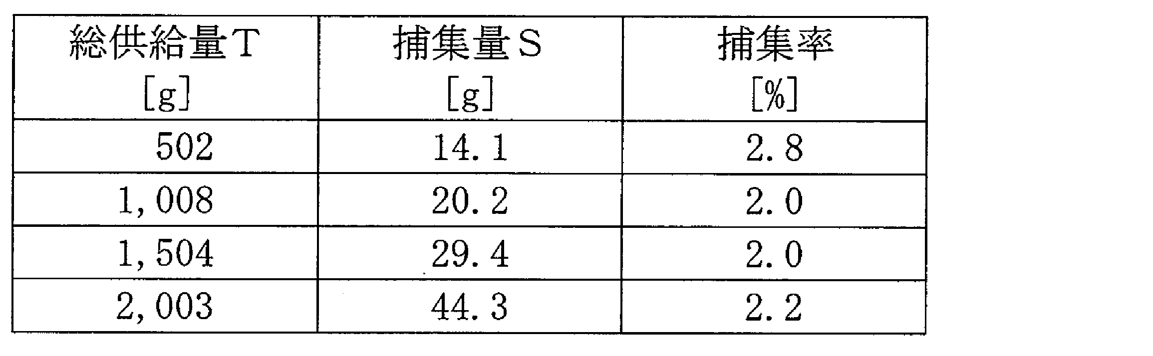
- the test conditions are as follows. ⁇ Abrasive: WAW1000 (Shinto Kogyo Co., Ltd.) ⁇ Supply amount: 100 g / min ⁇ Operating time: 10 minutes ⁇ Pulse air (pressure gas) injection interval: 10 seconds
- the collection rate is a ratio of the powder collected by the dust collector 4 and is derived from the following formula based on the total supply amount and the amount collected by the dust collector 4.
- Table 1 shows the collection rate when the supply amount of the powder was changed.
- polishing processing mechanism (stirring mechanism 20), 4 dust collector, 5 discharge mechanism, 10 cyclone type classification device, 11c storage section, 11d discharge port, 11e inclined surface, 42 dust collection filter, 43 ... Dust collection filter collecting member, 50: opening / closing member, 50e: sealing member, 51: restricting member, 52: injector, 52a: injection tube, AX: central axis (center of swirling airflow), G: abrasive, S: polishing Processing system, W: Workpiece.
Landscapes
- Chemical & Material Sciences (AREA)
- Chemical Kinetics & Catalysis (AREA)
- Engineering & Computer Science (AREA)
- Mechanical Engineering (AREA)
- Cyclones (AREA)
- Combined Means For Separation Of Solids (AREA)
- Feeding, Discharge, Calcimining, Fusing, And Gas-Generation Devices (AREA)
Abstract
Description
投入部10aは、後述する撹拌機構20からの研磨材G及び粉塵を含む粉体を受けてサイクロン本体11の内部に投入する。
・縮径部11b:上部内径186mm、下部内径100mm、高さ280mm
・排出口11d:上辺90mm、下辺80mm、高さ40mm
上記実施形態の排出機構5によれば、噴射器52から圧縮気体が噴射されたときに圧縮気体の圧力によって排出口11dが開放され、圧縮気体の噴射が停止されたときにホッパ12と貯留部11cとの圧力差により排出口11dが閉鎖される。これにより、ホッパ12からサイクロン本体11に研磨材Gが逆流することを防止することができるので、再使用可能な研磨材Gの高い分級精度を維持しながら、サイクロン式分級装置10から粉体を排出することができる。
以下、サイクロン式分級装置10の分級精度について実施例により確認した。
・研磨材 :WA♯1000(新東工業株式会社製)
・供給量 :100g/min
・稼働時間 :10分間
・パルスエア(圧力気体)の噴射間隔:10秒

Claims (9)
- 粉体の分級を行うサイクロン式分級装置に設けられ、前記サイクロン式分級装置の貯留部に貯留された粉体を排出する排出機構であって、
前記貯留部に形成された排出口を開閉するための開閉部材と、
前記貯留部に貯留された前記粉体に対してパルス状に圧縮気体を噴射する噴射器と、を備え、
前記開閉部材は、
前記噴射器から前記圧縮気体が噴射されたときに、前記圧縮気体による押圧力を受けて前記排出口を開放し、
前記噴射器から前記圧縮気体が噴射されていないときに、前記貯留部の負圧により前記貯留部側に付勢され前記排出口を閉鎖するように構成されている、
排出機構。 - 前記開閉部材が前記貯留部の負圧により前記排出口を閉鎖できるように、前記排出口に対する前記開閉部材の変位量を所定の範囲に制限する制限部材を更に備える、請求項1に記載の排出機構。
- 前記噴射器は、前記粉体に前記圧縮気体を噴射したときに、該粉体が飛散することがない位置に配設されている、請求項1又は請求項2に記載の排出機構。
- 前記サイクロン式分級装置は、その内部に旋回気流を生成する筒状のサイクロン本体を含み、前記貯留部は前記サイクロン本体の下部に設けられ、
前記噴射器は、前記サイクロン本体の中心軸線に沿って延び、その端部から前記圧縮気体を噴射する噴射管を有している、請求項1~3の何れか一項に記載の排出機構。 - 前記貯留部に取り付けられ、前記開閉部材が前記排出口を閉鎖したときに、前記開閉部材と当接して前記貯留部内の空間を封止する密閉部材を更に備える、請求項1~4の何れか一項に記載の排出機構。
- 請求項1~5の何れか一項に記載の排出機構を備えるサイクロン式分級装置。
- 前記排出口は、下方に向かうにつれて開口幅が狭くなるように前記貯留部の傾斜面に形成されている、請求項6に記載のサイクロン式分級装置。
- 請求項6又は7に記載のサイクロン式分級装置と、研磨材を用いて被加工物を研磨する研磨加工機構と、を備えた研磨加工システムであって、
前記サイクロン式分級装置は、前記被加工物の研磨に用いた前記研磨材を含む粉体から再使用可能な研磨材を分級する、研磨加工システム。 - 集塵機を更に備え、
前記集塵機は、集塵フィルタと、集塵フィルタ回収部材を備え、
前記集塵フィルタ回収部材は、両端に開口部を有する筒状に形成されており、
前記集塵フィルタが前記集塵機に取り付けられた状態では、前記集塵フィルタ回収部材は蛇腹状に折りたたまれて配置されており、
前記集塵フィルタを前記集塵機から取り外すときに、両端の開口部を閉止して前記集塵フィルタを包んだ状態で前記集塵フィルタを前記集塵機から取り外すことが可能に構成されている、請求項8に記載の研磨加工システム。
Priority Applications (3)
| Application Number | Priority Date | Filing Date | Title |
|---|---|---|---|
| JP2020527487A JP7215482B2 (ja) | 2018-06-29 | 2019-06-21 | サイクロン式分級装置の排出機構、サイクロン式分級装置及び研磨加工システム |
| CN201980016037.4A CN111788005B (zh) | 2018-06-29 | 2019-06-21 | 旋风分离式分级装置的排出机构、旋风分离式分级装置以及研磨加工系统 |
| KR1020207024387A KR102646611B1 (ko) | 2018-06-29 | 2019-06-21 | 사이클론식 분급 장치의 배출 기구, 사이클론식 분급 장치 및 연마 가공 시스템 |
Applications Claiming Priority (2)
| Application Number | Priority Date | Filing Date | Title |
|---|---|---|---|
| JP2018-124384 | 2018-06-29 | ||
| JP2018124384 | 2018-06-29 |
Publications (1)
| Publication Number | Publication Date |
|---|---|
| WO2020004280A1 true WO2020004280A1 (ja) | 2020-01-02 |
Family
ID=68986905
Family Applications (1)
| Application Number | Title | Priority Date | Filing Date |
|---|---|---|---|
| PCT/JP2019/024784 Ceased WO2020004280A1 (ja) | 2018-06-29 | 2019-06-21 | サイクロン式分級装置の排出機構、サイクロン式分級装置及び研磨加工システム |
Country Status (5)
| Country | Link |
|---|---|
| JP (1) | JP7215482B2 (ja) |
| KR (1) | KR102646611B1 (ja) |
| CN (1) | CN111788005B (ja) |
| TW (1) | TWI802716B (ja) |
| WO (1) | WO2020004280A1 (ja) |
Cited By (2)
| Publication number | Priority date | Publication date | Assignee | Title |
|---|---|---|---|---|
| JP2022130957A (ja) * | 2021-02-26 | 2022-09-07 | 新東工業株式会社 | 集塵装置及び集塵方法 |
| JP7456372B2 (ja) | 2020-12-24 | 2024-03-27 | 新東工業株式会社 | 砂供給装置 |
Families Citing this family (5)
| Publication number | Priority date | Publication date | Assignee | Title |
|---|---|---|---|---|
| RU210012U1 (ru) * | 2021-10-13 | 2022-03-24 | Федеральное государственное бюджетное образовательное учреждение высшего образования "Волгоградский государственный технический университет" (ВолгГТУ) | Циклон |
| KR102778809B1 (ko) | 2021-11-02 | 2025-03-07 | 주식회사 엘지화학 | 유동층을 이용한 분급 시스템 |
| CN116510436B (zh) * | 2023-07-03 | 2023-09-08 | 江苏英达机械有限公司 | 一种抛丸机用斜插式滤筒除尘器 |
| KR102632521B1 (ko) * | 2023-10-05 | 2024-02-02 | 조인형 | 활성탄 흡입 및 집진 장치 |
| KR20240017869A (ko) * | 2023-10-05 | 2024-02-08 | 조인형 | 활성탄 흡입 및 집진 장치 |
Citations (4)
| Publication number | Priority date | Publication date | Assignee | Title |
|---|---|---|---|---|
| JPS58166850U (ja) * | 1982-04-30 | 1983-11-07 | 株式会社細川粉体工学研究所 | 粉粒体の排出装置 |
| JP3027439U (ja) * | 1996-01-31 | 1996-08-09 | レオン自動機株式会社 | 粉体排出装置 |
| JP2009189965A (ja) * | 2008-02-15 | 2009-08-27 | Sumitomo Metal Mining Co Ltd | サイクロン集塵機の粉塵排出装置 |
| JP5429301B2 (ja) * | 2010-11-19 | 2014-02-26 | 新東工業株式会社 | サイクロン式分級装置 |
Family Cites Families (14)
| Publication number | Priority date | Publication date | Assignee | Title |
|---|---|---|---|---|
| JPS5183032A (ja) * | 1975-11-29 | 1976-07-21 | Kobe Steel Ltd | Choteionkoyoyosetsubo |
| US5160222A (en) * | 1990-11-30 | 1992-11-03 | Tech-Air, Inc. | Pneumatic conveying system |
| DE4240048C2 (de) * | 1992-11-28 | 2002-11-07 | Mahle Filtersysteme Gmbh | Staubaustragventil |
| KR19990013114U (ko) * | 1997-09-20 | 1999-04-15 | 장형수 | 원심 펌프용 푸트밸브의 밀폐구조 |
| JP4560305B2 (ja) * | 2004-02-24 | 2010-10-13 | 株式会社松井製作所 | 吸引式粉粒体捕集器、気流混合吸引式粉粒体捕集器 |
| JP2006015213A (ja) * | 2004-06-30 | 2006-01-19 | Daikin Ind Ltd | フィルタ交換装置及びフィルタ交換方法 |
| KR200402399Y1 (ko) * | 2005-08-29 | 2005-12-02 | 대한전기공업 주식회사 | 호퍼로다의 댐퍼브라켓 |
| JP2009000762A (ja) | 2007-06-20 | 2009-01-08 | Shin Meiwa Ind Co Ltd | ブラスト加工装置 |
| JP4725894B2 (ja) * | 2007-07-04 | 2011-07-13 | 新明コンベヤ株式会社 | 吸引ダクトに於ける粉塵除去装置及び粉塵除去方法 |
| JP5736618B2 (ja) * | 2011-11-22 | 2015-06-17 | 日本スピンドル製造株式会社 | 集塵装置 |
| CN202398440U (zh) * | 2012-01-10 | 2012-08-29 | 河南黎明重工科技股份有限公司 | 一种旋风式除尘器 |
| US20130209181A1 (en) * | 2012-02-15 | 2013-08-15 | Gregory A. Van Arsdale | Self-emptying vacuum apparatus for use by gold prospectors |
| JP2015042572A (ja) * | 2013-08-26 | 2015-03-05 | 株式会社松井製作所 | 粉粒体材料の捕集装置 |
| CN203620810U (zh) * | 2013-12-09 | 2014-06-04 | 成都科盛石油科技有限公司 | 一种基于对粉末进行多次筛选的设备 |
-
2019
- 2019-06-21 CN CN201980016037.4A patent/CN111788005B/zh active Active
- 2019-06-21 KR KR1020207024387A patent/KR102646611B1/ko active Active
- 2019-06-21 JP JP2020527487A patent/JP7215482B2/ja active Active
- 2019-06-21 WO PCT/JP2019/024784 patent/WO2020004280A1/ja not_active Ceased
- 2019-06-28 TW TW108122751A patent/TWI802716B/zh active
Patent Citations (4)
| Publication number | Priority date | Publication date | Assignee | Title |
|---|---|---|---|---|
| JPS58166850U (ja) * | 1982-04-30 | 1983-11-07 | 株式会社細川粉体工学研究所 | 粉粒体の排出装置 |
| JP3027439U (ja) * | 1996-01-31 | 1996-08-09 | レオン自動機株式会社 | 粉体排出装置 |
| JP2009189965A (ja) * | 2008-02-15 | 2009-08-27 | Sumitomo Metal Mining Co Ltd | サイクロン集塵機の粉塵排出装置 |
| JP5429301B2 (ja) * | 2010-11-19 | 2014-02-26 | 新東工業株式会社 | サイクロン式分級装置 |
Cited By (3)
| Publication number | Priority date | Publication date | Assignee | Title |
|---|---|---|---|---|
| JP7456372B2 (ja) | 2020-12-24 | 2024-03-27 | 新東工業株式会社 | 砂供給装置 |
| JP2022130957A (ja) * | 2021-02-26 | 2022-09-07 | 新東工業株式会社 | 集塵装置及び集塵方法 |
| JP7635577B2 (ja) | 2021-02-26 | 2025-02-26 | 新東工業株式会社 | 集塵装置及び集塵方法 |
Also Published As
| Publication number | Publication date |
|---|---|
| TWI802716B (zh) | 2023-05-21 |
| KR20210023797A (ko) | 2021-03-04 |
| TW202005717A (zh) | 2020-02-01 |
| JP7215482B2 (ja) | 2023-01-31 |
| JPWO2020004280A1 (ja) | 2021-08-02 |
| CN111788005A (zh) | 2020-10-16 |
| KR102646611B1 (ko) | 2024-03-13 |
| CN111788005B (zh) | 2022-12-27 |
Similar Documents
| Publication | Publication Date | Title |
|---|---|---|
| JP7215482B2 (ja) | サイクロン式分級装置の排出機構、サイクロン式分級装置及び研磨加工システム | |
| JP6489132B2 (ja) | 研磨装置および研磨方法 | |
| US7730896B2 (en) | Dry cleaning device and dry cleaning method | |
| JP2016067991A (ja) | 洗浄媒体吸引ユニット及び乾式洗浄装置 | |
| CN106457519A (zh) | 喷丸加工装置以及喷丸加工装置列 | |
| CN102725107B (zh) | 喷丸加工装置 | |
| TWI532532B (zh) | Tornado classification device | |
| JP6627952B2 (ja) | 分級機構 | |
| CN204748347U (zh) | 抛丸装置 | |
| US9370796B2 (en) | Particle separator | |
| JP4315905B2 (ja) | 粒体の粉取り兼垂直搬送兼集塵の方法及び装置 | |
| JP6196516B2 (ja) | ショットブラスト装置 | |
| US20040126141A1 (en) | Detoning apparatus and method | |
| JP7304006B2 (ja) | 研磨加工装置、研磨加工システム及び研磨加工方法 | |
| JP7146172B2 (ja) | 異物除去装置及び異物除去装置を備えたブラスト加工装置 | |
| JP2020199208A (ja) | 固形物の粉取り装置 | |
| KR100341365B1 (ko) | 미분쇄기의분진발생차단구조 | |
| JP7053175B2 (ja) | 集塵システム | |
| JP2828762B2 (ja) | 放射性廃棄物の除染装置 | |
| JP3175192B2 (ja) | 吸引ノズル | |
| JP2025031220A (ja) | 粉体供給ノズル、気流式粉砕機および粉体供給方法 | |
| JP2004017258A (ja) | 皮膜研創除去方法 | |
| JP2023041387A (ja) | ブラスト機 | |
| KR20100110095A (ko) | 콘크리트 구조물의 면 보수를 위한 건식 에어 브라스트 장치 | |
| JP2002331458A (ja) | サンドブラスト加工における研磨材供給方法および装置 |
Legal Events
| Date | Code | Title | Description |
|---|---|---|---|
| 121 | Ep: the epo has been informed by wipo that ep was designated in this application |
Ref document number: 19826271 Country of ref document: EP Kind code of ref document: A1 |
|
| ENP | Entry into the national phase |
Ref document number: 2020527487 Country of ref document: JP Kind code of ref document: A |
|
| ENP | Entry into the national phase |
Ref document number: 20207024387 Country of ref document: KR Kind code of ref document: A |
|
| NENP | Non-entry into the national phase |
Ref country code: DE |
|
| 122 | Ep: pct application non-entry in european phase |
Ref document number: 19826271 Country of ref document: EP Kind code of ref document: A1 |