WO2020004044A1 - Ponceuse à courroie - Google Patents
Ponceuse à courroie Download PDFInfo
- Publication number
- WO2020004044A1 WO2020004044A1 PCT/JP2019/023350 JP2019023350W WO2020004044A1 WO 2020004044 A1 WO2020004044 A1 WO 2020004044A1 JP 2019023350 W JP2019023350 W JP 2019023350W WO 2020004044 A1 WO2020004044 A1 WO 2020004044A1
- Authority
- WO
- WIPO (PCT)
- Prior art keywords
- lock
- operation unit
- unit
- switch
- lever
- Prior art date
Links
Images


Classifications
-
- B—PERFORMING OPERATIONS; TRANSPORTING
- B24—GRINDING; POLISHING
- B24B—MACHINES, DEVICES, OR PROCESSES FOR GRINDING OR POLISHING; DRESSING OR CONDITIONING OF ABRADING SURFACES; FEEDING OF GRINDING, POLISHING, OR LAPPING AGENTS
- B24B23/00—Portable grinding machines, e.g. hand-guided; Accessories therefor
- B24B23/06—Portable grinding machines, e.g. hand-guided; Accessories therefor with abrasive belts, e.g. with endless travelling belts; Accessories therefor
-
- B—PERFORMING OPERATIONS; TRANSPORTING
- B25—HAND TOOLS; PORTABLE POWER-DRIVEN TOOLS; MANIPULATORS
- B25F—COMBINATION OR MULTI-PURPOSE TOOLS NOT OTHERWISE PROVIDED FOR; DETAILS OR COMPONENTS OF PORTABLE POWER-DRIVEN TOOLS NOT PARTICULARLY RELATED TO THE OPERATIONS PERFORMED AND NOT OTHERWISE PROVIDED FOR
- B25F5/00—Details or components of portable power-driven tools not particularly related to the operations performed and not otherwise provided for
- B25F5/02—Construction of casings, bodies or handles
Definitions
- the present invention relates to a belt sander having an endless sanding belt at a lower portion of a housing.
- Patent Document 1 Japanese Patent Application Laid-Open No. 2014-148018
- a belt sander in which a trigger-like switch operation unit for instructing start and stop of a motor for driving a sanding belt is provided at a lower portion of a handle.
- a lock-on mechanism is provided for continuing the motor start command without continuing to operate the switch operation unit, in order to use the belt sander with the sanding belt turned upside down and stopped on a flat surface.
- a main object of the present invention is to provide a belt sander in which an operation relating to a lock-on mechanism can be easily performed.
- Another main object of the present invention is to provide a belt sander in which unintended movement during lock-on mechanism operation is prevented.
- the invention according to claim 1 is configured such that a gripper that can be gripped by an operator, an electric motor for driving a sanding belt, and an ON operation related to the electric motor are possible. And a first operation unit capable of maintaining the on operation, and a second operation unit capable of performing the on operation of the electric motor, wherein the electric motor includes the first operation unit and The second operation unit is rotated by an ON operation of both of the second operation units, and the second operation unit is arranged at a position operable by a hand holding the grip unit.
- the off operation of the second operation section is performed by releasing a hand from the grip section.
- the second operation section is disposed on a surface of the grip section on the worker side, and the on operation of the second operation section is a push operation;
- the off operation of the second operation unit is a release of the push operation.
- the second operation unit is pressed against the flat surface in a state where the second operation unit is turned upside down in contact with the flat surface.
- the second operating portion is shaped like a dorsal fin.
- the first operation portion is disposed on a surface of the grip portion opposite to a surface on the worker side, and an ON operation of the first operation portion is performed by:
- the pull operation is performed, and the ON operation of the first operation unit is maintained by a lock operation unit capable of switching between maintaining and canceling the state of the pull operation, and the OFF operation of the first operation unit is controlled by the pull operation. It is characterized by cancellation.
- a spring biasing the spring is interposed.
- the spring is a torsion spring.
- the main effect of the present invention is to provide a belt sander in which an operation relating to a lock-on mechanism can be easily performed.
- Another main advantage of the present invention is to provide a belt sander that prevents unintentional movement during operation of the lock-on mechanism.
- FIG. 2 is a top view of FIG. 1.
- FIG. 2 is a right side view of the lid opening of FIG. 1.
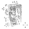
- (A) is an enlarged view of the central part of FIG. 3 when the switch lever is pushed in
- (b) is a view similar to (a) when the switch lever and the lock-off lever are pushed.
- FIG. 4A is a central longitudinal sectional view of the central portion of FIG. 3, and
- FIG. 4B is a sectional view taken along line II of FIG. 5A is a view similar to FIG. 5A when the switch lever and the lock-off lever are pushed in, and
- FIG. 5B is a cross-sectional view taken along the line II-II of FIG.
- FIG. 6 is a view similar to FIG. 5A when the lock-off lever is further pushed in.
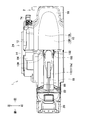
- FIG. 1 is a perspective view of a belt sander 1 according to the embodiment.
- FIG. 2 is a top view of the belt sander 1 (the right of the figure is in front of the belt sander 1 and the upper side of the figure is the left of the belt sander 1).
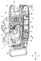
- FIG. 3 is a right side view of the opening of the belt sander 1 (the right side of the figure is in front of the belt sander 1 and the upper side is above the belt sander 1).
- the belt sander 1 includes a housing 2, a brushless motor 3, a power transmission unit (not shown) for transmitting the power, and a belt driving unit 6 for driving the sanding belt B.
- the housing 2 has a main body housing 10, a horizontal housing 12, and a side cover 14.
- the main body housing 10 holds the brushless motor 3, which is an electric motor, in the upper center, and holds the belt drive unit 6 in a lower part with a part of the lower end exposed.
- An upper rear portion of the main body housing 10 and a portion located behind the brushless motor 3 is an outer shell of a grip 16 (grip portion) extending in the front-rear direction while being spaced from the belt drive unit 6.
- An upper front portion of the main body housing 10 and a portion located in front of the brushless motor 3 is an outer contour of a front grip 18 extending in the front-rear direction while being spaced from the belt driving unit 6.
- the front half (rear half) of the grip 16 and the front grip 18 are each large enough to be wrapped with one hand.
- the rear end of the body housing 10 extends vertically so as to connect the outer shell of the rear end of the grip 16 and the outer shell of the rear end of the belt drive unit 6.
- a battery mounting portion 22 that can be mounted from above with a terminal portion (not shown) of the battery pack 20 serving as a power source facing forward is formed.
- the main body housing 10 is formed by screwing a left main body housing 10L and a right main body housing 10R that are half each other.
- the horizontal housing 12 holds a power transmission unit.
- the side cover 14 covers the power transmission unit.
- the horizontal housing 12 and the side cover 14 are screwed to the left side surface of the left main housing 10L.
- the main body housing 10 and members such as the brushless motor 3, the power transmission unit, and the belt driving unit 6 held by the main body housing 10, the lateral housing 12, the side cover 14, and the members held by the main body 24 form the main body 24 of the belt sander 1.
- the upper end of the battery pack 20 mounted on the battery mounting portion 22 does not protrude above the upper end surface of the main body 24.
- the brushless motor 3 has a cylindrical stator 30 and a rotor 32 penetrating the stator 30 (inner rotor type).
- the motor shaft 34 arranged at the axis of the rotor 32 faces in the left-right direction.
- a controller 36 that controls the rotation state and the like of the brushless motor 3 is held in the main body housing 10 and in front of the lower portion of the brushless motor 3.
- the controller 36 is electrically connected to the brushless motor 3 and the battery mounting unit 22.
- the controller 36 has a control circuit board (not shown) having a square shape in a top view.
- the control circuit board is electrically connected to a sensor circuit board (not shown) having a sensor for detecting the rotational position of the rotor 32.
- the control circuit board includes a control circuit including a microcomputer that transmits a control signal based on rotation position information of the rotor 32 detected by the sensor circuit board, and a brushless motor 3 based on a control signal received from the control circuit. And an auto-stop circuit that cuts off power supply to the brushless motor 3 so as not to be in an overdischarge or overcurrent state according to the detection result of the state of the battery pack 20. ing.
- a first switch 40 is held in the main body housing 10 and behind the brushless motor 3.
- the first switch 40 is turned off when the cylindrical plunger 44 projecting upward and downward from the upper portion of the first switch main body 42 moves upward and the length of the exposed portion of the plunger 44 exceeds a predetermined threshold.
- the plunger 44 moves downward, and switches on when the length of the exposed portion of the plunger 44 becomes equal to or less than a predetermined threshold.
- the first switch 40 is electrically connected to the controller 36.
- a second switch 50 is held in the main body housing 10 and in a rear portion of the grip 16.
- the actuator 54 that projects forward and backward from the lower front part of the second switch body 52 to the front as a fulcrum is moved backward, and the angle of the actuator 54 with respect to the front surface of the second switch body 52 is predetermined.
- the actuator 54 is turned off, the actuator 54 moves forward, and when the angle of the actuator 54 with respect to the front surface of the second switch body 52 becomes equal to or greater than a predetermined threshold value, the actuator 54 is turned on.
- the second switch 50 is electrically connected to the controller 36. When both the first switch 40 and the second switch 50 are turned on, the controller 36 supplies the power of the battery pack 20 obtained via the battery mounting section 22 to the brushless motor 3 to operate the brushless motor 3.
- the controller 36 does not supply power to the brushless motor 3 and does not operate the brushless motor 3 (switching the brushless motor 3 off).
- the front grip 18 is provided with a rotation speed adjustment dial 56 whose right end is exposed to the right side.
- the rotation speed adjustment dial 56 is electrically connected to the controller 36.
- the controller 36 sets the rotation speed of the brushless motor 3 according to the attitude (rotation position) of the rotation speed adjustment dial 56. Note that the rotation speed adjustment dial 56 may be omitted.
- the power transmission unit held by the horizontal housing 12 transmits the rotational force of the motor shaft 36 to the driving roller 60 of the belt driving unit 6.
- the power transmission unit is hung on a pulley integral with the left end of the motor shaft 36 protruding into the horizontal housing 12 and an intermediate shaft with a pulley connected to the drive roller 60 via a gear (reduction mechanism).
- An endless synchro belt is the main element.
- the belt driving unit 6 includes a cylindrical driving roller 60 disposed at a rear portion extending left and right, a cylindrical driven roller 62 disposed at a front portion in parallel with the driving roller 60, and each of these around an axis. And a support frame 64 rotatably supported.
- the driving roller 60 rotates in the direction of arrow C in FIG. 3 by the rotational force from the power transmission unit.
- a sanding belt B is stretched between the driving roller 60 and the driven roller 62.
- a plate 66 for pressing the sanding belt B toward the material to be polished is provided on the lower surface of the support frame 64.
- a rod-shaped front roller shaft 70 is passed through the driven roller 62 with a common central axis.
- the front roller shaft 70 is supported between the support portions 72a of a shaft frame 72 having a “U” -shaped support portion 72a in a top view at the front.
- the rear portion of the shaft frame 72 is an arm portion 72b that projects rearward from the rear right end of the support portion 72a.
- the arm part 72b is supported by the support frame 64 so as to be able to move back and forth.
- the rear end of the arm 72b is an operation lever 72c exposed from the right side of the support frame 64.
- the driven roller 62 When the support portion 72a is in the front and rear free state, the driven roller 62 is in the front and rear free state, and the sanding belt B can be attached and detached. On the other hand, if the state in which the support portion 72a is urged to the forward position while the sanding belt B is mounted is switched, the driven roller 62 is urged to the forward position, and the sanding belt B is stretched. On the left side surface of the main body housing 10, an adjustment knob 74 for restricting lateral displacement of the sanding belt B in the left-right direction is provided.
- a dust collection port 80 extending in the left-right direction is opened below the drive roller 60.
- a guide path communicating with the dust collection port 80, wrapping upward from behind the drive roller 60, further going leftward, and leading to a start end of a dust collection path (not shown except for the end) of the horizontal housing 12. 82 are formed.
- the end of the dust collection path is a discharge cylinder 84 formed to protrude rearward at the upper rear portion of the horizontal housing 12.
- a wireless communication adapter insertion portion 86 is formed on the right side surface of the main body housing 10 behind the dust collection port 80 and in front of the battery mounting portion 22.
- the wireless communication adapter insertion portion 86 is formed so as to be recessed leftward in a box shape with respect to the other right side portion of the main body housing 10, and the wireless communication adapter 88 can be inserted therein.
- the wireless communication adapter 88 is electrically connected to a wireless communication controller (not shown) mounted on the controller 36.
- the wireless communication adapter 88 performs wireless communication with a dust collector (not shown) as auxiliary equipment.
- the start and stop operations of the dust collector are linked with the start and stop operations of the belt sander 1 by wireless communication.
- the hose of the dust collector is connected to the discharge tube 84.
- association (pairing) for enabling wireless communication is performed between the wireless communication adapter 88 and the dust collector-side wireless communication adapter attached to the dust collector. Pairing is performed by an operator pressing a button of the dust collector-side wireless communication adapter and operating a button of the wireless communication adapter 88 within a predetermined time.
- start information indicating the start is transmitted from the wireless communication adapter 88 to the dust collector, and the start information of the start information is transmitted by the dust collector-side wireless communication adapter.
- the dust collector starts automatically based on the reception.
- the wireless communication state is notified to the worker by the lighting state of the lamp provided on the wireless communication adapter 88.
- a seesaw-like switch lever 90 is provided above the plunger 44 of the first switch 40.
- the switch lever 90 is arranged on the lower surface of the grip 16, that is, on the surface of the grip 16 opposite to the surface on the worker side.
- the switch lever 90 has a boss portion 90a formed in a cylindrical shape extending in the left-right direction at a central portion, a trigger portion 90b formed in a trigger shape behind the boss portion 90a, and a right-left side at a front side of the boss portion 90a. It has a pair of ribs 90c formed so as to protrude upward, and an action portion 90d formed on the front side of the rib 90c and in contact with the upper end of the plunger 44.
- a convex portion 92 protruding in the left-right direction from the inner surface of the main body housing 10 is inserted.
- the switch lever 90 can swing around the protrusion 92.
- the trigger portion 90b can be exposed from an opening formed in a front lower portion of the grip 16 and extending in the front-rear direction.
- the switch lever 90 is moved from a maximum protruding position in which a locking portion 90e formed so as to protrude rearward in a rear upper portion of the trigger portion 90b is hooked on an edge of the opening (P1 in FIG. 4A, FIG.
- a torsion spring 108 which is an elastic body (spring), is provided outside the boss 90a.
- the torsion spring 108 has a coil-shaped coil portion 108a mainly exhibiting elasticity and an arm portion 108b extending rearward from the coil portion 108a, and the coil portion 108a is provided outside the boss 90a of the switch lever 90. Be placed.
- the torsion spring 108 urges the switch lever 90 to the maximum projecting posture side. Note that the plunger 44 of the first switch 40 is urged upward, and the plunger 44 also urges the switch lever 90 to the maximum projecting posture side. Such biasing of the plunger 44 may be omitted.
- a lock-on portion 100 is provided above the pair of ribs 90c.
- the lock-on section 100 has a lock-on button 102 extending in the left-right direction, and a compression spring 104 that is an elastic body.
- a lock-on button 102 serving as a lock operation unit includes a cylindrical lock-on button main body 102a, a protruding part 102b having a bottomed hole that protrudes rearward from the lock-on button main body 102a and opens to the top, and a lock-on button.
- a pair of left and right recesses 102c is provided in the center of the main body 102a so as to be recessed upward from the lower end in a slit shape with a bottom.
- the lower rear surface of the lock-on button main body 102a and the lower surface of the protrusion 102b are in contact with the front protrusion 94.
- a compression spring 104 is disposed in the bottomed hole of the protruding portion 102b so as to extend in the left-right direction.
- An upper rib 106 protruding downward from the inner surface of the main body housing 10 extends so as to reach the opening of the bottomed hole, and prevents the compression spring 104 from coming off.
- the lock-on button 102 is supported by the main body housing 10 (outline of the grip 16) so as to be movable in the left-right direction while passing through lock-on button holes 109 provided on the right and left sides of the outer edge of the front end of the grip 16 respectively.
- the compression spring 104 biases the lock-on button 102 to be located at the center, that is, biases the lock-on button 102 to a position where the center in the left-right direction matches the center of the grip 16 in the
- the rib 90c of the switch lever 90 enters the recess 102c of the lock-on button 102. Therefore, when the switch lever 90 swings, the movement of the rib 90c is not hindered by the lock-on button 102, and the switch lever 90 can be retracted. When the switch lever 90 is pulled in by a predetermined amount or more, the rib 90c comes off from the concave portion 102c. At this time, the first switch 40 is on.
- the operation when the lock-on button 102 is moved to the left is the same as the operation when the lock-on button 102 is moved to the right.
- the maintenance of the retracted operation state of the switch lever 90 is released when the lock-on button 102 is returned to the center and the rib 90c can pass through the recess 102c.
- the switch lever 90 and the lock-on unit 100 are components of a first operation unit capable of turning on the brushless motor 3 (pulling in the switch lever 90) and maintaining the lock-on state. is there.
- the compression spring 104 may be omitted.
- a lock-off portion 110 is provided behind the lock-on button 102 and at the center of the grip 16.
- the lock-off section 110 includes a lock-off lever 112 extending in the front-rear direction.
- the lock-off lever 112 is arranged at a position where the lock-off lever 112 can be operated by a hand holding the grip 16.
- the lock-off lever 112 has a dorsal fin-shaped lock-off lever main body 112a whose upper part is exposed, a shaft hole 112b provided at the front end of the lock-off lever main body 112a so as to extend in the left-right direction, and a shaft hole.
- a projecting amount regulating portion 112c provided to extend vertically below the portion 112b; a torsion spring holding portion 112d provided at a rear lower portion of a rear portion of the lock-off lever main body portion 112a which projects downward from a front portion; Having.
- a projection 116 projecting from the inner surface of the main body housing 10 in the left-right direction is inserted into the shaft hole 112b.
- the lock-off lever 112 can swing around the convex portion 116.
- the lock-off lever main body 112a can be exposed from an opening extending in the front-rear direction formed at the center of the upper surface of the grip 16 on the worker side.
- the lock-off lever 112 is horizontally positioned such that the upper surface of the lock-off lever main body 112a is horizontal from the maximum protruding position in which the protrusion amount regulating portion 112c hits the rear protrusion 96 (see O1 in FIG. 4B and FIG. 5A).
- the lock-off lever main body 112a reaches the buried attitude in which the lower rear surface of the lock-off lever main body 112a contacts the regulating protrusion 118 projecting upward from the inner surface of the main body housing 10 (FIG. (B), see FIG. 7), and can swing.
- the torsion spring holding portion 112d projecting rearward is hooked on the rear edge of the opening at the center of the outer periphery of the grip 16.
- the rear end of the arm portion 108b of the torsion spring 108 is held by the torsion spring holding portion 112d.
- the torsion spring 108 is interposed between the switch lever 90 and the lock-off lever 112, and urges the lock-off lever 112 in addition to the switch lever 90 to the maximum projecting posture side.
- the lock-off lever 112 in the maximum projecting posture moves the actuator 54 of the second switch 50 backward in the torsion spring holding portion 112d projecting backward, and turns off the second switch 50.
- the lock-off lever 112 is pushed in from the maximum protruding posture, and is separated from the actuator 54 by being pushed in a predetermined amount before the horizontal posture, whereby the actuator 54 moves forward and the second switch 50 is turned on. It becomes.
- the actuator 54 is biased forward. Therefore, both the lock-off lever 112 in the horizontal posture (FIG. 6) and the lock-off lever 112 in the buried posture (FIG. 7) turn on the second switch 50.
- the lock-off lever 112 has a shape that avoids the switch lever 90 that is in the buried posture even if it is in the buried posture (a protruding shape of the rear portion below the front portion) (see FIG. 7).
- the lock-off unit 110 (and the second switch 50) is a component of a second operation unit capable of turning on the brushless motor 3 (pressing the lock-off lever 112).
- Such a belt sander 1 operates, for example, as follows. That is, when the charged battery pack 20 is mounted on the battery mounting portion 22 and the lock-on button 102 is located at the center, the operator pulls the switch lever 90 when grasping the grip 16 (the first operation portion is turned on). When the lock-off lever 112 is pressed together with the operation (on operation of the second operation unit), both the first switch 40 and the second switch 50 are turned on, and the controller 36 supplies the power of the battery pack 20 to the brushless motor 3. Then, the motor shaft 34 is driven to rotate. The rotation of the motor shaft 34 is transmitted to the belt driving unit 6 via the power transmission unit, and the sanding belt B is driven by the belt driving unit 6.
- the sanding belt B thus rotated is pressed against the workpiece by the grip of the grip 16 (further the front grip 18) on the upper part of the main body housing 10 and moved so as to be polished. Work such as polishing is performed on the surface of the material.
- the first switch 40 At least one of the second switches 50 is turned off, the power supply to the brushless motor 3 of the battery pack 20 is stopped by the controller 36, the rotation of the motor shaft 34 is stopped, and the driving of the sanding belt B is stopped.
- the lock-on unit 100 (first switch 40) and the lock-off unit 110 (second switch 50) are double switches related to the brushless motor 3.
- the torsion spring 108 returns to a projecting position of a predetermined projecting amount or more by the urging force. Then, the second switch 50 is turned off, and the sanding belt B stops. Therefore, in a case where the lock-on unit 100 is provided but the lock-off unit 110 is not provided, the worker releases the grip 16 in a state where the rotation of the sanding belt B is continued during the lock-on state, and the belt sander in that case is not intended. The belt sander 1 having the lock-off portion 110 is prevented from moving away from the belt.
- the belt sander 1 can be easily used on a flat surface in a state where the sanding belt B is turned upside down (FIG. 6). That is, the uppermost surface of the main body portion 24 is the central portion of the main body housing 10, and the extended surface thereof is schematically shown by a dashed line G in FIGS. 5A to 7. 6 comes in contact with the flat surface, and a part of the flat surface coincides with the dashed line G in FIG. At this time, the lock-off lever 112 is pushed on the flat surface (the ON operation of the second operation unit), naturally assumes a horizontal posture, and the second switch 50 is turned on.
- the operator can operate the sanding belt B to be driven without first operating the lock-on button 102 and the lock-off lever 112 only by operating the lock-on unit 100 first.
- the upside down state since the sanding belt B is not placed on the material to be polished or the like, unintended movement by the sanding belt B is not performed.
- the lock-off lever 112 returns to the maximum protruding posture side by separating from the flat surface (the second operation section). Off operation), the driving of the sanding belt B via the second switch 50, the controller 36 and the brushless motor 3 is stopped. Therefore, even if the lock-on unit 100 remains operating, the lock-off unit 110 operates to prevent unintended movement of the belt sander 1.
- the wireless communication adapter 88 is controlled by the wireless communication controller mounted on the controller 36, and the dust collector is activated by wireless communication with the dust collector-side wireless communication adapter. Is made. Dust collection by suction of air from the dust collector is performed as follows. That is, the dust generated around the sanding belt B that is appropriately rotated by the processing passes through the dust collection port 80, the guide path 82, and the dust collection path, and is sucked by the dust collector connected to the discharge cylinder 84. On the other hand, when one of the first switch 40 and the second switch 50 is turned off, the operation of the dust collector is stopped via the wireless communication adapter 88 controlled by the wireless communication controller.
- the brushless motor 3 includes a switch lever 90 and a lock-on unit 100 that can be turned on, and a lock-off unit 110 that can be turned on according to the brushless motor 3.
- the lock-off unit 110 is arranged at a position where the lock-off unit 110 can be operated by a hand holding the grip 16. Therefore, the operator operates the brushless motor 3 and, consequently, the sanding belt B with the lock-off portion 110 which can be operated by the hand holding the grip 16 even if the switch lever 90 is kept on by the lock-on portion 100. be able to. Therefore, the belt sander 1 in which the operation regarding the lock-on unit 100 can be easily performed is provided.
- the turning-off operation of the lock-off unit 110 is performed by releasing the hand from the grip 16. Therefore, it is possible to prevent the belt sander 1 from moving unintentionally when the hand is released from the grip 16 in the lock-on state.
- the lock-off unit 110 is disposed on the upper surface of the grip 16 on the worker side, and the ON operation of the lock-off unit 110 is a push operation, and the OFF operation of the lock-off unit 110 is a push operation. It is cancellation of. Therefore, the operator can switch the driving of the brushless motor 3 and thus the sanding belt B depending on whether the lock-off lever 112 is pushed or released, and the operation is further facilitated.
- the switch lever 90 is disposed on the lower surface of the grip 16 opposite to the surface on the worker side.
- the ON operation of the switch lever 90 is a pull operation, and the ON operation of the switch lever 90 is performed.
- the maintenance is performed by the lock-on button 102 capable of switching between maintaining and releasing the state of the pull operation, and the OFF operation of the switch lever 90 is the release of the pull operation. Accordingly, the operator can switch between locking and unlocking the switch lever 90, and can switch the state of the switch lever 90 in accordance with the work content.
- a torsion spring 108 that urges both the switch lever 90 and the lock-off lever 112 in a direction of an OFF operation state is interposed. Therefore, the urging force necessary for the switch lever 90 and the lock-off lever 112 to return to the maximum projecting posture side is applied by the common torsion spring 108.
- the first operation unit may be a button switch, a toggle switch, or the like instead of the switch lever 90 and the lock-on unit 100 (a lock-on mechanism including a lock-on button 102 that can be locked to the switch lever 90).
- the switch lever 90 a toggle switch
- the lock-on unit 100 a lock-on mechanism including a lock-on button 102 that can be locked to the switch lever 90.
- the toggle switch may be switched so that the on-operation is maintained by tilting the operation lever to one side, and the off-operation is maintained by tilting the operation lever to the other side.
- the second operation unit (lock-off unit 110) includes a lock-off mechanism such as an arm that returns the lock-on button 102 to the center instead of the lock-off lever 112 that switches the second switch 50, which is one of the dual switches. May be.
- the second operation unit may be a button switch, a toggle switch, or the like, similarly to the first operation unit.
- the lock-off portion 110 may be provided on the front grip 18 or between the grip 16 and the front grip 18.
- the switch lever 90 and the lock-off lever 112 may be urged toward the maximum projecting posture by an elastic body (spring) other than the torsion spring. Further, the switch lever 90 and the lock-off lever 112 may be urged toward the maximum protruding posture by separate elastic bodies.
- the synchro belt and the pulley are replaced by gears, the battery pack 20 can be charged in the belt sander 1 on which the battery pack 20 is mounted, a single-use battery pack is used, or a power cord is used instead of the battery mounting unit 22.
- the main body housing 10 is not divided into right and left halves but is integrated, the main body housing 10 is further divided, or a part of the main body housing 10 and the horizontal housing 12 are integrated. For example, the function, arrangement, type, number, material, and presence / absence of the various members may be appropriately changed.
Landscapes
- Engineering & Computer Science (AREA)
- Mechanical Engineering (AREA)
- Finish Polishing, Edge Sharpening, And Grinding By Specific Grinding Devices (AREA)
- Portable Power Tools In General (AREA)
Abstract
L'objectif de la présente invention est de fournir une ponceuse à courroie qui permet d'effectuer facilement des opérations concernant un mécanisme d'activation de verrouillage, et qui permet d'empêcher des mouvements non intentionnels lorsque le mécanisme d'activation de verrouillage est en marche. La ponceuse à courroie (1) est pourvue d'une poignée (16) pouvant être saisie par un opérateur, d'un moteur sans balai (3) destiné à entraîner une courroie de ponçage (B), d'un levier de commutation (90) et d'une unité d'activation de verrouillage (100) permettant la réalisation d'une opération d'activation relative au moteur sans balais (3) et permettant le maintien de l'opération d'activation, et d'une unité de désactivation de verrouillage (110) permettant la réalisation de l'opération d'activation relative au moteur sans balais (3). Le moteur sans balais (3) est amené à tourner au moyen des opérations d'activation aussi bien du levier de commutation (90) que de l'unité de désactivation de verrouillage (110). L'unité de désactivation de verrouillage (110) est disposée à une position de façon à pouvoir être actionnée par une main qui saisit la poignée (16).
Priority Applications (3)
| Application Number | Priority Date | Filing Date | Title |
|---|---|---|---|
| US16/973,120 US11958159B2 (en) | 2018-06-28 | 2019-06-12 | Belt sander |
| DE112019002420.5T DE112019002420T5 (de) | 2018-06-28 | 2019-06-12 | Bandschleifer |
| CN201980043737.2A CN112334271B (zh) | 2018-06-28 | 2019-06-12 | 带式砂光机 |
Applications Claiming Priority (2)
| Application Number | Priority Date | Filing Date | Title |
|---|---|---|---|
| JP2018-123485 | 2018-06-28 | ||
| JP2018123485A JP7049946B2 (ja) | 2018-06-28 | 2018-06-28 | ベルトサンダ |
Publications (1)
| Publication Number | Publication Date |
|---|---|
| WO2020004044A1 true WO2020004044A1 (fr) | 2020-01-02 |
Family
ID=68986455
Family Applications (1)
| Application Number | Title | Priority Date | Filing Date |
|---|---|---|---|
| PCT/JP2019/023350 WO2020004044A1 (fr) | 2018-06-28 | 2019-06-12 | Ponceuse à courroie |
Country Status (5)
| Country | Link |
|---|---|
| US (1) | US11958159B2 (fr) |
| JP (1) | JP7049946B2 (fr) |
| CN (1) | CN112334271B (fr) |
| DE (1) | DE112019002420T5 (fr) |
| WO (1) | WO2020004044A1 (fr) |
Families Citing this family (1)
| Publication number | Priority date | Publication date | Assignee | Title |
|---|---|---|---|---|
| JP7261633B2 (ja) * | 2019-03-26 | 2023-04-20 | 株式会社やまびこ | 電動作業機 |
Citations (11)
| Publication number | Priority date | Publication date | Assignee | Title |
|---|---|---|---|---|
| JPS4521184Y1 (fr) * | 1965-12-29 | 1970-08-24 | ||
| JP2006116624A (ja) * | 2004-10-19 | 2006-05-11 | Makita Corp | 電動工具のスイッチ機構 |
| US20060128287A1 (en) * | 2004-12-15 | 2006-06-15 | Andrew Coe | Support for sanding apparatus |
| JP2008126348A (ja) * | 2006-11-20 | 2008-06-05 | Hitachi Koki Co Ltd | 携帯用ベルト研磨機 |
| JP2010221328A (ja) * | 2009-03-23 | 2010-10-07 | Makita Corp | 電動工具 |
| JP2011172521A (ja) * | 2010-02-25 | 2011-09-08 | Makita Corp | ヘッジトリマ |
| WO2014119127A1 (fr) * | 2013-02-01 | 2014-08-07 | 株式会社マキタ | Machine de meulage électrique portative |
| KR20150049507A (ko) * | 2013-10-30 | 2015-05-08 | 계양전기 주식회사 | 헤지 트리머용 안전잠금장치 |
| US20150258658A1 (en) * | 2012-10-03 | 2015-09-17 | Hilti Aktiengesellschaft | Hand-Held Tool Apparatus with a Braking Device for Braking a Machining Tool |
| JP2017019224A (ja) * | 2015-07-13 | 2017-01-26 | 株式会社マキタ | チェーンソー |
| JP2017164858A (ja) * | 2016-03-17 | 2017-09-21 | 株式会社マキタ | 電動工具 |
Family Cites Families (13)
| Publication number | Priority date | Publication date | Assignee | Title |
|---|---|---|---|---|
| DE3823392A1 (de) * | 1988-07-09 | 1990-01-11 | Festo Kg | Transportables bandschleifgeraet |
| JP2000280157A (ja) * | 1999-03-30 | 2000-10-10 | Ryobi Ltd | ベルトサンダ |
| GB0014809D0 (en) * | 2000-06-19 | 2000-08-09 | Black & Decker Inc | Belt sander |
| CN201140356Y (zh) * | 2005-01-21 | 2008-10-29 | 布莱克和戴克公司 | 皮带砂磨机 |
| US7476146B2 (en) * | 2007-05-11 | 2009-01-13 | Mark Bagby | Universal fixture for belt sander |
| US8756482B2 (en) | 2007-05-25 | 2014-06-17 | Nvidia Corporation | Efficient encoding/decoding of a sequence of data frames |
| JP5208775B2 (ja) * | 2009-01-09 | 2013-06-12 | 株式会社マキタ | 電動工具のスイッチ |
| WO2011105232A1 (fr) | 2010-02-25 | 2011-09-01 | 株式会社マキタ | Outil électrique |
| US20150113815A1 (en) * | 2013-10-25 | 2015-04-30 | Black & Decker Inc. | Compact Power Tool Handle |
| WO2015169350A1 (fr) | 2014-05-07 | 2015-11-12 | Husqvarna Ab | Verrouillage d'étranglement avec action dissemblable |
| CN107745312B (zh) * | 2016-06-28 | 2020-08-14 | 苏州宝时得电动工具有限公司 | 砂光机及其操作方法和工作底板的拆装方法 |
| DE102017211003A1 (de) * | 2017-06-29 | 2019-01-03 | Robert Bosch Gmbh | Verfahren zur Steuerung eines Motors einer Handwerkzeugmaschine |
| CN207189389U (zh) * | 2017-08-04 | 2018-04-06 | 东莞市安域机器人有限公司 | 一种手持式砂带机 |
-
2018
- 2018-06-28 JP JP2018123485A patent/JP7049946B2/ja active Active
-
2019
- 2019-06-12 CN CN201980043737.2A patent/CN112334271B/zh active Active
- 2019-06-12 US US16/973,120 patent/US11958159B2/en active Active
- 2019-06-12 DE DE112019002420.5T patent/DE112019002420T5/de active Pending
- 2019-06-12 WO PCT/JP2019/023350 patent/WO2020004044A1/fr active Application Filing
Patent Citations (11)
| Publication number | Priority date | Publication date | Assignee | Title |
|---|---|---|---|---|
| JPS4521184Y1 (fr) * | 1965-12-29 | 1970-08-24 | ||
| JP2006116624A (ja) * | 2004-10-19 | 2006-05-11 | Makita Corp | 電動工具のスイッチ機構 |
| US20060128287A1 (en) * | 2004-12-15 | 2006-06-15 | Andrew Coe | Support for sanding apparatus |
| JP2008126348A (ja) * | 2006-11-20 | 2008-06-05 | Hitachi Koki Co Ltd | 携帯用ベルト研磨機 |
| JP2010221328A (ja) * | 2009-03-23 | 2010-10-07 | Makita Corp | 電動工具 |
| JP2011172521A (ja) * | 2010-02-25 | 2011-09-08 | Makita Corp | ヘッジトリマ |
| US20150258658A1 (en) * | 2012-10-03 | 2015-09-17 | Hilti Aktiengesellschaft | Hand-Held Tool Apparatus with a Braking Device for Braking a Machining Tool |
| WO2014119127A1 (fr) * | 2013-02-01 | 2014-08-07 | 株式会社マキタ | Machine de meulage électrique portative |
| KR20150049507A (ko) * | 2013-10-30 | 2015-05-08 | 계양전기 주식회사 | 헤지 트리머용 안전잠금장치 |
| JP2017019224A (ja) * | 2015-07-13 | 2017-01-26 | 株式会社マキタ | チェーンソー |
| JP2017164858A (ja) * | 2016-03-17 | 2017-09-21 | 株式会社マキタ | 電動工具 |
Also Published As
| Publication number | Publication date |
|---|---|
| DE112019002420T5 (de) | 2021-03-04 |
| JP2020001131A (ja) | 2020-01-09 |
| CN112334271A (zh) | 2021-02-05 |
| US20210252665A1 (en) | 2021-08-19 |
| JP7049946B2 (ja) | 2022-04-07 |
| US11958159B2 (en) | 2024-04-16 |
| CN112334271B (zh) | 2022-12-06 |
Similar Documents
| Publication | Publication Date | Title |
|---|---|---|
| US5685080A (en) | Battery powered chain saw | |
| JP4729159B2 (ja) | 手持ち式の電動複合ハンマ装置 | |
| US8453901B2 (en) | Electric drive tool | |
| EP3165335B1 (fr) | Ponceuse a disque | |
| US8167183B2 (en) | Electric drive tool | |
| EP2361732B1 (fr) | Outil électrique disposant d'un élément de commutation | |
| US20070277987A1 (en) | Power tool, battery pack, and method of operating the same | |
| US20130055574A1 (en) | Power tool with replaceable blade | |
| JP6895093B2 (ja) | 電動工具 | |
| US10614977B2 (en) | Hand-held tool machine | |
| EP2591887B1 (fr) | Outil électrique | |
| US4376240A (en) | Power tool | |
| WO2020004044A1 (fr) | Ponceuse à courroie | |
| US11581154B2 (en) | Battery lock out for power tool | |
| JP2008183691A (ja) | 電動工具 | |
| US11738436B2 (en) | Rotary hammer | |
| CN113165138B (zh) | 作业机 | |
| JP7352335B2 (ja) | 電動工具 | |
| US4487305A (en) | Apparatus, especially portable apparatus, for handling tubular- and/or rod-shaped workpieces or the like | |
| JP7300360B2 (ja) | グラインダ | |
| JP2024055283A (ja) | 電動作業機 | |
| WO2005063451A1 (fr) | Outil electrique a commutation de controle double | |
| US20240173821A1 (en) | Power tool | |
| US20230302602A1 (en) | Belt sander | |
| JP2021014122A (ja) | 木工用定置式加工機 |
Legal Events
| Date | Code | Title | Description |
|---|---|---|---|
| 121 | Ep: the epo has been informed by wipo that ep was designated in this application |
Ref document number: 19825376 Country of ref document: EP Kind code of ref document: A1 |
|
| 122 | Ep: pct application non-entry in european phase |
Ref document number: 19825376 Country of ref document: EP Kind code of ref document: A1 |