WO2020003900A1 - 接合構造体及びその製造方法 - Google Patents
接合構造体及びその製造方法 Download PDFInfo
- Publication number
- WO2020003900A1 WO2020003900A1 PCT/JP2019/021881 JP2019021881W WO2020003900A1 WO 2020003900 A1 WO2020003900 A1 WO 2020003900A1 JP 2019021881 W JP2019021881 W JP 2019021881W WO 2020003900 A1 WO2020003900 A1 WO 2020003900A1
- Authority
- WO
- WIPO (PCT)
- Prior art keywords
- plate
- joined
- welding
- shaped member
- joint structure
- Prior art date
Links
- 238000000034 method Methods 0.000 title claims abstract description 31
- 238000005304 joining Methods 0.000 title claims abstract description 29
- 238000004519 manufacturing process Methods 0.000 title claims abstract description 24
- 238000003466 welding Methods 0.000 claims abstract description 83
- 229910000831 Steel Inorganic materials 0.000 claims abstract description 27
- 239000010959 steel Substances 0.000 claims abstract description 27
- 229910052751 metal Inorganic materials 0.000 claims abstract description 21
- 239000002184 metal Substances 0.000 claims abstract description 21
- 239000000463 material Substances 0.000 claims description 14
- 238000005452 bending Methods 0.000 claims description 13
- 238000012986 modification Methods 0.000 description 5
- 230000004048 modification Effects 0.000 description 5
- 238000007747 plating Methods 0.000 description 5
- 239000011324 bead Substances 0.000 description 4
- XEEYBQQBJWHFJM-UHFFFAOYSA-N Iron Chemical compound [Fe] XEEYBQQBJWHFJM-UHFFFAOYSA-N 0.000 description 3
- 239000000945 filler Substances 0.000 description 3
- PXHVJJICTQNCMI-UHFFFAOYSA-N Nickel Chemical compound [Ni] PXHVJJICTQNCMI-UHFFFAOYSA-N 0.000 description 2
- 229910000797 Ultra-high-strength steel Inorganic materials 0.000 description 2
- 238000000465 moulding Methods 0.000 description 2
- 230000035515 penetration Effects 0.000 description 2
- 230000003014 reinforcing effect Effects 0.000 description 2
- GSJBKPNSLRKRNR-UHFFFAOYSA-N $l^{2}-stannanylidenetin Chemical compound [Sn].[Sn] GSJBKPNSLRKRNR-UHFFFAOYSA-N 0.000 description 1
- 229910000975 Carbon steel Inorganic materials 0.000 description 1
- VYZAMTAEIAYCRO-UHFFFAOYSA-N Chromium Chemical compound [Cr] VYZAMTAEIAYCRO-UHFFFAOYSA-N 0.000 description 1
- 229910000640 Fe alloy Inorganic materials 0.000 description 1
- 229910001209 Low-carbon steel Inorganic materials 0.000 description 1
- HCHKCACWOHOZIP-UHFFFAOYSA-N Zinc Chemical compound [Zn] HCHKCACWOHOZIP-UHFFFAOYSA-N 0.000 description 1
- 229910045601 alloy Inorganic materials 0.000 description 1
- 239000000956 alloy Substances 0.000 description 1
- 229910052782 aluminium Inorganic materials 0.000 description 1
- XAGFODPZIPBFFR-UHFFFAOYSA-N aluminium Chemical compound [Al] XAGFODPZIPBFFR-UHFFFAOYSA-N 0.000 description 1
- 230000037396 body weight Effects 0.000 description 1
- 239000010962 carbon steel Substances 0.000 description 1
- 238000005524 ceramic coating Methods 0.000 description 1
- 229910052804 chromium Inorganic materials 0.000 description 1
- 239000011651 chromium Substances 0.000 description 1
- 239000011248 coating agent Substances 0.000 description 1
- 238000000576 coating method Methods 0.000 description 1
- 238000005260 corrosion Methods 0.000 description 1
- 230000007797 corrosion Effects 0.000 description 1
- 238000007731 hot pressing Methods 0.000 description 1
- 239000011810 insulating material Substances 0.000 description 1
- 229910052742 iron Inorganic materials 0.000 description 1
- JEIPFZHSYJVQDO-UHFFFAOYSA-N iron(III) oxide Inorganic materials O=[Fe]O[Fe]=O JEIPFZHSYJVQDO-UHFFFAOYSA-N 0.000 description 1
- 229910052759 nickel Inorganic materials 0.000 description 1
- 238000002161 passivation Methods 0.000 description 1
- 230000002787 reinforcement Effects 0.000 description 1
- 239000012779 reinforcing material Substances 0.000 description 1
- 239000011347 resin Substances 0.000 description 1
- 229920005989 resin Polymers 0.000 description 1
- 238000010008 shearing Methods 0.000 description 1
- 239000010935 stainless steel Substances 0.000 description 1
- 229910001220 stainless steel Inorganic materials 0.000 description 1
- 238000004381 surface treatment Methods 0.000 description 1
- XLYOFNOQVPJJNP-UHFFFAOYSA-N water Substances O XLYOFNOQVPJJNP-UHFFFAOYSA-N 0.000 description 1
- 239000011701 zinc Substances 0.000 description 1
- 229910052725 zinc Inorganic materials 0.000 description 1
Images


Classifications
-
- B—PERFORMING OPERATIONS; TRANSPORTING
- B23—MACHINE TOOLS; METAL-WORKING NOT OTHERWISE PROVIDED FOR
- B23K—SOLDERING OR UNSOLDERING; WELDING; CLADDING OR PLATING BY SOLDERING OR WELDING; CUTTING BY APPLYING HEAT LOCALLY, e.g. FLAME CUTTING; WORKING BY LASER BEAM
- B23K9/00—Arc welding or cutting
- B23K9/02—Seam welding; Backing means; Inserts
-
- B—PERFORMING OPERATIONS; TRANSPORTING
- B23—MACHINE TOOLS; METAL-WORKING NOT OTHERWISE PROVIDED FOR
- B23K—SOLDERING OR UNSOLDERING; WELDING; CLADDING OR PLATING BY SOLDERING OR WELDING; CUTTING BY APPLYING HEAT LOCALLY, e.g. FLAME CUTTING; WORKING BY LASER BEAM
- B23K26/00—Working by laser beam, e.g. welding, cutting or boring
- B23K26/20—Bonding
- B23K26/21—Bonding by welding
- B23K26/24—Seam welding
- B23K26/244—Overlap seam welding
-
- B—PERFORMING OPERATIONS; TRANSPORTING
- B21—MECHANICAL METAL-WORKING WITHOUT ESSENTIALLY REMOVING MATERIAL; PUNCHING METAL
- B21D—WORKING OR PROCESSING OF SHEET METAL OR METAL TUBES, RODS OR PROFILES WITHOUT ESSENTIALLY REMOVING MATERIAL; PUNCHING METAL
- B21D22/00—Shaping without cutting, by stamping, spinning, or deep-drawing
-
- B—PERFORMING OPERATIONS; TRANSPORTING
- B23—MACHINE TOOLS; METAL-WORKING NOT OTHERWISE PROVIDED FOR
- B23B—TURNING; BORING
- B23B3/00—General-purpose turning-machines or devices, e.g. centre lathes with feed rod and lead screw; Sets of turning-machines
- B23B3/04—Turning-machines in which the workpiece is rotated by means at a distance from the headstock
-
- B—PERFORMING OPERATIONS; TRANSPORTING
- B23—MACHINE TOOLS; METAL-WORKING NOT OTHERWISE PROVIDED FOR
- B23K—SOLDERING OR UNSOLDERING; WELDING; CLADDING OR PLATING BY SOLDERING OR WELDING; CUTTING BY APPLYING HEAT LOCALLY, e.g. FLAME CUTTING; WORKING BY LASER BEAM
- B23K26/00—Working by laser beam, e.g. welding, cutting or boring
- B23K26/20—Bonding
- B23K26/21—Bonding by welding
- B23K26/24—Seam welding
- B23K26/242—Fillet welding, i.e. involving a weld of substantially triangular cross section joining two parts
-
- B—PERFORMING OPERATIONS; TRANSPORTING
- B23—MACHINE TOOLS; METAL-WORKING NOT OTHERWISE PROVIDED FOR
- B23K—SOLDERING OR UNSOLDERING; WELDING; CLADDING OR PLATING BY SOLDERING OR WELDING; CUTTING BY APPLYING HEAT LOCALLY, e.g. FLAME CUTTING; WORKING BY LASER BEAM
- B23K26/00—Working by laser beam, e.g. welding, cutting or boring
- B23K26/346—Working by laser beam, e.g. welding, cutting or boring in combination with welding or cutting covered by groups B23K5/00 - B23K25/00, e.g. in combination with resistance welding
- B23K26/348—Working by laser beam, e.g. welding, cutting or boring in combination with welding or cutting covered by groups B23K5/00 - B23K25/00, e.g. in combination with resistance welding in combination with arc heating, e.g. TIG [tungsten inert gas], MIG [metal inert gas] or plasma welding
-
- B—PERFORMING OPERATIONS; TRANSPORTING
- B62—LAND VEHICLES FOR TRAVELLING OTHERWISE THAN ON RAILS
- B62D—MOTOR VEHICLES; TRAILERS
- B62D27/00—Connections between superstructure or understructure sub-units
- B62D27/02—Connections between superstructure or understructure sub-units rigid
-
- B—PERFORMING OPERATIONS; TRANSPORTING
- B23—MACHINE TOOLS; METAL-WORKING NOT OTHERWISE PROVIDED FOR
- B23K—SOLDERING OR UNSOLDERING; WELDING; CLADDING OR PLATING BY SOLDERING OR WELDING; CUTTING BY APPLYING HEAT LOCALLY, e.g. FLAME CUTTING; WORKING BY LASER BEAM
- B23K2101/00—Articles made by soldering, welding or cutting
- B23K2101/006—Vehicles
-
- B—PERFORMING OPERATIONS; TRANSPORTING
- B23—MACHINE TOOLS; METAL-WORKING NOT OTHERWISE PROVIDED FOR
- B23K—SOLDERING OR UNSOLDERING; WELDING; CLADDING OR PLATING BY SOLDERING OR WELDING; CUTTING BY APPLYING HEAT LOCALLY, e.g. FLAME CUTTING; WORKING BY LASER BEAM
- B23K2103/00—Materials to be soldered, welded or cut
- B23K2103/02—Iron or ferrous alloys
- B23K2103/04—Steel or steel alloys
-
- B—PERFORMING OPERATIONS; TRANSPORTING
- B62—LAND VEHICLES FOR TRAVELLING OTHERWISE THAN ON RAILS
- B62D—MOTOR VEHICLES; TRAILERS
- B62D25/00—Superstructure or monocoque structure sub-units; Parts or details thereof not otherwise provided for
- B62D25/04—Door pillars ; windshield pillars
-
- B—PERFORMING OPERATIONS; TRANSPORTING
- B62—LAND VEHICLES FOR TRAVELLING OTHERWISE THAN ON RAILS
- B62D—MOTOR VEHICLES; TRAILERS
- B62D27/00—Connections between superstructure or understructure sub-units
- B62D27/02—Connections between superstructure or understructure sub-units rigid
- B62D27/023—Assembly of structural joints
-
- F—MECHANICAL ENGINEERING; LIGHTING; HEATING; WEAPONS; BLASTING
- F16—ENGINEERING ELEMENTS AND UNITS; GENERAL MEASURES FOR PRODUCING AND MAINTAINING EFFECTIVE FUNCTIONING OF MACHINES OR INSTALLATIONS; THERMAL INSULATION IN GENERAL
- F16B—DEVICES FOR FASTENING OR SECURING CONSTRUCTIONAL ELEMENTS OR MACHINE PARTS TOGETHER, e.g. NAILS, BOLTS, CIRCLIPS, CLAMPS, CLIPS OR WEDGES; JOINTS OR JOINTING
- F16B5/00—Joining sheets or plates, e.g. panels, to one another or to strips or bars parallel to them
- F16B5/08—Joining sheets or plates, e.g. panels, to one another or to strips or bars parallel to them by means of welds or the like
Definitions
- the present invention relates to a joint structure and a method for manufacturing the same, and more particularly, to a joint structure suitable for, for example, a structural member for an automobile and a method for manufacturing the same.
- Patent Documents 1 and 2 disclose a joined body manufactured by joining two metal members, that is, a first metal member and a second metal member by laser welding.
- a welding mark of laser welding is a pair or a plurality of pairs of parallel straight lines.
- Patent Literature 2 discloses that a welding mark of laser welding has a plurality of C-shaped portions arranged continuously, and a part of adjacent C-shaped portions overlap.
- the present invention has been made in view of the above-described problems, and an object of the present invention is to provide a bonding structure having high bonding strength and capable of being manufactured at low cost, and a method of manufacturing the same.
- the present invention has the following configuration (1).
- (1) A joint structure formed by joining a first steel plate member and a second steel plate member which is superposed on the first plate member and formed in an elongated shape. hand, A joint structure, wherein a surface of the first plate member and both edges along a longitudinal direction of the second plate member are joined by a weld metal.
- a preferred embodiment of the present invention has the following configurations (2) to (5).
- (3) The first plate-shaped member and the second plate-shaped member are further joined to each other within a plane of superposition of the first plate-shaped member and the second plate-shaped member (1).
- the present invention has the following configuration (6).
- (6) Manufacture of a joint structure in which a first steel plate member and a second steel plate member that is superposed on the first plate member and formed in an elongated shape are joined. The method, Superimposing the first plate member and the second plate member; A welding step of joining both edges along the longitudinal direction of the second plate member to the first plate member by arc welding or laser-arc hybrid welding, respectively; A method for manufacturing a joined structure, comprising:
- a preferred embodiment of the present invention has the following configurations (7) to (10).
- the first plate-like member and the second plate-like member may be laser-welded, plasma-welded, TIG-welded, and the like in a plane of superposition of the first plate-like member and the second plate-like member.
- the method for producing a joined structure according to (6) or (7), wherein the joined structure is further joined by any one of laser / TIG hybrid welding.
- the joint structure has high joining strength, and the joint structure can be manufactured at low cost.
- FIG. 1 is a perspective view of a joint structure according to an embodiment of the present invention.
- FIG. 2A is a perspective view of a modification of the joint structure according to the embodiment of the present invention.
- FIG. 2B is a sectional view taken along line AA of FIG. 2A.
- FIG. 3 is a perspective view of the joint structure bent along the line BB in FIG. 2A.
- FIG. 4 is a cross-sectional view of another modified example of the joint structure according to the embodiment of the present invention.
- FIG. 5 is a perspective view showing an example of a B pillar manufactured by hot stamping the joint structure according to the embodiment of the present invention.
- FIG. 6 is a perspective view showing another example of the B pillar manufactured by hot stamping the joint structure according to the embodiment of the present invention.
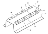
- FIG. 1 is a perspective view of a joint structure manufactured by the method for manufacturing a joint structure according to the present embodiment.
- the joint structure 10 includes a first plate-shaped member 11 made of steel, and a steel-made first plate-shaped member 11 formed as an elongated member narrower than the first plate-shaped member 11.
- both edges 12a along the longitudinal direction (X direction in the figure) of the second plate member 12 and the surface 11a of the first plate member 11 are formed by arc welding or laser-arc hybrid welding. They are joined by a metal (bead) 13.
- the weld metal (bead) 13 may be formed continuously along the both edges 12a or may be formed intermittently. However, as described later, when bending is performed along a virtual line B (see FIG. 2A) set on the overlapping surface 14, welding is performed to cope with the stress generated at the time of bending.
- the metal (bead) 13 is preferably formed continuously.
- the material of the first plate-like member 11 and the second plate-like member 12 made of steel is not particularly limited as long as it is pure iron and an iron alloy. For example, mild steel, carbon steel, stainless steel And so on.
- the first plate-like member 11 and the second plate-like member 12 are subjected to a surface treatment for forming a film such as an electric base element, a processed product, an insulating material, and a passivation for the purpose of preventing rust and the like. You can also. Examples include zinc plating, chromium plating, nickel plating, aluminum plating, tin (tin) plating, resin coating, and ceramic coating.
- Both edges 12a of the second plate-shaped member 12 and the surface 11a of the first plate-shaped member 11 are joined by a filler metal (welding wire) by arc welding or laser-arc hybrid welding. Therefore, for example, both edges 12a of the second plate-shaped member 12 can be joined with a wider area than when joining by spot welding, laser welding, or the like, and the joining strength is improved.
- a generally used welding wire or welding rod can be used as long as the welding metal 13 is an Fe-based alloy.
- the laser-arc hybrid welding is obtained by adding a laser as a heat source to an arc welding method as a heat source and a wire supply method. This method is advantageous in that the welding speed is higher than the ordinary arc welding method.
- both edges 12 a along the longitudinal direction of the second plate-shaped member 12 are welded to the first plate-shaped member 11 by arc welding or laser-arc hybrid welding.
- the edge 12b of the two plate-shaped member 12 extending in the direction intersecting both edges 12a (transverse direction) may also be welded to the first plate-shaped member 11 by arc welding or laser-arc hybrid welding.
- the first plate-like member 11 and the second plate-like member 12 welded by arc welding or laser-arc hybrid welding may be bent to form a molded product.
- Strength or bending strength may be insufficient.
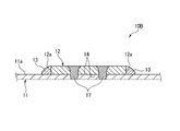
- the width of the second plate-shaped member 12 is large and the distance between both edges 12a is large, there is a concern about insufficient strength.
- FIG. 2A shows that the surface 11a of the first plate-shaped member 11 and both edges 12a of the second plate-shaped member 12 are joined by arc welding or laser-arc hybrid welding
- the first plate-shaped member 11 and the FIG. 10 is a perspective view of a joint structure 10A according to a modified example in which overlapping surfaces 14 with two plate members 12 are joined by laser welding.
- FIG. 2B is a sectional view taken along line AA of FIG. 2A.
- a joint structure 10A has a first plate in which both edges 12a are joined to the first plate-like member 11 by arc welding or laser-arc hybrid welding.
- the superposed surfaces 14 of the plate-like member 11 and the second plate-like member 12 are along the longitudinal direction (X direction in FIG. 2A) of the second plate-like member 12 by laser welding, and 12 are joined by a plurality of pairs of joining portions 15 formed facing each other in the width direction. Thereby, the joining strength between the first plate member 11 and the second plate member 12 is further improved.
- the joint structure 10A thus formed is bent along the imaginary line B (see FIG. 2A) set on the overlapping surface 14, and the bent portion 16 is formed. It is processed into the molded product 20 shown.
- the bent portion 16 (the imaginary line B) is set so as to pass through substantially the center of the pair of joining portions 15 formed to face each other in the width direction of the second plate-shaped member 12. As a result, the force acting at the time of bending is applied equally to the left and right, and the shape accuracy of the molded product 20 is improved.
- a shearing force acts on the joint between the first plate-shaped member 11 and the second plate-shaped member 12.
- first plate-like member 11 and the second plate-like member 12 are joined only by spot welding or laser welding, joining with the first plate-like member 11 at the edge 12a of the second plate-like member 12
- the strength may be weak, and the second plate-like member 12 may peel off from the edge 12a.
- the first plate-like member 11 and the second plate-like member 12 are joined by welding both edges 12a of the second plate-like member 12 by arc welding or laser-arc hybrid welding. Further, the overlapping surfaces 14 of the first plate-shaped member 11 and the second plate-shaped member 12 are joined at a plurality of positions by laser welding. Accordingly, the bonding strength is high, and the first plate-like member 11 and the second plate-like member 12 are prevented from peeling off due to bending.
- the first plate-like member 11 and the second plate-like member 12 are, for example, steel materials for hot stamping. It is preferred to use.
- the joining structures 10 and 10A are made of a steel material for hot stamping, bending is performed by hot stamping (hot working) that is performed while being heated to a temperature of 800 ° C or higher. This enables accurate molding.
- FIG. 4 shows that the overlapping surfaces 14 of the first plate-like member 11 and the second plate-like member 12 whose edges 12a are joined by arc welding or laser-arc hybrid welding are formed by plasma welding, TIG welding, or laser welding.
- -It is sectional drawing of the joining structure which concerns on another modification joined by TIG hybrid welding.
- both edges 12a of the first plate-shaped member 11 and the second plate-shaped member 12 are joined with a weld metal 13 by arc welding or laser-arc hybrid welding.
- the overlapping surfaces 14 of the plate-like member 11 and the second plate-like member 12 are firmly joined at a plurality of locations by a joint 17 by plasma welding, TIG welding, or laser / TIG hybrid welding.
- both edges 12a of the first plate-shaped member 11 and the second plate-shaped member 12 are joined to the first plate-shaped member 11 by arc welding or laser-arc hybrid welding. Since the overlapping surfaces 14 of the member 11 and the second plate-like member 12 are firmly joined at any of a plurality of locations by any of laser welding, plasma welding, TIG welding, and laser / TIG hybrid welding, hot stamping is performed. And can be suitably used as structural members for automobiles.
- the laser / TIG hybrid welding is obtained by adding a laser as a heat source to a TIG welding method as a heat source and a wire supply method. This method is advantageous in that it has a deeper penetration (penetration between two plates) and a higher welding speed than the ordinary TIG welding method.
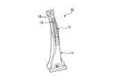
- FIG. 5 shows an example of a B pillar 30 (an example of a structural member for an automobile) manufactured by processing the joint structures 10, 10A, and 10B by hot stamping.
- the B pillar 30 is formed by joining a single second plate-shaped member 12 to a portion of the first plate-shaped member 11 where reinforcement is required by welding, and then integrally molding the same with a hot stamp.
- the two second plate-like members 12 are joined to the first plate-like member 11 at positions that become ridges of the B pillar 30, respectively.
- the second plate member 12 is formed by bending using a hot stamp on the overlapping surface 14.
- the present invention is not limited to the above-described embodiments and modified examples, and can be appropriately modified, improved, and the like.
- first plate-shaped member and the second plate-shaped member are further joined to each other within a plane of superposition of the first plate-shaped member and the second plate-shaped member (1).
- second plate-shaped member (1).
- the first plate-shaped member and the second plate-shaped member can be more firmly joined.
- the joining structure can be formed from an ultra-high strength steel plate.
- joint structure according to any one of (1) to (4), wherein the joint structure is an automobile structural member. According to this configuration, a joint structure that can be used as a structural member for an automobile can be manufactured.
- the first plate-like member and the second plate-like member may be laser-welded, plasma-welded, TIG-welded, and the like in a plane where the first plate-like member and the second plate-like member overlap.
- the joining structure can be formed from an ultra-high strength steel plate.
- First plate member (steel material for hot stamping) 11a Surface 12 Second plate member (steel material for hot stamping) 12a, 12b Edge 13 Weld metal (bead) 14 Overlapping surface 15 Joining section 16 Bending section 17 Joining section 20 Molded product (automobile structural member) 30 B pillar
Landscapes
- Engineering & Computer Science (AREA)
- Physics & Mathematics (AREA)
- Mechanical Engineering (AREA)
- Optics & Photonics (AREA)
- Plasma & Fusion (AREA)
- Chemical & Material Sciences (AREA)
- Combustion & Propulsion (AREA)
- Transportation (AREA)
- Body Structure For Vehicles (AREA)
- Laser Beam Processing (AREA)
- Arc Welding In General (AREA)
- Butt Welding And Welding Of Specific Article (AREA)
Abstract
高い接合強度を有し、かつ、低コストで製造可能な接合構造体及びその製造方法を提供する。鋼製の第1板状部材と、第1板状部材に重ねられ、長尺状に形成される鋼製の第2板状部材と、が接合されてなる接合構造体であって、第1板状部材の表面と第2板状部材の長手方向に沿った両縁部とが、溶接金属により接合される。
Description
本発明は、接合構造体及びその製造方法に関し、より詳細には、例えば、自動車用構造部材に好適な接合構造体及びその製造方法に関する。
近年、CO2排出量の削減を目的とした車体軽量化を図りつつ、衝突安全性の強化を実現するため、高張力鋼板を採用したり、必要箇所を補強材で部分的に補強する方法が知られている。特許文献1及び2には、2つの金属部材、すなわち第1金属部材と第2金属部材をレーザ溶接により接合して製造される接合体が開示されている。ここで、特許文献1には、レーザ溶接の溶接痕が一対又は複数対の互いに平行な直線であることが開示されている。また、特許文献2には、レーザ溶接の溶接痕が、連続して配置された複数のC字状部を有し、隣接するC状部の一部が重なることが開示されている。
特許文献1又は2に開示された接合体は、第1金属部材と第2金属部材の接合強度に依然として改善の余地がある。そのため、これらの接合体は、例えばホットスタンプ(熱間プレス)による加工に適さない。すなわち、これらの接合体をホットスタンプで加工すると、接合強度の不足、特に、第1金属部材と第2金属部材の縁部との接合部における接合強度不足により、縁部から第1金属部材と第2金属部材とが部分的又は全体的に剥離し得るおそれがある。
また、衝突事故時に上記ホットスタンプ部品に外力が加わると、第1金属部品と第2金属部品とが剥離し得るため、十分な補強効果を得ることができない。また、レーザ加工設備は、高価であるため、製品コストが増加する要因となっている。
また、衝突事故時に上記ホットスタンプ部品に外力が加わると、第1金属部品と第2金属部品とが剥離し得るため、十分な補強効果を得ることができない。また、レーザ加工設備は、高価であるため、製品コストが増加する要因となっている。
本発明は、前述した課題に鑑みてなされたものであり、その目的は、高い接合強度を有し、かつ、低コストで製造可能な接合構造体及びその製造方法を提供することにある。
本発明は、下記(1)の構成からなる。
(1) 鋼製の第1板状部材と、前記第1板状部材に重ねられ、長尺状に形成される鋼製の第2板状部材と、が接合されてなる接合構造体であって、
前記第1板状部材の表面と前記第2板状部材の長手方向に沿った両縁部とが、溶接金属により接合されることを特徴とする接合構造体。
(1) 鋼製の第1板状部材と、前記第1板状部材に重ねられ、長尺状に形成される鋼製の第2板状部材と、が接合されてなる接合構造体であって、
前記第1板状部材の表面と前記第2板状部材の長手方向に沿った両縁部とが、溶接金属により接合されることを特徴とする接合構造体。
また、本発明の好ましい実施形態は、下記(2)~(5)の構成からなる。
(2) 前記第1板状部材と前記第2板状部材との重ね合わせ面には、曲げ部が形成されることを特徴とする(1)に記載の接合構造体。
(3) 前記第1板状部材と前記第2板状部材との重ね合わせ面内において、前記第1板状部材と前記第2板状部材同士がさらに接合されることを特徴とする(1)又は(2)に記載の接合構造体。
(4) 前記第1板状部材及び前記第2板状部材の少なくとも一方は、ホットスタンプ用鋼材であることを特徴とする(1)~(3)のいずれかに記載の接合構造体。
(5) 前記接合構造体は、自動車用構造部材であることを特徴とする(1)~(4)のいずれかに記載の接合構造体。
(2) 前記第1板状部材と前記第2板状部材との重ね合わせ面には、曲げ部が形成されることを特徴とする(1)に記載の接合構造体。
(3) 前記第1板状部材と前記第2板状部材との重ね合わせ面内において、前記第1板状部材と前記第2板状部材同士がさらに接合されることを特徴とする(1)又は(2)に記載の接合構造体。
(4) 前記第1板状部材及び前記第2板状部材の少なくとも一方は、ホットスタンプ用鋼材であることを特徴とする(1)~(3)のいずれかに記載の接合構造体。
(5) 前記接合構造体は、自動車用構造部材であることを特徴とする(1)~(4)のいずれかに記載の接合構造体。
また、本発明は、下記(6)の構成からなる。
(6) 鋼製の第1板状部材と、前記第1板状部材に重ねられ、長尺状に形成される鋼製の第2板状部材と、が接合されてなる接合構造体の製造方法であって、
前記第1板状部材と前記第2板状部材とを重ね合わせる工程と、
前記第2板状部材の長手方向に沿った両縁部を、それぞれアーク溶接またはレーザ・アークハイブリッド溶接によって前記第1板状部材に接合する溶接工程と、
を備えることを特徴とする接合構造体の製造方法。
(6) 鋼製の第1板状部材と、前記第1板状部材に重ねられ、長尺状に形成される鋼製の第2板状部材と、が接合されてなる接合構造体の製造方法であって、
前記第1板状部材と前記第2板状部材とを重ね合わせる工程と、
前記第2板状部材の長手方向に沿った両縁部を、それぞれアーク溶接またはレーザ・アークハイブリッド溶接によって前記第1板状部材に接合する溶接工程と、
を備えることを特徴とする接合構造体の製造方法。
また、本発明の好ましい実施形態は、下記(7)~(10)の構成からなる。
(7) 前記第1板状部材と前記第2板状部材との重ね合わせ面上で、曲げ加工することを特徴とする(6)に記載の接合構造体の製造方法。
(8) 前記第1板状部材と前記第2板状部材との重ね合わせ面内において、前記第1板状部材と前記第2板状部材同士が、レーザ溶接、プラズマ溶接、TIG溶接、及びレーザ・TIGハイブリッド溶接のいずれかの溶接によりさらに接合されることを特徴とする(6)又は(7)に記載の接合構造体の製造方法。
(9) 前記第1板状部材及び前記第2板状部材の少なくとも一方は、ホットスタンプ用鋼材であることを特徴とする(6)~(8)のいずれかに記載の接合構造体の製造方法。
(10) 前記接合構造体は、自動車用構造部材であることを特徴とする(6)~(9)のいずれかに記載の接合構造体の製造方法。
本発明の接合構造体及びその製造方法によれば、接合構造体が高い接合強度を有し、かつ、該接合構造体を低コストで製造することができる。
以下、本発明に係る接合構造体の一実施形態を図面に基づいて詳細に説明する。
図1は、本実施形態に係る接合構造体の製造方法によって製造された接合構造体の斜視図である。図1に示すように、接合構造体10は、鋼製の第1板状部材11と、第1板状部材11より幅狭の長尺状に形成された、補強材としての鋼製の第2板状部材12と、を備える。
図1は、本実施形態に係る接合構造体の製造方法によって製造された接合構造体の斜視図である。図1に示すように、接合構造体10は、鋼製の第1板状部材11と、第1板状部材11より幅狭の長尺状に形成された、補強材としての鋼製の第2板状部材12と、を備える。
第2板状部材12は、第1板状部材11の表面11a上に重ね合わされている。そして、第2板状部材12の長手方向(図中、X方向)に沿う両縁部12aと第1板状部材11の表面11aとが、アーク溶接またはレーザ・アークハイブリッド溶接によって形成される溶接金属(ビード)13によって接合されている。なお、溶接金属(ビード)13は、両縁部12aに沿って連続形成されても、断続形成されてもよい。しかし、後述するように、重ね合わせ面14上に設定された仮想線B(図2Aを参照)に沿って曲げ加工が施される場合には、曲げ加工時に発生する応力に対応するため、溶接金属(ビード)13は連続で形成されるのが好ましい。
なお、鋼製である、第1板状部材11及び第2板状部材12の材質は、純鉄および鉄合金であれば、特に制限されるものでなく、例えば、軟鋼、炭素鋼、ステンレス鋼などがあげられる。
また、第1板状部材11及び第2板状部材12には、錆防止等を目的として、電気的卑の元素や加工物、絶縁性物質、不動態といった皮膜を形成する表面処理を施すこともできる。例えば、亜鉛めっき、クロムめっき、ニッケルめっき、アルミめっき、錫(すず)めっき、樹脂塗装、セラミックコーティングなどがあげられる。
また、第1板状部材11及び第2板状部材12には、錆防止等を目的として、電気的卑の元素や加工物、絶縁性物質、不動態といった皮膜を形成する表面処理を施すこともできる。例えば、亜鉛めっき、クロムめっき、ニッケルめっき、アルミめっき、錫(すず)めっき、樹脂塗装、セラミックコーティングなどがあげられる。
第2板状部材12の両縁部12aと第1板状部材11の表面11aとは、アーク溶接またはレーザ・アークハイブリッド溶接による溶加材(溶接ワイヤ)で接合される。よって、例えば、スポット溶接やレーザ溶接などによる接合と比較して、広い面積で、かつ、第2板状部材12の両縁部12aを接合することができ、接合強度が向上する。また、溶加材の成分を適宜選択することで、接合部における接合強度設計が可能となる。溶加材の材質については、溶接金属13がFe系合金となるものであれば、一般的に用いられる溶接用ワイヤまたは溶接棒が適用可能である。
なお、レーザ・アークハイブリッド溶接は、熱源およびワイヤ供給法としてのアーク溶接法に、熱源としてレーザを加えたものである。この方法は、通常のアーク溶接法に比べ、溶接速度が高い点で有利である。
なお、レーザ・アークハイブリッド溶接は、熱源およびワイヤ供給法としてのアーク溶接法に、熱源としてレーザを加えたものである。この方法は、通常のアーク溶接法に比べ、溶接速度が高い点で有利である。
また、図1に示す実施形態では、第2板状部材12の長手方向に沿う両縁部12aが、アーク溶接またはレーザ・アークハイブリッド溶接によって第1板状部材11に溶接されているが、第2板状部材12の両縁部12aに交差する方向(短手方向)に延びる縁部12bも、アーク溶接またはレーザ・アークハイブリッド溶接によって第1板状部材11と溶接してもよい。このように、第2板状部材12を縁部12a,12bの全周に渡って第1板状部材11と溶接することにより、第1板状部材11と第2板状部材12との隙間に侵入する水などを防止することができ、耐食性が大幅に向上する。
アーク溶接またはレーザ・アークハイブリッド溶接によって溶接された第1板状部材11及び第2板状部材12は、成形品にするため曲げ加工される場合がある。曲げ加工の程度や接合構造体10に要求される強度によっては、第2板状部材12の両縁部12aのみが、アーク溶接またはレーザ・アークハイブリッド溶接によって溶接された接合構造体10では、接合強度や曲げ強度が不足する場合がある。特に、第2板状部材12の幅が広く、両縁部12a間の距離が大きい場合、強度不足が懸念される。
図2Aは、第1板状部材11の表面11aと、第2板状部材12の両縁部12aとが、アーク溶接またはレーザ・アークハイブリッド溶接によって接合され、さらに第1板状部材11と第2板状部材12との重ね合わせ面14同士が、レーザ溶接により接合された変形例に係る接合構造体10Aの斜視図である。また、図2Bは、図2AのA-A線における断面図である。
本変形例に係る接合構造体10Aは、図2A及び図2Bに示すように、アーク溶接またはレーザ・アークハイブリッド溶接によって、両縁部12aが第1板状部材11に接合された、第1板状部材11と第2板状部材12との重ね合わせ面14同士が、レーザ溶接により、第2板状部材12の長手方向(図2A中、X方向)に沿い、かつ、第2板状部材12の幅方向に対向して形成された複数対の接合部15によって接合されている。これにより、第1板状部材11と第2板状部材12との接合強度がさらに向上する。
このように形成された接合構造体10Aは、重ね合わせ面14上に設定された仮想線B(図2Aを参照)に沿って曲げ加工され、曲げ部16が形成されることで、図3に示す成形品20に加工される。
なお、曲げ部16(仮想線B)は、第2板状部材12の幅方向に対向して形成された一対の接合部15の略中央を通るように設定されることが好ましい。これにより、曲げ成形時に作用する力が左右均等に作用して、成形品20の形状精度が向上する。
曲げ加工に伴って、第1板状部材11と第2板状部材12との接合部には、せん断力が作用する。第1板状部材11と第2板状部材12とが、スポット溶接やレーザ溶接のみによって接合されている場合、第2板状部材12の縁部12aにおける、第1板状部材11との接合強度が弱いおそれがあり、該縁部12aから第2板状部材12が剥離する可能性がある。
しかし、本実施形態の接合構造体10Aでは、第1板状部材11及び第2板状部材12は、第2板状部材12の両縁部12aが、アーク溶接またはレーザ・アークハイブリッド溶接によって接合され、さらに第1板状部材11と第2板状部材12との重ね合わせ面14同士が、レーザ溶接により複数個所で接合されている。よって、接合強度が強く、曲げ加工により第1板状部材11と第2板状部材12とが剥離することが防止される。
接合構造体10,10Aが、例えば、ピラーなどの高強度が要求される自動車用構造部材である場合、第1板状部材11及び第2板状部材12としては、例えば、ホットスタンプ用鋼材を使用するのが好ましい。接合構造体10,10Aがホットスタンプ用鋼材で構成される場合、曲げ加工は、800℃以上の温度に加熱した状態で加工されるホットスタンプ(熱間加工)により行われる。これにより、精度のよい成形が可能となる。
図4は、縁部12aがアーク溶接またはレーザ・アークハイブリッド溶接により接合された第1板状部材11と第2板状部材12との重ね合わせ面14同士が、プラズマ溶接、TIG溶接、またはレーザ・TIGハイブリッド溶接により接合された他の変形例に係る接合構造体の断面図である。
本変形例の接合構造体10Bは、第1板状部材11と第2板状部材12の両縁部12aとが、アーク溶接またはレーザ・アークハイブリッド溶接による溶接金属13で接合され、さらに第1板状部材11と第2板状部材12との重ね合わせ面14同士が、複数個所において、プラズマ溶接、TIG溶接、またはレーザ・TIGハイブリッド溶接による接合部17によって強固に接合されている。
このように、第1板状部材11と第2板状部材12とは、両縁部12aが、アーク溶接またはレーザ・アークハイブリッド溶接により第1板状部材11に接合され、さらに第1板状部材11と第2板状部材12の重ね合わせ面14同士が、複数個所において、レーザ溶接、プラズマ溶接、TIG溶接、及びレーザ・TIGハイブリッド溶接のいずれかにより強固に接合されているので、ホットスタンプによる成形加工が可能となり、自動車用構造部材として好適に使用される。
なお、レーザ・TIGハイブリッド溶接は、熱源およびワイヤ供給法としてのTIG溶接法に、熱源としてレーザを加えたものである。この方法は、通常のTIG溶接法に比べ、溶け込み(2枚板の貫通性)が深く、また、溶接速度が高い点で有利である。
なお、レーザ・TIGハイブリッド溶接は、熱源およびワイヤ供給法としてのTIG溶接法に、熱源としてレーザを加えたものである。この方法は、通常のTIG溶接法に比べ、溶け込み(2枚板の貫通性)が深く、また、溶接速度が高い点で有利である。
例えば、図5は、接合構造体10,10A,10Bをホットスタンプで加工して製造したBピラー30(自動車用構造部材の一例)の一例を示す。このBピラー30は、第1板状部材11における補強が必要部位に、1枚の第2板状部材12を溶接で接合した後、ホットスタンプで一体成形して形成されている。
また、図6に示すBピラー30は、2枚の第2板状部材12が、それぞれBピラー30の稜線部となる位置で第1板状部材11に接合され、第1板状部材11及び第2板状部材12の重ね合わせ面14においてホットスタンプにより曲げ加工されて形成されている。
なお、接合構造体10,10A,10Bが適用可能な自動車用構造部材としては、Bピラー30以外にも、サイドシル、フロアクロスメンバ、ルーフサイドレール、センタートンネルカバーなどが例示される。
なお、本発明は、前述した実施形態及び変形例に限定されるものではなく、適宜、変形、改良、等が可能である。
以上の通り、本明細書には次の事項が開示されている。
(1) 鋼製の第1板状部材と、前記第1板状部材に重ねられ、長尺状に形成される鋼製の第2板状部材と、が接合されてなる接合構造体であって、
前記第1板状部材の表面と前記第2板状部材の長手方向に沿った両縁部とが、溶接金属により接合されることを特徴とする接合構造体。
この構成によれば、高い接合強度を有する接合構造体を低コストで製造できる。
(1) 鋼製の第1板状部材と、前記第1板状部材に重ねられ、長尺状に形成される鋼製の第2板状部材と、が接合されてなる接合構造体であって、
前記第1板状部材の表面と前記第2板状部材の長手方向に沿った両縁部とが、溶接金属により接合されることを特徴とする接合構造体。
この構成によれば、高い接合強度を有する接合構造体を低コストで製造できる。
(2) 前記第1板状部材と前記第2板状部材との重ね合わせ面には、曲げ部が形成されることを特徴とする(1)に記載の接合構造体。
この構成によれば、第1板状部材と第2板状部材とが溶接により接合された接合構造体を曲げ加工して、強度補強された成形品を製造できる。
できる。
この構成によれば、第1板状部材と第2板状部材とが溶接により接合された接合構造体を曲げ加工して、強度補強された成形品を製造できる。
できる。
(3) 前記第1板状部材と前記第2板状部材との重ね合わせ面内において、前記第1板状部材と前記第2板状部材同士がさらに接合されることを特徴とする(1)又は(2)に記載の接合構造体。
この構成によれば、第1板状部材と第2板状部材とを、さらに強固に接合することができる。
この構成によれば、第1板状部材と第2板状部材とを、さらに強固に接合することができる。
(4) 前記第1板状部材及び前記第2板状部材の少なくとも一方は、ホットスタンプ用鋼材であることを特徴とする(1)~(3)のいずれかに記載の接合構造体。
この構成によれば、接合構造体を超高強度鋼板で形成することができる。
この構成によれば、接合構造体を超高強度鋼板で形成することができる。
(5) 前記接合構造体は、自動車用構造部材であることを特徴とする(1)~(4)のいずれかに記載の接合構造体。
この構成によれば、自動車用構造部材として使用可能な接合構造体が製造できる。
この構成によれば、自動車用構造部材として使用可能な接合構造体が製造できる。
(6) 鋼製の第1板状部材と、前記第1板状部材に重ねられ、長尺状に形成される鋼製の第2板状部材と、が接合されてなる接合構造体の製造方法であって、
前記第1板状部材と前記第2板状部材とを重ね合わせる工程と、
前記第2板状部材の長手方向に沿った両縁部を、それぞれアーク溶接またはレーザ・アークハイブリッド溶接によって前記第1板状部材に接合する溶接工程と、
を備えることを特徴とする接合構造体の製造方法。
この構成によれば、第1板状部材と第2板状部材とを、アーク溶接またはレーザ・アークハイブリッド溶接によって接合することで、接合強度の高い接合構造体を低コストで製造することができる。
前記第1板状部材と前記第2板状部材とを重ね合わせる工程と、
前記第2板状部材の長手方向に沿った両縁部を、それぞれアーク溶接またはレーザ・アークハイブリッド溶接によって前記第1板状部材に接合する溶接工程と、
を備えることを特徴とする接合構造体の製造方法。
この構成によれば、第1板状部材と第2板状部材とを、アーク溶接またはレーザ・アークハイブリッド溶接によって接合することで、接合強度の高い接合構造体を低コストで製造することができる。
(7) 前記第1板状部材と前記第2板状部材との重ね合わせ面上で、曲げ加工することを特徴とする(6)に記載の接合構造体の製造方法。
この構成によれば、第1板状部材と第2板状部材とが溶接により接合された接合構造体を曲げ加工して、強度補強された成形品を製造できる。
この構成によれば、第1板状部材と第2板状部材とが溶接により接合された接合構造体を曲げ加工して、強度補強された成形品を製造できる。
(8) 前記第1板状部材と前記第2板状部材との重ね合わせ面内において、前記第1板状部材と前記第2板状部材同士が、レーザ溶接、プラズマ溶接、TIG溶接、及びレーザ・TIGハイブリッド溶接のいずれかの溶接によりさらに接合されることを特徴とする(6)又は(7)に記載の接合構造体の製造方法。
この構成によれば、第1板状部材と第2板状部材とを、さらに強固に接合することができる。
この構成によれば、第1板状部材と第2板状部材とを、さらに強固に接合することができる。
(9) 前記第1板状部材及び前記第2板状部材の少なくとも一方は、ホットスタンプ用鋼材であることを特徴とする(6)~(8)のいずれかに記載の接合構造体の製造方法。
この構成によれば、接合構造体を超高強度鋼板で形成することができる。
この構成によれば、接合構造体を超高強度鋼板で形成することができる。
(10) 前記接合構造体は、自動車用構造部材であることを特徴とする(6)~(9)のいずれかに記載の接合構造体の製造方法。
この構成によれば、自動車用構造部材として使用可能な接合構造体が製造できる。
この構成によれば、自動車用構造部材として使用可能な接合構造体が製造できる。
以上、図面を参照しながら各種の実施の形態について説明したが、本発明はかかる例に限定されないことは言うまでもない。当業者であれば、特許請求の範囲に記載された範疇内において、各種の変更例又は修正例に想到し得ることは明らかであり、それらについても当然に本発明の技術的範囲に属するものと了解される。また、発明の趣旨を逸脱しない範囲において、上記実施の形態における各構成要素を任意に組み合わせてもよい。
なお、本出願は、2018年6月29日出願の日本特許出願(特願2018-124515)に基づくものであり、その内容は本出願の中に参照として援用される。
10,10A,10B 接合構造体
11 第1板状部材(ホットスタンプ用鋼材)
11a 表面
12 第2板状部材(ホットスタンプ用鋼材)
12a,12b 縁部
13 溶接金属(ビード)
14 重ね合わせ面
15 接合部
16 曲げ部
17 接合部
20 成形品(自動車用構造部材)
30 Bピラー
11 第1板状部材(ホットスタンプ用鋼材)
11a 表面
12 第2板状部材(ホットスタンプ用鋼材)
12a,12b 縁部
13 溶接金属(ビード)
14 重ね合わせ面
15 接合部
16 曲げ部
17 接合部
20 成形品(自動車用構造部材)
30 Bピラー
Claims (10)
- 鋼製の第1板状部材と、前記第1板状部材に重ねられ、長尺状に形成される鋼製の第2板状部材と、が接合されてなる接合構造体であって、
前記第1板状部材の表面と前記第2板状部材の長手方向に沿った両縁部とが、溶接金属により接合されることを特徴とする接合構造体。 - 前記第1板状部材と前記第2板状部材との重ね合わせ面には、曲げ部が形成されることを特徴とする請求項1に記載の接合構造体。
- 前記第1板状部材と前記第2板状部材との重ね合わせ面内において、前記第1板状部材と前記第2板状部材同士がさらに接合されることを特徴とする請求項1又は2に記載の接合構造体。
- 前記第1板状部材及び前記第2板状部材の少なくとも一方は、ホットスタンプ用鋼材であることを特徴とする請求項1又は2に記載の接合構造体。
- 前記接合構造体は、自動車用構造部材であることを特徴とする請求項1又は2に記載の接合構造体。
- 鋼製の第1板状部材と、前記第1板状部材に重ねられ、長尺状に形成される鋼製の第2板状部材と、が接合されてなる接合構造体の製造方法であって、
前記第1板状部材と前記第2板状部材とを重ね合わせる工程と、
前記第2板状部材の長手方向に沿った両縁部を、それぞれアーク溶接またはレーザ・アークハイブリッド溶接によって前記第1板状部材に接合する溶接工程と、
を備えることを特徴とする接合構造体の製造方法。 - 前記第1板状部材と前記第2板状部材との重ね合わせ面上で、曲げ加工することを特徴とする請求項6に記載の接合構造体の製造方法。
- 前記第1板状部材と前記第2板状部材との重ね合わせ面内において、前記第1板状部材と前記第2板状部材同士が、レーザ溶接、プラズマ溶接、TIG溶接、及びレーザ・TIGハイブリッド溶接のいずれかの溶接によりさらに接合されることを特徴とする請求項6又は7に記載の接合構造体の製造方法。
- 前記第1板状部材及び前記第2板状部材の少なくとも一方は、ホットスタンプ用鋼材であることを特徴とする請求項6又は7に記載の接合構造体の製造方法。
- 前記接合構造体は、自動車用構造部材であることを特徴とする請求項6又は7に記載の接合構造体の製造方法。
Priority Applications (5)
| Application Number | Priority Date | Filing Date | Title |
|---|---|---|---|
| CN201980040804.5A CN112313026A (zh) | 2018-06-29 | 2019-05-31 | 接合结构体及其制造方法 |
| EP19825575.4A EP3797913B1 (en) | 2018-06-29 | 2019-05-31 | Joining structure and method for manufacturing the same |
| US17/256,499 US20210276126A1 (en) | 2018-06-29 | 2019-05-31 | Joining structure and method for manufacturing same |
| ES19825575T ES2970634T3 (es) | 2018-06-29 | 2019-05-31 | Estructura de unión y método para fabricar la misma |
| US18/323,903 US20230294205A1 (en) | 2018-06-29 | 2023-05-25 | Joining structure and method for manufacturing same |
Applications Claiming Priority (2)
| Application Number | Priority Date | Filing Date | Title |
|---|---|---|---|
| JP2018-124515 | 2018-06-29 | ||
| JP2018124515A JP7181016B2 (ja) | 2018-06-29 | 2018-06-29 | 接合構造体及びその製造方法 |
Related Child Applications (2)
| Application Number | Title | Priority Date | Filing Date |
|---|---|---|---|
| US17/256,499 A-371-Of-International US20210276126A1 (en) | 2018-06-29 | 2019-05-31 | Joining structure and method for manufacturing same |
| US18/323,903 Division US20230294205A1 (en) | 2018-06-29 | 2023-05-25 | Joining structure and method for manufacturing same |
Publications (1)
| Publication Number | Publication Date |
|---|---|
| WO2020003900A1 true WO2020003900A1 (ja) | 2020-01-02 |
Family
ID=68985008
Family Applications (1)
| Application Number | Title | Priority Date | Filing Date |
|---|---|---|---|
| PCT/JP2019/021881 WO2020003900A1 (ja) | 2018-06-29 | 2019-05-31 | 接合構造体及びその製造方法 |
Country Status (6)
| Country | Link |
|---|---|
| US (2) | US20210276126A1 (ja) |
| EP (1) | EP3797913B1 (ja) |
| JP (1) | JP7181016B2 (ja) |
| CN (1) | CN112313026A (ja) |
| ES (1) | ES2970634T3 (ja) |
| WO (1) | WO2020003900A1 (ja) |
Cited By (2)
| Publication number | Priority date | Publication date | Assignee | Title |
|---|---|---|---|---|
| WO2022171665A1 (en) | 2021-02-11 | 2022-08-18 | Autotech Engineering S.L. | Structural members for a vehicle and methods |
| EP4122617A4 (en) * | 2020-03-16 | 2024-01-10 | Nippon Steel Corp | STEEL COMPONENT AND ITS MANUFACTURING METHOD |
Families Citing this family (5)
| Publication number | Priority date | Publication date | Assignee | Title |
|---|---|---|---|---|
| US11351590B2 (en) | 2017-08-10 | 2022-06-07 | Honda Motor Co., Ltd. | Features of dissimilar material-reinforced blanks and extrusions for forming |
| US10532421B2 (en) * | 2017-08-29 | 2020-01-14 | Honda Motor Co., Ltd. | UAM resistance spot weld joint transition for multimaterial automotive structures |
| US10870166B2 (en) | 2018-02-01 | 2020-12-22 | Honda Motor Co., Ltd. | UAM transition for fusion welding of dissimilar metal parts |
| US11465390B2 (en) | 2020-03-02 | 2022-10-11 | Honda Motor Co., Ltd. | Post-process interface development for metal-matrix composites |
| WO2022080172A1 (ja) | 2020-10-12 | 2022-04-21 | 日本製鉄株式会社 | 長尺構造部材、及びブランク材 |
Citations (6)
| Publication number | Priority date | Publication date | Assignee | Title |
|---|---|---|---|---|
| JP2001507993A (ja) | 1997-01-14 | 2001-06-19 | コスマ パワーレーザーズ リミテッド | テイラードブランク |
| JP2002160020A (ja) * | 2000-11-28 | 2002-06-04 | Sumitomo Metal Ind Ltd | 自動車車体用接合金属帯およびその製造法 |
| JP2013220445A (ja) * | 2012-04-17 | 2013-10-28 | Nippon Steel & Sumitomo Metal Corp | ホットスタンプ用のテーラードブランクとその製造方法 |
| JP2014015206A (ja) | 2010-09-16 | 2014-01-30 | Nippon Steel & Sumitomo Metal | 成形部材およびその製造方法 |
| JP2017189781A (ja) * | 2016-04-11 | 2017-10-19 | 新日鐵住金株式会社 | テーラードブランク成形材 |
| JP2018124515A (ja) | 2017-02-03 | 2018-08-09 | Kddi株式会社 | コンピュータプログラム、端末および方法 |
Family Cites Families (10)
| Publication number | Priority date | Publication date | Assignee | Title |
|---|---|---|---|---|
| US5603853A (en) * | 1995-02-28 | 1997-02-18 | The Twentyfirst Century Corporation | Method of high energy density radiation beam lap welding |
| JP3362624B2 (ja) * | 1997-01-10 | 2003-01-07 | 日本鋼管株式会社 | 重ね溶接継手の疲労特性向上方法 |
| JP2000197969A (ja) * | 1998-12-25 | 2000-07-18 | Sumitomo Metal Ind Ltd | 一体化成形用ブランクおよびその成形方法 |
| DE10104468A1 (de) * | 2001-02-02 | 2002-08-29 | Eberspaecher J Gmbh & Co | Platine für ein Abgas-Gehäuseteil eines Kraftfahrzeugs sowie Verfahren zur Herstellung des Abgas-Gehäuseteils |
| JP2003268804A (ja) * | 2002-03-15 | 2003-09-25 | Hitachi Constr Mach Co Ltd | 建設機械の構成部材の補強装置及びその補強方法 |
| JP2011088484A (ja) * | 2009-10-20 | 2011-05-06 | Toyota Motor Corp | 車両用骨格部材及びその製造方法 |
| CN203649731U (zh) * | 2013-12-08 | 2014-06-18 | 中国石油天然气第一建设公司 | 一种储罐施工搭接板限位器 |
| JP6168077B2 (ja) * | 2015-02-12 | 2017-07-26 | Jfeスチール株式会社 | プレス成形部品の接合構造、該接合構造を有する自動車用構造部品及び接合部品の製造方法 |
| EP3409410B1 (en) * | 2016-01-28 | 2022-01-05 | Nippon Steel Corporation | Method for improving fatigue strength of lap-welded joint, lap-welded joint manufacturing method, and lap-welded joint |
| JP2018075612A (ja) * | 2016-11-10 | 2018-05-17 | トヨタ自動車株式会社 | 曲げ加工部材及びその製造方法 |
-
2018
- 2018-06-29 JP JP2018124515A patent/JP7181016B2/ja active Active
-
2019
- 2019-05-31 CN CN201980040804.5A patent/CN112313026A/zh active Pending
- 2019-05-31 ES ES19825575T patent/ES2970634T3/es active Active
- 2019-05-31 US US17/256,499 patent/US20210276126A1/en active Pending
- 2019-05-31 EP EP19825575.4A patent/EP3797913B1/en active Active
- 2019-05-31 WO PCT/JP2019/021881 patent/WO2020003900A1/ja unknown
-
2023
- 2023-05-25 US US18/323,903 patent/US20230294205A1/en active Pending
Patent Citations (6)
| Publication number | Priority date | Publication date | Assignee | Title |
|---|---|---|---|---|
| JP2001507993A (ja) | 1997-01-14 | 2001-06-19 | コスマ パワーレーザーズ リミテッド | テイラードブランク |
| JP2002160020A (ja) * | 2000-11-28 | 2002-06-04 | Sumitomo Metal Ind Ltd | 自動車車体用接合金属帯およびその製造法 |
| JP2014015206A (ja) | 2010-09-16 | 2014-01-30 | Nippon Steel & Sumitomo Metal | 成形部材およびその製造方法 |
| JP2013220445A (ja) * | 2012-04-17 | 2013-10-28 | Nippon Steel & Sumitomo Metal Corp | ホットスタンプ用のテーラードブランクとその製造方法 |
| JP2017189781A (ja) * | 2016-04-11 | 2017-10-19 | 新日鐵住金株式会社 | テーラードブランク成形材 |
| JP2018124515A (ja) | 2017-02-03 | 2018-08-09 | Kddi株式会社 | コンピュータプログラム、端末および方法 |
Cited By (2)
| Publication number | Priority date | Publication date | Assignee | Title |
|---|---|---|---|---|
| EP4122617A4 (en) * | 2020-03-16 | 2024-01-10 | Nippon Steel Corp | STEEL COMPONENT AND ITS MANUFACTURING METHOD |
| WO2022171665A1 (en) | 2021-02-11 | 2022-08-18 | Autotech Engineering S.L. | Structural members for a vehicle and methods |
Also Published As
| Publication number | Publication date |
|---|---|
| EP3797913A4 (en) | 2021-08-18 |
| ES2970634T3 (es) | 2024-05-29 |
| CN112313026A (zh) | 2021-02-02 |
| JP2020001076A (ja) | 2020-01-09 |
| JP7181016B2 (ja) | 2022-11-30 |
| EP3797913B1 (en) | 2024-01-31 |
| EP3797913A1 (en) | 2021-03-31 |
| US20230294205A1 (en) | 2023-09-21 |
| US20210276126A1 (en) | 2021-09-09 |
Similar Documents
| Publication | Publication Date | Title |
|---|---|---|
| WO2020003900A1 (ja) | 接合構造体及びその製造方法 | |
| KR101710851B1 (ko) | 중첩부의 용접 방법 및 겹침 용접 부재 | |
| JP6651308B2 (ja) | 構造体構成部材及び構造体構成部材を製造する方法 | |
| US9102357B2 (en) | Side outer panel for vehicle | |
| US8276954B2 (en) | Bumper system | |
| JP5955370B2 (ja) | 金属接合体の製造方法 | |
| US10532421B2 (en) | UAM resistance spot weld joint transition for multimaterial automotive structures | |
| CN108136528B (zh) | 角焊方法和角焊接头 | |
| US20050244667A1 (en) | Hybrid-produced sheet metal element and method of producing same | |
| EP2911822B1 (en) | Laser metal deposition welding of automotive parts | |
| KR20150121709A (ko) | 자동차용 구조 부재 및 그 제조 방법 | |
| US11383329B2 (en) | Method for producing a workpiece composite, and workpiece composite | |
| WO2013008805A1 (ja) | ドアサッシュ | |
| JP2014184950A (ja) | 構造体の連結部材 | |
| JP2009000728A (ja) | 異種金属の接合方法及び接合構造 | |
| DE50303409D1 (de) | Verfahren zum fügen zweier bleche einerseits aus einem aluminiumwerkstoff und anderseits aus einem eisen- oder titanwerkstoff durch eine schweiss-lötverbindung | |
| JP6939468B2 (ja) | 車両構造材 | |
| WO2023032740A1 (ja) | バッテリーケース及びバッテリーケースの製造方法 | |
| US20140062132A1 (en) | Impact Beam | |
| US20220176486A1 (en) | Joint structure, automotive component, and joint structure manufacturing method | |
| JP5027519B2 (ja) | 車体パネルの結合部の構造 | |
| EP3978177A1 (en) | Method for manufacturing heterometallic complex and heterometallic complex | |
| JP7325021B2 (ja) | 接合構造及び接合方法 | |
| JP6638983B2 (ja) | パイプ部品 | |
| JP4993473B2 (ja) | 自動車クロージャー部品の製造方法 |
Legal Events
| Date | Code | Title | Description |
|---|---|---|---|
| 121 | Ep: the epo has been informed by wipo that ep was designated in this application |
Ref document number: 19825575 Country of ref document: EP Kind code of ref document: A1 |
|
| NENP | Non-entry into the national phase |
Ref country code: DE |
|
| ENP | Entry into the national phase |
Ref document number: 2019825575 Country of ref document: EP Effective date: 20201222 |