WO2020003726A1 - コンクリート段差部用型枠ユニットおよびコンクリート構造物施工方法 - Google Patents
コンクリート段差部用型枠ユニットおよびコンクリート構造物施工方法 Download PDFInfo
- Publication number
- WO2020003726A1 WO2020003726A1 PCT/JP2019/017610 JP2019017610W WO2020003726A1 WO 2020003726 A1 WO2020003726 A1 WO 2020003726A1 JP 2019017610 W JP2019017610 W JP 2019017610W WO 2020003726 A1 WO2020003726 A1 WO 2020003726A1
- Authority
- WO
- WIPO (PCT)
- Prior art keywords
- concrete
- panel
- buried
- unit
- formwork
- Prior art date
Links
Images


Classifications
-
- E—FIXED CONSTRUCTIONS
- E04—BUILDING
- E04B—GENERAL BUILDING CONSTRUCTIONS; WALLS, e.g. PARTITIONS; ROOFS; FLOORS; CEILINGS; INSULATION OR OTHER PROTECTION OF BUILDINGS
- E04B2/00—Walls, e.g. partitions, for buildings; Wall construction with regard to insulation; Connections specially adapted to walls
- E04B2/84—Walls made by casting, pouring, or tamping in situ
- E04B2/86—Walls made by casting, pouring, or tamping in situ made in permanent forms
-
- E—FIXED CONSTRUCTIONS
- E04—BUILDING
- E04G—SCAFFOLDING; FORMS; SHUTTERING; BUILDING IMPLEMENTS OR AIDS, OR THEIR USE; HANDLING BUILDING MATERIALS ON THE SITE; REPAIRING, BREAKING-UP OR OTHER WORK ON EXISTING BUILDINGS
- E04G17/00—Connecting or other auxiliary members for forms, falsework structures, or shutterings
- E04G17/06—Tying means; Spacers ; Devices for extracting or inserting wall ties
-
- E—FIXED CONSTRUCTIONS
- E04—BUILDING
- E04G—SCAFFOLDING; FORMS; SHUTTERING; BUILDING IMPLEMENTS OR AIDS, OR THEIR USE; HANDLING BUILDING MATERIALS ON THE SITE; REPAIRING, BREAKING-UP OR OTHER WORK ON EXISTING BUILDINGS
- E04G9/00—Forming or shuttering elements for general use
Definitions
- the present invention relates to a formwork unit used to form a concrete structure having a step, and a method for constructing a concrete structure.
- a formwork for defining the filling range of the concrete raw material is often formed by assembling a plurality of panels that are removed from the concrete structure after construction.
- Techniques related to such a concrete casting formwork are described in, for example, Patent Documents 1 to 3 below.
- the concrete structure to be formed has a step structure between one upward surface (first upward surface) and another upward surface (second upward surface) higher than this
- the concrete structure The required number of panels forming the formwork assembled during the construction process of the structure includes a panel for defining a side wall surface between two upward surfaces in the step structure.
- the side wall surface defining panel is located at a height higher than the height position where the first upward surface of the stepped concrete structure is formed.
- the panel is assembled in such a manner that the lower end of the panel is located at the upper position (that is, a predetermined interval is provided between the height position of the first upward surface to be formed and the lower end of the side wall surface defining panel). In this manner, the panel is assembled.
- the first upward surface of the concrete structure with a stepped portion is located at a height position where it should be originally formed. Partial leakage of the unhardened concrete from between the lower end of the side wall defining panel, ie, overflow, occurs. Then, at the boundary between the first upward surface and the side wall surface, the protruding concrete hardens, and an extra portion such as an extra inclined portion is formed in comparison with the original corner shape (first). An appropriate corner shape is not formed at the boundary between the upward surface and the side wall surface).
- the panel is conventionally temporarily assembled by simple means in some cases.
- the panel is likely to be distorted due to a load such as a self-weight or an impact load of the concrete raw material supplied and flowing in the section including the side wall surface defining panel by the formwork. If the assembled side wall surface defining panel is distorted, a side wall surface that is displaced from the expected formation position is formed. It is necessary to repair the side wall surface which is displaced, and such repair is undesirable because it increases the work, time, and cost required for constructing the concrete structure with the stepped portion.
- the present invention has been conceived under such circumstances, and an object thereof is to provide a form unit and a construction method suitable for efficiently forming a concrete structure having a step structure. It is in.
- a form unit for a concrete step portion includes at least one embedded panel, at least one bolt, and at least one fixture.
- a formwork unit can be used to form a formwork for the construction of a concrete structure with a stepped portion, such as a concrete wall with a rising step in a so-called water return portion, a concrete floor with a predetermined stepped structure, and the like. Things.
- the embedded panel has a first surface including an adhesion improving surface and a second surface opposite to the first surface, and has a bolt through hole penetrating between the first and second surfaces.
- the buried panel has a first surface including an adhesion improving surface and a second surface opposite thereto, and is capable of forming a bolt through hole penetrating between the first and second surfaces.
- the bolt through hole is not yet formed.
- the buried panel preferably has, on the first surface and / or the second surface, a mark indicating a place where the bolt through hole is to be formed.
- the adhesion improving surface of such a buried panel is, for example, a surface suitable for bonding with concrete after curing, and is a mortar cured material layer surface, an uneven molding surface, or a mechanical roughened surface.
- the fixing device has an end face for abutting the embedded panel, a screw hole into which a bolt can be screwed from the end face side, and is configured to be connectable to a connection member on the assembly location side.
- a concrete structure with a step can be constructed using the concrete step unit for concrete step having the above-described configuration, for example, as follows.
- the concrete structure to be formed includes a step structure between the first upper surface and the second upper surface which is higher than the first upper surface.
- the buried panel has a necessary number of bolt through-holes drilled by the time of assembly.
- the embedded panel of the form unit for concrete step portion is assembled so that the first surface including the adhesion improving surface forms an inner surface facing the concrete material filling section.
- the screw hole of the fixture and the bolt through hole of the embedded panel communicate with each other when the end face for abutment of the embedded panel is applied to the inner surface of the embedded panel. It is in a possible position.
- the bolt in the concrete step portion form unit is inserted into the bolt through hole from the outer surface opposite to the inner surface of the embedded panel, and is screwed into the screw hole of the fixture on the inner surface side. .
- This fixing tool is connected to the mounting point side connecting member.
- the buried panel of the form unit is assembled by the above-described complex cooperation of the components of the form unit for the concrete step portion.
- the concrete In the construction of the stepped concrete structure, next, in the concrete raw material filling section formed by the formwork, the concrete reaches a first height position corresponding to the height at which the first upper surface is to be formed. Supply raw materials. Thereafter, after compaction of the supplied concrete raw material and surface finishing of the first upper surface with a trowel or the like are performed as necessary, the concrete raw material is cured through curing.
- the concrete material filling section the concrete material is further supplied to a second height position corresponding to the height at which the second upper surface is formed. Then, after compaction of the supplied concrete raw material and surface finishing of the second upper surface using a trowel or the like are performed as necessary, the concrete raw material is cured through curing. As a result, the embedded panel of the concrete step portion form unit is integrated with the concrete structure, and forms a side wall surface between the first upper surface and the second upper surface in the step structure portion.
- the used formwork is dismantled as necessary, leaving the buried panel of the concrete step unit for concrete step section on the concrete structure side.
- the buried panel is integrated with the stepped concrete structure to be formed, and A side wall surface is formed between the first upper surface and the second upper surface.
- the buried panel of the form unit for concrete step section does not require removal work after construction.
- the concrete form unit for a stepped portion provided with such a buried panel is suitable for suppressing work, time and cost required for construction of a concrete structure having a stepped portion.
- the embedded panel of the concrete step section formwork unit does not require removal work after the construction as described above, it is suitable for assembling sufficiently firmly at the time of forming the formwork defining the concrete material filling section.
- Such a buried panel is suitable for suppressing the occurrence of distortion at the time of concrete casting, and therefore, it is necessary to avoid the above-mentioned repair work required when the panel is distorted in the conventional concrete structure construction method. Suitable.
- the concrete form unit for a stepped portion provided with such a buried panel is suitable for suppressing work, time and cost required for construction of a concrete structure having a stepped portion.
- the buried panel of the form unit for the concrete step portion does not require the removal work after the construction as described above, the buried panel is the same as or below the first planned upper surface formation position of the concrete structure in the vertical direction. It is suitable for assembling the buried panel so that the lower end of the buried panel is located at the bottom.
- the concrete step unit for forming a concrete step having such a buried panel has a concrete surplus part (excess part formed by hardening concrete at the boundary between the first upward surface and the side wall surface) described above with reference to the related art. Suitable for avoiding the formation of slabs and for avoiding the work of scraping such surpluses and the subsequent work of repairing shavings, if necessary, and therefore the construction of concrete structures with steps. It is suitable for suppressing the work, time, and cost required for.
- the embedded panel of the concrete step unit for concrete step portion includes the adhesion improving surface on the first surface as described above.
- Such a configuration suppresses peeling of the buried panel (the first surface including the adhesion-improved surface is the inner surface) from the poured concrete in the construction of the concrete structure using the concrete step unit for concrete step portion.
- the concrete step unit form unit according to the first aspect of the present invention is suitable for efficiently forming a concrete structure having a step structure.
- the screw hole portion of the fixture in the concrete step portion form unit is preferably an assembly point side connecting member from the side opposite to the end face side for buried panel contact, for example, a separator or an end thereof. It is configured to be screwable. Such a configuration is preferable for realizing a firm assembly of the buried panel.
- the fixture in the concrete step unit for a concrete step portion preferably has a nut portion having a screw hole portion and an end face for abutting a buried panel, and is opened at a side opposite to the end face to form a nut portion. And a pedestal portion having a hole that can be fitted.
- a fixing tool including a nut portion and a pedestal portion having different constituent materials.
- the nut part whose constituent material is selected based on the characteristics required for the screw hole part that contributes to the strong installation of the embedded panel, and the embedded panel contact end face that plays the role of suppressing the inclination and distortion of the embedded panel
- the present invention is suitable for realizing a composite fixture having a pedestal portion whose constituent material is selected based on required characteristics.
- the fixture of the concrete step form unit has a structure in which the nut portion and the pedestal portion are integrated as described above. May have.
- the second surface of the buried panel of the concrete step unit for concrete step portion may include an adhesion improving surface.
- Such a configuration that is, a configuration in which both surfaces of the buried panel include the adhesion improving surface is used in the construction of a concrete structure using the concrete step unit for concrete step portion, in which the buried panel is separated from the poured concrete. It is also suitable for performing the tiling work on the second surface of the buried panel after the construction.
- the form unit for the concrete step portion preferably further includes a connector for connecting two adjacent buried panels in a manner that their second surfaces are flush with each other.
- a connector for connecting two adjacent buried panels in a manner that their second surfaces are flush with each other.
- the form unit for a concrete step portion preferably further includes a connecting tool for connecting two adjacent buried panels in a manner that their first surfaces intersect.
- a connecting tool for connecting two adjacent buried panels in a manner that their first surfaces intersect.
- the concrete step unit for formwork unit further includes a height adjuster for adjusting the height position of the embedded panel.
- a height adjuster for adjusting the height position of the embedded panel.
- a method for constructing a concrete structure is provided.
- a concrete structure including a step structure between a first upper surface and a second upper surface higher than the first upper surface is formed using the concrete step unit for a concrete step portion according to the first aspect of the present invention. And including at least a first step, a second step, and a third step as described below.
- a plurality of panels are assembled to form a formwork that defines a section where the concrete raw material is to be filled.
- the plurality of panels to be assembled include at least one buried panel in the concrete step form unit that forms a side wall between the first upper surface and the second upper surface in the step structure.
- the concrete material is supplied to a first height position corresponding to the first upper surface formation height.
- the concrete material is further supplied to the concrete material filling section up to the second height position corresponding to the second upper surface formation height.
- the lower end position of the buried panel in the assembled state (that is, the buried panel in the formwork) is preferably the same as the first height position in the vertical direction or from the first height position. It is below.
- the form unit for the concrete step according to the first aspect of the present invention is used in forming a form for a concrete structure with a step. According to such a construction method, the same technical effects as those described above with respect to the concrete step form unit according to the first aspect of the present invention are exerted. That is, the present construction method according to the second aspect of the present invention is suitable for efficiently forming a concrete structure having a step structure.
- the concrete structure may include a ridge structure portion having a pair of side wall surfaces facing opposite sides between the first upper surface and the second upper surface.
- the formwork formed in the first step includes at least a pair of buried panels that are separately mounted and form a pair of side walls of the ridge structure portion.
- the concrete structure may include a convex structure portion having a plurality of side walls forming the entire circumference between the first upper surface and the second upper surface.
- the mold formed in the first step includes one or more buried panels for forming a part or all of the plurality of side walls of the convex structure.
- FIG. 8 is a perspective view of a buried panel in a modified example of the concrete step portion form unit shown in FIG. 1. It is an expanded fragmentary sectional view of the form unit for concrete steps in a state where a buried panel is assembled.
- Fig. 4 shows a configuration example of a separator that is an assembly location side connection member. 7 shows a modification of the fixture.
- FIG. 4 shows a modification of the concrete step unit for concrete step portion shown in FIG. 1.
- FIG. 4 shows a modification of the concrete step unit for concrete step portion shown in FIG. 1. 1 shows a part of steps of a concrete structure construction method according to one embodiment of the present invention.
- FIG. 1 shows a part of steps of a concrete structure construction method according to one embodiment of the present invention.
- FIG. 9 partially shows a modification of the concrete structure construction method shown in FIGS. 8 and 9.
- 10 partially shows another modification of the concrete structure construction method shown in FIGS. 8 and 9.
- FIGS. 1 to 3 show a form unit X which is a form unit for a concrete step portion according to one embodiment of the present invention.
- the form unit X includes at least one buried panel 10 and at least one set of bolts 20 and fixtures 30 for each buried panel 10.
- Such a formwork unit X is used to form a formwork for the construction of a concrete structure with a stepped portion, such as a concrete wall with a rising step in a so-called water return portion, a concrete floor with a predetermined stepped structure, and the like. You can do it.
- the embedded panel 10 is a rectangular plate having a surface 11 and a surface 12 opposite thereto, and in this embodiment, is a flat fiber-reinforced cement plate.
- the length of the embedded panel 10 in the longitudinal direction is, for example, 30 to 242 cm, and the length in the short direction is, for example, 2 to 242 cm.
- the embedded panel 10 has a bolt through hole 13 penetrating between the surfaces 11 and 12.
- the embedded panel 10 may be one in which a bolt through-hole 13 penetrating between the surfaces 11 and 12 can be formed, and the bolt through-hole 13 is not yet formed.
- the embedded panel 10 has a mark 21 on the surface 11 and / or the surface 12 that indicates a portion where a bolt through hole is to be formed.
- Examples of the flat fiber-reinforced cement board for forming the embedded panel 10 include a slate board, a calcium silicate board, and a slag gypsum board.
- the slate board contains, for example, cement, fiber (except for asbestos), and admixture as main raw materials.
- the calcium silicate plate contains, as main raw materials, for example, calcareous raw materials, siliceous raw materials, fibers (excluding asbestos), and admixtures.
- the slag gypsum board includes, for example, slag, gypsum, fiber (excluding asbestos), and admixture as main raw materials.
- the standards for these fiber reinforced cement boards are defined in JIS A5430.
- a slate board and a calcium silicate board are preferable as the fiber reinforced cement board for forming the embedded panel 10.
- a commercially available slate board for example, "Self Rex” manufactured by A & A Material Co., Ltd. may be mentioned.
- a commercially available product of the calcium silicate plate for example, “Hi-Lack M” manufactured by A & A Material Co., Ltd. may be mentioned.
- a commercial product of the slag gypsum board for example, "Tiger Board” manufactured by Yoshino Gypsum Co., Ltd. is exemplified.
- the thickness of the embedded panel 10 is preferably 3 mm or more, more preferably 5 mm or more, and still more preferably 7 mm or more. Such a configuration is preferable from the viewpoint of securing the strength of the buried panel 10, and furthermore, suppresses breakage and bending of the buried panel 10 at the time of transporting and assembling the buried panel 10 and at the time of placing concrete. Above.
- the thickness of the embedded panel 10 is preferably 30 mm or less, more preferably 20 mm or less, and further preferably 10 mm or less. Such a configuration is preferable from the viewpoint of reducing the weight of the embedded panel 10, and further, is preferable from the viewpoints of suppressing the manufacturing cost and the transportation cost of the embedded panel 10 and facilitating the assembling work of the embedded panel 10.
- the surface 11 of the buried panel 10 is provided with an adhesion improving surface over a part or the whole thereof.
- the surface 12 of the embedded panel 10 may be provided with an adhesion improving surface or a decorative surface over a part or the whole thereof.
- the adhesion improving surface of the embedded panel 10 is, for example, a mortar cured product layer surface, an uneven molding surface, a mechanically roughened surface, or a combination thereof. From the viewpoint of mass production and economical efficiency of the embedded panel 10, the surface of the mortar cured material layer is preferable as the adhesion improving surface of the embedded panel 10.
- Polymer cement mortar is, for example, a mortar that is a mixture of cement, fine aggregate, water, and a polymer dispersion or re-emulsifying powder resin.
- the polymer dispersion include an ethylene vinyl acetate resin (EVA) and an acrylic resin.
- EVA ethylene vinyl acetate resin
- acrylic resin As a commercially available product of ethylene vinyl acetate resin that can be used as a polymer dispersion, for example, “Cell Mighty 10” manufactured by Daicel Finechem Co., Ltd. can be mentioned.
- As a commercial product of an acrylic resin that can be used as a polymer dispersion for example, “Super Petlock 400” manufactured by Asahi Kasei Corporation can be mentioned.
- the cationic mortar is, for example, a mortar which is a mixture of cement, fine aggregate, water, and a cationic polymer dispersion or a cationic re-emulsifying powder resin.
- the cationic polymer dispersion include a cationic styrene butadiene rubber and a cationic acrylic resin.
- a commercially available cationic styrene butadiene rubber that can be used as a cationic polymer dispersion “Certal” manufactured by Daicel Finechem Co., Ltd. can be mentioned.
- Commercially available cationic acrylic resins that can be used as a cationic polymer dispersion include “Cell Cation” manufactured by Daicel Finechem.
- Epoxy resin mortar is, for example, a mortar that is a mixture of an epoxy resin and fine aggregate.
- Commercially available epoxy resin mortars include, for example, "K mortar” manufactured by Konishi Corporation.
- Examples of the fine aggregate in the mortar include silica sand, river sand, obsidian perlite, perlite perlite, and calcium carbonate powder.
- the mortar may include one type of fine aggregate, or may include two or more types of fine aggregate.
- the thickness of the mortar hardened material layer is preferably 0.5 mm or more, more preferably, from the viewpoint of securing high adhesive strength to the concrete raw material. Is 1 mm or more, more preferably 1.5 mm or more.
- the thickness of the mortar cured product layer is preferably 10 mm or less, more preferably. Is 5 mm or less, more preferably 3 mm or less.
- water absorption adjusting agent examples include a so-called water absorption adjusting agent for coating a cement mortar, which is mainly composed of an emulsion of a synthetic resin or a polymer dispersion.
- synthetic resin in such a water absorption modifier examples include an acrylic resin, a vinyl acetate resin, an ethylene vinyl acetate resin, and a synthetic rubber.
- Commercially available water absorption modifiers for cement mortar application include, for example, "Cell Mighty 10," “Cell Tite 10," “Cell Lock J,” and “Cell Primer J” (manufactured by Daicel Finechem Co., Ltd.). And “Plastas AC-300” (each containing an acrylic resin) manufactured by Showa Denko Kenzai Co., Ltd.
- the above-mentioned uneven forming surface as the adhesion improving surface in the embedded panel 10 has a predetermined uneven shape on a surface in contact with a portion where the adhesion improving surface is to be formed, for example, in a process of manufacturing a fiber reinforced cement board for forming the embedded panel 10.
- the fiber reinforced cement board can be formed by press molding or extrusion molding using a mold member such as a template.
- the above-mentioned mechanically roughened surface as the adhesion improving surface of the embedded panel 10 is, for example, a mechanically rough surface such as sanding or chipping with respect to a portion where the adhesion improving surface of the fiber reinforced cement board for forming the embedded panel 10 is to be formed. It can be formed by performing roughening treatment to roughen the portion.
- the mortar makeup or painting is newly applied to the outer surface of the buried panel 10. Need not be performed, which is preferable from the viewpoint of work efficiency.
- the decorative surface is, for example, a smooth flat molding surface, a paint cured film surface, or a decorative sheet sticking surface.
- the smooth flat molding surface of the embedded panel 10 is formed by using a mold member such as a template having a smooth flat surface in contact with a portion where a decorative surface is to be formed in a process of manufacturing a fiber reinforced cement board for forming the embedded panel 10. It can be formed by press molding or extrusion molding of a fiber reinforced cement board.
- a panel (fiber reinforced cement board) having such a smooth flat molding surface a "flexible board (decorative board finish type)" which is a kind of slate board of the Japan Society for Reinforced Cement Board is known.
- the paint-cured film surface of the embedded panel 10 can be formed by applying a paint to a portion where a decorative surface of a fiber-reinforced cement board for forming the embedded panel 10 is to be formed and then curing the applied paint.
- usable paints include organic paints, inorganic paints, and organic / inorganic composite paints. From the viewpoint of durability of the surface of the formed cured coating film, inorganic coatings and organic / inorganic composite coatings are preferred.
- the organic paint include an acrylic resin paint, an epoxy paint, a urethane resin paint, a fluororesin paint, a polyester paint, and a vinyl organosol paint.
- the inorganic paint examples include an alkyl silicate paint, a photocatalytic titanium oxide-containing inorganic paint, a silica sol paint, an alkali metal salt paint, a metal alkoxide paint, a cement lysine paint, and a cement stucco paint.
- the organic / inorganic composite paint examples include an organic / inorganic composite paint containing a siloxane bond, a metal alkoxide-based paint, a ceramic paint, and an organic / inorganic composite paint containing photocatalytic titanium oxide. These paints may contain other additives such as a filler, a thickener, a leveling agent, an antifoaming agent, and a stabilizer in addition to the pigment.
- Examples of the decorative sheet for forming the decorative sheet attaching surface of the embedded panel 10 include a vinyl chloride decorative sheet, a thermoplastic resin decorative sheet, a thermosetting resin decorative sheet, a leaf decorative sheet, and a so-called P tile.
- a vinyl chloride decorative sheet is formed by printing a pattern on an opaque vinyl chloride sheet kneaded with a pigment, heating and bonding a transparent vinyl chloride film on the printed surface, and embossing the printed surface side as necessary. Can be manufactured. The embossing can be performed, for example, by pressing with a roll having an uneven surface.
- the decorative sheet of thermoplastic resin can be produced, for example, in the same manner as the method of producing a decorative vinyl chloride sheet except that various plastic resins are used instead of the vinyl chloride resin as a resin constituting the sheet.
- the thermosetting resin decorative sheet is obtained by impregnating a decorative paper having a basis weight of 55 to 200 g / m 2 with a thermosetting resin such as a melamine resin, a diallyl phthalate resin, or a polyester resin, and then impregnating the same thermosetting resin. It can be produced by stacking on a base material sheet such as kraft paper and subjecting the obtained laminate to hot press molding using a multi-stage hot press machine or a continuous molding press machine.
- the thin leaf decorative sheet is, for example, subjected to solid color printing on thin paper having a basis weight of about 30 g / m 2 , a pattern is printed on the solid printing surface, and an aminoalkyd resin paint or a polyurethane resin paint or the like is applied to the print surface. It can be manufactured by applying a paint finish.
- the decorative sheet for forming the decorative sheet attaching surface of the embedded panel 10 is preferably a vinyl chloride decorative sheet and a P tile.
- an adhesive resin such as a urethane resin, a vinyl resin, and an acrylic resin.
- the bolt 20 of the frame unit X has a dimension longer than the thickness of the embedded panel 10 in the extending direction thereof, and has a predetermined thread.
- the bolt 20 can be selected from known ones. For example, a bolt selected from a hexagon bolt, a hexagon socket head bolt, a hexagon bolt with a washer, an eye bolt, a wing bolt, a pan head screw, a flat head screw, a truss head screw, a bind head screw, and a set screw is used as the bolt 20. can do.
- a female screw portion of various form ties (registered trademark) (or a home tie) known for fixing the formwork may be referred to as a bar screw (“dimming screw” or “full screw”).
- a commercially available form tie (registered trademark) (or home tie) can be used.
- foam ties include, for example, a form tie (registered trademark) with a nut (trade name “form tie (registered trademark) C type @ C8-150” sold by Okabe Co., Ltd.), Wedge-type foam tie (registered trademark) (trade name “wedge-type phone tie 2K-60@W5/16.60 square pipe” sold by Kondo Tech Co., Ltd.), and screw-type foam tie (registered trademark) (Such as “RB Screw Phone Tie (3-Type Rib Seat Nut / SW Set) 8-180” sold by Kondo Tech Co., Ltd.).
- the fixture 30 of the formwork unit X has an end face 31 for abutting the embedded panel and a screw hole 32 into which the bolt 20 can be screwed from the end face 31 side. It is configured to be connectable to the location side connection member.
- the screw structure portion at the end of the so-called separator which is a connecting member on the side of the embedded panel assembly portion, is screwed into the screw hole portion 32 from the side opposite to the end surface 31 side of the fixing device 30. It is configured to be possible. Such a configuration is preferable for realizing a strong assembly of the buried panel 10 in a concrete structure construction process described later.
- the fixing device 30 of the present embodiment includes a pedestal portion 30 ⁇ / b> A having an end face 31 and a hole 33 for abutting an embedded panel, and a nut portion 30 ⁇ / b> B having a screw hole 32.
- the hole 33 of the pedestal portion 30A opens on the side opposite to the end surface 31 of the pedestal portion 30A, and the nut portion 30B can be fitted into the hole 33. According to such a configuration, it is possible to realize the fixing device 30 including the pedestal portion 30A and the nut portion 30B whose constituent materials are different from each other.
- the fixture 30 contributes to the rigid assembly of the buried panel 10 and the pedestal portion 30A whose constituent material is selected based on the characteristics required for the embedded panel abutting end face 31 which has the function of suppressing the inclination and distortion of the buried panel 10. It is possible to realize a fixture 30 having a complex configuration including a nut portion 30 ⁇ / b> B whose constituent material is selected based on characteristics required for the screw hole portion 32 to be formed.
- the fixing device 30 include commercially available products such as “Insulated Pad” sold by Kondo Tech Co., Ltd. and “Insulated Con (KP Con)” sold by Sankyo Tec Co., Ltd. Goods can be used.
- the fixture 30 may have a configuration in which the pedestal portion and the nut portion are integrated as described above.
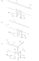
- the separator serving as the embedded panel assembly site side connection member may be a single separator having screw structures at both ends, a composite separator as shown in FIG. 4 (a), or a composite separator as shown in FIG. 4 (b). It may be a composite separator.
- the composite separator shown in FIG. 4A has a separator 41 having a positive screw structure at both ends and a reverse screw structure at both ends, or a positive screw structure at the left end in the drawing and a reverse screw structure at the right end in the drawing.
- a separator 42 having a screw structure portion and a connecting member 43 having screw hole portions into which these can be screwed at least at both ends are provided.
- each of the connecting members 43, 47, 48 is, for example, a so-called turnbuckle or joint nut.
- the above-mentioned various separators can be properly used depending on the mounting location or mounting height of the embedded panel 10 of the mold unit X.
- the fixture 30 of the formwork unit X may include a nut connector 30C as shown in FIG. 5A or a nut connector 30D as shown in FIG. 5B instead of the nut portion 30B.
- the nut connector 30C has a configuration in which two nut portions 34 and 35 are connected via a universal joint.
- the nut portion 34 has a screw hole 32 into which the above-described bolt 20 can be screwed.
- the nut part 35 has a screw hole part 32 'into which a screw structure part at the end of a so-called separator, which is a connection member on the side of the embedded panel assembling point, can be screwed.
- the nut connector 30D includes two nut portions 36 and 37 and a bolt portion 38.
- the nut portion 37 and the bolt portion 38 are connected via a universal joint.
- the nut portion 36 has a screw hole 32 into which the above-described bolt 20 can be screwed.
- the nut part 37 has a screw hole part 32 'into which a screw structure part at the end of a so-called separator, which is a connection member on the side of the embedded panel assembly point, can be screwed.
- the formwork unit X may further include a connection tool 50A as shown in FIG.
- the connection tool 50A is for connecting two adjacent buried panels 10 assembled in the construction of the concrete structure in a manner that their surfaces 12 are flush with each other, and in the present embodiment, at least in the embodiment, A plate 51 and a predetermined number of fastening members 52 are provided (FIG. 6A exemplarily shows a connection tool 50A when four fastening members 52 are provided).
- the flat plate 51 is applied to, for example, the surface 12 (outer surface) side of the two adjacent buried panels 10.
- the fastening material 52 is, for example, a drill screw.
- the fastening material 52 is a drill screw
- the surface 12 of the buried panel 10 is opposed to the flat plate 51 and a through hole formed so as to penetrate the buried panel 10.
- the fastening of the flat plate 51 over two adjacent buried panels 10 is realized by the fastening material 52 inserted from the side.
- the flat plate 51 may be applied to the surface 11 (inner surface) of the two embedded panels 10 adjacent to each other, or the fastening member 52 may be a bolt.
- the fastening material 52 is a bolt
- the bolt (fastening material 52) inserted from the surface 12 side of the embedded panel 10 into a through hole formed so as to penetrate the flat plate 51 and each embedded panel 10.
- a nut fastened to the screw structure on the side of the surface 11 realizes fixing of the flat plate 51 over two adjacent buried panels 10.
- connection tool 50A The fact that the form unit X is provided with such a connection tool 50A is that the step structure portion of the concrete structure with the step formed by using the form unit X (for example, a concrete wall 70 or a concrete structure 80 described later). In this case, it is preferable to appropriately form a flat side wall surface over the plurality of embedded panels 10. Also, after forming the side wall surface using such a connecting tool 50A, the fastening material 52 and the flat plate 51 when the flat plate 51 is applied to the surface 12 side are removed from the side wall surface. By repairing at least the outer opening end of the relatively small buried panel through hole into which the fastening material 52 has been inserted with mortar, it is possible to secure a good appearance on the side wall surface.
- connection tool 50A The number of the fastening members 52 included in one set of the connection tool 50A is four in FIG. 6A, but may be two, three, or five or more. In addition, the number of the connection tools 50A used to connect a pair of adjacent two embedded panels 10 is one in FIG. 6A, but may be two or three or more.
- the form unit X may further include a connecting tool 50B as shown in FIG.
- the connecting tool 50B is for connecting two adjacent buried panels 10 assembled in the construction of the concrete structure in a manner that their surfaces 11 intersect, and in this embodiment, at least the bent plate 53 is used.
- a predetermined number of fastening members 54 FIG. 6 (b) exemplarily shows the connecting tool 50B when four fastening members 54 are provided.
- the fastening material 54 is, for example, a drill screw.
- the fastening material 54 is a drill screw
- the surface 12 of the buried panel 10 is opposed to the bent plate 53 and the through hole formed so as to penetrate each buried panel 10.
- the fastening material 54 inserted from the side realizes the fixing of the bent plate 53 over the two adjacent embedded panels 10.
- the bent plate 53 may be applied to the surface 11 (inner surface) of the two embedded panels 10 adjacent to each other, or the fastening member 54 may be a bolt.
- the fastening member 54 is a bolt
- the bolt the fastening member 54
- the fastening member 54 inserted from the surface 12 side of the embedded panel 10 into the bent plate 53 and the through hole formed so as to penetrate each embedded panel 10.
- the nut fastened to the screw structure on the side of the surface 11 realizes the fixing of the bent plate 53 over the two adjacent buried panels 10.
- connection tool 50B The number of the fastening members 54 included in one set of the connection tool 50B is four in FIG. 6B, but may be two, three, or five or more.
- the number of the connectors 50B used to connect a pair of adjacent two embedded panels 10 is one in FIG. 6B, but may be two or three or more.
- the two buried panels 10 shown in FIG. 6B are arranged to form the step portion of the concrete structure having the step portion including the protruding corner portion (the above-described arrangement provided with the adhesion improving surface).
- the arrangement of the two buried panels 10 depends on the step including the corner portion. This is an arrangement (an arrangement in which a stepped portion including an entry corner portion is formed on the side of the surface 11 on which the adhesion improving surface is provided) of the concrete structure having a portion.
- the formwork unit X may further include a height adjuster 60A as shown in FIGS. 7A and 7B.
- the height adjuster 60A is for adjusting the height position of the embedded panel 10 to be assembled when the concrete structure is constructed, and includes a receiving member 61 having a screw structure extending downward, and a screw structure extending upward. And a connecting member 63 having screw holes at least at both ends to which these screw structures can be screwed.
- the receiving member 61 has a groove for receiving an embedded panel that is wider than the thickness of the embedded panel 10.
- the receiving member 61 may not have a groove for receiving an embedded panel.
- the receiving member 61 may have a flat plate of various shapes as a buried panel contact portion.
- connection member 63 is, for example, a turnbuckle or a joint nut.
- the height adjuster 60A shown in FIG. 7 (b) receives two adjacent embedded panels 10 in a connected state and simultaneously performs the height adjusting function of these embedded panels 10.
- the fact that the form unit X is provided with such a height adjusting tool 60A means that when the concrete structure (for example, a concrete wall 70 or a concrete structure 80 described later) is constructed using the form unit X, the embedded panel 10 is used. It is preferable for accurate positioning with respect to the assembling height.
- FIGS. 7A and 7B exemplarily show a height adjuster 60A in a case where two sets of leg members 62 and connecting members 63 are provided. May be provided with the leg member 62 and the connecting member 63, or may be provided with three or more pairs of the leg member 62 and the connecting member 63.
- the leg member 62 has a support end surface suitable for contacting the existing flat floor surface and a screw hole portion opened on the side opposite to the end surface, and a double-cut bolt or One end of the bar screw may be screwed in and the other end may form the screw structure.
- the member having the support end surface and the screw hole for example, the fixing tool 30 described above with reference to FIG. After the double-sided bolt or the bar screw is screwed into the screw hole 32 of the nut 30B of the fixture 30 from the side opposite to the pedestal 30A, the end face 31 of the pedestal 30A comes into contact with the flat floor surface.
- the leg member 62 is configured by being installed as described above.
- Examples of the above-mentioned connecting metal fittings include, for example, a product name “Sepa Grip” sold by Okabe Co., Ltd., a product name “SKA UNIVA” and a product name “Domaster” sold by Kyoei Seisakusho Co., Ltd.
- a joint fitting for connecting to a round bar "and a" connecting fitting between a reinforcing bar and a separator described in JP-A-2003-013600.
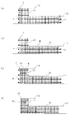
- FIG. 8 shows a concrete structure construction method according to an embodiment of the present invention.
- This method is a method for constructing a concrete wall 70 as shown in FIG. 8 (d) with a so-called rising step in a water return portion.
- the following formwork assembling step and the first concrete includes a setting step, a second concrete placing step, and a form removing step (in FIG. 8, each step is represented by a cross-sectional view).
- the concrete wall 70 to be formed has a step structure (a rising step in the water return portion) between the upper surface 71 and the upper surface 72 located thereabove.
- the embedded panel 10 having the bolt through holes 13.
- two adjacent buried panels 10 may be assembled in such a manner that the two embedded panels 10 are connected together with the above-described connector 50A and connector 50B.
- the embedded panel 10 may be assembled in such a manner that the height is adjusted together with the height adjuster 60A and the height adjuster 60B described above.
- the embedded panel 10 of the form unit X does not require the removal work after the construction as described above, and thus is suitable for assembling sufficiently firmly at the time of forming the form Y defining the concrete material filling section.
- Such a buried panel 10 is suitable for suppressing the occurrence of distortion at the time of placing concrete, and is therefore suitable for avoiding repair work required when the panel is distorted at the time of placing concrete.
- the formwork unit X including such a buried panel 10 is suitable for suppressing work, time, and cost required for constructing a concrete wall 70 which is a concrete structure with a step portion.
- the embedded panel 10 of the formwork unit X does not require the removal work after the construction as described above, the embedded panel 10 in the vertical direction is the same as or below the position where the upper surface 71 of the concrete wall 70 is to be formed. It is suitable for assembling the buried panel 10 so that the lower end is located.
- the formwork unit X having such a buried panel 10 is suitable for avoiding the formation of the surplus concrete portion described above with reference to the prior art, and works for scraping such a surplus portion and thereafter performing as needed. This is suitable for avoiding the repair work of the shaved portion, and is therefore suitable for suppressing the work, time and cost required for constructing the concrete wall 70 which is a concrete structure with a step.
- the form unit X described above is suitable for efficiently forming the concrete wall 70 that is a concrete structure having a step structure.
- FIG. 9 shows another concrete structure construction method according to an embodiment of the present invention.
- This method is a method for constructing a concrete structure 80 as shown in FIG. 9D with a so-called floor step at a wiring cable installation location or a bathroom construction location.
- the following formwork is used. It includes an assembling step, a first concrete placing step, a second concrete placing step, and a form removing step (in FIG. 9, each step is represented by a sectional view).
- the concrete structure 80 to be formed has a step structure (floor step) between the upper surface 81 and the upper surface 82 located above the upper surface 81.
- two adjacent buried panels 10 may be assembled in such a manner that the two embedded panels 10 are connected together with the above-described connector 50A and connector 50B. Further, the embedded panel 10 may be assembled in such a manner that the height is adjusted together with the height adjuster 60A and the height adjuster 60B described above.
- the buried panel 10 of the form unit X includes, as described above, the surface 11 having an adhesion improving surface suitable for joining with the concrete after hardening. Such a configuration is suitable for suppressing the peeling of the buried panel 10 from the cast concrete.
- the above-described form unit X is suitable for efficiently forming the concrete structure 80 having the step structure.
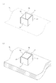
- the concrete structure to be formed includes a convex structure as the step structure, in the formwork assembling step of the concrete structure construction method shown in FIGS. 8 and 9, a part or a plurality of side walls of the convex structure is formed.
- One or two or more buried panels 10 to make up the whole are assembled at the protruding structure portion.
- FIG. 11A exemplarily shows a state in which four buried panels 10 for forming all the side walls forming the entire circumference of the convex structure portion are assembled at the convex structure portion forming portion.
- 11 (a) shows only one set of buried panels 10 in the formwork). As shown in FIG.
Landscapes
- Engineering & Computer Science (AREA)
- Architecture (AREA)
- Civil Engineering (AREA)
- Structural Engineering (AREA)
- Mechanical Engineering (AREA)
- Physics & Mathematics (AREA)
- Electromagnetism (AREA)
- Forms Removed On Construction Sites Or Auxiliary Members Thereof (AREA)
Abstract
段差構造を伴うコンクリート構造物を効率よく形成するのに適した型枠ユニットと施工方法を提供する。 本発明の型枠ユニットXは、埋設パネル10、ボルト20、および固定具30を備える。埋設パネル10は、例えば、接着改良面を含む面11とその反対側の面12を有し、且つボルト貫通孔13を有する。固定具30は、埋設パネル当接用の端面31と、端面31側からボルトが螺合可能なネジ孔部32とを有し、組付け箇所側連結部材に連結可能に構成されている。本発明の施工方法は、第1上面とこれより上位の第2上面との段差構造を含むコンクリート構造物を形成する方法であり、型枠ユニットXの埋設パネル10を含む必要数のパネルを組み付けてコンクリート原料充填区画を形成する工程と、区画内に第1上面形成高さまでコンクリート原料を供給する工程と、区画内に更に第2上面形成高さまでコンクリート原料を供給する工程を含む。
Description
本発明は、段差部を伴うコンクリート構造物を形成するのに使用される型枠ユニットおよびコンクリート構造物施工方法に関する。
コンクリート打設によるコンクリート構造物の施工過程では、コンクリート原料の充填範囲を区画するための型枠が、施工後にはコンクリート構造物から取り外される複数枚のパネルの組み付けによって形成されることが多い。このようなコンクリート打設用の型枠に関する技術については、例えば下記の特許文献1~3に記載されている。
形成目的物であるコンクリート構造物が、一の上向面(第1上向面)とこれより上位にある別の上向面(第2上向面)との段差構造を伴う場合、そのコンクリート構造物の施工過程で組まれる型枠をなす必要数のパネルには、当該段差構造における二つの上向面の間の側壁面を規定するためのパネルが含まれる。この側壁面規定用パネルについてコンクリート構造物施工後の取外し作業を適切に行うためには、従来、段差部付きコンクリート構造物の第1上向面が形成される高さ位置よりも側壁面規定用パネルの下端が上位に位置する態様で、当該パネルの組み付けが行われている(即ち、形成予定の第1上向面の高さ位置と側壁面規定用パネル下端との間に所定の間隔を伴う態様で、当該パネルの組み付けが行われている)。
しかしながら、このような態様で側壁面規定用パネルが組み付けられた状態でコンクリート打設が行われると、段差部付きコンクリート構造物の第1上向面が本来的に形成されるべき高さ位置と側壁面規定用パネル下端との間からの硬化前コンクリートの部分的漏出、即ち はみ出しが、生じる。そして、第1上向面と側壁面との境界では、当該はみ出しコンクリートが硬化して、本来的な入隅形状との比較において余剰な傾斜部など余剰部分が形成されることとなる(第1上向面と側壁面との境界には適切な入隅形状が形成されない)。第1上向面と側壁面とのこのような境界において適切な入隅形状を形成するためには、当該余剰部分を削り取る作業(はつり作業)を行う必要があり、また、その削り取り箇所の補修作業が必要となる場合もある。そのような作業が必要であることは、段差部付きコンクリート構造物の施工に要する作業・時間・コストの増大を招いてしまい、好ましくない。
また、段差部付きコンクリート構造物施工後の側壁面規定用パネルの取外し作業の効率化の観点から、従来、当該パネルの組み付けとして、簡易な手段による仮止めがなされる場合がある。その場合、側壁面規定用パネルを含む型枠による区画内に供給されて流動するコンクリート原料の自重や衝撃荷重など荷重に起因して、当該パネルには歪みが生じやすい。組み付けられた側壁面規定用パネルが歪むと、形成予定位置から位置ずれした側壁面が形成されてしまう。位置ずれを伴う側壁面については補修する必要があり、そのような補修が必要であることは、段差部付きコンクリート構造物の施工に要する作業・時間・コストの増大を招いてしまい、好ましくない。
本発明は、このような事情のもとで考え出されたものであり、その目的は、段差構造を伴うコンクリート構造物を効率よく形成するのに適した型枠ユニットおよび施工方法を提供することにある。
本発明の第1の側面によると、コンクリート段差部用型枠ユニットが提供される。このコンクリート段差部用型枠ユニットは、少なくとも一枚の埋設パネルと、少なくとも一つのボルトと、少なくとも一つの固定具とを備える。このような型枠ユニットは、いわゆる水返し部における立ち上がり段差を伴うコンクリート壁や、所定の段差構造を伴うコンクリート床など、段差部付きコンクリート構造物の施工のための型枠をなすために使用できるものである。
埋設パネルは、接着改良面を含む第1面およびこれとは反対の第2面を有し、且つ、当該第1および第2面間を貫通するボルト貫通孔を有する。或いは、埋設パネルは、接着改良面を含む第1面およびこれとは反対の第2面を有し、且つ、当該第1および第2面間を貫通するボルト貫通孔を形成可能であって当該ボルト貫通孔が未だ形成されていないものである。この場合、当該埋設パネルは、好ましくは、ボルト貫通孔形成予定箇所を示す印を第1面上および/または第2面上に有する。このような埋設パネルの接着改良面は、例えば硬化後コンクリートとの接合に適した面であって、モルタル硬化物層表面、凹凸成形面、または機械的粗化面である。
固定具は、埋設パネル当接用の端面、および、当該端面側からボルトが螺合可能なネジ孔部を有し、且つ、組付け箇所側連結部材に連結可能に構成されている。
以上の構成を有する本コンクリート段差部用型枠ユニットを例えば以下のように使用して、段差部付きコンクリート構造物を施工することができる。
まず、コンクリート構造物形成箇所において複数のパネルについて組み付けを行い、コンクリート原料が充填されることとなる区画を規定する型枠を形成する。形成目的物であるコンクリート構造物は、第1上面とこれより上位にある第2上面との段差構造を含む。組み付けられる複数のパネルには、そのような段差構造における第1上面および第2上面の間の側壁面をなすこととなる、上述のコンクリート段差部用型枠ユニットにおける少なくとも一枚の埋設パネルが、含まれる。この埋設パネルは、組付け作業までには必要数のボルト貫通孔が穿設された状態にある。
型枠の形成において、本コンクリート段差部用型枠ユニットの埋設パネルは、接着改良面を含む第1面がコンクリート原料充填区画内に臨む内面をなすように組み付けられる。本コンクリート段差部用型枠ユニットにおける固定具は、その埋設パネル当接用端面が埋設パネルの内面にあてがわれた状態において、当該固定具のネジ孔部と埋設パネルのボルト貫通孔とが連通可能な位置にある。本コンクリート段差部用型枠ユニットにおける上記ボルトは、埋設パネルにおける内面とは反対の外面からそのボルト貫通孔に挿通されたうえで、内面側にある固定具のネジ孔部に螺合している。この固定具は、組付け箇所側連結部材に連結されている。また、固定具の上述の埋設パネル当接用端面が広いほど、組付け状態にある埋設パネルにおいて意図しない傾きや歪みは抑えられる傾向にあり、好ましい。本コンクリート段差部用型枠ユニットが備える各要素の以上のような複合的な連携により、当該型枠ユニットの埋設パネルは組み付けられる。
段差部付きコンクリート構造物の施工においては、次に、型枠によって形成されたコンクリート原料充填区画において、上述の第1上面が形成されることとなる高さに対応する第1高さ位置までコンクリート原料を供給する。この後、供給されたコンクリート原料に対する締固めや、コテ等よる第1上面の表面仕上げを必要に応じて行ったうえで、養生を経て当該コンクリート原料を硬化させる。
次に、当該コンクリート原料充填区画において、上述の第2上面が形成される高さに対応する第2高さ位置まで更にコンクリート原料を供給する。この後、供給されたコンクリート原料に対する締固めや、コテ等よる第2上面の表面仕上げを必要に応じて行ったうえで、養生を経て当該コンクリート原料を硬化させる。これにより、本コンクリート段差部用型枠ユニットの埋設パネルは、コンクリート構造物と一体化し、その段差構造部分において第1上面と第2上面との間の側壁面をなすこととなる。
その後、本コンクリート段差部用型枠ユニットの埋設パネルをコンクリート構造物側に残しつつ、使用した型枠を必要に応じて解体する。
段差部付きコンクリート構造物の施工において本コンクリート段差部用型枠ユニットを使用する場合、上述のように、その埋設パネルは、形成される段差部付きコンクリート構造物と一体化してその段差部における第1上面と第2上面との間の側壁面をなす。本コンクリート段差部用型枠ユニットの埋設パネルは、施工後の取り外し作業を要しない。このような埋設パネルを備える本コンクリート段差部用型枠ユニットは、段差部付きコンクリート構造物の施工に要する作業・時間・コストを抑制するのに適する。
また、本コンクリート段差部用型枠ユニットの埋設パネルは、上述のように施工後の取り外し作業を要しないため、コンクリート原料充填区画を規定する型枠の形成時に充分強固に組み付けるのに適する。このような埋設パネルは、コンクリート打設時の歪みの発生を抑制するのに適し、従って、従来式のコンクリート構造物施工方法においてパネルが歪んだ場合に求められる上述の補修作業を回避するのに適する。このような埋設パネルを備える本コンクリート段差部用型枠ユニットは、段差部付きコンクリート構造物の施工に要する作業・時間・コストを抑制するのに適する。
加えて、本コンクリート段差部用型枠ユニットの埋設パネルは、上述のように施工後の取り外し作業を要しないため、鉛直方向においてコンクリート構造物の第1上面形成予定位置と同じか或いはそれより下方に埋設パネル下端が位置するように、当該埋設パネルを組み付けるのに適する。このような埋設パネルを備える本コンクリート段差部用型枠ユニットは、従来技術に関して上述したコンクリート余剰部分(第1上向面と側壁面との境界にてコンクリートが硬化して形成される余剰部分)が形成されるのを回避するのに適し、そのような余剰部分を削り取る作業やその後に必要に応じて行われる削り取り箇所補修作業を回避するのに適し、従って、段差部付きコンクリート構造物の施工に要する作業・時間・コストを抑制するのに適する。
更に加えて、本コンクリート段差部用型枠ユニットの埋設パネルは、上述のように、接着改良面を第1面に含む。このような構成は、本コンクリート段差部用型枠ユニットを使用して行うコンクリート構造物の施工において、打設コンクリートからの埋設パネル(接着改良面を含む第1面は内面)の剥離を抑制するのに適する。
以上のように、本発明の第1の側面に係るコンクリート段差部用型枠ユニットは、段差構造を伴うコンクリート構造物を効率よく形成するのに適する。
本コンクリート段差部用型枠ユニットにおける固定具のネジ孔部は、好ましくは、埋設パネル当接用の端面の側とは反対の側から組付け箇所側連結部材である例えばセパレータないしその端部が螺合可能に構成されている。このような構成は、埋設パネルについて強固な組み付けを実現するうえで好ましい。
本コンクリート段差部用型枠ユニットにおける固定具は、好ましくは、ネジ孔部を有するナット部と、埋設パネル当接用の端面を有し且つ当該端面とは反対の側にて開口してナット部が嵌合可能な穴部を有する台座部とを備える。このような構成は、構成材料が互いに異なるナット部および台座部を備える固定具を実現するのに適する。すなわち、埋設パネルの強固な組付けに寄与するネジ孔部に求められる特性を踏まえて構成材料が選択されたナット部と、埋設パネルの傾きや歪みの抑制機能を担う埋設パネル当接用端面に求められる特性を踏まえて構成材料が選択された台座部と、を備える複合的な構成の固定具を、実現するのに適するのである。一方、コンクリート段差部用型枠ユニットの部品点数の削減などの観点からは、本コンクリート段差部用型枠ユニットの固定具は、以上のようなナット部と台座部とが一体となった構成を有してもよい。
本コンクリート段差部用型枠ユニットの埋設パネルにおける第2面は、接着改良面を含んでもよい。このような構成、即ち、埋設パネルの両面が接着改良面を含むという構成は、本コンクリート段差部用型枠ユニットを使用して行うコンクリート構造物の施工において、打設コンクリートからの埋設パネルの剥離を抑制するのに適するとともに、当該施工後に埋設パネルの第2面に対してタイル貼り作業を実施するのにも適する。
本コンクリート段差部用型枠ユニットは、好ましくは、隣接する二枚の埋設パネルをそれらの第2面が面一となる態様で連ねて接続するための接続具を更に備える。このような構成は、本コンクリート段差部用型枠ユニットを使用して形成されるコンクリート構造物の上述の段差構造部分において、複数の埋設パネルにわたる広い平坦な側壁面を適切に形成するうえで好ましい。
本コンクリート段差部用型枠ユニットは、好ましくは、隣接する二枚の埋設パネルをそれらの第1面が交差する態様で連ねて接続するための接続具を更に備える。このような構成は、本コンクリート段差部用型枠ユニットを使用して形成されるコンクリート構造物の上述の段差構造部分において、横方向に連なって直角など所定角度をなす隣接平面を含む側壁面を適切に形成するうえで好ましい。
本コンクリート段差部用型枠ユニットは、埋設パネルの高さ位置を調整するための高さ調整具を更に備える。このような構成は、本コンクリート段差部用型枠ユニットを使用して行うコンクリート構造物の施工にあたり、埋設パネルの組付け高さについて正確に位置決めするうえで好ましい。
本発明の第2の側面によると、コンクリート構造物施工方法が提供される。この施工方法は、本発明の第1の側面に係る上述のコンクリート段差部用型枠ユニットを使用して、第1上面とこれより上位の第2上面との段差構造を含むコンクリート構造物を形成するための方法であって、次のような第1工程、第2工程、および第3工程を少なくとも含む。第1工程では、複数のパネルについて組み付けを行い、コンクリート原料が充填されることとなる区画を規定する型枠を形成する。組み付けられる複数のパネルには、上記段差構造における第1上面および第2上面の間の側壁面をなすこととなる、コンクリート段差部用型枠ユニットにおける少なくとも一枚の埋設パネルが、含まれる。第2工程では、コンクリート原料充填区画において、第1上面形成高さに対応する第1高さ位置までコンクリート原料を供給する。第3工程では、コンクリート原料充填区画において、第2上面形成高さに対応する第2高さ位置まで更にコンクリート原料を供給する。本施工方法では、組み付けられた状態にある埋設パネル(即ち、型枠における埋設パネル)の下端位置は、好ましくは、鉛直方向において上記第1高さ位置と同じか或いは当該第1高さ位置より下方である。
本コンクリート構造物施工方法では、上述のように、段差部付きコンクリート構造物のための型枠を形成するにあたり、本発明の第1の側面に係るコンクリート段差部用型枠ユニットが使用される。このような施工方法によると、本発明の第1の側面に係るコンクリート段差部用型枠ユニットに関して上述したのと同様の技術的効果が奏される。すなわち、本発明の第2の側面に係る本施工方法は、段差構造を伴うコンクリート構造物を効率よく形成するのに適する。
本コンクリート構造物施工方法では、コンクリート構造物は、第1上面とこれより上位の第2上面との間で互いに反対の側を向く一対の側壁面を有する凸条構造部を含んでもよい。この場合、上記第1工程で形成される型枠には、凸条構造部の一対の側壁面をなすための、離隔して組み付けられた少なくとも一対の埋設パネルが、含まれる。このような施工方法によっても、本発明の第1の側面に係るコンクリート段差部用型枠ユニットに関して上述したのと同様の技術的効果が奏される。すなわち、このような施工方法は、段差構造として凸条構造部を伴うコンクリート構造物を効率よく形成するのに適する。
本コンクリート構造物施工方法では、コンクリート構造物は、第1上面とこれより上位の第2上面との間において全周をなす複数の側壁面を有する凸構造部を含んでもよい。この場合、上記第1工程で形成される型枠には、凸構造部の複数の側壁面の一部または全部をなすための一枚または二枚以上の埋設パネルが含まれる。このような施工方法によっても、本発明の第1の側面に係るコンクリート段差部用型枠ユニットに関して上述したのと同様の技術的効果が奏される。すなわち、このような施工方法は、段差構造として凸構造部を伴うコンクリート構造物を効率よく形成するのに適する。
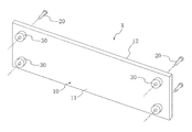
図1から図3は、本発明の一の実施形態に係るコンクリート段差部用型枠ユニットである型枠ユニットXを表す。型枠ユニットXは、少なくとも一枚の埋設パネル10を備え、且つ、埋設パネル10ごとに少なくとも一組のボルト20および固定具30を備える。このような型枠ユニットXは、いわゆる水返し部における立ち上がり段差を伴うコンクリート壁や、所定の段差構造を伴うコンクリート床など、段差部付きコンクリート構造物の施工のための型枠をなすために使用できるものである。
埋設パネル10は、面11およびこれとは反対の面12を有する矩形状の板材であって、本実施形態では、平板状の繊維強化セメント板である。埋設パネル10において、その長手方向の寸法は例えば30~242cmであり、短手方向の寸法は例えば2~242cmである。また、埋設パネル10は、図3に示すように、面11,12間を貫通するボルト貫通孔13を有する。或いは、埋設パネル10は、面11,12間を貫通するボルト貫通孔13を形成可能なものであってボルト貫通孔13が未だ形成されてないものであってもよい。この場合、埋設パネル10は、図2に示すように、ボルト貫通孔形成予定箇所を示す印21を面11上および/または面12上に有するのが、好ましい。
埋設パネル10をなすための平板状の繊維強化セメント板としては、例えば、スレートボード、珪酸カルシウム板、およびスラグ石膏板が挙げられる。スレートボードは、主原料として、例えば、セメント、繊維(但し石綿を除く)、および混和材を含む。珪酸カルシウム板は、主原料として、例えば、石灰質原料、珪酸質原料、繊維(但し石綿を除く)、および混和材を含む。スラグ石膏板は、主原料として、例えば、スラグ、石膏、繊維(但し石綿を除く)、および混和材を含む。これら繊維強化セメント板については、JIS A 5430に規格が定められている。耐水性の観点からは、埋設パネル10をなすための繊維強化セメント板としては、スレートボードおよび珪酸カルシウム板が好ましい。また、スレートボードの市販品としては、例えば、株式会社エーアンドエーマテリアル製の「セルフレックス」が挙げられる。珪酸カルシウム板の市販品としては、例えば、株式会社エーアンドエーマテリアル製の「ハイラックM」が挙げられる。スラグ石膏板の市販品としては、例えば、吉野石膏株式会社製の「タイガーボード」が挙げられる。
埋設パネル10の厚さは、好ましくは3mm以上、より好ましくは5mm以上、更に好ましくは7mm以上である。このような構成は、埋設パネル10の強度の確保の観点から好ましく、ひいては、埋設パネル10の運搬時および組付け作業時、並びにコンクリート打設の際の、埋設パネル10の破損や撓みを抑制するうえで好ましい。また、埋設パネル10の厚さは、好ましくは30mm以下、より好ましくは20mm以下、更に好ましくは10mm以下である。このような構成は、埋設パネル10の軽量化の観点から好ましく、ひいては、埋設パネル10の製造コストおよび運搬コストの抑制、並びに、埋設パネル10の組付け作業のしやすさの観点から好ましい。
埋設パネル10の面11には、その一部または全体にわたって接着改良面が設けられている。埋設パネル10の面12には、その一部または全体にわたり、接着改良面が設けられてもよいし、化粧面が設けられてもよい。
埋設パネル10における接着改良面は、例えば、モルタル硬化物層表面、凹凸成形面、機械的粗化面、または、これらの組み合わせである。埋設パネル10の量産化や経済性の観点からは、埋設パネル10の接着改良面としてはモルタル硬化物層表面が好ましい。
埋設パネル10におけるモルタル硬化物層表面は、上述の繊維強化セメント板における接着改良面形成予定箇所にモルタルを塗布した後に硬化させることによって形成することができる。当該モルタルとしては、例えば、ポリマーセメントモルタル、エポキシ樹脂モルタル、およびカチオン系モルタルが挙げられる。
ポリマーセメントモルタルは、例えば、セメントと、細骨材と、水と、ポリマーディスパージョンまたは再乳化形粉末樹脂との混合物であるモルタルである。ポリマーディスパージョンとしては、エチレン酢酸ビニル樹脂(EVA)およびアクリル樹脂があげられる。ポリマーディスパージョンとして用いることが可能なエチレン酢酸ビニル樹脂の市販品としては、例えば、ダイセルファインケム株式会社製の「セルマイティ10」が挙げられる。ポリマーディスパージョンとして用いることが可能なアクリル樹脂の市販品としては、例えば、旭化成株式会社製の「スーパーペトロック400」が挙げられる。
カチオン系モルタルは、例えば、セメントと、細骨材と、水と、カチオン系ポリマーディスパージョンまたはカチオン系再乳化形粉末樹脂との混合物であるモルタルである。カチオン系ポリマーディスパージョンとしては、カチオン系スチレンブタジエンゴムおよびカチオン系アクリル樹脂が挙げられる。カチオン系ポリマーディスパージョンとして用いることが可能なカチオン系スチレンブタジエンゴムの市販品としては、ダイセルファインケム株式会社製の「セルタル」が挙げられる。カチオン系ポリマーディスパージョンとして用いることが可能なカチオン系アクリル樹脂の市販品としては、ダイセルファインケム株式会社製の「セルカチオン」が挙げられる。
エポキシ樹脂モルタルは、例えば、エポキシ樹脂と細骨材との混合物であるモルタルある。エポキシ樹脂モルタルの市販品としては、例えばコニシ株式会社製の「Kモルタル」が挙げられる。
上述のモルタル中の細骨材としては、例えば、珪砂、川砂、黒曜石パーライト、真珠岩パーライト、炭酸カルシウム粉が挙げられる。モルタル中には、一種類の細骨材が含まれてもよいし、二種類以上の細骨材が含まれてもよい。
埋設パネル10における接着改良面がモルタル硬化物層表面である場合、そのモルタル硬化物層の厚さは、コンクリート原料に対する高い接着強度を確保するという観点からは、好ましくは0.5mm以上、より好ましくは1mm以上、更に好ましくは1.5mm以上である。また、埋設パネル10に関する軽量化および作業性の改善の観点や、埋設パネル10の製造コストおよび運搬コストの抑制の観点からは、当該モルタル硬化物層の厚さは、好ましくは10mm以下、より好ましくは5mm以下、更に好ましくは3mm以下である。
繊維強化セメント板にポリマーセメントモルタルやカチオン系モルタルが塗布されると、塗布されたモルタル中の水分の多くが繊維強化セメント板に吸収され、当該モルタルがいわゆるドライアウトの状態に至りやすい。ドライアウト状態にあるモルタルでは、水和反応が阻害されて硬化不良や接着不良を生じることがある。このようなドライアウトを避けるためには、モルタル塗布前の繊維強化セメント板について、いわゆる吸水調整を行うのが好ましい。吸水調整手段としては、例えば、繊維強化セメント板に対する水の散布、および、繊維強化セメント板に対する吸水調整剤の塗布が、挙げられる。その吸水調整剤としては、例えば、合成樹脂のエマルジョンまたはポリマーディスパージョンを主成分とする、いわゆるセメントモルタル塗り用の吸水調整剤が挙げられる。そのような吸水調整剤中の合成樹脂としては、例えば、アクリル系樹脂、酢酸ビニル系樹脂、エチレン酢酸ビニル系樹脂、および合成ゴムが挙げられる。セメントモルタル塗り用の吸水調整剤の市販品としては、例えば、ダイセルファインケム株式会社製の「セルマイティ10」「セルタイト10」「セルロックJ」「セルプライマーJ」(いずれもエチレン酢酸ビニル系樹脂を含有する)、および、昭和電工建材株式会社製の「マルチプライマー」「ペルタスAC-300」(いずれもアクリル系樹脂を含有する)が、挙げられる。
埋設パネル10における接着改良面としての上述の凹凸成形面は、例えば、埋設パネル10をなすための繊維強化セメント板の作製過程で、接着改良面形成予定箇所に接する表面に所定の凹凸形状を有する型板など型部材を使用して繊維強化セメント板をプレス成形または押出成形することにより、形成することができる。
埋設パネル10における接着改良面としての上述の機械的粗化面は、例えば、埋設パネル10をなすための繊維強化セメント板の接着改良面形成予定箇所に対してサンディングまたはチッピングなど機械的な粗面化処理を行って当該箇所を目粗しすることにより、形成することができる。
埋設パネル10の面12の一部または全体にわたり化粧面が設けられている場合、型枠ユニットXを使用してのコンクリート構造体の施工の後、埋設パネル10の外面に新たにモルタル化粧や塗装を施さなくてもよく、作業効率の観点から好ましい。埋設パネル10の面12の一部または全体にわたり化粧面が設けられている場合のその化粧面は、例えば、平滑平面成形面、塗料硬化膜表面、または化粧シート貼付面である。
埋設パネル10における平滑平面成形面は、例えば、埋設パネル10をなすための繊維強化セメント板の作製過程で、化粧面形成予定箇所に接する表面が平滑平面である型板など型部材を使用して繊維強化セメント板をプレス成形または押出成形することにより、形成することができる。このような平滑平面成形面を有するパネル(繊維強化セメント板)として、せんい強化セメント板協会のスレートボードの一種である「フレキシブル板(化粧板仕上げタイプ)」が知られている。
埋設パネル10における塗料硬化膜表面は、埋設パネル10をなすための繊維強化セメント板の化粧面形成予定箇所に塗料を塗布した後に硬化させることによって形成することができる。使用可能な塗料としては、例えば、有機系塗料、無機系塗料、および有機・無機複合系塗料が挙げられる。形成される塗料硬化膜表面の耐久性の観点からは、無機系塗料や有機・無機複合形塗料が好ましい。有機系塗料としては、例えば、アクリル樹脂塗料、エポキシ系塗料、ウレタン樹脂塗料、フッ素樹脂塗料、ポリエステル塗料、およびビニルオルガノゾル塗料が挙げられる。無機系塗料としては、例えば、アルキルシリケート系塗料、光触媒酸化チタン含有無機塗料、シリカゾル系塗料、アルカリ金属塩系塗料、金属アルコキシド系塗料、セメントリシン系塗料、およびセメントスタッコ系塗料が挙げられる。有機・無機複合系塗料としては、例えば、シロキサン結合を含有する有機・無機複合系塗料、金属アルコキシド系塗料、セラミックス系塗料、および光触媒酸化チタン含有有機・無機複合系塗料が挙げられる。これら塗料は、充填剤、増粘剤、レベリング剤、消泡剤、安定剤などその他の添加剤を顔料に加えて含有していてもよい。
埋設パネル10における化粧シート貼付面を形成するための化粧シートとしては、例えば、塩化ビニル化粧シート、熱可塑性樹脂化粧シート、熱硬化性樹脂化粧シート、葉化粧シート、およびいわゆるPタイルが挙げられる。塩化ビニル化粧シートは、例えば、顔料を混練した不透明の塩化ビニルシートに模様の印刷を施し、その印刷面上に透明な塩化ビニルフィルムを加熱接着し、当該印刷面側を必要に応じてエンボス加工して作製することができる。そのエンボス加工は、例えば、凹凸表面を有するロールでの加圧によって行うことができる。熱可塑性樹脂化粧シートは、例えば、シート構成樹脂として塩化ビニル樹脂の代りに各種可塑性樹脂を用いること以外は塩化ビニル化粧シート作製方法と同様にして、作製することができる。熱硬化性樹脂化粧シートは、坪量55~200g/m2の化粧紙にメラミン樹脂、ジアリルフタレート樹脂、ポリエステル樹脂などの熱硬化性樹脂を含浸したものを、同様の熱硬化性樹脂を含浸したクラフト紙など基材シートに重ね、得られる積層体について多段式ホットプレス機または連続成形プレス機を使用して熱圧プレス成形することによって、作製ことができる。薄葉化粧シートは、例えば、坪量30g/m2程度の薄葉紙に着色ベタ印刷を施し、そのベタ印刷面上に図柄を印刷し、当該印刷面に対してアミノアルキッド樹脂塗料またはポリウレタン樹脂塗料などによる塗装仕上げを施すことによって、作製することができる。埋設パネル10における化粧シート貼付面を形成するための化粧シートは、好ましくは、塩化ビニル化粧シートおよびPタイルである。埋設パネル10をなすための繊維強化セメント板に対する化粧シートの貼付方法としては、ウレタン樹脂や、ビニル樹脂、アクリル樹脂など接着性樹脂を介しての接着があげられる。
以上のような埋設パネル10としては、特開平8-312092号公報に記載のもの(但し、石綿は含有していないもの)、および、ダイセルファインケム株式会社製の「セル・ケコミパネル」が、特に好ましい。
型枠ユニットXのボルト20は、その延び方向において埋設パネル10の厚さより長い寸法を有し、且つ、所定のネジ山を有する。ボルト20は、公知のものから選択できる。例えば、六角ボルト、六角穴付ボルト、座金組み込み六角ボルト、アイボルト、蝶ボルト、ナベ子ねじ、皿子ねじ、トラス子ねじ、バインド子ねじ、および止めねじから選択されたものを、ボルト20として使用することができる。また、ボルト20として、型枠固定用として公知の各種フォームタイ(登録商標)(或いは、ホームタイ)のメスねじ部に棒ねじ(“寸切りねじ”や“全ねじ”と呼称されることもある)の一部をねじ込ませて残部を露出させたものを使用してもよい。そのフォームタイ(登録商標)(或いは、ホームタイ)としては、市販のものを使用することができる。市販のフォームタイ(登録商標)としては、例えば、ナット付タイプのフォームタイ(登録商標)(岡部株式会社から販売されている商品名「フォームタイ(登録商標)C型 C8-150」など)、くさびタイプのフォームタイ(登録商標)(コンドーテック株式会社から販売されている商品名「くさび式ホンタイ 2K-60 W5/16・60角パイプ用」など)、および、ねじタイプのフォームタイ(登録商標)(コンドーテック株式会社から販売されている商品名「RBねじホンタイ(3形リブ座ナット・SWセット)8-180」など)が挙げられる。
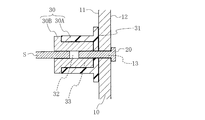
型枠ユニットXの固定具30は、図3に示すように、埋設パネル当接用の端面31と端面31側からボルト20が螺合可能なネジ孔部32とを有し、且つ、組付け箇所側連結部材に連結可能に構成されている。
本実施形態の固定具30においては、埋設パネル組付け箇所側連結部材であるいわゆるセパレータの端部のネジ構造部が固定具30の端面31側とは反対の側からネジ孔部32に螺合可能に構成されている。このような構成は、後述のコンクリート構造物施工過程において、埋設パネル10について強固な組み付けを実現するうえで好ましい。
本実施形態の固定具30は、具体的には、埋設パネル当接用の端面31および穴部33を有する台座部30Aと、ネジ孔部32を有するナット部30Bとを備える。台座部30Aの穴部33は、台座部30Aの端面31とは反対の側にて開口し、この穴部33にはナット部30Bが嵌合可能である。このような構成によると、構成材料が互いに異なる台座部30Aおよびナット部30Bを備える固定具30を実現することが可能である。すなわち、埋設パネル10の傾きや歪みの抑制機能を担う埋設パネル当接用の端面31に求められる特性を踏まえて構成材料が選択された台座部30Aと、埋設パネル10の強固な組付けに寄与するネジ孔部32に求められる特性を踏まえて構成材料が選択されたナット部30Bと、を備える複合的な構成の固定具30を、実現することが可能なのである。このような固定具30としては、例えば、コンドーテック株式会社から販売されている商品名「断熱パット」や、三協テック株式会社から販売されている商品名「断熱コン(KPコン)」など、市販品を使用することができる。一方、型枠ユニットXの部品点数の削減などの観点からは、固定具30は、上述のような台座部とナット部とが一体となった構成を有してもよい。
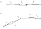
埋設パネル組付け箇所側連結部材であるセパレータは、両端にネジ構造部を有する一本のセパレータであってもよいし、図4(a)に示すような複合セパレータや図4(b)に示す複合セパレータであってもよい。図4(a)に示す複合セパレータは、両端に正ネジ構造部を有するセパレータ41と、両端に逆ネジ構造部を有するか或いは図中左端に正ネジ構造部を有し且つ図中右端に逆ネジ構造部を有するセパレータ42と、これらが螺合可能なネジ孔部を少なくとも両端に有する連結部材43とを備える。図4(b)に示す複合セパレータは、両端に正ネジ構造部を有するセパレータ44,45と、両端に逆ネジ構造部を有する屈曲型のセパレータ46と、セパレータ44,46が螺合可能なネジ孔部を少なくとも両端に有する連結部材47と、セパレータ45,46が螺合可能なネジ孔部を少なくとも両端に有する連結部材48とを備える。連結部材43,47,48は、それぞれ、例えば、いわゆるターンバックルまたはジョイントナットである。型枠ユニットXの埋設パネル10の組付け箇所ないし組付け高さに応じて、例えば以上の各種セパレータを使い分けることができる。
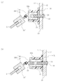
型枠ユニットXの固定具30は、図5(a)に示すようなナット連結体30Cや図5(b)に示すようなナット連結体30Dを、上述のナット部30Bの代わりに備えてもよい。ナット連結体30Cは、二つのナット部34,35が自在継ぎ手を介して連結された構成を有するものである。ナット部34は、上述のボルト20が螺合可能なネジ孔部32を有する。ナット部35は、埋設パネル組付け箇所側連結部材であるいわゆるセパレータの端部のネジ構造部が螺合可能なネジ孔部32'を有する。ナット連結体30Dは、二つのナット部36,37とボルト部38とを備える。ナット部37とボルト部38は、自在継ぎ手を介して連結されている。ナット部36は、上述のボルト20が螺合可能なネジ孔部32を有する。ナット部37は、埋設パネル組付け箇所側連結部材であるいわゆるセパレータの端部のネジ構造部が螺合可能なネジ孔部32'を有する。
型枠ユニットXは、図6(a)に示すような接続具50Aを更に備えてもよい。接続具50Aは、コンクリート構造物の施工にあたって組み付けられる隣接する二枚の埋設パネル10をそれらの面12が面一となる態様で連ねて接続するためのものであって、本実施形態では少なくとも平プレート51および所定数の締結材52を備える(図6(a)は、四つの締結材52を備える場合の接続具50Aを例示的に表すものである)。隣接する二枚の埋設パネル10が接続具50Aによって接続された状態において、平プレート51は、隣接する二枚の埋設パネル10にわたり、それらの例えば面12(外面)側にあてがわれている。締結材52は例えばドリルねじであり、締結材52がドリルねじである場合には、平プレート51および各埋設パネル10を貫通するように穿設された貫通孔に対して埋設パネル10の面12側から挿入された締結材52により、隣接する二枚の埋設パネル10にわたる平プレート51の固定が実現される。このような接続具50Aにおいて、平プレート51は、隣接する二枚の埋設パネル10にわたってそれらの面11(内面)側にあてがわれてもよいし、締結材52はボルトであってもよい。締結材52がボルトである場合には、平プレート51および各埋設パネル10を貫通するように穿設された貫通孔に対して埋設パネル10の面12側から挿入された当該ボルト(締結材52)と、そのネジ構造部に面11側にて締結されるナットとにより、隣接する二枚の埋設パネル10にわたる平プレート51の固定が実現される。
型枠ユニットXがこのような接続具50Aを備えることは、型枠ユニットXを使用して形成される段差部付きコンクリート構造部(例えば後記のコンクリート壁70やコンクリート構造物80)の段差構造部分において、複数の埋設パネル10にわたる平坦な側壁面を適切に形成するうえで好ましい。また、このような接続具50Aを使用しつつ側壁面を形成した後、締結材52と、面12側に平プレート51があてがわれる場合には当該平プレート51とを、当該側壁面から取り外し、締結材52が挿入されていた比較的に小さな埋設パネル貫通孔の少なくとも外側開口端部にモルタルを充填する補修を行うことにより、当該側壁面において良好な美観を確保することができる。
一組の接続具50Aが備える締結材52の数は、図6(a)では4であるが、2、3または5以上であってもよい。また、一組の隣接する二枚の埋設パネル10を接続するために使用される接続具50Aの数は、図6(a)では1であるが、2または3以上であってもよい。
型枠ユニットXは、図6(b)に示すような接続具50Bを更に備えてもよい。接続具50Bは、コンクリート構造物の施工にあたって組み付けられる隣接する二枚の埋設パネル10をそれらの面11が交差する態様で連ねて接続するためのものであって、本実施形態では少なくとも屈曲プレート53および所定数の締結材54を備える(図6(b)は、四つの締結材54を備える場合の接続具50Bを例示的に表すものである)。隣接する二枚の埋設パネル10が接続具50Bによって接続された状態において、屈曲プレート53は、隣接する二枚の埋設パネル10にわたり、それらの例えば面12(外面)側にあてがわれている。締結材54は例えばドリルねじであり、締結材54がドリルねじである場合には、屈曲プレート53および各埋設パネル10を貫通するように穿設された貫通孔に対して埋設パネル10の面12側から挿入された締結材54により、隣接する二枚の埋設パネル10にわたる屈曲プレート53の固定が実現される。このような接続具50Bにおいて、屈曲プレート53は、隣接する二枚の埋設パネル10にわたってそれらの面11(内面)側にあてがわれてもよいし、締結材54はボルトであってもよい。締結材54がボルトである場合には、屈曲プレート53および各埋設パネル10を貫通するように穿設された貫通孔に対して埋設パネル10の面12側から挿入された当該ボルト(締結材54)と、そのネジ構造部に面11側にて締結されるナットとにより、隣接する二枚の埋設パネル10にわたる屈曲プレート53の固定が実現される。
型枠ユニットXがこのような接続具50Bを備えることは、型枠ユニットXを使用して形成される段差部付きコンクリート構造部(例えば後記のコンクリート壁70やコンクリート構造物80)の段差構造部分において、横方向に連なって直角など所定角度をなす隣接平面を含む側壁面を適切に形成するうえで好ましい。また、このような接続具50Bを使用しつつ側壁面を形成した後、締結材54と、面12側に屈曲プレート53があてがわれる場合には当該屈曲プレート53とを、当該側壁面から取り外し、締結材54が挿入されていた比較的に小さな埋設パネル貫通孔の少なくとも外側開口端部にモルタルを充填する補修を行うことにより、当該側壁面において良好な美観を確保することができる。
一組の接続具50Bが備える締結材54の数は、図6(b)では4であるが、2、3または5以上であってもよい。また、一組の隣接する二枚の埋設パネル10を接続するために使用される接続具50Bの数は、図6(b)では1であるが、2または3以上であってもよい。
また、図6(b)に示される二枚の埋設パネル10は、出隅部位を含む段差部を有するコンクリート構造物の当該段差部を形成するための配置(接着改良面が設けられている上述の面11の側に、出隅部位を含む段差部が形成される配置)をとる。これに対し、図6(b)に示される各埋設パネル10につきその表裏面(面11,12)を入れ変えた場合に当該二枚の埋設パネル10がとる配置は、入隅部位を含む段差部を有するコンクリート構造物の当該入隅部を形成するための配置(接着改良面が設けられている面11の側に、入隅部位を含む段差部が形成される配置)である。
型枠ユニットXは、図7(a)および図7(b)に示すような高さ調整具60Aを更に備えてもよい。高さ調整具60Aは、コンクリート構造物の施工にあたって組み付けられる埋設パネル10の高さ位置を調整するためのものであって、下方に延びるネジ構造部を伴う受け部材61と、上方に延びるネジ構造部を伴う脚部材62と、これらのネジ構造部が螺合可能なネジ孔部を少なくとも両端に有する連結部材63とを備える。受け部材61は、本実施形態では、埋設パネル10の厚さより幅の広い埋設パネル受容用の溝を有する。そのような構成に代えて、受け部材61は、埋設パネル受容用の溝を有さないものでもよい。例えば、受け部材61は、各種形状の平面プレートを埋設パネル当接部として有するものでもよい。その平面プレートは、埋設パネル10の面11または面12に当接して埋設パネル10の位置規定にも役立てられうる上方折り返し構造を有するものであってもよい。或いは、受け部材61は、埋設パネル支持用棒状部材を埋設パネル当接部として有するものでもよい。その棒状部材は、埋設パネル10の面11または面12に当接して埋設パネル10の位置規定にも役立てられうる上方折り返し構造を有するものであってもよいし、V字形状やU字形状を有するものであってもよい。受け部材61が上記溝を有さないこれら構成は、埋設パネル10の組付けにあたってその組付け箇所・配向の自由度を確保する観点から好ましい。一方、連結部材63は、例えば、ターンバックルまたはジョイントナットである。図7(b)に示す高さ調整具60Aは、隣接する二枚の埋設パネル10を連ねた状態で受けてこれら埋設パネル10の高さ調整機能を同時に担う。型枠ユニットXがこのような高さ調整具60Aを備えることは、型枠ユニットXを使用して行うコンクリート構造物(例えば後記のコンクリート壁70やコンクリート構造物80)の施工にあたり、埋設パネル10の組付け高さについて正確に位置決めするうえで好ましい。
図7(a)および図7(b)は、脚部材62および連結部材63を二組備える場合の高さ調整具60Aを例示的に表すものであって、高さ調整具60Aは、一組の脚部材62および連結部材63を備えるものであってもよいし、三組以上の脚部材62および連結部材63を備えるものであってもよい。
高さ調整具60Aにおいて、脚部材62は、上方に延びるネジ構造部を有していればよく、当該ネジ構造部の下方側は、高さ調整具60Aが埋設パネル10の高さ位置を調整する機能を発揮可能であれば、どのような構成のものでもよい。
例えば、脚部材62は、上記ネジ構造部を少なくとも一方端側に有する棒状部材であって、その他方端が既存の床面などに当接して高さ調整具60Aの一部をなす棒状部材であってもよい。そのような棒状部材としては、例えばセパレータが挙げられる。当該棒状部材の前記他方端(ネジ構造部とは反対側の端)は、既存の床面などに当接するのに適した所定の形状や構造を有していてもよい。
或いは、脚部材62は、既存の平面状床面に当接するのに好適な支持端面と当該端面とは反対の側にて開口するネジ孔部とを有する部材の当該ネジ孔部に両切りボルトや棒ねじの一方端部がねじ込まれ且つその他方端部が上記ネジ構造部をなすものでもよい。支持端面とネジ孔部とを有する前記部材としては、例えば、図3を参照して上述した固定具30が挙げられる。固定具30におけるナット部30Bのネジ孔部32に対して台座部30Aとは反対の側から両切りボルトや棒ねじがねじ込まれたうえで、台座部30Aの端面31が平面状床面に当接するように設置されることにより、脚部材62が構成される。
或いは、脚部材62は、セパレータの下端が既存のコンクリートに埋め込まれた構成を有するもの(いわゆるアンカーボルト)であってもよいし、セパレータの下端が鉄骨または配筋などの鉄部材に溶接固定された構成を有するものであってもよいし、セパレータと配筋とを連結するための連結金具を介してセパレータの下端が配筋に連結された構成を有するものであってもよい(いずれにおいても、セパレータの上端側は「上方に延びるネジ構造部」をなす)。前記の連結金具としては、例えば、岡部株式会社から販売されている商品名「セパグリップ」、共栄製作所株式会社から販売されている商品名「エスケーユニバ」および商品名「ドマスター」、日本仮設株式会社から販売されている商品名「テツカブト(ナット付)」、株式会社国元商会から販売されている商品名「KSガッツ」、特開2008-214911号公報に記載されている「セパレータと鉄筋または丸棒とを接続するためのジョイント金具」、並びに、特開2003-013600号公報に記載されている「鉄筋とセパレータとの連結金具」が挙げられる。
型枠ユニットXは、図7(c)に示すような高さ調整具60Bを更に備えてもよい。高さ調整具60Bは、コンクリート構造物の施工にあたって組み付けられる隣接する二枚の埋設パネル10をそれらの面11が直角など所定角度で交差する態様で連ねつつ当該埋設パネル10の高さ位置を調整するためのものであって、下方に延びるネジ構造部を伴う受け部材64と、上方に延びるネジ構造部を伴う脚部材65と、これらのネジ構造部が螺合可能なネジ孔部を少なくとも両端に有する連結部材66とを備える。受け部材64は、本実施形態では、埋設パネル10の厚さより幅の広い埋設パネル受容用の溝を有する。そのような構成に代えて、受け部材64は、埋設パネル受容用の溝を有さないものでもよい。例えば、受け部材64は、各種形状の平面プレートを埋設パネル当接部として有するものでもよい。その平面プレートは、埋設パネル10の面11または面12に当接して埋設パネル10の位置規定にも役立てられうる上方折り返し構造を有するものであってもよい。或いは、受け部材64は、埋設パネル支持用棒状部材を埋設パネル当接部として有するものでもよい。受け部材61が上記溝を有さないこれら構成は、埋設パネル10の組付けにあたってその組付け箇所・配向の自由度を確保する観点から好ましい。一方、連結部材66は、例えば、ターンバックルまたはジョイントナットである。型枠ユニットXがこのような高さ調整具60Bを備えることは、型枠ユニットXを使用して行うコンクリート構造物(例えば後記のコンクリート壁70やコンクリート構造物80)の施工にあたり、交差態様で隣接する二枚の埋設パネル10の組付け高さについて正確に位置決めするうえで好ましい。
図7(c)は、脚部材65および連結部材66を三組備える場合の高さ調整具60Bを例示的に表すものであって、高さ調整具60Bは、一組の脚部材65および連結部材66を備えるものであってもよいし、二組の脚部材65および連結部材66を備えるものであってもよいし、四組以上の脚部材65および連結部材66を備えるものであってもよい。また、高さ調整具60Bの脚部材65は、上方に延びるネジ構造部を有していればよく、当該ネジ構造部の下方側は、高さ調整具60Bが埋設パネル10の高さ位置を調整する機能を発揮可能であれば、どのような構成のものでもよい。高さ調整具60Bにおけるそのようなネジ構造部下方側の構成は、具体的には、高さ調整具60Aにおけるネジ構造部下方側の構成に関して上述したのと同様である。
図8は、本発明の一の実施形態に係るコンクリート構造物施工方法を表す。本方法は、いわゆる水返し部における立ち上がり段差を伴う図8(d)に示すようなコンクリート壁70の施工方法であり、本実施形態では、以下のような型枠組立て工程と、第1コンクリート打設工程と、第2コンクリート打設工程と、型枠取外し工程とを含む(図8では、各工程を断面図で表す)。形成目的物であるコンクリート壁70は、上面71とこれより上位にある上面72との段差構造(水返し部における立ち上がり段差)を伴うものである。
型枠組立て工程では、図8(a)に示すように型枠Yを形成する。具体的には、コンクリート壁70の形成箇所において、縦筋や横筋などの配筋の後、複数のパネルPについて組み付けを行い、コンクリート原料が充填されることとなる区画を規定する型枠Yを形成する。組み付けられる複数のパネルPには、形成目的物であるコンクリート壁70における上面71と上面72の間の側壁面をなすこととなる、上述の型枠ユニットXにおける少なくとも一枚の埋設パネル10が含まれる。使用される埋設パネル10には、組付け作業までには必要数の上述のボルト貫通孔13が穿設される。そして、ボルト貫通孔13を有する埋設パネル10について組付け作業が行われる。当該組付け作業においては、隣接する二枚の埋設パネル10が上述の接続具50Aや接続具50Bを伴って接続される態様で組み付けられてもよい。また、埋設パネル10は、上述の高さ調整具60Aや高さ調整具60Bを伴って高さ調整される態様で組み付けられてもよい。
組み付けられた状態にある埋設パネル10においては、図3に示すように、接着改良面を含む面11がコンクリート原料充填区画内に臨む内面をなす。型枠ユニットXにおける上述の固定具30は、その埋設パネル当接用の端面31が埋設パネル10の面11(内面)にあてがわれた状態において、固定具30のネジ孔部32と埋設パネル10のボルト貫通孔13とが連通可能な位置にある。型枠ユニットXにおける上述のボルト20は、埋設パネル10の面12側からそのボルト貫通孔13に挿通されたうえで、面11側にある固定具30のネジ孔部32に螺合している。この固定具30は、本実施形態では、組付け箇所側連結部材であるセパレータSの端部のネジ構造部に連結されている。固定具30における埋設パネル当接用の端面31が広いほど、組付け状態にある埋設パネル10において意図しない傾きや歪みは抑えられる傾向にある。また、本実施形態では、鉛直方向においてコンクリート壁70の上面71形成予定位置と同じか或いはそれより下方に埋設パネル10下端が位置するように、埋設パネル10が組み付けられる。型枠ユニットXが備える各要素の以上のような複合的な連携により、型枠ユニットXの埋設パネル10は組み付けられる。
埋設パネル10の面11における接着改良面が上述の凹凸成形面や上述の機械的粗化面である場合(即ち、埋設パネル10の面11に繊維強化セメント素地が露出している場合)、或いは、埋設パネル10の面11における接着改良面が上述のモルタル硬化物層表面であっても先行の吸水調整の効果が不十分な場合、埋設パネル10の組付け後、コンクリート原料の打設前に、当該埋設パネル10について吸水調整が必要となる場合がある。埋設パネル10について十分な吸水調整がなされていない状態でコンクリート打設が行われると、コンクリート原料中の水分の多くが埋設パネル10の繊維強化セメント素地に吸収され、当該コンクリート原料がいわゆるドライアウトの状態に至りやすい。ドライアウト状態にあるコンクリート原料では、水和反応が阻害されて硬化不良や接着不良を生じることがある。このようなドライアウトを避けるためには、吸水調整を行う必要がある。吸水調整手段としては、例えば、埋設パネル10の少なくとも面11に対する水の散布や、埋設パネル10の面11に対する吸水調整剤の塗布が挙げられる。具体的な吸水調整手段については、繊維強化セメント板に対するポリマーセメントモルタルやカチオン系モルタルを塗布する前の吸水調整に関して上記した吸水調整手段と同様である。埋設パネル10に対する水の散布による吸水調整は、コンクリート原料の打設時点までに蒸発する水分の量を考慮に入れたうえで、好ましくは、埋設パネル10の建築現場での組付け直前および/または組付け後に一回または数回行われる。一方、埋設パネル10に対する吸水調整剤の塗布による吸水調整は、埋設パネル10の製造後から建築現場でのコンクリート打設前までの任意の時期に、行うことができる。埋設パネル10の製造後から建築現場でのコンクリート打設前までの間において、一回の吸水調整を行ってもよいし、同一手段による吸水調整を複数回行ってもよいし、複数の異なる手段による吸水調整を各手段につき一回または複数回行ってもよい。
また、埋設パネル10を建築現場にて組み付けた後にコンクリート原料を打設する際、当該コンクリート打設箇所に既設のコンクリート部(床や壁等)などの吸水しやすい箇所がある場合には、これらの箇所にも、上記と同様の吸水調整を行ってもよい。
コンクリート壁70の施工においては、次に、図8(b)に示すように、第1コンクリート打設工程が行われる。具体的には、型枠Yによって形成されたコンクリート原料充填区画において、上述の上面71が形成されることとなる高さに対応する高さ位置L1(第1高さ位置)までコンクリート原料Mを打ち込んで供給する。この後、打ち込まれたコンクリート原料Mを密実に充填するための締固めや、コテ等よる上面71の表面仕上げを必要に応じて行ったうえで、養生を経て、コンクリートMを硬化させる。締固めは、突き棒、棒状バイブレータ、または型枠バイブレータを使用して行うことができる。
次に、図8(c)に示すように、第2コンクリート打設工程が行われる。具体的には、型枠Yによって形成されたコンクリート原料充填区画において、上述の上面72が形成される高さに対応する高さ位置L2(第2高さ位置)まで更にコンクリート原料Mを供給する。この後、打ち込まれたコンクリート原料Mを密実に充填するための締固めや、コテ等よる上面72の表面仕上げを必要に応じて行ったうえで、養生を経て、コンクリートMを硬化させる。これにより、型枠ユニットXの埋設パネル10は、コンクリート壁70と一体化し、その段差構造部分において上面71と上面72との間の側壁面をなすこととなる。
次に、図8(d)に示すように、型枠取外し工程が行われる。具体的には、型枠ユニットXの埋設パネル10をコンクリート壁70側に残しつつ、他のパネルPを取り外して型枠Yを解体する。
以上のようにして、水返し部における立ち上がり段差を伴うコンクリート壁70を施工することができる。
型枠ユニットXを使用して行うコンクリート壁70の施工においては、上述のように、その埋設パネル10は、形成されるコンクリート壁70と一体化してその段差部における上面71と上面72との間の側壁面をなす。型枠ユニットXの埋設パネル10は、施工後の取り外し作業を要しない。このような埋設パネル10を備える型枠ユニットXは、段差部付きコンクリート構造物であるコンクリート壁70の施工に要する作業・時間・コストを抑制するのに適する。
また、型枠ユニットXの埋設パネル10は、上述のように施工後の取り外し作業を要しないため、コンクリート原料充填区画を規定する型枠Yの形成時に充分強固に組み付けるのに適する。このような埋設パネル10は、コンクリート打設時の歪みの発生を抑制するのに適し、従って、コンクリート打設時にパネルが歪んだ場合に求められる補修作業を回避するのに適する。このような埋設パネル10を備える型枠ユニットXは、段差部付きコンクリート構造物であるコンクリート壁70の施工に要する作業・時間・コストを抑制するのに適する。
加えて、型枠ユニットXの埋設パネル10は、上述のように施工後の取り外し作業を要しないため、鉛直方向においてコンクリート壁70の上面71形成予定位置と同じか或いはそれより下方に埋設パネル10下端が位置するように、埋設パネル10を組み付けるのに適する。このような埋設パネル10を備える型枠ユニットXは、従来技術に関して上述したコンクリート余剰部分が形成されるのを回避するのに適し、そのような余剰部分を削り取る作業やその後に必要に応じて行われる削り取り箇所補修作業を回避するのに適し、従って、段差部付きコンクリート構造物であるコンクリート壁70の施工に要する作業・時間・コストを抑制するのに適する。
更に加えて、型枠ユニットXの埋設パネル10は、上述のように、硬化後コンクリートとの接合に適した接着改良面を面11に含む。このような構成は、打設コンクリートからの埋設パネル10の剥離を抑制するのに適する。
以上のように、上述の型枠ユニットXは、段差構造を伴うコンクリート構造物であるコンクリート壁70を効率よく形成するのに適するのである。
図9は、本発明の一の実施形態に係る他のコンクリート構造物施工方法を表す。本方法は、配線ケーブル設置箇所やバスルーム構築箇所でのいわゆる床段差を伴う図9(d)に示すようなコンクリート構造物80の施工方法であり、本実施形態では、以下のような型枠組立て工程と、第1コンクリート打設工程と、第2コンクリート打設工程と、型枠取外し工程とを含む(図9では、各工程を断面図で表す)。形成目的物であるコンクリート構造物80は、上面81とこれより上位にある上面82との段差構造(床段差)を伴うものである。
型枠組立て工程では、図9(a)に示すように型枠Zを形成する。具体的には、コンクリート構造物80の形成箇所において、縦筋や横筋などの配筋の後、複数のパネルPについて組み付けを行い、コンクリート原料が充填されることとなる区画を規定する型枠Zを形成する。組み付けられる複数のパネルPには、形成目的物であるコンクリート構造物80における上面81と上面82の間の側壁面をなすこととなる、上述の型枠ユニットXにおける少なくとも一枚の埋設パネル10が含まれる。使用される埋設パネル10には、組付け作業までには必要数のボルト貫通孔13が穿設される。そして、ボルト貫通孔13を有する埋設パネル10について組付け作業が行われる。当該組付け作業においては、隣接する二枚の埋設パネル10が上述の接続具50Aや接続具50Bを伴って接続される態様で組み付けられてもよい。また、埋設パネル10は、上述の高さ調整具60Aや高さ調整具60Bを伴って高さ調整される態様で組み付けられてもよい。
組み付けられた状態にある埋設パネル10においては、図3に示すように、接着改良面を含む面11がコンクリート原料充填区画内に臨む内面をなす。型枠ユニットXにおける上述の固定具30は、その埋設パネル当接用の端面31が埋設パネル10の面11(内面)にあてがわれた状態において、固定具30のネジ孔部32と埋設パネル10のボルト貫通孔13とが連通可能な位置にある。型枠ユニットXにおける上述のボルト20は、埋設パネル10の面12側からそのボルト貫通孔13に挿通されたうえで、面11側にある固定具30のネジ孔部32に螺合している。この固定具30は、本実施形態では、組付け箇所側連結部材であるセパレータSの端部のネジ構造部に連結されている。固定具30における埋設パネル当接用の端面31が広いほど、組付け状態にある埋設パネル10において意図しない傾きや歪みは抑えられる傾向にある。また、本実施形態では、鉛直方向においてコンクリート構造物80の上面81形成予定位置と同じか或いはそれより下方に埋設パネル10下端が位置するように、埋設パネル10が組み付けられる。型枠ユニットXが備える各要素の以上のような複合的な連携により、型枠ユニットXの埋設パネル10は組み付けられる。
埋設パネル10の面11における接着改良面が上述の凹凸成形面や上述の機械的粗化面である場合、或いは、埋設パネル10の面11における接着改良面が上述のモルタル硬化物層表面であっても先行の吸水調整の効果が不十分な場合、埋設パネル10の組付け後、コンクリート原料の打設前に、当該埋設パネル10について吸水調整が必要となる場合がある。その吸水調整の具体的手法に関しては、コンクリート壁70の施工過程での吸水調整の具体的手法に関して上述したのと同様である。
コンクリート構造物80の施工においては、次に、図9(b)に示すように、第1コンクリート打設工程が行われる。具体的には、型枠Zによって形成されたコンクリート原料充填区画において、上述の上面81が形成されることとなる高さに対応する高さ位置L1(第1高さ位置)までコンクリート原料Mを打ち込んで供給する。この後、打ち込まれたコンクリート原料Mを密実に充填するための締固めや、コテ等よる上面81の表面仕上げを必要に応じて行ったうえで、養生を経てコンクリートMを硬化させる。締固めは、突き棒、棒状バイブレータ、または型枠バイブレータを使用して行うことができる。
次に、図9(c)に示すように、第2コンクリート打設工程が行われる。具体的には、型枠Zによって形成されたコンクリート原料充填区画において、上述の上面82が形成される高さに対応する高さ位置L2(第2高さ位置)まで更にコンクリート原料Mを供給する。この後、打ち込まれたコンクリート原料Mを密実に充填するための締固めや、コテ等よる上面82の表面仕上げを必要に応じて行ったうえで、養生を経てコンクリートMを硬化させる。これにより、型枠ユニットXの埋設パネル10は、コンクリート構造物80と一体化し、その段差構造部分において上面81と上面82との間の側壁面をなすこととなる。
次に、図9(d)に示すように、型枠取外し工程が行われる。具体的には、型枠ユニットXの埋設パネル10をコンクリート構造物80側に残しつつ、他のパネルPを取り外して型枠Zを解体する。
以上のようにして、床段差を伴うコンクリート構造物80を施工することができる。
型枠ユニットXを使用して行うコンクリート構造物80の施工においては、上述のように、その埋設パネル10は、形成されるコンクリート構造物80と一体化してその段差部における上面81と上面82との間の側壁面をなす。型枠ユニットXの埋設パネル10は、施工後の取り外し作業を要しない。このような埋設パネル10を備える型枠ユニットXは、段差部付きコンクリート構造物であるコンクリート構造物80の施工に要する作業・時間・コストを抑制するのに適する。
また、型枠ユニットXの埋設パネル10は、上述のように施工後の取り外し作業を要しないため、コンクリート原料充填区画を規定する型枠Zの形成時に充分強固に組み付けるのに適する。このような埋設パネル10は、コンクリート打設時の歪みの発生を抑制するのに適し、従って、コンクリート打設時にパネルが歪んだ場合に求められる補修作業を回避するのに適する。このような埋設パネル10を備える型枠ユニットXは、段差部付きコンクリート構造物であるコンクリート構造物80の施工に要する作業・時間・コストを抑制するのに適する。
加えて、型枠ユニットXの埋設パネル10は、上述のように施工後の取り外し作業を要しないため、鉛直方向においてコンクリート構造物80の上面81形成予定位置と同じか或いはそれより下方に埋設パネル10下端が位置するように、埋設パネル10を組み付けるのに適する。このような埋設パネル10を備える型枠ユニットXは、従来技術に関して上述したコンクリート余剰部分が形成されるのを回避するのに適し、そのような余剰部分を削り取る作業やその後に必要に応じて行われる削り取り箇所補修作業を回避するのに適し、従って、段差部付きコンクリート構造物であるコンクリート構造物80の施工に要する作業・時間・コストを抑制するのに適する。
更に加えて、型枠ユニットXの埋設パネル10は、上述のように、硬化後コンクリートとの接合に適した接着改良面を面11に含む。このような構成は、打設コンクリートからの埋設パネル10の剥離を抑制するのに適する。
以上のように、上述の型枠ユニットXは、段差構造を伴うコンクリート構造物80を効率よく形成するのに適するのである。
図10は、図8および図9に示すコンクリート構造物施工方法における一変形例を部分的に表す。
形成目的物のコンクリート構造物がその段差構造として凸条構造部を含む場合、図8および図9に示すコンクリート構造物施工方法の上述の型枠組立て工程では、図10(a)に示すように離隔して配置される二枚一組の埋設パネル10を、必要組数、凸条構造部形成箇所に組み付ける(図10(a)には、当該型枠において一対の埋設パネル10のみを示す)。本変形例における形成目的物のコンクリート構造物は、例えば図10(b)に示すように、上面91とこれより上位にある上面92との間で互いに反対の側を向く一対の側壁面を有する凸条構造部93を含む。
例えば図10(a)に示すような配置で組み付けられた埋設パネル10を凸条構造部形成箇所に含む型枠を使用して、図8や図9を参照して上述した第1および第2コンクリート打設工程ならびに型枠取外し工程を経ることにより、凸条構造部93を含むコンクリート構造物を形成することができる。形成される凸条構造部93は、その側壁面をなす埋設パネル10を伴うものである。
このような施工方法においても、埋設パネル10を含む型枠ユニットXに関して上述したのと同様の技術的効果を受することがでる。したがって、このような施工方法は、段差構造をなす凸条構造部93を伴うコンクリート構造物を効率よく形成するのに適する。
図11は、図8および図9に示すコンクリート構造物施工方法における他の変形例を部分的に表す。
形成目的物のコンクリート構造物がその段差構造として凸構造部を含む場合、図8および図9に示すコンクリート構造物施工方法の型枠組立て工程では、凸構造部の複数の側壁面の一部または全部をなすための一枚または二枚以上の埋設パネル10を凸構造部形成箇所に組み付ける。図11(a)は、凸構造部の全周をなす側壁面すべてを形成するための四枚の埋設パネル10が凸構造部形成箇所に組み付けられた状態を例示的に表すものである(図11(a)には、当該型枠において一組の埋設パネル10のみを示す)。本変形例における形成目的物のコンクリート構造物は、例えば図11(b)に示すように、上面91とこれより上位にある上面92との間において全周をなす複数の側壁面を有する凸構造部94を含む。
図11(a)に示すような配置で組み付けられた埋設パネル10を凸構造部形成箇所に含む型枠を使用して、図8や図9を参照して上述した第1および第2コンクリート打設工程ならびに型枠取外し工程を経ることにより、凸構造部94を含むコンクリート構造物を形成することができる。形成される凸構造部94は、その側壁面をなす埋設パネル10を伴うものである。
このような施工方法においても、埋設パネル10を含む型枠ユニットXに関して上述したのと同様の技術的効果を受することがでる。したがって、このような施工方法は、段差構造をなす凸構造部94を伴うコンクリート構造物を効率よく形成するのに適する。
X 型枠ユニット(コンクリート段差部用型枠ユニット)
Y,Z 型枠
S セパレータ
10 埋設パネル
11,12 面
13 ボルト貫通孔
20 ボルト
30 固定具
31 端面
32 ネジ孔部
50A,50B 接続具
60A,60B 高さ調整具
70 コンクリート壁
71,72 上面
80 コンクリート構造物
81,82 上面
91,92 上面
93 凸条構造部
94 凸構造部
Y,Z 型枠
S セパレータ
10 埋設パネル
11,12 面
13 ボルト貫通孔
20 ボルト
30 固定具
31 端面
32 ネジ孔部
50A,50B 接続具
60A,60B 高さ調整具
70 コンクリート壁
71,72 上面
80 コンクリート構造物
81,82 上面
91,92 上面
93 凸条構造部
94 凸構造部
Claims (13)
- 接着改良面を含む第1面およびこれとは反対の第2面を有し、且つ当該第1および第2面間を貫通するボルト貫通孔を有する、少なくとも一枚の埋設パネルと、
少なくとも一つのボルトと、
埋設パネル当接用の端面、および、当該端面側から前記ボルトが螺合可能なネジ孔部を有し、且つ、組付け箇所側連結部材に連結可能である、少なくとも一つの固定具と、を備えるコンクリート段差部用型枠ユニット。 - 接着改良面を含む第1面およびこれとは反対の第2面を有し、且つ当該第1および第2面間を貫通するボルト貫通孔を形成可能な、少なくとも一枚の埋設パネルと、
少なくとも一つのボルトと、
埋設パネル当接用の端面、および、当該端面側から前記ボルトが螺合可能なネジ孔部を有し、且つ、組付け箇所側連結部材に連結可能である、少なくとも一つの固定具と、を備えるコンクリート段差部用型枠ユニット。 - 前記埋設パネルは、ボルト貫通孔形成予定箇所を示す印を前記第1面上および/または前記第2面上に有する、請求項2に記載のコンクリート段差部用型枠ユニット。
- 前記固定具の前記ネジ孔部は、前記端面側とは反対の側から前記組付け箇所側連結部材が螺合可能である、請求項1から3のいずれか一つに記載のコンクリート段差部用型枠ユニット。
- 前記固定具は、前記ネジ孔部を有するナット部と、前記端面を有し、且つ当該端面とは反対の側にて開口して前記ナット部が嵌合可能な穴部を有する、台座部と、を備える、請求項4に記載のコンクリート段差部用型枠ユニット。
- 前記第2面は接着改良面を含む、請求項1から5のいずれか一つに記載のコンクリート段差部用型枠ユニット。
- 隣接する二枚の前記埋設パネルをそれらの前記第2面が面一となる態様で連ねて接続するための接続具を更に備える、請求項1から6のいずれか一つに記載のコンクリート段差部用型枠ユニット。
- 隣接する二枚の前記埋設パネルをそれらの前記第1面が交差する態様で連ねて接続するための接続具を更に備える、請求項1から7のいずれか一つに記載のコンクリート段差部用型枠ユニット。
- 前記埋設パネルの高さ位置を調整するための高さ調整具を更に備える、請求項1から8のいずれか一つに記載のコンクリート段差部用型枠ユニット。
- 請求項1から9のいずれか一つに記載のコンクリート段差部用型枠ユニットを使用して、第1上面とこれより上位の第2上面との段差構造を含むコンクリート構造物を形成するための施工方法であって、
前記段差構造における前記第1上面および前記第2上面の間の側壁面をなすこととなる、前記コンクリート段差部用型枠ユニットにおける前記少なくとも一枚の埋設パネル、を含む複数のパネルについて組み付けを行い、コンクリート原料が充填されることとなる区画を規定する型枠を形成する工程と、
前記区画において第1上面形成高さに対応する第1高さ位置までコンクリート原料を供給する工程と、
前記区画において第2上面形成高さに対応する第2高さ位置までコンクリート原料を供給する工程とを含む、コンクリート構造物施工方法。 - 前記型枠において、前記埋設パネルの下端位置は、鉛直方向において、前記第1高さ位置と同じか或いは当該第1高さ位置より下方である、請求項10に記載のコンクリート構造物施工方法。
- 前記コンクリート構造物は、前記第1上面とこれより上位の前記第2上面との間で互いに反対の側を向く一対の側壁面を有する凸条構造部を含み、
前記型枠には、前記凸条構造部の前記一対の側壁面をなすための、離隔して組み付けられた少なくとも一対の前記埋設パネルが含まれる、請求項10または11に記載のコンクリート構造物施工方法。 - 前記コンクリート構造物は、前記第1上面とこれより上位の前記第2上面との間において全周をなす複数の側壁面を有する凸構造部を含み、
前記型枠には、前記凸構造部の前記複数の側壁面の一部または全部をなすための一枚または二枚以上の前記埋設パネルが含まれる、請求項10から12のいずれか一つに記載のコンクリート構造物施工方法。
Priority Applications (3)
| Application Number | Priority Date | Filing Date | Title |
|---|---|---|---|
| JP2020527626A JP7017213B2 (ja) | 2018-06-29 | 2019-06-27 | 型枠ユニットおよびコンクリート構造物施工方法 |
| CN201980043690.XA CN112352084B (zh) | 2018-06-29 | 2019-06-27 | 型框单元及混凝土结构物施工方法 |
| PCT/JP2019/025565 WO2020004540A1 (ja) | 2018-06-29 | 2019-06-27 | 型枠ユニットおよびコンクリート構造物施工方法 |
Applications Claiming Priority (2)
| Application Number | Priority Date | Filing Date | Title |
|---|---|---|---|
| JP2018-124109 | 2018-06-29 | ||
| JP2018124109 | 2018-06-29 |
Publications (1)
| Publication Number | Publication Date |
|---|---|
| WO2020003726A1 true WO2020003726A1 (ja) | 2020-01-02 |
Family
ID=68984785
Family Applications (2)
| Application Number | Title | Priority Date | Filing Date |
|---|---|---|---|
| PCT/JP2019/017610 WO2020003726A1 (ja) | 2018-06-29 | 2019-04-25 | コンクリート段差部用型枠ユニットおよびコンクリート構造物施工方法 |
| PCT/JP2019/025565 WO2020004540A1 (ja) | 2018-06-29 | 2019-06-27 | 型枠ユニットおよびコンクリート構造物施工方法 |
Family Applications After (1)
| Application Number | Title | Priority Date | Filing Date |
|---|---|---|---|
| PCT/JP2019/025565 WO2020004540A1 (ja) | 2018-06-29 | 2019-06-27 | 型枠ユニットおよびコンクリート構造物施工方法 |
Country Status (3)
| Country | Link |
|---|---|
| JP (3) | JP7017213B2 (ja) |
| CN (1) | CN112352084B (ja) |
| WO (2) | WO2020003726A1 (ja) |
Cited By (2)
| Publication number | Priority date | Publication date | Assignee | Title |
|---|---|---|---|---|
| JP2021183801A (ja) * | 2020-05-21 | 2021-12-02 | ダイセルミライズ株式会社 | 型枠ユニットおよびコンクリート構造物施工方法 |
| JP2021193249A (ja) * | 2020-06-08 | 2021-12-23 | ダイセルミライズ株式会社 | 型枠ユニットおよびコンクリート構造物施工方法 |
Families Citing this family (3)
| Publication number | Priority date | Publication date | Assignee | Title |
|---|---|---|---|---|
| WO2020003726A1 (ja) * | 2018-06-29 | 2020-01-02 | ダイセルファインケム株式会社 | コンクリート段差部用型枠ユニットおよびコンクリート構造物施工方法 |
| JP7575306B2 (ja) | 2021-03-15 | 2024-10-29 | ダイセルミライズ株式会社 | 段差構造を有するコンクリート構造物の施工方法および型枠ユニット |
| CN113235954B (zh) * | 2021-05-31 | 2022-05-17 | 江苏永创建设有限公司 | 滑动支座垫板用定位架和滑动支座楼梯的施工方法 |
Citations (7)
| Publication number | Priority date | Publication date | Assignee | Title |
|---|---|---|---|---|
| JPH0224438A (ja) * | 1988-02-08 | 1990-01-26 | Supuritsuton Kogyo Kk | コンクリートユニット板 |
| JPH05230913A (ja) * | 1992-02-21 | 1993-09-07 | Tanaka Komuten:Kk | プレキャストコンクリート製型枠およびコンクリート打込工法 |
| JPH06185202A (ja) * | 1992-12-15 | 1994-07-05 | Fujita Corp | 型枠及びこの型枠によるコンクリート構造物の施工方法 |
| JPH07300927A (ja) * | 1994-05-09 | 1995-11-14 | Kubota Corp | コンクリート工事用無機質打込型枠材 |
| JPH08105060A (ja) * | 1994-10-04 | 1996-04-23 | Toshimitsu Funaki | 建築物等の打ち放し形コンクリート基礎 |
| JP2003082852A (ja) * | 2001-09-14 | 2003-03-19 | Keiichi Hamaide | 型枠保持具 |
| JP2003336342A (ja) * | 2002-05-22 | 2003-11-28 | Shimizu Corp | 上部打込型枠、上部打込型枠を有するコンクリート打込型枠、及びコンクリート構造物の構築方法 |
Family Cites Families (22)
| Publication number | Priority date | Publication date | Assignee | Title |
|---|---|---|---|---|
| JPS60143836U (ja) * | 1984-03-05 | 1985-09-24 | 高橋 哲雄 | コンクリ−ト型枠用セパレ−タ−の支持具 |
| JPS60177201U (ja) * | 1984-04-28 | 1985-11-25 | 株式会社 函館精工コンクリ−ト | コンクリ−ト打設用捨枠ブロツク |
| JPH0617609B2 (ja) * | 1987-07-14 | 1994-03-09 | 鹿島建設株式会社 | コンクリ−ト壁工法 |
| JPH0826548B2 (ja) * | 1989-06-28 | 1996-03-13 | 正昂 青山 | 化粧型枠 |
| JPH03166432A (ja) * | 1989-11-24 | 1991-07-18 | Ganji Narabe | 埋め殺し型枠工法 |
| JPH0557130U (ja) * | 1992-01-17 | 1993-07-30 | 日本フエラス工業株式会社 | コンクリート型枠 |
| JP3361851B2 (ja) * | 1993-07-09 | 2003-01-07 | 昭和電工株式会社 | パラペットの構築方法 |
| JPH0711612U (ja) * | 1993-07-29 | 1995-02-21 | 利彦 山東 | 建物の基礎コンクリート型枠構造 |
| JPH07268998A (ja) * | 1994-02-14 | 1995-10-17 | Nisso Giken:Kk | コンクリート建造物の壁面工法及び型枠用部材 |
| JPH09112031A (ja) * | 1995-10-19 | 1997-04-28 | Ono Kensetsu Kk | 鉄筋コンクリ−ト構造物の壁用型枠組立工法 |
| JP2975931B1 (ja) * | 1998-06-15 | 1999-11-10 | 東洋エクステリア株式会社 | 仕上材付きの組立式発泡樹脂ブロック |
| JP2001295441A (ja) | 2000-02-10 | 2001-10-26 | Yasuyuki Tsuruta | コンクリート階段の施工に使用する蹴込板固定具、蹴込板装置、コンクリート階段の施工構造及びコンクリート階段の施工方法 |
| JP3082494U (ja) | 2001-05-09 | 2001-12-14 | 有限会社ミツダ | 化粧蹴込型枠板 |
| JP2005146807A (ja) | 2003-11-20 | 2005-06-09 | Ogawa Setsuo Kenkyusho:Kk | コンクリート用化粧型枠部材 |
| JP4564816B2 (ja) * | 2004-10-06 | 2010-10-20 | 株式会社大林組 | 埋設型枠及びその製造方法 |
| JP4563137B2 (ja) * | 2004-10-22 | 2010-10-13 | 株式会社 高田嘉平商店 | 繊維強化コンクリート製永久型枠 |
| JP6418524B2 (ja) * | 2014-09-30 | 2018-11-07 | ジェイ建築システム株式会社 | 断熱型枠を用いた基礎構造、施工方法及び耐圧版式グリッドポスト基礎の形成方法 |
| DE102014115186B3 (de) * | 2014-10-17 | 2016-02-18 | Trw Automotive Electronics & Components Gmbh | Befestigungselement sowie Baugruppe mit einem solchen Befestigungselement und einem Aufnahmeelement |
| EP3287648A4 (en) * | 2015-04-21 | 2018-12-26 | Newfrey LLC | Blind nut and mounting structure for same |
| JP2018119281A (ja) * | 2017-01-23 | 2018-08-02 | 株式会社大林組 | 薄型埋設型枠及び薄型埋設型枠の組立て方法 |
| JP6701236B2 (ja) * | 2018-01-31 | 2020-05-27 | 泰徳 松中 | コンクリート型枠 |
| WO2020003726A1 (ja) | 2018-06-29 | 2020-01-02 | ダイセルファインケム株式会社 | コンクリート段差部用型枠ユニットおよびコンクリート構造物施工方法 |
-
2019
- 2019-04-25 WO PCT/JP2019/017610 patent/WO2020003726A1/ja active Application Filing
- 2019-06-27 WO PCT/JP2019/025565 patent/WO2020004540A1/ja active Application Filing
- 2019-06-27 JP JP2020527626A patent/JP7017213B2/ja active Active
- 2019-06-27 CN CN201980043690.XA patent/CN112352084B/zh active Active
- 2019-12-12 JP JP2019224809A patent/JP2021006697A/ja active Pending
-
2020
- 2020-12-28 JP JP2020219322A patent/JP6968375B2/ja active Active
Patent Citations (7)
| Publication number | Priority date | Publication date | Assignee | Title |
|---|---|---|---|---|
| JPH0224438A (ja) * | 1988-02-08 | 1990-01-26 | Supuritsuton Kogyo Kk | コンクリートユニット板 |
| JPH05230913A (ja) * | 1992-02-21 | 1993-09-07 | Tanaka Komuten:Kk | プレキャストコンクリート製型枠およびコンクリート打込工法 |
| JPH06185202A (ja) * | 1992-12-15 | 1994-07-05 | Fujita Corp | 型枠及びこの型枠によるコンクリート構造物の施工方法 |
| JPH07300927A (ja) * | 1994-05-09 | 1995-11-14 | Kubota Corp | コンクリート工事用無機質打込型枠材 |
| JPH08105060A (ja) * | 1994-10-04 | 1996-04-23 | Toshimitsu Funaki | 建築物等の打ち放し形コンクリート基礎 |
| JP2003082852A (ja) * | 2001-09-14 | 2003-03-19 | Keiichi Hamaide | 型枠保持具 |
| JP2003336342A (ja) * | 2002-05-22 | 2003-11-28 | Shimizu Corp | 上部打込型枠、上部打込型枠を有するコンクリート打込型枠、及びコンクリート構造物の構築方法 |
Cited By (4)
| Publication number | Priority date | Publication date | Assignee | Title |
|---|---|---|---|---|
| JP2021183801A (ja) * | 2020-05-21 | 2021-12-02 | ダイセルミライズ株式会社 | 型枠ユニットおよびコンクリート構造物施工方法 |
| JP7337119B2 (ja) | 2020-05-21 | 2023-09-01 | ダイセルミライズ株式会社 | 型枠ユニットおよびコンクリート構造物施工方法 |
| JP2021193249A (ja) * | 2020-06-08 | 2021-12-23 | ダイセルミライズ株式会社 | 型枠ユニットおよびコンクリート構造物施工方法 |
| JP7337752B2 (ja) | 2020-06-08 | 2023-09-04 | ダイセルミライズ株式会社 | 型枠ユニットおよびコンクリート構造物施工方法 |
Also Published As
| Publication number | Publication date |
|---|---|
| JPWO2020004540A1 (ja) | 2021-07-15 |
| CN112352084B (zh) | 2022-09-06 |
| JP7017213B2 (ja) | 2022-02-08 |
| CN112352084A (zh) | 2021-02-09 |
| JP2021059971A (ja) | 2021-04-15 |
| JP2021006697A (ja) | 2021-01-21 |
| WO2020004540A1 (ja) | 2020-01-02 |
| JP6968375B2 (ja) | 2021-11-17 |
Similar Documents
| Publication | Publication Date | Title |
|---|---|---|
| WO2020003726A1 (ja) | コンクリート段差部用型枠ユニットおよびコンクリート構造物施工方法 | |
| CN101831963A (zh) | 新型多用复合保温板及其施工方法和加工装置 | |
| PL182894B1 (pl) | Płyta lub powierzchniowy płaski element budowlany, sposób wytwarzania płyty z hydraulicznie utwardzalnego materiału oraz urządzenie mocujące dla ramy oraz antyadhezyjnej maty rozdzielającej | |
| CN112459291A (zh) | 一种预制保温结构一体化墙体结构及其施工工艺 | |
| KR19980087583A (ko) | 건축물 내, 외장용 칼라록 단열판재와 그의 제조 및 시공방법 | |
| KR101646527B1 (ko) | 석재가 일체로 형성된 건축 및 토목 구조물과 그 시공방법 | |
| JP4605430B2 (ja) | 建築物の外装及び内装表面用のプレハブ仕上強化パネル及びその製造方法 | |
| CN210857779U (zh) | 装配式楼梯包覆结构 | |
| KR100619093B1 (ko) | 단열보드를 이용한 외장 시공 방법 | |
| JP7337752B2 (ja) | 型枠ユニットおよびコンクリート構造物施工方法 | |
| JPS59228547A (ja) | 外断熱二重壁の構造 | |
| JP7337119B2 (ja) | 型枠ユニットおよびコンクリート構造物施工方法 | |
| CN210857778U (zh) | 装配式楼梯包覆结构 | |
| CN217000344U (zh) | 一种垫件、隔墙板以及设有隔墙板的建筑墙板 | |
| JP2022053003A (ja) | 型枠ユニットおよびコンクリート構造物施工方法 | |
| CN211114492U (zh) | 楼梯装饰总成 | |
| CN111379376B (zh) | 多层复合板及其制法 | |
| CN212528943U (zh) | 一种多层复合板 | |
| JPH05280178A (ja) | 硬質壁材の取付構造 | |
| JP2022118552A (ja) | 溝路構築ユニット及び溝路構築方法 | |
| JPH0615620A (ja) | プレキャスト・コンクリート板の製造方法 | |
| KR100465434B1 (ko) | 내·외장재 겸용 거푸집틀용 패널 및 이것을 이용한콘크리트 구조물 시공방법 | |
| KR100411386B1 (ko) | 레진콘크리트 판재를 사용한 욕실용 섬유강화 플라스틱바닥판 및 그 제조방법 | |
| JP2022141202A (ja) | 段差構造を有するコンクリート構造物の施工方法および型枠ユニット | |
| CN111411750A (zh) | 一种干法施工的壁板 |
Legal Events
| Date | Code | Title | Description |
|---|---|---|---|
| 121 | Ep: the epo has been informed by wipo that ep was designated in this application |
Ref document number: 19824960 Country of ref document: EP Kind code of ref document: A1 |
|
| NENP | Non-entry into the national phase |
Ref country code: DE |
|
| 122 | Ep: pct application non-entry in european phase |
Ref document number: 19824960 Country of ref document: EP Kind code of ref document: A1 |
|
| NENP | Non-entry into the national phase |
Ref country code: JP |