WO2020003515A1 - 更新制御装置、更新制御システムおよび更新制御方法 - Google Patents
更新制御装置、更新制御システムおよび更新制御方法 Download PDFInfo
- Publication number
- WO2020003515A1 WO2020003515A1 PCT/JP2018/024899 JP2018024899W WO2020003515A1 WO 2020003515 A1 WO2020003515 A1 WO 2020003515A1 JP 2018024899 W JP2018024899 W JP 2018024899W WO 2020003515 A1 WO2020003515 A1 WO 2020003515A1
- Authority
- WO
- WIPO (PCT)
- Prior art keywords
- update
- ecu
- vehicle
- unit
- time
- Prior art date
- Legal status (The legal status is an assumption and is not a legal conclusion. Google has not performed a legal analysis and makes no representation as to the accuracy of the status listed.)
- Ceased
Links
Images






Classifications
-
- G—PHYSICS
- G06—COMPUTING OR CALCULATING; COUNTING
- G06F—ELECTRIC DIGITAL DATA PROCESSING
- G06F8/00—Arrangements for software engineering
- G06F8/60—Software deployment
- G06F8/65—Updates
- G06F8/656—Updates while running
-
- G—PHYSICS
- G06—COMPUTING OR CALCULATING; COUNTING
- G06F—ELECTRIC DIGITAL DATA PROCESSING
- G06F8/00—Arrangements for software engineering
- G06F8/40—Transformation of program code
- G06F8/41—Compilation
- G06F8/43—Checking; Contextual analysis
- G06F8/433—Dependency analysis; Data or control flow analysis
-
- B—PERFORMING OPERATIONS; TRANSPORTING
- B60—VEHICLES IN GENERAL
- B60R—VEHICLES, VEHICLE FITTINGS, OR VEHICLE PARTS, NOT OTHERWISE PROVIDED FOR
- B60R16/00—Electric or fluid circuits specially adapted for vehicles and not otherwise provided for; Arrangement of elements of electric or fluid circuits specially adapted for vehicles and not otherwise provided for
- B60R16/02—Electric or fluid circuits specially adapted for vehicles and not otherwise provided for; Arrangement of elements of electric or fluid circuits specially adapted for vehicles and not otherwise provided for electric constitutive elements
- B60R16/023—Electric or fluid circuits specially adapted for vehicles and not otherwise provided for; Arrangement of elements of electric or fluid circuits specially adapted for vehicles and not otherwise provided for electric constitutive elements for transmission of signals between vehicle parts or subsystems
Definitions
- the present invention relates to an update control device, an update control system, and an update control method for controlling update of a control program of an on-vehicle electronic control device (hereinafter, referred to as an on-vehicle ECU) mounted on a vehicle.
- an on-vehicle ECU on-vehicle electronic control device
- Patent Literature 1 discloses a control device that predicts a time at which a vehicle is parked and stopped, and updates a program of an in-vehicle ECU using wireless communication at the predicted time.
- the present invention has been made to solve the above problems, and an object of the present invention is to provide an update control device, an update control system, and an update control method that can update a vehicle-mounted ECU without intentionally parking a vehicle.
- the update control device includes a dependency check unit, an update time calculation unit, a stop time acquisition unit, and an update availability determination unit.
- the dependency check unit inquires of the in-vehicle ECU having a dependency relationship with the in-vehicle ECU to be updated whether the update target ECU can be updated.
- the update time calculation unit calculates an update time required for updating the ECU to be updated.
- the stop time obtaining unit obtains a stop time from when the vehicle stops once to when the vehicle starts running.
- the update availability determination unit compares the update time with the stop time when the response to the update execution is confirmed by the dependency check unit, and determines whether the update of the ECU to be updated is completed within the stop time. Is determined.
- the in-vehicle ECU having a dependency relationship with the on-vehicle ECU to be updated receives a response indicating that the update is executable
- the in-vehicle ECU is stopped within a stop time from when the vehicle temporarily stops to when the vehicle starts running. It is determined whether the update of the in-vehicle ECU to be updated is completed.
- the in-vehicle ECU can be updated during the stop time of the vehicle without intentionally parking the vehicle.
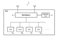
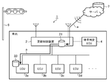
- FIG. 2 is a block diagram illustrating a configuration of an update control system according to Embodiment 1 of the present invention.
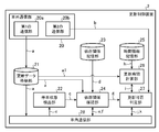
- FIG. 2 is a block diagram illustrating a configuration of an update control device according to the first embodiment.
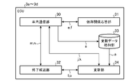
- FIG. 2 is a block diagram illustrating a configuration of a vehicle-mounted ECU according to the first embodiment.
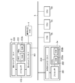
- FIG. 2 is a block diagram illustrating a hardware configuration that executes software for realizing the functions of the update control system according to the first embodiment.
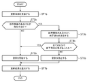
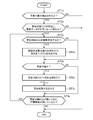
- 5 is a flowchart showing an operation of the update control system according to the first embodiment.
- 5 is a flowchart illustrating an update control method according to the first embodiment.
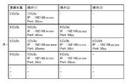
- FIG. 3 is a diagram illustrating an example of dependency relationship information according to the first embodiment.
- FIG. 4 is an explanatory diagram illustrating a process of checking the dependency of the on-vehicle ECU according to the first embodiment.
- FIG. 5 is a diagram showing an example of time information required for an update target ECU to update in the first embodiment.
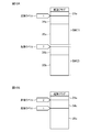
- FIG. 10A is a diagram illustrating a configuration of a memory area of a ROM included in the ECU to be updated.
- FIG. 10B is a diagram illustrating a configuration of a memory area of a ROM included in an ECU having a dependency relationship with the ECU to be updated.
- 5 is a flowchart illustrating an update process of an update target ECU according to the first embodiment.
- FIG. 4 is an explanatory diagram illustrating processing from termination of communication between ECUs to notification of an update result according to the first embodiment; FIG.
- FIG. 5 is an explanatory diagram showing a download process of update data according to the first embodiment.
- 9 is a flowchart illustrating an update control method according to Embodiment 2 of the present invention.
- 13 is a flowchart illustrating an update control method according to Embodiment 3 of the present invention.
- FIG. 1 is a block diagram showing a configuration of an update control system 1 according to Embodiment 1 of the present invention.
- the update control system 1 is a system that controls updating of an ECU to be updated among the ECUs 3a to 3d (vehicle-mounted electronic control devices) mounted on the vehicle.
- ECUs 3a to 3d vehicle-mounted electronic control devices mounted on the vehicle.
- an update control device 2 and a stop determination ECU Is provided.
- the update control device 2 receives the update data of the ECU to be updated by wireless communication while the vehicle is traveling, and stops after the vehicle is once stopped by turning on a red signal of a traffic light or descending of a circuit breaker at a railroad crossing.
- the ECU to be updated is updated within the stop time until the start of the operation.
- the update data is update data of firmware or software provided in the vehicle-mounted ECU.
- a full image update or a difference image update is used as an update method.
- the update control device 2 has a function of performing wired communication and wireless communication, and has a gateway function for connecting to a different network.
- the wireless communication includes data mobile communication such as LTE or 3G, WiFi, Bluetooth (registered trademark), road-to-vehicle communication, and vehicle-to-vehicle communication.
- Examples of the wired communication include Ethernet (registered trademark), CAN (Controller Area Network), MOST (Media Oriented Systems Transport), and LIN (Local Interconnect Network).
- the ECUs 3a to 3d are electronic control units that control various on-vehicle devices mounted on the vehicle.
- the ECU 3a is an ECU that realizes a control system of an accelerator operation, a brake operation, a steering wheel operation, a vehicle interior lighting, and a headlight
- the ECU 3b uses an external camera, a vehicle interior camera, and a corner sensor to perform an ADAS (Advanced Driver Assistance System). ).
- ADAS Advanced Driver Assistance System
- the update control device 2 inquires an ECU having a dependency relationship with the update target ECU about whether or not the update can be executed. If a response indicating that the update can be executed is confirmed, the update time required for the update to be completed and the stop time are updated. It is determined whether the update of the update target ECU is completed within the stop time.
- the dependency relationship between ECUs is a relationship in which communication is performed between ECUs, and the other ECU performs arithmetic processing using information received from one ECU.
- the ECU 3c is an ECU that calculates the vehicle speed
- the ECU 3d is an ECU that corrects the current position of the vehicle using the vehicle speed
- the ECU 3d corrects the current position of the vehicle using the vehicle speed received from the ECU 3c. Therefore, when the transmission of the vehicle speed signal from the ECU 3c is interrupted, the ECU 3d may be erroneously recognized as an emergency in which the communication line with the ECU 3c is disconnected.
- the update control device 2 inquires of the ECUs that have a dependency relationship with the update target ECU about whether or not the update can be performed, and when there is a response indicating that the update can be performed, updates the target ECU.
- the update of the update target ECU is executed, the communication with the ECU having a dependency on the update is shut down. For this reason, an inquiry about whether or not the update target ECU can be updated can be regarded as an inquiry about whether or not the update target ECU can be shut down from the ECUs having a dependency relationship.
- the stop determination ECU 4 monitors the traffic signal or the level crossing in front of the vehicle and the vehicle speed to determine whether the vehicle has stopped due to the lighting of the red signal of the traffic signal or the descending of the level crossing barrier. For example, the stop determination ECU 4 controls the camera outside the vehicle to recognize the light color of the traffic light or the state of the circuit breaker at the level crossing from the image in front of the vehicle, and recognizes the vehicle speed from the vehicle speed sensor or the brake operation. It is determined whether or not the vehicle has been stopped by turning on a traffic light or lowering the level crossing barrier. When determining that the vehicle has stopped, the stop determination ECU 4 transmits a stop state notification indicating the determination result to the update control device 2 by in-vehicle communication.
- FIG. 2 is a block diagram showing the configuration of the update control device 2.
- the update control device 2 includes an external communication unit 20, an update data storage unit 21, a stop state detection unit 22, a dependence relationship storage unit 23, a dependence relationship confirmation unit 24, a time information storage unit 25, and an update time calculation unit 26.
- the external communication unit 20 is a communication unit that communicates with an external device by wireless communication, and includes a first communication unit 20a and a second communication unit 20b.
- the first communication unit 20a connects to a wireless network by wireless communication such as LTE or 3G, and acquires update data a from an external device connected to the wireless network.
- the external device is, for example, a server that manages update data of firmware or software provided in the ECU.
- the server transmits update data a including information indicating the firmware or software to be updated and an update program to the update control device 2.
- the update control device 2 specifies an update target ECU from the ECUs 3a to 3d based on the update data a received from the server.
- the second communication unit 20b is a stop time obtaining unit that obtains the stop time b of the vehicle using road-to-vehicle communication or vehicle-to-vehicle communication.
- the stop time b is the time from when the vehicle stops once to when the vehicle starts running.
- the second communication unit 20b may receive the stop time b from a traffic signal or a roadside wireless communication device provided at a railroad crossing by road-to-vehicle communication.
- the roadside wireless communication device is an external device that manages the time during which the red signal of the traffic light is turned on or the time when the crossing barrier at the railroad crossing is descending as the stop time b.
- the second communication unit 20b determines the stop time b by the inter-vehicle communication from the on-vehicle device of the preceding vehicle. May be acquired.
- the update data storage unit 21 is a storage unit that stores the update data a of the update target ECU.
- the update data a received from the server by the first communication unit 20a is stored in the update data storage unit 21.
- the stop state detection unit 22 detects the stop state of the vehicle based on whether or not the stop state notification c from the stop determination ECU 4 has been received.
- the stopped state of the vehicle is a state in which the vehicle is temporarily stopped due to lighting of a red light of a traffic light or dropping of a circuit breaker at a railroad crossing.
- the stop state detection unit 22 detects whether the vehicle is in a stop state based on the stop state notification c received from the stop determination ECU 4 by the in-vehicle communication unit 28, and determines whether the vehicle is in a stop state if the vehicle is in a stop state.
- the notification c is output to the dependency check unit 24.
- the dependency storage unit 23 stores dependency information d indicating a dependency between ECUs of the ECUs 3a to 3d connected to the update control device 2.
- the dependency information d is table information in which information indicating the dependency between ECUs is associated with each ECU.
- the information indicating the dependency between ECUs includes, for example, a destination address in communication between ECUs.
- the dependency check unit 24 inquires of the ECUs 3a to 3d that have a dependency with the update target ECU whether the update target ECU can be updated. For example, the dependency check unit 24 checks the ECU to be updated with reference to the update data a stored in the update data storage unit 21, and determines the ECU of the vehicle based on the stop state notification c input from the stop state detection unit 22. Check the stop condition. The dependency checking unit 24 specifies an ECU having a dependency with the ECU to be updated based on the dependency information d stored in the dependency storage 23. Using the in-vehicle communication unit 28, the dependency relationship checking unit 24 transmits inquiry information e to an ECU having a dependency relationship with the update target ECU to inquire whether the update of the update target ECU can be performed.
- the ECU that has a dependency with the update target ECU transmits response information f to the inquiry information e to the update control device 2.
- the dependency check unit 24 generates response content information g indicating the content of the response information f received by the in-vehicle communication unit 28 and outputs the generated response content information g to the update availability determination unit 27.
- the response content information g is used as a condition by which the update availability determination unit 27 determines whether or not the update is available.
- the time information storage unit 25 stores the start time of the ECU connected to the update control device 2, the end time of the ECU, and time information h, which is a memory writing speed, in association with each ECU.
- the start time of the ECU and the end time of the ECU include the start time of the OS and the end time of the OS if the ECU has an operating system (OS).
- the end time also includes a communication end process between ECUs.
- the update time calculation unit 26 refers to the time information h stored in the time information storage unit 25 and the data size a1 of the update data a stored in the update data storage unit 21 to update the update target ECU. Calculate the required update time i.
- the update availability determination unit 27 determines whether the update of the update target ECU is completed within the stop time b. For example, when the response content information g input from the dependency check unit 24 indicates that the update is executable, the update availability determination unit 27 calculates the stop time b and the update time calculation acquired by the second communication unit 20b. The update time i calculated by the unit 26 is compared to determine whether or not the update of the update target ECU is completed within the stop time b.
- the in-vehicle communication unit 28 communicates with each of the ECUs 3a to 3d and the stop determination ECU 4 via wired communication such as CAN. For example, the in-vehicle communication unit 28 transmits the inquiry information e from the dependency checking unit 24 to ECUs that have a dependency with the ECU to be updated, and receives response information f from these ECUs. Further, the in-vehicle communication unit 28 transmits the update request j from the update availability determination unit 27 to the update target ECU, and receives the update result information k from the update target ECU.
- FIG. 3 is a block diagram showing the configuration of the vehicle-mounted ECU, and shows the functional configuration of the ECUs 3a to 3d shown in FIG.
- each of the ECUs 3a to 3d includes an in-vehicle communication unit 30, a dependency response unit 31, an end confirmation unit 32, and an update unit 34.
- the in-vehicle communication unit 30 communicates with other ECUs and the update control device 2 via wired communication such as CAN.
- the dependency relation response unit 31 generates response information f for the inquiry information e received by the in-vehicle communication unit 30, and transmits the response information f to the update control device 2 using the in-vehicle communication unit 30.
- the termination confirmation unit 32 confirms termination of communication with a dependent ECU when the ECU on which the ECU is mounted is the update target ECU. For example, upon receiving the communication termination request 1 from the updating unit 34, the termination confirmation unit 32 transmits a communication termination notification m to the ECU having a dependency using the in-vehicle communication unit 30. Upon receiving the communication end notification m, the end confirmation unit 32 included in the ECU having the dependency relationship generates response information n indicating whether communication with the update target ECU can be ended, and sends the response information n to the update target ECU using the in-vehicle communication unit 30. Send.
- the end confirmation unit 32 included in the ECU to be updated receives the response information n received from the ECU having a dependency relationship received by the in-vehicle communication unit 30 and outputs information o indicating the content of the response information n to the update unit 34. .
- the update data storage unit 33 is a storage unit that stores the update data a of the update target ECU. Before the update is started by the update request j, the update data a may be stored in the update data storage unit 33.
- the update unit 34 performs a firmware or software update process of the ECU using the update data a stored in the update data storage unit 33. For example, when the update request j is received from the update control device 2 by the in-vehicle communication unit 30 and the information o indicating that the communication with the dependent ECU is permitted to be ended is obtained by the end confirmation unit 32, Then, an update process is performed using the update data a.
- the update unit 34 uses the in-vehicle communication unit 30 to transmit update result information k indicating the result of the update process to the update control device 2.
- the update control device 2 includes a processing circuit for executing processing from step ST1a to step ST8a described later with reference to FIG.
- the processing circuit may be dedicated hardware, or may be a CPU (Central Processing Unit) that executes a program stored in the memory.
- the update control device 2 includes a processing circuit for executing processing from step ST1b to step ST7b, which will be described later with reference to FIG.
- the processing circuit may be dedicated hardware, or may be a CPU that executes a program stored in a memory.
- FIG. 4 is a block diagram showing a hardware configuration for executing software for realizing the functions of the update control system 1.
- the update control device 2 and the ECUs 3a to 3d are connected to each other by a communication bus 5.
- the outside network interface 100 is an interface (hereinafter, referred to as an I / F) for communication connection with a network outside the vehicle.
- the outside-vehicle network I / F 100 is a road-to-vehicle I / F for communicating with a roadside wireless communication device provided on the roadside near a traffic signal or a railroad crossing, and further has a wireless connection for communication connection with a communication network such as the Internet. Communication I / F.
- Examples of the wireless communication I / F include LTE, 3G, WiFi, and Bluetooth (registered trademark) I / Fs.
- Information transmitted and received between the first communication unit 20a and the second communication unit 20b illustrated in FIG. 2 and the external device is relayed by the external network I / F 100.
- the in-vehicle network I / F 101 and the in-vehicle network I / F 200 are I / Fs for performing wired communication between ECUs via the in-vehicle network.
- the in-vehicle network I / F 101 and the in-vehicle network I / F 200 include CAN, Ethernet (registered trademark), MOST, and LIN I / Fs.
- Information transmitted and received between the in-vehicle communication unit 28 shown in FIG. 2 and the in-vehicle communication unit 30 shown in FIG. 3 is relayed by the in-vehicle network I / F 101 and the in-vehicle network I / F 200.
- the processing circuit may be, for example, a single circuit, a composite circuit, a programmed processor, a parallel programmed processor, or an ASIC (Application / Specific / Integrated / Circuit). ), An FPGA (Field-Programmable Gate Array), or a combination thereof.
- the external communication unit 20 the update data storage unit 21, the stop state detection unit 22, the dependency relationship storage unit 23, the dependency relationship confirmation unit 24, the time information storage unit 25, the update time calculation unit 26, the update availability determination
- the functions of the unit 27 and the in-vehicle communication unit 28 may be realized by separate processing circuits, or these functions may be collectively realized by one processing circuit.
- the processing circuits include, for example, a single circuit, a composite circuit, a programmed processor, a parallel programmed processor, an ASIC, an FPGA, or A combination of these applies.
- the functions of the in-vehicle communication unit 30, the dependency response unit 31, the end confirmation unit 32, and the update unit 34 provided in the ECUs 3a to 3d may be realized by separate processing circuits. It may be realized by a circuit.
- the external communication unit 20 When the processing circuit that implements the function of the update control device 2 is the processor 102 illustrated in FIG. 4, the external communication unit 20, the update data storage unit 21, the stop state detection unit 22, the dependency relationship storage unit 23, The functions of the dependency check unit 24, the time information storage unit 25, the update time calculation unit 26, the update availability determination unit 27, and the in-vehicle communication unit 28 are realized by software, firmware, or a combination of software and firmware.
- the software or firmware is described as a program and stored in the memory 103.
- the processor 102 reads out and executes the program stored in the memory 103, so that the external communication unit 20, the update data storage unit 21, the stop state detection unit 22, the dependency storage unit 23, the dependency check, The functions of the unit 24, the time information storage unit 25, the update time calculation unit 26, the update availability determination unit 27, and the in-vehicle communication unit 28 are realized. That is, the update control device 2 includes a memory 103 for storing a program that, when executed by the processor 102, results in the processing from step ST1a to step ST8a shown in FIG.
- These programs include an external communication unit 20, an update data storage unit 21, a stop state detection unit 22, a dependency relationship storage unit 23, a dependency relationship confirmation unit 24, a time information storage unit 25, an update time calculation unit 26, and an update availability determination unit.
- 27 causes the computer to execute the procedure or method of the in-vehicle communication unit 28.
- the memory 103 stores the computer in the external communication unit 20, the update data storage unit 21, the stop state detection unit 22, the dependency relationship storage unit 23, the dependency relationship confirmation unit 24, the time information storage unit 25, the update time calculation unit 26, and the update availability. It may be a computer-readable storage medium storing a program for causing it to function as the determination unit 27 and the in-vehicle communication unit 28.
- the processing circuit that realizes the respective functions of the ECUs 3a to 3d is the processor 201 illustrated in FIG. 4, the functions of the in-vehicle communication unit 30, the dependency relation response unit 31, the end confirmation unit 32, and the update unit 34 included in the ECUs 3a to 3d, respectively.
- the functions of the in-vehicle communication unit 30, the dependency relation response unit 31, the end confirmation unit 32, and the update unit 34 included in the ECUs 3a to 3d respectively.
- the software or firmware is described as a program and stored in the memory 202.
- the processor 201 reads out and executes the program stored in the memory 202, thereby realizing the functions of the in-vehicle communication unit 30, the dependency relation response unit 31, the end confirmation unit 32, and the update unit 34, which are provided in the ECUs 3a to 3d, respectively.
- the ECUs 3a to 3d include a memory 202 for storing a program that, when executed by the processor 201, results in the processing of steps ST1b to ST11b shown in FIG.
- the memory 202 may be a computer-readable storage medium storing a program for causing a computer to function as the in-vehicle communication unit 30, the dependency response unit 31, the end confirmation unit 32, and the update unit 34.
- a RAM (Random Access Memory) 103a and a ROM (Read Only Memory) 103b are used as the memory 103.
- the RAM 103a temporarily stores an execution program executed by the processor 102 and data necessary for executing the program.
- An execution program is stored in the ROM 103b.
- the memory 103 includes a nonvolatile memory such as a flash memory, an EPROM (Erasable Programmable Read Only Memory), and an EEPROM (Electrically-EPROM), a magnetic disk, a flexible disk, an optical disk, a compact disk, a mini disk, Or a DVD.
- the RAM 202a and the ROM 202b are used for the memory 202, similarly to the memory 103.
- the RAM 202a temporarily stores an execution program executed by the processor 201 and data required for executing the program.
- the execution program and the program to be updated are stored in the ROM 202b.
- the external communication unit 20 the update data storage unit 21, the stop state detection unit 22, the dependency relationship storage unit 23, the dependency relationship confirmation unit 24, the time information storage unit 25, the update time calculation unit 26, the update availability determination
- a part of the functions of the unit 27 and the in-vehicle communication unit 28 may be realized by dedicated hardware, and a part may be realized by software or firmware.
- the functions of the external communication unit 20 and the internal communication unit 28 are realized by a processing circuit that is a dedicated hardware, and the update data storage unit 21, the stop state detection unit 22, the dependency storage unit 23, the dependency confirmation unit
- the functions of the 24, the time information storage unit 25, the update time calculation unit 26, and the update availability determination unit 27 are realized by the processor 102 reading and executing the program stored in the memory 103.
- the processing circuit can realize the above functions by hardware, software, firmware, or a combination thereof. This is the same for the ECUs 3a to 3d.
- FIG. 5 is a flowchart showing the operation of the update control system 1, and shows a case where one of the ECUs 3a to 3d is an update target ECU.
- the stop determination ECU 4 determines that the vehicle is in the stopped state, and transmits a stop state notification c to the update control device 2.
- the stop state detection unit 22 checks whether the stop state of the vehicle is detected based on whether the stop state notification c from the stop determination ECU 4 is received (step ST1).
- the processing in FIG. 5 is ended. Note that a series of processes shown in FIG. 5 is executed for each stop by a traffic light or the like while the update control device 2 is running.
- the stop state detection unit 22 When the stop state notification c is received and the stop state of the vehicle is detected (step ST ⁇ b>1; YES), the stop state detection unit 22 outputs the stop state notification c to the dependency check unit 24.
- the dependency check unit 24 checks whether an ECU to be updated exists in the ECUs 3a to 3d connected to the update control device 2 and whether the update data a has been downloaded (step ST2). For example, the dependency check unit 24 refers to the update data a stored in the update data storage unit 21 so that the ECU to be updated exists in the ECUs 3a to 3d, and the update data a is stored in the update data storage unit 21. It is checked in 21 whether or not the download has been completed.
- the processing of FIG. 5 is terminated.
- the update data a that can be updated is data that has been downloaded to the update control device 2 while the vehicle is running.
- step ST3 if the update target ECU exists in the ECUs 3a to 3d and the update data a has been downloaded (step ST2; YES), the dependency relationship checking unit 24 and the update availability determination unit 27 update the update target ECU. It is determined whether or not execution is possible (step ST3). Note that this update availability determination will be described in detail with reference to FIG. When the update permission / non-permission determination unit 27 determines that the update of the update target ECU is not executable (step ST3; NO), the processing in FIG. 5 is ended.
- step ST4 When the update availability determination unit 27 determines that the update of the update target ECU is executable (step ST3; YES), the update availability determination unit 27 issues an update request instructing the update target ECU to execute the update (step ST4).
- the update data a Before the update is started by the update request j, the update data a may be stored in the update data storage unit 33.
- the update target ECU executes the firmware or software update process using the update data a received from the update control device 2. Then, the update target ECU uses the in-vehicle communication unit 30 to transmit the update result information k indicating whether or not the update was successful to the update control device 2.
- the in-vehicle communication unit 28 included in the update control device 2 receives the update result information k from the update target ECU (step ST5). If the update result information k indicates that the update was successful, the update of the ECU to be updated is completed. On the other hand, when the update result information k indicates that the update has failed, the series of processes in FIG. 5 is repeatedly executed until the update of the update target ECU is completed.
- FIG. 6 is a flowchart showing the update control method according to the first embodiment, and shows the details of step ST4 shown in FIG.
- the dependency relationship checking unit 24 inquires of the ECUs having a dependency relationship with the update target ECU whether or not the update of the update target ECU can be performed (step ST1a).
- the dependency check unit 24 specifies all ECUs that have a dependency with the update target ECU based on the dependency information d stored in the dependency storage unit 23.
- FIG. 7 is a diagram showing an example of the dependency information d.
- the destination of the ECU in the in-vehicle communication between the ECUs is set as information indicating the dependency with the ECU to be updated. If the in-vehicle communication is Ethernet (registered trademark), the ECU destination is the IP (Internet Protocol) address and port number of the ECU. If the in-vehicle communication is CAN, the CAN-received by the ECU to which the communication is connected is received. ID.
- the ECU 3a has a dependency (1) of performing in-vehicle communication with the ECU 3c as shown in FIG.
- the ECU to be updated is the ECU 3c
- dependency (1) for performing in-vehicle communication with the ECU 3a
- a dependency (2) for performing in-vehicle communication with the ECU 3b
- a dependency for performing in-vehicle communication with the ECU 3d There is (3).
- the dependency checking unit 24 refers to the dependency information d shown in FIG. 7 to select the ECU 3c and the ECU 3d having a dependency with the ECU 3b from the ECUs 3a, 3c, and 3d. To identify. Subsequently, the dependency check unit 24 outputs the inquiry information e to the in-vehicle communication unit 28, and transmits the inquiry information e to the ECUs 3c and 3d that have a dependency with the ECU 3b to be updated. When a plurality of ECUs are to be inquired, the in-vehicle communication unit 28 may distribute the inquiry information e by broadcast.
- FIG. 8 is an explanatory diagram showing a process for confirming the dependence of the ECU in the first embodiment.
- a description will be given on the assumption that the ECU 3a is an update target and the ECU 3c has a dependency with the ECU 3a. Further, it is assumed that the vehicle is once stopped by the red light of the traffic light 6 and the update data a has been downloaded from the server 7 to the update control device 2.
- the dependency check unit 24 included in the update control device 2 transmits information for inquiring whether there is no problem in updating to the ECU 3a to be updated, using the in-vehicle communication unit 28.
- the dependence response unit 31 included in the ECU 3a to be updated sends the response information f to the update control device 2 using the in-vehicle communication unit 30 as an information communication process (2). Send.
- the dependency response unit 31 manages the communication between the ECU 3a to be updated and the ECU 3b having the dependency in the communication states (A) to (C), and stores the response information f based on the current communication state. Determine the content.
- the communication state (A) is a state in which the ECU 3a is not communicating.
- the communication state (B) is a state in which the ECU 3a periodically communicates with the ECU 3c. In the communication state (B), the ECU 3a does not communicate with the ECU 3c except during the communication cycle. In the communication state (C), the ECU 3a and the ECU 3c are currently communicating, and are performing a process using information obtained by the communication.
- the dependency response unit 31 included in the ECU 3a to be updated specifies a state corresponding to the current communication state from the communication states (A) to (C), and sends response information f indicating the specified communication state to the in-vehicle communication unit 30. Is transmitted to the update control device 2 by using the information communication process (information communication process (2)).
- the dependency check unit 24 included in the update control device 2 transmits the inquiry information e to the ECU 3c having a dependency with the ECU 3a to be updated, using the in-vehicle communication unit 28.
- the dependence response unit 31 included in the ECU 3c transmits the response information f to the update control device 2 using the in-vehicle communication unit 30 as an information communication process (2a).
- the dependency response unit 31 provided in the ECU 3c manages communication with the ECU 3a to be updated in communication states (A) to (C).
- the dependence response unit 31 provided in the ECU 3c specifies a state corresponding to the current communication state from the communication states (A) to (C), and sends response information f indicating the specified communication state to the in-vehicle communication unit 30. And transmits it to the update control device 2 (information communication step (2a)).
- the dependency check unit 24 checks whether or not there is a response indicating that the update can be executed from all ECUs having a dependency with the update target ECU based on the response information f (step ST2a). For example, when the communication state in the response information f is the communication state (A) or the communication state (B), the dependency check unit 24 determines that the response information f indicates that the update is executable, and Is output to the update permission / inhibition determination unit 27 indicating that the execution is possible. On the other hand, if the communication state in the response information f is the communication state (C), the dependency check unit 24 determines that the response information f indicates that update cannot be executed, and the response content indicating that update cannot be executed. The information g is output to the update availability determination unit 27.
- the update permission / inhibition determination section 27 sends the update time i to the update time calculation section 26 so as to calculate the update time i. Instruct.
- the update time calculation unit 26 calculates the update time i of the ECU to be updated (step ST3a). For example, the update time calculation unit 26 refers to the time information h stored in the time information storage unit 25 and the data size a1 of the update data a stored in the update data storage unit 21 to determine the update target ECU. The update time i required for the update is calculated.
- FIG. 9 is a diagram showing an example of time information h according to the first embodiment.
- the time information h shown in FIG. 9 includes an ECU start time (millisecond), a writing speed of the ROM 202b (millisecond / byte), an end time of the operation of the ECU (millisecond), and the number of times the ECU has been started and the number of times the ECU has been ended
- And spare time (milliseconds) are table information associated with each ECU.
- the ROM 202b stores an execution program and an update program.
- the update time calculation unit 26 calculates the update time i according to the following equation (1) using the time information h and the data size a1 of the update data a.
- A is the activation time of the update target ECU
- B is the number of activations of the update target ECU
- C is the writing speed of the ROM 202b included in the update target ECU.
- D is the data size a1 of the update data a.
- E is the end time of the operation of the update target ECU
- F is the end count of the update target ECU
- G is the spare time.
- Update time (ms) (A ⁇ B) + (C ⁇ D) + (E ⁇ F) + G (1)
- the update time i of the ECU 3a is calculated as follows using the time information h and the data size a1 of the update data a shown in FIG. Is done.
- the start time A and the end time E of the ECU may be an average time when the start and end of the ECU are repeated about several tens of times.
- the number of start times B and the number of end times F of the ECU are the number of start and end times in accordance with the reset of the ECU executed by updating the firmware or software of the ECU, and differ depending on the configuration of the memory area of the ROM 202b.
- FIG. 10A is a diagram illustrating a configuration of a memory area of the ROM 202b provided in the update target ECU.
- FIG. 10B is a diagram illustrating a configuration of a memory area of the ROM 202b included in the ECU having a dependency relationship with the ECU to be updated. 10A and 10B, the ECU to be updated is the ECU 3a.
- the ROM 202b includes a memory area 21a, a memory area SW (1), and a memory area SW (2) in addition to a memory area in which a startup flag is stored.
- the memory area 21a functions as the update data storage unit 21, and stores the update data a.
- the memory area SW (1) includes a memory area 34a and a memory area 35a.
- a program for realizing the function of the update unit 34 is stored in the memory area 34a.
- a program that realizes software to be updated other than the update unit 34 is stored.
- the memory area SW (2) includes a memory area 34b and a memory area 35b.
- the memory area 34b stores a program for realizing the function of the update unit 34
- the memory area 35b stores a program for realizing software to be updated other than the update unit 34.
- the processor 201 executes the program stored in the memory area SW (1). That is, when updating the ECU 3a, the program stored in the memory area 34a is executed by the processor 201, and the updating unit 34 is activated.
- the update unit 34 updates the program stored in the memory area SW (2) using the update data a read from the memory area 21a. Thereafter, after the activation label "2" is set at the head address of the updated memory area SW (2), the ECU 3a is reset to validate the update of the program stored in the memory area SW (2). You. That is, the operation of the ECU 3a is terminated and restarted. At this time, the number of terminations and the number of activations of the ECU 3a are each one. When the ECU 3a is restarted, the program stored in the memory area 34b is executed by the processor 201, and the updating unit 34 is started.
- the ROM 202b shown in FIG. 10B includes a memory area 21a, a memory area 34c, and a memory area 35c in addition to the memory area storing the activation flag.
- the memory area 21a functions as the update data storage unit 21, and stores the update data a.
- the memory area 34c stores a program for realizing the function of the update unit 34, and the memory area 35c stores a program for realizing software to be updated other than the update unit 34.
- the processor 201 executes the program stored in the memory area 35c. That is, when the ECU 3a is updated, a program other than the update unit 34 is executed by the processor 201. Therefore, the ECU 3a is reset after the activation label “2” is set to the head address of the memory area 34c. Thus, the operation of the ECU 3a is terminated and restarted.
- the update unit 34 is activated by resetting the ECU 3a.
- the update unit 34 updates the program described in the memory area 35c using the update data a read from the memory area 21a.
- the activation label “1” is set at the head address of the updated memory area 35c, and then the ECU 3a is reset to validate the update of the program stored in the memory area 35c.
- the operation of the ECU 3a is terminated and restarted.
- the contents of the program stored in the memory area 35c are activated.
- the second communication unit 20b provided in the external communication unit 20 acquires the stop time b (step ST4a).
- the second communication unit 20b receives the stop time b from a traffic light or a roadside wireless communication device provided at a railroad crossing.
- the stop time b is a time during which the red signal of the traffic light is on or a time at which the crossing barrier at the level crossing is descending, and the vehicle is temporarily stopped by the lighting of the red signal at the traffic signal or the lowering of the crossing at the level crossing. It is the time from starting to running.
- the stop time b acquired by the second communication unit 20b is output to the update availability determination unit 27.
- the update availability determination unit 27 compares the stop time b input from the second communication unit 20b with the update time i calculated by the update time calculation unit 26 (step ST5a), and determines that the stop time b is the update time i. It is determined whether or not it is longer (step ST6a). When it is determined that the stop time b is less than or equal to the update time i (step ST6a; NO), or when any of the ECUs having a dependency with the update target ECU responds that the update cannot be executed by the dependency check unit 24. (Step ST2a; NO), the update availability determination unit 27 determines that the update of the update target ECU cannot be executed (Step ST7a). Thereafter, the processing in FIG. 6 ends.
- step ST6a when it is determined that the stop time b is longer than the update time i (step ST6a; YES), the update availability determination unit 27 determines that the update of the update target ECU can be performed (step ST8a). Thereafter, the update availability determination unit 27 transmits an update request j instructing the update target ECU to execute the update using the in-vehicle communication unit 28, and ends the processing in FIG.
- FIG. 11 is a flowchart illustrating an update process of the update target ECU according to the first embodiment.
- FIG. 12 is an explanatory diagram illustrating processing from the end of communication between ECUs to the notification of an update result.
- the ECU 3a is an update target and the ECU 3c has a dependency with the ECU 3a.
- the update availability determination unit 27 included in the update control device 2 transmits an update request j for instructing the update target ECU 3a to execute update (see the information communication process (1 shown in FIG. 12). )).
- the in-vehicle communication unit 30 provided in the ECU 3a receives the update request j from the update control device 2 (step ST1b).
- the update request j received by the in-vehicle communication unit 30 is output to the update unit 34.
- the update unit 34 Upon receiving the update request j, the update unit 34 outputs a communication end request 1 to the end confirmation unit 32.
- the termination checking unit 32 included in the ECU 3a determines whether or not there is an ECU that has a dependency relationship with the ECU 3a to be updated among the ECUs 3b to 3d connected to the updating control device 2. Is confirmed (step ST2b). For example, the end confirmation unit 32 confirms whether there is a dependency between the ECU 3a and another ECU based on a communication state between the ECU 3a and another ECU. If the communication state of the ECU 3a is the communication state (A) (a state in which the ECU 3a is not communicating with the ECU) when the update request j from the update control device 2 is received, the processing of step ST3b is omitted. May be.
- the end confirmation unit 32 checks whether there is no problem even if the update target ECU 3a shuts down at this time.
- the communication unit 30 transmits a communication end notification m to the ECU that is dependent on the ECU 3a (step ST3b).
- the communication end notification m is transmitted from the ECU 3a to the ECU 3c (the information communication step (2) in FIG. 12).
- the termination confirmation unit 32 included in the ECU 3c changes the communication state with the ECU 3a to the above-described communication state (A) (a state in which communication is not performed). It controls the in-vehicle communication unit 30. For example, when the ECU 3c and the ECU 3a are communicating in the communication state (B) (periodic communication), the timer for the periodic communication is stopped, and the communication with the ECU 3a is interrupted.
- the end confirmation unit 32 included in the ECU 3c controls the in-vehicle communication unit 30 so that communication with the ECU 3a is not performed until the update of the ECU 3a is completed. Good.
- the termination confirmation unit 32 included in the ECU 3c when the communication with the ECU 3a to be updated can be transited to a communication state that does not cause any problem, indicates that the communication with the ECU 3a to be updated can be terminated. n is transmitted to the ECU 3a to be updated using the in-vehicle communication unit 30 (the information communication step (3) in FIG. 12).
- the end confirmation unit 32 included in the ECU 3a to be updated confirms whether or not responses have been received from all ECUs that are dependent on the ECU 3a (step ST4b).
- the termination confirmation unit 32 confirms whether or not response information n indicating that communication with the ECU 3a can be terminated has been received from all of the dependent ECUs.
- the end confirmation unit 32 outputs information o indicating the content of the response information n to the update unit 34.
- the updating unit 34 determines whether or not response information n indicating that communication with the ECU 3a to be updated can be ended is received based on the information o from the end checking unit 32.
- step ST4b When the response information n indicating that the communication with the ECU 3a can be ended is received from all the dependent ECUs (step ST4b; YES), or there is no ECU dependent on the ECU to be updated. In this case (step ST2b; NO), the updating unit 34 starts updating (step ST5b). Thereby, the update of the firmware or software included in the ECU 3a is started.
- step ST4b when response information n indicating that communication with the ECU 3a cannot be terminated is received from any of the ECUs having a dependency (step ST4b; NO), the update unit 34 determines that the update has failed. A determination is made (step ST6b). When the processing in step ST5b or the processing in step ST6b is completed, the update unit 34 notifies the update result to the update control device 2 (step ST7b). For example, the update unit 34 uses the in-vehicle communication unit 30 to transmit the update result information k indicating the result of the update process to the update control device 2 (the information communication process (4) in FIG. 12).
- FIG. 13 is an explanatory diagram illustrating the download processing of the update data according to the first embodiment.
- the first communication unit 20a included in the update control device 2 downloads the update data a from the server 7 that manages the update data using mobile data communication while the vehicle is running.
- the update data a downloaded by the first communication unit 20a is temporarily stored in the update data storage unit 21 provided in the update control device 2, as shown in FIG.
- the reason that the update data a is temporarily stored in the update data storage unit 21 is that wireless communication between the server 7 and the first communication unit 20a is more unstable than wired communication, and that a plurality of ECUs In the case of, the data size of the update data a increases accordingly, and it is necessary to temporarily store the data.
- the data size is assigned to the update data a stored in the update data storage unit 21 and transmitted to the ECU to be updated by the in-vehicle communication unit 28.
- the ECU to be updated is the ECU 3a.
- the in-vehicle communication unit 30 provided in the ECU 3a stores the update data a in the update data storage unit 33.
- the update unit 34 updates the firmware or software included in the ECU 3a using the update data a stored in the update data storage unit 33.
- the update control device 2 when the update control device 2 according to the first embodiment responds from the ECU having the dependency relationship with the update target ECU that the update can be executed, the update control device 2 stops the vehicle once and starts running. It is determined whether or not the update of the update target ECU is completed within the stop time b. For example, when it is determined that the update of the ECU is completed within the stop time b from when the vehicle stops at a traffic light at the red light of the traffic light or when the circuit breaker at the railroad crossing starts, the update of the ECU is performed. . Thus, the ECU can be updated without intentionally parking the vehicle.
- the second communication unit 20b acquires the stop time b from the external device. For example, the second communication unit 20b acquires, as the stop time b, a time during which the red light of the traffic light is turned on or a time when the crossing barrier at the railroad crossing is descending. Thereby, the update control device 2 can obtain an accurate stop time at a traffic light or a railroad crossing.
- the update control device 2 includes a dependency storage unit 23 in which dependency information d indicating a dependency between ECUs is stored.
- the dependency relationship checking unit 24 inquires of the ECU whose dependency relationship with the update target ECU has been confirmed based on the dependency relationship information d stored in the dependency relationship storage unit 23 whether or not the update of the update target ECU can be performed.
- the update control device 2 can accurately recognize the ECU having a dependency relationship with the update target ECU and inquire whether the update target ECU can be updated.
- the update time calculation unit 26 calculates the update time i based on the time required for shutting down, starting up, and rewriting the memory of the ECU to be updated. Thereby, the update control device 2 can calculate an accurate update time i.
- the update control system 1 has the configuration shown in FIG. 1, so that the ECU can be updated without intentionally parking the vehicle.
- the update control method according to the first embodiment since the series of processes illustrated in FIG. 6 is executed, the ECU can be updated without intentionally parking the vehicle, as described above.
- Embodiment 2 when a plurality of ECUs are to be updated, the order in which the updates are performed is determined according to the priority of the update, and the update is performed for each ECU in the determined order.
- the update availability determination is executed for the update having the higher priority.
- the priority is a value assigned in accordance with the urgency of the update, and the higher the priority, the higher the urgency and the quicker it is necessary to respond.
- the configuration of the update control device according to the second embodiment and the configuration of the update control system according to the second embodiment are the same as those of the first embodiment. Therefore, in the following description, FIG. 1, FIG. 2 and FIG. 3 are referred to for the components of the second embodiment.
- FIG. 14 is a flowchart illustrating an update control method according to Embodiment 2 of the present invention.
- all of the ECUs 3a to 3d are update target ECUs.
- the vehicle is temporarily stopped before the processing of FIG. 14 is executed due to lighting of a red light of a traffic light or dropping of a crossing barrier at a railroad crossing.
- the stop determination ECU 4 determines that the vehicle is in the stopped state, and transmits a stop state notification c to the update control device 2.
- the stop state detection unit 22 checks whether or not the stop state of the vehicle has been detected based on whether or not the stop state notification c from the stop determination ECU 4 has been received (step ST1c). When the stop state notification c is not received and the stop state of the vehicle is not detected (step ST1c; NO), the processing in FIG. 14 ends. Note that a series of processing illustrated in FIG. 14 is periodically executed while the update control device 2 is running.
- the stop state detection unit 22 When the stop state notification c is received and the stop state of the vehicle is detected (step ST1c; YES), the stop state detection unit 22 outputs the stop state notification c to the dependency check unit 24.
- the dependency check unit 24 checks whether an ECU to be updated exists in the ECUs 3a to 3d connected to the update control device 2 and whether the update data a has been downloaded (step ST2c). If the update target ECU does not exist or the update data a has not been downloaded (step ST2c; NO), the processing in FIG. 14 ends.
- step ST3c the dependency check unit 24 checks whether there are a plurality of update target ECUs.
- step ST3c if there is only one ECU to be updated (step ST3c; NO), the process proceeds to step ST5c.
- the dependency check unit 24 notifies this to the update availability determination unit 27.
- the update availability determination unit 27 determines an ECU to be updated from among a plurality of update target ECUs (step ST4c). For example, the update availability determination unit 27 extracts the priority assigned to each update from the update data a stored in the update data storage unit 21, and determines the ECU with the highest update priority as the ECU that performs the update. judge.
- step ST5c determines whether the update of the ECU determined in step ST4c is executable. Note that this update availability determination is the same as the process described with reference to FIG. 6 in the first embodiment.
- step ST5c determines whether the update of the update target ECU is not executable by the update availability determination unit 27 (step ST5c; NO).
- the update availability determination unit 27 determines that the update of the update target ECU is executable (step ST5c; YES)
- the update availability determination unit 27 issues an update request to instruct the update target ECU to execute the update (step ST6c).
- the update availability determination unit 27 transmits the update request j to the update target ECU using the in-vehicle communication unit 28, and transmits the update data a temporarily stored in the update data storage unit 21 to the update target ECU. I do.
- the update target ECU executes the firmware or software update process using the update data a received from the update control device 2. Then, the update target ECU uses the in-vehicle communication unit 30 to transmit the update result information k indicating whether or not the update was successful to the update control device 2.
- the in-vehicle communication unit 28 included in the update control device 2 receives the update result information k from the update target ECU (step ST7c).
- the update availability determination unit 27 determines that the update target ECU that has not been updated remains among the plurality of update target ECUs determined in step ST3c, and the time required to complete the update is the current stop time. It is determined whether or not b remains (step ST8c). For example, the update availability determination unit 27 determines that there is an update target ECU for which the update process has not been executed, and that the time of the difference obtained by subtracting the time required for the immediately preceding update (the update time i in the immediately preceding update) from the stop time b is equal to the threshold. It is determined based on whether it is longer than
- step ST8c If the update target ECUs for which the update process has not been executed remain or the stop time b required for completing the update does not remain (step ST8c; NO), the process in FIG. 14 is terminated. Even in the case where it is determined in step ST5c that the update of the ECU having the highest update priority cannot be performed, the determination of step ST8c is performed, so that the ECU having the highest update priority is assigned in order from the ECU having the next highest update priority. , The execution of the update can be determined.
- the update availability determination unit 27 determines The process returns to step ST3c.
- the update availability determination unit 27 determines, for example, the difference between the update time i and the stop time b in the ECU having the highest update priority minus the time required for the immediately preceding update (the update time i in the immediately preceding update). Compare with time. Then, the update availability determination unit 27 determines that the update can be executed if the difference time is longer than the update time i, and determines that the update cannot be executed if the difference time is equal to or less than the update time.
- the update possibility determination unit 27 determines the update target ECUs within the stop time in the order of the update priority in the order of the update priority. It is determined whether or not the update is completed. As a result, even when a plurality of updates are requested at the same time, the update with the higher priority and the highest priority is performed. Further, a plurality of updates can be performed within the stop time b.
- Embodiment 3 when there is an update performed simultaneously by a plurality of ECUs or an update performed by a plurality of ECUs according to an update order, the total time obtained by adding the update times of the plurality of ECUs is compared with the stop time to determine whether or not the update is possible.
- Execute The configuration of the update control device according to the third embodiment and the configuration of the update control system according to the third embodiment are the same as those of the first embodiment. Therefore, in the following description, FIG. 1, FIG. 2 and FIG. 3 are referred to for the components of the third embodiment.
- firmware or software included in a plurality of ECUs is updated at the same time or updated in accordance with the update order, it is necessary to ensure consistency of the updated versions. For example, consider a case where the ECU 3a and the ECU 3c operate with the same version of software. In this case, it is possible to update the version 1.0.0 of the software included in the ECU 3a to 2.0.0, and to update the version 1.0.0 of the software included in the ECU 3c to 2.0.0. . However, it is not possible to update only the software version of the ECU 3c to 2.0.0 without updating the software version 1.0.0 of the ECU 3a.
- FIG. 15 is a flowchart showing the update control method according to Embodiment 3 of the present invention, and shows a series of processes corresponding to the process of step ST5c in FIG.
- the dependency relationship checking unit 24 inquires of the ECUs having the dependency relationship with the ECU to be updated whether the update of the ECU to be updated is executable (step ST1d). For example, the dependency check unit 24 specifies all ECUs having a dependency for each update target ECU based on the dependency information d stored in the dependency storage unit 23.
- the dependency confirmation unit 24 determines based on the response information f received from the dependent ECU. Then, it is confirmed whether or not there is a response indicating that the update can be executed from all the ECUs having a dependency relationship for each ECU to be updated (step ST2d). For example, when the response information f indicates that the update is executable, the dependency relationship checking unit 24 outputs the response content information g indicating that the update is executable to the update availability determination unit 27. On the other hand, when the response information f indicates that the update cannot be performed, the dependency relationship checking unit 24 outputs the response content information g indicating that the update cannot be performed to the update availability determination unit 27.
- the update time calculation unit 26 shifts to a repetition loop for the number of the update target ECUs. In this repetition loop, the update time calculation unit 26 calculates an update time i for each ECU to be updated (step ST3d).
- the update time calculation unit 26 refers to the time information h stored in the time information storage unit 25 and the data size a1 of the update data a for each update stored in the update data storage unit 21. The update time i required for the update for each update target ECU is calculated.
- the second communication unit 20b included in the external communication unit 20 acquires the stop time b (step ST4d). For example, the second communication unit 20b receives the stop time b from a traffic light or a roadside wireless communication device provided at a railroad crossing. The stop time b acquired by the second communication unit 20b is output to the update availability determination unit 27.
- the update availability determination unit 27 compares the stop time b input from the second communication unit 20b with the total time of the update time i calculated for each update target ECU by the update time calculation unit 26 (step ST5d). It is determined whether or not the stop time b is longer than the total time (step ST6d). When it is determined that the stop time b is equal to or less than the total time (step ST6d; NO), or when any of the ECUs having a dependency with the update target ECU responds that the update cannot be executed by the dependency relationship checking unit 24. (Step ST2d; NO), the update availability determination unit 27 determines that the update of the update target ECU is not executable (Step ST7d).
- step ST6d When it is determined that the stop time b is longer than the total time (step ST6d; YES), the update availability determination unit 27 determines that the update of the update target ECU is executable (step ST8d). Thereafter, the update permission / inhibition determination unit 27 transmits an update request j for instructing the update target ECU to execute the update using the in-vehicle communication unit 28, and ends the processing in FIG.
- step ST7d when it is determined in step ST7d that the update of the update target ECU cannot be performed, the update availability determination unit 27 excludes the ECUs that have been determined to be not executable and the plurality of ECUs having the update order from the update target ECU ( Step ST9d).
- the update availability determination unit 27 determines the update target ECU that has not been updated regardless of the update order. Therefore, when the process of FIG. 15 is completed and the process returns to the process of FIG. 14, the update order is not considered in step ST8c. Are excluded from the update target ECUs.
- the update control device 2 determines whether the update of the plurality of ECUs to be updated is completed within the stop time b.
- the update availability determination unit 27 determines the longest update time i among the update times i calculated for each ECU by the update time calculation unit 26. And whether or not the update of the plurality of ECUs to be updated is completed within the stop time b.
- the ECU can be updated without intentionally parking the vehicle.
- the update availability determination unit 27 updates the update time calculated for each ECU by the update time calculation unit 26.
- the total time of i is calculated, and the total time is compared with the stop time b to determine whether the update of the plurality of ECUs to be updated is completed within the stop time b.
- the update control device can update the in-vehicle ECU without intentionally parking the vehicle, and thus can be used in an update control system that updates the in-vehicle ECU by OTA.
- 1 update control system 2 update control device, 3a, 3b, 3c, 3d ECU, 4 stop judgment ECU, 5 communication bus, 6 traffic light, 7 server, 20 outside communication unit, 20a first communication unit, 20b second Communication unit, 21, 33 update data storage unit, 21a, 34a, 34b, 34c, 35a, 35b, 35c memory area, 22 stop state detection unit, 23 dependency storage unit, 24 dependency confirmation unit, 25 time information storage unit , 26 update time calculation unit, 27 update availability determination unit, 28, 30 in-vehicle communication unit, 31 dependency relation response unit, 32 end confirmation unit, 33 update data storage unit, 34 update unit, 100 external network I / F, 101, 200 ⁇ in-vehicle network I / F, 102, 201 ⁇ processor, 103, 202 ⁇ memory, 103a, 202 RAM, 103b, 202b ROM.
Landscapes
- Engineering & Computer Science (AREA)
- General Engineering & Computer Science (AREA)
- Theoretical Computer Science (AREA)
- Software Systems (AREA)
- Physics & Mathematics (AREA)
- General Physics & Mathematics (AREA)
- Computer Security & Cryptography (AREA)
- Stored Programmes (AREA)
Abstract
更新制御装置(2)は、更新対象の車載用ECUと依存関係のある車載用ECUから、更新の実行可が応答された場合に、車両が一旦停車してから走行を開始するまでの停車時間内に更新対象ECUの更新が完了するか否かを判定する。
Description
本発明は、車両に搭載された車載用電子制御装置(以下、車載用ECUと記載する)の制御プログラムの更新を制御する更新制御装置、更新制御システムおよび更新制御方法に関する。
近年、無線通信を利用して車載用ECUの制御プログラムを更新するOTA(Over The Air)技術が提案されている。例えば、特許文献1には、車両が駐停車される時間を予測し、予測した時間に無線通信を利用して車載用ECUのプログラムを更新する制御装置が記載されている。
特許文献1に記載される制御装置では、車両が駐車されてエンジンが停止された時間帯に更新プログラムが車載装置に書き込まれる。このため、早急に対処しなければならない緊急性の高い更新があった場合、車両の走行を中断して一旦駐車させる必要があるため、運転者にとって煩わしく、OTAの利便性が損なわれるという課題があった。
本発明は上記課題を解決するものであり、車両を意図的に駐車させずに、車載用ECUを更新することができる更新制御装置、更新制御システムおよび更新制御方法を得ることを目的とする。
本発明に係る更新制御装置は、依存関係確認部、更新時間計算部、停車時間取得部および更新可否判定部を備えている。依存関係確認部は、更新対象の車載用ECUと依存関係のある車載用ECUに対して更新対象のECUの更新の実行可否を問い合わせる。更新時間計算部は、更新対象のECUの更新に必要な更新時間を計算する。停車時間取得部は、車両が一旦停車してから走行を開始するまでの停車時間を取得する。更新可否判定部は、依存関係確認部によって更新の実行可の応答が確認された場合に、更新時間と停車時間とを比較して、停車時間内に更新対象のECUの更新が完了するか否かを判定する。
本発明によれば、更新対象の車載用ECUと依存関係のある車載用ECUから、更新の実行可が応答された場合に、車両が一旦停車してから走行を開始するまでの停車時間内に更新対象の車載用ECUの更新が完了するか否かを判定する。これにより、車両を意図的に駐車させずに、車両の停車時間内に車載用ECUを更新することができる。
以下、本発明をより詳細に説明するため、本発明を実施するための形態について、添付の図面に従って説明する。
実施の形態1.
図1は、本発明の実施の形態1に係る更新制御システム1の構成を示すブロック図である。更新制御システム1は、車両に搭載されたECU3a~3d(車載用電子制御装置)のうちの更新対象ECUの更新を制御するシステムであり、ECU3a~3dに加え、更新制御装置2および停車判定ECUを備える。更新制御装置2は、車両が走行している間に更新対象ECUの更新データを無線通信で受信して、信号機の赤信号の点灯または踏切の遮断機の降下によって車両が一旦停車してから走行を開始するまでの停車時間内に更新対象ECUを更新する。更新データとは、車載用ECUが備えるファームウェアまたはソフトウェアの更新データである。また、更新方法には、フルイメージ更新または差分イメージ更新が利用される。
実施の形態1.
図1は、本発明の実施の形態1に係る更新制御システム1の構成を示すブロック図である。更新制御システム1は、車両に搭載されたECU3a~3d(車載用電子制御装置)のうちの更新対象ECUの更新を制御するシステムであり、ECU3a~3dに加え、更新制御装置2および停車判定ECUを備える。更新制御装置2は、車両が走行している間に更新対象ECUの更新データを無線通信で受信して、信号機の赤信号の点灯または踏切の遮断機の降下によって車両が一旦停車してから走行を開始するまでの停車時間内に更新対象ECUを更新する。更新データとは、車載用ECUが備えるファームウェアまたはソフトウェアの更新データである。また、更新方法には、フルイメージ更新または差分イメージ更新が利用される。
更新制御装置2は、有線通信および無線通信を行う機能を有し、異なるネットワークと接続するためのゲートウェイ機能を有する。ここで、無線通信には、LTEまたは3Gといったデータモバイル通信、WiFi、Bluetooth(登録商標)、路車間通信、車車間通信がある。有線通信には、例えば、イーサネット(登録商標)、CAN(Controller Area Network)、MOST(Media Oriented Systems Transport)、LIN(Local Interconnect Network)がある。
ECU3a~3dは、車両に搭載されている様々な車載機器を制御する電子制御装置である。例えば、ECU3aは、アクセル操作、ブレーキ操作、ハンドル操作、車内照明、ヘッドライトの制御系を実現するECUであり、ECU3bは、車外カメラ、車内カメラおよびコーナーセンサを用いて、ADAS(Advanced Driver Assistance System)を実現するECUである。
更新制御装置2は、更新対象ECUと依存関係のあるECUに対して更新の実行可否を問い合わせ、更新の実行可の応答が確認された場合に、更新完了までに必要な更新時間と上記停車時間とを比較して、停車時間内に更新対象ECUの更新が完了するか否かを判定する。ここで、ECU間の依存関係とは、ECU間で通信を行い、一方のECUから受信した情報を用いて他方のECUが演算処理を行う関係である。
例えば、ECU3cが車速を算出するECUであり、ECU3dが車速を用いて車両の現在位置を補正するECUである場合には、ECU3cとECU3dとの間に依存関係がある。この場合、ECU3dは、ECU3cから受信した車速を用いて車両の現在位置を補正する。このため、ECU3cからの車速信号の送信が途絶えた場合、ECU3dは、ECU3cとの通信線が断線した緊急事態であると誤認識される可能性がある。
ECUが備えるファームウェアまたはソフトウェアの更新では、更新後のプログラムを有効化するためにECUのリセット(動作の停止と再起動)を行う必要があり、更新前にECU間で行っていた通信を中断しなければならない。そこで、更新制御装置2は、更新対象ECUと依存関係のあるECUに対して更新の実行可否を問い合わせ、更新の実行可を示す応答があった場合に、更新対象ECUの更新を実行させる。なお、更新対象ECUの更新が実行されると、これと依存関係のあるECUとの通信がシャットダウンされる。このため、依存関係のあるECUからは、更新対象ECUの更新の実行可否の問い合わせが、更新対象ECUのシャットダウンの可否の問い合わせとみなせる。
停車判定ECU4は、車両前方の信号機または踏切と車速とを監視することで、信号機の赤信号の点灯または踏切の遮断機の降下によって車両が停車したか否かを判定する。
例えば、停車判定ECU4は、車外カメラを制御して車両前方の映像から信号機の灯色または踏切の遮断機の状態を画像認識し、車速センサまたはブレーキ操作から車速を認識することで、信号機の赤信号の点灯または踏切の遮断機の降下によって車両が停車されたか否かを判定する。停車判定ECU4は、車両が停車したと判定すると、この判定結果を示す停車状態通知を、車内通信で更新制御装置2に送信する。
例えば、停車判定ECU4は、車外カメラを制御して車両前方の映像から信号機の灯色または踏切の遮断機の状態を画像認識し、車速センサまたはブレーキ操作から車速を認識することで、信号機の赤信号の点灯または踏切の遮断機の降下によって車両が停車されたか否かを判定する。停車判定ECU4は、車両が停車したと判定すると、この判定結果を示す停車状態通知を、車内通信で更新制御装置2に送信する。
図2は、更新制御装置2の構成を示すブロック図である。図2において、更新制御装置2は、車外通信部20、更新データ格納部21、停車状態検出部22、依存関係記憶部23、依存関係確認部24、時間情報記憶部25、更新時間計算部26、更新可否判定部27および車内通信部28を備える。車外通信部20は、無線通信で外部装置と通信を行う通信部であり、第1の通信部20aおよび第2の通信部20bを備える。
第1の通信部20aは、LTEまたは3Gといった無線通信で無線ネットワークに接続し、無線ネットワークに接続された外部装置から更新データaを取得する。外部装置は、例えば、ECUが備えるファームウェアまたはソフトウェアの更新データを管理しているサーバである。サーバは、ECUの更新を行うときに、更新対象のファームウェアまたはソフトウェアを示す情報と更新プログラムとを含む更新データaを更新制御装置2に送信する。更新制御装置2は、サーバから受信した更新データaに基づいてECU3a~3dの中から更新対象ECUを特定する。
第2の通信部20bは、路車間通信または車車間通信を用いて車両の停車時間bを取得する停車時間取得部である。停車時間bは、車両が一旦停車してから走行を開始するまでの時間である。例えば、第2の通信部20bは、路車間通信によって、信号機または踏切に設けられた路側無線通信機から停車時間bを受信してもよい。ここで、路側無線通信機は、信号機の赤信号が点灯している時間または踏切の遮断機が降下している時間を、停車時間bとして管理する外部装置である。なお、車両前方を走行する先行車両に搭載された車載装置によって停車時間bが取得されていた場合、第2の通信部20bは、先行車両の上記車載装置から、車車間通信で停車時間bを取得してもよい。
更新データ格納部21は、更新対象ECUの更新データaが格納される記憶部である。第1の通信部20aによって上記サーバから受信された更新データaは、更新データ格納部21に格納される。
停車状態検出部22は、停車判定ECU4からの停車状態通知cを受信したか否かに基づいて車両の停車状態を検出する。ここで、車両の停車状態とは、信号機の赤信号の点灯または踏切の遮断機の降下によって車両が一旦停車した状態である。停車状態検出部22は、車内通信部28によって停車判定ECU4から受信された停車状態通知cに基づいて車両が停車状態であるか否かを検出し、車両が停車状態である場合に、停車状態通知cを依存関係確認部24に出力する。
依存関係記憶部23は、更新制御装置2に接続されているECU3a~3dのECU間の依存関係を示す依存関係情報dを記憶する。依存関係情報dは、ECU同士の依存関係を示す情報がECUごとに対応付けられたテーブル情報である。ECU同士の依存関係を示す情報には、例えば、ECU間の通信における宛先アドレスがある。
依存関係確認部24は、ECU3a~3dのうち、更新対象ECUと依存関係のあるECUに対して更新対象ECUの更新の可否を問い合わせる。例えば、依存関係確認部24は、更新データ格納部21に格納された更新データaを参照して更新対象のECUを確認し、停車状態検出部22から入力した停車状態通知cに基づいて車両の停車状態を確認する。依存関係確認部24は、依存関係記憶部23に記憶された依存関係情報dに基づいて更新対象ECUと依存関係のあるECUを特定する。依存関係確認部24は、車内通信部28を用いて、更新対象ECUと依存関係のあるECUに対して更新対象ECUの更新の実行可否を問い合わせる問い合わせ情報eを送信する。
更新対象ECUと依存関係のあるECUでは、問い合わせ情報eに対する応答情報fを更新制御装置2に送信する。依存関係確認部24は、車内通信部28によって受信された応答情報fの内容を示す応答内容情報gを生成して更新可否判定部27に出力する。応答内容情報gは、更新可否判定部27による更新可否の判定条件として利用される。
時間情報記憶部25には、更新制御装置2に接続されているECUの起動時間、ECUの終了時間、およびメモリ書き込み速度である時間情報hがECUごとに対応付けて記憶されている。ここで、ECUの起動時間およびECUの終了時間には、オペレーティングシステム(OS)が搭載されたECUであれば、OSの起動時間およびOSの終了時間も含まれる。また、終了時間には、ECU間の通信終了処理も含まれる。更新時間計算部26は、時間情報記憶部25に記憶されている時間情報hと更新データ格納部21に格納されている更新データaのデータサイズa1とを参照して、更新対象ECUの更新に必要な更新時間iを計算する。
更新可否判定部27は、停車時間b内に更新対象ECUの更新が完了するか否かを判定する。例えば、更新可否判定部27は、依存関係確認部24から入力した応答内容情報gが更新の実行可を示していた場合に、第2の通信部20bによって取得された停車時間bと更新時間計算部26によって算出された更新時間iとを比較して、停車時間b内に更新対象ECUの更新が完了するか否かを判定する。
車内通信部28は、CANなどの有線通信を介して、ECU3a~3dおよび停車判定ECU4の各々と通信する。例えば、車内通信部28は、依存関係確認部24からの問い合わせ情報eを更新対象ECUと依存関係のあるECUに送信して、これらのECUからの応答情報fを受信する。また、車内通信部28は、更新可否判定部27からの更新依頼jを更新対象ECUへ送信して、更新対象ECUからの更新結果情報kを受信する。
図3は、車載用ECUの構成を示すブロック図であり、図1に示したECU3a~3dの機能構成を示している。ECU3a~3dのそれぞれは、図3に示すように、車内通信部30、依存関係応答部31、終了確認部32および更新部34を備えている。車内通信部30は、CANなどの有線通信を介して他のECUおよび更新制御装置2と通信する。依存関係応答部31は、車内通信部30によって受信された問い合わせ情報eに対する応答情報fを生成し、車内通信部30を用いて応答情報fを更新制御装置2に送信する。
終了確認部32は、自身を搭載するECUが更新対象ECUである場合に、依存関係のあるECUとの通信の終了を確認する。例えば、終了確認部32は、更新部34から通信終了依頼lを入力すると、車内通信部30を用いて依存関係のあるECUに対して通信終了通知mを送信する。依存関係のあるECUが備える終了確認部32は、通信終了通知mを受信すると、更新対象ECUとの通信の終了可否を示す応答情報nを生成し、車内通信部30を用いて更新対象ECUに送信する。更新対象ECUが備える終了確認部32は、車内通信部30によって受信された、依存関係のあるECUからの応答情報nを入力し、応答情報nの内容を示す情報oを更新部34に出力する。
更新データ格納部33は、更新対象ECUの更新データaが格納される記憶部である。更新依頼jによる更新開始前に、更新データ格納部33に更新データaを格納しておいてもよい。
更新部34は、更新データ格納部33に格納された更新データaを用いて、ECUが備えるファームウェアまたはソフトウェア更新処理を行う。例えば、更新部34は、車内通信部30によって更新制御装置2からの更新依頼jが受信され、終了確認部32によって依存関係のあるECUとの通信の終了可を示す情報oが得られた場合に、更新データaを用いて更新処理を行う。更新部34は、車内通信部30を用いて、更新処理の結果を示す更新結果情報kを更新制御装置2に送信する。
次に、更新制御システム1の機能を実現するハードウェア構成について説明する。
更新制御装置2における、車外通信部20、更新データ格納部21、停車状態検出部22、依存関係記憶部23、依存関係確認部24、時間情報記憶部25、更新時間計算部26、更新可否判定部27および車内通信部28の機能は、処理回路によって実現される。すなわち、更新制御装置2は、図6を用いて後述するステップST1aからステップST8aまでの処理を実行するための処理回路を備える。処理回路は、専用のハードウェアであってもよいが、メモリに記憶されたプログラムを実行するCPU(Central Processing Unit)であってもよい。
更新制御装置2における、車外通信部20、更新データ格納部21、停車状態検出部22、依存関係記憶部23、依存関係確認部24、時間情報記憶部25、更新時間計算部26、更新可否判定部27および車内通信部28の機能は、処理回路によって実現される。すなわち、更新制御装置2は、図6を用いて後述するステップST1aからステップST8aまでの処理を実行するための処理回路を備える。処理回路は、専用のハードウェアであってもよいが、メモリに記憶されたプログラムを実行するCPU(Central Processing Unit)であってもよい。
ECU3a~3dがそれぞれ備える、車内通信部30、依存関係応答部31、終了確認部32および更新部34の機能は、処理回路によって実現される。すなわち、更新制御装置2は、図11を用いて後述するステップST1bからステップST7bまでの処理を実行するための処理回路を備える。処理回路は、専用のハードウェアであってもよいが、メモリに記憶されたプログラムを実行するCPUであってもよい。
図4は、更新制御システム1の機能を実現するソフトウェアを実行するハードウェア構成を示すブロック図である。図4において、更新制御装置2およびECU3a~3dは、通信バス5によって互いに接続されている。車外ネットワークインタフェース100は、車外のネットワークと通信接続するためのインタフェース(以下、I/Fと記載する)である。例えば、車外ネットワークI/F100は、信号機または踏切の近傍の路側に設けられた路側無線通信機と通信するための路車間I/Fであり、さらにインターネットなどの通信ネットワークと通信接続するための無線通信I/Fである。無線通信I/Fには、LTE、3G、WiFi、Bluetooth(登録商標)のI/Fが挙げられる。図2に示した第1の通信部20aおよび第2の通信部20bと車外装置との間で送受信される情報は、車外ネットワークI/F100によって中継される。
車内ネットワークI/F101および車内ネットワークI/F200は、車内のネットワークを介してECU間で有線通信を行うためのI/Fである。例えば、車内ネットワークI/F101および車内ネットワークI/F200には、CAN、イーサネット(登録商標)、MOST、LINのI/Fが挙げられる。図2に示した車内通信部28と図3に示した車内通信部30との間で送受信される情報は、車内ネットワークI/F101および車内ネットワークI/F200によって中継される。
更新制御装置2の機能を実現する処理回路が専用のハードウェアである場合、処理回路は、例えば、単一回路、複合回路、プログラム化したプロセッサ、並列プログラム化したプロセッサ、ASIC(Application Specific Integrated Circuit)、FPGA(Field-Programmable Gate Array)、またはこれらを組み合わせたものが該当する。更新制御装置2における、車外通信部20、更新データ格納部21、停車状態検出部22、依存関係記憶部23、依存関係確認部24、時間情報記憶部25、更新時間計算部26、更新可否判定部27および車内通信部28の機能を、別々の処理回路で実現してもよく、これらの機能をまとめて1つの処理回路で実現してもよい。
ECU3a~3dのそれぞれの機能を実現する処理回路が専用のハードウェアである場合、処理回路は、例えば、単一回路、複合回路、プログラム化したプロセッサ、並列プログラム化したプロセッサ、ASIC、FPGA、またはこれらを組み合わせたものが該当する。ECU3a~3dがそれぞれ備える、車内通信部30、依存関係応答部31、終了確認部32および更新部34の機能を、別々の処理回路で実現してもよく、これらの機能をまとめて1つの処理回路で実現してもよい。
更新制御装置2の機能を実現する処理回路が図4に示すプロセッサ102である場合、更新制御装置2における車外通信部20、更新データ格納部21、停車状態検出部22、依存関係記憶部23、依存関係確認部24、時間情報記憶部25、更新時間計算部26、更新可否判定部27および車内通信部28の機能は、ソフトウェア、ファームウェアまたはソフトウェアとファームウェアとの組み合わせにより実現される。なお、ソフトウェアまたはファームウェアは、プログラムとして記述されてメモリ103に記憶される。
プロセッサ102は、メモリ103に記憶されたプログラムを読み出して実行することにより、更新制御装置2における車外通信部20、更新データ格納部21、停車状態検出部22、依存関係記憶部23、依存関係確認部24、時間情報記憶部25、更新時間計算部26、更新可否判定部27および車内通信部28の機能を実現する。すなわち、更新制御装置2は、プロセッサ102によって実行されるときに、図6に示すステップST1aからステップST8aまでの処理が結果的に実行されるプログラムを記憶するためのメモリ103を備える。
これらのプログラムは、車外通信部20、更新データ格納部21、停車状態検出部22、依存関係記憶部23、依存関係確認部24、時間情報記憶部25、更新時間計算部26、更新可否判定部27および車内通信部28の手順または方法を、コンピュータに実行させる。メモリ103は、コンピュータを、車外通信部20、更新データ格納部21、停車状態検出部22、依存関係記憶部23、依存関係確認部24、時間情報記憶部25、更新時間計算部26、更新可否判定部27および車内通信部28として機能させるためのプログラムが記憶されたコンピュータ可読記憶媒体であってもよい。
ECU3a~3dのそれぞれの機能を実現する処理回路が図4に示すプロセッサ201である場合、ECU3a~3dがそれぞれ備える車内通信部30、依存関係応答部31、終了確認部32および更新部34の機能は、ソフトウェア、ファームウェアまたはソフトウェアとファームウェアとの組み合わせによって実現される。なお、ソフトウェアまたはファームウェアは、プログラムとして記述されてメモリ202に記憶される。
プロセッサ201は、メモリ202に記憶されたプログラムを読み出して実行することによって、ECU3a~3dがそれぞれ備える、車内通信部30、依存関係応答部31、終了確認部32および更新部34の機能を実現する。すなわち、ECU3a~3dは、プロセッサ201によって実行されるときに、図11に示すステップST1bからステップST11bまでの処理が結果的に実行されるプログラムを記憶するためのメモリ202を備える。
これらのプログラムは、車内通信部30、依存関係応答部31、終了確認部32および更新部34の手順または方法を、コンピュータに実行させる。メモリ202は、コンピュータを、車内通信部30、依存関係応答部31、終了確認部32および更新部34として機能させるためのプログラムが記憶されたコンピュータ可読記憶媒体であってもよい。
メモリ103には、RAM(Random Access Memory)103a、およびROM(Read Only Memory)103bが用いられる。RAM103aには、プロセッサ102によって実行される実行プログラムおよびプログラムの実行に必要なデータが一時的に記憶される。ROM103bには、実行プログラムが記憶される。また、メモリ103には、フラッシュメモリ、EPROM(Erasable Programmable Read Only Memory)、EEPROM(Electrically-EPROM)などの不揮発性または揮発性の半導体メモリ、磁気ディスク、フレキシブルディスク、光ディスク、コンパクトディスク、ミニディスク、およびDVDのいずれかを用いてもよい。
メモリ202には、メモリ103と同様に、RAM202aおよびROM202bが用いられる。RAM202aには、プロセッサ201によって実行される実行プログラム、および、プログラムの実行に必要なデータが一時的に記憶される。ROM202bには、実行プログラムおよび更新対象のプログラムが記憶される。
更新制御装置2における、車外通信部20、更新データ格納部21、停車状態検出部22、依存関係記憶部23、依存関係確認部24、時間情報記憶部25、更新時間計算部26、更新可否判定部27および車内通信部28の機能について一部を専用のハードウェアで実現し、一部をソフトウェアまたはファームウェアで実現してもよい。
例えば、車外通信部20および車内通信部28については、専用のハードウェアである処理回路で機能を実現し、更新データ格納部21、停車状態検出部22、依存関係記憶部23、依存関係確認部24、時間情報記憶部25、更新時間計算部26、および更新可否判定部27については、プロセッサ102がメモリ103に記憶されたプログラムを読み出して実行することによって機能を実現する。このように、処理回路は、ハードウェア、ソフトウェア、ファームウェアまたはこれらの組み合わせにより上記機能を実現することができる。これは、ECU3a~3dにおいても同様である。
次に動作について説明する。
図5は、更新制御システム1の動作を示すフローチャートであり、ECU3a~3dのうち、更新対象ECUが1つである場合を示している。また、図5の処理が実行される前に、信号機の赤信号の点灯または踏切の遮断機の降下によって車両が一旦停車した状態であるものとする。このとき、停車判定ECU4は、車両が停車状態であると判定し、更新制御装置2に対して停車状態通知cを送信する。
図5は、更新制御システム1の動作を示すフローチャートであり、ECU3a~3dのうち、更新対象ECUが1つである場合を示している。また、図5の処理が実行される前に、信号機の赤信号の点灯または踏切の遮断機の降下によって車両が一旦停車した状態であるものとする。このとき、停車判定ECU4は、車両が停車状態であると判定し、更新制御装置2に対して停車状態通知cを送信する。
停車状態検出部22は、停車判定ECU4からの停車状態通知cが受信されたか否かに基づいて、車両の停車状態が検出されたか否かを確認する(ステップST1)。ここで、停車状態通知cが受信されず、車両の停車状態が検出されなかった場合(ステップST1;NO)、図5の処理が終了される。なお、図5に示す一連の処理は、更新制御装置2が起動している間、信号機などによる停車ごとに実行される。
停車状態検出部22は、停車状態通知cが受信され、車両の停車状態が検出された場合(ステップST1;YES)、停車状態通知cを依存関係確認部24に出力する。
依存関係確認部24は、更新制御装置2に接続されたECU3a~3dの中に、更新対象のECUが存在し、更新データaがダウンロード済みであるか否かを確認する(ステップST2)。例えば、依存関係確認部24は、更新データ格納部21に格納されている更新データaを参照することにより、ECU3a~3dの中に更新対象のECUが存在し、更新データaが更新データ格納部21にダウンロード済みであるか否かを確認する。
依存関係確認部24は、更新制御装置2に接続されたECU3a~3dの中に、更新対象のECUが存在し、更新データaがダウンロード済みであるか否かを確認する(ステップST2)。例えば、依存関係確認部24は、更新データ格納部21に格納されている更新データaを参照することにより、ECU3a~3dの中に更新対象のECUが存在し、更新データaが更新データ格納部21にダウンロード済みであるか否かを確認する。
ECU3a~3dの中に更新対象ECUが存在しないか、更新データaがダウンロードされていない場合(ステップST2;NO)、図5の処理が終了される。
なお、実施の形態1において、更新処理が可能な更新データaとは、車両の走行中に、更新制御装置2にダウンロードが完了しているデータである。
なお、実施の形態1において、更新処理が可能な更新データaとは、車両の走行中に、更新制御装置2にダウンロードが完了しているデータである。
一方、ECU3a~3dの中に更新対象ECUが存在し、更新データaがダウンロードされていた場合(ステップST2;YES)、依存関係確認部24および更新可否判定部27は、更新対象ECUの更新が実行可能か否かを判定する(ステップST3)。なお、この更新可否判定は、後述する図6を用いて詳細に説明する。更新可否判定部27によって更新対象ECUの更新が実行不可と判定された場合(ステップST3;NO)、図5の処理が終了される。
更新可否判定部27は、更新対象ECUの更新が実行可と判定した場合(ステップST3;YES)、更新対象ECUに対して更新の実行を指示する更新依頼を行う(ステップST4)。更新依頼jによる更新開始前に、更新データ格納部33に更新データaを格納しておいてもよい。
更新対象ECUは、更新制御装置2から受信した更新データaを用いてファームウェアまたはソフトウェアの更新処理を実行する。そして、更新対象ECUは、車内通信部30を用いて、更新に成功したか否かを示す更新結果情報kを更新制御装置2に送信する。
更新制御装置2が備える車内通信部28は、更新対象ECUから更新結果情報kを受信する(ステップST5)。更新結果情報kが更新成功を示していれば、更新対象ECUの更新が完了する。一方、更新結果情報kが更新失敗を示す場合、更新対象ECUの更新が完了するまで、図5の一連の処理が繰り返し実行される。
更新制御装置2が備える車内通信部28は、更新対象ECUから更新結果情報kを受信する(ステップST5)。更新結果情報kが更新成功を示していれば、更新対象ECUの更新が完了する。一方、更新結果情報kが更新失敗を示す場合、更新対象ECUの更新が完了するまで、図5の一連の処理が繰り返し実行される。
次に、更新可否判定処理の詳細について説明する。
図6は、実施の形態1に係る更新制御方法を示すフローチャートであり、図5に示したステップST4の詳細を示している。
まず、依存関係確認部24が、更新対象ECUと依存関係のあるECUに対して、更新対象ECUの更新の実行可否を問い合わせる(ステップST1a)。例えば、依存関係確認部24は、依存関係記憶部23に記憶された依存関係情報dに基づいて更新対象ECUと依存関係のある全てのECUを特定する。
図6は、実施の形態1に係る更新制御方法を示すフローチャートであり、図5に示したステップST4の詳細を示している。
まず、依存関係確認部24が、更新対象ECUと依存関係のあるECUに対して、更新対象ECUの更新の実行可否を問い合わせる(ステップST1a)。例えば、依存関係確認部24は、依存関係記憶部23に記憶された依存関係情報dに基づいて更新対象ECUと依存関係のある全てのECUを特定する。
図7は、依存関係情報dの例を示す図である。図7に示す依存関係情報dには、更新対象ECUとの依存関係を示す情報として、ECU間の車内通信におけるECUの宛先が設定されている。ECUの宛先は、車内通信がイーサネット(登録商標)であれば、ECUのIP(インターネットプロトコル)アドレスおよびポート番号であり、車内通信がCANである場合は、通信接続先のECUが受信するCAN-IDである。
例えば、更新対象ECUがECU3aである場合、ECU3aには、図7に示すようにECU3cとの間で車内通信を行う依存関係(1)がある。一方、更新対象ECUがECU3cであると、依存関係(1)、依存関係(2)および依存関係(3)の3つの依存関係がある。すなわち、更新対象のECU3cは、ECU3aとの間で車内通信を行う依存関係(1)、ECU3bとの間で車内通信を行う依存関係(2)、およびECU3dとの間で車内通信を行う依存関係(3)がある。
依存関係確認部24は、例えば、更新対象ECUがECU3bである場合、図7に示す依存関係情報dを参照することで、ECU3a、ECU3cおよびECU3dの中から、ECU3bと依存関係のあるECU3cおよびECU3dを特定する。続いて、依存関係確認部24は、車内通信部28に問い合わせ情報eを出力して、更新対象のECU3bと依存関係のあるECU3cおよびECU3dに対して問い合わせ情報eを送信する。複数のECUが問い合わせ対象である場合、車内通信部28は、ブロードキャストで問い合わせ情報eを配信してもよい。
図8は、実施の形態1におけるECUの依存関係の確認処理を示す説明図である。図8において、ECU3aが更新対象であり、ECU3cがECU3aと依存関係があるものとして説明する。また、信号機6の赤信号によって車両が一旦停車した状態であり、更新データaは、サーバ7から更新制御装置2にダウンロードされているものとする。
更新制御装置2が備える依存関係確認部24は、情報通信過程(1)として、車内通信部28を用いて、更新に問題がないか否かを問い合わせる情報を更新対象のECU3aに送信する。更新対象のECU3aが備える依存関係応答部31は、車内通信部30によって上記情報が受信されると、情報通信過程(2)として、車内通信部30を用いて応答情報fを更新制御装置2に送信する。
このとき、依存関係応答部31は、更新対象のECU3aと依存関係のあるECU3bとの間の通信を通信状態(A)~(C)で管理し、現在の通信状態に基づいて応答情報fの内容を決定する。通信状態(A)は、ECU3aが通信していない状態である。また、通信状態(B)は、ECU3aがECU3cとの間で定期的に通信する状態である。通信状態(B)では、通信周期以外ではECU3aがECU3cとの通信は行われない。通信状態(C)では、ECU3aとECU3cとが現在通信しており、通信で得られた情報を用いて処理を行っている状態である。更新対象のECU3aが備える依存関係応答部31は、通信状態(A)~(C)から現在の通信状態に対応する状態を特定し、特定した通信状態を示す応答情報fを、車内通信部30を用いて更新制御装置2に送信する(情報通信過程(2))。
また、更新制御装置2が備える依存関係確認部24は、情報通信過程(1a)として、車内通信部28を用いて、問い合わせ情報eを、更新対象のECU3aと依存関係のあるECU3cに送信する。ECU3cが備える依存関係応答部31は、車内通信部30によって問い合わせ情報eが受信されると、情報通信過程(2a)として、車内通信部30を用いて応答情報fを更新制御装置2に送信する。このとき、ECU3cが備える依存関係応答部31は、更新対象のECU3aとの間の通信を通信状態(A)~(C)で管理している。ECU3cが備える依存関係応答部31は、通信状態(A)~(C)の中から現在の通信状態に対応する状態を特定し、特定した通信状態を示す応答情報fを、車内通信部30を用いて更新制御装置2に送信する(情報通信過程(2a))。
ここで、図6の説明に戻る。
依存関係確認部24は、応答情報fに基づいて、更新対象ECUと依存関係のある全てのECUから更新の実行可の応答があったか否かを確認する(ステップST2a)。例えば、依存関係確認部24は、応答情報fにおける通信状態が通信状態(A)または通信状態(B)であった場合、応答情報fが更新の実行可を示していると判断して、更新の実行可を示す応答内容情報gを更新可否判定部27に出力する。一方、依存関係確認部24は、応答情報fにおける通信状態が通信状態(C)であれば、応答情報fが更新の実行不可を示していると判断して、更新の実行不可を示す応答内容情報gを更新可否判定部27に出力する。
依存関係確認部24は、応答情報fに基づいて、更新対象ECUと依存関係のある全てのECUから更新の実行可の応答があったか否かを確認する(ステップST2a)。例えば、依存関係確認部24は、応答情報fにおける通信状態が通信状態(A)または通信状態(B)であった場合、応答情報fが更新の実行可を示していると判断して、更新の実行可を示す応答内容情報gを更新可否判定部27に出力する。一方、依存関係確認部24は、応答情報fにおける通信状態が通信状態(C)であれば、応答情報fが更新の実行不可を示していると判断して、更新の実行不可を示す応答内容情報gを更新可否判定部27に出力する。
更新対象ECUと依存関係のある全てのECUが更新の実行可を応答した場合(ステップST2a;YES)、更新可否判定部27は、更新時間iを計算するように更新時間計算部26に対して指示する。更新時間計算部26は、更新可否判定部27の指示を受けると、更新対象ECUの更新時間iを計算する(ステップST3a)。例えば、更新時間計算部26は、時間情報記憶部25に記憶された時間情報hと、更新データ格納部21に格納されている更新データaのデータサイズa1とを参照して、更新対象ECUの更新に必要な更新時間iを計算する。
図9は、実施の形態1における時間情報hの例を示す図である。図9に示す時間情報hは、ECUの起動時間(ミリ秒)、ROM202bの書き込み速度(ミリ秒/バイト)、ECUの動作の終了時間(ミリ秒)、ECUの起動回数と終了回数(回)および予備時間(ミリ秒)が、ECUごとに対応付けられたテーブル情報である。なお、ROM202bには、実行プログラムと更新プログラムが記憶されている。
更新時間計算部26は、時間情報hおよび更新データaのデータサイズa1を用いて、下記式(1)に従い更新時間iを計算する。ただし、下記式(1)において、Aは、更新対象ECUの起動時間、Bは、更新対象ECUの起動回数であり、Cは、更新対象ECUが備えるROM202bの書き込み速度である。Dは、更新データaのデータサイズa1である。Eは、更新対象ECUの動作の終了時間であり、Fは、更新対象ECUの終了回数であり、Gは、予備時間である。
更新時間(ミリ秒)=(A×B)+(C×D)+(E×F)+G ・・・(1)
更新時間(ミリ秒)=(A×B)+(C×D)+(E×F)+G ・・・(1)
例えば、更新対象がECU3aである場合、図9に示した時間情報hと更新データaのデータサイズa1とを用いて、上記式(1)に従い、ECU3aの更新時間iは、下記のように計算される。なお、上記式(1)において、ECUの起動時間Aおよび終了時間Eは、ECUの起動と終了とを数十回程度繰り返したときの平均時間であってもよい。予備時間Gは、ECUの更新を確実に完了させるためのマージンとしての時間であり、更新に失敗しても、前のバージョンのプログラムに戻すあるいは再度更新を実行するリカバリーを行うことが可能な時間である。
ECU3aの更新時間(ミリ秒)=100+(0.001×a1)+500+2000
ECU3aの更新時間(ミリ秒)=100+(0.001×a1)+500+2000
ECUの起動回数Bおよび終了回数Fは、ECUが備えるファームウェアまたはソフトウェアの更新で実行されるECUのリセットに応じた起動回数および終了回数であって、ROM202bのメモリ領域の構成によって異なる。
図10Aは、更新対象ECUが備えるROM202bのメモリ領域の構成を示す図である。また、図10Bは、更新対象ECUと依存関係のあるECUが備えるROM202bのメモリ領域の構成を示す図である。図10Aおよび図10Bにおいて、更新対象ECUはECU3aであるものとする。
図10Aは、更新対象ECUが備えるROM202bのメモリ領域の構成を示す図である。また、図10Bは、更新対象ECUと依存関係のあるECUが備えるROM202bのメモリ領域の構成を示す図である。図10Aおよび図10Bにおいて、更新対象ECUはECU3aであるものとする。
図10Aにおいて、ROM202bは、起動フラグが記憶されたメモリ領域に加えて、メモリ領域21a、メモリ領域SW(1)、およびメモリ領域SW(2)を備えている。メモリ領域21aは、更新データ格納部21として機能し、更新データaが記憶される。メモリ領域SW(1)は、メモリ領域34aおよびメモリ領域35aを備える。
ここで、メモリ領域34aには、更新部34の機能を実現するプログラムが記憶されている。メモリ領域35aには、更新部34以外の更新対象のソフトウェアを実現するプログラムが記憶されている。
ここで、メモリ領域34aには、更新部34の機能を実現するプログラムが記憶されている。メモリ領域35aには、更新部34以外の更新対象のソフトウェアを実現するプログラムが記憶されている。
また、メモリ領域SW(2)は、メモリ領域34bおよびメモリ領域35bを備える。メモリ領域34bには、更新部34の機能を実現するプログラムが記憶され、メモリ領域35bには、更新部34以外の更新対象のソフトウェアを実現するプログラムが記憶される。図10Aにおいて、起動ラベル“1”がメモリ領域(1)の先頭アドレスに設定されているので、プロセッサ201は、メモリ領域SW(1)に記憶されたプログラムを実行する。すなわち、ECU3aを更新するときに、メモリ領域34aに記憶されたプログラムがプロセッサ201によって実行されて、更新部34が起動している。
更新部34は、メモリ領域21aから読み出した更新データaを用いて、メモリ領域SW(2)に記憶されたプログラムを更新する。この後、更新されたメモリ領域SW(2)の先頭アドレスに起動ラベル“2”が設定されてから、メモリ領域SW(2)に記憶されたプログラムの更新を有効化するためにECU3aがリセットされる。すなわち、ECU3aの動作が終了され再起動される。このとき、ECU3aの終了回数および起動回数はそれぞれ1回である。ECU3aが再起動すると、メモリ領域34bに記憶されたプログラムがプロセッサ201によって実行されて、更新部34が起動する。
一方、図10Bに示すROM202bは、起動フラグが記憶されたメモリ領域に加え、メモリ領域21a、メモリ領域34cおよびメモリ領域35cを備えている。メモリ領域21aは、更新データ格納部21として機能し、更新データaが記憶されている。メモリ領域34cには、更新部34の機能を実現するプログラムが記憶されており、メモリ領域35cには、更新部34以外の更新対象のソフトウェアを実現するプログラムが記憶されている。
起動ラベル“1”がメモリ領域35cの先頭アドレスに設定されているので、プロセッサ201は、メモリ領域35cに記憶されているプログラムを実行する。すなわち、ECU3aを更新するときに、プロセッサ201によって更新部34以外のプログラムが実行されている。そこで、起動ラベル“2”がメモリ領域34cの先頭アドレスに設定されてから、ECU3aがリセットされる。これにより、ECU3aの動作が終了され、再起動される。ECU3aのリセットによって更新部34が起動する。
次に、更新部34は、メモリ領域21aから読み出した更新データaを用いて、メモリ領域35cに記載されたプログラムを更新する。この後、更新されたメモリ領域35cの先頭アドレスに起動ラベル“1”が設定されてから、メモリ領域35cに記憶されたプログラムの更新を有効化するためにECU3aがリセットされる。これにより、ECU3aの動作が終了され再起動される。これにより、メモリ領域35cに記憶されたプログラムの内容が起動する。このように図10Bに示すメモリ領域の構成を有したROM202bに記憶されたプログラムを更新する場合、ECU3aの起動回数と終了回数とがそれぞれ2回となる。
車外通信部20が備える第2の通信部20bは、停車時間bを取得する(ステップST4a)。例えば、第2の通信部20bは、信号機または踏切に設けられた路側無線通信機から停車時間bを受信する。なお、停車時間bは、信号機の赤信号が点灯している時間、または踏切の遮断機が降下している時間であり、信号機の赤信号の点灯または踏切の遮断機の降下によって車両が一旦停車してから走行を開始するまでの時間である。第2の通信部20bによって取得された停車時間bは、更新可否判定部27に出力される。
更新可否判定部27は、第2の通信部20bから入力した停車時間bと、更新時間計算部26によって計算された更新時間iとを比較して(ステップST5a)、停車時間bが更新時間iよりも長いか否かを判定する(ステップST6a)。停車時間bが更新時間i以下であると判定した場合(ステップST6a;NO)、もしくは、依存関係確認部24によって更新対象ECUと依存関係のあるECUのいずれかが更新の実行不可を応答した場合(ステップST2a;NO)、更新可否判定部27は、更新対象ECUの更新を実行不可と判定する(ステップST7a)。この後、図6の処理が終了される。
一方、停車時間bが更新時間iよりも長いと判定した場合(ステップST6a;YES)、更新可否判定部27は、更新対象ECUの更新を実行可と判定する(ステップST8a)。この後、更新可否判定部27は、車内通信部28を用いて、更新対象のECUに対して更新の実行を指示する更新依頼jを送信して、図6の処理を終了する。
次に、ECUにおける更新処理の詳細について説明する。
図11は、実施の形態1における更新対象ECUの更新処理を示すフローチャートである。図12は、ECU間の通信終了から更新結果通知までの処理を示す説明図である。以下では、更新制御装置2に接続されているECU3a~3dのうち、ECU3aが更新対象であり、ECU3cがECU3aと依存関係があるものとして説明する。
図11は、実施の形態1における更新対象ECUの更新処理を示すフローチャートである。図12は、ECU間の通信終了から更新結果通知までの処理を示す説明図である。以下では、更新制御装置2に接続されているECU3a~3dのうち、ECU3aが更新対象であり、ECU3cがECU3aと依存関係があるものとして説明する。
更新制御装置2が備える更新可否判定部27は、車内通信部28を用いて、更新対象のECU3aに対して更新の実行を指示する更新依頼jを送信する(図12に示す情報通信過程(1))。ECU3aが備える車内通信部30は、更新制御装置2からの更新依頼jを受信する(ステップST1b)。車内通信部30によって受信された更新依頼jは更新部34に出力される。更新部34は、更新依頼jを入力すると、終了確認部32に対して通信終了依頼lを出力する。
ECU3aが備える終了確認部32は、更新部34から通信終了依頼lを入力すると、更新制御装置2に接続されたECU3b~3dのうち、更新対象のECU3aと依存関係のあるECUが存在するか否かを確認する(ステップST2b)。
例えば、終了確認部32は、ECU3aと他のECUとの間の通信状態に基づいて、ECU3aと他のECUとの依存関係の有無を確認する。
なお、更新制御装置2からの更新依頼jが受信されたときに、ECU3aの通信状態が通信状態(A)(ECUと通信していない状態)であった場合には、ステップST3bの処理を省略してもよい。
例えば、終了確認部32は、ECU3aと他のECUとの間の通信状態に基づいて、ECU3aと他のECUとの依存関係の有無を確認する。
なお、更新制御装置2からの更新依頼jが受信されたときに、ECU3aの通信状態が通信状態(A)(ECUと通信していない状態)であった場合には、ステップST3bの処理を省略してもよい。
ここで、更新対象のECU3aと依存関係のあるECUが存在する場合(ステップST2b;YES)、終了確認部32は、更新対象のECU3aが現時点でシャットダウンしても問題ないかを確認するため、車内通信部30を用いて、ECU3aと依存関係のあるECUに対して通信終了通知mを送信する(ステップST3b)。図12の例では、ECU3aからECU3cに通信終了通知mが送信される(図12の情報通信過程(2))。
ECU3cが備える終了確認部32は、車内通信部30によって通信終了通知mが受信されると、ECU3aとの通信状態を、前述した通信状態(A)(通信していない状態)に遷移するように車内通信部30を制御する。例えば、ECU3cとECU3aが、通信状態(B)(定期的な通信)で通信を行っていた場合、定期通信用タイマを停止させて、ECU3aとの通信を中断させる。また、ECU3cが備える終了確認部32は、ECU3aからの通信終了通知mが受信されると、ECU3aの更新が完了するまでECU3aとの通信が行われないように車内通信部30を制御してもよい。
ECU3cが備える終了確認部32は、更新対象のECU3aとの間の通信を終了しても問題ない通信状態に遷移できた場合、更新対象のECU3aとの通信が終了可であることを示す応答情報nを、車内通信部30を用いて、更新対象のECU3aに送信する(図12の情報通信過程(3))。
更新対象のECU3aが備える終了確認部32は、ECU3aと依存関係にある全てのECUから応答があったか否かを確認する(ステップST4b)。ここでは、終了確認部32によって、ECU3aとの通信が終了可であることを示す応答情報nが、依存関係にある全てのECUから受信されたか否かが確認される。終了確認部32は、応答情報nの内容を示す情報oを更新部34に出力する。更新部34は、終了確認部32からの情報oに基づいて、更新対象のECU3aとの通信が終了可であることを示す応答情報nが受信されたか否かを判定する。
依存関係にある全てのECUから、ECU3aとの通信が終了可であることを示す応答情報nが受信された場合(ステップST4b;YES)、または更新対象のECUと依存関係のあるECUが存在しない場合(ステップST2b;NO)、更新部34は、更新を開始する(ステップST5b)。これにより、ECU3aが備えるファームウェアまたはソフトウェアの更新が開始される。
一方、依存関係のあるECUのうちのいずれかから、ECU3aとの通信が終了不可であることを示す応答情報nが受信されると(ステップST4b;NO)、更新部34は、更新が失敗と判定する(ステップST6b)。
ステップST5bの処理またはステップST6bの処理が完了すると、更新部34は、更新結果を更新制御装置2に通知する(ステップST7b)。例えば、更新部34は、車内通信部30を用いて、更新処理の結果を示す更新結果情報kを更新制御装置2に送信する(図12の情報通信過程(4))。
ステップST5bの処理またはステップST6bの処理が完了すると、更新部34は、更新結果を更新制御装置2に通知する(ステップST7b)。例えば、更新部34は、車内通信部30を用いて、更新処理の結果を示す更新結果情報kを更新制御装置2に送信する(図12の情報通信過程(4))。
次に、更新データのダウンロード処理の詳細について説明する。
図13は、実施の形態1における更新データのダウンロード処理を示す説明図である。
更新制御装置2が備える第1の通信部20aは、更新データを管理するサーバ7から、モバイルデータ通信を用いて、車両の走行中に更新データaをダウンロードする。第1の通信部20aによってダウンロードされた更新データaは、図13に示すように、更新制御装置2が備える更新データ格納部21に一旦格納される。
図13は、実施の形態1における更新データのダウンロード処理を示す説明図である。
更新制御装置2が備える第1の通信部20aは、更新データを管理するサーバ7から、モバイルデータ通信を用いて、車両の走行中に更新データaをダウンロードする。第1の通信部20aによってダウンロードされた更新データaは、図13に示すように、更新制御装置2が備える更新データ格納部21に一旦格納される。
更新データaを更新データ格納部21に一旦格納する理由は、サーバ7と第1の通信部20aとの間の無線通信が有線通信に比べて不安定であり、さらに、複数のECUが更新対象である場合、これに応じて更新データaのデータサイズが大きくなるため、データを一時的に保管しておく必要があるためである。
第1の通信部20aによる更新データaのダウンロードが完了すると、更新データ格納部21に格納された更新データaにデータサイズが付与されて、車内通信部28によって更新対象ECUに送信される。図13において、更新対象ECUがECU3aである。
ECU3aが備える車内通信部30は、更新データaを受信すると、更新データ格納部33に格納する。更新部34は、更新データ格納部33に格納された更新データaを用いて、ECU3aが備えるファームウェアまたはソフトウェアを更新する。
ECU3aが備える車内通信部30は、更新データaを受信すると、更新データ格納部33に格納する。更新部34は、更新データ格納部33に格納された更新データaを用いて、ECU3aが備えるファームウェアまたはソフトウェアを更新する。
前述したように、実施の形態1に係る更新制御装置2は、更新対象ECUと依存関係のあるECUから更新の実行可が応答された場合に、車両が一旦停車してから走行を開始するまでの停車時間b内に更新対象ECUの更新が完了するか否かを判定する。
例えば、信号機の赤信号または踏切の遮断機の降下で車両が停車してから走行を開始するまでの停車時間b内にECUの更新が完了すると判定された場合に、ECUの更新が実行される。これにより、車両を意図的に駐車させずにECUを更新することができる。
例えば、信号機の赤信号または踏切の遮断機の降下で車両が停車してから走行を開始するまでの停車時間b内にECUの更新が完了すると判定された場合に、ECUの更新が実行される。これにより、車両を意図的に駐車させずにECUを更新することができる。
実施の形態1に係る更新制御装置2において、第2の通信部20bが外部装置から停車時間bを取得する。例えば、第2の通信部20bは、信号機の赤信号が点灯している時間または踏切の遮断機が降下している時間を停車時間bとして取得する。これにより、更新制御装置2は、信号機または踏切における正確な停車時間を得ることができる。
実施の形態1に係る更新制御装置2は、ECU間の依存関係を示す依存関係情報dが記憶された依存関係記憶部23を備える。依存関係確認部24は、依存関係記憶部23に記憶されている依存関係情報dに基づいて更新対象ECUとの依存関係が確認されたECUに対して更新対象ECUの更新の実行可否を問い合わせる。これにより、更新制御装置2は、更新対象ECUと依存関係のあるECUを正確に認識して、更新対象ECUの更新の実行可否を問い合わせることができる。
実施の形態1に係る更新制御装置2において、更新時間計算部26が、更新対象ECUのシャットダウン、起動、およびメモリの書き換えに要する時間に基づいて、更新時間iを計算する。これにより、更新制御装置2は、正確な更新時間iを計算することが可能である。
実施の形態1に係る更新制御システム1は、図1に示した構成を有することで、車両を意図的に駐車させずにECUを更新することができる。
また、実施の形態1に係る更新制御方法では、図6に示した一連の処理が実行されるので、上記と同様に、車両を意図的に駐車させずにECUを更新することができる。
また、実施の形態1に係る更新制御方法では、図6に示した一連の処理が実行されるので、上記と同様に、車両を意図的に駐車させずにECUを更新することができる。
実施の形態2.
実施の形態2では、複数のECUが更新対象である場合に、更新の優先度に応じて更新を行う順序を判定し、判定した順序でECUごとに更新が行われる。また、1つのECUの更新が完了したときに、他のECUの更新が実行されていない場合、優先度が高い更新について更新可否判定が実行される。優先度とは、更新の緊急性に応じて付与された値であり、優先度が高い更新であるほど、緊急性が高く迅速に対応する必要がある。
なお、実施の形態2に係る更新制御装置および実施の形態2に係る更新制御システムの構成は、実施の形態1と同じである。そこで、以下の説明では、実施の形態2の構成要素については、図1、図2および図3を参照する。
実施の形態2では、複数のECUが更新対象である場合に、更新の優先度に応じて更新を行う順序を判定し、判定した順序でECUごとに更新が行われる。また、1つのECUの更新が完了したときに、他のECUの更新が実行されていない場合、優先度が高い更新について更新可否判定が実行される。優先度とは、更新の緊急性に応じて付与された値であり、優先度が高い更新であるほど、緊急性が高く迅速に対応する必要がある。
なお、実施の形態2に係る更新制御装置および実施の形態2に係る更新制御システムの構成は、実施の形態1と同じである。そこで、以下の説明では、実施の形態2の構成要素については、図1、図2および図3を参照する。
図14は、本発明の実施の形態2に係る更新制御方法を示すフローチャートである。
以下、ECU3a~3dの全てが更新対象ECUであるものとする。さらに、図14の処理が実行される前に、信号機の赤信号の点灯または踏切の遮断機の降下によって車両が一旦停車した状態であるものとする。このとき、停車判定ECU4は、車両が停車状態であると判定し、更新制御装置2に対して停車状態通知cを送信する。
以下、ECU3a~3dの全てが更新対象ECUであるものとする。さらに、図14の処理が実行される前に、信号機の赤信号の点灯または踏切の遮断機の降下によって車両が一旦停車した状態であるものとする。このとき、停車判定ECU4は、車両が停車状態であると判定し、更新制御装置2に対して停車状態通知cを送信する。
停車状態検出部22は、停車判定ECU4からの停車状態通知cが受信されたか否かに基づいて、車両の停車状態が検出されたか否かを確認する(ステップST1c)。
停車状態通知cが受信されず、車両の停車状態が検出されなかった場合(ステップST1c;NO)、図14の処理が終了される。なお、図14に示す一連の処理は、更新制御装置2が起動している間、周期的に実行される。
停車状態通知cが受信されず、車両の停車状態が検出されなかった場合(ステップST1c;NO)、図14の処理が終了される。なお、図14に示す一連の処理は、更新制御装置2が起動している間、周期的に実行される。
停車状態検出部22は、停車状態通知cが受信され、車両の停車状態が検出された場合(ステップST1c;YES)、停車状態通知cを依存関係確認部24に出力する。
依存関係確認部24は、更新制御装置2に接続されたECU3a~3dの中に、更新対象のECUが存在し、更新データaがダウンロード済みであるか否かを確認する(ステップST2c)。更新対象ECUが存在しないか、あるいは、更新データaがダウンロードされていない場合(ステップST2c;NO)、図14の処理が終了される。
依存関係確認部24は、更新制御装置2に接続されたECU3a~3dの中に、更新対象のECUが存在し、更新データaがダウンロード済みであるか否かを確認する(ステップST2c)。更新対象ECUが存在しないか、あるいは、更新データaがダウンロードされていない場合(ステップST2c;NO)、図14の処理が終了される。
一方、ECU3a~3dの中に更新対象ECUが存在し、更新データaがダウンロードされていた場合(ステップST2c;YES)、依存関係確認部24は、更新対象ECUが複数存在するか否かを確認する(ステップST3c)。ここで、更新対象ECUが1つであれば(ステップST3c;NO)、ステップST5cの処理に移行する。
更新対象ECUが複数存在する場合(ステップST3c;YES)、依存関係確認部24は、このことを更新可否判定部27に通知する。更新可否判定部27は、依存関係確認部24からの上記通知を受けると、複数の更新対象ECUの中から、更新を行うECUを判定する(ステップST4c)。例えば、更新可否判定部27は、更新データ格納部21に格納された更新データaから更新ごとに付与された優先度を抽出して、更新の優先度が最も高いECUを、更新を行うECUと判定する。
依存関係確認部24および更新可否判定部27は、ステップST4cで判定したECUの更新が実行可能か否かを判定する(ステップST5c)。なお、この更新可否判定は、実施の形態1で図6を用いて説明した処理と同じである。更新可否判定部27によって更新対象ECUの更新が実行不可と判定された場合(ステップST5c;NO)、ステップST8cの処理に移行する。
更新可否判定部27は、更新対象ECUの更新が実行可と判定した場合(ステップST5c;YES)、更新対象ECUに対して更新の実行を指示する更新依頼を行う(ステップST6c)。例えば、更新可否判定部27は、車内通信部28を用いて、更新依頼jを更新対象ECUに送信して、更新データ格納部21に一時的に格納された更新データaを更新対象ECUに送信する。
更新対象ECUは、更新制御装置2から受信した更新データaを用いてファームウェアまたはソフトウェアの更新処理を実行する。そして、更新対象ECUは、車内通信部30を用いて、更新に成功したか否かを示す更新結果情報kを更新制御装置2に送信する。
更新制御装置2が備える車内通信部28は、更新対象ECUから更新結果情報kを受信する(ステップST7c)。
更新制御装置2が備える車内通信部28は、更新対象ECUから更新結果情報kを受信する(ステップST7c)。
更新可否判定部27は、ステップST3cにて判定した複数の更新対象ECUのうち、更新処理が実行されていない更新対象ECUが残っており、更新を完了するために必要な時間が現在の停車時間bに残っているか否かを判定する(ステップST8c)。例えば、更新可否判定部27は、更新処理が実行されていない更新対象ECUがあり、停車時間bから直前の更新に要した時間(直前の更新における更新時間i)を差し引いた差分の時間が閾値よりも長いか否かで判定する。
更新処理が実行されていない更新対象ECUが残っていないか、あるいは更新の完了に必要な停車時間bが残っていない場合(ステップST8c;NO)、図14の処理が終了される。なお、ステップST5cにおいて、更新の優先度が最も高いECUの更新の実行が不可と判定された場合であっても、ステップST8cの判定を行うことにより、更新の優先度が次に高いECUから順に、更新の実行可否を判定することができる。
一方、更新処理が実行されていない更新対象ECUが残っており、更新を完了するために必要な時間が現在の停車時間bに残っている場合(ステップST8c;YES)、更新可否判定部27は、ステップST3cに戻る。ここで、更新可否判定部27は、例えば、更新の優先度が最も高いECUにおける更新時間iと停車時間bから直前の更新に要した時間(直前の更新における更新時間i)を差し引いた差分の時間とを比較する。そして、更新可否判定部27は、差分の時間が更新時間iよりも長ければ更新の実行可と判定し、差分の時間が更新時間以下であれば、更新の実行不可と判定する。
前述したように、実施の形態2に係る更新制御装置2において、更新可否判定部27が、更新対象の複数のECUが存在する場合に、更新の優先度の順序で停車時間内に更新対象ECUの更新が完了するか否かを判定する。これにより、同時に複数の更新が要求されても、優先度が高く重要な更新から実施される。さらに、停車時間b内に複数の更新を実施することも可能である。
実施の形態3.
実施の形態3では、複数のECUで同時に行われる更新または複数のECUが更新順序に従って行われる更新がある場合に、複数のECUの更新時間を合計した合計時間を停車時間と比較して更新可否を実行する。なお、実施の形態3に係る更新制御装置および実施の形態3に係る更新制御システムの構成は、実施の形態1と同じである。そこで、以下の説明では、実施の形態3の構成要素については、図1、図2および図3を参照する。
実施の形態3では、複数のECUで同時に行われる更新または複数のECUが更新順序に従って行われる更新がある場合に、複数のECUの更新時間を合計した合計時間を停車時間と比較して更新可否を実行する。なお、実施の形態3に係る更新制御装置および実施の形態3に係る更新制御システムの構成は、実施の形態1と同じである。そこで、以下の説明では、実施の形態3の構成要素については、図1、図2および図3を参照する。
なお、複数のECUが備えるファームウェアまたはソフトウェアを同時に更新するか、更新順序に従って更新する場合、更新バージョンの整合性をとる必要がある。
例えば、ECU3aとECU3cとが同じバージョンのソフトウェアで動作する場合を考える。この場合、ECU3aが備えるソフトウェアのバージョン1.0.0を2.0.0に更新し、さらにECU3cが備えるソフトウェアのバージョン1.0.0を2.0.0に更新することは可能である。ただし、ECU3aが備えるソフトウェアのバージョン1.0.0を更新せず、ECU3cが備えるソフトウェアのバージョンだけを2.0.0に更新することはできない。
例えば、ECU3aとECU3cとが同じバージョンのソフトウェアで動作する場合を考える。この場合、ECU3aが備えるソフトウェアのバージョン1.0.0を2.0.0に更新し、さらにECU3cが備えるソフトウェアのバージョン1.0.0を2.0.0に更新することは可能である。ただし、ECU3aが備えるソフトウェアのバージョン1.0.0を更新せず、ECU3cが備えるソフトウェアのバージョンだけを2.0.0に更新することはできない。
図15は、本発明の実施の形態3に係る更新制御方法を示すフローチャートであって、図14のステップST5cの処理に対応する一連の処理を示している。
更新対象ECUの数分の回数の繰り返しループにおいて、依存関係確認部24が、更新対象ECUと依存関係のあるECUに対して、更新対象ECUの更新の実行可否を問い合わせる(ステップST1d)。例えば、依存関係確認部24は、依存関係記憶部23に記憶された依存関係情報dに基づいて、更新対象ECUごとに依存関係のある全てのECUを特定する。
更新対象ECUの数分の回数の繰り返しループにおいて、依存関係確認部24が、更新対象ECUと依存関係のあるECUに対して、更新対象ECUの更新の実行可否を問い合わせる(ステップST1d)。例えば、依存関係確認部24は、依存関係記憶部23に記憶された依存関係情報dに基づいて、更新対象ECUごとに依存関係のある全てのECUを特定する。
複数の更新対象ECUのそれぞれと依存関係のあるECUに対して、更新の実行可否の問い合わせが行われると、依存関係確認部24は、依存関係のあるECUから受信された応答情報fに基づいて、更新対象ECUごとに、依存関係のある全てのECUから更新の実行可の応答があったか否かを確認する(ステップST2d)。
例えば、依存関係確認部24は、応答情報fが更新の実行可を示している場合、更新の実行可を示す応答内容情報gを更新可否判定部27に出力する。一方、依存関係確認部24は、応答情報fが更新の実行不可を示している場合、更新の実行不可を示す応答内容情報gを更新可否判定部27に出力する。
例えば、依存関係確認部24は、応答情報fが更新の実行可を示している場合、更新の実行可を示す応答内容情報gを更新可否判定部27に出力する。一方、依存関係確認部24は、応答情報fが更新の実行不可を示している場合、更新の実行不可を示す応答内容情報gを更新可否判定部27に出力する。
更新対象ECUと依存関係のある全てのECUが更新の実行可を応答した場合(ステップST2d;YES)、更新時間計算部26は、更新対象ECUの数分の回数の繰り返しループに移行する。この繰り返しループおいて、更新時間計算部26は、更新対象ECUごとの更新時間iを計算する(ステップST3d)。例えば、更新時間計算部26は、時間情報記憶部25に記憶された時間情報hと、更新データ格納部21に格納されている更新ごとの更新データaのデータサイズa1とを参照することにより、更新対象ECUごとの更新に必要な更新時間iをそれぞれ計算する。
車外通信部20が備える第2の通信部20bは、停車時間bを取得する(ステップST4d)。例えば、第2の通信部20bは、信号機または踏切に設けられた路側無線通信機から停車時間bを受信する。第2の通信部20bによって取得された停車時間bは、更新可否判定部27に出力される。
更新可否判定部27は、第2の通信部20bから入力した停車時間bと、更新時間計算部26によって更新対象ECUごとに計算された更新時間iの合計時間とを比較し(ステップST5d)、停車時間bが合計時間よりも長いか否かを判定する(ステップST6d)。停車時間bが合計時間以下であると判定された場合(ステップST6d;NO)、または、依存関係確認部24によって更新対象ECUと依存関係のあるECUのいずれかが更新の実行不可を応答した場合(ステップST2d;NO)、更新可否判定部27は、更新対象ECUの更新を実行不可と判定する(ステップST7d)。
停車時間bが合計時間よりも長いと判定した場合(ステップST6d;YES)、更新可否判定部27は、更新対象ECUの更新を実行可と判定する(ステップST8d)。
この後、更新可否判定部27は、車内通信部28を用いて、更新対象のECUに対して更新の実行を指示する更新依頼jを送信して、図14の処理を終了する。
この後、更新可否判定部27は、車内通信部28を用いて、更新対象のECUに対して更新の実行を指示する更新依頼jを送信して、図14の処理を終了する。
一方、ステップST7dで更新対象ECUの更新を実行不可と判定した場合、更新可否判定部27は、更新の実行不可と判定したECUおよび更新順序がある複数のECUを、更新対象ECUから除外する(ステップST9d)。
図14のステップST8cの処理では、更新可否判定部27が、更新順序によらず、更新が実行されていない更新対象ECUを判定する。このため、図15の処理が完了して、図14の処理に戻ったときに、ステップST8cにおいて更新順序は考慮されないので、更新可否判定部27は、更新の実行不可と判定したECUと更新順序がある複数のECUを更新対象ECUから除外する。
図14のステップST8cの処理では、更新可否判定部27が、更新順序によらず、更新が実行されていない更新対象ECUを判定する。このため、図15の処理が完了して、図14の処理に戻ったときに、ステップST8cにおいて更新順序は考慮されないので、更新可否判定部27は、更新の実行不可と判定したECUと更新順序がある複数のECUを更新対象ECUから除外する。
なお、ECUごとに計算された更新時間iの合計時間と停車時間bとを比較して、停車時間b内に更新対象の複数のECUの更新が完了するか否かを判定する場合を示したが、実施の形態3に係る更新制御装置2は、これに限定されるものではない。
例えば、更新対象の複数のECUが存在して更新が並列に行われる場合、更新可否判定部27が、更新時間計算部26によってECUごとに計算された更新時間iのうち、最も長い更新時間iと停車時間bとを比較して、停車時間b内に更新対象の複数のECUの更新が完了するか否かを判定してもよい。これにより、複数の更新が並列に行われる場合であっても、車両を意図的に駐車させずにECUを更新することができる。
例えば、更新対象の複数のECUが存在して更新が並列に行われる場合、更新可否判定部27が、更新時間計算部26によってECUごとに計算された更新時間iのうち、最も長い更新時間iと停車時間bとを比較して、停車時間b内に更新対象の複数のECUの更新が完了するか否かを判定してもよい。これにより、複数の更新が並列に行われる場合であっても、車両を意図的に駐車させずにECUを更新することができる。
前述したように、実施の形態3に係る更新制御装置2において、更新可否判定部27は、更新対象の複数のECUが存在する場合に、更新時間計算部26によってECUごとに計算された更新時間iの合計時間を計算し、合計時間と停車時間bとを比較して、停車時間b内に更新対象の複数のECUの更新が完了するか否かを判定する。これにより、複数の更新の組み合わせがある場合であっても、車両を意図的に駐車させずにECUを更新することができる。
なお、本発明は上記実施の形態に限定されるものではなく、本発明の範囲内において、実施の形態のそれぞれの自由な組み合わせまたは実施の形態のそれぞれの任意の構成要素の変形もしくは実施の形態のそれぞれにおいて任意の構成要素の省略が可能である。
本発明に係る更新制御装置は、車両を意図的に駐車させずに、車載用ECUを更新することができるので、車載用ECUの更新をOTAで実施する更新制御システムに利用可能である。
1 更新制御システム、2 更新制御装置、3a,3b,3c,3d ECU、4 停車判定ECU、5 通信バス、6 信号機、7 サーバ、20 車外通信部、20a 第1の通信部、20b 第2の通信部、21,33 更新データ格納部、21a,34a,34b,34c,35a,35b,35c メモリ領域、22 停車状態検出部、23 依存関係記憶部、24 依存関係確認部、25 時間情報記憶部、26 更新時間計算部、27 更新可否判定部、28,30 車内通信部、31 依存関係応答部、32 終了確認部、33 更新データ格納部、34 更新部、100 車外ネットワークI/F、101,200 車内ネットワークI/F、102,201 プロセッサ、103,202 メモリ、103a,202a RAM、103b,202b ROM。
Claims (10)
- 更新対象の車載用電子制御装置と依存関係のある車載用電子制御装置に対して前記更新対象の車載用電子制御装置の更新の実行可否を問い合わせる依存関係確認部と、
前記更新対象の車載用電子制御装置の更新に必要な更新時間を計算する更新時間計算部と、
車両が一旦停車してから走行を開始するまでの停車時間を取得する停車時間取得部と、
前記依存関係確認部によって更新の実行可の応答が確認された場合に、前記更新時間と前記停車時間とを比較して、前記停車時間内に前記更新対象の車載用電子制御装置の更新が完了するか否かを判定する更新可否判定部とを備えたこと
を特徴とする更新制御装置。 - 前記停車時間取得部は、外部装置から前記停車時間を取得すること
を特徴とする請求項1記載の更新制御装置。 - 前記停車時間取得部は、外部装置から、信号機の赤信号が点灯している時間または踏切の遮断機が降下している時間を前記停車時間として取得すること
を特徴とする請求項2記載の更新制御装置。 - 車載用電子制御装置間の依存関係を示す依存関係情報が記憶された依存関係記憶部を備え、
前記依存関係確認部は、前記依存関係記憶部に記憶されている前記依存関係情報に基づいて、前記更新対象の車載用電子制御装置との依存関係が確認された車載用電子制御装置に対して前記更新対象の車載用電子制御装置の更新の実行可否を問い合わせること
を特徴とする請求項1記載の更新制御装置。 - 前記更新時間計算部は、前記更新対象の車載用電子制御装置のシャットダウン、起動、およびメモリの書き換えに要する時間に基づいて、前記更新時間を計算すること
を特徴とする請求項1記載の更新制御装置。 - 前記更新可否判定部は、前記更新対象の複数の車載用電子制御装置が存在する場合に、更新の優先度の順序で前記停車時間内に前記更新対象の車載用電子制御装置の更新が完了するか否かを判定すること
を特徴とする請求項1記載の更新制御装置。 - 前記更新可否判定部は、前記更新対象の複数の車載用電子制御装置が存在する場合に、前記更新時間計算部によって車載用電子制御装置ごとに計算された前記更新時間の合計時間を計算し、前記合計時間と前記停車時間とを比較して、前記停車時間内に前記更新対象の複数の車載用電子制御装置の更新が完了するか否かを判定すること
を特徴とする請求項1記載の更新制御装置。 - 前記更新可否判定部は、前記更新対象の複数の車載用電子制御装置が存在して更新が並列に行われる場合に、前記更新時間計算部によって車載用電子制御装置ごとに計算された前記更新時間のうち、最も長い前記更新時間と前記停車時間とを比較して、前記停車時間内に前記更新対象の複数の車載用電子制御装置の更新が完了するか否かを判定すること
を特徴とする請求項1記載の更新制御装置。 - 請求項1から請求項8のいずれか1項記載の更新制御装置と、
複数の車載用電子制御装置とを備え、
複数の車載用電子制御装置は、更新の実行可否の問い合わせに対して応答する依存関係応答部を備えること
を特徴とする更新制御システム。 - 依存関係確認部が、更新対象の車載用電子制御装置と依存関係のある車載用電子制御装置に対して前記更新対象の車載用電子制御装置の更新の実行可否を問い合わせるステップと、
更新時間計算部が、前記更新対象の車載用電子制御装置の更新に必要な更新時間を計算するステップと、
停車時間取得部が、車両が一旦停車してから走行を開始するまでの停車時間を取得するステップと、
更新可否判定部が、前記依存関係確認部によって更新の実行可が応答が確認された場合に、前記更新時間と前記停車時間とを比較して、前記停車時間内に前記更新対象の車載用電子制御装置の更新が完了するか否かを判定するステップとを備えたこと
を特徴とする更新制御方法。
Priority Applications (5)
| Application Number | Priority Date | Filing Date | Title |
|---|---|---|---|
| US17/253,709 US11726771B2 (en) | 2018-06-29 | 2018-06-29 | Update control device, update control system, and update control method |
| JP2020527146A JP6786013B2 (ja) | 2018-06-29 | 2018-06-29 | 更新制御装置、更新制御システムおよび更新制御方法 |
| DE112018007680.6T DE112018007680T5 (de) | 2018-06-29 | 2018-06-29 | Aktualisierungssteuervorrichtung, Aktualisierungssteuersystem und Aktualisierungssteuerverfahren |
| CN201880094900.3A CN112313618B (zh) | 2018-06-29 | 2018-06-29 | 更新控制装置、更新控制系统和更新控制方法 |
| PCT/JP2018/024899 WO2020003515A1 (ja) | 2018-06-29 | 2018-06-29 | 更新制御装置、更新制御システムおよび更新制御方法 |
Applications Claiming Priority (1)
| Application Number | Priority Date | Filing Date | Title |
|---|---|---|---|
| PCT/JP2018/024899 WO2020003515A1 (ja) | 2018-06-29 | 2018-06-29 | 更新制御装置、更新制御システムおよび更新制御方法 |
Publications (1)
| Publication Number | Publication Date |
|---|---|
| WO2020003515A1 true WO2020003515A1 (ja) | 2020-01-02 |
Family
ID=68984795
Family Applications (1)
| Application Number | Title | Priority Date | Filing Date |
|---|---|---|---|
| PCT/JP2018/024899 Ceased WO2020003515A1 (ja) | 2018-06-29 | 2018-06-29 | 更新制御装置、更新制御システムおよび更新制御方法 |
Country Status (5)
| Country | Link |
|---|---|
| US (1) | US11726771B2 (ja) |
| JP (1) | JP6786013B2 (ja) |
| CN (1) | CN112313618B (ja) |
| DE (1) | DE112018007680T5 (ja) |
| WO (1) | WO2020003515A1 (ja) |
Cited By (9)
| Publication number | Priority date | Publication date | Assignee | Title |
|---|---|---|---|---|
| JP2021149698A (ja) * | 2020-03-19 | 2021-09-27 | 本田技研工業株式会社 | ソフトウェア書換装置 |
| WO2022021191A1 (zh) * | 2020-07-30 | 2022-02-03 | 华为技术有限公司 | 软件升级的方法、装置和系统 |
| JP2022022833A (ja) * | 2020-07-08 | 2022-02-07 | トヨタ自動車株式会社 | ソフトウェア更新装置、方法、プログラムおよび車両 |
| JP2022102142A (ja) * | 2020-12-25 | 2022-07-07 | 本田技研工業株式会社 | 制御システム、移動体、制御方法及びプログラム |
| US20220308857A1 (en) * | 2021-03-25 | 2022-09-29 | Honda Motor Co., Ltd. | Control device and terminal device |
| WO2023068019A1 (ja) * | 2021-10-20 | 2023-04-27 | 株式会社小糸製作所 | 車両システム |
| JP2023096831A (ja) * | 2021-12-27 | 2023-07-07 | 本田技研工業株式会社 | 装置システム |
| US20230418586A1 (en) * | 2020-11-27 | 2023-12-28 | Sony Group Corporation | Information processing device, information processing method, and information processing system |
| WO2024062897A1 (ja) * | 2022-09-22 | 2024-03-28 | 株式会社アドヴィックス | 制御システム及びソフトウェア更新方法 |
Families Citing this family (9)
| Publication number | Priority date | Publication date | Assignee | Title |
|---|---|---|---|---|
| JP7124627B2 (ja) * | 2018-10-16 | 2022-08-24 | 株式会社オートネットワーク技術研究所 | 車載更新装置、更新処理プログラム及び、プログラムの更新方法 |
| US11074167B2 (en) * | 2019-03-25 | 2021-07-27 | Aurora Labs Ltd. | Visualization of code execution through line-of-code behavior and relation models |
| JP7502014B2 (ja) * | 2019-10-31 | 2024-06-18 | トヨタ自動車株式会社 | 車両用制御装置、プログラム更新方法、及びプログラム更新システム |
| JP7310570B2 (ja) * | 2019-11-27 | 2023-07-19 | 株式会社オートネットワーク技術研究所 | 車載更新装置、プログラム及び、プログラムの更新方法 |
| WO2022004447A1 (ja) * | 2020-07-03 | 2022-01-06 | ソニーグループ株式会社 | 情報処理装置、および情報処理方法、情報処理システム、並びにプログラム |
| JP7540401B2 (ja) * | 2021-06-22 | 2024-08-27 | トヨタ自動車株式会社 | センタ、otaマスタ、方法、プログラム、及び車両 |
| KR20230017634A (ko) * | 2021-07-28 | 2023-02-06 | 현대자동차주식회사 | 차량의 ota 업데이트 제어 장치 및 그 방법 |
| US12373193B2 (en) * | 2022-09-23 | 2025-07-29 | Dell Products, L.P. | Systems and methods for coordinated firmware update using multiple remote access controllers |
| JP7579309B2 (ja) * | 2022-09-28 | 2024-11-07 | 本田技研工業株式会社 | 制御装置、及び、制御方法 |
Citations (8)
| Publication number | Priority date | Publication date | Assignee | Title |
|---|---|---|---|---|
| WO2005059862A1 (ja) * | 2003-12-15 | 2005-06-30 | Hitachi, Ltd. | 車載制御装置の情報更新方法と更新情報通信システム、および、車両搭載制御装置と情報管理基地局装置 |
| JP2005182265A (ja) * | 2003-12-17 | 2005-07-07 | Nikon Corp | 電子機器および電子機器のソフトウェア更新用プログラム |
| JP2009053920A (ja) * | 2007-08-27 | 2009-03-12 | Auto Network Gijutsu Kenkyusho:Kk | 車載用電子制御ユニットのプログラム管理システム |
| JP2010277397A (ja) * | 2009-05-29 | 2010-12-09 | Brother Ind Ltd | 周辺装置、プログラム、及び、ネットワークシステム |
| WO2015033660A1 (ja) * | 2013-09-09 | 2015-03-12 | 日本電気株式会社 | 蓄電池システム、蓄電池システムの更新方法及びプログラム |
| JP2016110372A (ja) * | 2014-12-05 | 2016-06-20 | 富士通株式会社 | 情報処理装置、更新時間推定プログラム、及び更新時間推定方法 |
| JP2017097590A (ja) * | 2015-11-24 | 2017-06-01 | アラクサラネットワークス株式会社 | 通信装置、及び管理装置 |
| WO2018079006A1 (ja) * | 2016-10-27 | 2018-05-03 | 住友電気工業株式会社 | 制御装置、プログラム更新方法、およびコンピュータプログラム |
Family Cites Families (21)
| Publication number | Priority date | Publication date | Assignee | Title |
|---|---|---|---|---|
| DE10038096A1 (de) * | 2000-08-04 | 2002-02-14 | Bosch Gmbh Robert | Verfahren und System zur Übertragung von Daten |
| US7366589B2 (en) * | 2004-05-13 | 2008-04-29 | General Motors Corporation | Method and system for remote reflash |
| JP5138949B2 (ja) * | 2007-02-07 | 2013-02-06 | 日立オートモティブシステムズ株式会社 | 車載ゲートウェイ装置 |
| KR100817859B1 (ko) * | 2007-03-03 | 2008-03-31 | 박명호 | 도난 차량 제어장치 |
| KR101018034B1 (ko) * | 2009-05-27 | 2011-03-02 | 주식회사 카네스 | 차량용 통합 이씨유 장치 |
| US9152408B2 (en) * | 2010-06-23 | 2015-10-06 | Toyota Jidosha Kabushiki Kaisha | Program update device |
| JP6056424B2 (ja) * | 2012-11-29 | 2017-01-11 | 株式会社デンソー | 車載プログラム更新装置 |
| WO2014088567A1 (en) * | 2012-12-05 | 2014-06-12 | Bendix Commercial Vehicle Systems Llc | Methods and apparatus for updating software components in coordination with operational modes of a motor vehicle |
| JP6024564B2 (ja) * | 2013-03-28 | 2016-11-16 | 株式会社オートネットワーク技術研究所 | 車載通信システム |
| WO2015170452A1 (ja) * | 2014-05-08 | 2015-11-12 | パナソニック インテレクチュアル プロパティ コーポレーション オブ アメリカ | 車載ネットワークシステム、電子制御ユニット及び更新処理方法 |
| JP6216730B2 (ja) * | 2015-03-16 | 2017-10-18 | 日立オートモティブシステムズ株式会社 | ソフト更新装置、ソフト更新方法 |
| JP6427054B2 (ja) * | 2015-03-31 | 2018-11-21 | 株式会社デンソー | 並列化コンパイル方法、及び並列化コンパイラ |
| JP6440643B2 (ja) * | 2016-01-26 | 2018-12-19 | 株式会社日立製作所 | ソフトウェア更新システム、サーバ |
| DE102016201279A1 (de) | 2016-01-28 | 2017-08-03 | Robert Bosch Gmbh | Verfahren und Vorrichtung zum Überwachen einer Aktualisierung eines Fahrzeuges |
| JP6372521B2 (ja) * | 2016-06-23 | 2018-08-15 | 住友電気工業株式会社 | 制御装置、プログラム配信方法、およびコンピュータプログラム |
| JP6358286B2 (ja) | 2016-06-02 | 2018-07-18 | 住友電気工業株式会社 | 制御装置、プログラム更新方法、およびコンピュータプログラム |
| CN108701065B (zh) | 2016-03-02 | 2022-03-11 | 住友电气工业株式会社 | 控制设备、程序更新方法和计算机程序 |
| US10268549B2 (en) * | 2016-03-03 | 2019-04-23 | International Business Machines Corporation | Heuristic process for inferring resource dependencies for recovery planning |
| WO2017208890A1 (ja) | 2016-06-02 | 2017-12-07 | 住友電気工業株式会社 | 制御装置、制御方法及びコンピュータプログラム |
| WO2018008453A1 (ja) * | 2016-07-05 | 2018-01-11 | パナソニック インテレクチュアル プロパティ コーポレーション オブ アメリカ | 異常検知電子制御ユニット、車載ネットワークシステム及び異常検知方法 |
| DE102017117052A1 (de) | 2016-07-28 | 2018-02-01 | GM Global Technology Operations LLC | Planung der fernaktualisierung von installationen eines fahrzeugs |
-
2018
- 2018-06-29 WO PCT/JP2018/024899 patent/WO2020003515A1/ja not_active Ceased
- 2018-06-29 US US17/253,709 patent/US11726771B2/en active Active
- 2018-06-29 CN CN201880094900.3A patent/CN112313618B/zh active Active
- 2018-06-29 DE DE112018007680.6T patent/DE112018007680T5/de active Pending
- 2018-06-29 JP JP2020527146A patent/JP6786013B2/ja active Active
Patent Citations (8)
| Publication number | Priority date | Publication date | Assignee | Title |
|---|---|---|---|---|
| WO2005059862A1 (ja) * | 2003-12-15 | 2005-06-30 | Hitachi, Ltd. | 車載制御装置の情報更新方法と更新情報通信システム、および、車両搭載制御装置と情報管理基地局装置 |
| JP2005182265A (ja) * | 2003-12-17 | 2005-07-07 | Nikon Corp | 電子機器および電子機器のソフトウェア更新用プログラム |
| JP2009053920A (ja) * | 2007-08-27 | 2009-03-12 | Auto Network Gijutsu Kenkyusho:Kk | 車載用電子制御ユニットのプログラム管理システム |
| JP2010277397A (ja) * | 2009-05-29 | 2010-12-09 | Brother Ind Ltd | 周辺装置、プログラム、及び、ネットワークシステム |
| WO2015033660A1 (ja) * | 2013-09-09 | 2015-03-12 | 日本電気株式会社 | 蓄電池システム、蓄電池システムの更新方法及びプログラム |
| JP2016110372A (ja) * | 2014-12-05 | 2016-06-20 | 富士通株式会社 | 情報処理装置、更新時間推定プログラム、及び更新時間推定方法 |
| JP2017097590A (ja) * | 2015-11-24 | 2017-06-01 | アラクサラネットワークス株式会社 | 通信装置、及び管理装置 |
| WO2018079006A1 (ja) * | 2016-10-27 | 2018-05-03 | 住友電気工業株式会社 | 制御装置、プログラム更新方法、およびコンピュータプログラム |
Cited By (19)
| Publication number | Priority date | Publication date | Assignee | Title |
|---|---|---|---|---|
| JP2021149698A (ja) * | 2020-03-19 | 2021-09-27 | 本田技研工業株式会社 | ソフトウェア書換装置 |
| JP7467186B2 (ja) | 2020-03-19 | 2024-04-15 | 本田技研工業株式会社 | ソフトウェア書換装置 |
| JP2022022833A (ja) * | 2020-07-08 | 2022-02-07 | トヨタ自動車株式会社 | ソフトウェア更新装置、方法、プログラムおよび車両 |
| US11740889B2 (en) | 2020-07-08 | 2023-08-29 | Toyota Jidosha Kabushiki Kaisha | Software update apparatus, software update method, non-transitory storage medium storing program, vehicle, and OTA master |
| JP7327304B2 (ja) | 2020-07-08 | 2023-08-16 | トヨタ自動車株式会社 | ソフトウェア更新装置、方法、プログラムおよび車両 |
| WO2022021191A1 (zh) * | 2020-07-30 | 2022-02-03 | 华为技术有限公司 | 软件升级的方法、装置和系统 |
| US20230418586A1 (en) * | 2020-11-27 | 2023-12-28 | Sony Group Corporation | Information processing device, information processing method, and information processing system |
| JP7284143B2 (ja) | 2020-12-25 | 2023-05-30 | 本田技研工業株式会社 | 制御システム、移動体、制御方法及びプログラム |
| CN114759624A (zh) * | 2020-12-25 | 2022-07-15 | 本田技研工业株式会社 | 控制系统、移动体、控制方法和计算机可读存储介质 |
| US11886859B2 (en) | 2020-12-25 | 2024-01-30 | Honda Motor Co., Ltd. | Control system, moving object, control method, and computer-readable storage medium |
| JP2022102142A (ja) * | 2020-12-25 | 2022-07-07 | 本田技研工業株式会社 | 制御システム、移動体、制御方法及びプログラム |
| US20220308857A1 (en) * | 2021-03-25 | 2022-09-29 | Honda Motor Co., Ltd. | Control device and terminal device |
| US12190092B2 (en) * | 2021-03-25 | 2025-01-07 | Honda Motor Co., Ltd. | Control device and terminal device |
| JPWO2023068019A1 (ja) * | 2021-10-20 | 2023-04-27 | ||
| WO2023068019A1 (ja) * | 2021-10-20 | 2023-04-27 | 株式会社小糸製作所 | 車両システム |
| JP2023096831A (ja) * | 2021-12-27 | 2023-07-07 | 本田技研工業株式会社 | 装置システム |
| JP7406538B2 (ja) | 2021-12-27 | 2023-12-27 | 本田技研工業株式会社 | 装置システム |
| US12528481B2 (en) | 2021-12-27 | 2026-01-20 | Honda Motor Co., Ltd. | Apparatus system |
| WO2024062897A1 (ja) * | 2022-09-22 | 2024-03-28 | 株式会社アドヴィックス | 制御システム及びソフトウェア更新方法 |
Also Published As
| Publication number | Publication date |
|---|---|
| US11726771B2 (en) | 2023-08-15 |
| CN112313618A (zh) | 2021-02-02 |
| JPWO2020003515A1 (ja) | 2020-12-17 |
| CN112313618B (zh) | 2023-12-22 |
| DE112018007680T5 (de) | 2021-04-22 |
| JP6786013B2 (ja) | 2020-11-18 |
| US20210349709A1 (en) | 2021-11-11 |
Similar Documents
| Publication | Publication Date | Title |
|---|---|---|
| JP6786013B2 (ja) | 更新制御装置、更新制御システムおよび更新制御方法 | |
| US11868760B2 (en) | Vehicle controller, program updating method, and non-transitory storage medium that stores program for updating program | |
| EP3933572B1 (en) | Software update device, software update method, non-transitory storage medium, and vehicle | |
| JP6519708B2 (ja) | 制御装置、プログラム更新方法、およびコンピュータプログラム | |
| JP7327304B2 (ja) | ソフトウェア更新装置、方法、プログラムおよび車両 | |
| CN112136106B (zh) | 电子控制装置以及存储介质 | |
| WO2017086087A1 (ja) | 処理装置および車両制御システム | |
| CN112074446B (zh) | 确定是否应针对不同地区配置交通工具 | |
| US20220027143A1 (en) | Server, software updating device, vehicle, software updating system, control method, and non-transitory storage medium | |
| JP2017228103A (ja) | 制御装置、プログラム配信方法、およびコンピュータプログラム | |
| CN116243941A (zh) | Ota升级包的下载方法、装置、车辆及存储介质 | |
| JP7415756B2 (ja) | 車載装置、情報処理方法及びコンピュータプログラム | |
| CN116048578B (zh) | 路侧设备升级方法和装置、存储介质和电子装置 | |
| JP2009087107A (ja) | 車両用制御システム | |
| US20250021323A1 (en) | Cpld firmware over the air updates for autonomous vehicles | |
| US20250147749A1 (en) | Update management system | |
| KR20150043732A (ko) | 자동차 제어기의 소프트웨어 업데이트 시스템 및 방법 | |
| JP7835175B2 (ja) | 情報処理システム、情報処理方法、及び情報処理プログラム | |
| WO2021193252A1 (ja) | 車載情報処理装置、情報処理方法及びクライアントプログラム | |
| CN121541549B (zh) | 一种辅助驾驶方法、电子设备、车辆及计算机程序产品 | |
| JP7794336B2 (ja) | アプリの品質確認システム、アプリ配信装置及びアプリの品質確認プログラム | |
| WO2026048267A1 (ja) | 自動バレー駐車システム及び自動バレー駐車方法 | |
| CN110262522B (zh) | 用于控制自动驾驶车辆的方法和装置 | |
| JP2026043807A (ja) | 自動バレー駐車システム | |
| CN115752504A (zh) | 导航提示播报方法、装置、设备和介质 |
Legal Events
| Date | Code | Title | Description |
|---|---|---|---|
| 121 | Ep: the epo has been informed by wipo that ep was designated in this application |
Ref document number: 18924522 Country of ref document: EP Kind code of ref document: A1 |
|
| ENP | Entry into the national phase |
Ref document number: 2020527146 Country of ref document: JP Kind code of ref document: A |
|
| 122 | Ep: pct application non-entry in european phase |
Ref document number: 18924522 Country of ref document: EP Kind code of ref document: A1 |