WO2019245057A1 - 画像形成装置 - Google Patents
画像形成装置 Download PDFInfo
- Publication number
- WO2019245057A1 WO2019245057A1 PCT/JP2019/025263 JP2019025263W WO2019245057A1 WO 2019245057 A1 WO2019245057 A1 WO 2019245057A1 JP 2019025263 W JP2019025263 W JP 2019025263W WO 2019245057 A1 WO2019245057 A1 WO 2019245057A1
- Authority
- WO
- WIPO (PCT)
- Prior art keywords
- belt
- recording material
- image forming
- unit
- temperature
- Prior art date
- Legal status (The legal status is an assumption and is not a legal conclusion. Google has not performed a legal analysis and makes no representation as to the accuracy of the status listed.)
- Ceased
Links
Images


Classifications
-
- G—PHYSICS
- G03—PHOTOGRAPHY; CINEMATOGRAPHY; ANALOGOUS TECHNIQUES USING WAVES OTHER THAN OPTICAL WAVES; ELECTROGRAPHY; HOLOGRAPHY
- G03G—ELECTROGRAPHY; ELECTROPHOTOGRAPHY; MAGNETOGRAPHY
- G03G15/00—Apparatus for electrographic processes using a charge pattern
- G03G15/20—Apparatus for electrographic processes using a charge pattern for fixing, e.g. by using heat
- G03G15/2003—Apparatus for electrographic processes using a charge pattern for fixing, e.g. by using heat using heat
- G03G15/2014—Apparatus for electrographic processes using a charge pattern for fixing, e.g. by using heat using heat using contact heat
- G03G15/2017—Structural details of the fixing unit in general, e.g. cooling means, heat shielding means
- G03G15/2028—Structural details of the fixing unit in general, e.g. cooling means, heat shielding means with means for handling the copy material in the fixing nip, e.g. introduction guides, stripping means
-
- G—PHYSICS
- G03—PHOTOGRAPHY; CINEMATOGRAPHY; ANALOGOUS TECHNIQUES USING WAVES OTHER THAN OPTICAL WAVES; ELECTROGRAPHY; HOLOGRAPHY
- G03G—ELECTROGRAPHY; ELECTROPHOTOGRAPHY; MAGNETOGRAPHY
- G03G15/00—Apparatus for electrographic processes using a charge pattern
- G03G15/20—Apparatus for electrographic processes using a charge pattern for fixing, e.g. by using heat
- G03G15/2098—Apparatus for electrographic processes using a charge pattern for fixing, e.g. by using heat using light, e.g. UV photohardening
Definitions
- the present invention relates to an image forming apparatus provided with a fixing device provided with an infrared irradiating device for heating an unfixed image created in an image forming unit by infrared irradiation and assisting or fixing the image onto a recording material.
- a toner image created by an image forming unit is transferred to a recording material (hereinafter, also referred to as a sheet) by a transfer device, and a sheet on which the toner image is transferred is Is transported to the fixing device. Then, the sheet on which the unfixed toner image is placed passes between a fixing nip formed by a fixing member and a pressing member arranged in the fixing device.
- a fixing method in which heating and pressurization are performed simultaneously to fix the toner image on the sheet has been generally adopted.
- the fixing member and the pressing member mainly include a roller and a belt, and the heating member is often disposed inside the fixing member and the pressing member.
- an unfixed toner image is pressed against a fixing member by a pressing member, and heating and pressing of the toner are performed at the same time. Curl and wrinkles that may deform the paper itself may occur.
- the fixing temperature of the fixing member is set too high, the toner melts too much and the cohesive force between the toners is reduced, causing a problem of a high-temperature offset phenomenon in which the toner melts into the fixing member and is removed to the fixing member side.
- the temperature of the fixing member may increase in a portion of the fixing member where the sheet does not contact. This phenomenon is called a non-sheet passing portion temperature increase. Thereafter, when a sheet wider than the preceding sheet is passed, a high-temperature offset phenomenon may occur.
- Japanese Patent Application Laid-Open No. 2007-29582 discloses that although a sheet on which an unfixed toner image is transferred passes through a fixing nip composed of a fixing member and a pressing member, a heat source is not located inside the fixing member and the pressing member but upstream thereof. Is described. This is to solve the problem of fixing offset by separating the functions of heating and pressing.
- the heat source an infrared irradiation device capable of irradiating infrared light is used.
- Japanese Unexamined Patent Application Publication No. 2009-222896 describes an apparatus configuration that employs light irradiation fixing (flash fixing) in which a pressing member can fix a sheet on which an unfixed toner image is mounted in a non-contact manner.
- flash fixing light irradiation fixing
- This is in addition to the above-mentioned fixing hot offset problem, solving the curl and wrinkle problems of the paper itself after passing through the fixing device, and dealing with special paper such as seal materials and envelopes.
- the nip between the fixing member and the pressure member It is a proposal that focuses on impossible super-high-speed printing.
- Light irradiation uses a far-infrared irradiation device that can emit far-infrared rays.
- Japanese Patent Application No. 2017-7790 discloses an image forming apparatus which uses a liquid developer which is cured by ultraviolet rays for securing the fixing property and has an ultraviolet irradiation device for fixing the liquid developer on a recording material. Have been. This focuses on the problem that the fixing property cannot be sufficiently secured only by light irradiation fixing using infrared rays in order to further increase the speed.
- a liquid developer can be instantly cured by a fixing device using an ultraviolet irradiation device, and is used for drying a high-speed UV offset printing machine or a UV inkjet printing machine.
- infrared irradiation is performed.
- An apparatus or a fixing device combining an infrared irradiation apparatus and an ultraviolet irradiation apparatus needs to convey a recording material on which an unfixed image is placed to a fixing unit.
- a device using air suction and a device using electrostatic adsorption can be considered, but air suction is more effective. This is because the use of electrostatic means may disturb the unfixed toner image on the recording material.
- the infrared irradiator when air was used, there were the following problems. That is, the infrared irradiator must reach a certain temperature in order to exhibit its capabilities. However, the effect of cooling the infrared irradiating device is produced by performing the air suction in the recording material conveying unit, and the standby time (warm-up time) is prolonged, particularly during the standby operation (start-up) of the image forming apparatus. There were challenges.
- an image forming unit that forms an unfixed image on a recording material, an endless rotatable belt having air permeability, and a recording material disposed on a belt disposed inside the belt
- An air suction unit that applies a negative pressure for sucking and holding the recording material through the belt, and the recording material on which the unfixed image is formed by the image forming unit is suction-held on the belt and conveyed.
- a conveying mechanism an infrared irradiator for heating the image by irradiating the recording material conveyed while being sucked and held on the belt with an infrared ray irradiating unit, which is disposed to face a belt portion of the belt on the recording material conveying side, and A control unit for controlling the operation of the recording material transport mechanism and the infrared irradiation unit, wherein the control unit turns on the infrared irradiation unit in response to power-on of the image forming apparatus; Temperature of the infrared radiation member
- the image forming apparatus is provided in which after reaching the temperature the start of air suction operation of the air suction part.
- FIG. 1 is a flowchart of the standby operation of the fixing unit according to the first embodiment.
- FIG. 2 is a schematic vertical front view of the image forming apparatus according to the first embodiment.
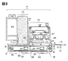
- FIG. 3 is an enlarged schematic view of a fixing unit (fixing device) of the image forming apparatus.
- Fig. 4 is a block diagram of the control system.
- FIG. 5 is a schematic cross-sectional view of an image formed by an ultraviolet-curable liquid developer.
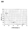
- FIG. 6 is a correlation diagram of the integrated light amount with respect to the developer temperature.
- FIG. 7 is a transition diagram of the transport belt temperature when the suction fan is provided (ON) or not (OFF).
- FIG. 8 is a flowchart of the standby operation of the fixing unit according to the second embodiment.
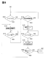
- FIG. 9 is a flowchart of suction fan control in the third embodiment.
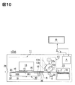
- FIG. 10 is a schematic vertical front view of the image forming apparatus according to the fourth embodiment.
- FIG. 11 is a flowchart (part 1) of the standby operation of the fixing unit in the fourth embodiment.
- FIG. 12 is a flowchart (part 2) of the standby operation of the fixing unit in the fourth embodiment.
- FIG. 2 is a schematic vertical front view of the image forming apparatus 100 according to the first embodiment.
- the front side (front side, front side) of the image forming apparatus 100 is the opposite side of the front side and the back side (rear side, back side) in the paper of FIG.
- the left and right are the left and right when the apparatus 100 is viewed from the front. Up and down are above and below in the direction of gravity.
- the upstream side and the downstream side are the upstream side and the downstream side in the recording material conveyance direction.
- ultraviolet light is referred to as UV or UV light
- IR or IR light infrared light
- the image forming apparatus 100 is a printer using a transfer type electrophotographic process. That is, the apparatus 100 performs an image forming operation (printing operation) based on an image forming job (print job) input (input) from a host device B such as a personal computer to a control unit (control circuit unit) A, and performs recording on the recording material 16. To form a toner image.
- the image forming job is an image forming instruction to which print condition information such as image data, information on the type of recording material to be used, the number of copies, the number of copies, and post-processing information is added.
- the control unit A controls all the devices of the device 100 and the sequence control of the image forming operation.
- C denotes an operation unit (user interface) of the image forming apparatus 100.
- the operation unit C includes a main power switch MSW, numeric keys and various buttons C1 for inputting various information to the control unit A, a display unit C2 such as a liquid crystal touch panel, and the like.
- Various information is displayed on the display unit C2 by the control unit A and the host device B.
- Various information can also be input to the control unit A from the display unit C2.
- the image forming unit 100 forms an unfixed image on a recording material using a liquid developer when a liquid carrier (ultraviolet curable liquid, ultraviolet curable agent) that is cured (ultraviolet curable) by toner and UV light is included. 10 is provided. Further, the apparatus 100 includes a fixing unit (fixing device) 11 for fixing the image 15 formed on the recording material 16 to the recording material 16.
- a liquid carrier ultraviolet curable liquid, ultraviolet curable agent
- the recording material 16 is a sheet-like recording medium (media) on which an image is formed by the image forming apparatus 100, and may be, for example, plain paper, coated paper, a postcard or envelope, an OHP sheet, or a resin film. Hereinafter, the recording material is also referred to as paper or paper.
- the sheets 16 are stored in a sheet cassette 25 in a bundle.
- the paper 16 in the paper feed cassette 25 is separated into one by the paper feed mechanism 2, and is fed to the image forming unit 10 via the transport path 26.
- the paper feed cassettes 25 may be arranged in a plurality of stages, and sheets having different materials and sizes of the paper 16 may be arranged in the image forming apparatus 100 in advance.
- the image forming unit 10 has the cylindrical photosensitive drum 1 as an image carrier. Further, the image forming unit 10 includes an electrophotographic image forming unit (process device) disposed around the photosensitive drum 1. Specifically, a charging section 10a for uniformly charging the surface of the photosensitive drum 1, an exposure section 10b for forming an electrostatic latent image by exposure, and a development for developing the electrostatic latent image with the liquid developer described above. The section 10c, the transfer roller 4, and a cleaner section 10d for removing unnecessary liquid developer.
- a charging section 10a for uniformly charging the surface of the photosensitive drum 1
- an exposure section 10b for forming an electrostatic latent image by exposure
- a development for developing the electrostatic latent image with the liquid developer described above.
- the section 10c, the transfer roller 4, and a cleaner section 10d for removing unnecessary liquid developer.
- the photosensitive drum 1 in the present embodiment is an aluminum cylinder having a thickness of 3 mm and an outer diameter of 84 mm, has an organic photosensitive member surface layer on the surface, and has a longitudinal width (length in a direction substantially orthogonal to the paper conveying direction) of 370 mm. .
- the transfer roller 4 is a roller composed of two types of materials in which a core metal is formed by winding urethane rubber around a metal shaft obtained by subjecting a SUM material to KN plating.
- the photosensitive drum 1 is arranged so as to be pressed and contacted by a pressing mechanism (not shown) to form a nip (transfer nip).
- the photosensitive drum 1 is driven by a drive motor M1 (main motor: FIG. 4), which is a drive unit controlled by the control unit A, at a predetermined peripheral speed in the direction of arrow R1 in FIG. (Process speed).
- the transfer roller 4 is also driven to rotate at the nip by the drive motor M1 in the direction of the arrow R2, which is the same as the rotation direction of the photosensitive drum 1.
- the paper 16 sent out from the paper feed cassette 25 is formed on the photosensitive drum 1 by the nip formed by the photosensitive drum 1 and the transfer roller 4 so as to synchronize with the toner image (image of the liquid developer) developed by the developing unit 10c. Is controlled to enter.
- the toner image developed on the photosensitive drum 1 is sequentially transferred to an arbitrary position on the paper 16 while the paper 16 is being nipped and conveyed by the transfer nip. That is, the unfixed image 15 of the liquid developer is transferred and formed on the paper 16 (on the recording material).
- the sheet 16 on which the image 15 has been formed by the image forming unit 10 is conveyed to the fixing unit 11 through the conveying path 27.
- # 51 denotes a jam detection sensor (recording material sensor) provided in the transport path 27.
- the sensor 51 is disposed on a transport path (recording material transport path) 27 on the upstream side in the paper transport direction (upstream on the recording material transport direction) with respect to the paper transport apparatus (recording material transport mechanism) 30 in the fixing unit 11 described later. I have.
- the sensor 51 When the paper 16 is not present at the position of the sensor 51, the sensor 51 outputs an off signal, and when the paper 16 is present, the sensor 51 outputs an on signal, and the off signal and the on signal are controlled. Input to Part A.
- the control unit A determines that a paper jam has occurred if the ON signal or the OFF signal input from the sensor 51 is longer or shorter than a specified time on the sequence after the paper feed from the paper feed cassette 25 is started. I do.
- control unit A detects whether or not the sheet 16 has been fed at the correct timing and has passed through the image forming unit 10 by switching between the ON signal and the OFF signal of the sensor 51 accompanying the sheet conveyance.
- the control unit A determines that the sheet 16 cannot be conveyed at the correct timing if the sensor 51 does not turn on even if a predetermined time has elapsed after the start of sheet feeding, or if the ON signal of the sensor 51 continues for a predetermined time or more. I do.
- the control unit A urgently stops the image forming operation of the image forming apparatus 100 as a jam has occurred, and displays on the operation unit C and the display unit of the host device B a message urging the user to perform the jam processing.
- the image forming unit 10 has the configuration of the electrophotographic type-direct transfer type, but the image forming method on the paper 16 is not limited to this.
- an intermediate transfer system using the photosensitive drum 1 as an intermediate transfer belt may be used.
- an image formed by the image forming means on the photosensitive drum using a liquid developer is primarily transferred by a primary transfer roller to an intermediate transfer member, and the transfer means 4 is a secondary transfer roller and is formed on the intermediate transfer member. Is transferred to the paper 16.
- the fixing unit 11 includes an IR irradiator (infrared irradiator) 13 that irradiates the paper 16 with IR light, a UV irradiator (ultraviolet irradiator) 12 that irradiates the paper 16 with UV light, and a paper transport that transports the paper 16.
- An apparatus (recording material transport mechanism) 30 is included.
- the device In the process of passing under the IR irradiating device 13, the device is irradiated with IR light and heated to raise its own temperature to a predetermined temperature. Irradiated.
- the unfixed image 15 of the liquid developer on the sheet is fixed by UV curing as a fixed image.
- UV-curable liquid developer used in the first embodiment and the mechanism related to its curing will be briefly described.
- FIG. 5 is a schematic cross-sectional view of the unfixed image 15 formed on the paper 16 by the UV-curable liquid developer.
- a toner 22 is dispersed in a liquid carrier (ultraviolet curing agent) 21 which is cured by UV light.
- the liquid carrier 21 is composed of at least monomers of a photopolymerizing agent and an ultraviolet curing agent.
- the toner 22 includes a toner resin 23 which is a base of the toner 22 and a colorant 24.
- the photopolymerization initiator excited by the UV light emits an acid, the generated acid and the monomer start a polymerization reaction, and the liquid carrier 21 starts to harden. Things. Therefore, the fixing of the unfixed image 15 by the UV-curable liquid developer is performed by curing the liquid carrier 21 on the sheet 16 by irradiating the UV light and fixing the liquid carrier 21 and the toner 22 on the sheet 16. Done.
- the paper 16 subjected to the fixing process in the fixing unit 11 is discharged to the outside of the apparatus by a discharge unit (not shown) as an image formed product (product) through a discharge conveyance path 28, or a finisher unit (not shown).
- the finisher unit is a post-processing unit that performs various types of finisher processing, such as stable processing, punching processing, and bookbinding processing, on the paper 16 on which the fixing processing has been performed. (Detailed configuration of fixing unit)
- FIG. 3 is an enlarged schematic diagram of a fixing unit (fixing device) 11 in the image forming apparatus 100 of FIG.
- the fixing unit 11 is roughly classified into three units: an IR irradiator 13, a UV irradiator 12, and a paper transport device (recording material transport mechanism) 30.
- unfixed image 15 formed of the liquid developer is formed on the upper surface, and sheet 16 conveyed from image forming unit 10 enters fixing unit 11 from arrow X1.
- the paper transporting device 30 is a unit that transports the paper 16 that has entered the fixing unit 11 in the direction of arrow Y1 and delivers it to the above-described discharge unit (not shown) or the finisher unit (not shown).
- the paper transport device 30 is provided with an endless transport belt (an endless rotatable belt having air permeability, a perforated belt: hereinafter referred to as a belt) 31 provided with a number of holes. Further, the sheet transporting device 30 includes a driving roller 35 and driven rollers 36, 37, and 38 as a belt stretching member (belt supporting roller) that stretches the belt 31 rotatably. Further, the paper transport device 30 includes a transport drive motor M2 (FIG. 4) for rotating the belt 31 via the drive roller 35.
- a transport drive motor M2 FIG. 4
- the belt 31 is rotated at a predetermined peripheral speed (process speed) in the direction of the arrow R3 by driving the transport drive motor M2.
- the belt 31 according to the first embodiment has a width of 350 mm, a circumference of 900 mm, and a PI resin.
- the belt 31 rotates at a peripheral speed of 785 mm / s.
- the air suction unit 300 for sucking and holding the paper 16 on the belt 31 is disposed inside the belt 31.
- the air suction unit 300 includes a perforated plate (hole) as a flat belt supporting plate (suction plate) having air permeability for supporting the inner surface of the ascending side belt portion (belt portion on the recording material conveying side) of the belt 31 on the upper surface. (A perforated plate) 301. Further, the air suction unit 300 has a suction chamber 302 made of a heat-resistant resin (PPS resin in this embodiment) fixed and arranged on the lower surface side of the plate 301 so as to be in close contact with the plate 301.
- PPS resin heat-resistant resin
- suction chambers 302 There are two suction chambers 302, and a duct 303 through which air passes is connected to each of the chambers 302, and an air suction fan 304 controlled by the control unit A is attached to the front of the duct 303.
- the inner surface of the belt portion on the ascending side of the belt 31 is slidably supported on the upper surface of the plate 301. When the belt 31 is driven to rotate, the inner surface of the belt 31 slides (slids) while being in contact with the upper surface of the plate 301.
- the air suction unit 300 applies a negative pressure for sucking and holding the paper 16 on the belt 31 via the perforated plate 301 and the perforated belt 31. That is, when the suction fan 304 is moved (turned on), air is sucked in on the entire upper surface side of the perforated belt 31 and always forms an air flow in the depth direction of the paper surface of FIG. Thus, an air flow of the sheet transport device 30 is formed.
- the sheet 16 on which the unfixed image 15 is loaded comes from the image forming unit 10 side onto the belt 31, the side (back side) of the sheet 16 where the unfixed image 15 does not exist on the upper surface of the belt 31 is placed on the belt 31. It is conveyed in the direction of arrow Y1 by the belt 31 that is attracted and rotates.
- the sheet 16 on which the unfixed image 15 is formed by the image forming unit 10 sequentially passes under the IR irradiating device 13 and the UV irradiating device 12 which are arranged to face the belt portion on the ascending side of the belt 31. Pass through.
- heating of the sheet 16 by irradiation with IR light preliminary heating: image heating
- image fixing by irradiation of UV light are performed. That is, fixing is performed without contacting the surface of the unfixed image 15 without forming a fixing nip.
- the above-described paper transporting device 30 transports the paper 16 to the unfixed image 15 without a contact object such as a fixing roller or a fixing belt.
- the paper 16 on which the unfixed image 15 is placed follows the flat plate-shaped perforated plate 301 supporting the belt 31, and is transported in a substantially planar state.
- the unfixed image 15 is heated and UV-cured and fixed by the IR irradiating device 13 and the UV irradiating device 12 in the flat state of the sheet 16, and the fixing is completed in a state where the curl of the sheet 16 is suppressed. . That is, the flat plate 301 with holes suppresses deformation such as curling of the paper 16 due to the fixing operation.
- the flat plate-shaped perforated plate 301 that supports the inner surface of the belt is provided inside the belt portion that transports the paper 16 while sucking the air in the paper transport device 30. Therefore, when the unfixed toner is fixed on the sheet, the sheet is held in a straight state (flat state) following the belt 31, that is, the flat plate 301, and the fixing is completed. Therefore, the paper 16 is prevented from being deformed such as curl at the time of fixing an image, and the paper 16 is surely transferred to the pair of rollers on the downstream side of the paper transport device 30.
- the paper transport device 30 holds the paper 16 on which the image 15 is formed by the image forming unit 10 on a belt 31 by air suction, and the paper 16 is placed under the IR irradiation device 13 and the UV irradiation device 12.
- the paper 16 is conveyed so as to sequentially pass through. That is, the IR irradiator 13 and the UV irradiator 12 are arranged immediately above the belt portion on the ascending side of the belt 31 so as to face the belt and to be adjacent to the upstream side and the downstream side in the paper transport direction.
- the image 15 of the liquid developer on the paper 16 carried and conveyed on the belt 31 is first heated by being irradiated with the IR light by the IR irradiating device 13, and then is irradiated with the UV light by the UV irradiating device 12. Received and established.
- the fixing device according to the present embodiment is a fixing device that is not pressurized at the IR irradiation position and the UV irradiation position.
- the UV irradiation position refers to a position at which the maximum illuminance (peak illuminance) by the UV irradiating device 12 is observed as viewed from the position distribution in the sheet conveyance direction.
- the IR irradiation position refers to a position that is the center of an area having an illuminance of 90% or more of the peak illuminance of the IR irradiating device 13 when viewed in the position distribution in the sheet conveyance direction. (Configuration of IR irradiation device)
- the ⁇ IR irradiator 13 emits a far-infrared electromagnetic wave whose light source has a wavelength of 1 to 15 ⁇ m. Since the chemical bond in the organic substance has an absorption characteristic in the far-infrared region, the organic substance such as the liquid developer containing the toner used in the present embodiment can be efficiently heated by irradiating the far-infrared ray.
- a quartz tube 305 having a diameter of 17 mm and a length of 450 mm is employed as an object (infrared radiation member) that emits far-infrared rays.
- the center position of the quartz tube 305 is located at a height of 80 mm from the belt 31. Then, the temperature of the sheet 16 on which the unfixed image 15 is placed is raised without contact.
- a filament 306 made of a nichrome wire is arranged in the quartz tube 305.
- the filament 306 is heated and emits far-infrared rays through the quartz tube 305.
- An aluminum reflector 307 is disposed so as to cover the quartz tube 305 so that far infrared rays emitted from the quartz tube 305 can be efficiently emitted to the paper 16.
- the UV irradiation device 12 is disposed immediately downstream of the IR irradiation device 13 (downstream of the recording material conveyance direction).
- the UV irradiation device 12 uses an LED that emits UV light.
- An important item in the UV curing reaction is that "optical science changes are caused only by absorbed light out of the projected light amount”. That is, in UV curing, it is important that the absorption wavelength of the photopolymerization initiator and the emission wavelength of the UV light match.
- an LED having an illuminance peak wavelength of 385 ⁇ 5 ⁇ m and an illuminance peak of 1.8 W is used.
- the UV irradiation device 12 is provided with a cooling duct 309 and a blower fan (not shown) for preventing the temperature of the UV irradiation device 12 itself from rising. (Effect of heating by IR irradiation) Next, the effect of heating the unfixed image 15 by irradiating it with IR light before UV irradiation in the UV curing process of the liquid developer will be described.
- FIG. 6 shows the relationship between the surface temperature of the liquid developer in the unfixed image 15 and the integrated amount of UV light (mJ / cm 2 ) necessary for curing.
- the integrated light amount (mJ / cm 2 ) of the UV light required for curing decreases.
- the integrated amount of UV light is 590 mJ / cm 2 .
- the integrated amount of UV light is 118 mJ / cm 2 .
- 23 ° C. is assumed to be the environment in which the image forming apparatus 100 is installed and the temperature of the paper 16. Further, the thickness of the unfixed toner image formed on the paper 16 is only a few ⁇ m, and its temperature is considered to be almost the same as the temperature of the paper 16.
- the power consumption when the liquid developer is cured only by the UV irradiation device 12 at the temperature of the paper 16 of 23 ° C. is 14000 W.
- the control unit A sets the image forming unit 10 and the fixing unit 11 in a copyable state (a state in which an image forming operation is possible). ) To start standby operation.
- the standby operation is also called an adjustment operation, a start-up operation, and a warm-up operation.
- FIG. 1 shows a flowchart (standby operation sequence) of the standby operation of the fixing unit 11 in the first embodiment.
- the description of the standby operation of the image forming unit 10 is omitted for convenience.
- the control unit A drives the conveyance drive motor M2 of the sheet conveyance device 30 in the fixing unit 11 to drive the belt 31 via the drive roller 35. Is started (S2).
- the control unit A checks the rotation of the belt 31 with a rotation detection sensor (not shown). If the rotation detection sensor cannot detect the rotation of the belt 31, the control unit A determines that the device is abnormal, displays an error on the display unit C2 of the operation unit C, and stops the operation of the device 100 (S8).
- the UV light is irradiated from the UV irradiation device 12 while the belt 31 is stopped, only the belt portion immediately below the UV irradiation device 12 is irradiated with UV light, and the belt 31 may be damaged. Therefore, it is necessary to start the UV irradiation after the belt 31 rotates.
- the control unit A starts energizing the filament 306 in the IR irradiation device 13 and starts the temperature (surface) of the quartz tube (infrared radiation member) 305. Temperature) to start irradiation of IR light (S4).
- the control unit A checks the IR irradiation state of the IR irradiation device 13 with a state detection sensor (not shown).
- the control unit A determines that the apparatus is abnormal when the IR irradiation is not performed or there is an abnormality in the amount of IR irradiation by the confirmation by the state detection sensor, and displays an error on the display unit C2 of the operation unit C and The operation of the device 100 is stopped (S10).
- the temperature of the quartz tube 305 serving as the infrared radiation member reaches a predetermined temperature, specifically, about 830 ° C. on the surface. Need to be. However, it is difficult to directly detect the temperature with a sensor.
- the control unit A sets the surface temperature of the belt 31 to a predetermined heating temperature (standby completion temperature) within a predetermined time from the start of energization of the IR irradiation device 13 (start of energization of the filament 306). Is reached by the temperature sensor 308.
- the predetermined heating temperature of the belt 31 is set to 50 ° C.
- the controller A determines that the surface of the quartz tube 305 has reached the above-mentioned about 830 ° C. when the temperature sensor 308 detects the belt temperature of 50 ° C. (S5). When the temperature sensor 308 does not detect the belt temperature of 50 ° C. within the above-described predetermined time, the control unit A determines that the apparatus is abnormal, displays an error on the display unit C2 of the operation unit C, and operates the apparatus 100. Is stopped (S11).
- step S5 When the temperature sensor 308 detects the belt temperature of 50 ° C. in step S5, the control unit A turns on the suction fan 304 of the air suction system 300 for sucking the paper 16 on the belt 31 of the paper transport device 30. (S6).
- the control unit A checks the rotation of the suction fan 304 with a rotation detection sensor (not shown). If the rotation detection sensor cannot detect the rotation of the suction fan 304, it is determined that the apparatus is abnormal, an error is displayed on the display unit C2 of the operation unit C, and the operation of the apparatus 100 is stopped (S12).
- control unit A determines that the standby operation of the entire image forming apparatus is completed, together with the confirmation of the completion of the standby operation of the image forming unit 10. Then, the control section A displays a message indicating that the copy operation is OK on the display section C2 of the operation section C and enables the job to be accepted (S7).
- control unit A controls the power supplied to the IR irradiation device 13 based on the surface temperature detection information of the belt 31 input from the temperature sensor 308 so that the surface temperature of the belt 31 is maintained at 50 ° C.
- the feature of the above operation flow is that in the standby operation after the power of the apparatus 100 is turned on, the air suction operation of the air suction unit 300 is performed after the temperature of the quartz tube 305 of the IR irradiation device 13 in the fixing unit 11 reaches a predetermined temperature. Start (suction fan 304: ON).
- a temperature sensor 308 for detecting the surface temperature of the belt 31 is provided, and the surface temperature of the belt 31 is set to a predetermined heating temperature (in this embodiment, within a predetermined time from the start of energization to the IR irradiation device 13). (50 ° C.) is monitored by the temperature sensor 308.
- a predetermined heating temperature in this embodiment, within a predetermined time from the start of energization to the IR irradiation device 13. (50 ° C.) is monitored by the temperature sensor 308.
- the reason why the suction fan 304 is turned on after the temperature of the quartz tube 305 of the IR irradiation device 13 reaches a predetermined temperature (in this embodiment, the surface temperature of the belt 31 is 50 ° C.) during the standby operation is illustrated. 7 will be described.
- the vertical axis represents the surface temperature (° C.) of the belt 31 and the horizontal axis represents the elapsed time (minutes).
- the air suction unit 300 (suction fan 304) is not operated until the infrared radiation member 305 of the IR irradiation apparatus 13 reaches a predetermined temperature, so that IR irradiation is performed.
- the device 13 has no unnecessary airflow action. Therefore, there is an effect that the temperature rising time for heating the paper of the IR irradiation device 13 is shortened.
- the control unit A turns on the IR irradiation device 13 in response to the power of the device 100 being turned on, and the temperature of the infrared radiation member 305 of the IR irradiation device 13 becomes a predetermined temperature. , The air suction operation of the air suction unit 300 is started.
- the start of the air suction operation of the air suction unit 300 does not need to be in the standby state. That is, the suction may be started after a print command is input. There is almost no time lag from the start of suction until the inside of the belt transport mechanism becomes a negative pressure, so it is sufficient to start suction after a print command is input.
- FIG. 8 is a flowchart illustrating the standby operation of the fixing unit 11 according to the second embodiment.
- step S5 of detecting the belt temperature in the flowchart of FIG. 1 is changed to the next step S5A in comparison with the flowchart of FIG. 1 of the first embodiment.
- Steps other than the step S5A are the same as those in the flowchart of FIG.
- Step S5A in the second embodiment is a step in which it is determined whether or not a predetermined time has elapsed from the start of energization to the IR irradiating device 13, that is, the infrared irradiation: ON in step S4.
- the predetermined time here is a time from the start of energization to the IR irradiator 13 until the temperature of the quartz tube 305 serving as the infrared radiation member reaches the predetermined temperature (about 830 ° C. at the surface in the present embodiment) without error. , Which is a time obtained by actual measurement in advance.
- the controller A measures the temperature of the quartz tube 305 of the IR irradiator 13 at the predetermined time after the predetermined time elapses in step S5A without measuring the temperature of the belt 31. I judge. Then, the suction fan 304 of the air suction unit 300 for sucking the paper 16 on the belt 31 of the paper transport device 30 is turned on (S6).
- the control unit A checks the rotation of the suction fan 304 with a rotation detection sensor (not shown). If the rotation detection sensor cannot detect the rotation of the suction fan 304, it is determined that the apparatus is abnormal, an error is displayed on the display unit C2 of the operation unit C, and the operation of the apparatus 100 is stopped (S12).
- the reason why the suction fan 304 is turned on after the temperature of the quartz tube 305 of the IR irradiation device 13 reaches a predetermined temperature during the standby operation is the same as the standby operation in FIG. 1 of the first embodiment. . Also, as in the first embodiment, the IR irradiation of the IR irradiation device 13 is started from the standby state, but the start of the air suction operation of the air suction unit 300 does not need to be in the standby state. That is, the suction may be started after a print command is input.
- FIG. 9 shows a control sequence of the suction fan 304 of the fixing unit 11 after step S7 of FIG. 1 of the first embodiment and FIG. 8 of the second embodiment.
- control unit A waits for an input of an image forming job for a predetermined time (S13, S16).
- control unit A executes the image forming operation of the input job until the job ends (S14, S15).
- the control unit A stops the air suction operation of the air suction unit 300 in the fixing unit 11 in waiting for the input of the image forming job in step S13 or after a predetermined time has elapsed from the end of the job in step S15 (suction fan 304). : Off) (S17). Then, in this state, input of an image forming job is waited (S18).
- the control unit A uses the recording material detection signal from the recording material sensor 51 of the first sheet 16 of the input image forming job (S19: ON signal output) ), The air suction operation of the air suction unit 300 is started (S20). That is, the suction fan 304 is turned on.
- control unit A checks the rotation of the suction fan 304 by using a rotation detection sensor (not shown). If the rotation detection sensor cannot detect the rotation of the suction fan 304, it is determined that the apparatus is abnormal, an error is displayed on the display section C2 of the operation section C, and the operation of the apparatus 100 is stopped (S21).
- the control unit A executes the image forming operation of the input image forming job with the suction fan 304 turned on in step S20 (S14).
- a feature of the operation flow of FIG. 9 is that the control unit A controls the air suction unit based on a detection signal from the sensor 51 of the first sheet of a job input in a state where the air suction operation of the air suction unit 300 is stopped. This is to start the air suction operation of 300 (S17 to S20). That is, the trigger for switching the suction fan 304 from off to on is performed when the paper 16 turns on the sensor 51.
- the air suction operation of the air suction unit 300 is stopped while waiting for a job input (S16 to S18). Therefore, since there is no drive power for the suction fan 304 and unnecessary air flow in the IR irradiator 13 during that time, the power for controlling the temperature of the belt 31 by the IR irradiator 13 is reduced.
- the image forming apparatus 100 is an image forming apparatus that performs UV curing and fixing using a liquid developer.
- an IR irradiation device 13 and a UV irradiation device 12 are arranged in the fixing unit 11.
- the fixing unit 11 has no UV irradiation device 12 and has an IR irradiation device. It has only 13.
- FIGS. 11 and 12 are flowcharts of the standby operation of the fixing unit 11 in a case where the fixing unit 11 has only the IR irradiation device 13 without the UV irradiation device 12, respectively.
- FIG. 11 corresponds to the flowchart of FIG. 1 of the first embodiment
- FIG. 12 corresponds to the flowchart of FIG. 8 of the second embodiment. Steps S3 and S9 relating to control of the UV irradiation device 12 are omitted, respectively. ing.
- the control sequence of the suction fan 304 of the fixing unit 11 after step S7 is the same as that of FIG. 9 of the third embodiment.
- an image forming apparatus having a reduced standby time is provided.
Landscapes
- Physics & Mathematics (AREA)
- General Physics & Mathematics (AREA)
- Fixing For Electrophotography (AREA)
Priority Applications (1)
| Application Number | Priority Date | Filing Date | Title |
|---|---|---|---|
| US17/126,641 US11422490B2 (en) | 2018-06-21 | 2020-12-18 | Image forming apparatus with controlled operation for air suction |
Applications Claiming Priority (2)
| Application Number | Priority Date | Filing Date | Title |
|---|---|---|---|
| JP2018117841A JP7102247B2 (ja) | 2018-06-21 | 2018-06-21 | 画像形成装置 |
| JP2018-117841 | 2018-06-21 |
Related Child Applications (1)
| Application Number | Title | Priority Date | Filing Date |
|---|---|---|---|
| US17/126,641 Continuation US11422490B2 (en) | 2018-06-21 | 2020-12-18 | Image forming apparatus with controlled operation for air suction |
Publications (1)
| Publication Number | Publication Date |
|---|---|
| WO2019245057A1 true WO2019245057A1 (ja) | 2019-12-26 |
Family
ID=68983682
Family Applications (1)
| Application Number | Title | Priority Date | Filing Date |
|---|---|---|---|
| PCT/JP2019/025263 Ceased WO2019245057A1 (ja) | 2018-06-21 | 2019-06-19 | 画像形成装置 |
Country Status (3)
| Country | Link |
|---|---|
| US (1) | US11422490B2 (https=) |
| JP (1) | JP7102247B2 (https=) |
| WO (1) | WO2019245057A1 (https=) |
Families Citing this family (1)
| Publication number | Priority date | Publication date | Assignee | Title |
|---|---|---|---|---|
| JP2020166081A (ja) | 2019-03-29 | 2020-10-08 | キヤノン株式会社 | 定着装置 |
Citations (7)
| Publication number | Priority date | Publication date | Assignee | Title |
|---|---|---|---|---|
| US4412738A (en) * | 1980-04-21 | 1983-11-01 | Eastman Kodak Company | Vacuum document feeder |
| JP2001305937A (ja) * | 2000-04-21 | 2001-11-02 | Murata Mach Ltd | 画像形成装置 |
| JP2007307738A (ja) * | 2006-05-16 | 2007-11-29 | Tohoku Ricoh Co Ltd | 印刷物定着用紫外線照射装置 |
| JP2010096953A (ja) * | 2008-10-16 | 2010-04-30 | Canon Inc | 画像形成装置 |
| JP2014166918A (ja) * | 2013-01-29 | 2014-09-11 | Kyocera Document Solutions Inc | 用紙搬送装置及び該用紙搬送装置を備えた画像形成装置 |
| JP2017120377A (ja) * | 2015-12-24 | 2017-07-06 | キヤノン株式会社 | 画像形成装置 |
| JP2017187739A (ja) * | 2016-03-31 | 2017-10-12 | キヤノン株式会社 | 画像形成装置 |
Family Cites Families (14)
| Publication number | Priority date | Publication date | Assignee | Title |
|---|---|---|---|---|
| JP4354053B2 (ja) * | 1999-09-09 | 2009-10-28 | 東北リコー株式会社 | 印刷装置及び乾燥装置 |
| JP2007029582A (ja) | 2005-07-29 | 2007-02-08 | Konami Gaming Inc | ゲーム装置 |
| JP4994626B2 (ja) | 2005-09-13 | 2012-08-08 | キヤノン株式会社 | 画像加熱装置、及び画像形成装置 |
| JP5031213B2 (ja) | 2005-09-13 | 2012-09-19 | キヤノン株式会社 | 画像加熱装置、及び画像形成装置 |
| US7480480B2 (en) | 2005-09-13 | 2009-01-20 | Canon Kabushiki Kaisha | Image heating apparatus with heat pipe for decreasing unevenness in temperature distribution |
| JP5038949B2 (ja) | 2008-03-14 | 2012-10-03 | 三菱電機株式会社 | 表示装置 |
| JP4508254B2 (ja) | 2008-03-14 | 2010-07-21 | 富士ゼロックス株式会社 | 正帯電二成分現像剤、画像形成方法及び画像形成装置 |
| JP5863385B2 (ja) | 2011-10-26 | 2016-02-16 | キヤノン株式会社 | 画像加熱装置 |
| JP5818775B2 (ja) | 2012-12-06 | 2015-11-18 | キヤノン株式会社 | 画像形成装置 |
| JP2015034971A (ja) | 2013-07-12 | 2015-02-19 | キヤノン株式会社 | 定着用ローラ、その製造方法、定着装置 |
| JP6598595B2 (ja) | 2015-08-31 | 2019-10-30 | キヤノン株式会社 | 画像形成装置に着脱可能な画像加熱装置 |
| US9939760B2 (en) | 2015-12-24 | 2018-04-10 | Canon Kabushiki Kaisha | Image forming apparatus |
| JP6995519B2 (ja) | 2017-07-11 | 2022-01-14 | キヤノン株式会社 | 定着装置 |
| JP2020086193A (ja) | 2018-11-28 | 2020-06-04 | キヤノン株式会社 | 非接触加熱装置 |
-
2018
- 2018-06-21 JP JP2018117841A patent/JP7102247B2/ja not_active Expired - Fee Related
-
2019
- 2019-06-19 WO PCT/JP2019/025263 patent/WO2019245057A1/ja not_active Ceased
-
2020
- 2020-12-18 US US17/126,641 patent/US11422490B2/en active Active
Patent Citations (7)
| Publication number | Priority date | Publication date | Assignee | Title |
|---|---|---|---|---|
| US4412738A (en) * | 1980-04-21 | 1983-11-01 | Eastman Kodak Company | Vacuum document feeder |
| JP2001305937A (ja) * | 2000-04-21 | 2001-11-02 | Murata Mach Ltd | 画像形成装置 |
| JP2007307738A (ja) * | 2006-05-16 | 2007-11-29 | Tohoku Ricoh Co Ltd | 印刷物定着用紫外線照射装置 |
| JP2010096953A (ja) * | 2008-10-16 | 2010-04-30 | Canon Inc | 画像形成装置 |
| JP2014166918A (ja) * | 2013-01-29 | 2014-09-11 | Kyocera Document Solutions Inc | 用紙搬送装置及び該用紙搬送装置を備えた画像形成装置 |
| JP2017120377A (ja) * | 2015-12-24 | 2017-07-06 | キヤノン株式会社 | 画像形成装置 |
| JP2017187739A (ja) * | 2016-03-31 | 2017-10-12 | キヤノン株式会社 | 画像形成装置 |
Also Published As
| Publication number | Publication date |
|---|---|
| JP2019219558A (ja) | 2019-12-26 |
| JP7102247B2 (ja) | 2022-07-19 |
| US11422490B2 (en) | 2022-08-23 |
| US20210109466A1 (en) | 2021-04-15 |
Similar Documents
| Publication | Publication Date | Title |
|---|---|---|
| CN100472358C (zh) | 定影装置和图像形成设备 | |
| CN113272741B (zh) | 定影装置、图像形成装置 | |
| US10429761B2 (en) | Image forming apparatus using ultraviolet and infrared radiation | |
| CN106406056B (zh) | 定影装置 | |
| JP6060815B2 (ja) | 定着装置及び画像形成装置 | |
| US10969716B2 (en) | Non-contact image heating apparatus including a shielding member | |
| JP7102247B2 (ja) | 画像形成装置 | |
| JP5299848B2 (ja) | 定着装置および画像形成装置 | |
| JP7350514B2 (ja) | 画像形成装置 | |
| JP2010014804A (ja) | 定着システム及び画像形成装置 | |
| CN113302562A (zh) | 图像形成装置 | |
| JP2000305385A (ja) | 定着装置 | |
| WO2019240299A1 (ja) | 画像形成装置 | |
| JP5446810B2 (ja) | 定着装置及び画像形成装置 | |
| JP2008145903A (ja) | 定着装置及び画像形成装置 | |
| JP2022124727A (ja) | 画像形成装置 | |
| JP2011123293A (ja) | 定着装置及び画像形成装置 | |
| JP2020067467A (ja) | 画像形成装置 | |
| WO2017171099A1 (ja) | 画像形成装置 | |
| JP2016020944A (ja) | 定着装置および画像形成装置 | |
| JP2020071349A (ja) | 非接触加熱装置 | |
| JP2020034665A (ja) | 画像形成装置 | |
| JP2013044868A (ja) | 定着装置及び画像形成装置 | |
| JP2020071346A (ja) | 加熱定着装置および画像形成装置 | |
| JP2017120377A (ja) | 画像形成装置 |
Legal Events
| Date | Code | Title | Description |
|---|---|---|---|
| 121 | Ep: the epo has been informed by wipo that ep was designated in this application |
Ref document number: 19822919 Country of ref document: EP Kind code of ref document: A1 |
|
| NENP | Non-entry into the national phase |
Ref country code: DE |
|
| 122 | Ep: pct application non-entry in european phase |
Ref document number: 19822919 Country of ref document: EP Kind code of ref document: A1 |