WO2019245057A1 - Image forming device - Google Patents
Image forming device Download PDFInfo
- Publication number
- WO2019245057A1 WO2019245057A1 PCT/JP2019/025263 JP2019025263W WO2019245057A1 WO 2019245057 A1 WO2019245057 A1 WO 2019245057A1 JP 2019025263 W JP2019025263 W JP 2019025263W WO 2019245057 A1 WO2019245057 A1 WO 2019245057A1
- Authority
- WO
- WIPO (PCT)
- Prior art keywords
- belt
- recording material
- image forming
- unit
- temperature
- Prior art date
Links
Images


Classifications
-
- G—PHYSICS
- G03—PHOTOGRAPHY; CINEMATOGRAPHY; ANALOGOUS TECHNIQUES USING WAVES OTHER THAN OPTICAL WAVES; ELECTROGRAPHY; HOLOGRAPHY
- G03G—ELECTROGRAPHY; ELECTROPHOTOGRAPHY; MAGNETOGRAPHY
- G03G15/00—Apparatus for electrographic processes using a charge pattern
- G03G15/20—Apparatus for electrographic processes using a charge pattern for fixing, e.g. by using heat
- G03G15/2003—Apparatus for electrographic processes using a charge pattern for fixing, e.g. by using heat using heat
- G03G15/2014—Apparatus for electrographic processes using a charge pattern for fixing, e.g. by using heat using heat using contact heat
- G03G15/2017—Structural details of the fixing unit in general, e.g. cooling means, heat shielding means
- G03G15/2028—Structural details of the fixing unit in general, e.g. cooling means, heat shielding means with means for handling the copy material in the fixing nip, e.g. introduction guides, stripping means
-
- G—PHYSICS
- G03—PHOTOGRAPHY; CINEMATOGRAPHY; ANALOGOUS TECHNIQUES USING WAVES OTHER THAN OPTICAL WAVES; ELECTROGRAPHY; HOLOGRAPHY
- G03G—ELECTROGRAPHY; ELECTROPHOTOGRAPHY; MAGNETOGRAPHY
- G03G15/00—Apparatus for electrographic processes using a charge pattern
- G03G15/20—Apparatus for electrographic processes using a charge pattern for fixing, e.g. by using heat
- G03G15/2098—Apparatus for electrographic processes using a charge pattern for fixing, e.g. by using heat using light, e.g. UV photohardening
Definitions
- the present invention relates to an image forming apparatus provided with a fixing device provided with an infrared irradiating device for heating an unfixed image created in an image forming unit by infrared irradiation and assisting or fixing the image onto a recording material.
- a toner image created by an image forming unit is transferred to a recording material (hereinafter, also referred to as a sheet) by a transfer device, and a sheet on which the toner image is transferred is Is transported to the fixing device. Then, the sheet on which the unfixed toner image is placed passes between a fixing nip formed by a fixing member and a pressing member arranged in the fixing device.
- a fixing method in which heating and pressurization are performed simultaneously to fix the toner image on the sheet has been generally adopted.
- the fixing member and the pressing member mainly include a roller and a belt, and the heating member is often disposed inside the fixing member and the pressing member.
- an unfixed toner image is pressed against a fixing member by a pressing member, and heating and pressing of the toner are performed at the same time. Curl and wrinkles that may deform the paper itself may occur.
- the fixing temperature of the fixing member is set too high, the toner melts too much and the cohesive force between the toners is reduced, causing a problem of a high-temperature offset phenomenon in which the toner melts into the fixing member and is removed to the fixing member side.
- the temperature of the fixing member may increase in a portion of the fixing member where the sheet does not contact. This phenomenon is called a non-sheet passing portion temperature increase. Thereafter, when a sheet wider than the preceding sheet is passed, a high-temperature offset phenomenon may occur.
- Japanese Patent Application Laid-Open No. 2007-29582 discloses that although a sheet on which an unfixed toner image is transferred passes through a fixing nip composed of a fixing member and a pressing member, a heat source is not located inside the fixing member and the pressing member but upstream thereof. Is described. This is to solve the problem of fixing offset by separating the functions of heating and pressing.
- the heat source an infrared irradiation device capable of irradiating infrared light is used.
- Japanese Unexamined Patent Application Publication No. 2009-222896 describes an apparatus configuration that employs light irradiation fixing (flash fixing) in which a pressing member can fix a sheet on which an unfixed toner image is mounted in a non-contact manner.
- flash fixing light irradiation fixing
- This is in addition to the above-mentioned fixing hot offset problem, solving the curl and wrinkle problems of the paper itself after passing through the fixing device, and dealing with special paper such as seal materials and envelopes.
- the nip between the fixing member and the pressure member It is a proposal that focuses on impossible super-high-speed printing.
- Light irradiation uses a far-infrared irradiation device that can emit far-infrared rays.
- Japanese Patent Application No. 2017-7790 discloses an image forming apparatus which uses a liquid developer which is cured by ultraviolet rays for securing the fixing property and has an ultraviolet irradiation device for fixing the liquid developer on a recording material. Have been. This focuses on the problem that the fixing property cannot be sufficiently secured only by light irradiation fixing using infrared rays in order to further increase the speed.
- a liquid developer can be instantly cured by a fixing device using an ultraviolet irradiation device, and is used for drying a high-speed UV offset printing machine or a UV inkjet printing machine.
- infrared irradiation is performed.
- An apparatus or a fixing device combining an infrared irradiation apparatus and an ultraviolet irradiation apparatus needs to convey a recording material on which an unfixed image is placed to a fixing unit.
- a device using air suction and a device using electrostatic adsorption can be considered, but air suction is more effective. This is because the use of electrostatic means may disturb the unfixed toner image on the recording material.
- the infrared irradiator when air was used, there were the following problems. That is, the infrared irradiator must reach a certain temperature in order to exhibit its capabilities. However, the effect of cooling the infrared irradiating device is produced by performing the air suction in the recording material conveying unit, and the standby time (warm-up time) is prolonged, particularly during the standby operation (start-up) of the image forming apparatus. There were challenges.
- an image forming unit that forms an unfixed image on a recording material, an endless rotatable belt having air permeability, and a recording material disposed on a belt disposed inside the belt
- An air suction unit that applies a negative pressure for sucking and holding the recording material through the belt, and the recording material on which the unfixed image is formed by the image forming unit is suction-held on the belt and conveyed.
- a conveying mechanism an infrared irradiator for heating the image by irradiating the recording material conveyed while being sucked and held on the belt with an infrared ray irradiating unit, which is disposed to face a belt portion of the belt on the recording material conveying side, and A control unit for controlling the operation of the recording material transport mechanism and the infrared irradiation unit, wherein the control unit turns on the infrared irradiation unit in response to power-on of the image forming apparatus; Temperature of the infrared radiation member
- the image forming apparatus is provided in which after reaching the temperature the start of air suction operation of the air suction part.
- FIG. 1 is a flowchart of the standby operation of the fixing unit according to the first embodiment.
- FIG. 2 is a schematic vertical front view of the image forming apparatus according to the first embodiment.
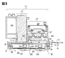
- FIG. 3 is an enlarged schematic view of a fixing unit (fixing device) of the image forming apparatus.
- Fig. 4 is a block diagram of the control system.
- FIG. 5 is a schematic cross-sectional view of an image formed by an ultraviolet-curable liquid developer.
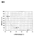
- FIG. 6 is a correlation diagram of the integrated light amount with respect to the developer temperature.
- FIG. 7 is a transition diagram of the transport belt temperature when the suction fan is provided (ON) or not (OFF).
- FIG. 8 is a flowchart of the standby operation of the fixing unit according to the second embodiment.
- FIG. 9 is a flowchart of suction fan control in the third embodiment.
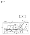
- FIG. 10 is a schematic vertical front view of the image forming apparatus according to the fourth embodiment.
- FIG. 11 is a flowchart (part 1) of the standby operation of the fixing unit in the fourth embodiment.
- FIG. 12 is a flowchart (part 2) of the standby operation of the fixing unit in the fourth embodiment.
- FIG. 2 is a schematic vertical front view of the image forming apparatus 100 according to the first embodiment.
- the front side (front side, front side) of the image forming apparatus 100 is the opposite side of the front side and the back side (rear side, back side) in the paper of FIG.
- the left and right are the left and right when the apparatus 100 is viewed from the front. Up and down are above and below in the direction of gravity.
- the upstream side and the downstream side are the upstream side and the downstream side in the recording material conveyance direction.
- ultraviolet light is referred to as UV or UV light
- IR or IR light infrared light
- the image forming apparatus 100 is a printer using a transfer type electrophotographic process. That is, the apparatus 100 performs an image forming operation (printing operation) based on an image forming job (print job) input (input) from a host device B such as a personal computer to a control unit (control circuit unit) A, and performs recording on the recording material 16. To form a toner image.
- the image forming job is an image forming instruction to which print condition information such as image data, information on the type of recording material to be used, the number of copies, the number of copies, and post-processing information is added.
- the control unit A controls all the devices of the device 100 and the sequence control of the image forming operation.
- C denotes an operation unit (user interface) of the image forming apparatus 100.
- the operation unit C includes a main power switch MSW, numeric keys and various buttons C1 for inputting various information to the control unit A, a display unit C2 such as a liquid crystal touch panel, and the like.
- Various information is displayed on the display unit C2 by the control unit A and the host device B.
- Various information can also be input to the control unit A from the display unit C2.
- the image forming unit 100 forms an unfixed image on a recording material using a liquid developer when a liquid carrier (ultraviolet curable liquid, ultraviolet curable agent) that is cured (ultraviolet curable) by toner and UV light is included. 10 is provided. Further, the apparatus 100 includes a fixing unit (fixing device) 11 for fixing the image 15 formed on the recording material 16 to the recording material 16.
- a liquid carrier ultraviolet curable liquid, ultraviolet curable agent
- the recording material 16 is a sheet-like recording medium (media) on which an image is formed by the image forming apparatus 100, and may be, for example, plain paper, coated paper, a postcard or envelope, an OHP sheet, or a resin film. Hereinafter, the recording material is also referred to as paper or paper.
- the sheets 16 are stored in a sheet cassette 25 in a bundle.
- the paper 16 in the paper feed cassette 25 is separated into one by the paper feed mechanism 2, and is fed to the image forming unit 10 via the transport path 26.
- the paper feed cassettes 25 may be arranged in a plurality of stages, and sheets having different materials and sizes of the paper 16 may be arranged in the image forming apparatus 100 in advance.
- the image forming unit 10 has the cylindrical photosensitive drum 1 as an image carrier. Further, the image forming unit 10 includes an electrophotographic image forming unit (process device) disposed around the photosensitive drum 1. Specifically, a charging section 10a for uniformly charging the surface of the photosensitive drum 1, an exposure section 10b for forming an electrostatic latent image by exposure, and a development for developing the electrostatic latent image with the liquid developer described above. The section 10c, the transfer roller 4, and a cleaner section 10d for removing unnecessary liquid developer.
- a charging section 10a for uniformly charging the surface of the photosensitive drum 1
- an exposure section 10b for forming an electrostatic latent image by exposure
- a development for developing the electrostatic latent image with the liquid developer described above.
- the section 10c, the transfer roller 4, and a cleaner section 10d for removing unnecessary liquid developer.
- the photosensitive drum 1 in the present embodiment is an aluminum cylinder having a thickness of 3 mm and an outer diameter of 84 mm, has an organic photosensitive member surface layer on the surface, and has a longitudinal width (length in a direction substantially orthogonal to the paper conveying direction) of 370 mm. .
- the transfer roller 4 is a roller composed of two types of materials in which a core metal is formed by winding urethane rubber around a metal shaft obtained by subjecting a SUM material to KN plating.
- the photosensitive drum 1 is arranged so as to be pressed and contacted by a pressing mechanism (not shown) to form a nip (transfer nip).
- the photosensitive drum 1 is driven by a drive motor M1 (main motor: FIG. 4), which is a drive unit controlled by the control unit A, at a predetermined peripheral speed in the direction of arrow R1 in FIG. (Process speed).
- the transfer roller 4 is also driven to rotate at the nip by the drive motor M1 in the direction of the arrow R2, which is the same as the rotation direction of the photosensitive drum 1.
- the paper 16 sent out from the paper feed cassette 25 is formed on the photosensitive drum 1 by the nip formed by the photosensitive drum 1 and the transfer roller 4 so as to synchronize with the toner image (image of the liquid developer) developed by the developing unit 10c. Is controlled to enter.
- the toner image developed on the photosensitive drum 1 is sequentially transferred to an arbitrary position on the paper 16 while the paper 16 is being nipped and conveyed by the transfer nip. That is, the unfixed image 15 of the liquid developer is transferred and formed on the paper 16 (on the recording material).
- the sheet 16 on which the image 15 has been formed by the image forming unit 10 is conveyed to the fixing unit 11 through the conveying path 27.
- # 51 denotes a jam detection sensor (recording material sensor) provided in the transport path 27.
- the sensor 51 is disposed on a transport path (recording material transport path) 27 on the upstream side in the paper transport direction (upstream on the recording material transport direction) with respect to the paper transport apparatus (recording material transport mechanism) 30 in the fixing unit 11 described later. I have.
- the sensor 51 When the paper 16 is not present at the position of the sensor 51, the sensor 51 outputs an off signal, and when the paper 16 is present, the sensor 51 outputs an on signal, and the off signal and the on signal are controlled. Input to Part A.
- the control unit A determines that a paper jam has occurred if the ON signal or the OFF signal input from the sensor 51 is longer or shorter than a specified time on the sequence after the paper feed from the paper feed cassette 25 is started. I do.
- control unit A detects whether or not the sheet 16 has been fed at the correct timing and has passed through the image forming unit 10 by switching between the ON signal and the OFF signal of the sensor 51 accompanying the sheet conveyance.
- the control unit A determines that the sheet 16 cannot be conveyed at the correct timing if the sensor 51 does not turn on even if a predetermined time has elapsed after the start of sheet feeding, or if the ON signal of the sensor 51 continues for a predetermined time or more. I do.
- the control unit A urgently stops the image forming operation of the image forming apparatus 100 as a jam has occurred, and displays on the operation unit C and the display unit of the host device B a message urging the user to perform the jam processing.
- the image forming unit 10 has the configuration of the electrophotographic type-direct transfer type, but the image forming method on the paper 16 is not limited to this.
- an intermediate transfer system using the photosensitive drum 1 as an intermediate transfer belt may be used.
- an image formed by the image forming means on the photosensitive drum using a liquid developer is primarily transferred by a primary transfer roller to an intermediate transfer member, and the transfer means 4 is a secondary transfer roller and is formed on the intermediate transfer member. Is transferred to the paper 16.
- the fixing unit 11 includes an IR irradiator (infrared irradiator) 13 that irradiates the paper 16 with IR light, a UV irradiator (ultraviolet irradiator) 12 that irradiates the paper 16 with UV light, and a paper transport that transports the paper 16.
- An apparatus (recording material transport mechanism) 30 is included.
- the device In the process of passing under the IR irradiating device 13, the device is irradiated with IR light and heated to raise its own temperature to a predetermined temperature. Irradiated.
- the unfixed image 15 of the liquid developer on the sheet is fixed by UV curing as a fixed image.
- UV-curable liquid developer used in the first embodiment and the mechanism related to its curing will be briefly described.
- FIG. 5 is a schematic cross-sectional view of the unfixed image 15 formed on the paper 16 by the UV-curable liquid developer.
- a toner 22 is dispersed in a liquid carrier (ultraviolet curing agent) 21 which is cured by UV light.
- the liquid carrier 21 is composed of at least monomers of a photopolymerizing agent and an ultraviolet curing agent.
- the toner 22 includes a toner resin 23 which is a base of the toner 22 and a colorant 24.
- the photopolymerization initiator excited by the UV light emits an acid, the generated acid and the monomer start a polymerization reaction, and the liquid carrier 21 starts to harden. Things. Therefore, the fixing of the unfixed image 15 by the UV-curable liquid developer is performed by curing the liquid carrier 21 on the sheet 16 by irradiating the UV light and fixing the liquid carrier 21 and the toner 22 on the sheet 16. Done.
- the paper 16 subjected to the fixing process in the fixing unit 11 is discharged to the outside of the apparatus by a discharge unit (not shown) as an image formed product (product) through a discharge conveyance path 28, or a finisher unit (not shown).
- the finisher unit is a post-processing unit that performs various types of finisher processing, such as stable processing, punching processing, and bookbinding processing, on the paper 16 on which the fixing processing has been performed. (Detailed configuration of fixing unit)
- FIG. 3 is an enlarged schematic diagram of a fixing unit (fixing device) 11 in the image forming apparatus 100 of FIG.
- the fixing unit 11 is roughly classified into three units: an IR irradiator 13, a UV irradiator 12, and a paper transport device (recording material transport mechanism) 30.
- unfixed image 15 formed of the liquid developer is formed on the upper surface, and sheet 16 conveyed from image forming unit 10 enters fixing unit 11 from arrow X1.
- the paper transporting device 30 is a unit that transports the paper 16 that has entered the fixing unit 11 in the direction of arrow Y1 and delivers it to the above-described discharge unit (not shown) or the finisher unit (not shown).
- the paper transport device 30 is provided with an endless transport belt (an endless rotatable belt having air permeability, a perforated belt: hereinafter referred to as a belt) 31 provided with a number of holes. Further, the sheet transporting device 30 includes a driving roller 35 and driven rollers 36, 37, and 38 as a belt stretching member (belt supporting roller) that stretches the belt 31 rotatably. Further, the paper transport device 30 includes a transport drive motor M2 (FIG. 4) for rotating the belt 31 via the drive roller 35.
- a transport drive motor M2 FIG. 4
- the belt 31 is rotated at a predetermined peripheral speed (process speed) in the direction of the arrow R3 by driving the transport drive motor M2.
- the belt 31 according to the first embodiment has a width of 350 mm, a circumference of 900 mm, and a PI resin.
- the belt 31 rotates at a peripheral speed of 785 mm / s.
- the air suction unit 300 for sucking and holding the paper 16 on the belt 31 is disposed inside the belt 31.
- the air suction unit 300 includes a perforated plate (hole) as a flat belt supporting plate (suction plate) having air permeability for supporting the inner surface of the ascending side belt portion (belt portion on the recording material conveying side) of the belt 31 on the upper surface. (A perforated plate) 301. Further, the air suction unit 300 has a suction chamber 302 made of a heat-resistant resin (PPS resin in this embodiment) fixed and arranged on the lower surface side of the plate 301 so as to be in close contact with the plate 301.
- PPS resin heat-resistant resin
- suction chambers 302 There are two suction chambers 302, and a duct 303 through which air passes is connected to each of the chambers 302, and an air suction fan 304 controlled by the control unit A is attached to the front of the duct 303.
- the inner surface of the belt portion on the ascending side of the belt 31 is slidably supported on the upper surface of the plate 301. When the belt 31 is driven to rotate, the inner surface of the belt 31 slides (slids) while being in contact with the upper surface of the plate 301.
- the air suction unit 300 applies a negative pressure for sucking and holding the paper 16 on the belt 31 via the perforated plate 301 and the perforated belt 31. That is, when the suction fan 304 is moved (turned on), air is sucked in on the entire upper surface side of the perforated belt 31 and always forms an air flow in the depth direction of the paper surface of FIG. Thus, an air flow of the sheet transport device 30 is formed.
- the sheet 16 on which the unfixed image 15 is loaded comes from the image forming unit 10 side onto the belt 31, the side (back side) of the sheet 16 where the unfixed image 15 does not exist on the upper surface of the belt 31 is placed on the belt 31. It is conveyed in the direction of arrow Y1 by the belt 31 that is attracted and rotates.
- the sheet 16 on which the unfixed image 15 is formed by the image forming unit 10 sequentially passes under the IR irradiating device 13 and the UV irradiating device 12 which are arranged to face the belt portion on the ascending side of the belt 31. Pass through.
- heating of the sheet 16 by irradiation with IR light preliminary heating: image heating
- image fixing by irradiation of UV light are performed. That is, fixing is performed without contacting the surface of the unfixed image 15 without forming a fixing nip.
- the above-described paper transporting device 30 transports the paper 16 to the unfixed image 15 without a contact object such as a fixing roller or a fixing belt.
- the paper 16 on which the unfixed image 15 is placed follows the flat plate-shaped perforated plate 301 supporting the belt 31, and is transported in a substantially planar state.
- the unfixed image 15 is heated and UV-cured and fixed by the IR irradiating device 13 and the UV irradiating device 12 in the flat state of the sheet 16, and the fixing is completed in a state where the curl of the sheet 16 is suppressed. . That is, the flat plate 301 with holes suppresses deformation such as curling of the paper 16 due to the fixing operation.
- the flat plate-shaped perforated plate 301 that supports the inner surface of the belt is provided inside the belt portion that transports the paper 16 while sucking the air in the paper transport device 30. Therefore, when the unfixed toner is fixed on the sheet, the sheet is held in a straight state (flat state) following the belt 31, that is, the flat plate 301, and the fixing is completed. Therefore, the paper 16 is prevented from being deformed such as curl at the time of fixing an image, and the paper 16 is surely transferred to the pair of rollers on the downstream side of the paper transport device 30.
- the paper transport device 30 holds the paper 16 on which the image 15 is formed by the image forming unit 10 on a belt 31 by air suction, and the paper 16 is placed under the IR irradiation device 13 and the UV irradiation device 12.
- the paper 16 is conveyed so as to sequentially pass through. That is, the IR irradiator 13 and the UV irradiator 12 are arranged immediately above the belt portion on the ascending side of the belt 31 so as to face the belt and to be adjacent to the upstream side and the downstream side in the paper transport direction.
- the image 15 of the liquid developer on the paper 16 carried and conveyed on the belt 31 is first heated by being irradiated with the IR light by the IR irradiating device 13, and then is irradiated with the UV light by the UV irradiating device 12. Received and established.
- the fixing device according to the present embodiment is a fixing device that is not pressurized at the IR irradiation position and the UV irradiation position.
- the UV irradiation position refers to a position at which the maximum illuminance (peak illuminance) by the UV irradiating device 12 is observed as viewed from the position distribution in the sheet conveyance direction.
- the IR irradiation position refers to a position that is the center of an area having an illuminance of 90% or more of the peak illuminance of the IR irradiating device 13 when viewed in the position distribution in the sheet conveyance direction. (Configuration of IR irradiation device)
- the ⁇ IR irradiator 13 emits a far-infrared electromagnetic wave whose light source has a wavelength of 1 to 15 ⁇ m. Since the chemical bond in the organic substance has an absorption characteristic in the far-infrared region, the organic substance such as the liquid developer containing the toner used in the present embodiment can be efficiently heated by irradiating the far-infrared ray.
- a quartz tube 305 having a diameter of 17 mm and a length of 450 mm is employed as an object (infrared radiation member) that emits far-infrared rays.
- the center position of the quartz tube 305 is located at a height of 80 mm from the belt 31. Then, the temperature of the sheet 16 on which the unfixed image 15 is placed is raised without contact.
- a filament 306 made of a nichrome wire is arranged in the quartz tube 305.
- the filament 306 is heated and emits far-infrared rays through the quartz tube 305.
- An aluminum reflector 307 is disposed so as to cover the quartz tube 305 so that far infrared rays emitted from the quartz tube 305 can be efficiently emitted to the paper 16.
- the UV irradiation device 12 is disposed immediately downstream of the IR irradiation device 13 (downstream of the recording material conveyance direction).
- the UV irradiation device 12 uses an LED that emits UV light.
- An important item in the UV curing reaction is that "optical science changes are caused only by absorbed light out of the projected light amount”. That is, in UV curing, it is important that the absorption wavelength of the photopolymerization initiator and the emission wavelength of the UV light match.
- an LED having an illuminance peak wavelength of 385 ⁇ 5 ⁇ m and an illuminance peak of 1.8 W is used.
- the UV irradiation device 12 is provided with a cooling duct 309 and a blower fan (not shown) for preventing the temperature of the UV irradiation device 12 itself from rising. (Effect of heating by IR irradiation) Next, the effect of heating the unfixed image 15 by irradiating it with IR light before UV irradiation in the UV curing process of the liquid developer will be described.
- FIG. 6 shows the relationship between the surface temperature of the liquid developer in the unfixed image 15 and the integrated amount of UV light (mJ / cm 2 ) necessary for curing.
- the integrated light amount (mJ / cm 2 ) of the UV light required for curing decreases.
- the integrated amount of UV light is 590 mJ / cm 2 .
- the integrated amount of UV light is 118 mJ / cm 2 .
- 23 ° C. is assumed to be the environment in which the image forming apparatus 100 is installed and the temperature of the paper 16. Further, the thickness of the unfixed toner image formed on the paper 16 is only a few ⁇ m, and its temperature is considered to be almost the same as the temperature of the paper 16.
- the power consumption when the liquid developer is cured only by the UV irradiation device 12 at the temperature of the paper 16 of 23 ° C. is 14000 W.
- the control unit A sets the image forming unit 10 and the fixing unit 11 in a copyable state (a state in which an image forming operation is possible). ) To start standby operation.
- the standby operation is also called an adjustment operation, a start-up operation, and a warm-up operation.
- FIG. 1 shows a flowchart (standby operation sequence) of the standby operation of the fixing unit 11 in the first embodiment.
- the description of the standby operation of the image forming unit 10 is omitted for convenience.
- the control unit A drives the conveyance drive motor M2 of the sheet conveyance device 30 in the fixing unit 11 to drive the belt 31 via the drive roller 35. Is started (S2).
- the control unit A checks the rotation of the belt 31 with a rotation detection sensor (not shown). If the rotation detection sensor cannot detect the rotation of the belt 31, the control unit A determines that the device is abnormal, displays an error on the display unit C2 of the operation unit C, and stops the operation of the device 100 (S8).
- the UV light is irradiated from the UV irradiation device 12 while the belt 31 is stopped, only the belt portion immediately below the UV irradiation device 12 is irradiated with UV light, and the belt 31 may be damaged. Therefore, it is necessary to start the UV irradiation after the belt 31 rotates.
- the control unit A starts energizing the filament 306 in the IR irradiation device 13 and starts the temperature (surface) of the quartz tube (infrared radiation member) 305. Temperature) to start irradiation of IR light (S4).
- the control unit A checks the IR irradiation state of the IR irradiation device 13 with a state detection sensor (not shown).
- the control unit A determines that the apparatus is abnormal when the IR irradiation is not performed or there is an abnormality in the amount of IR irradiation by the confirmation by the state detection sensor, and displays an error on the display unit C2 of the operation unit C and The operation of the device 100 is stopped (S10).
- the temperature of the quartz tube 305 serving as the infrared radiation member reaches a predetermined temperature, specifically, about 830 ° C. on the surface. Need to be. However, it is difficult to directly detect the temperature with a sensor.
- the control unit A sets the surface temperature of the belt 31 to a predetermined heating temperature (standby completion temperature) within a predetermined time from the start of energization of the IR irradiation device 13 (start of energization of the filament 306). Is reached by the temperature sensor 308.
- the predetermined heating temperature of the belt 31 is set to 50 ° C.
- the controller A determines that the surface of the quartz tube 305 has reached the above-mentioned about 830 ° C. when the temperature sensor 308 detects the belt temperature of 50 ° C. (S5). When the temperature sensor 308 does not detect the belt temperature of 50 ° C. within the above-described predetermined time, the control unit A determines that the apparatus is abnormal, displays an error on the display unit C2 of the operation unit C, and operates the apparatus 100. Is stopped (S11).
- step S5 When the temperature sensor 308 detects the belt temperature of 50 ° C. in step S5, the control unit A turns on the suction fan 304 of the air suction system 300 for sucking the paper 16 on the belt 31 of the paper transport device 30. (S6).
- the control unit A checks the rotation of the suction fan 304 with a rotation detection sensor (not shown). If the rotation detection sensor cannot detect the rotation of the suction fan 304, it is determined that the apparatus is abnormal, an error is displayed on the display unit C2 of the operation unit C, and the operation of the apparatus 100 is stopped (S12).
- control unit A determines that the standby operation of the entire image forming apparatus is completed, together with the confirmation of the completion of the standby operation of the image forming unit 10. Then, the control section A displays a message indicating that the copy operation is OK on the display section C2 of the operation section C and enables the job to be accepted (S7).
- control unit A controls the power supplied to the IR irradiation device 13 based on the surface temperature detection information of the belt 31 input from the temperature sensor 308 so that the surface temperature of the belt 31 is maintained at 50 ° C.
- the feature of the above operation flow is that in the standby operation after the power of the apparatus 100 is turned on, the air suction operation of the air suction unit 300 is performed after the temperature of the quartz tube 305 of the IR irradiation device 13 in the fixing unit 11 reaches a predetermined temperature. Start (suction fan 304: ON).
- a temperature sensor 308 for detecting the surface temperature of the belt 31 is provided, and the surface temperature of the belt 31 is set to a predetermined heating temperature (in this embodiment, within a predetermined time from the start of energization to the IR irradiation device 13). (50 ° C.) is monitored by the temperature sensor 308.
- a predetermined heating temperature in this embodiment, within a predetermined time from the start of energization to the IR irradiation device 13. (50 ° C.) is monitored by the temperature sensor 308.
- the reason why the suction fan 304 is turned on after the temperature of the quartz tube 305 of the IR irradiation device 13 reaches a predetermined temperature (in this embodiment, the surface temperature of the belt 31 is 50 ° C.) during the standby operation is illustrated. 7 will be described.
- the vertical axis represents the surface temperature (° C.) of the belt 31 and the horizontal axis represents the elapsed time (minutes).
- the air suction unit 300 (suction fan 304) is not operated until the infrared radiation member 305 of the IR irradiation apparatus 13 reaches a predetermined temperature, so that IR irradiation is performed.
- the device 13 has no unnecessary airflow action. Therefore, there is an effect that the temperature rising time for heating the paper of the IR irradiation device 13 is shortened.
- the control unit A turns on the IR irradiation device 13 in response to the power of the device 100 being turned on, and the temperature of the infrared radiation member 305 of the IR irradiation device 13 becomes a predetermined temperature. , The air suction operation of the air suction unit 300 is started.
- the start of the air suction operation of the air suction unit 300 does not need to be in the standby state. That is, the suction may be started after a print command is input. There is almost no time lag from the start of suction until the inside of the belt transport mechanism becomes a negative pressure, so it is sufficient to start suction after a print command is input.
- FIG. 8 is a flowchart illustrating the standby operation of the fixing unit 11 according to the second embodiment.
- step S5 of detecting the belt temperature in the flowchart of FIG. 1 is changed to the next step S5A in comparison with the flowchart of FIG. 1 of the first embodiment.
- Steps other than the step S5A are the same as those in the flowchart of FIG.
- Step S5A in the second embodiment is a step in which it is determined whether or not a predetermined time has elapsed from the start of energization to the IR irradiating device 13, that is, the infrared irradiation: ON in step S4.
- the predetermined time here is a time from the start of energization to the IR irradiator 13 until the temperature of the quartz tube 305 serving as the infrared radiation member reaches the predetermined temperature (about 830 ° C. at the surface in the present embodiment) without error. , Which is a time obtained by actual measurement in advance.
- the controller A measures the temperature of the quartz tube 305 of the IR irradiator 13 at the predetermined time after the predetermined time elapses in step S5A without measuring the temperature of the belt 31. I judge. Then, the suction fan 304 of the air suction unit 300 for sucking the paper 16 on the belt 31 of the paper transport device 30 is turned on (S6).
- the control unit A checks the rotation of the suction fan 304 with a rotation detection sensor (not shown). If the rotation detection sensor cannot detect the rotation of the suction fan 304, it is determined that the apparatus is abnormal, an error is displayed on the display unit C2 of the operation unit C, and the operation of the apparatus 100 is stopped (S12).
- the reason why the suction fan 304 is turned on after the temperature of the quartz tube 305 of the IR irradiation device 13 reaches a predetermined temperature during the standby operation is the same as the standby operation in FIG. 1 of the first embodiment. . Also, as in the first embodiment, the IR irradiation of the IR irradiation device 13 is started from the standby state, but the start of the air suction operation of the air suction unit 300 does not need to be in the standby state. That is, the suction may be started after a print command is input.
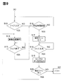
- FIG. 9 shows a control sequence of the suction fan 304 of the fixing unit 11 after step S7 of FIG. 1 of the first embodiment and FIG. 8 of the second embodiment.
- control unit A waits for an input of an image forming job for a predetermined time (S13, S16).
- control unit A executes the image forming operation of the input job until the job ends (S14, S15).
- the control unit A stops the air suction operation of the air suction unit 300 in the fixing unit 11 in waiting for the input of the image forming job in step S13 or after a predetermined time has elapsed from the end of the job in step S15 (suction fan 304). : Off) (S17). Then, in this state, input of an image forming job is waited (S18).
- the control unit A uses the recording material detection signal from the recording material sensor 51 of the first sheet 16 of the input image forming job (S19: ON signal output) ), The air suction operation of the air suction unit 300 is started (S20). That is, the suction fan 304 is turned on.
- control unit A checks the rotation of the suction fan 304 by using a rotation detection sensor (not shown). If the rotation detection sensor cannot detect the rotation of the suction fan 304, it is determined that the apparatus is abnormal, an error is displayed on the display section C2 of the operation section C, and the operation of the apparatus 100 is stopped (S21).
- the control unit A executes the image forming operation of the input image forming job with the suction fan 304 turned on in step S20 (S14).
- a feature of the operation flow of FIG. 9 is that the control unit A controls the air suction unit based on a detection signal from the sensor 51 of the first sheet of a job input in a state where the air suction operation of the air suction unit 300 is stopped. This is to start the air suction operation of 300 (S17 to S20). That is, the trigger for switching the suction fan 304 from off to on is performed when the paper 16 turns on the sensor 51.
- the air suction operation of the air suction unit 300 is stopped while waiting for a job input (S16 to S18). Therefore, since there is no drive power for the suction fan 304 and unnecessary air flow in the IR irradiator 13 during that time, the power for controlling the temperature of the belt 31 by the IR irradiator 13 is reduced.
- the image forming apparatus 100 is an image forming apparatus that performs UV curing and fixing using a liquid developer.
- an IR irradiation device 13 and a UV irradiation device 12 are arranged in the fixing unit 11.
- the fixing unit 11 has no UV irradiation device 12 and has an IR irradiation device. It has only 13.
- FIGS. 11 and 12 are flowcharts of the standby operation of the fixing unit 11 in a case where the fixing unit 11 has only the IR irradiation device 13 without the UV irradiation device 12, respectively.
- FIG. 11 corresponds to the flowchart of FIG. 1 of the first embodiment
- FIG. 12 corresponds to the flowchart of FIG. 8 of the second embodiment. Steps S3 and S9 relating to control of the UV irradiation device 12 are omitted, respectively. ing.
- the control sequence of the suction fan 304 of the fixing unit 11 after step S7 is the same as that of FIG. 9 of the third embodiment.
- an image forming apparatus having a reduced standby time is provided.
Abstract
An image forming device 10 activates an infrared irradiation section in response to power being supplied thereto and starts an air suction operation by an air suction section 300 after the temperature of an infrared radiation member 305 in the infrared irradiation section 13 reaches a prescribed temperature.
Description
本発明は、画像形成部で作成された未定着画像を赤外線照射により加熱し記録材上への定着補助または定着させるための赤外線照射装置を配置した定着装置を備えた画像形成装置に関する。
The present invention relates to an image forming apparatus provided with a fixing device provided with an infrared irradiating device for heating an unfixed image created in an image forming unit by infrared irradiation and assisting or fixing the image onto a recording material.
例えば、転写方式の電子写真プロセスを用いた画像形成装置において、画像形成部により作成されたトナー像は転写装置により記録材(以下、用紙とも記す)へ転写され、トナー像を転写された用紙は、定着装置へと搬送される。そして、未定着トナー像が載った用紙は定着装置内に配置された定着部材と加圧部材から形成される定着ニップ間を通過する。その過程において加熱と加圧が同時に行われトナー像を用紙に固着させるような定着方式が一般的に採用されてきた。定着部材や加圧部材は主にローラやベルトから構成され、加熱部材は定着部材や加圧部材内部に配置されることが多い。
For example, in an image forming apparatus using a transfer type electrophotographic process, a toner image created by an image forming unit is transferred to a recording material (hereinafter, also referred to as a sheet) by a transfer device, and a sheet on which the toner image is transferred is Is transported to the fixing device. Then, the sheet on which the unfixed toner image is placed passes between a fixing nip formed by a fixing member and a pressing member arranged in the fixing device. In that process, a fixing method in which heating and pressurization are performed simultaneously to fix the toner image on the sheet has been generally adopted. The fixing member and the pressing member mainly include a roller and a belt, and the heating member is often disposed inside the fixing member and the pressing member.
上記の定着方式においては、定着部材に未定着トナー像を加圧部材により圧接させ、トナーの加熱と加圧を同時に行うため用紙が定着ニップ通過時、用紙自身が持つ水分量や剛性に応じて用紙自身が変形してしまうカールや皺などが発生することがある。
In the above-described fixing method, an unfixed toner image is pressed against a fixing member by a pressing member, and heating and pressing of the toner are performed at the same time. Curl and wrinkles that may deform the paper itself may occur.
また、定着部材の定着温度を高くしすぎるとトナーが溶融しすぎてトナー同士の凝集力が低下し定着部材に溶融して定着部材側に取去られる高温オフセット現象という問題が発生する。特に幅の小さい用紙の通紙時、定着部材の用紙が接触しない部分で定着部材の温度が上昇することがある。この現象を非通紙部昇温と呼ぶ。その後、先の用紙よりも幅の大きい用紙を通紙した場合に高温オフセット現象が発生することがある。
Further, if the fixing temperature of the fixing member is set too high, the toner melts too much and the cohesive force between the toners is reduced, causing a problem of a high-temperature offset phenomenon in which the toner melts into the fixing member and is removed to the fixing member side. In particular, when a sheet having a small width is passed, the temperature of the fixing member may increase in a portion of the fixing member where the sheet does not contact. This phenomenon is called a non-sheet passing portion temperature increase. Thereafter, when a sheet wider than the preceding sheet is passed, a high-temperature offset phenomenon may occur.
そこで、上記定着オフセット問題の解決に着目した提案もされている。特開2007−29582号公報には、未定着トナー像を転写した用紙を定着部材と加圧部材から構成される定着ニップは通過させるものの熱源を定着部材、加圧部材の内部ではなく、その上流に配置する装置構成が記載されている。これは、加熱と加圧の機能を分離することで定着オフセットに課題解決を図るものである。その熱源としては赤外線を照射可能な赤外線照射装置を使用している。
Therefore, proposals have been made focusing on solving the fixing offset problem. Japanese Patent Application Laid-Open No. 2007-29582 discloses that although a sheet on which an unfixed toner image is transferred passes through a fixing nip composed of a fixing member and a pressing member, a heat source is not located inside the fixing member and the pressing member but upstream thereof. Is described. This is to solve the problem of fixing offset by separating the functions of heating and pressing. As the heat source, an infrared irradiation device capable of irradiating infrared light is used.
特開2009−222896号公報には、加圧部材が未定着トナー像を載せた用紙に非接触で定着可能な光照射定着(フラッシュ定着)を採用した装置構成が記載されている。これは、先の定着高温オフセット問題に加え、定着装置通過後の用紙自身のカールや皺の問題解決とシール素材や封筒などの特殊な用紙対応、さらには、定着部材と加圧部材のニップでは不可能な超高速印刷にも着目した提案である。光照射は遠赤外線を照射可能な遠赤外線照射装置を用いる。
Japanese Unexamined Patent Application Publication No. 2009-222896 describes an apparatus configuration that employs light irradiation fixing (flash fixing) in which a pressing member can fix a sheet on which an unfixed toner image is mounted in a non-contact manner. This is in addition to the above-mentioned fixing hot offset problem, solving the curl and wrinkle problems of the paper itself after passing through the fixing device, and dealing with special paper such as seal materials and envelopes.In addition, the nip between the fixing member and the pressure member It is a proposal that focuses on impossible super-high-speed printing. Light irradiation uses a far-infrared irradiation device that can emit far-infrared rays.
特願2017−7790号公報には、定着性確保のために紫外線により硬化する液体現像剤を使用し、液体現像剤を記録材上に定着するための紫外線照射装置を備えた画像形成装置が記載されている。これは、さらなる高速化をめざす場合、赤外線を用いた光照射定着だけでは定着性が十分確保できないという問題に着目したものである。紫外線照射装置を用いた定着器により液体現像剤を瞬時硬化が可能で高速UVオフセット印刷機やUVインクジェット印刷機の乾燥等に用いられている。
Japanese Patent Application No. 2017-7790 discloses an image forming apparatus which uses a liquid developer which is cured by ultraviolet rays for securing the fixing property and has an ultraviolet irradiation device for fixing the liquid developer on a recording material. Have been. This focuses on the problem that the fixing property cannot be sufficiently secured only by light irradiation fixing using infrared rays in order to further increase the speed. A liquid developer can be instantly cured by a fixing device using an ultraviolet irradiation device, and is used for drying a high-speed UV offset printing machine or a UV inkjet printing machine.
[発明が解決しようとする課題]
特開2007−29582号公報、特開2009−222896号公報、特願2017−7790号公報に記載された定着装置のように画像形成装置の高速化や高画質化を実現するために、赤外線照射装置や、赤外線照射装置と紫外線照射装置を組合せた定着装置は定着部に対して未定着画像を載せた記録材を搬送する必要がある。その記録材搬送装置としてエアー吸引を利用したものと静電気吸着を利用したものが考えられるが、エアー吸引の方が有効となる。なぜならば、静電手段を用いた場合、記録材上の未定着トナー像を乱す可能性が考えられるためである。 [Problems to be solved by the invention]
In order to realize a high-speed and high-quality image forming apparatus as in a fixing device described in JP-A-2007-29582, JP-A-2009-222896, and Japanese Patent Application No. 2017-7790, infrared irradiation is performed. An apparatus or a fixing device combining an infrared irradiation apparatus and an ultraviolet irradiation apparatus needs to convey a recording material on which an unfixed image is placed to a fixing unit. As the recording material transporting device, a device using air suction and a device using electrostatic adsorption can be considered, but air suction is more effective. This is because the use of electrostatic means may disturb the unfixed toner image on the recording material.
しかし、エアーを用いる場合には次のような課題があった。即ち、赤外線照射装置はその能力を発揮するためにある温度に達しなければならない。しかし、記録材搬送部でのエアー吸引を行うことで赤外線照射装置を冷却する効果が生じ、特に画像形成装置のスタンバイ動作時(立ち上げ時)、そのスタンバイ時間(ウォームアップタイム)を延ばしてしまう課題があった。
However, when air was used, there were the following problems. That is, the infrared irradiator must reach a certain temperature in order to exhibit its capabilities. However, the effect of cooling the infrared irradiating device is produced by performing the air suction in the recording material conveying unit, and the standby time (warm-up time) is prolonged, particularly during the standby operation (start-up) of the image forming apparatus. There were challenges.
そこで本発明の目的は上記の課題を解消してスタンバイ時間の短縮化を可能にした画像形成装置を提供することを目的としている。
[課題を解決するための手段] SUMMARY OF THE INVENTION It is an object of the present invention to provide an image forming apparatus which can solve the above-mentioned problem and can reduce the standby time.
[Means for solving the problem]
[課題を解決するための手段] SUMMARY OF THE INVENTION It is an object of the present invention to provide an image forming apparatus which can solve the above-mentioned problem and can reduce the standby time.
[Means for solving the problem]
本発明の一態様によれば、記録材上に未定着画像を形成する画像形成部と、通気性を有する無端状の回動可能なベルトと、前記ベルトの内側に配置さベルト上に記録材を吸引保持するための負圧を前記ベルトを介して付与する空気吸引部と、を備え、前記画像形成部により未定着画像が形成された記録材をベルト上に吸引保持して搬送する記録材搬送機構と、前記ベルトの記録材搬送側のベルト部分に対向して配置され、ベルト上に吸引保持されて搬送される記録材に赤外線を照射して画像加熱するための赤外線照射部と、前記記録材搬送機構と前記赤外線照射部の動作を制御する制御部と、を有し、前記制御部は、画像形成装置の電源投入されたことに応じて前記赤外線照射部をオンにし、前記赤外線照射部の赤外線放射部材の温度が所定の温度に達した後に前記空気吸引部の空気吸引動作を開始させる画像形成装置が提供される。
According to one aspect of the present invention, an image forming unit that forms an unfixed image on a recording material, an endless rotatable belt having air permeability, and a recording material disposed on a belt disposed inside the belt An air suction unit that applies a negative pressure for sucking and holding the recording material through the belt, and the recording material on which the unfixed image is formed by the image forming unit is suction-held on the belt and conveyed. A conveying mechanism, an infrared irradiator for heating the image by irradiating the recording material conveyed while being sucked and held on the belt with an infrared ray irradiating unit, which is disposed to face a belt portion of the belt on the recording material conveying side, and A control unit for controlling the operation of the recording material transport mechanism and the infrared irradiation unit, wherein the control unit turns on the infrared irradiation unit in response to power-on of the image forming apparatus; Temperature of the infrared radiation member The image forming apparatus is provided in which after reaching the temperature the start of air suction operation of the air suction part.
図1は実施例1における定着部のスタンバイ動作のフローチャートである。
FIG. 1 is a flowchart of the standby operation of the fixing unit according to the first embodiment.
図2は実施例1における画像形成装置の縦断正面模式図である。
FIG. 2 is a schematic vertical front view of the image forming apparatus according to the first embodiment.
図3は同画像形成装置の定着部(定着装置)の部分の拡大模式図である。
FIG. 3 is an enlarged schematic view of a fixing unit (fixing device) of the image forming apparatus.
図4は制御系統のブロック図である。
Fig. 4 is a block diagram of the control system.
図5は紫外線硬化型の液体現像剤による画像の断面模式図である。
FIG. 5 is a schematic cross-sectional view of an image formed by an ultraviolet-curable liquid developer.
図6は現像剤温度に対する積算光量の相関図である。
FIG. 6 is a correlation diagram of the integrated light amount with respect to the developer temperature.
図7は吸引ファンの有(オン)、無(オフ)での搬送ベルト温度推移図である。
FIG. 7 is a transition diagram of the transport belt temperature when the suction fan is provided (ON) or not (OFF).
図8は実施例2における定着部のスタンバイ動作のフローチャートである。
FIG. 8 is a flowchart of the standby operation of the fixing unit according to the second embodiment.
図9は実施例3における吸引ファン制御のフローチャートである。
FIG. 9 is a flowchart of suction fan control in the third embodiment.
図10は実施例4における画像形成装置の縦断正面模式図である。
FIG. 10 is a schematic vertical front view of the image forming apparatus according to the fourth embodiment.
図11は実施例4における定着部のスタンバイ動作のフローチャート(その1)である。
FIG. 11 is a flowchart (part 1) of the standby operation of the fixing unit in the fourth embodiment.
図12は実施例4における定着部のスタンバイ動作のフローチャート(その2)である。
FIG. 12 is a flowchart (part 2) of the standby operation of the fixing unit in the fourth embodiment.
以下に、本発明の好ましい実施形態を、紫外線硬化型の液体キャリアとトナーを含む液液体現像剤を用い紫外線硬化定着を行う画像形成装置を例に添付の図面に基づいて説明する。
Hereinafter, a preferred embodiment of the present invention will be described with reference to the accompanying drawings, taking as an example an image forming apparatus that performs ultraviolet curing and fixing using a liquid liquid developer containing an ultraviolet curing liquid carrier and a toner.
(画像形成装置の全体的構成)
(Overall configuration of image forming apparatus)
図2は本実施例1における画像形成装置100の縦断正面模式図である。以下の説明において、画像形成装置100の正面(前面、手前側)とは図1の紙面において手前側、背面(後面、奥側)とがその反対側である。左右とは装置100を正面から見て左と右である。上下とは重力方向において上と下である。上流側と下流側は記録材搬送方向において上流側と下流側である。また、紫外線をUV又はUV光、赤外線をIR又はIR光と記す。
FIG. 2 is a schematic vertical front view of the image forming apparatus 100 according to the first embodiment. In the following description, the front side (front side, front side) of the image forming apparatus 100 is the opposite side of the front side and the back side (rear side, back side) in the paper of FIG. The left and right are the left and right when the apparatus 100 is viewed from the front. Up and down are above and below in the direction of gravity. The upstream side and the downstream side are the upstream side and the downstream side in the recording material conveyance direction. In addition, ultraviolet light is referred to as UV or UV light, and infrared light is referred to as IR or IR light.
この画像形成装置100は転写方式の電子写真プロセスを用いたプリンタである。即ち、当該装置100はパソコン等のホスト装置Bから制御部(制御回路部)Aに投入(入力)された画像形成ジョブ(プリントジョブ)に基づいて画像形成動作(印刷動作)して記録材16に対してトナー画像形成を行う。画像形成ジョブは、画像データ、使用する記録材の種類等に関する情報、枚数、部数、後処理情報等のプリント条件情報が付加された画像形成指示のことである。
The image forming apparatus 100 is a printer using a transfer type electrophotographic process. That is, the apparatus 100 performs an image forming operation (printing operation) based on an image forming job (print job) input (input) from a host device B such as a personal computer to a control unit (control circuit unit) A, and performs recording on the recording material 16. To form a toner image. The image forming job is an image forming instruction to which print condition information such as image data, information on the type of recording material to be used, the number of copies, the number of copies, and post-processing information is added.
制御部Aは当該装置100の全ての装置制御、画像形成動作のシーケンス制御を司る。Cは画像形成装置100の操作部(ユーザーインターフェース)である。操作部Cは、図4のように、メイン電源スイッチMSW、各種の情報を制御部Aに入力するためのテンキーや各種ボタン類C1、液晶式タッチパネル等の表示部C2等を有している。表示部C2には制御部Aやホスト装置Bにより各種の情報が表示される。表示部C2からも各種の情報を制御部Aに入力することができる。
The control unit A controls all the devices of the device 100 and the sequence control of the image forming operation. C denotes an operation unit (user interface) of the image forming apparatus 100. As shown in FIG. 4, the operation unit C includes a main power switch MSW, numeric keys and various buttons C1 for inputting various information to the control unit A, a display unit C2 such as a liquid crystal touch panel, and the like. Various information is displayed on the display unit C2 by the control unit A and the host device B. Various information can also be input to the control unit A from the display unit C2.
この装置100は、トナーとUV光により硬化(紫外線硬化型)する液体キャリア(紫外線硬化液、紫外線硬化剤)を含むと液体現像剤を用いて記録材上に未定着画像を形成する画像形成部10を備える。また、装置100は、記録材16上に形成された画像15を記録材16に定着する定着部(定着装置)11を備える。
The image forming unit 100 forms an unfixed image on a recording material using a liquid developer when a liquid carrier (ultraviolet curable liquid, ultraviolet curable agent) that is cured (ultraviolet curable) by toner and UV light is included. 10 is provided. Further, the apparatus 100 includes a fixing unit (fixing device) 11 for fixing the image 15 formed on the recording material 16 to the recording material 16.
記録材16は、画像形成装置100によって画像が形成されるシート状の記録媒体(メディア)であり、例えば、普通紙、コート紙、はがきや封筒、OHPシートや樹脂性フィルムであっても良い。以下においては、記録材を用紙または紙とも記す。用紙16は給紙カセット25に束状態で収容されている。給紙カセット25内の用紙16は、給紙機構2によって1枚に分離され、搬送路26を経由して画像形成部10へと給送される。給紙カセット25は、複数段配置し、用紙16の材質や大きさの異なるものを画像形成装置100内に予め配置しておくことも可能である。
The recording material 16 is a sheet-like recording medium (media) on which an image is formed by the image forming apparatus 100, and may be, for example, plain paper, coated paper, a postcard or envelope, an OHP sheet, or a resin film. Hereinafter, the recording material is also referred to as paper or paper. The sheets 16 are stored in a sheet cassette 25 in a bundle. The paper 16 in the paper feed cassette 25 is separated into one by the paper feed mechanism 2, and is fed to the image forming unit 10 via the transport path 26. The paper feed cassettes 25 may be arranged in a plurality of stages, and sheets having different materials and sizes of the paper 16 may be arranged in the image forming apparatus 100 in advance.
画像形成部10は、像担持体としての円筒状の感光ドラム1を有する。また、画像形成部10は、感光ドラム1の回りに配置された電子写真画像形成手段(プロセス機器)を有する。具体的には、感光ドラム1の表面を一様に帯電させる帯電部10a、露光により静電潜像を作成する露光部10b、静電潜像された画像を先述の液体現像剤により現像する現像部10c、転写ローラ4、不要な液体現像剤を取り除くクリーナ部10dである。
The image forming unit 10 has the cylindrical photosensitive drum 1 as an image carrier. Further, the image forming unit 10 includes an electrophotographic image forming unit (process device) disposed around the photosensitive drum 1. Specifically, a charging section 10a for uniformly charging the surface of the photosensitive drum 1, an exposure section 10b for forming an electrostatic latent image by exposure, and a development for developing the electrostatic latent image with the liquid developer described above. The section 10c, the transfer roller 4, and a cleaner section 10d for removing unnecessary liquid developer.
本実施例における感光ドラム1は、厚みが3mm、外径84mmのアルミニウム製シリンダーで表面に有機感光体表層を持ち、長手の幅(用紙搬送方向と略直交する方向の長さ)が370mmである。
The photosensitive drum 1 in the present embodiment is an aluminum cylinder having a thickness of 3 mm and an outer diameter of 84 mm, has an organic photosensitive member surface layer on the surface, and has a longitudinal width (length in a direction substantially orthogonal to the paper conveying direction) of 370 mm. .
転写ローラ4は芯金がSUM材にKNメッキを施した金属軸の周りにウレタン製のゴムを巻付けた2種類の材質から構成されるローラである。そして、感光ドラム1に加圧機構(不図示)により加圧されて接触しニップ(転写ニップ)を形成するように配置している。
(4) The transfer roller 4 is a roller composed of two types of materials in which a core metal is formed by winding urethane rubber around a metal shaft obtained by subjecting a SUM material to KN plating. The photosensitive drum 1 is arranged so as to be pressed and contacted by a pressing mechanism (not shown) to form a nip (transfer nip).
感光ドラム1は制御部Aで制御される駆動手段である駆動モータM1(メインモータ:図4)によって、感光ドラム1の中心支軸1aを中心に図2中の矢印R1方向に所定の周速度(プロセススピード)にて回転駆動される。この時、転写ローラ4も駆動モータM1によりニップにおいて感光ドラム1の回転方向と同一の矢印R2方向に回転駆動される。
The photosensitive drum 1 is driven by a drive motor M1 (main motor: FIG. 4), which is a drive unit controlled by the control unit A, at a predetermined peripheral speed in the direction of arrow R1 in FIG. (Process speed). At this time, the transfer roller 4 is also driven to rotate at the nip by the drive motor M1 in the direction of the arrow R2, which is the same as the rotation direction of the photosensitive drum 1.
給紙カセット25から送り出される用紙16は感光ドラム1上に先述の現像部10cにより現像されたトナー像(液体現像剤の画像)と同期するように感光ドラム1と転写ローラ4から形成されるニップに進入するように制御される。そして、用紙16は転写ニップで挟持搬送されていく過程で、感光ドラム1上に現像されたトナー像が用紙16上の任意の位置に順次に転写される。つまり、用紙16上(記録材上)には液体現像剤による未定着画像15が転写形成される。画像形成部10にて画像15が形成された用紙16は、搬送路27を通って定着部11に搬送される。
The paper 16 sent out from the paper feed cassette 25 is formed on the photosensitive drum 1 by the nip formed by the photosensitive drum 1 and the transfer roller 4 so as to synchronize with the toner image (image of the liquid developer) developed by the developing unit 10c. Is controlled to enter. The toner image developed on the photosensitive drum 1 is sequentially transferred to an arbitrary position on the paper 16 while the paper 16 is being nipped and conveyed by the transfer nip. That is, the unfixed image 15 of the liquid developer is transferred and formed on the paper 16 (on the recording material). The sheet 16 on which the image 15 has been formed by the image forming unit 10 is conveyed to the fixing unit 11 through the conveying path 27.
51は搬送路27に配設したジャム検知センサ(記録材センサ)である。このセンサ51は、後述する定着部11における用紙搬送装置(記録材搬送機構)30よりも用紙搬送方向上流側(記録材搬送方向上流側)における搬送路(記録材搬送路)27に配置されている。
# 51 denotes a jam detection sensor (recording material sensor) provided in the transport path 27. The sensor 51 is disposed on a transport path (recording material transport path) 27 on the upstream side in the paper transport direction (upstream on the recording material transport direction) with respect to the paper transport apparatus (recording material transport mechanism) 30 in the fixing unit 11 described later. I have.
このセンサ51の位置に用紙16が存在していないときには当該センサ51はオフ信号を、用紙16が存在しているときには当該センサ51はオン信号を出力しており、そのオフ信号とオン信号が制御部Aに入力する。制御部Aは給紙カセット25からの用紙16の給紙開始後において、センサ51から入力するオン信号やオフ信号がシークエンス上の規定時間より長かったり短かったりした場合には用紙ジャムが生じたと判断する。
When the paper 16 is not present at the position of the sensor 51, the sensor 51 outputs an off signal, and when the paper 16 is present, the sensor 51 outputs an on signal, and the off signal and the on signal are controlled. Input to Part A. The control unit A determines that a paper jam has occurred if the ON signal or the OFF signal input from the sensor 51 is longer or shorter than a specified time on the sequence after the paper feed from the paper feed cassette 25 is started. I do.
即ち、制御部Aは用紙搬送に伴う当該センサ51のオン信号とオフ信号の切り替りにより用紙16が正しいタイミングで給紙され、画像形成部10を通過したか否かを検知する。制御部Aは、給紙開始後、所定時間を経過してもセンサ51がオンしない、または、所定時間以上センサ51のオン信号があり続ける場合は用紙16が正しいタイミングで搬送できていないと判断する。この場合においては、制御部Aはジャム発生として画像形成装置100の画像形成動作を緊急停止させ、操作部Cやホスト装置Bの表示部にユーザーにジャム処理を促す表示をする。
That is, the control unit A detects whether or not the sheet 16 has been fed at the correct timing and has passed through the image forming unit 10 by switching between the ON signal and the OFF signal of the sensor 51 accompanying the sheet conveyance. The control unit A determines that the sheet 16 cannot be conveyed at the correct timing if the sensor 51 does not turn on even if a predetermined time has elapsed after the start of sheet feeding, or if the ON signal of the sensor 51 continues for a predetermined time or more. I do. In this case, the control unit A urgently stops the image forming operation of the image forming apparatus 100 as a jam has occurred, and displays on the operation unit C and the display unit of the host device B a message urging the user to perform the jam processing.
尚、本実施例において画像形成部10は電子写真方式−直接転写方式の構成としたが用紙16への画像形成方法はこれに限らない。例えば、感光ドラム1を中間転写ベルトとする中間転写方式の構成としても良い。具体的には、画像形成手段が液体現像剤を用いて感光ドラム上に形成した画像を1次転写ローラが中間転写体に1次転写し、転写手段4は2次転写ローラとし中間転写体上の画像を用紙16に転写する。
In the present embodiment, the image forming unit 10 has the configuration of the electrophotographic type-direct transfer type, but the image forming method on the paper 16 is not limited to this. For example, an intermediate transfer system using the photosensitive drum 1 as an intermediate transfer belt may be used. Specifically, an image formed by the image forming means on the photosensitive drum using a liquid developer is primarily transferred by a primary transfer roller to an intermediate transfer member, and the transfer means 4 is a secondary transfer roller and is formed on the intermediate transfer member. Is transferred to the paper 16.
定着部11は、用紙16にIR光を照射するIR照射装置(赤外線照射部)13と、用紙16にUV光を照射するUV照射装置(紫外線照射部)12と、用紙16を搬送する用紙搬送装置(記録材搬送機構)30を含む。
The fixing unit 11 includes an IR irradiator (infrared irradiator) 13 that irradiates the paper 16 with IR light, a UV irradiator (ultraviolet irradiator) 12 that irradiates the paper 16 with UV light, and a paper transport that transports the paper 16. An apparatus (recording material transport mechanism) 30 is included.
画像形成部10から搬送路27を通って定着部11に搬送された、液体現像剤による未定着の画像15を載せた用紙16は定着部11の用紙搬送装置30にて引き続き搬送される。そして、IR照射装置13の下を通過する過程において、IR光を照射されて加熱され自身の温度を所定の温度に高められ、その直後にUV照射装置12の下を通過する過程において、UV光の照射を受ける。このUV光の照射により、用紙上の液体現像剤による未定着画像15が固着画像としてUV硬化定着される。
(4) The sheet 16 on which the unfixed image 15 of the liquid developer is conveyed from the image forming unit 10 to the fixing unit 11 through the conveying path 27, is continuously conveyed by the sheet conveying device 30 of the fixing unit 11. In the process of passing under the IR irradiating device 13, the device is irradiated with IR light and heated to raise its own temperature to a predetermined temperature. Irradiated. By the irradiation of the UV light, the unfixed image 15 of the liquid developer on the sheet is fixed by UV curing as a fixed image.
ここで、本実施例1で使用しているUV硬化型の液体現像剤とその硬化に関するメカニズムについて簡単に説明する。
Here, the UV-curable liquid developer used in the first embodiment and the mechanism related to its curing will be briefly described.
図5は用紙16上に形成されているUV硬化型の液体現像剤による未定着画像15の断面模式図である。この画像15はUV光により硬化する液体キャリア(紫外線硬化剤)21中にトナー22が分散している。液体キャリア21は少なくとも光重合剤と紫外線硬化剤のモノマーから構成されている。トナー22はトナー22の母体であるトナー樹脂23と色剤24から構成されている。
FIG. 5 is a schematic cross-sectional view of the unfixed image 15 formed on the paper 16 by the UV-curable liquid developer. In the image 15, a toner 22 is dispersed in a liquid carrier (ultraviolet curing agent) 21 which is cured by UV light. The liquid carrier 21 is composed of at least monomers of a photopolymerizing agent and an ultraviolet curing agent. The toner 22 includes a toner resin 23 which is a base of the toner 22 and a colorant 24.
例えば、カチオン重合の場合、UV光が液体キャリア21にあたるとUV光で励起された光重合開始剤が酸を発し、発生した酸とモノマーが重合反応を開始し、液体キャリア21が硬化を開始するものである。従って、UV硬化型の液体現像剤による未定着画像15の定着は、UV光の照射によって用紙16上の液体キャリア21を硬化させて、液体キャリア21とトナー22を用紙16上に固着させることでなされる。
For example, in the case of cationic polymerization, when the UV light impinges on the liquid carrier 21, the photopolymerization initiator excited by the UV light emits an acid, the generated acid and the monomer start a polymerization reaction, and the liquid carrier 21 starts to harden. Things. Therefore, the fixing of the unfixed image 15 by the UV-curable liquid developer is performed by curing the liquid carrier 21 on the sheet 16 by irradiating the UV light and fixing the liquid carrier 21 and the toner 22 on the sheet 16. Done.
定着部11にて定着処理された用紙16は、排出搬送路28を通過して画像形成物(成果物)として排出ユニット(不図示)にて機外に排出される、或いはフィニッシャ部(不図示)に導入される。フィニッシャ部は定着処理された用紙16に対して各種のフィニッシャ処理、例えば、スティブル処理、パンチ処理、製本処理等を行う後処理ユニットである。
(定着部の詳細構成) Thepaper 16 subjected to the fixing process in the fixing unit 11 is discharged to the outside of the apparatus by a discharge unit (not shown) as an image formed product (product) through a discharge conveyance path 28, or a finisher unit (not shown). ). The finisher unit is a post-processing unit that performs various types of finisher processing, such as stable processing, punching processing, and bookbinding processing, on the paper 16 on which the fixing processing has been performed.
(Detailed configuration of fixing unit)
(定着部の詳細構成) The
(Detailed configuration of fixing unit)
図3は図2の画像形成装置100における定着部(定着装置)11の部分の拡大模式図である。定着部11は大きく分類して、IR照射装置13、UV照射装置12、用紙搬送装置(記録材搬送機構)30の3つユニットから構成される。
(1)用紙搬送装置 FIG. 3 is an enlarged schematic diagram of a fixing unit (fixing device) 11 in theimage forming apparatus 100 of FIG. The fixing unit 11 is roughly classified into three units: an IR irradiator 13, a UV irradiator 12, and a paper transport device (recording material transport mechanism) 30.
(1) Paper transport device
(1)用紙搬送装置 FIG. 3 is an enlarged schematic diagram of a fixing unit (fixing device) 11 in the
(1) Paper transport device
図3を参照して、液体現像剤による未定着画像15が上面に形成されて画像形成部10から搬送された用紙16は定着部11に矢印X1から進入する。用紙搬送装置30は定着部11に進入した用紙16を矢印Y1の方向に搬送して先述の排出ユニット(不図示)或いはフィニッシャ部(不図示)に引き渡すユニットである。
(3) Referring to FIG. 3, unfixed image 15 formed of the liquid developer is formed on the upper surface, and sheet 16 conveyed from image forming unit 10 enters fixing unit 11 from arrow X1. The paper transporting device 30 is a unit that transports the paper 16 that has entered the fixing unit 11 in the direction of arrow Y1 and delivers it to the above-described discharge unit (not shown) or the finisher unit (not shown).
用紙搬送装置30は、多数の穴が設けられた無端状の搬送ベルト(通気性を有する無端状の回動可能なベルト、穴あきベルト:以下、ベルトと記す)31を備えている。また、用紙搬送装置30は、このベルト31を回動可能に張架するベルト張架部材(ベルト支持ローラ)としての駆動ローラ35および従動ローラ36、37、38を備えている。また、用紙搬送装置30は、駆動ローラ35を介してベルト31を回動させる搬送駆動モータM2(図4)を備える。
The paper transport device 30 is provided with an endless transport belt (an endless rotatable belt having air permeability, a perforated belt: hereinafter referred to as a belt) 31 provided with a number of holes. Further, the sheet transporting device 30 includes a driving roller 35 and driven rollers 36, 37, and 38 as a belt stretching member (belt supporting roller) that stretches the belt 31 rotatably. Further, the paper transport device 30 includes a transport drive motor M2 (FIG. 4) for rotating the belt 31 via the drive roller 35.
ベルト31は搬送駆動モータM2の駆動により矢印R3の方向に所定の周速度(プロセススピード)で回動する。本実施例1におけるベルト31は、幅が350mm、周長は900mm、材質はPI樹脂を採用している。ベルト31は周速度785mm/sで回転をしている。
(4) The belt 31 is rotated at a predetermined peripheral speed (process speed) in the direction of the arrow R3 by driving the transport drive motor M2. The belt 31 according to the first embodiment has a width of 350 mm, a circumference of 900 mm, and a PI resin. The belt 31 rotates at a peripheral speed of 785 mm / s.
ベルト31の内側にはベルト上に用紙16を吸引保持するための空気吸引部(エアー吸引システム)300が配置されている。空気吸引部300は、ベルト31の上行側ベルト部分(記録材搬送側のベルト部分)の内面を上面で支持する通気性を有する平板状のベルト支持板(吸着板)としての穴あきプレート(穴あき板)301を有する。また、空気吸引部300は、このプレート301の下面側にプレート301に密着するように固定されて配置された耐熱樹脂(本実施例ではPPS樹脂)から成る吸引チャンバー302を有する。
空 気 An air suction unit (air suction system) 300 for sucking and holding the paper 16 on the belt 31 is disposed inside the belt 31. The air suction unit 300 includes a perforated plate (hole) as a flat belt supporting plate (suction plate) having air permeability for supporting the inner surface of the ascending side belt portion (belt portion on the recording material conveying side) of the belt 31 on the upper surface. (A perforated plate) 301. Further, the air suction unit 300 has a suction chamber 302 made of a heat-resistant resin (PPS resin in this embodiment) fixed and arranged on the lower surface side of the plate 301 so as to be in close contact with the plate 301.
吸引チャンバー302は二室あり、それぞれのチャンバー302には空気の通過するダクト303が連結され、その先に制御部Aで制御されるエアー吸引用のファン304が取り付けられている。ベルト31の上行側のベルト部分の内面はプレート301の上面に摺動可能に支持されている。ベルト31が回転駆動されるとベルト内面がプレート301の上面に対して接しながら摺動移動(摺擦)する。
There are two suction chambers 302, and a duct 303 through which air passes is connected to each of the chambers 302, and an air suction fan 304 controlled by the control unit A is attached to the front of the duct 303. The inner surface of the belt portion on the ascending side of the belt 31 is slidably supported on the upper surface of the plate 301. When the belt 31 is driven to rotate, the inner surface of the belt 31 slides (slids) while being in contact with the upper surface of the plate 301.
空気吸引部300はベルト31上に用紙16を吸引保持するための負圧を穴あきプレート301と穴あきベルト31を介して付与する。即ち、吸引ファン304が可動(オン)することにより、空気は穴あきベルト31の上面側全面で吸い込まれ吸引チャンバー302を経由して図3の紙面の奥側方向へのエアーフローを常時形成することで、用紙搬送装置30のエアーフローが形成される。
The air suction unit 300 applies a negative pressure for sucking and holding the paper 16 on the belt 31 via the perforated plate 301 and the perforated belt 31. That is, when the suction fan 304 is moved (turned on), air is sucked in on the entire upper surface side of the perforated belt 31 and always forms an air flow in the depth direction of the paper surface of FIG. Thus, an air flow of the sheet transport device 30 is formed.
そして、画像形成部10側から未定着画像15が載った用紙16がベルト31上に来た際は、ベルト31の上面に用紙16の未定着画像15の無い側(裏側)をベルト31上に吸着し回転するベルト31により矢印Y1の方向に搬送する。
Then, when the sheet 16 on which the unfixed image 15 is loaded comes from the image forming unit 10 side onto the belt 31, the side (back side) of the sheet 16 where the unfixed image 15 does not exist on the upper surface of the belt 31 is placed on the belt 31. It is conveyed in the direction of arrow Y1 by the belt 31 that is attracted and rotates.
その搬送過程において、画像形成部10により未定着画像15が形成された用紙16がベルト31の上行側のベルト部分に対向して配置されているIR照射装置13とUV照射装置12の下を順次に通過する。これにより、用紙16のIR光の照射による加熱(予備加熱:画像加熱)とUV光の照射による画像定着がなされる。即ち、定着ニップを形成せず、未定着画像15の面に非接触で定着が行われる。つまり、上記の用紙搬送装置30は未定着画像15には定着ローラや定着ベルトといった接触物無しに用紙16を搬送する。
In the transporting process, the sheet 16 on which the unfixed image 15 is formed by the image forming unit 10 sequentially passes under the IR irradiating device 13 and the UV irradiating device 12 which are arranged to face the belt portion on the ascending side of the belt 31. Pass through. As a result, heating of the sheet 16 by irradiation with IR light (preliminary heating: image heating) and image fixing by irradiation of UV light are performed. That is, fixing is performed without contacting the surface of the unfixed image 15 without forming a fixing nip. In other words, the above-described paper transporting device 30 transports the paper 16 to the unfixed image 15 without a contact object such as a fixing roller or a fixing belt.
上記の用紙搬送装置30によれば、未定着画像15を載せた用紙16はベルト31を支持している平板状の穴あきプレート301にならい、ほぼ平面状態となって搬送される。そして、用紙16はこの平面状態でIR照射装置13とUV照射装置12により未定着画像15の加熱とUV硬化定着が行われ、用紙16のカール等変形が抑制された状態で定着が完了される。即ち、平板状の穴あきプレート301は定着動作による用紙16のカール等の変形を抑制する。
According to the above-described paper transporting device 30, the paper 16 on which the unfixed image 15 is placed follows the flat plate-shaped perforated plate 301 supporting the belt 31, and is transported in a substantially planar state. The unfixed image 15 is heated and UV-cured and fixed by the IR irradiating device 13 and the UV irradiating device 12 in the flat state of the sheet 16, and the fixing is completed in a state where the curl of the sheet 16 is suppressed. . That is, the flat plate 301 with holes suppresses deformation such as curling of the paper 16 due to the fixing operation.
上記のように、用紙搬送装置30において用紙16をエアー吸引しながら搬送するベルト部分の内側にベルト内面を支持する平板状の穴あきプレート301がある。そのため、未定着トナーが用紙上で定着するとき、用紙はベルト31すなわち平板状のプレート301に倣いまっすぐな状態(平らな状態)で保持されて定着が完了する。従って、用紙16の画像定着時のカール等の変形が防止され、用紙搬送装置30の下流側のローラ対に用紙16を確実に受け渡す効果がある。
As described above, the flat plate-shaped perforated plate 301 that supports the inner surface of the belt is provided inside the belt portion that transports the paper 16 while sucking the air in the paper transport device 30. Therefore, when the unfixed toner is fixed on the sheet, the sheet is held in a straight state (flat state) following the belt 31, that is, the flat plate 301, and the fixing is completed. Therefore, the paper 16 is prevented from being deformed such as curl at the time of fixing an image, and the paper 16 is surely transferred to the pair of rollers on the downstream side of the paper transport device 30.
本実施例においては、用紙搬送装置30は、画像形成部10により画像15が形成された用紙16をベルト31上にエアー吸引により担持し、用紙16がIR照射装置13とUV照射装置12の下を順次に通過するように、用紙16を搬送する。即ち、IR照射装置13とUV照射装置12はベルト31の上行側のベルト部分の直上にベルトに対向して用紙搬送方向の上流側と下流側とに隣接して並べて配置されている。
In this embodiment, the paper transport device 30 holds the paper 16 on which the image 15 is formed by the image forming unit 10 on a belt 31 by air suction, and the paper 16 is placed under the IR irradiation device 13 and the UV irradiation device 12. The paper 16 is conveyed so as to sequentially pass through. That is, the IR irradiator 13 and the UV irradiator 12 are arranged immediately above the belt portion on the ascending side of the belt 31 so as to face the belt and to be adjacent to the upstream side and the downstream side in the paper transport direction.
これにより、ベルト31上に担持されて搬送される用紙16の液体現像剤の画像15は、先ずIR照射装置13によるIR光の照射を受けて加熱され、次いでUV照射装置12によるUV光の照射を受けて定着される。
Thereby, the image 15 of the liquid developer on the paper 16 carried and conveyed on the belt 31 is first heated by being irradiated with the IR light by the IR irradiating device 13, and then is irradiated with the UV light by the UV irradiating device 12. Received and established.
用紙搬送装置30は、用紙を吸引搬送により搬送するので、IR照射位置及びUV照射位置では、用紙が搬送ローラ等でニップされない。すなわち、本実施形態における定着装置は、IR照射位置及びUV照射位置にて加圧されない定着装置である。
(4) Since the paper transport device 30 transports the paper by suction transport, the paper is not nipped by the transport rollers or the like at the IR irradiation position and the UV irradiation position. That is, the fixing device according to the present embodiment is a fixing device that is not pressurized at the IR irradiation position and the UV irradiation position.
ここで、UV照射位置とは、用紙の搬送方向の位置分布で見たときに、UV照射装置12による最大の照度(ピーク照度)となる位置を指す。また、IR照射位置とは、用紙の搬送方向の位置分布で見たときに、IR照射装置13のピーク照度の90%以上の照度を有する領域の中心となる位置を指す。
(IR照射装置の構成) Here, the UV irradiation position refers to a position at which the maximum illuminance (peak illuminance) by theUV irradiating device 12 is observed as viewed from the position distribution in the sheet conveyance direction. Further, the IR irradiation position refers to a position that is the center of an area having an illuminance of 90% or more of the peak illuminance of the IR irradiating device 13 when viewed in the position distribution in the sheet conveyance direction.
(Configuration of IR irradiation device)
(IR照射装置の構成) Here, the UV irradiation position refers to a position at which the maximum illuminance (peak illuminance) by the
(Configuration of IR irradiation device)
IR照射装置13は光源が波長1~15μmの遠赤外線の電磁波を放射する。有機物における化学結合は遠赤外領域に吸収特性があるため、本実施例にて使用するトナーを含む液体現像剤等の有機物は遠赤外を照射することで、効率よく加熱することが出来る。
The 照射 IR irradiator 13 emits a far-infrared electromagnetic wave whose light source has a wavelength of 1 to 15 μm. Since the chemical bond in the organic substance has an absorption characteristic in the far-infrared region, the organic substance such as the liquid developer containing the toner used in the present embodiment can be efficiently heated by irradiating the far-infrared ray.
本実施例において遠赤外線を放射する物(赤外線放射部材)として直径17mm、長さ450mm石英管305を採用している。石英管305の中心位置がベルト31から80mmの高さの位置に配置している。そして、未定着画像15を載せた用紙16を非接触で温度上昇させる。
In this embodiment, a quartz tube 305 having a diameter of 17 mm and a length of 450 mm is employed as an object (infrared radiation member) that emits far-infrared rays. The center position of the quartz tube 305 is located at a height of 80 mm from the belt 31. Then, the temperature of the sheet 16 on which the unfixed image 15 is placed is raised without contact.
石英管305の中にはニクロム線からなるフィラメント306が配置される。フィラメント306に通電を行うことによりフィラメント306が加熱され石英管305を通して遠赤外線を放射する。石英管305から放射される遠赤外線が効率よく用紙16に放射させる為、アルミニウム製反射傘307が石英管305を覆うように配置している。
フ ィ ラ メ ン ト A filament 306 made of a nichrome wire is arranged in the quartz tube 305. When the filament 306 is energized, the filament 306 is heated and emits far-infrared rays through the quartz tube 305. An aluminum reflector 307 is disposed so as to cover the quartz tube 305 so that far infrared rays emitted from the quartz tube 305 can be efficiently emitted to the paper 16.
そして、石英管305と反射傘307を組み合わせた物を2組配置し、反射傘307を2組み合わせた長さLは175mm、出力は2組で2600Wの出力としている。用紙16は785mm/sで通過する為、IR照射時間は0.22秒である。IR照射装置13の両脇には温度センサ(非接触温度計)308を配置しベルト31の温度を測定している。
(UV照射装置の構成) Then, two sets of a combination of thequartz tube 305 and the reflector 307 are arranged, the length L of the combination of the two reflectors 307 is 175 mm, and the output is 2600 W in two sets. Since the paper 16 passes at 785 mm / s, the IR irradiation time is 0.22 seconds. Temperature sensors (non-contact thermometers) 308 are arranged on both sides of the IR irradiation device 13 to measure the temperature of the belt 31.
(Configuration of UV irradiation device)
(UV照射装置の構成) Then, two sets of a combination of the
(Configuration of UV irradiation device)
IR照射装置13のすぐ下流側(記録材搬送方向下流側)にはUV照射装置12を配置している。UV照射装置12はUV光を放射するLEDを用いている。LED:Light Emitting Diode。UV硬化反応で重要な項目で「光科学変化は投射光量の内吸収された光によってのみ起こる」ということである。つまり、UV硬化においては光重合開始剤の吸収波長とUV光の発光波長が一致していることが重要である。
The UV irradiation device 12 is disposed immediately downstream of the IR irradiation device 13 (downstream of the recording material conveyance direction). The UV irradiation device 12 uses an LED that emits UV light. LED: Light \ Emitting \ Diode. An important item in the UV curing reaction is that "optical science changes are caused only by absorbed light out of the projected light amount". That is, in UV curing, it is important that the absorption wavelength of the photopolymerization initiator and the emission wavelength of the UV light match.
本実施例においては、照度ピーク波長385±5μm、照度ピーク1.8WのLEDを使用している。UV照射装置12にはUV照射装置12自身の昇温を防止する為の冷却ダクト309及び送風ファン(不図示)が取り付けられている。
(IR照射による加熱の効果)
次に、液体現像剤のUV硬化過程において、未定着画像15に対しUV照射前にIR光を照射して加熱することの効果について説明する。 In this embodiment, an LED having an illuminance peak wavelength of 385 ± 5 μm and an illuminance peak of 1.8 W is used. TheUV irradiation device 12 is provided with a cooling duct 309 and a blower fan (not shown) for preventing the temperature of the UV irradiation device 12 itself from rising.
(Effect of heating by IR irradiation)
Next, the effect of heating theunfixed image 15 by irradiating it with IR light before UV irradiation in the UV curing process of the liquid developer will be described.
(IR照射による加熱の効果)
次に、液体現像剤のUV硬化過程において、未定着画像15に対しUV照射前にIR光を照射して加熱することの効果について説明する。 In this embodiment, an LED having an illuminance peak wavelength of 385 ± 5 μm and an illuminance peak of 1.8 W is used. The
(Effect of heating by IR irradiation)
Next, the effect of heating the
図6は未定着画像15における液体現像剤の表面温度に対する硬化に必要なUV光の積算光量(mJ/cm2)の関係を示す。図6から判るように液体現像剤温度の上昇に伴い硬化に必要なUV光の積算光量(mJ/cm2)が小さくなる。例えば、液体現像剤の表面温度が23℃の場合、UV光の積算光量は590mJ/cm2である。一方、液体現像剤の表面温度が40℃の場合、UV光の積算光量118mJ/cm2である。液体現像剤温度を40℃と23℃で比較すると、UV照射装置12の消費電力が5倍の差があることとなる。
FIG. 6 shows the relationship between the surface temperature of the liquid developer in the unfixed image 15 and the integrated amount of UV light (mJ / cm 2 ) necessary for curing. As can be seen from FIG. 6, as the temperature of the liquid developer increases, the integrated light amount (mJ / cm 2 ) of the UV light required for curing decreases. For example, when the surface temperature of the liquid developer is 23 ° C., the integrated amount of UV light is 590 mJ / cm 2 . On the other hand, when the surface temperature of the liquid developer is 40 ° C., the integrated amount of UV light is 118 mJ / cm 2 . When the liquid developer temperature is compared between 40 ° C. and 23 ° C., the power consumption of the UV irradiator 12 is five times different.
ここで、23℃とは画像形成装置100が設置される環境や用紙16の温度を想定している。また、用紙16上に形成される未定着トナー像の厚みは数μmの厚さしかなく、その温度はほぼ用紙16の温度と同一であると考えられる。
Here, 23 ° C. is assumed to be the environment in which the image forming apparatus 100 is installed and the temperature of the paper 16. Further, the thickness of the unfixed toner image formed on the paper 16 is only a few μm, and its temperature is considered to be almost the same as the temperature of the paper 16.
本発明者らのUV照射装置12の消費電力の検討において、用紙16の温度が40℃の場合、2800Wであることが分かった。用紙16の温度が23℃だとすると、UV照射装置12の消費電力は40℃の5倍であることから、2800W×5=14000Wが必要となる。
In the study of the power consumption of the UV irradiation device 12 by the present inventors, it was found that when the temperature of the paper 16 was 40 ° C., it was 2800 W. Assuming that the temperature of the paper 16 is 23 ° C., the power consumption of the UV irradiation device 12 is five times that of 40 ° C., so that 2800 W × 5 = 14000 W is required.
さらに本発明者らの用紙16の温度上昇の検討にて、用紙16の温度を23℃から40℃に上昇させる消費電力が2600Wであることが分かった。
(4) Further examination of the temperature rise of the paper 16 by the present inventors revealed that the power consumption for raising the temperature of the paper 16 from 23 ° C. to 40 ° C. was 2600 W.
上記検討結果から液体現像剤を硬化させるためにIR照射装置12とUV照射装置13を組合せた際の消費電力は2600W+2800W=5400Wである。
From the above examination results, the power consumption when the IR irradiation device 12 and the UV irradiation device 13 are combined to cure the liquid developer is 2600W + 2800W = 5400W.
一方で用紙16の温度23℃においてUV照射装置12のみで液体現像剤の硬化を行った場合の消費電力が14000Wである。
On the other hand, the power consumption when the liquid developer is cured only by the UV irradiation device 12 at the temperature of the paper 16 of 23 ° C. is 14000 W.
これらの結果からIR照射装置13とUV照射装置12を組合せて液体現像剤の硬化を行う方が消費電力として圧倒的に有利なことが分かる。
(定着部の動作シーケンス) From these results, it can be seen that it is overwhelmingly advantageous in terms of power consumption to cure the liquid developer by combining theIR irradiation device 13 and the UV irradiation device 12.
(Operation sequence of the fixing unit)
(定着部の動作シーケンス) From these results, it can be seen that it is overwhelmingly advantageous in terms of power consumption to cure the liquid developer by combining the
(Operation sequence of the fixing unit)
次に、定着部11の動作シーケンスについて説明する。画像形成装置100のメイン電源スイッチMSW(図4)がオン(電源:オン)されると、制御部Aは、画像形成部10、定着部11をそれぞれコピー可能な状態(画像形成動作可能な状態)に整えるためのスタンバイ動作を開始する。スタンバイ動作は、調整動作、立ち上げ動作、ウォ−ムアップ動作とも称される。
Next, an operation sequence of the fixing unit 11 will be described. When the main power switch MSW (FIG. 4) of the image forming apparatus 100 is turned on (power: on), the control unit A sets the image forming unit 10 and the fixing unit 11 in a copyable state (a state in which an image forming operation is possible). ) To start standby operation. The standby operation is also called an adjustment operation, a start-up operation, and a warm-up operation.
図1は本実施例1における定着部11のスタンバイ動作についてのフローチャート(スタンバイ動作シーケンス)を表している。画像形成部10のスタンバイ動作については説明は便宜上省略する。
FIG. 1 shows a flowchart (standby operation sequence) of the standby operation of the fixing unit 11 in the first embodiment. The description of the standby operation of the image forming unit 10 is omitted for convenience.
(1)制御部Aは、電源:オンがされると(S1:画像形成装置の電源投入)、定着部11における用紙搬送装置30の搬送駆動モータM2を駆動して駆動ローラ35を介しベルト31の回転を開始させる(S2)。ここで、制御部Aはベルト31の回転を回転検知センサ(不図示)により確認する。もし、回転検知センサがベルト31の回転を検知できない場合、制御部Aは装置異常と判断し、操作部Cの表示部C2にエラー表示をするとともに装置100の動作を停止する(S8)。
(1) When the power is turned on (S1: the power of the image forming apparatus is turned on), the control unit A drives the conveyance drive motor M2 of the sheet conveyance device 30 in the fixing unit 11 to drive the belt 31 via the drive roller 35. Is started (S2). Here, the control unit A checks the rotation of the belt 31 with a rotation detection sensor (not shown). If the rotation detection sensor cannot detect the rotation of the belt 31, the control unit A determines that the device is abnormal, displays an error on the display unit C2 of the operation unit C, and stops the operation of the device 100 (S8).
また、もし、ベルト31が停止した状態でUV照射装置12からUV光が照射されるとUV照射装置12の直下のベルト部分のみがUV照射され、ベルト31にダメージを与える可能性がある。そのため、必ず、ベルト31が回転してからUV照射を開始する必要がある。
If the UV light is irradiated from the UV irradiation device 12 while the belt 31 is stopped, only the belt portion immediately below the UV irradiation device 12 is irradiated with UV light, and the belt 31 may be damaged. Therefore, it is necessary to start the UV irradiation after the belt 31 rotates.
(3)制御部AはUV照射装置12のUV照射に異常が無いことが確認できると、IR照射装置13内のフィラメント306に通電を開始して石英管(赤外線放射部材)305の温度(表面温度)を上昇させIR光の照射を開始させる(S4)。ここで、制御部AはIR照射装置13のIR照射状態を状態検知センサ(不図示)により確認する。制御部Aはこの状態検知センサによる確認で、IR照射が行われない、または、IR照射光量に異常があった場合、装置異常と判断し、操作部Cの表示部C2にエラー表示をするとともに装置100の動作を停止する(S10)。
(3) When it is confirmed that there is no abnormality in the UV irradiation of the UV irradiation device 12, the control unit A starts energizing the filament 306 in the IR irradiation device 13 and starts the temperature (surface) of the quartz tube (infrared radiation member) 305. Temperature) to start irradiation of IR light (S4). Here, the control unit A checks the IR irradiation state of the IR irradiation device 13 with a state detection sensor (not shown). The control unit A determines that the apparatus is abnormal when the IR irradiation is not performed or there is an abnormality in the amount of IR irradiation by the confirmation by the state detection sensor, and displays an error on the display unit C2 of the operation unit C and The operation of the device 100 is stopped (S10).
もし、ベルト31が停止した状態で石英管305が加熱されるとIR照射装置13の直下のベルト部分のみがIR光の照射で加熱され、ベルト31にダメージを与える可能性がある。そのため、必ず、ベルト31が回転してからIR照射装置13に通電を開始する必要がある。
と If the quartz tube 305 is heated with the belt 31 stopped, only the belt portion immediately below the IR irradiation device 13 is heated by the irradiation of the IR light, and the belt 31 may be damaged. Therefore, it is necessary to start energizing the IR irradiation device 13 after the belt 31 rotates.
(4)本実施例の場合、用紙16を23℃から40℃まで上昇させるためには、赤外線放射部材である石英管305の温度が所定の温度、具体的には表面で約830℃まで達している必要がある。しかし、その温度を直接センサで検知することが困難である。
(4) In the case of this embodiment, in order to raise the paper 16 from 23 ° C. to 40 ° C., the temperature of the quartz tube 305 serving as the infrared radiation member reaches a predetermined temperature, specifically, about 830 ° C. on the surface. Need to be. However, it is difficult to directly detect the temperature with a sensor.
そこで、本実施例においては、制御部Aは、IR照射装置13への通電開始(フィラメント306への通電開始)から所定の時間内にベルト31の表面温度が所定の加熱温度(スタンバイ完了温度)に達したか否かを温度センサ308で検知する。本実施例において上記のベルト31の所定の加熱温度を50℃としている。
Therefore, in this embodiment, the control unit A sets the surface temperature of the belt 31 to a predetermined heating temperature (standby completion temperature) within a predetermined time from the start of energization of the IR irradiation device 13 (start of energization of the filament 306). Is reached by the temperature sensor 308. In this embodiment, the predetermined heating temperature of the belt 31 is set to 50 ° C.
制御部Aは温度センサ308がベルト温度50℃を検知したことで、石英管305の表面が上記の約830℃まで達したと判断している(S5)。そして、制御部Aは、温度センサ308が上記の所定時間内にベルト温度50℃を検知しない場合は、装置異常と判断し、操作部Cの表示部C2にエラー表示をするとともに装置100の動作を停止する(S11)。
(4) The controller A determines that the surface of the quartz tube 305 has reached the above-mentioned about 830 ° C. when the temperature sensor 308 detects the belt temperature of 50 ° C. (S5). When the temperature sensor 308 does not detect the belt temperature of 50 ° C. within the above-described predetermined time, the control unit A determines that the apparatus is abnormal, displays an error on the display unit C2 of the operation unit C, and operates the apparatus 100. Is stopped (S11).
(5)制御部Aは、ステップS5において、温度センサ308がベルト温度50℃を検知すると、用紙搬送装置30のベルト31に用紙16を吸着するためのエアー吸引システム300の吸引ファン304をオンする(S6)。ここで、制御部Aは吸引ファン304の回転を回転検知センサ(不図示)により確認する。もし、回転検知センサが吸引ファン304の回転を検知できない場合、装置異常と判断し、操作部Cの表示部C2にエラー表示をするとともに装置100の動作を停止する(S12)。
(5) When the temperature sensor 308 detects the belt temperature of 50 ° C. in step S5, the control unit A turns on the suction fan 304 of the air suction system 300 for sucking the paper 16 on the belt 31 of the paper transport device 30. (S6). Here, the control unit A checks the rotation of the suction fan 304 with a rotation detection sensor (not shown). If the rotation detection sensor cannot detect the rotation of the suction fan 304, it is determined that the apparatus is abnormal, an error is displayed on the display unit C2 of the operation unit C, and the operation of the apparatus 100 is stopped (S12).
(6)制御部Aは、吸引ファン304の回転が確認出来たならば、画像形成部10のスタンバイ動作の完了の確認と合わせて画像形成装置全体のスタンバイ動作が完了した判断する。そして、制御部Aは、操作部Cの表示部C2にコピー動作OKの表示を出すとともにジョブの受付を可能にする(S7)。
(6) If the rotation of the suction fan 304 is confirmed, the control unit A determines that the standby operation of the entire image forming apparatus is completed, together with the confirmation of the completion of the standby operation of the image forming unit 10. Then, the control section A displays a message indicating that the copy operation is OK on the display section C2 of the operation section C and enables the job to be accepted (S7).
以後、制御部Aは、ベルト31の表面温度50℃が維持されるように、温度センサ308から入力するベルト31の表面温度検知情報に基づいてIR照射装置13に対する供給電力を制御する。
Thereafter, the control unit A controls the power supplied to the IR irradiation device 13 based on the surface temperature detection information of the belt 31 input from the temperature sensor 308 so that the surface temperature of the belt 31 is maintained at 50 ° C.
上記動作フローの特徴点は、装置100の電源投入後のスタンバイ動作において、定着部11におけるIR照射装置13の石英管305の温度が所定の温度に達した後に空気吸引部300の空気吸引動作を開始(吸引ファン304:オン)させることである。
The feature of the above operation flow is that in the standby operation after the power of the apparatus 100 is turned on, the air suction operation of the air suction unit 300 is performed after the temperature of the quartz tube 305 of the IR irradiation device 13 in the fixing unit 11 reaches a predetermined temperature. Start (suction fan 304: ON).
本実施例においては、ベルト31の表面温度を検出する温度センサ308を配設し、IR照射装置13に対する通電開始から所定の時間内にベルト31の表面温度が所定の加熱温度(本実施例では50℃)に到達したか否かを温度センサ308でモニタしている。そして、温度センサ308によりベルト31の表面温度が所定の加熱温度に到達したことが検知されたことで、IR照射装置13の石英管305の温度が所定の温度に達したと判断させている。
In the present embodiment, a temperature sensor 308 for detecting the surface temperature of the belt 31 is provided, and the surface temperature of the belt 31 is set to a predetermined heating temperature (in this embodiment, within a predetermined time from the start of energization to the IR irradiation device 13). (50 ° C.) is monitored by the temperature sensor 308. When the temperature sensor 308 detects that the surface temperature of the belt 31 has reached a predetermined heating temperature, it is determined that the temperature of the quartz tube 305 of the IR irradiation device 13 has reached the predetermined temperature.
このように、スタンバイ動作の中でIR照射装置13の石英管305の温度が所定の温度(本実施例ではベルト31の表面温度が50℃)になってから吸引ファン304をオンする理由について図7を用いて説明する。図7のグラフにおいて、縦軸はベルト31の表面温度(℃)、横軸は経過時間(分)を表している。
As described above, the reason why the suction fan 304 is turned on after the temperature of the quartz tube 305 of the IR irradiation device 13 reaches a predetermined temperature (in this embodiment, the surface temperature of the belt 31 is 50 ° C.) during the standby operation is illustrated. 7 will be described. In the graph of FIG. 7, the vertical axis represents the surface temperature (° C.) of the belt 31 and the horizontal axis represents the elapsed time (minutes).
室温20℃の状態から、吸引ファン304の吸引動作を行った場合(吸引ファン:オン)をAとし、吸引ファン304の吸引動作をしなかった場合(吸引ファン:オフ)をBとする。そして、それぞれの場合における、ベルト31のスタンバイ完了温度50℃になるまでの時間を比較する。本実施例においては、吸引動作をしなかった場合Bは約3分でベルト31が50℃に達している。一方、吸引動作を行った場合Aはベルト31が50℃に達するまでに約6分時間が必要である。
{Circle around (2)} When the suction operation of the suction fan 304 is performed (suction fan: on) from the state of the room temperature of 20 ° C., it is defined as A, and when it is not performed (suction fan: off), it is defined as B. Then, in each case, the time until the standby completion temperature of the belt 31 becomes 50 ° C. is compared. In this embodiment, when the suction operation is not performed, the belt 31 reaches 50 ° C. in about 3 minutes in B. On the other hand, when the suction operation is performed, A requires about 6 minutes until the belt 31 reaches 50 ° C.
即ち、吸引動作をしなかった場合Bと吸引動作を行った場合Aとではスタンバイ完了までの時間に大きな差が生じることが分かる。当然、吸引ファン304の吸引動作をしないことがスタンバイ動作時間(ウォームアップタイム)を短くし、ユーザーの操作性向上に有益であることが分かる。
That is, it can be seen that there is a large difference between the time B when the suction operation is not performed and the time A when the suction operation is performed and the time until the standby is completed. Naturally, it can be seen that not performing the suction operation of the suction fan 304 shortens the standby operation time (warm-up time) and is useful for improving the operability of the user.
上記のように、装置100の電源投入後のスタンバイ動作において、IR照射装置13の赤外線放射部材305が所定温度に達するまでは、空気吸引部300(吸引ファン304)を稼働させないことで、IR照射装置13に不要のエアーフロー作用が無い。そのため、IR照射装置13の用紙加熱のための温度立ち上げ時間が短縮される効果がある。
As described above, in the standby operation after the power supply of the apparatus 100 is turned on, the air suction unit 300 (suction fan 304) is not operated until the infrared radiation member 305 of the IR irradiation apparatus 13 reaches a predetermined temperature, so that IR irradiation is performed. The device 13 has no unnecessary airflow action. Therefore, there is an effect that the temperature rising time for heating the paper of the IR irradiation device 13 is shortened.
ここで、空気吸引部300の制御に関して、制御部Aは、装置100の電源投入されたことに応じてIR照射装置13をオンにし、IR照射装置13の赤外線放射部材305の温度が所定の温度に達した後に空気吸引部300の空気吸引動作を開始させる。
Here, regarding the control of the air suction unit 300, the control unit A turns on the IR irradiation device 13 in response to the power of the device 100 being turned on, and the temperature of the infrared radiation member 305 of the IR irradiation device 13 becomes a predetermined temperature. , The air suction operation of the air suction unit 300 is started.
IR照射装置13のIR照射開始はスタンバイ時から行うが、空気吸引部300の空気吸引動作の開始はスタンバイ中である必要はない。すなわち、プリント命令が入ってから吸引開始とする構成であってもよい。吸引開始からベルト搬送機構内が負圧になるまでのタイムラグはほとんどないためプリント命令が入ってから吸引を開始しても間に合う。
Although the IR irradiation of the IR irradiation device 13 is started from the standby state, the start of the air suction operation of the air suction unit 300 does not need to be in the standby state. That is, the suction may be started after a print command is input. There is almost no time lag from the start of suction until the inside of the belt transport mechanism becomes a negative pressure, so it is sufficient to start suction after a print command is input.
図8は本実施例2における定着部11のスタンバイ動作についてのフローチャートを表している。本実施例2においては、実施例1の図1のフローチャートとの対比において、図1のフローチャートにおけるベルト温度を検知するステップS5を、次のテップS5Aに変更している。このテップS5A以外のステップは図1のフローチャートと同じである。
FIG. 8 is a flowchart illustrating the standby operation of the fixing unit 11 according to the second embodiment. In the second embodiment, step S5 of detecting the belt temperature in the flowchart of FIG. 1 is changed to the next step S5A in comparison with the flowchart of FIG. 1 of the first embodiment. Steps other than the step S5A are the same as those in the flowchart of FIG.
本実施例2におけるステップS5Aは、ステップS4の赤外線照射:オン、即ちIR照射装置13に対する通電開始から所定の時間が経過したか否かを判断するステップである。ここでの所定の時間は、IR照射装置13に対する通電開始から赤外線放射部材である石英管305の温度がエラー無で所定の温度(本実施例では前記表面で約830℃)に達するに足る時間であり、予めの実測にて求められる時間である。
Step S5A in the second embodiment is a step in which it is determined whether or not a predetermined time has elapsed from the start of energization to the IR irradiating device 13, that is, the infrared irradiation: ON in step S4. The predetermined time here is a time from the start of energization to the IR irradiator 13 until the temperature of the quartz tube 305 serving as the infrared radiation member reaches the predetermined temperature (about 830 ° C. at the surface in the present embodiment) without error. , Which is a time obtained by actual measurement in advance.
本実施例においては、制御部Aは、ベルト31の温度を測定すること無に、ステップS5Aにおいて上記の所定の時間の経過をもってIR照射装置13の石英管305の温度が所定の温度に達したと判断している。そして、用紙搬送装置30のベルト31に用紙16を吸着するための空気吸引部300の吸引ファン304をオンする(S6)。ここで、制御部Aは吸引ファン304の回転を回転検知センサ(不図示)により確認する。もし、回転検知センサが吸引ファン304の回転を検知できない場合、装置異常と判断し、操作部Cの表示部C2にエラー表示をするとともに装置100の動作を停止する(S12)。
In this embodiment, the controller A measures the temperature of the quartz tube 305 of the IR irradiator 13 at the predetermined time after the predetermined time elapses in step S5A without measuring the temperature of the belt 31. I judge. Then, the suction fan 304 of the air suction unit 300 for sucking the paper 16 on the belt 31 of the paper transport device 30 is turned on (S6). Here, the control unit A checks the rotation of the suction fan 304 with a rotation detection sensor (not shown). If the rotation detection sensor cannot detect the rotation of the suction fan 304, it is determined that the apparatus is abnormal, an error is displayed on the display unit C2 of the operation unit C, and the operation of the apparatus 100 is stopped (S12).
本実施例2において、スタンバイ動作の中でIR照射装置13の石英管305の温度が所定の温度になってから吸引ファン304をオンする理由は実施例1の図1のスタンバイ動作と同じである。また、実施例1と同様に、IR照射装置13のIR照射開始はスタンバイ時から行うが、空気吸引部300の空気吸引動作の開始はスタンバイ中である必要はない。すなわち、プリント命令が入ってから吸引開始とする構成であってもよい。
In the second embodiment, the reason why the suction fan 304 is turned on after the temperature of the quartz tube 305 of the IR irradiation device 13 reaches a predetermined temperature during the standby operation is the same as the standby operation in FIG. 1 of the first embodiment. . Also, as in the first embodiment, the IR irradiation of the IR irradiation device 13 is started from the standby state, but the start of the air suction operation of the air suction unit 300 does not need to be in the standby state. That is, the suction may be started after a print command is input.
図9は実施例1の図1及び実施例2の図8のステップS7以降の定着部11の吸引ファン304の制御シーケンスを示している。
FIG. 9 shows a control sequence of the suction fan 304 of the fixing unit 11 after step S7 of FIG. 1 of the first embodiment and FIG. 8 of the second embodiment.
(1)制御部Aは、ステップS7のスタンバイ完了後は、所定の時間、画像形成ジョブの入力待ちをする(S13、S16)。
(1) After the standby in step S7 is completed, the control unit A waits for an input of an image forming job for a predetermined time (S13, S16).
(2)制御部Aは、所定の時間内に画像形成ジョブが投入された場合には、その入力ジョブの画像形成動作をジョブ終了まで実行する(S14、S15)。
(2) When an image forming job is input within a predetermined time, the control unit A executes the image forming operation of the input job until the job ends (S14, S15).
(3)ステップS13の画像形成ジョブの入力待ちにおいて或いはステップS15のジョブ:終了から所定の時間が経過したら、制御部Aは定着部11において空気吸引部300の空気吸引動作を停止(吸引ファン304:オフ)させる(S17)。そして、この状態において画像形成ジョブの入力待ちをする(S18)。
(3) The control unit A stops the air suction operation of the air suction unit 300 in the fixing unit 11 in waiting for the input of the image forming job in step S13 or after a predetermined time has elapsed from the end of the job in step S15 (suction fan 304). : Off) (S17). Then, in this state, input of an image forming job is waited (S18).
(4)制御部Aは、この状態において画像形成ジョブが投入されると、投入された画像形成ジョブの最初の用紙16の記録材センサ51による記録材検知信号に基づいて(S19:オン信号出力)、空気吸引部300の空気吸引動作を開始させる(S20)。即ち、吸引ファン304をオンさせる。
(4) When an image forming job is input in this state, the control unit A uses the recording material detection signal from the recording material sensor 51 of the first sheet 16 of the input image forming job (S19: ON signal output) ), The air suction operation of the air suction unit 300 is started (S20). That is, the suction fan 304 is turned on.
ここで、制御部Aは吸引ファン304の回転を回転検知センサ(不図示)により確認する。もし、回転検知センサが吸引ファン304の回転を検知できない場合、装置異常と判断し、操作部Cの表示部C2にエラー表示をするとともに装置100の動作を停止する(S21)。
(5) Here, the control unit A checks the rotation of the suction fan 304 by using a rotation detection sensor (not shown). If the rotation detection sensor cannot detect the rotation of the suction fan 304, it is determined that the apparatus is abnormal, an error is displayed on the display section C2 of the operation section C, and the operation of the apparatus 100 is stopped (S21).
(5)制御部AはステップS20で吸引ファン304をオンさせた状態において投入された画像形成ジョブの画像形成動作を実行する(S14)。
(5) The control unit A executes the image forming operation of the input image forming job with the suction fan 304 turned on in step S20 (S14).
図9の動作フローの特徴点は、制御部Aは、空気吸引部300の空気吸引動作が停止されている状態において投入されたジョブの最初の用紙のセンサ51による検知信号に基づいて空気吸引部300の空気吸引動作を開始させることである(S17~S20)。即ち、吸引ファン304のオフからオンへの転換トリガーを用紙16がセンサ51をオンしたことにより行う構成のものである。
A feature of the operation flow of FIG. 9 is that the control unit A controls the air suction unit based on a detection signal from the sensor 51 of the first sheet of a job input in a state where the air suction operation of the air suction unit 300 is stopped. This is to start the air suction operation of 300 (S17 to S20). That is, the trigger for switching the suction fan 304 from off to on is performed when the paper 16 turns on the sensor 51.
ジョブの入力待ち(S16~S18)の間は空気吸引部300の空気吸引動作が停止されている。そのため、その間における吸引ファン304の駆動電力や、IR照射装置13に不要のエアーフロー作用が無いのでIR照射装置13によるベルト31の温調用電力が低減化される。
The air suction operation of the air suction unit 300 is stopped while waiting for a job input (S16 to S18). Therefore, since there is no drive power for the suction fan 304 and unnecessary air flow in the IR irradiator 13 during that time, the power for controlling the temperature of the belt 31 by the IR irradiator 13 is reduced.
実施例1~3の画像形成装置100は、液体現像剤を用いUV硬化定着を行う画像形成装置であり、そのために、定着部11にIR照射装置13とUV照射装置12を配置している。加熱のみで定着する現像剤を用いて加熱定着を行う画像形成装置の場合においては、図10の画像形成装置100Aのように、定着部11は、UV照射装置12の配置はなく、IR照射装置13のみを持つものである。
The image forming apparatus 100 according to the first to third embodiments is an image forming apparatus that performs UV curing and fixing using a liquid developer. For that purpose, an IR irradiation device 13 and a UV irradiation device 12 are arranged in the fixing unit 11. In the case of an image forming apparatus that performs heat fixing using a developer that is fixed only by heating, as in the image forming apparatus 100A of FIG. 10, the fixing unit 11 has no UV irradiation device 12 and has an IR irradiation device. It has only 13.
図11と図12は、それぞれ、UV照射装置12を持たず、IR照射装置13のみを持つも場合の定着部11のスタンバイ動作のフローチャートである。図11は実施例1の図1のフローチャートに対応しており、図12は実施例2の図8のフローチャートに対応しており、それぞれ、UV照射装置12の制御に関するステップS3、S9が省かれている。また、図11と図12においてステップS7以降の定着部11の吸引ファン304の制御シーケンスは実施例3の図9と同じである。
FIGS. 11 and 12 are flowcharts of the standby operation of the fixing unit 11 in a case where the fixing unit 11 has only the IR irradiation device 13 without the UV irradiation device 12, respectively. FIG. 11 corresponds to the flowchart of FIG. 1 of the first embodiment, and FIG. 12 corresponds to the flowchart of FIG. 8 of the second embodiment. Steps S3 and S9 relating to control of the UV irradiation device 12 are omitted, respectively. ing. In FIGS. 11 and 12, the control sequence of the suction fan 304 of the fixing unit 11 after step S7 is the same as that of FIG. 9 of the third embodiment.
本発明によれば、スタンバイ時間が短縮化された画像形成装置が提供される。
According to the present invention, an image forming apparatus having a reduced standby time is provided.
本発明は上記実施の形態に制限されるものではなく、本発明の精神及び範囲から離脱することなく、様々な変更及び変形が可能である。従って、本発明の範囲を公にするために以下の請求項を添付する。
The present invention is not limited to the above-described embodiment, and various changes and modifications can be made without departing from the spirit and scope of the present invention. Therefore, the following claims are appended to make the scope of the present invention public.
本願は、2018年6月21日提出の日本国特許出願特願2018−117841を基礎として優先権を主張するものであり、その記載内容の全てをここに援用する。
This application claims the priority of Japanese Patent Application No. 2018-117841 filed on June 21, 2018, the entire contents of which are incorporated herein by reference.
Claims (10)
- 記録材上に未定着画像を形成する画像形成部と、
通気性を有する無端状の回動可能なベルトと、前記ベルトの内側に配置さベルト上に記録材を吸引保持するための負圧を前記ベルトを介して付与する空気吸引部と、を備え、前記画像形成部により未定着画像が形成された記録材をベルト上に吸引保持して搬送する記録材搬送機構と、
前記ベルトの記録材搬送側のベルト部分に対向して配置され、ベルト上に吸引保持されて搬送される記録材に赤外線を照射して画像加熱するための赤外線照射部と、
前記記録材搬送機構と前記赤外線照射部の動作を制御する制御部と、を有し、
前記制御部は、画像形成装置の電源投入されたことに応じて前記赤外線照射部をオンにし、前記赤外線照射部の赤外線放射部材の温度が所定の温度に達した後に前記空気吸引部の空気吸引動作を開始させる画像形成装置。 An image forming unit that forms an unfixed image on a recording material;
An endless rotatable belt having air permeability, and an air suction unit that applies a negative pressure for sucking and holding the recording material on the belt disposed inside the belt through the belt, A recording material conveyance mechanism that suction-holds and conveys the recording material on which the unfixed image is formed by the image forming unit on a belt,
An infrared irradiator for heating an image by irradiating an infrared ray to a recording material conveyed while being suction-held on the belt, which is disposed to face a belt portion of the belt on the recording material conveying side,
A control unit for controlling the operation of the recording material transport mechanism and the infrared irradiation unit,
The control unit turns on the infrared irradiating unit in response to power-on of the image forming apparatus, and after the temperature of the infrared radiating member of the infrared irradiating unit reaches a predetermined temperature, the air suction of the air suction unit An image forming apparatus that starts operation. - 前記ベルトの表面温度を検出する温度センサを有し、前記制御部は、前記温度センサにより前記表面温度が所定の加熱温度に到達したことが検出されたことで前記赤外線放射部材の温度が所定の温度に達したと判断する請求項1に記載の画像形成装置。 A temperature sensor for detecting a surface temperature of the belt, wherein the control unit detects that the surface temperature has reached a predetermined heating temperature by the temperature sensor, so that the temperature of the infrared radiation member is a predetermined temperature; The image forming apparatus according to claim 1, wherein it is determined that the temperature has reached.
- 記録材上にトナー画像を形成する画像形成部と、
通気性を有する無端状の回動可能なベルトと、前記ベルトの内側に配置されベルト上に記録材を吸引保持するための負圧を前記ベルトを介して付与する空気吸引部と、を備え、前記画像形成部により画像形成された記録材をベルト上に吸引保持して搬送する記録材搬送機構と、
前記ベルトの記録材搬送側のベルト部分に対向して配置され、ベルト上に吸引保持されて搬送される記録材に赤外線を照射して画像加熱するための赤外線照射部と、
前記記録材搬送機構と前記赤外線照射部の動作を制御する制御部と、を有し、
前記制御部は、画像形成装置の電源投入後のスタンバイ動作シーケンスにおいて、前記赤外線照射部に対する通電が開始されてからエラー無で所定の時間が経過した後に前記空気吸引部の空気吸引動作を開始させる画像形成装置。 An image forming unit that forms a toner image on a recording material;
An endless rotatable belt having air permeability, and an air suction unit that is disposed inside the belt and applies a negative pressure for sucking and holding the recording material on the belt via the belt, A recording material conveyance mechanism that suctions and holds the recording material on which an image is formed by the image forming unit on a belt, and conveys the recording material;
An infrared irradiator for heating the image by irradiating infrared to the recording material conveyed while being suction-held on the belt, which is disposed to face the belt portion on the recording material conveying side of the belt,
A control unit for controlling the operation of the recording material transport mechanism and the infrared irradiation unit,
In the standby operation sequence after the power of the image forming apparatus is turned on, the control unit starts the air suction operation of the air suction unit after a predetermined time has passed without error after the power supply to the infrared irradiation unit is started. Image forming device. - 前記所定の時間は前記赤外線照射部に対する通電が開始されて赤外線放射部材の温度が所定の温度に達するに足る時間である請求項3に記載の画像形成装置。 4. The image forming apparatus according to claim 3, wherein the predetermined time is a time that is sufficient for the temperature of the infrared radiation member to reach a predetermined temperature when energization of the infrared irradiation unit is started. 5.
- 記録材上にトナー画像を形成する画像形成部と、
通気性を有する無端状の回動可能なベルトと、前記ベルトの内側に配置されベルト上に記録材を吸引保持するための負圧を前記ベルトを介して付与する空気吸引部と、を備え、前記画像形成部により画像形成された記録材をベルト上に吸引保持して搬送する記録材搬送機構と、
前記ベルトの記録材搬送側のベルト部分に対向して配置され、ベルト上に吸引保持されて搬送される記録材に赤外線を照射して画像加熱するための赤外線照射部と、
前記記録材搬送機構よりも記録材搬送方向上流側における記録材搬送路に配置された記録材センサと、
前記記録材搬送機構と前記赤外線照射部の動作を制御する制御部と、を有し、
前記制御部は、前記空気吸引部の空気吸引動作が停止されている状態において投入された画像形成ジョブの最初の記録材の前記記録材センサによる記録材検知信号に基づいて前記空気吸引部の空気吸引動作を開始させる画像形成装置。 An image forming unit that forms a toner image on a recording material;
An endless rotatable belt having air permeability, and an air suction unit that is disposed inside the belt and applies a negative pressure for sucking and holding the recording material on the belt via the belt, A recording material conveying mechanism that conveys the recording material on which an image is formed by the image forming unit by suction and holding the recording material on a belt,
An infrared irradiator for heating an image by irradiating an infrared ray to a recording material conveyed while being suction-held on the belt, which is disposed to face a belt portion of the belt on the recording material conveying side,
A recording material sensor disposed in a recording material transport path on the upstream side of the recording material transport mechanism in the recording material transport direction,
A control unit for controlling the operation of the recording material transport mechanism and the infrared irradiation unit,
The control unit is configured to control the air suction of the air suction unit based on a recording material detection signal by the recording material sensor of the first recording material of the image forming job input in a state where the air suction operation of the air suction unit is stopped. An image forming apparatus that starts a suction operation. - 前記画像形成部は紫外線硬化型の液体キャリアとトナーを含む液体現像剤を用いて記録材上に未定着画像を形成し、前記記録材搬送機構の記録材搬送側のベルト部分に対向して前記赤外線照射部よりも記録材搬送方向下流側に配置さベルト上に吸引保持されて搬送される記録材に紫外線を照射して前記液体現像剤を硬化させる紫外線照射部を有する請求項1乃至5の何れか一項に記載の画像形成装置。 The image forming unit forms an unfixed image on a recording material by using a liquid developer containing a UV-curable liquid carrier and a toner, and the image forming unit faces the recording material conveying side belt portion of the recording material conveying mechanism. 6. The apparatus according to claim 1, further comprising an ultraviolet irradiation unit configured to irradiate the recording material conveyed while being suctioned and held on the belt with the ultraviolet irradiation unit to cure the liquid developer by being arranged on the downstream side of the infrared irradiation unit in the recording material conveyance direction. The image forming apparatus according to claim 1.
- 前記ベルトは多数の穴あきベルトである請求項1乃至6の何れか一項に記載の画像形成装置。 The image forming apparatus according to claim 1, wherein the belt is a belt having a large number of holes.
- 前記空気吸引部は前記ベルトの記録材搬送側のベルト部分の内面と摺擦するように配置された通気性を有する平板状のベルト支持板を有する請求項1乃至7の何れか一項に記載の画像形成装置。 8. The belt suction plate according to claim 1, wherein the air suction unit includes a flat belt-shaped support plate having air permeability arranged to rub against an inner surface of a belt portion of the belt on a recording material conveyance side. 9. Image forming apparatus.
- 前記ベルトは穴あきベルトである請求項1乃至8の何れか一項に記載の画像形成装置。 The image forming apparatus according to claim 1, wherein the belt is a perforated belt.
- 前記ベルト支持板は穴あき板である請求項8又は9に記載の画像形成装置。 The image forming apparatus according to claim 8, wherein the belt support plate is a perforated plate.
Priority Applications (1)
| Application Number | Priority Date | Filing Date | Title |
|---|---|---|---|
| US17/126,641 US11422490B2 (en) | 2018-06-21 | 2020-12-18 | Image forming apparatus with controlled operation for air suction |
Applications Claiming Priority (2)
| Application Number | Priority Date | Filing Date | Title |
|---|---|---|---|
| JP2018117841A JP7102247B2 (en) | 2018-06-21 | 2018-06-21 | Image forming device |
| JP2018-117841 | 2018-06-21 |
Related Child Applications (1)
| Application Number | Title | Priority Date | Filing Date |
|---|---|---|---|
| US17/126,641 Continuation US11422490B2 (en) | 2018-06-21 | 2020-12-18 | Image forming apparatus with controlled operation for air suction |
Publications (1)
| Publication Number | Publication Date |
|---|---|
| WO2019245057A1 true WO2019245057A1 (en) | 2019-12-26 |
Family
ID=68983682
Family Applications (1)
| Application Number | Title | Priority Date | Filing Date |
|---|---|---|---|
| PCT/JP2019/025263 WO2019245057A1 (en) | 2018-06-21 | 2019-06-19 | Image forming device |
Country Status (3)
| Country | Link |
|---|---|
| US (1) | US11422490B2 (en) |
| JP (1) | JP7102247B2 (en) |
| WO (1) | WO2019245057A1 (en) |
Families Citing this family (1)
| Publication number | Priority date | Publication date | Assignee | Title |
|---|---|---|---|---|
| JP2020166081A (en) | 2019-03-29 | 2020-10-08 | キヤノン株式会社 | Fixation device |
Citations (7)
| Publication number | Priority date | Publication date | Assignee | Title |
|---|---|---|---|---|
| US4412738A (en) * | 1980-04-21 | 1983-11-01 | Eastman Kodak Company | Vacuum document feeder |
| JP2001305937A (en) * | 2000-04-21 | 2001-11-02 | Murata Mach Ltd | Image forming device |
| JP2007307738A (en) * | 2006-05-16 | 2007-11-29 | Tohoku Ricoh Co Ltd | Ultraviolet irradiation equipment for fixation of printed matter |
| JP2010096953A (en) * | 2008-10-16 | 2010-04-30 | Canon Inc | Image forming apparatus |
| JP2014166918A (en) * | 2013-01-29 | 2014-09-11 | Kyocera Document Solutions Inc | Paper conveying device and image forming device provided with the paper conveying device |
| JP2017120377A (en) * | 2015-12-24 | 2017-07-06 | キヤノン株式会社 | Image forming apparatus |
| JP2017187739A (en) * | 2016-03-31 | 2017-10-12 | キヤノン株式会社 | Image formation apparatus |
Family Cites Families (14)
| Publication number | Priority date | Publication date | Assignee | Title |
|---|---|---|---|---|
| JP4354053B2 (en) * | 1999-09-09 | 2009-10-28 | 東北リコー株式会社 | Printing device and drying device |
| JP2007029582A (en) | 2005-07-29 | 2007-02-08 | Konami Gaming Inc | Game apparatus |
| JP4994626B2 (en) | 2005-09-13 | 2012-08-08 | キヤノン株式会社 | Image heating apparatus and image forming apparatus |
| US7480480B2 (en) | 2005-09-13 | 2009-01-20 | Canon Kabushiki Kaisha | Image heating apparatus with heat pipe for decreasing unevenness in temperature distribution |
| JP5031213B2 (en) | 2005-09-13 | 2012-09-19 | キヤノン株式会社 | Image heating apparatus and image forming apparatus |
| JP4508254B2 (en) | 2008-03-14 | 2010-07-21 | 富士ゼロックス株式会社 | Positively charged two-component developer, image forming method and image forming apparatus |
| JP5038949B2 (en) | 2008-03-14 | 2012-10-03 | 三菱電機株式会社 | Display device |
| JP5863385B2 (en) | 2011-10-26 | 2016-02-16 | キヤノン株式会社 | Image heating device |
| JP5818775B2 (en) | 2012-12-06 | 2015-11-18 | キヤノン株式会社 | Image forming apparatus |
| JP2015034971A (en) | 2013-07-12 | 2015-02-19 | キヤノン株式会社 | Fixation roller, production method of the same, and fixation device |
| JP6598595B2 (en) | 2015-08-31 | 2019-10-30 | キヤノン株式会社 | Image heating apparatus detachable from image forming apparatus |
| US9939760B2 (en) | 2015-12-24 | 2018-04-10 | Canon Kabushiki Kaisha | Image forming apparatus |
| JP6995519B2 (en) | 2017-07-11 | 2022-01-14 | キヤノン株式会社 | Fixing device |
| JP2020086193A (en) | 2018-11-28 | 2020-06-04 | キヤノン株式会社 | Non-contact heating device |
-
2018
- 2018-06-21 JP JP2018117841A patent/JP7102247B2/en active Active
-
2019
- 2019-06-19 WO PCT/JP2019/025263 patent/WO2019245057A1/en active Application Filing
-
2020
- 2020-12-18 US US17/126,641 patent/US11422490B2/en active Active
Patent Citations (7)
| Publication number | Priority date | Publication date | Assignee | Title |
|---|---|---|---|---|
| US4412738A (en) * | 1980-04-21 | 1983-11-01 | Eastman Kodak Company | Vacuum document feeder |
| JP2001305937A (en) * | 2000-04-21 | 2001-11-02 | Murata Mach Ltd | Image forming device |
| JP2007307738A (en) * | 2006-05-16 | 2007-11-29 | Tohoku Ricoh Co Ltd | Ultraviolet irradiation equipment for fixation of printed matter |
| JP2010096953A (en) * | 2008-10-16 | 2010-04-30 | Canon Inc | Image forming apparatus |
| JP2014166918A (en) * | 2013-01-29 | 2014-09-11 | Kyocera Document Solutions Inc | Paper conveying device and image forming device provided with the paper conveying device |
| JP2017120377A (en) * | 2015-12-24 | 2017-07-06 | キヤノン株式会社 | Image forming apparatus |
| JP2017187739A (en) * | 2016-03-31 | 2017-10-12 | キヤノン株式会社 | Image formation apparatus |
Also Published As
| Publication number | Publication date |
|---|---|
| US11422490B2 (en) | 2022-08-23 |
| JP2019219558A (en) | 2019-12-26 |
| US20210109466A1 (en) | 2021-04-15 |
| JP7102247B2 (en) | 2022-07-19 |
Similar Documents
| Publication | Publication Date | Title |
|---|---|---|
| JP5092239B2 (en) | Fixing apparatus and image forming apparatus | |
| US10429761B2 (en) | Image forming apparatus using ultraviolet and infrared radiation | |
| US11300902B2 (en) | Fixing device having preheating unit, blowing unit and image forming apparatus | |
| JP2005292335A (en) | Heating apparatus and image forming apparatus | |
| JP2007310220A (en) | Fixing device and image forming apparatus equipped therewith | |
| US10969716B2 (en) | Non-contact image heating apparatus including a shielding member | |
| JP6060815B2 (en) | Fixing apparatus and image forming apparatus | |
| JP2017032633A (en) | Fixing device | |
| WO2019245057A1 (en) | Image forming device | |
| JP5299848B2 (en) | Fixing apparatus and image forming apparatus | |
| JP2010014804A (en) | Fixing system and image forming apparatus | |
| JP2010276758A (en) | Fixing device and image forming apparatus | |
| WO2019240299A1 (en) | Image formation device | |
| JP2000305385A (en) | Fixing device | |
| JP2022124727A (en) | Image forming apparatus | |
| JP2003215973A (en) | Fixation device and image forming device equipped with the same | |
| JP5446810B2 (en) | Fixing apparatus and image forming apparatus | |
| WO2017171099A1 (en) | Image formation device | |
| CN113302562A (en) | Image forming apparatus with a toner supply device | |
| JP2020067467A (en) | Image forming apparatus | |
| JP2011123293A (en) | Fixing device and image forming apparatus | |
| JP2020071346A (en) | Thermal fixing device and image forming device | |
| JP2020071349A (en) | Non-contact heating device | |
| JP2020034665A (en) | Image forming device | |
| JP2013044868A (en) | Fixing device and image forming apparatus |
Legal Events
| Date | Code | Title | Description |
|---|---|---|---|
| 121 | Ep: the epo has been informed by wipo that ep was designated in this application |
Ref document number: 19822919 Country of ref document: EP Kind code of ref document: A1 |
|
| NENP | Non-entry into the national phase |
Ref country code: DE |
|
| 122 | Ep: pct application non-entry in european phase |
Ref document number: 19822919 Country of ref document: EP Kind code of ref document: A1 |