WO2019239885A1 - 自動変速機の制御装置 - Google Patents
自動変速機の制御装置 Download PDFInfo
- Publication number
- WO2019239885A1 WO2019239885A1 PCT/JP2019/021185 JP2019021185W WO2019239885A1 WO 2019239885 A1 WO2019239885 A1 WO 2019239885A1 JP 2019021185 W JP2019021185 W JP 2019021185W WO 2019239885 A1 WO2019239885 A1 WO 2019239885A1
- Authority
- WO
- WIPO (PCT)
- Prior art keywords
- torque
- oil temperature
- transmission
- speed
- shift
- Prior art date
- Legal status (The legal status is an assumption and is not a legal conclusion. Google has not performed a legal analysis and makes no representation as to the accuracy of the status listed.)
- Ceased
Links
Images

Classifications
-
- F—MECHANICAL ENGINEERING; LIGHTING; HEATING; WEAPONS; BLASTING
- F16—ENGINEERING ELEMENTS AND UNITS; GENERAL MEASURES FOR PRODUCING AND MAINTAINING EFFECTIVE FUNCTIONING OF MACHINES OR INSTALLATIONS; THERMAL INSULATION IN GENERAL
- F16H—GEARING
- F16H61/00—Control functions within control units of change-speed- or reversing-gearings for conveying rotary motion ; Control of exclusively fluid gearing, friction gearing, gearings with endless flexible members or other particular types of gearing
- F16H61/66—Control functions within control units of change-speed- or reversing-gearings for conveying rotary motion ; Control of exclusively fluid gearing, friction gearing, gearings with endless flexible members or other particular types of gearing specially adapted for continuously variable gearings
- F16H61/662—Control functions within control units of change-speed- or reversing-gearings for conveying rotary motion ; Control of exclusively fluid gearing, friction gearing, gearings with endless flexible members or other particular types of gearing specially adapted for continuously variable gearings with endless flexible members
-
- B—PERFORMING OPERATIONS; TRANSPORTING
- B60—VEHICLES IN GENERAL
- B60W—CONJOINT CONTROL OF VEHICLE SUB-UNITS OF DIFFERENT TYPE OR DIFFERENT FUNCTION; CONTROL SYSTEMS SPECIALLY ADAPTED FOR HYBRID VEHICLES; ROAD VEHICLE DRIVE CONTROL SYSTEMS FOR PURPOSES NOT RELATED TO THE CONTROL OF A PARTICULAR SUB-UNIT
- B60W30/00—Purposes of road vehicle drive control systems not related to the control of a particular sub-unit, e.g. of systems using conjoint control of vehicle sub-units
- B60W30/18—Propelling the vehicle
- B60W30/188—Controlling power parameters of the driveline, e.g. determining the required power
-
- B—PERFORMING OPERATIONS; TRANSPORTING
- B60—VEHICLES IN GENERAL
- B60W—CONJOINT CONTROL OF VEHICLE SUB-UNITS OF DIFFERENT TYPE OR DIFFERENT FUNCTION; CONTROL SYSTEMS SPECIALLY ADAPTED FOR HYBRID VEHICLES; ROAD VEHICLE DRIVE CONTROL SYSTEMS FOR PURPOSES NOT RELATED TO THE CONTROL OF A PARTICULAR SUB-UNIT
- B60W10/00—Conjoint control of vehicle sub-units of different type or different function
- B60W10/04—Conjoint control of vehicle sub-units of different type or different function including control of propulsion units
-
- B—PERFORMING OPERATIONS; TRANSPORTING
- B60—VEHICLES IN GENERAL
- B60W—CONJOINT CONTROL OF VEHICLE SUB-UNITS OF DIFFERENT TYPE OR DIFFERENT FUNCTION; CONTROL SYSTEMS SPECIALLY ADAPTED FOR HYBRID VEHICLES; ROAD VEHICLE DRIVE CONTROL SYSTEMS FOR PURPOSES NOT RELATED TO THE CONTROL OF A PARTICULAR SUB-UNIT
- B60W10/00—Conjoint control of vehicle sub-units of different type or different function
- B60W10/04—Conjoint control of vehicle sub-units of different type or different function including control of propulsion units
- B60W10/06—Conjoint control of vehicle sub-units of different type or different function including control of propulsion units including control of combustion engines
-
- B—PERFORMING OPERATIONS; TRANSPORTING
- B60—VEHICLES IN GENERAL
- B60W—CONJOINT CONTROL OF VEHICLE SUB-UNITS OF DIFFERENT TYPE OR DIFFERENT FUNCTION; CONTROL SYSTEMS SPECIALLY ADAPTED FOR HYBRID VEHICLES; ROAD VEHICLE DRIVE CONTROL SYSTEMS FOR PURPOSES NOT RELATED TO THE CONTROL OF A PARTICULAR SUB-UNIT
- B60W10/00—Conjoint control of vehicle sub-units of different type or different function
- B60W10/10—Conjoint control of vehicle sub-units of different type or different function including control of change-speed gearings
- B60W10/101—Infinitely variable gearings
- B60W10/107—Infinitely variable gearings with endless flexible members
-
- B—PERFORMING OPERATIONS; TRANSPORTING
- B60—VEHICLES IN GENERAL
- B60W—CONJOINT CONTROL OF VEHICLE SUB-UNITS OF DIFFERENT TYPE OR DIFFERENT FUNCTION; CONTROL SYSTEMS SPECIALLY ADAPTED FOR HYBRID VEHICLES; ROAD VEHICLE DRIVE CONTROL SYSTEMS FOR PURPOSES NOT RELATED TO THE CONTROL OF A PARTICULAR SUB-UNIT
- B60W10/00—Conjoint control of vehicle sub-units of different type or different function
- B60W10/10—Conjoint control of vehicle sub-units of different type or different function including control of change-speed gearings
- B60W10/11—Stepped gearings
-
- F—MECHANICAL ENGINEERING; LIGHTING; HEATING; WEAPONS; BLASTING
- F02—COMBUSTION ENGINES; HOT-GAS OR COMBUSTION-PRODUCT ENGINE PLANTS
- F02D—CONTROLLING COMBUSTION ENGINES
- F02D29/00—Controlling engines, such controlling being peculiar to the devices driven thereby, the devices being other than parts or accessories essential to engine operation, e.g. controlling of engines by signals external thereto
-
- F—MECHANICAL ENGINEERING; LIGHTING; HEATING; WEAPONS; BLASTING
- F02—COMBUSTION ENGINES; HOT-GAS OR COMBUSTION-PRODUCT ENGINE PLANTS
- F02D—CONTROLLING COMBUSTION ENGINES
- F02D29/00—Controlling engines, such controlling being peculiar to the devices driven thereby, the devices being other than parts or accessories essential to engine operation, e.g. controlling of engines by signals external thereto
- F02D29/02—Controlling engines, such controlling being peculiar to the devices driven thereby, the devices being other than parts or accessories essential to engine operation, e.g. controlling of engines by signals external thereto peculiar to engines driving vehicles; peculiar to engines driving variable pitch propellers
-
- F—MECHANICAL ENGINEERING; LIGHTING; HEATING; WEAPONS; BLASTING
- F16—ENGINEERING ELEMENTS AND UNITS; GENERAL MEASURES FOR PRODUCING AND MAINTAINING EFFECTIVE FUNCTIONING OF MACHINES OR INSTALLATIONS; THERMAL INSULATION IN GENERAL
- F16H—GEARING
- F16H61/00—Control functions within control units of change-speed- or reversing-gearings for conveying rotary motion ; Control of exclusively fluid gearing, friction gearing, gearings with endless flexible members or other particular types of gearing
- F16H61/12—Detecting malfunction or potential malfunction, e.g. fail safe ; Circumventing or fixing failures
-
- F—MECHANICAL ENGINEERING; LIGHTING; HEATING; WEAPONS; BLASTING
- F16—ENGINEERING ELEMENTS AND UNITS; GENERAL MEASURES FOR PRODUCING AND MAINTAINING EFFECTIVE FUNCTIONING OF MACHINES OR INSTALLATIONS; THERMAL INSULATION IN GENERAL
- F16H—GEARING
- F16H61/00—Control functions within control units of change-speed- or reversing-gearings for conveying rotary motion ; Control of exclusively fluid gearing, friction gearing, gearings with endless flexible members or other particular types of gearing
- F16H61/16—Inhibiting or initiating shift during unfavourable conditions , e.g. preventing forward-reverse shift at high vehicle speed, preventing engine overspeed
-
- F—MECHANICAL ENGINEERING; LIGHTING; HEATING; WEAPONS; BLASTING
- F16—ENGINEERING ELEMENTS AND UNITS; GENERAL MEASURES FOR PRODUCING AND MAINTAINING EFFECTIVE FUNCTIONING OF MACHINES OR INSTALLATIONS; THERMAL INSULATION IN GENERAL
- F16H—GEARING
- F16H63/00—Control outputs from the control unit to change-speed- or reversing-gearings for conveying rotary motion or to other devices than the final output mechanism
- F16H63/40—Control outputs from the control unit to change-speed- or reversing-gearings for conveying rotary motion or to other devices than the final output mechanism comprising signals other than signals for actuating the final output mechanisms
- F16H63/50—Signals to an engine or motor
-
- B—PERFORMING OPERATIONS; TRANSPORTING
- B60—VEHICLES IN GENERAL
- B60W—CONJOINT CONTROL OF VEHICLE SUB-UNITS OF DIFFERENT TYPE OR DIFFERENT FUNCTION; CONTROL SYSTEMS SPECIALLY ADAPTED FOR HYBRID VEHICLES; ROAD VEHICLE DRIVE CONTROL SYSTEMS FOR PURPOSES NOT RELATED TO THE CONTROL OF A PARTICULAR SUB-UNIT
- B60W2510/00—Input parameters relating to a particular sub-units
- B60W2510/10—Change speed gearings
- B60W2510/107—Temperature
-
- B—PERFORMING OPERATIONS; TRANSPORTING
- B60—VEHICLES IN GENERAL
- B60W—CONJOINT CONTROL OF VEHICLE SUB-UNITS OF DIFFERENT TYPE OR DIFFERENT FUNCTION; CONTROL SYSTEMS SPECIALLY ADAPTED FOR HYBRID VEHICLES; ROAD VEHICLE DRIVE CONTROL SYSTEMS FOR PURPOSES NOT RELATED TO THE CONTROL OF A PARTICULAR SUB-UNIT
- B60W2520/00—Input parameters relating to overall vehicle dynamics
- B60W2520/10—Longitudinal speed
-
- B—PERFORMING OPERATIONS; TRANSPORTING
- B60—VEHICLES IN GENERAL
- B60W—CONJOINT CONTROL OF VEHICLE SUB-UNITS OF DIFFERENT TYPE OR DIFFERENT FUNCTION; CONTROL SYSTEMS SPECIALLY ADAPTED FOR HYBRID VEHICLES; ROAD VEHICLE DRIVE CONTROL SYSTEMS FOR PURPOSES NOT RELATED TO THE CONTROL OF A PARTICULAR SUB-UNIT
- B60W2710/00—Output or target parameters relating to a particular sub-units
- B60W2710/06—Combustion engines, Gas turbines
- B60W2710/0666—Engine torque
-
- B—PERFORMING OPERATIONS; TRANSPORTING
- B60—VEHICLES IN GENERAL
- B60W—CONJOINT CONTROL OF VEHICLE SUB-UNITS OF DIFFERENT TYPE OR DIFFERENT FUNCTION; CONTROL SYSTEMS SPECIALLY ADAPTED FOR HYBRID VEHICLES; ROAD VEHICLE DRIVE CONTROL SYSTEMS FOR PURPOSES NOT RELATED TO THE CONTROL OF A PARTICULAR SUB-UNIT
- B60W2710/00—Output or target parameters relating to a particular sub-units
- B60W2710/06—Combustion engines, Gas turbines
- B60W2710/0666—Engine torque
- B60W2710/0672—Torque change rate
-
- B—PERFORMING OPERATIONS; TRANSPORTING
- B60—VEHICLES IN GENERAL
- B60W—CONJOINT CONTROL OF VEHICLE SUB-UNITS OF DIFFERENT TYPE OR DIFFERENT FUNCTION; CONTROL SYSTEMS SPECIALLY ADAPTED FOR HYBRID VEHICLES; ROAD VEHICLE DRIVE CONTROL SYSTEMS FOR PURPOSES NOT RELATED TO THE CONTROL OF A PARTICULAR SUB-UNIT
- B60W2710/00—Output or target parameters relating to a particular sub-units
- B60W2710/10—Change speed gearings
- B60W2710/1005—Transmission ratio engaged
-
- B—PERFORMING OPERATIONS; TRANSPORTING
- B60—VEHICLES IN GENERAL
- B60W—CONJOINT CONTROL OF VEHICLE SUB-UNITS OF DIFFERENT TYPE OR DIFFERENT FUNCTION; CONTROL SYSTEMS SPECIALLY ADAPTED FOR HYBRID VEHICLES; ROAD VEHICLE DRIVE CONTROL SYSTEMS FOR PURPOSES NOT RELATED TO THE CONTROL OF A PARTICULAR SUB-UNIT
- B60W2720/00—Output or target parameters relating to overall vehicle dynamics
- B60W2720/10—Longitudinal speed
-
- F—MECHANICAL ENGINEERING; LIGHTING; HEATING; WEAPONS; BLASTING
- F16—ENGINEERING ELEMENTS AND UNITS; GENERAL MEASURES FOR PRODUCING AND MAINTAINING EFFECTIVE FUNCTIONING OF MACHINES OR INSTALLATIONS; THERMAL INSULATION IN GENERAL
- F16H—GEARING
- F16H61/00—Control functions within control units of change-speed- or reversing-gearings for conveying rotary motion ; Control of exclusively fluid gearing, friction gearing, gearings with endless flexible members or other particular types of gearing
- F16H61/12—Detecting malfunction or potential malfunction, e.g. fail safe ; Circumventing or fixing failures
- F16H2061/1208—Detecting malfunction or potential malfunction, e.g. fail safe ; Circumventing or fixing failures with diagnostic check cycles; Monitoring of failures
-
- F—MECHANICAL ENGINEERING; LIGHTING; HEATING; WEAPONS; BLASTING
- F16—ENGINEERING ELEMENTS AND UNITS; GENERAL MEASURES FOR PRODUCING AND MAINTAINING EFFECTIVE FUNCTIONING OF MACHINES OR INSTALLATIONS; THERMAL INSULATION IN GENERAL
- F16H—GEARING
- F16H61/00—Control functions within control units of change-speed- or reversing-gearings for conveying rotary motion ; Control of exclusively fluid gearing, friction gearing, gearings with endless flexible members or other particular types of gearing
- F16H61/12—Detecting malfunction or potential malfunction, e.g. fail safe ; Circumventing or fixing failures
- F16H2061/1232—Bringing the control into a predefined state, e.g. giving priority to particular actuators or gear ratios
-
- F—MECHANICAL ENGINEERING; LIGHTING; HEATING; WEAPONS; BLASTING
- F16—ENGINEERING ELEMENTS AND UNITS; GENERAL MEASURES FOR PRODUCING AND MAINTAINING EFFECTIVE FUNCTIONING OF MACHINES OR INSTALLATIONS; THERMAL INSULATION IN GENERAL
- F16H—GEARING
- F16H61/00—Control functions within control units of change-speed- or reversing-gearings for conveying rotary motion ; Control of exclusively fluid gearing, friction gearing, gearings with endless flexible members or other particular types of gearing
- F16H61/66—Control functions within control units of change-speed- or reversing-gearings for conveying rotary motion ; Control of exclusively fluid gearing, friction gearing, gearings with endless flexible members or other particular types of gearing specially adapted for continuously variable gearings
- F16H2061/6601—Control functions within control units of change-speed- or reversing-gearings for conveying rotary motion ; Control of exclusively fluid gearing, friction gearing, gearings with endless flexible members or other particular types of gearing specially adapted for continuously variable gearings with arrangements for dividing torque and shifting between different ranges
-
- F—MECHANICAL ENGINEERING; LIGHTING; HEATING; WEAPONS; BLASTING
- F16—ENGINEERING ELEMENTS AND UNITS; GENERAL MEASURES FOR PRODUCING AND MAINTAINING EFFECTIVE FUNCTIONING OF MACHINES OR INSTALLATIONS; THERMAL INSULATION IN GENERAL
- F16H—GEARING
- F16H37/00—Combinations of mechanical gearings, not provided for in groups F16H1/00 - F16H35/00
- F16H37/02—Combinations of mechanical gearings, not provided for in groups F16H1/00 - F16H35/00 comprising essentially only toothed or friction gearings
- F16H37/021—Combinations of mechanical gearings, not provided for in groups F16H1/00 - F16H35/00 comprising essentially only toothed or friction gearings toothed gearing combined with continuously variable friction gearing
-
- F—MECHANICAL ENGINEERING; LIGHTING; HEATING; WEAPONS; BLASTING
- F16—ENGINEERING ELEMENTS AND UNITS; GENERAL MEASURES FOR PRODUCING AND MAINTAINING EFFECTIVE FUNCTIONING OF MACHINES OR INSTALLATIONS; THERMAL INSULATION IN GENERAL
- F16H—GEARING
- F16H59/00—Control inputs to control units of change-speed- or reversing-gearings for conveying rotary motion
- F16H59/36—Inputs being a function of speed
- F16H59/44—Inputs being a function of speed dependent on machine speed, e.g. the vehicle speed
-
- F—MECHANICAL ENGINEERING; LIGHTING; HEATING; WEAPONS; BLASTING
- F16—ENGINEERING ELEMENTS AND UNITS; GENERAL MEASURES FOR PRODUCING AND MAINTAINING EFFECTIVE FUNCTIONING OF MACHINES OR INSTALLATIONS; THERMAL INSULATION IN GENERAL
- F16H—GEARING
- F16H59/00—Control inputs to control units of change-speed- or reversing-gearings for conveying rotary motion
- F16H59/68—Inputs being a function of gearing status
- F16H59/72—Inputs being a function of gearing status dependent on oil characteristics, e.g. temperature, viscosity
Definitions
- the present invention relates to a control device for an automatic transmission mounted on a vehicle.
- a hydraulic switch for detecting the hydraulic pressure supplied to the frictional engagement element of the automatic transmission is provided, and an abnormality in the hydraulic pressure is detected by simultaneously turning on a plurality of hydraulic switches that are not turned ON at the same time.
- the fail-safe determination time is set shorter as the transmission load at that time is larger (S4, S5).
- S7 the abnormal state of the hydraulic pressure continues for the fail-safe determination time or longer (S7), a transition is made to fail-safe control for fixing the gear position (S8).
- a fail-safe device for a vehicle automatic transmission is known. (For example, refer to Patent Document 1).
- Patent Document 1 describes that “when an abnormality occurs, shift to fail-safe control such as fixing the gear position to, for example, the third speed”.
- the fixed gear stage is set.
- the input speed of the transmission increases and the friction increases, so that the oil temperature of the transmission hydraulic oil tends to rise as a rebound. There's a problem.
- the present invention has been made paying attention to the above problem, and an object of the present invention is to suppress an increase in the oil temperature of the transmission hydraulic oil while ensuring the required driving force at the time of limp home.
- a control device for an automatic transmission is mounted between a driving source for driving and a drive wheel, and has an automatic transmission having a plurality of shift stages, and shift-controls the automatic transmission.
- the transmission control means A failure diagnosis unit for diagnosing whether or not a failure has occurred in the shift control system of the automatic transmission; When a shift control system failure of the automatic transmission is confirmed, a fail-safe control unit that fixes the shift stage of the automatic transmission to a predetermined shift stage; An oil temperature increase regulation torque down control unit that issues a torque down request for suppressing the torque of the driving source for traveling based on the oil temperature increase of the transmission hydraulic oil of the automatic transmission.
- the oil temperature rise restriction torque down control unit is configured to provide an oil temperature lower than an oil temperature when the shift stage of the automatic transmission is fixed at the first speed stage by the fail-safe control unit and when the shift stage is not fixed at the first speed stage.
- a torque down request is issued.
- FIG. 1 is an overall system diagram showing a drive system and a control system of an engine vehicle equipped with a continuously variable transmission with an auxiliary transmission (an example of an automatic transmission) to which a control device of Example 1 is applied.
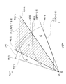
- It is a shift schedule figure which shows an example of the D range shift schedule used when performing shift control by a variator and a subtransmission mechanism by D range shift mode.
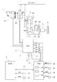
- It is a schematic block diagram which shows the cooperative control system of the transmission unit which is a control apparatus of Example 1, and an engine.
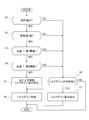
- 4 is a flowchart illustrating a flow of an oil temperature rise restriction failsafe control process executed by a failure diagnosis unit, a failsafe control unit, and an oil temperature rise restriction torque reduction control unit included in the transmission control module of the first embodiment.
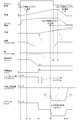
- 6 is a time chart showing characteristics at limp home when the first speed fixing of the subtransmission mechanism and the oil temperature rise restriction torque down control are executed based on the occurrence of a failure in the speed change control system of the variator during travel.
- the control device in the first embodiment is applied to an engine vehicle equipped with a continuously variable transmission AT / CVT (an example of an automatic transmission) with a sub-transmission having both a continuously variable transmission and a stepped transmission.
- AT / CVT an example of an automatic transmission
- sub-transmission having both a continuously variable transmission and a stepped transmission.
- the configuration of the first embodiment is divided into “overall system configuration”, “transmission control configuration by transmission unit”, “cooperative control system configuration of transmission and engine”, and “shift stage fixing and torque down control processing configuration”. I will explain.
- FIG. 1 shows a drive system and a control system of an engine vehicle equipped with a continuously variable transmission AT / CVT with an auxiliary transmission to which the control device of the first embodiment is applied.
- the overall system configuration will be described below with reference to FIG.
- the drive system of the engine vehicle includes an engine 1, a torque converter 2, a reduction gear pair 3, a transmission unit 4, a final reduction mechanism 5, and drive wheels 6.
- the continuously variable transmission AT / CVT with a sub-transmission is configured by incorporating a torque converter 2, a reduction gear pair 3, a transmission unit 4, and a final reduction mechanism 5 in a transmission case (not shown).
- the engine 1 can perform torque-down control that defines an upper limit of engine torque in response to an external torque-down request, in addition to engine torque control by the driver's accelerator operation.
- the engine 1 includes a torque control actuator 10 that performs torque down control by throttle valve opening / closing control, ignition timing retard control, and the like, and a starter motor 15 for starting the engine.
- the torque converter 2 is a three-element one-stage two-phase fluid transmission device that is disposed between the engine 1 and the reduction gear pair 3 and that exhibits a power transmission function, a torque fluctuation attenuation function, and a torque amplification function.
- the torque converter 2 includes a turbine runner 2a, a pump impeller 2b, a stator 2c, and a lockup clutch 2d.
- the turbine runner 2a is an input element to which power is input from the engine 1.
- the pump impeller 2b is an output element that transmits power to the output side where the transmission unit 4 having a frictional engagement element is disposed.
- the stator 2c is a torque amplifying element that is interposed between the turbine runner 2a and the pump impeller 2b that are disposed at positions facing each other, and is provided to a stationary member such as a case via a one-way clutch.
- the lock-up clutch 2d is disposed in the converter cover of the torque converter 2, and directly connects the turbine runner 2a of the torque converter 2 and the pump impeller 2b by clutch engagement.
- the reduction gear pair 3 is a reduction gear pair constituted by a small-diameter gear 3a that is rotationally driven by the output from the torque converter 2 and a large-diameter gear 3b that meshes with the small-diameter gear 3a and outputs to the transmission unit 4.
- the transmission unit 4 includes a variator 20 that is a belt-type continuously variable transmission mechanism, and an auxiliary transmission mechanism 30 that is provided in series with the variator 20.
- “provided in series” means that the variator 20 and the auxiliary transmission mechanism 30 are provided in series with each other in the power transmission path.
- the auxiliary transmission mechanism 30 may be directly connected to the output shaft of the variator 20 as in this example, or may be connected via another transmission or power transmission mechanism (for example, a gear train).
- the variator 20 is a belt-type continuously variable transmission mechanism including a primary pulley 21, a secondary pulley 22, and a pulley belt 23 that is stretched between the two pulleys 21 and 22.
- the two pulleys 21 and 22 are each arranged with a fixed conical plate, a sheave surface facing the fixed conical plate, and a movable conical plate forming a V-groove between the fixed conical plate,
- a primary pressure cylinder 23a and a secondary pressure cylinder 23b are provided on the back surface of the movable conical plate to displace the movable conical plate in the axial direction.
- the auxiliary transmission mechanism 30 is a stepped transmission mechanism with two forward speeds and one reverse speed.
- the auxiliary transmission mechanism 30 includes a Ravigneaux type planetary gear mechanism in which carriers of two planetary gears are connected, and friction engagement elements (low brake 32, high clutch 33, reverse brake 34).
- the low brake 32, the high clutch 33, and the reverse brake 34, which are friction engagement elements, are connected to a plurality of rotating elements that constitute the Ravigneaux type planetary gear mechanism, and change their linkage state.
- the final deceleration mechanism 5 is a mechanism that decelerates the output rotation from the transmission unit 4 and transmits it to the left and right drive wheels 6 and 6 while providing a differential function.
- the final speed reduction mechanism 5 is a speed reduction gear mechanism that includes an output gear 52 provided on the variator output shaft 41, an idler gear 53 and a reduction gear 54 provided on the idler shaft 50, and a final gear provided on the outer peripheral position of the differential case. And a gear 55.
- the differential gear mechanism includes a differential gear 56 interposed between the left and right drive shafts 51, 51.
- the engine vehicle control system includes a hydraulic control unit 7, a transmission control module 8 (abbreviated as “TCM”), and an engine control module 9 (abbreviated as “ECM”).
- TCM transmission control module 8
- ECM engine control module 9
- the transmission control module 8 and the engine control module 9 which are electronic control systems are connected by a CAN communication line 13 which can exchange information with each other.
- the hydraulic control unit 7 includes an oil pump 70 that is rotationally driven by the engine 1 that is a driving source for driving, and a valve control unit 71 (abbreviated as “VCU”) that adjusts various control pressures based on the discharge pressure from the oil pump 70. And).
- VCU valve control unit 71
- the line pressure PL, the primary pressure Ppri to the primary pressure cylinder 23a, and the secondary pressure Psec to the secondary pressure cylinder 23b are regulated.
- low brake pressure P (L / B) to the low brake 32, high clutch pressure P (H / C) to the high clutch 33, and reverse brake pressure P (R / B) to the reverse brake 34 Adjust pressure.
- the lockup differential pressure P (L / U) to the lockup clutch 2d is adjusted.
- the valve control unit 71 includes a line pressure solenoid valve 72, a primary pressure solenoid valve 73, and a secondary pressure solenoid valve 74. Furthermore, a low brake pressure solenoid valve 75, a high clutch pressure solenoid valve 76, a reverse brake pressure solenoid valve 77, and a lockup solenoid valve 78 are provided. Each solenoid valve 72, 73, 74, 75, 76, 77, 78 performs a pressure adjustment operation according to a control command value (indicated current) output from the transmission control module 8.
- the line pressure solenoid valve 72 adjusts the discharge pressure from the oil pump 70 to the commanded line pressure PL according to the line pressure command value output from the transmission control module 8.
- the line pressure PL is a source pressure when adjusting various control pressures, and is a hydraulic pressure that suppresses belt slip and clutch slip against torque transmitted through the drive system.
- the primary pressure solenoid valve 73 adjusts the pressure to the primary pressure Ppri commanded using the line pressure PL as the original pressure according to the primary pressure command value output from the transmission control module 8.
- the secondary pressure solenoid valve 74 adjusts the pressure to the secondary pressure Psec commanded using the line pressure PL as the original pressure in accordance with the secondary pressure command value output from the transmission control module 8.
- the low brake pressure solenoid valve 75 adjusts the low brake pressure P (L / B) to the commanded low brake pressure P (L / B) according to the low brake pressure command value output from the transmission control module 8 using the line pressure PL as the original pressure.
- the high clutch pressure solenoid valve 76 reduces the pressure to the high clutch pressure P (H / C) commanded using the line pressure PL as the original pressure in accordance with the high clutch pressure command value output from the transmission control module 8.
- the reverse brake pressure solenoid valve 77 adjusts the pressure to the reverse brake pressure P (R / B) commanded using the line pressure PL as the original pressure according to the reverse brake pressure command value output from the transmission control module 8.
- the lock-up solenoid valve 78 adjusts to a lock-up differential pressure P (L / U) for engaging / slipping / releasing the lock-up clutch 2d according to the command current output from the transmission control module 8.
- the transmission control module 8 performs line pressure control, variator control, auxiliary transmission control, lock-up control, and the like.
- line pressure control a command value for obtaining a target line pressure corresponding to the accelerator opening APO or the like is output to the line pressure solenoid valve 72.
- variator control when the target speed ratio (target primary speed Npri * ) is determined, a command value for obtaining the determined target speed ratio (target primary speed Npri * ) is output to the primary pressure solenoid valve 73 and the secondary pressure solenoid valve 74. To do.
- the command value for controlling the engagement / release of the low brake 32, the high clutch 33, and the reverse brake 34 according to the selected range position and the operating point (VSP, APO) on the shift schedule is solenoided. Output to valves 75, 76, 77.
- an instruction current for controlling the lockup differential pressure P (L / U) for engaging / slipping / releasing the lockup clutch 2d is output to the lockup solenoid valve 78.
- the transmission control module 8 receives information from a primary rotation sensor 90, a vehicle speed sensor 91, a secondary pressure sensor 92, an oil temperature sensor 93, an inhibitor switch 94, a brake switch 95, and a turbine rotation sensor 96. Furthermore, information from the secondary rotation sensor 97, the primary pressure sensor 98, and other sensors / switches 99 is input.
- the engine control module 9 receives sensor information from the engine rotation sensor 12, the accelerator opening sensor 14, and the like.
- the transmission control module 8 issues a request for information on the engine speed, the accelerator opening, and the engine torque to the engine control module 9, the engine speed Ne, the accelerator opening APO, and the estimated engine torque Te are transmitted via the CAN communication line 13.
- Receive information when a torque down request is issued from the transmission control module 8, the engine control module 9 that has received the torque down request via the CAN communication line 13 executes torque down control of the engine 1 according to the requested torque.
- FIG. 2 shows an example of the D range shift schedule used when the shift control by the variator 20 and the auxiliary transmission mechanism 30 is executed in the D range shift mode.
- the shift control configuration by the transmission unit will be described with reference to FIG.
- the “D-range shift schedule” includes an A region LRE based on a first-speed continuously variable transmission schedule when the sub-transmission mechanism 30 is at the first speed and a C-speed based on a second-speed continuously variable transmission schedule when the sub-transmission mechanism 30 is at the second speed. And a region HRE.
- the hatched area in FIG. 2 where the A area LRE and the C area HRE overlap each other is defined as a B area.
- the sub-transmission mechanism 30 is in the first gear and the variator 20 is the lowest gear ratio in the first-speed / lowest gear ratio line LL / L, and the sub-transmission mechanism 30 is in the first gear and the variator 20 is the highest gear.
- This is a continuously variable speed ratio region between the first speed and the highest speed ratio line LH / L.
- the sub-transmission mechanism 30 is in the second speed and the variator 20 is the lowest gear ratio in the second speed lowest speed ratio line HL / L, and the sub-transmission mechanism 30 is in the second speed and the variator 20 is in the highest speed.
- This is a continuously variable speed ratio region between the ratio and the second speed highest speed ratio line HH / L.
- the region B is a continuously variable transmission ratio region between the second speed lowest speed ratio line HL / L and the first speed highest gear ratio line LH / L.
- the up shift line MU / L for performing the 1 ⁇ 2 up shift of the sub-transmission mechanism 30 is set so as to substantially overlap the first speed highest gear ratio line LH / L.
- the down shift line MD / L for performing the 2 ⁇ 1 down shift of the auxiliary transmission mechanism 30 is set so as to substantially overlap the second speed lowest speed ratio line HL / L.
- a shift line is set for each accelerator opening APO, and the shift control is performed according to the shift line selected according to the accelerator opening APO and the vehicle speed VSP at that time.
- the “D range shift mode” is an automatic shift mode in which the gear ratio of the variator 20 and the gear position of the auxiliary transmission mechanism 30 are automatically changed according to the operating point (VSP, APO).
- the target primary rotational speed Npri * is determined by the operating point (VSP, APO) on the D range shift schedule of FIG. 2 specified by the vehicle speed VSP and the accelerator opening APO.
- the actual primary rotational speed Npri from the primary rotational sensor 90 is performed by the pulley hydraulic pressure feedback control that matches the target primary rotational speed Npri * .
- the gear ratio control of the variator 20 is executed when the sub-transmission mechanism 30 is held at the first speed or when the sub-transmission mechanism 30 is held at the second speed.
- the shift control of the subtransmission mechanism 30 is performed when the subtransmission mechanism 30 is in the first speed and the second speed is achieved when the operating point (VSP, APO) on the D range shift schedule in FIG. 2 crosses the up shift line MU / L. Upshift to stage.
- the sub-transmission mechanism 30 is in the second speed stage, when the operating point (VSP, APO) on the D range shift schedule in FIG. 2 crosses the down shift line MD / L, the downshift is performed to the first speed stage.
- a through-gear ratio of the transmission unit 4 (overall speed ratio obtained by multiplying the transmission ratio of the variator 20 by the transmission ratio of the subtransmission mechanism 30) is suddenly changed.
- the variator 20 and the subtransmission mechanism 30 are controlled so as to suppress this. That is, an appropriate target through speed ratio is set as a shift transient response during the upshift transition period and the downshift transition period of the auxiliary transmission mechanism 30.
- the gear ratio of the variator 20 is adjusted in accordance with the gear ratio transient characteristic of the subtransmission mechanism 30 so that the actual through gear ratio of the transmission unit 4 matches the target through gear ratio. Coordinated control is performed to control.
- FIG. 3 shows a cooperative control system of the transmission unit 4 and the engine 1 as the control device of the first embodiment.
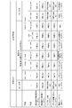
- FIG. 4 shows an oil temperature increase regulation torque down operation table based on the oil temperature condition and the vehicle speed condition in the continuously variable transmission AT / CVT with the auxiliary transmission according to the first embodiment.
- a cooperative control system configuration of the transmission unit 4 and the engine 1 will be described with reference to FIGS. 3 and 4.
- the drive system to be cooperatively controlled includes an engine 1 (driving drive source), a torque converter 2, a reduction gear pair 3, a transmission unit 4, a final reduction mechanism 5, and drive wheels. 6 are provided.
- Engine 1 drives oil pump 70.
- the torque converter 2 has a lock-up clutch 2d.
- the transmission unit 4 includes a variator 20 and an auxiliary transmission mechanism 30.
- the auxiliary transmission mechanism 30 includes a low brake 32, a high clutch 33, and a reverse brake 34.
- the cooperative control system of the transmission unit 4 and the engine 1 includes a hydraulic control unit 7, a transmission control module 8, and an engine control module 9, as shown in FIG.
- the valve control unit 71 of the hydraulic control unit 7 includes a line pressure solenoid valve 72, a primary pressure solenoid valve 73, and a secondary pressure solenoid valve 74. Further, a low brake pressure solenoid valve 75, a high clutch pressure solenoid valve 76, a reverse brake pressure solenoid valve 77, and a lockup solenoid valve 78 are provided.
- the transmission control module 8 includes a primary rotational speed Npri from the primary rotational sensor 90, a secondary rotational speed Nsec from the secondary rotational sensor 97, a vehicle speed VSP from the vehicle speed sensor 91, an oil temperature Temp from the oil temperature sensor 93, and the like. Enter.
- the engine control module 9 inputs the engine speed Ne from the engine speed sensor 12, the accelerator opening APO from the accelerator opening sensor 14, and the like.
- the transmission control module 8 and the engine control module 9 are connected via the CAN communication line 13 so that information can be exchanged.
- the transmission control module 8 includes a failure diagnosis unit 8a, a fail safe control unit 8b, and an oil temperature rise restriction torque down control unit 8c.
- the failure diagnosis unit 8a diagnoses whether or not a failure has occurred in the transmission control system of the variator 20 among the transmission control systems of the transmission unit 4.
- the shift control system failure of the variator 20 that performs the oil temperature rise restriction fail-safe control is: (a) Disconnection of primary rotation sensor 90 (b) Disconnection of secondary rotation sensor 97 (c) Disconnection of vehicle speed sensor 91 (d) Line pressure solenoid valve 72 disconnection, sky fault, ground fault, malfunction (e) The primary pressure solenoid valve 73 is disconnected, sky, ground, or malfunction.
- a failure in the speed change control system of the variator 20 is determined as a failure when a state exceeding the failure determination threshold is continued for a predetermined time. For example, if a state in which the actual variator ratio deviates from the target variator ratio and exceeds the failure determination threshold is continued for a predetermined time, the transmission control system failure of the variator 20 due to any of the above (a) to (e) is diagnosed.
- the fail-safe control unit 8b fixes the shift stage of the sub-transmission mechanism 30 to a predetermined shift stage when the failure of the shift control system of the variator 20 in the shift control system of the transmission unit 4 is confirmed, and also reduces the low speed of the variator 20. Limit shifting to the side.
- the gear position of the sub-transmission mechanism 30 is fixed to the first gear if the failure of the shift control system of the variator 20 is determined during traveling at the first speed.
- the failure of the shift control system of the variator 20 is determined during the second speed traveling, the second speed stage is maintained, and when the vehicle speed VSP becomes a predetermined vehicle speed or less, the sub speed mechanism 30 is fixed at the first speed stage. That is, the first-speed fixed fail-safe control is performed to fix the shift speed of the auxiliary transmission mechanism 30 to the first speed.
- the oil temperature rise restriction torque down control unit 8 c issues a torque down request for suppressing the torque of the engine 1 based on the oil temperature of the transmission hydraulic oil of the transmission unit 4.
- the first threshold Temp1 is set to be lower than the second threshold Temp2 when the shift stage is not fixed to the first speed stage.
- a torque down request is issued.
- the vehicle speed condition that the vehicle speed VSP is equal to or higher than the second threshold value VSP2 is added as a condition for issuing a torque reduction request to the engine control module 9, and the vehicle speed VSP is less than the second threshold value VSP2 even if the oil temperature condition is satisfied.
- the case where the gear stage is not fixed to the first gear stage is not only the case where the gear stage of the auxiliary transmission mechanism 30 is fixed to the second gear stage by the fail safe control, but the fail safe control is not executed. This includes the case where either the first gear or the second gear is selected as the gear position of the auxiliary transmission mechanism 30.
- the upper limit torque of the engine torque by the engine 1 is restricted to a torque that can be driven at a predetermined vehicle speed during limp home. Further, the ramp gradient is provided without changing the torque change characteristic stepwise when entering the control to reduce the engine torque to the upper limit torque and when the control is lost to return the engine torque from the upper limit torque to the default torque.
- abnormal refers to a failure diagnosis of the variator shift control system when the torque is reduced during high oil temperature control.
- Current means torque reduction during high oil temperature control before adding “torque down during high oil temperature control (abnormal)”.
- torque down at the time of abnormality and the current torque down are used together as the torque down at the time of high oil temperature control.
- the types of torque down control include “torque down during high oil temperature control (abnormal)”, “torque down during high oil temperature control (current)”, “torque down during limp home”, “ “Torque down according to clutch capacity”.
- “High oil temperature control (current) torque down” is when an abnormality occurs, the oil temperature condition is the second threshold Temp2 ⁇ the oil temperature Temp, and the vehicle speed condition is the first threshold VSP1 ⁇ the vehicle speed VSP Torque down is activated. Further, when it is normal and the oil temperature condition is the second threshold Temp2 ⁇ the oil temperature Temp, and the vehicle speed condition is the first threshold VSP1 ⁇ the vehicle speed VSP, the torque reduction is activated. Otherwise, torque down will not work. That is, “high oil temperature control (current) torque down” gives the same oil temperature condition and vehicle speed condition regardless of whether it is abnormal or normal.
- the “second threshold Temp2” is set to a threshold value that suppresses an increase in the oil temperature of the transmission hydraulic oil when the sub-shift stage is fixed at the second speed as fail-safe control.
- the “first threshold value VSP1” is set to a vehicle speed threshold value for determining that the vehicle is traveling.
- “High oil temperature control (abnormal) torque down” means that when the oil temperature condition is the first threshold Temp1 ⁇ the oil temperature Temp and the vehicle speed condition is the second threshold VSP2 ⁇ the vehicle speed VSP, the torque reduction is activated. To do. Further, when the oil temperature condition is the second threshold value Temp2 ⁇ the oil temperature Temp and the vehicle speed condition is the second threshold value VSP2 ⁇ the vehicle speed VSP, the torque reduction is activated. Otherwise, torque down will not work. In other words, in the case of “high oil temperature control (abnormal) torque down”, when it is abnormal, the oil temperature condition is made lower and the vehicle speed condition is made higher than “high oil temperature control (current) torque down”.
- first threshold Temp1 ( ⁇ second threshold Temp2) is set to a threshold for suppressing an increase in the oil temperature of the transmission hydraulic oil when the sub-speed is fixed at the first speed as fail-safe control.
- Second threshold Temp2 (> first threshold value VSP1)” is set to a vehicle speed threshold value that determines that the vehicle speed VSP has increased due to re-starting after the first speed is fixed by fail-safe control.
- the minimum torque down amount is selected as the final torque down amount among the plurality of torque down amounts as shown in FIG.
- the oil temperature condition is the first threshold Temp1 ⁇ the oil temperature Temp
- the limp home torque reduction is activated while the vehicle speed condition is the vehicle speed VSP ⁇ the second threshold VSP2.
- VSP2 the second threshold value
- torque reduction during high oil temperature control (during abnormality) ( ⁇ torque down during limp home) is activated.
- FIG. 5 shows the flow of the oil temperature rise restriction failsafe control process executed by the failure diagnosis unit 8a, the failsafe control unit 8b, and the oil temperature rise restriction torque down control unit 8c included in the transmission control module 8 of the first embodiment. Show. Hereinafter, each step of FIG. 5 will be described.
- step S1 following the start, the failure diagnosis unit 8a continues the state exceeding the failure determination threshold for a predetermined time to determine whether or not the failure determination of the shift control system of the variator 20 has been diagnosed. If YES (failure is confirmed), the process proceeds to step S2, and if NO (failure is not confirmed), the process proceeds to step S6.
- step S2 following the determination that the failure has been determined in step S1, it is determined whether or not the gear position of the subtransmission mechanism 30 is fixed to the first speed. If YES (first sub-speed), the process proceeds to step S3. If NO (second sub-speed), the process proceeds to step S6.
- step S3 it is determined whether or not the oil temperature Temp is equal to or higher than the first threshold Temp1 following the determination that the speed is the first sub-speed in step S2. If YES (oil temperature Temp ⁇ first threshold Temp1), the process proceeds to step S4. If NO (oil temperature Temp ⁇ first threshold Temp1), the process proceeds to step S6.
- step S4 following the determination that oil temperature Temp ⁇ first threshold Temp1 in step S3, it is determined whether or not the vehicle speed VSP is equal to or higher than the second threshold VSP2. If YES (vehicle speed VSP ⁇ second threshold value VSP2), the process proceeds to step S5. If NO (vehicle speed VSP ⁇ second threshold value VSP2), the process proceeds to step S6.
- step S5 following the determination that vehicle speed VSP ⁇ second threshold value VSP2 in step S4, an oil temperature rise restriction torque down amount is calculated based on torque down during high oil temperature control (during abnormality), and step S8. Proceed to
- step S6 following the determination of NO in S1, S2, S3, or S4, whether or not there is a torque-down operation based on the torque-down operation table, the oil temperature Temp, and the vehicle speed VSP shown in FIG. to decide. If YES (torque down operation is performed), the process proceeds to step S7, and if NO (torque down operation is not performed), the process proceeds to the end.
- step S7 following the determination in step S6 that the torque-down operation is present, a torque-down amount is calculated according to the torque-down operation mode, and the process proceeds to step S8.
- step S8 following the calculation of the oil temperature rise restriction torque down amount in step S5 or the calculation of the torque down amount in step S7, a torque down request for obtaining the calculated torque down amount is output, thereby reducing the torque.
- the minimum torque-down amount is selected as the final torque-down amount by MIN shift.
- the oil temperature of the transmission hydraulic oil increases in proportion to the increase in transmission input rotational speed and the increase in transmission input torque. Therefore, when the secondary transmission is fixed at the second speed, the input speed of the transmission is lower and the friction is smaller than in the case of the fixed at the first speed. Does not work.
- the automatic transmission is a transmission unit that combines a variator and a sub-transmission mechanism
- a failure occurs in the variator control system during traveling, and the variator transmission ratio at the time of the failure is on the high transmission ratio side.
- the gear ratio is fixed while maintaining the high gear ratio.
- the sub-transmission mechanism is fixed at the second speed, the total transmission ratio of the transmission unit remains at the high transmission ratio, and driving required for traveling in a traveling scene including a climbing road or the like at limp home. It is because there is a possibility that power cannot be secured.
- the present invention pays attention to the above-mentioned problems, and has set it as a solution to suppress an increase in the oil temperature of the transmission hydraulic fluid while ensuring the required driving force at the time of limp home.
- An oil temperature rise restriction torque down control unit 8c that issues a torque down request when the temperature condition is satisfied is employed.
- the oil temperature threshold when the shift speed is not fixed at the first speed is the second threshold Temp2
- the oil temperature threshold when the first speed is fixed is the first threshold Temp1
- Temp1 ⁇ Temp2 is a big and small relationship.
- the process proceeds from S1 to S2 in the flowchart of FIG. 5, and in S2, the shift stage of the subtransmission mechanism 30 is the first speed stage. Fixed to.
- the gear position of the subtransmission mechanism 30 is fixed at the first speed and the oil temperature condition (oil temperature Temp ⁇ first threshold Temp1) and the vehicle speed condition (vehicle speed VSP ⁇ second threshold VSP2) are satisfied, S2 to S3 ⁇
- the process proceeds from S4 to S5 to S8.
- the oil temperature rise restriction torque down amount is calculated based on the torque down during high oil temperature control (abnormal).
- a torque down request for obtaining the calculated oil temperature rise regulation torque reduction amount is output to the engine control module 9 to operate the torque down at the time of high oil temperature control (at the time of abnormality).
- the oil temperature rise restriction torque reduction is not activated until the vehicle speed condition (vehicle speed VSP ⁇ second threshold value VSP2) is satisfied.
- vehicle speed condition vehicle speed VSP ⁇ second threshold value VSP2
- priority is given to securing the driving force by the engine 1 over the suppression of the oil temperature rise of the transmission hydraulic oil. For this reason, it can suppress that driving force runs short in the re-start scene after fail safe control act
- FIG. 6 shows the respective characteristics at the time of limp home in which the first speed fixing of the subtransmission mechanism 30 and the oil temperature rise restriction torque down control are executed based on the occurrence of a shift control system failure of the variator 20 during traveling.
- the oil temperature rise suppressing action at the time of limp home will be described based on FIG.
- the abnormality detection timer starts operating based on a diagnosis that a failure has occurred in the speed change control system of the variator 20. Then, when time elapses in the abnormality detection state and the time t4 when the timer time reaches the set time, the failure is determined.
- the target variator ratio characteristic and the actual variator ratio characteristic surrounded by the arrow D in FIG. 6 show an example of failure detection in the transmission control system of the variator 20. That is, although the target variator ratio has changed to a small ratio (high-side gear ratio) slightly before time t2, the actual variator ratio has remained unchanged from time t1. For this reason, when the deviation width between the target variator ratio and the actual variator ratio exceeds the failure determination threshold at time t3, it is diagnosed that a failure has occurred in the transmission control system of the variator 20.
- the limp home torque down is activated by the limp home torque down amount.
- the increase in the vehicle speed VSP is suppressed, and the decrease in the vehicle speed VSP and the engine speed Ne starts from time t7.
- the engine control module 9 receives the request torque that returns to the default of torque down at limp home due to the ramp gradient (+ ⁇ ). Is output.
- the torque reduction operation suppresses the increase in oil temperature compared to the broken line characteristic, as shown by the oil temperature characteristic indicated by the solid line of arrow E in FIG. .
- the vehicle speed VSP becomes zero and the vehicle stops.
- Transmission control means for controlling (transmission control module 8).
- the transmission control means (transmission control module 8)
- An oil temperature rise restriction torque down control unit 8c that issues a torque down request for suppressing the torque of the driving source for driving (engine 1) based on the oil temperature of the transmission hydraulic oil of the automatic transmission (transmission unit 4).
- the oil temperature rise restriction torque down control unit 8c is not fixed to the first gear when the gear stage of the automatic transmission (sub transmission mechanism 30) is fixed to the first gear by the fail safe control unit 8b.
- a torque down request is issued.
- fail-safe control is permitted in which the fixed gear stage is set to the first gear stage in response to the driving force requirement at limp home.
- the torque-down control for restricting the oil temperature rise when the fixed speed is the first speed, the oil temperature is set to a lower oil temperature than when the speed is not fixed at the first speed, and the torque It is easy to enter the down operation.
- the oil temperature rise restriction torque down control unit 8c adds a vehicle speed condition that the vehicle speed VSP is equal to or higher than a threshold value (second threshold value VSP2) to the condition for issuing a torque reduction request. While it is less than the threshold value (second threshold value VSP2), no torque down request is issued. For this reason, it can suppress that driving force runs short in the re-start scene after fail safe control act
- the torque of the driving source for driving (engine 1) is limited to an upper limit torque that can be driven at a predetermined vehicle speed VSP during limp home. . For this reason, traveling at the predetermined vehicle speed VSP can be ensured at the time of limp home when the oil temperature rise restriction torque down control is activated. That is, in the oil temperature rise restriction torque down control, if the torque down amount is increased with emphasis on suppression of the oil temperature rise, traveling during limp home may not be ensured. On the other hand, if the amount of torque reduction is reduced with emphasis on ensuring travel during limp home, an increase in the oil temperature of the transmission hydraulic oil may not be suppressed. Therefore, the torque reduction amount of the driving source for driving (engine 1) is set so that the oil temperature rise suppression of the transmission hydraulic oil and the traveling ensuring during limp home are compatible.
- the oil temperature rise restriction torque down control unit 8c controls the torque of the travel drive source (engine 1) to the upper limit torque, and the torque of the travel drive source (engine 1) is the upper limit torque.
- a ramp gradient ( ⁇ ⁇ ) is provided in the torque change characteristic when the control is returned to the default torque. For this reason, it is possible to prevent a sudden torque change of the driving source for driving (engine 1) in the operation scene of the oil temperature rise restriction torque down control. In other words, the oil temperature rise restriction torque down control is unexpectedly executed during traveling due to the establishment of the oil temperature condition and the vehicle speed condition.
- the automatic transmission is a transmission unit 4 in which the variator 20 and the auxiliary transmission mechanism 30 are combined.
- the failure diagnosis unit 8a diagnoses whether a failure has occurred in the speed change control system of the variator 20, When the shift control system failure of the variator 20 is confirmed, the fail safe control unit 8b fixes the shift speed of the auxiliary transmission mechanism 30 to the first speed and restricts the shift of the variator 20 to the low side. For this reason, in the scene where the shift control system failure of the variator 20 is confirmed, the required driving force can be ensured at the time of limp home by fixing the shift stage of the auxiliary transmission mechanism 30 to the first speed.
- the sub-transmission mechanism 30 has first and second speed stages as gear stages.
- the fail safe control unit 8b fixes the speed stage of the auxiliary transmission mechanism 30 to the first speed and the speed change control system of the variator 20 fails during the second speed travel. Is determined, the second speed is maintained, and when the vehicle speed VSP becomes a predetermined vehicle speed or less, the gear position of the auxiliary transmission mechanism 30 is fixed to the first speed. For this reason, when a failure in the shift control system of the variator 20 is determined during the second speed traveling, it is possible to prevent a shift shock from being caused by a 2 ⁇ 1 downshift in the auxiliary transmission mechanism 30.
- Example 1 shows an example in which the control device of the present invention is applied to an engine vehicle equipped with a continuously variable transmission with an auxiliary transmission.
- the control device of the present invention may be applied to a vehicle equipped with an automatic transmission called step AT having a plurality of shift stages between a driving source for driving and driving wheels.
- the vehicle is not limited to an engine vehicle, and can also be applied to a hybrid vehicle equipped with an engine and a motor as a travel drive source, an electric vehicle equipped with a motor as a travel drive source, and the like.
Landscapes
- Engineering & Computer Science (AREA)
- General Engineering & Computer Science (AREA)
- Mechanical Engineering (AREA)
- Chemical & Material Sciences (AREA)
- Combustion & Propulsion (AREA)
- Transportation (AREA)
- Automation & Control Theory (AREA)
- Oil, Petroleum & Natural Gas (AREA)
- Control Of Transmission Device (AREA)
- Control Of Driving Devices And Active Controlling Of Vehicle (AREA)
- Control Of Vehicle Engines Or Engines For Specific Uses (AREA)
Abstract
複数の変速段を有する変速機ユニット(4)と変速機コントロールモジュール(8)を備え、変速機コントロールモジュール(8)は、故障診断部(8a)と、フェイルセーフ制御部(8b)と、油温上昇規制トルクダウン制御部(8c)と、を有する。フェイルセーフ制御部(8b)は、変速機ユニット(4)の変速制御系故障が確定すると、副変速機構(30)の変速段を所定の変速段に固定する。油温上昇規制トルクダウン制御部(8c)は、変速機ユニット4の変速機作動油の油温に基づいてエンジン(1)のトルクを抑えるトルクダウン要求を出す。そして、フェイルセーフ制御部(8b)によって副変速機構(30)の変速段が1速段に固定される場合、変速段が1速段に固定されていない場合の油温より低い油温に設定された油温条件が成立するとトルクダウン要求を出す。
Description
本発明は、車両に搭載される自動変速機の制御装置に関する。
従来、自動変速機の摩擦係合要素に対する供給油圧を検出する油圧スイッチを設け、正常時に同時にONすることのない複数の油圧スイッチが同時にONになることで油圧の異常を検出する。油圧の異常が検出されると(S1)、そのときの変速機の負荷が大きいときほどフェイルセーフ判断時間を短く設定する(S4,S5)。そして、前記油圧の異常状態が、前記フェイルセーフ判断時間以上継続したときに(S7)、変速段を固定するフェイルセーフ制御に移行させる(S8)車両用自動変速機のフェイルセーフ装置が知られている(例えば、特許文献1参照)。
上記特許文献1には、「異常発生時には、変速段を例えば3速に固定するなどのフェイルセーフ制御に移行させる。」と記載されている。これに対し、フェイルセーフ制御により自動変速機の変速段を固定してディラーや自宅等に向かって走行するリンプホーム時、走行するのに必要な駆動力を確保するため、固定先の変速段を低ギヤ段にしたいという要求がある。しかし、自動変速機の変速段を低ギヤ段に固定すると、変速機入力回転数が高くなってフリクションが大きくなるため、その跳ね返りとして変速機作動油の油温が上昇しやすくなってしまう、という問題がある。
本発明は、上記問題に着目してなされたもので、リンプホーム時、要求される駆動力を確保しつつ、変速機作動油の油温上昇を抑制することを目的とする。
上記目的を達成するため、本発明の自動変速機の制御装置は、走行用駆動源と駆動輪との間に搭載され、複数の変速段を有する自動変速機と、自動変速機を変速制御する変速機制御手段と、を備える。
変速機制御手段は、
自動変速機の変速制御系に故障が発生したかどうかを診断する故障診断部と、
自動変速機の変速制御系故障が確定すると、自動変速機の変速段を所定の変速段に固定するフェイルセーフ制御部と、
自動変速機の変速機作動油の油温上昇に基づいて走行用駆動源のトルクを抑えるトルクダウン要求を出す油温上昇規制トルクダウン制御部と、を有する。
油温上昇規制トルクダウン制御部は、フェイルセーフ制御部によって自動変速機の変速段が1速段に固定される場合、変速段が1速段に固定されていない場合の油温より低い油温に設定された油温条件が成立するとトルクダウン要求を出す。
変速機制御手段は、
自動変速機の変速制御系に故障が発生したかどうかを診断する故障診断部と、
自動変速機の変速制御系故障が確定すると、自動変速機の変速段を所定の変速段に固定するフェイルセーフ制御部と、
自動変速機の変速機作動油の油温上昇に基づいて走行用駆動源のトルクを抑えるトルクダウン要求を出す油温上昇規制トルクダウン制御部と、を有する。
油温上昇規制トルクダウン制御部は、フェイルセーフ制御部によって自動変速機の変速段が1速段に固定される場合、変速段が1速段に固定されていない場合の油温より低い油温に設定された油温条件が成立するとトルクダウン要求を出す。
このように、固定先の変速段を1速段とするフェイルセーフ制御を許容している。そして、固定先の変速段が1速段である場合、変速段が1速段に固定されていない場合よりも油温条件を低油温にし、トルクダウン作動に入り易くしている。この結果、リンプホーム時、要求される駆動力を確保しつつ、変速機作動油の油温上昇を抑制することができる。
以下、本発明の自動変速機の制御装置を実施するための形態を、図面に示す実施例1に基づいて説明する。
実施例1における制御装置は、無段変速と有段変速の両変速機能を備える副変速機付き無段変速機AT/CVT(自動変速機の一例)を搭載したエンジン車に適用したものである。以下、実施例1の構成を、「全体システム構成」、「変速機ユニットによる変速制御構成」、「変速とエンジンとの協調制御系構成」、「変速段固定及びトルクダウン制御処理構成」に分けて説明する。
[全体システム構成]
図1は、実施例1の制御装置が適用された副変速機付き無段変速機AT/CVTを搭載するエンジン車の駆動系及び制御系を示す。以下、図1に基づいて全体システム構成を説明する。
図1は、実施例1の制御装置が適用された副変速機付き無段変速機AT/CVTを搭載するエンジン車の駆動系及び制御系を示す。以下、図1に基づいて全体システム構成を説明する。
エンジン車の駆動系は、図1に示すように、エンジン1と、トルクコンバータ2と、リダクションギヤ対3と、変速機ユニット4と、終減速機構5と、駆動輪6と、を備えている。ここで、副変速機付き無段変速機AT/CVTは、トルクコンバータ2とリダクションギヤ対3と変速機ユニット4と終減速機構5を図外のトランスミッションケースに内蔵することにより構成される。
エンジン1は、ドライバのアクセル操作によるエンジントルク制御以外に、外部からのトルクダウン要求に応じてエンジントルクの上限を規定するトルクダウン制御が可能である。エンジン1には、スロットルバルブ開閉制御や点火時期リタード制御等によりトルクダウン制御を行うトルク制御アクチュエータ10と、エンジン始動用のスタータモータ15とを有する。
トルクコンバータ2は、エンジン1とリダクションギヤ対3との間に配され、動力伝達機能やトルク変動減衰機能やトルク増幅機能を発揮する3要素1段2相型の流体伝動装置である。このトルクコンバータ2は、タービンランナ2aと、ポンプインペラ2bと、ステータ2cと、ロックアップクラッチ2dと、を有する。
ここで、タービンランナ2aは、エンジン1から動力が入力される入力要素である。ポンプインペラ2bは、摩擦締結要素を有する変速機ユニット4が配された出力側に動力を伝達する出力要素である。ステータ2cは、互いに対向位置に配されたタービンランナ2aとポンプインペラ2bとの間に介装され、ケース等の静止部材に対してワンウェイクラッチを介して設けられるトルク増幅要素である。ロックアップクラッチ2dは、トルクコンバータ2のコンバータカバー内に配置され、クラッチ締結によってトルクコンバータ2のタービンランナ2aとポンプインペラ2bを直結する。
リダクションギヤ対3は、トルクコンバータ2からの出力により回転駆動する小径ギヤ3aと、小径ギヤ3aに噛み合い、変速機ユニット4へ出力する大径ギヤ3bと、によって構成される減速ギヤ対である。
変速機ユニット4は、ベルト式無段変速機構であるバリエータ20と、バリエータ20に対して直列に設けられる副変速機構30とを備える。ここで、「直列に設けられる」とは、動力伝達経路においてバリエータ20と副変速機構30が互いに直列の関係で設けられるという意味である。副変速機構30は、この例のようにバリエータ20の出力軸に直接接続されていてもよいし、その他の変速ないし動力伝達機構(例えば、ギヤ列)を介して接続されていてもよい。
バリエータ20は、プライマリプーリ21と、セカンダリプーリ22と、2つのプーリ21,22の間に掛け渡されるプーリベルト23と、を備えるベルト式無段変速機構である。2つのプーリ21,22は、それぞれ固定円錐板と、この固定円錐板に対してシーブ面を対向させた状態で配置され、固定円錐板との間にV溝を形成する可動円錐板と、この可動円錐板の背面に設けられて可動円錐板を軸方向に変位させるプライマリ圧シリンダ23aとセカンダリ圧シリンダ23bを備える。プライマリ圧シリンダ23aとセカンダリ圧シリンダ23bに供給される油圧を調整すると、V溝の幅が変化してプーリベルト23と2つのプーリ21,22との接触半径が変化し、バリエータ20の変速比が無段階に変化する。
副変速機構30は、前進2段・後進1段の有段変速機構である。副変速機構30は、2つの遊星歯車のキャリアを連結したラビニヨウ型遊星歯車機構と、摩擦締結要素(ローブレーキ32、ハイクラッチ33、リバースブレーキ34)と、を備える。摩擦締結要素であるローブレーキ32とハイクラッチ33とリバースブレーキ34は、ラビニヨウ型遊星歯車機構を構成する複数の回転要素に接続され、それらの連係状態を変更する。
副変速機構30の変速段は、各摩擦締結要素32~34への供給油圧を調整し、各摩擦締結要素32~34の締結・解放状態を切り替えると変更される。例えば、ローブレーキ32を締結し、ハイクラッチ33とリバースブレーキ34を解放すれば副変速機構30の変速段は前進1速段(ロー変速比)となる。ハイクラッチ33を締結し、ローブレーキ32とリバースブレーキ34を解放すれば副変速機構30の変速段は1速段よりも変速比が小さな前進2速段(変速比=1)となる。また、リバースブレーキ34を締結し、ローブレーキ32とハイクラッチ33を解放すれば副変速機構30の変速段は後退段となる。なお、副変速機構30のローブレーキ32とハイクラッチ33とリバースブレーキ34の全てを解放すれば、駆動輪6への駆動力伝達経路が遮断される。
終減速機構5は、変速機ユニット4からの出力回転を減速すると共に差動機能を与えて左右の駆動輪6,6に伝達する機構である。この終減速機構5は、減速ギヤ機構として、バリエータ出力軸41に設けられたアウトプットギヤ52と、アイドラ軸50に設けられたアイドラギヤ53及びリダクションギヤ54と、デフケースの外周位置に設けられたファイナルギヤ55と、を有する。そして、差動ギヤ機構として、左右のドライブ軸51,51の間に介装されたディファレンシャルギヤ56を有する。
エンジン車の制御系は、図1に示すように、油圧制御ユニット7と、変速機コントロールモジュール8(略称「TCM」)と、エンジンコントロールモジュール9(略称「ECM」)と、を備えている。電子制御系である変速機コントロールモジュール8とエンジンコントロールモジュール9は、互いの情報を交換可能なCAN通信線13により接続されている。
油圧制御ユニット7は、走行用駆動源であるエンジン1により回転駆動されるオイルポンプ70と、オイルポンプ70からの吐出圧に基づいて各種の制御圧を調圧するバルブコントロールユニット71(略称「VCU」)と、を備える。油圧制御ユニット7では、ライン圧PLと、プライマリ圧シリンダ23aへのプライマリ圧Ppriと、セカンダリ圧シリンダ23bへのセカンダリ圧Psecを調圧する。加えて、ローブレーキ32へのローブレーキ圧P(L/B)と、ハイクラッチ33へのハイクラッチ圧P(H/C)と、リバースブレーキ34へのリバースブレーキ圧P(R/B)を調圧する。さらに、ロックアップクラッチ2dへのロックアップ差圧P(L/U)を調圧する。
バルブコントロールユニット71には、ライン圧ソレノイド弁72と、プライマリ圧ソレノイド弁73と、セカンダリ圧ソレノイド弁74とを有する。さらに、ローブレーキ圧ソレノイド弁75と、ハイクラッチ圧ソレノイド弁76と、リバースブレーキ圧ソレノイド弁77と、ロックアップソレノイド弁78と、を有する。なお、各ソレノイド弁72,73,74,75,76,77,78は、変速機コントロールモジュール8から出力される制御指令値(指示電流)によって調圧動作を行う。
ライン圧ソレノイド弁72は、変速機コントロールモジュール8から出力されるライン圧指令値に応じ、オイルポンプ70からの吐出圧を、指令されたライン圧PLに調圧する。このライン圧PLは、各種の制御圧を調圧する際の元圧であり、駆動系を伝達するトルクに対してベルト滑りやクラッチ滑りを抑える油圧とされる。
プライマリ圧ソレノイド弁73は、変速機コントロールモジュール8から出力されるプライマリ圧指令値に応じ、ライン圧PLを元圧として指令されたプライマリ圧Ppriに減圧調整する。セカンダリ圧ソレノイド弁74は、変速機コントロールモジュール8から出力されるセカンダリ圧指令値に応じ、ライン圧PLを元圧として指令されたセカンダリ圧Psecに減圧調整する。
ローブレーキ圧ソレノイド弁75は、変速機コントロールモジュール8から出力されるローブレーキ圧指令値に応じ、ライン圧PLを元圧として指令されたローブレーキ圧P(L/B)に減圧調整する。ハイクラッチ圧ソレノイド弁76は、変速機コントロールモジュール8から出力されるハイクラッチ圧指令値に応じ、ライン圧PLを元圧として指令されたハイクラッチ圧P(H/C)に減圧調整する。リバースブレーキ圧ソレノイド弁77は、変速機コントロールモジュール8から出力されるリバースブレーキ圧指令値に応じ、ライン圧PLを元圧として指令されたリバースブレーキ圧P(R/B)に減圧調整する。
ロックアップソレノイド弁78は、変速機コントロールモジュール8から出力される指示電流に応じ、ロックアップクラッチ2dを締結/スリップ締結/解放するロックアップ差圧P(L/U)に調圧する。
変速機コントロールモジュール8は、ライン圧制御やバリエータ制御や副変速機制御やロックアップ制御、等を行う。ライン圧制御では、アクセル開度APO等に応じた目標ライン圧を得る指令値をライン圧ソレノイド弁72に出力する。バリエータ制御では、目標変速比(目標プライマリ回転数Npri*)を決めると、決めた目標変速比(目標プライマリ回転数Npri*)を得る指令値をプライマリ圧ソレノイド弁73及びセカンダリ圧ソレノイド弁74に出力する。
副変速機制御では、選択されているレンジ位置と変速スケジュール上での運転点(VSP,APO)に応じてローブレーキ32とハイクラッチ33とリバースブレーキ34の締結/解放を制御する指令値をソレノイド弁75,76,77へ出力する。ロックアップ制御では、ロックアップクラッチ2dを締結/スリップ締結/解放するロックアップ差圧P(L/U)を制御する指示電流をロックアップソレノイド弁78に出力する。
変速機コントロールモジュール8には、プライマリ回転センサ90、車速センサ91、セカンダリ圧センサ92、油温センサ93、インヒビタスイッチ94、ブレーキスイッチ95、タービン回転センサ96からの情報が入力される。さらに、セカンダリ回転センサ97、プライマリ圧センサ98、他のセンサ・スイッチ類99からの情報が入力される。
エンジンコントロールモジュール9には、エンジン回転センサ12、アクセル開度センサ14、等からのセンサ情報が入力される。変速機コントロールモジュール8は、エンジン回転数やアクセル開度やエンジントルクの情報要求をエンジンコントロールモジュール9へ出すと、CAN通信線13を介し、エンジン回転数Neやアクセル開度APOや推定エンジントルクTeの情報を受け取る。さらに、変速機コントロールモジュール8からトルクダウン要求を出すと、CAN通信線13を介してトルクダウン要求を受け取ったエンジンコントロールモジュール9では、リクエストトルクに応じたエンジン1のトルクダウン制御を実行する。
[変速機ユニットによる変速制御構成]
図2は、Dレンジ変速モードによりバリエータ20と副変速機構30による変速制御を実行する際に用いられるDレンジ変速スケジュールの一例を示す。以下、図2に基づいて変速機ユニットによる変速制御構成を説明する。
図2は、Dレンジ変速モードによりバリエータ20と副変速機構30による変速制御を実行する際に用いられるDレンジ変速スケジュールの一例を示す。以下、図2に基づいて変速機ユニットによる変速制御構成を説明する。
「Dレンジ変速スケジュール」は、副変速機構30が1速段のときの1速無段変速スケジュールによるA領域LREと、副変速機構30が2速段のときの2速無段変速スケジュールによるC領域HREと、を有する。なお、A領域LREとC領域HREとが互いに重なり合う領域である図2のハッチング領域をB領域とする。
A領域LREは、副変速機構30が1速段でバリエータ20が最Low変速比である1速最ロー変速比線LL/Lと、副変速機構30が1速段でバリエータ20が最High変速比である1速最ハイ変速比線LH/Lと、の間の無段変速比領域である。
C領域HREは、副変速機構30が2速段でバリエータ20が最Low変速比である2速最ロー変速比線HL/Lと、副変速機構30が2速段でバリエータ20が最High変速比である2速最ハイ変速比線HH/Lと、の間の無段変速比領域である。そして、B領域は、2速最ロー変速比線HL/Lと、1速最ハイ変速比線LH/Lと、の間の重なり合う無段変速比領域である。
Dレンジ変速スケジュールには、副変速機構30の1→2アップ変速を行うアップ変速線MU/Lが、1速最ハイ変速比線LH/L上に略重なるように設定されている。また、副変速機構30の2→1ダウン変速を行うダウン変速線MD/Lが、2速最ロー変速比線HL/L上に略重なるように設定されている。
なお、A領域LREとC領域HREには、アクセル開度APO毎に変速線が設定されており、変速制御は、アクセル開度APOに応じて選択される変速線と、そのときの車速VSPに従って行われる。図2には簡単のため、全負荷線F/L(アクセル開度APO=8/8のときの変速線)、パーシャル線P/L(アクセル開度APO=4/8のときの変速線)、コースト線C/L(アクセル開度APO=0のときの変速線)のみが示されている。
「Dレンジ変速モード」は、運転点(VSP,APO)に応じてバリエータ20の変速比と副変速機構30の変速段を自動的に変更する自動変速モードである。バリエータ20の変速比制御は、車速VSPとアクセル開度APOにより特定される図2のDレンジ変速スケジュール上での運転点(VSP,APO)により、目標プライマリ回転数Npri*を決める。そして、プライマリ回転センサ90からの実プライマリ回転数Npriを、目標プライマリ回転数Npri*に一致させるプーリ油圧のフィードバック制御により行われる。なお、バリエータ20の変速比制御は、副変速機構30が1速段に保持されているとき、又は、副変速機構30が2速段に保持されているときに実行される。
副変速機構30の変速制御は、副変速機構30が1速段のとき、図2のDレンジ変速スケジュール上での運転点(VSP,APO)がアップ変速線MU/Lを横切ると、2速段へアップシフトする。一方、副変速機構30が2速段のとき、図2のDレンジ変速スケジュール上での運転点(VSP,APO)がダウン変速線MD/Lを横切ると、1速段へダウンシフトする。
この副変速機構30でアップシフトやダウンシフトを実行するときは、変速機ユニット4のスルー変速比(バリエータ20の変速比に副変速機構30の変速比を掛けて得られる全体変速比)の急変を抑えるように、バリエータ20及び副変速機構30を制御する。即ち、副変速機構30のアップシフト過渡期とダウンシフト過渡期には、変速過渡応答として適切な目標スルー変速比が設定される。そして、バリエータ20の制御系が正常であるとき、変速機ユニット4の実スルー変速比が目標スルー変速比に一致するように、副変速機構30の変速比過渡特性に合わせてバリエータ20の変速比を制御する協調制御が行われる。
[変速機ユニットとエンジンとの協調制御系構成]
図3は、実施例1の制御装置としての変速機ユニット4とエンジン1との協調制御系を示す。図4は、実施例1の副変速機付き無段変速機AT/CVTにおいて油温条件と車速条件に基づく油温上昇規制トルクダウン作動表を示す。以下、図3及び図4に基づいて変速機ユニット4とエンジン1との協調制御系構成を説明する。
図3は、実施例1の制御装置としての変速機ユニット4とエンジン1との協調制御系を示す。図4は、実施例1の副変速機付き無段変速機AT/CVTにおいて油温条件と車速条件に基づく油温上昇規制トルクダウン作動表を示す。以下、図3及び図4に基づいて変速機ユニット4とエンジン1との協調制御系構成を説明する。
協調制御対象の駆動系は、図3に示すように、エンジン1(走行用駆動源)と、トルクコンバータ2と、リダクションギヤ対3と、変速機ユニット4と、終減速機構5と、駆動輪6と、を備えている。
エンジン1は、オイルポンプ70を駆動する。トルクコンバータ2は、ロックアップクラッチ2dを有する。変速機ユニット4は、バリエータ20と副変速機構30を有する。副変速機構30は、ローブレーキ32とハイクラッチ33とリバースブレーキ34を有する。
変速機ユニット4とエンジン1との協調制御系は、図3に示すように、油圧制御ユニット7と、変速機コントロールモジュール8と、エンジンコントロールモジュール9と、を備えている。
油圧制御ユニット7のバルブコントロールユニット71には、ライン圧ソレノイド弁72、プライマリ圧ソレノイド弁73、セカンダリ圧ソレノイド弁74を有する。さらに、ローブレーキ圧ソレノイド弁75、ハイクラッチ圧ソレノイド弁76、リバースブレーキ圧ソレノイド弁77、ロックアップソレノイド弁78を有する。
変速機コントロールモジュール8は、プライマリ回転センサ90からのプライマリ回転数Npriと、セカンダリ回転センサ97からのセカンダリ回転数Nsec、車速センサ91からの車速VSPと、油温センサ93からの油温Temp、等を入力する。
エンジンコントロールモジュール9は、エンジン回転センサ12からのエンジン回転数Neとアクセル開度センサ14からのアクセル開度APO、等を入力する。そして、変速機コントロールモジュール8とエンジンコントロールモジュール9は、CAN通信線13を介して情報交換が可能に接続されている。
変速機コントロールモジュール8は、故障診断部8aと、フェイルセーフ制御部8bと、油温上昇規制トルクダウン制御部8cと、を有する。
故障診断部8aは、変速機ユニット4の変速制御系のうち、バリエータ20の変速制御系に故障が発生したかどうかを診断する。
ここで、油温上昇規制フェイルセーフ制御を実行するバリエータ20の変速制御系故障とは、
(a) プライマリ回転センサ90の断線
(b) セカンダリ回転センサ97の断線
(c) 車速センサ91の断線
(d) ライン圧ソレノイド弁72の断線・天絡・地絡・機能異常
(e) プライマリ圧ソレノイド弁73の断線・天絡・地絡・機能異常
をいう。
(a) プライマリ回転センサ90の断線
(b) セカンダリ回転センサ97の断線
(c) 車速センサ91の断線
(d) ライン圧ソレノイド弁72の断線・天絡・地絡・機能異常
(e) プライマリ圧ソレノイド弁73の断線・天絡・地絡・機能異常
をいう。
そして、バリエータ20の変速制御系の故障は、故障判定閾値を超える状態を所定時間継続すると故障確定とされる。例えば、実バリエータ比が目標バリエータ比から故障判定閾値を超える乖離がある状態を所定時間継続すると、上記(a)~(e)の何れかによるバリエータ20の変速制御系故障と診断する。
フェイルセーフ制御部8bは、変速機ユニット4の変速制御系のうち、バリエータ20の変速制御系故障が確定すると、副変速機構30の変速段を所定の変速段に固定すると共に、バリエータ20のロー側への変速を制限する。
ここで、副変速機構30の変速段は、1速走行中にバリエータ20の変速制御系の故障が確定すると、副変速機構30の変速段を1速固定にする。2速走行中にバリエータ20の変速制御系の故障が確定すると2速段を保持し、車速VSPが所定車速以下になった場合に副変速機構30の変速段を1速固定にする。即ち、副変速機構30の変速段を1速段に固定する1速固定のフェイルセーフ制御を行う。
ちなみに、副変速機2速固定のフェイルセーフ制御では、1速走行中にバリエータの変速制御系の故障が確定すると1速段を保持し、停車後に変速段を副変速機2速固定にする。2速走行中にバリエータの変速制御系の故障が確定すると副変速機2速固定にする。なお、1速固定のフェイルセーフ制御と副変速機2速固定のフェイルセーフ制御は、何れかのフェイルセーフ制御を選択可能としても良い。
油温上昇規制トルクダウン制御部8cは、変速機ユニット4の変速機作動油の油温に基づいてエンジン1のトルクを抑えるトルクダウン要求を出す。このとき、フェイルセーフ制御部8bによって副変速機構30の変速段が1速段に固定される場合、変速段が1速段に固定されていない場合の第2閾値Temp2より低い第1閾値Temp1に設定された油温条件が成立するとトルクダウン要求を出す。そして、エンジンコントロールモジュール9に対してトルクダウン要求を出す条件には、車速VSPが第2閾値VSP2以上という車速条件を加え、油温条件が成立しても車速VSPが第2閾値VSP2未満である間はトルクダウン要求を出さない。ここで、変速段が1速段に固定されていない場合とは、フェイルセーフ制御によって副変速機構30の変速段が2速段に固定される場合だけでなく、フェイルセーフ制御が実行されず、副変速機構30の変速段として1速段や2速段の何れかが選択される場合も含む。
油温上昇規制トルクダウン制御部8cからトルクダウン要求を出すとき、エンジン1によるエンジントルクの上限トルクを、リンプホーム時に所定の車速により走行可能なトルクに規制する。さらに、エンジントルクを上限トルクまで低下させる制御入り時、及び、エンジントルクを上限トルクからデフォルトトルクに復帰させる制御抜け時、トルク変化特性をステップ的に変化させないでランプ勾配を設ける。
副変速機付き無段変速機AT/CVTにおいて、油温条件と車速条件に基づく油温上昇規制トルクダウンの作動を図4に基づいて説明する。なお、「異常時」とは、高油温制御時トルクダウンでのバリエータ変速制御系の故障診断時のことをいう。「現行」とは、「高油温制御時(異常時)トルクダウン」を追加する前の高油温制御時トルクダウンをいう。この例では、高油温制御時トルクダウンとして、異常時のトルクダウンと現行のトルクダウンを併用している。
トルクダウン制御の種別として、図4に示すように、「高油温制御時(異常時)トルクダウン」、「高油温制御時(現行)トルクダウン」、「リンプホーム時トルクダウン」、「クラッチ容量に応じたトルクダウン」を備える。
「リンプホーム時トルクダウン」及び「クラッチ容量に応じたトルクダウン」については、異常時(副変速1速固定かつSOL OFF指示)の場合、油温条件と車速条件にかかわらずトルクダウンが作動する。そして、異常時以外の場合、トルクダウンが作動する場合がある。
「高油温制御時(現行)トルクダウン」は、異常時であって、油温条件が第2閾値Temp2≦油温Tempであり、かつ、車速条件が第1閾値VSP1≦車速VSPであるとき、トルクダウンが作動する。また、正常時であって、油温条件が第2閾値Temp2≦油温Tempであり、かつ、車速条件が第1閾値VSP1≦車速VSPであるとき、トルクダウンが作動する。それ以外の場合、トルクダウンが作動しない。つまり、「高油温制御時(現行)トルクダウン」は、異常時か正常時かにかかわらず、同じ油温条件と車速条件が与えられる。
ここで、「第2閾値Temp2」は、フェイルセーフ制御として副変速段を2速固定にした場合に変速機作動油の油温の上昇を抑える閾値に設定される。「第1閾値VSP1」は、走行中であることを判定する車速閾値に設定される。
「高油温制御時(異常時)トルクダウン」は、油温条件が第1閾値Temp1≦油温Tempであり、かつ、車速条件が第2閾値VSP2≦車速VSPであるとき、トルクダウンが作動する。また、異常時であって、油温条件が第2閾値Temp2≦油温Tempであり、かつ、車速条件が第2閾値VSP2≦車速VSPであるとき、トルクダウンが作動する。それ以外の場合、トルクダウンが作動しない。つまり、「高油温制御時(異常時)トルクダウン」は、異常時であるとき、「高油温制御時(現行)トルクダウン」よりも油温条件が低くされ、車速条件が高くされる。
ここで、「第1閾値Temp1(<第2閾値Temp2)」は、フェイルセーフ制御として副変速段を1速固定にした場合に変速機作動油の油温の上昇を抑える閾値に設定される。「第2閾値VSP2(>第1閾値VSP1)」は、フェイルセーフ制御により1速固定した後、再発進によって車速VSPが上昇したことを判定する車速閾値に設定される。
そして、トルクダウンが作動する種別が複数存在する場合、図4に示すように、複数のトルクダウン量のうち、最小値のトルクダウン量が最終トルクダウン量として選択される(MINどり)。例えば、異常時、油温条件が第1閾値Temp1≦油温Tempであるが、車速条件が車速VSP<第2閾値VSP2である間は、リンプホーム時トルクダウンが作動する。そして、車速VSPが上昇し、車速条件が第2閾値VSP2≦車速VSPになると、高油温制御時(異常時)トルクダウン(<リンプホーム時トルクダウン)が作動する。
[油温上昇規制フェイルセーフ制御処理構成]
図5は、実施例1の変速機コントロールモジュール8に有する故障診断部8aとフェイルセーフ制御部8bと油温上昇規制トルクダウン制御部8cで実行される油温上昇規制フェイルセーフ制御処理の流れを示す。以下、図5の各ステップについて説明する。
図5は、実施例1の変速機コントロールモジュール8に有する故障診断部8aとフェイルセーフ制御部8bと油温上昇規制トルクダウン制御部8cで実行される油温上昇規制フェイルセーフ制御処理の流れを示す。以下、図5の各ステップについて説明する。
ステップS1では、スタートに続き、故障診断部8aにおいて、故障判定閾値を超える状態を所定時間継続することにより、バリエータ20の変速制御系の故障確定を診断したか否かを判断する。YES(故障確定)の場合はステップS2へ進み、NO(故障不確定)の場合はステップS6へ進む。
ステップS2では、ステップS1での故障確定であるとの判断に続き、副変速機構30の変速段が1速固定であるか否かを判断する。YES(副変速1速)の場合はステップS3へ進み、NO(副変速2速)の場合はステップS6へ進む。
ステップS3では、ステップS2での副変速1速であるとの判断に続き、油温Tempが第1閾値Temp1以上であるか否かを判断する。YES(油温Temp≧第1閾値Temp1)の場合はステップS4へ進み、NO(油温Temp<第1閾値Temp1)の場合はステップS6へ進む。
ステップS4では、ステップS3での油温Temp≧第1閾値Temp1であるとの判断に続き、車速VSPが第2閾値VSP2以上であるか否かを判断する。YES(車速VSP≧第2閾値VSP2)の場合はステップS5へ進み、NO(車速VSP<第2閾値VSP2)の場合はステップS6へ進む。
ステップS5では、ステップS4での車速VSP≧第2閾値VSP2であるとの判断に続き、高油温制御時(異常時)トルクダウンに基づいて油温上昇規制トルクダウン量を算出し、ステップS8へ進む。
ステップS6では、S1又はS2又はS3又はS4でのNOであるとの判断に続き、図4に示すトルクダウン作動表と油温Tempと車速VSPに基づいて、トルクダウンの作動有りか否かを判断する。YES(トルクダウンの作動有り)の場合はステップS7へ進み、NO(トルクダウンの作動無し)の場合はエンドへ進む。
ステップS7では、ステップS6でのトルクダウンの作動有りとの判断に続き、トルクダウン作動態様に応じてトルクダウン量を算出し、ステップS8へ進む。
ステップS8では、ステップS5での油温上昇規制トルクダウン量の算出、或いは、ステップS7でのトルクダウン量の算出に続き、算出されたトルクダウン量を得るトルクダウン要求を出力することでトルクダウンを作動し、エンドへ進む。
ここで、複数のトルクダウン量が算出される場合は、MINどりによって最小値のトルクダウン量が最終トルクダウン量として選択される。
ここで、複数のトルクダウン量が算出される場合は、MINどりによって最小値のトルクダウン量が最終トルクダウン量として選択される。
次に、実施例1の作用を、「油温上昇規制フェイルセーフ制御作用」、「リンプホーム時の油温上昇抑制作用」に分けて説明する。
[油温上昇規制フェイルセーフ制御作用]
まず、異常時であるか正常時であるかにかかわらず、油温条件が第2閾値Temp2≦油温Tempであり、かつ、車速条件が第1閾値VSP1≦車速VSPであるとき、高油温制御時トルクダウンが作動するものを比較例とする。
まず、異常時であるか正常時であるかにかかわらず、油温条件が第2閾値Temp2≦油温Tempであり、かつ、車速条件が第1閾値VSP1≦車速VSPであるとき、高油温制御時トルクダウンが作動するものを比較例とする。
この比較例の場合、フェイルセーフ制御により副変速機2速固定にするときは、変速機作動油の油温が第2閾値Temp2になってからトルクダウンを作動させても変速機作動油の油温上昇を抑えることができる。
即ち、変速機作動油の油温は、変速機入力回転数の上昇と変速機入力トルクの上昇に比例して上昇する。よって、副変速機2速固定にすると、1速固定の場合に比べて変速機入力回転数が低くてフリクションも小さいことにより、元々副変速機2速固定は高い油温となりにくく、トルクダウンが作動しない。
これに対し、フェイルセーフ制御により副変速機構の変速段を固定してディラーや自宅等に向かって走行するリンプホーム時、走行するのに必要な駆動力を確保するため、固定先の変速段を1速段にしたいという要求がある。特に、自動変速機が、バリエータと副変速機構を組み合わせた変速機ユニットの場合には、走行中にバリエータの制御系に故障が発生し、故障発生時のバリエータ変速比がハイ変速比側であると、ハイ変速比のままで変速比が固定される。このとき、副変速機構を2速固定にすると、変速機ユニットのトータル変速比がハイ変速比になったままとなり、リンプホーム時、登坂路等を含む走行シーンにおいて、走行するのに必要な駆動力を確保できないおそれがあることによる。
しかし、副変速機構の変速段を1速固定にすると、副変速機2速固定の場合に比べ変速機入力回転数が高くなってフリクションが大きくなるため、その跳ね返りとして変速機作動油の油温が上昇しやすくなってしまう、という新たな問題が発生することを知見した。
本発明等は、上記知見した問題点に着目し、リンプホーム時、要求される駆動力を確保しつつ、変速機作動油の油温上昇を抑制することを解決課題とした。この課題を解決するため、フェイルセーフ制御部8bによって副変速機構30が1速固定にされる場合、変速段が1速段に固定されていない場合の油温より低い油温に設定された油温条件が成立するとトルクダウン要求を出す油温上昇規制トルクダウン制御部8cを採用した。
ここで、変速段が1速段に固定されていない場合の油温閾値は第2閾値Temp2であるのに対し、1速固定にされる場合の油温閾値は第1閾値Temp1であり、Temp1<Temp2という大小関係にある。
即ち、バリエータ20の制御系に故障が発生し、バリエータ20の制御系故障が確定すると、図5のフローチャートにおいて、S1→S2へと進み、S2では、副変速機構30の変速段が1速段に固定される。そして、副変速機構30の変速段が1速段に固定され、油温条件(油温Temp≧第1閾値Temp1)と車速条件(車速VSP≧第2閾値VSP2)が成立すると、S2からS3→S4→S5→S8へと進む。S5では、高油温制御時(異常時)トルクダウンに基づいて油温上昇規制トルクダウン量が算出される。次のS8では、算出された油温上昇規制トルクダウン量を得るトルクダウン要求をエンジンコントロールモジュール9へ出力することで高油温制御時(異常時)トルクダウンが作動する。
このように、バリエータ20の制御系故障が確定すると、制御系として正常である副変速機構30での変速段を1速固定にするフェイルセーフ制御を許容している。このため、ディラーや自宅等に向かって走行するリンプホーム時、要求される駆動力が確保される。そして、副変速機構30での固定先の変速段が1速段である場合、変速段が1速段に固定されていない場合よりも油温条件を低油温にし、トルクダウン作動に入り易くしている。このため、副変速機2速固定の場合等に比べ早期に開始されるエンジン1のトルクダウン作動により、変速機入力トルクが低く抑えられることで、変速機入力回転数が低く抑えられ、変速機作動油の油温上昇が規制される。この結果、リンプホーム時、要求される駆動力を確保しつつ、変速機作動油の油温上昇を抑制することができる。
但し、副変速機構30の変速段が1速段に固定され、油温条件(油温Temp≧第1閾値Temp1)が成立しても、車速条件(車速VSP≧第2閾値VSP2)が不成立である間は、図5のフローチャートにおいて、S2からS3→S4→S6→S7→S8へと進む。S7では、リンプホーム時トルクダウン量が算出される。次のS8では、算出されたリンプホーム時トルクダウン量を得るトルクダウン要求をエンジンコントロールモジュール9へ出力することでリンプホーム時トルクダウンが作動する。なお、リンプホーム時トルクダウン量<油温上昇規制トルクダウン量という大小関係がある。
このように、フェイルセーフ制御が作動した後の再発進時においては、車速条件(車速VSP≧第2閾値VSP2)が成立するまでは、油温上昇規制トルクダウンを作動させないようにしている。このように、車速条件(車速VSP≧第2閾値VSP2)が成立するまでは、変速機作動油の油温上昇抑制よりもエンジン1による駆動力の確保を優先する。このため、フェイルセーフ制御が作動した後の再発進シーンにおいて、駆動力が不足することを抑制することができる。
[リンプホーム時の油温上昇抑制作用]
図6は、走行中のバリエータ20の変速制御系故障の発生に基づいて副変速機構30の1速固定及び油温上昇規制トルクダウン制御が実行されるリンプホーム時における各特性を示す。以下、図6に基づいてリンプホーム時の油温上昇抑制作用を説明する。
図6は、走行中のバリエータ20の変速制御系故障の発生に基づいて副変速機構30の1速固定及び油温上昇規制トルクダウン制御が実行されるリンプホーム時における各特性を示す。以下、図6に基づいてリンプホーム時の油温上昇抑制作用を説明する。
時刻t1にてアクセル踏み込み操作により発進すると、時刻t2にて車速VSPが油温上昇規制トルクダウン入り車速(=第1閾値VSP1)になる。その後、時刻t3にてバリエータ20の変速制御系に故障が発生したとの診断に基づいて異常検知タイマーが作動を開始する。そして、異常検知状態のままで時間が経過し、タイマー時間が設定時間に到達する時刻t4になると故障確定とされる。
ここで、図6の矢印Dで囲まれる目標バリエータ比特性と実バリエータ比特性は、バリエータ20の変速制御系における故障検知例を示す。つまり、目標バリエータ比が時刻t2の少し前から小さい比(ハイ側変速比)に変化しているにもかかわらず、実バリエータ比は時刻t1から変化することなく推移している。このため、時刻t3にて目標バリエータ比と実バリエータ比の乖離幅が故障判定閾値を超えることで、バリエータ20の変速制御系に故障が発生したと診断する。そして、目標バリエータ比と実バリエータ比の乖離幅が故障判定閾値を超えたままで、時刻t3~t4までの継続時間を経過すると、時刻t4にてバリエータ20の変速制御系故障が確定とされる。これによって、時刻t4からは副変速機構30が1速固定とされる。
時刻t4~時刻t5までは、油温Tempが第1閾値Temp1未満で油温条件が成立しないため、リンプホーム時トルクダウン量によるリンプホーム時トルクダウンが作動する。そして、時刻t5になると、油温Tempが第1閾値Temp1(=油温上昇規制トルクダウン入り油温)以上という油温条件が成立するため、リンプホーム時トルクダウンの作動から高油温制御時(異常時)トルクダウンの作動へと移行する。
時刻t5になると、ランプ勾配(-θ)によるトルクダウン要求(=リクエストトルク)がエンジンコントロールモジュール9へ出力される。時刻t6にてアクセル足離し操作によりコースト走行に入ると、車速VSPの上昇が抑えられ、時刻t7から車速VSPとエンジン回転数Neの低下を開始する。
時刻t8にて車速VSPが油温上昇規制トルクダウン抜け車速(=第2閾値VSP2)まで低下すると、ランプ勾配(+θ)によりリンプホーム時トルクダウンのデフォルトまで復帰するリクエストトルクがエンジンコントロールモジュール9へ出力される。この時刻t5~t8までの高油温制御時(異常時)トルクダウンの作動により、図8の矢印Eの実線による油温特性に示すように、油温の上昇が破線特性に比べて抑えられる。そして、時刻t9にて車速VSPがゼロとなって停車する。
このように、高油温制御時(異常時)トルクダウンでは、エンジン1のトルクを上限トルクまで制限する制御入り時、及び、上限トルクからデフォルトトルクに復帰させる制御抜け時、トルク変化特性にランプ勾配(±θ)を設けるようにしている。このため、高油温制御時(異常時)トルクダウンの制御開始時、及び、制御終了時にエンジントルクの急変が抑えられる。
以上説明したように、実施例1の副変速機付き無段変速機AT/CVTの制御装置にあっては、下記に列挙する効果が得られる。
(1) 走行用駆動源(エンジン1)と駆動輪6との間に搭載され、複数の変速段を有する自動変速機(変速機ユニット4)と、自動変速機(変速機ユニット4)を変速制御する変速機制御手段(変速機コントロールモジュール8)と、を備える。
この自動変速機(副変速機付き無段変速機AT/CVT)の制御装置において、
変速機制御手段(変速機コントロールモジュール8)は、
自動変速機(変速機ユニット4)の変速制御系に故障が発生したかどうかを診断する故障診断部8aと、
自動変速機(変速機ユニット4)の変速制御系故障が確定すると、自動変速機(副変速機構30)の変速段を所定の変速段に固定するフェイルセーフ制御部8bと、
自動変速機(変速機ユニット4)の変速機作動油の油温に基づいて走行用駆動源(エンジン1)のトルクを抑えるトルクダウン要求を出す油温上昇規制トルクダウン制御部8cと、を有し、
油温上昇規制トルクダウン制御部8cは、フェイルセーフ制御部8bによって自動変速機(副変速機構30)の変速段が1速段に固定される場合、変速段が1速段に固定されていない場合の油温より低い油温に設定された油温条件が成立するとトルクダウン要求を出す。
このため、リンプホーム時、要求される駆動力を確保しつつ、変速機作動油の油温上昇を抑制することができる。
即ち、リンプホーム時の駆動力要求に対して固定先の変速段を1速段とするフェイルセーフ制御を許容している。そして、油温上昇を規制するトルクダウン制御において、固定先の変速段が1速段である場合、変速段が1速段に固定されていない場合よりも油温条件を低油温にし、トルクダウン作動に入り易くしている。
この自動変速機(副変速機付き無段変速機AT/CVT)の制御装置において、
変速機制御手段(変速機コントロールモジュール8)は、
自動変速機(変速機ユニット4)の変速制御系に故障が発生したかどうかを診断する故障診断部8aと、
自動変速機(変速機ユニット4)の変速制御系故障が確定すると、自動変速機(副変速機構30)の変速段を所定の変速段に固定するフェイルセーフ制御部8bと、
自動変速機(変速機ユニット4)の変速機作動油の油温に基づいて走行用駆動源(エンジン1)のトルクを抑えるトルクダウン要求を出す油温上昇規制トルクダウン制御部8cと、を有し、
油温上昇規制トルクダウン制御部8cは、フェイルセーフ制御部8bによって自動変速機(副変速機構30)の変速段が1速段に固定される場合、変速段が1速段に固定されていない場合の油温より低い油温に設定された油温条件が成立するとトルクダウン要求を出す。
このため、リンプホーム時、要求される駆動力を確保しつつ、変速機作動油の油温上昇を抑制することができる。
即ち、リンプホーム時の駆動力要求に対して固定先の変速段を1速段とするフェイルセーフ制御を許容している。そして、油温上昇を規制するトルクダウン制御において、固定先の変速段が1速段である場合、変速段が1速段に固定されていない場合よりも油温条件を低油温にし、トルクダウン作動に入り易くしている。
(2) 油温上昇規制トルクダウン制御部8cは、トルクダウン要求を出す条件に、車速VSPが閾値(第2閾値VSP2)以上という車速条件を加え、油温条件が成立しても車速VSPが閾値(第2閾値VSP2)未満である間はトルクダウン要求を出さない。
このため、フェイルセーフ制御が作動した後の再発進シーンにおいて、駆動力が不足することを抑制することができる。
即ち、車両の発進時は車両走行中に比べ大きな駆動力を要する。この点に着目し、発進車速域を脱するまでの短い時間に限っては、例外として、変速機作動油の油温上昇抑制よりも走行用駆動源(エンジン1)による駆動力確保を優先している。
このため、フェイルセーフ制御が作動した後の再発進シーンにおいて、駆動力が不足することを抑制することができる。
即ち、車両の発進時は車両走行中に比べ大きな駆動力を要する。この点に着目し、発進車速域を脱するまでの短い時間に限っては、例外として、変速機作動油の油温上昇抑制よりも走行用駆動源(エンジン1)による駆動力確保を優先している。
(3) 油温上昇規制トルクダウン制御部8cは、トルクダウン要求を出すとき、走行用駆動源(エンジン1)のトルクを、リンプホーム時に所定の車速VSPにより走行可能な上限トルクまでに制限する。
このため、油温上昇規制トルクダウン制御が作動するリンプホーム時において、所定の車速VSPによる走行を確保することができる。
即ち、油温上昇規制トルクダウン制御において、油温上昇抑制を重視してトルクダウン量を大きくすると、リンプホーム時の走行が確保できないことがある。一方、リンプホーム時の走行確保を重視してトルクダウン量を小さくすると、変速機作動油の油温上昇を抑制できないことがある。そこで、変速機作動油の油温上昇抑制と、リンプホーム時の走行確保と、が両立する走行用駆動源(エンジン1)のトルクダウン量に設定している。
このため、油温上昇規制トルクダウン制御が作動するリンプホーム時において、所定の車速VSPによる走行を確保することができる。
即ち、油温上昇規制トルクダウン制御において、油温上昇抑制を重視してトルクダウン量を大きくすると、リンプホーム時の走行が確保できないことがある。一方、リンプホーム時の走行確保を重視してトルクダウン量を小さくすると、変速機作動油の油温上昇を抑制できないことがある。そこで、変速機作動油の油温上昇抑制と、リンプホーム時の走行確保と、が両立する走行用駆動源(エンジン1)のトルクダウン量に設定している。
(4) 油温上昇規制トルクダウン制御部8cは、走行用駆動源(エンジン1)のトルクを上限トルクまでに制限する制御入り時、及び、走行用駆動源(エンジン1)のトルクを上限トルクからデフォルトトルクに復帰させる制御抜け時、トルク変化特性にランプ勾配(±θ)を設ける。
このため、油温上昇規制トルクダウン制御の作動シーンにおいて、走行用駆動源(エンジン1)のトルク急変を防止することができる。
即ち、油温上昇規制トルクダウン制御は、走行中、油温条件と車速条件の成立により不意に実行される。よって、変速との協調制御等のように応答性が問われるトルクダウン制御のようにステップ的にトルクが変化する上限トルク特性により制限すると、走行用駆動源(エンジン1)のトルクが急変し、乗員に違和感を与えることがある。
このため、油温上昇規制トルクダウン制御の作動シーンにおいて、走行用駆動源(エンジン1)のトルク急変を防止することができる。
即ち、油温上昇規制トルクダウン制御は、走行中、油温条件と車速条件の成立により不意に実行される。よって、変速との協調制御等のように応答性が問われるトルクダウン制御のようにステップ的にトルクが変化する上限トルク特性により制限すると、走行用駆動源(エンジン1)のトルクが急変し、乗員に違和感を与えることがある。
(5) 自動変速機は、バリエータ20と副変速機構30を組み合わせた変速機ユニット4であり、
故障診断部8aは、バリエータ20の変速制御系に故障が発生したかどうかを診断し、
フェイルセーフ制御部8bは、バリエータ20の変速制御系故障が確定すると、副変速機構30の変速段を1速固定にすると共に、バリエータ20のロー側への変速を制限する。
このため、バリエータ20の変速制御系故障が確定したシーンにおいて、副変速機構30の変速段を1速固定にすることで、リンプホーム時、要求される駆動力を確保することができる。
即ち、変速機ユニット4の場合、バリエータ20の変速制御系故障が確定すると、バリエータ20のロー側への変速が制限されるため、フェイルセーフ制御を2速固定にすると、リンプホーム時に要求される駆動力を確保することが困難になる場合がある。しかし、正常な副変速機構30の制御系を用い、副変速機構30の変速段を1速固定にすることで、リンプホーム時に要求される駆動力を確保することが可能である。
故障診断部8aは、バリエータ20の変速制御系に故障が発生したかどうかを診断し、
フェイルセーフ制御部8bは、バリエータ20の変速制御系故障が確定すると、副変速機構30の変速段を1速固定にすると共に、バリエータ20のロー側への変速を制限する。
このため、バリエータ20の変速制御系故障が確定したシーンにおいて、副変速機構30の変速段を1速固定にすることで、リンプホーム時、要求される駆動力を確保することができる。
即ち、変速機ユニット4の場合、バリエータ20の変速制御系故障が確定すると、バリエータ20のロー側への変速が制限されるため、フェイルセーフ制御を2速固定にすると、リンプホーム時に要求される駆動力を確保することが困難になる場合がある。しかし、正常な副変速機構30の制御系を用い、副変速機構30の変速段を1速固定にすることで、リンプホーム時に要求される駆動力を確保することが可能である。
(6) 副変速機構30は、変速段として1速段と2速段を有し、
フェイルセーフ制御部8bは、1速走行中にバリエータ20の変速制御系の故障が確定すると、副変速機構30の変速段を1速固定にし、2速走行中にバリエータ20の変速制御系の故障が確定すると2速段を保持し、車速VSPが所定車速以下になった場合に副変速機構30の変速段を1速固定にする。
このため、2速走行中にバリエータ20の変速制御系の故障が確定したとき、副変速機構30での2→1ダウンシフトによる変速ショックの発生を防止することができる。
即ち、2速走行中にバリエータ20の変速制御系の故障が確定し、副変速機構30を2→1ダウンシフトするときは、バリエータ20を使えないため、スルー変速比を滑らかに変化させる協調制御を実行することができない。よって、2速走行中にバリエータ20の変速制御系の故障が確定するのと同時に2→1ダウンシフトを行うと、変速ショックが発生することがある。これに対し、副変速機構30の2→1ダウンシフトを、車速VSPが所定車速以下になるまで待って行うことで、ダウンシフトによる変速ショックが防止される。
フェイルセーフ制御部8bは、1速走行中にバリエータ20の変速制御系の故障が確定すると、副変速機構30の変速段を1速固定にし、2速走行中にバリエータ20の変速制御系の故障が確定すると2速段を保持し、車速VSPが所定車速以下になった場合に副変速機構30の変速段を1速固定にする。
このため、2速走行中にバリエータ20の変速制御系の故障が確定したとき、副変速機構30での2→1ダウンシフトによる変速ショックの発生を防止することができる。
即ち、2速走行中にバリエータ20の変速制御系の故障が確定し、副変速機構30を2→1ダウンシフトするときは、バリエータ20を使えないため、スルー変速比を滑らかに変化させる協調制御を実行することができない。よって、2速走行中にバリエータ20の変速制御系の故障が確定するのと同時に2→1ダウンシフトを行うと、変速ショックが発生することがある。これに対し、副変速機構30の2→1ダウンシフトを、車速VSPが所定車速以下になるまで待って行うことで、ダウンシフトによる変速ショックが防止される。
以上、本発明の自動変速機の制御装置を実施例1に基づき説明してきたが、具体的な構成については、この実施例1に限られるものではなく、請求の範囲の各請求項に係る発明の要旨を逸脱しない限り、設計の変更や追加等は許容される。
実施例1では、本発明の制御装置を、副変速機付き無段変速機を搭載したエンジン車に適用する例を示した。しかし、本発明の制御装置は、走行用駆動源と駆動輪との間に複数の変速段を有するステップATと呼ばれる自動変速機を搭載している車両に適用しても良い。また、車両としても、エンジン車に限らず、走行用駆動源としてエンジンとモータを搭載したハイブリッド車や走行用駆動源としてモータを搭載した電気自動車、等に対しても適用できる。
Claims (6)
- 走行用駆動源と駆動輪との間に搭載され、かつ複数の変速段を有する自動変速機を変速制御する変速機制御手段を備える自動変速機の制御装置において、
前記変速機制御手段は、
前記自動変速機の変速制御系に故障が発生したかどうかを診断する故障診断部と、
前記自動変速機の変速制御系故障が確定すると、前記自動変速機の変速段を所定の変速段に固定するフェイルセーフ制御部と、
前記自動変速機の変速機作動油の油温に基づいて前記走行用駆動源のトルクを抑えるトルクダウン要求を出す油温上昇規制トルクダウン制御部と、を有し、
前記油温上昇規制トルクダウン制御部は、前記フェイルセーフ制御部によって前記自動変速機の変速段が1速段に固定される場合、変速段が1速段に固定されていない場合の油温より低い油温に設定された油温条件が成立すると前記トルクダウン要求を出す、自動変速機の制御装置。 - 請求項1に記載された自動変速機の制御装置において、
前記油温上昇規制トルクダウン制御部は、前記トルクダウン要求を出す条件に、車速が閾値以上という車速条件を加え、前記油温条件が成立しても車速が閾値未満である間は前記トルクダウン要求を出さない、自動変速機の制御装置。 - 請求項1又は2に記載された自動変速機の制御装置において、
前記油温上昇規制トルクダウン制御部は、前記トルクダウン要求を出すとき、前記走行用駆動源のトルクを、リンプホーム時に所定の車速により走行可能な上限トルクまでに制限する、自動変速機の制御装置。 - 請求項3に記載された自動変速機の制御装置において、
前記油温上昇規制トルクダウン制御部は、前記走行用駆動源のトルクを前記上限トルクまでに制限する制御入り時、及び、前記走行用駆動源のトルクを前記上限トルクからデフォルトトルクに復帰させる制御抜け時、トルク変化特性にランプ勾配を設ける、自動変速機の制御装置。 - 請求項1から4までの何れか一項に記載された自動変速機の制御装置において、
前記自動変速機は、バリエータと副変速機構を組み合わせた変速機ユニットであり、
前記故障診断部は、前記バリエータの変速制御系に故障が発生したかどうかを診断し、
前記フェイルセーフ制御部は、前記バリエータの変速制御系故障が確定すると、前記副変速機構の変速段を所定の変速段に固定すると共に、前記バリエータのロー側への変速を制限する、自動変速機の制御装置。 - 請求項5に記載された自動変速機の制御装置において、
前記副変速機構は、変速段として1速段と2速段を有し、
前記フェイルセーフ制御部は、1速走行中に前記バリエータの変速制御系の故障が確定すると、前記副変速機構の変速段を1速固定にし、2速走行中に前記バリエータの変速制御系の故障が確定すると2速段を保持し、車速が所定車速以下になった場合に前記副変速機構の変速段を1速固定にする、自動変速機の制御装置。
Priority Applications (3)
| Application Number | Priority Date | Filing Date | Title |
|---|---|---|---|
| CN201980039959.7A CN112334644B (zh) | 2018-06-14 | 2019-05-29 | 自动变速器的控制装置 |
| US17/251,384 US11260869B2 (en) | 2018-06-14 | 2019-05-29 | Control device for automatic transmission |
| JP2020525413A JP6937909B2 (ja) | 2018-06-14 | 2019-05-29 | 自動変速機の制御装置 |
Applications Claiming Priority (2)
| Application Number | Priority Date | Filing Date | Title |
|---|---|---|---|
| JP2018-113471 | 2018-06-14 | ||
| JP2018113471 | 2018-06-14 |
Publications (1)
| Publication Number | Publication Date |
|---|---|
| WO2019239885A1 true WO2019239885A1 (ja) | 2019-12-19 |
Family
ID=68843246
Family Applications (1)
| Application Number | Title | Priority Date | Filing Date |
|---|---|---|---|
| PCT/JP2019/021185 Ceased WO2019239885A1 (ja) | 2018-06-14 | 2019-05-29 | 自動変速機の制御装置 |
Country Status (4)
| Country | Link |
|---|---|
| US (1) | US11260869B2 (ja) |
| JP (1) | JP6937909B2 (ja) |
| CN (1) | CN112334644B (ja) |
| WO (1) | WO2019239885A1 (ja) |
Families Citing this family (3)
| Publication number | Priority date | Publication date | Assignee | Title |
|---|---|---|---|---|
| US11618452B2 (en) * | 2021-04-29 | 2023-04-04 | Toyota Motor Engineering & Manufacturing North America, Inc. | Powertrain torque limitation to ensure lock-up clutch engagement during high temperature transmission fluid condition |
| CN115289383B (zh) * | 2022-06-22 | 2024-03-22 | 中国第一汽车股份有限公司 | 一种基于扭矩控制的车辆后桥油温控制方法、装置和车辆 |
| JP2024018645A (ja) * | 2022-07-29 | 2024-02-08 | 株式会社ミツトヨ | 自動測定装置およびその制御方法 |
Citations (3)
| Publication number | Priority date | Publication date | Assignee | Title |
|---|---|---|---|---|
| JPH10169483A (ja) * | 1996-12-13 | 1998-06-23 | Unisia Jecs Corp | 変速機の制御装置 |
| JP2004190492A (ja) * | 2002-12-06 | 2004-07-08 | Jatco Ltd | 自動変速機の変速制御装置 |
| WO2017043340A1 (ja) * | 2015-09-11 | 2017-03-16 | ジヤトコ株式会社 | 自動変速機及び自動変速機の故障判断方法 |
Family Cites Families (11)
| Publication number | Priority date | Publication date | Assignee | Title |
|---|---|---|---|---|
| JP3274205B2 (ja) * | 1993-02-05 | 2002-04-15 | マツダ株式会社 | 自動変速機の制御装置 |
| JPH09329221A (ja) * | 1996-06-11 | 1997-12-22 | Mazda Motor Corp | 自動変速機の油温検出手段の故障判定装置 |
| JP3639118B2 (ja) | 1998-06-23 | 2005-04-20 | 株式会社日立製作所 | 車両用自動変速機のフェイルセーフ装置 |
| JP4935638B2 (ja) * | 2007-11-16 | 2012-05-23 | 日産自動車株式会社 | 車両の駆動力制御装置 |
| JP5080545B2 (ja) * | 2009-10-30 | 2012-11-21 | ジヤトコ株式会社 | 自動変速機 |
| JP2013007396A (ja) * | 2011-06-22 | 2013-01-10 | Aisin Aw Co Ltd | 摩擦車式無段変速機 |
| JP2013190020A (ja) * | 2012-03-13 | 2013-09-26 | Nissan Motor Co Ltd | 無段変速機の制御装置 |
| KR101673673B1 (ko) * | 2014-09-17 | 2016-11-17 | 현대자동차주식회사 | 차량용 변속기의 페일 세이프 제어 방법 |
| WO2016121474A1 (ja) * | 2015-01-26 | 2016-08-04 | 日立オートモティブシステムズ株式会社 | 車両用自動変速機の電子制御装置 |
| WO2020031678A1 (ja) * | 2018-08-07 | 2020-02-13 | ジヤトコ株式会社 | 自動変速機の制御装置 |
| KR102648820B1 (ko) * | 2019-03-08 | 2024-03-19 | 현대자동차주식회사 | 친환경 자동차 및 그를 위한 변속기 유압 제어 방법 |
-
2019
- 2019-05-29 CN CN201980039959.7A patent/CN112334644B/zh active Active
- 2019-05-29 JP JP2020525413A patent/JP6937909B2/ja active Active
- 2019-05-29 US US17/251,384 patent/US11260869B2/en active Active
- 2019-05-29 WO PCT/JP2019/021185 patent/WO2019239885A1/ja not_active Ceased
Patent Citations (3)
| Publication number | Priority date | Publication date | Assignee | Title |
|---|---|---|---|---|
| JPH10169483A (ja) * | 1996-12-13 | 1998-06-23 | Unisia Jecs Corp | 変速機の制御装置 |
| JP2004190492A (ja) * | 2002-12-06 | 2004-07-08 | Jatco Ltd | 自動変速機の変速制御装置 |
| WO2017043340A1 (ja) * | 2015-09-11 | 2017-03-16 | ジヤトコ株式会社 | 自動変速機及び自動変速機の故障判断方法 |
Also Published As
| Publication number | Publication date |
|---|---|
| CN112334644B (zh) | 2022-07-29 |
| US20210237733A1 (en) | 2021-08-05 |
| JPWO2019239885A1 (ja) | 2021-07-08 |
| US11260869B2 (en) | 2022-03-01 |
| CN112334644A (zh) | 2021-02-05 |
| JP6937909B2 (ja) | 2021-09-22 |
Similar Documents
| Publication | Publication Date | Title |
|---|---|---|
| JP4678417B2 (ja) | 油圧制御装置 | |
| US8771141B2 (en) | Coast stop vehicle and coast stop method | |
| US9989148B2 (en) | Hydraulic control system for vehicles | |
| JP6168107B2 (ja) | 動力伝達装置の制御装置 | |
| JP6937909B2 (ja) | 自動変速機の制御装置 | |
| JP2005291111A (ja) | 車両用ベルト式無段変速機の入力トルク制御装置 | |
| JP2010078090A (ja) | 車両の制御装置 | |
| JP6554545B2 (ja) | ベルト無段変速機及びその故障判断方法 | |
| KR20180037023A (ko) | 차량용 무단 변속기의 유압 제어 장치 및 유압 제어 방법 | |
| JP7169457B2 (ja) | 車両の制御装置及び車両の制御方法 | |
| JP2019173820A (ja) | 車両用油圧制御装置 | |
| US20210222772A1 (en) | Hydraulic control device and hydraulic control method for automatic transmission | |
| JP2007255439A (ja) | パワートレーンの制御装置 | |
| JP6909359B2 (ja) | 無段変速機の制御装置 | |
| JP6913258B2 (ja) | 無段変速機の制御装置および制御方法 | |
| JP5782176B2 (ja) | 無段変速機の変速制御装置及び変速制御方法 | |
| JP2010249230A (ja) | 車両用自動変速機のフェールセーフ制御方法 | |
| JP7114978B2 (ja) | 車両用油圧制御装置 | |
| JP7058909B2 (ja) | ベルト式無段変速機の制御装置 | |
| JP5765262B2 (ja) | 車両 | |
| JP2692479B2 (ja) | 車両用自動変速機の油圧制御装置 | |
| JP2013007402A (ja) | 車両用自動変速機の油圧制御装置 | |
| JP2020026810A (ja) | 無段変速機の変速制御装置 | |
| JP2021001677A (ja) | 車両の制御装置及び車両の制御方法 | |
| JP2020034145A (ja) | 車両の制御装置及び車両の制御方法 |
Legal Events
| Date | Code | Title | Description |
|---|---|---|---|
| 121 | Ep: the epo has been informed by wipo that ep was designated in this application |
Ref document number: 19820184 Country of ref document: EP Kind code of ref document: A1 |
|
| ENP | Entry into the national phase |
Ref document number: 2020525413 Country of ref document: JP Kind code of ref document: A |
|
| NENP | Non-entry into the national phase |
Ref country code: DE |
|
| 122 | Ep: pct application non-entry in european phase |
Ref document number: 19820184 Country of ref document: EP Kind code of ref document: A1 |