WO2019239496A1 - エレベーターの乗場位置表示器 - Google Patents
エレベーターの乗場位置表示器 Download PDFInfo
- Publication number
- WO2019239496A1 WO2019239496A1 PCT/JP2018/022462 JP2018022462W WO2019239496A1 WO 2019239496 A1 WO2019239496 A1 WO 2019239496A1 JP 2018022462 W JP2018022462 W JP 2018022462W WO 2019239496 A1 WO2019239496 A1 WO 2019239496A1
- Authority
- WO
- WIPO (PCT)
- Prior art keywords
- plate
- button plate
- face plate
- position indicator
- button
- Prior art date
- Legal status (The legal status is an assumption and is not a legal conclusion. Google has not performed a legal analysis and makes no representation as to the accuracy of the status listed.)
- Ceased
Links
Images




Classifications
-
- B—PERFORMING OPERATIONS; TRANSPORTING
- B66—HOISTING; LIFTING; HAULING
- B66B—ELEVATORS; ESCALATORS OR MOVING WALKWAYS
- B66B1/00—Control systems of elevators in general
- B66B1/34—Details, e.g. call counting devices, data transmission from car to control system, devices giving information to the control system
- B66B1/46—Adaptations of switches or switchgear
-
- B—PERFORMING OPERATIONS; TRANSPORTING
- B66—HOISTING; LIFTING; HAULING
- B66B—ELEVATORS; ESCALATORS OR MOVING WALKWAYS
- B66B3/00—Applications of devices for indicating or signalling operating conditions of elevators
- B66B3/02—Position or depth indicators
Definitions
- This invention relates to an elevator landing position indicator.
- Patent Document 1 discloses a hall display device that can be attached to boxes having different sizes using the same attachment member.
- the mounting member can be shared, but the face plate cannot be shared. For this reason, the openings of boxes having different sizes cannot be closed with the same face plate.
- the object is to provide an elevator landing position indicator capable of closing the openings of boxes of different sizes with the same face plate.
- the elevator hall position indicator has an operation part, a button plate that closes a part of the front opening of the box embedded in the wall of the hall, a display part, and a part of the front face of the button plate. And a face plate that is slidably attached to the button plate.
- the face plate is provided so as to overlap a part of the front surface of the button plate, and is slidably attached to the button plate. For this reason, it is possible to close the openings of the boxes having different sizes with the same face plate.
- FIG. 3 is a front view of a hall position indicator in the first embodiment.
- FIG. 3 is a first AA arrow cross-sectional view of the hall position indicator in the first embodiment.
- FIG. 4 is a cross-sectional view of the hall position indicator in the first embodiment, taken along the line BB.
- FIG. 3 is a cross-sectional view taken along the line CC of the hall position indicator in the first embodiment.
- FIG. 3 is a second AA arrow cross-sectional view of the hall position indicator in the first embodiment.
- FIG. 10 is a third AA arrow cross-sectional view of the hall position indicator in the first embodiment.
- FIG. 10 is a fourth AA arrow cross-sectional view of the hall position indicator in the first embodiment.
- FIG. 1 is a front view of a hall position indicator in the first embodiment.
- the landing position indicator 1 is, for example, an operation panel provided at an elevator landing.
- the landing position indicator 1 is provided on a wall near the landing door, for example, as shown in FIG.
- the hall position indicator 1 includes a button plate 2 and a face plate 3.
- the button plate 2 and the face plate 3 are formed long in the vertical direction.
- the button plate 2 is provided with, for example, one or a plurality of operation units 4.
- operation unit 4 for example, a hall call button or a destination floor button can be provided.
- the face plate 3 is provided so as to overlap a part of the front surface of the button plate 2. For example, the lower end of the face plate 3 is positioned above the operation unit 4. On the front surface of the face plate 3, for example, information such as the operation status of the elevator is displayed.
- the operation status includes, for example, the floor on which the car is located and the moving direction of the car.
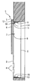
- FIG. 2 is a first AA arrow sectional view of the hall position indicator in the first embodiment.
- the hall position indicator 1 is attached to the box 5.
- Box 5 is embedded in the hall wall.
- the box 5 is formed in a structure with an open front surface.
- the button plate 2 is formed in a plate shape, for example.
- the button plate 2 is disposed so as to block a part of the opening of the box 5.
- the upper end of the button plate 2 is positioned below the upper end of the opening of the box 5.
- the face plate 3 has, for example, a structure having a front surface, an upper surface, a side surface, and a bottom surface, and an open rear side.
- the face plate 3 is disposed so as to block the remaining portion of the opening of the box 5 that is not blocked by the button plate 2.
- the upper end of the face plate 3 is located above the upper end of the opening of the box 5.
- a frame 6 is provided inside the face plate 3.
- the frame 6 is provided along the longitudinal direction of the face plate 3.
- the frame 6 can be fixed to the button plate 2 with bolts 7 and nuts 8.
- An upper holding device 9 is attached to the rear side of the face plate 3.
- the cross section of the upper holding device 9 has, for example, an L shape.
- a piece along the vertical direction of the upper holding device 9 is fixed to the frame 6 with bolts 10 and nuts 11.
- One piece of the upper holding device 9 is fixed, for example, with the plate-like member 12 sandwiched between the upper holding device 9 and the frame 6.
- the plate-like member 12 is formed to have the same thickness as the button plate 2, for example.
- the lower holding device 13 is attached to the rear side of the button plate 2.
- the structure of the lower holding device 13 is the same as that of the upper holding device 9, for example.
- the lower holding device 13 is provided, for example, in an upside down direction with respect to the upper holding device 9.
- the lower holding device 13 is fixed to the lower end portion of the button plate 2 with, for example, bolts and nuts (not shown).
- Box 5 is provided with pin 14 and pin 15.
- the pin 14 protrudes downward from the ceiling of the box 5.
- the pin 15 protrudes upward from the bottom surface of the box 5.
- the upper holding device 9 is detachably attached to the pin 14.
- the lower holding device 13 is detachably attached to the pin 15.
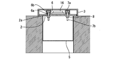
- FIG. 3 is a cross-sectional view taken along the line BB of the hall position indicator in the first embodiment.
- the indicator substrate 16 functions as a display unit that displays information on the front surface of the face plate 3.
- An opening 6 a is formed on the rear surface of the frame 6.
- the opening 6 a faces the front surface of the button plate 2.
- a groove 6b communicating with the opening 6a is formed inside the frame 6. The width of the groove 6b is larger than the width of the opening 6a.
- the button plate 2 has, for example, two holes 2a.
- the hole 2 a faces the opening 6 a of the frame 6.
- the hole 2a is formed at the upper end of the button plate 2, for example.
- the bolt head 7 a of the bolt 7 is located inside the groove 6 b of the frame 6.
- the width of the bolt head 7a is larger than the width of the opening 6a and smaller than the width of the groove 6b.
- the bolt 7 is arranged in such a direction that the bolt screw portion 7b is on the opening 6a side.
- the bolt screw portion 7 b protrudes from the opening 6 a of the frame 6 and is inserted into the hole portion 2 a of the button plate 2.
- the nut 8 is attached to the bolt screw portion 7 b from the rear side of the button plate 2.
- the face plate 3 When the nut 8 is tightened, the face plate 3 is fixed to the button plate 2. In a state where the nut 8 is not tightened, the face plate 3 can slide with respect to the button plate 2 by moving the bolt 7 along the groove 6 b of the frame 6.
- the bolt 7 and the nut 8 function as parts for adjusting the position of the face plate 3 with respect to the button plate 2.
- FIG. 4 is a cross-sectional view taken along the line CC of the hall position indicator in the first embodiment.
- two holes 12 a are formed in the plate-like member 12.
- the hole 12 a faces the opening 6 a of the frame 6.
- two holes are formed in one piece along the vertical direction of the upper holding device 9. These holes face the holes 12 a of the plate-like member 12.
- a notch larger than the diameter of the pin 14 is formed in the other piece along the horizontal direction of the upper holding device 9.
- the bolt head 10 a of the bolt 10 is located inside the groove 6 b of the frame 6.
- the width of the bolt head 10a is larger than the width of the opening 6a and smaller than the width of the groove 6b.
- the bolt 10 is arranged in such a direction that the bolt screw portion 10b is on the opening 6a side.
- the bolt screw portion 10 b protrudes from the opening 6 a of the frame 6 and is inserted into the hole portion 12 a of the plate-like member 12 and the hole portion formed in one piece of the upper holding device 9.
- the nut 11 is attached to the bolt screw portion 10b from the rear side of one piece of the upper holding device 9.
- the upper holding device 9 is provided with a spring 17 and a spacer 18.
- the spring 17 and the spacer 18 are sandwiched between a piece of the upper holding device 9 along the vertical direction and the plate-like member 12.
- the spring 17 is a leaf spring, for example.
- the spacer 18 is formed with the same thickness as the spring 17, for example.
- the upper holding device 9 When the nut 11 is tightened, the upper holding device 9 is fixed to the face plate 3. In a state where the nut 11 is not tightened, the upper holding device 9 and the spring 17 can slide with respect to the face plate 3 by the bolt 10 moving along the groove 6 b of the frame 6.
- the lower holding device 13 is provided with, for example, a spring similar to the spring 17 and a spacer similar to the spacer 18.
- the spring and the spacer are sandwiched between a piece along the vertical direction of the lower holding device 13 and the button plate 2.
- the landing position indicator 1 is attached so as to be fitted into the box 5 in a state where the face plate 3 is fixed to the button plate 2 and the upper holding device 9 and the lower holding device 13 are attached.
- the spring 17 moves while deforming.
- the upper holding device 9 is detachably attached to the pin 14.
- the lower holding device 13 is detachably attached to the pin 15.
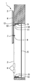
- FIG. 5 is a second AA arrow sectional view of the hall position indicator in the first embodiment.
- FIG. 6 is a third AA arrow sectional view of the hall position indicator in the first embodiment.
- FIG. 7 is a fourth AA arrow cross-sectional view of the hall position indicator in the first embodiment.
- FIG. 5 illustrates a case where the face plate 3 is slid upward from the state of FIG. In this case, the position of the upper holding device 9 with respect to the box 5 is held by changing the fixing position of the bolt 10 with respect to the face plate 3.
- FIG. 6 illustrates the case where the landing position indicator 1 is attached to a box 5 smaller than the box 5 shown in FIG.
- FIG. 7 illustrates a case where the landing position indicator 1 is attached to a box 5 larger than the box 5 shown in FIG.
- the position of the face plate 3 is adjusted so as to close the portion of the opening of the box 5 that is not closed by the button plate 2.
- the button plate 2 has the operation unit 4 and closes a part of the opening on the front surface of the box 5 embedded in the wall of the hall.
- the face plate 3 has a display unit, is provided so as to overlap a part of the front surface of the button plate 2, and is attached to the button plate 2 so as to be slidable along the longitudinal direction. For this reason, the openings of the boxes 5 having different sizes can be closed by the same face plate 3. As a result, when the hall position indicator 1 is refurbished, the common face plate 3 can be used for the existing boxes 5 having different sizes. In addition, since the position of the display unit can be arbitrarily adjusted, the design can be expanded and the visibility can be improved.
- the frame 6 is provided along the longitudinal direction of the face plate 3, and a groove 6 b facing the front surface of the button plate 2 is formed.
- the bolt 7 has a bolt head 7 a located inside the groove 6 b of the frame 6 and is inserted into a hole 2 a formed in the button plate 2.
- the nut 8 is attached to the bolt 7 from the rear side of the button plate 2.
- the face plate 3 can slide with respect to the button plate 2 in a state where the nut 8 is not tightened.
- the face plate 3 is fixed to the button plate 2 by tightening the nut 8. Therefore, the position of the face plate 3 with respect to the button plate 2 can be adjusted with a simple configuration.
- the present invention can be used for an elevator landing position indicator in which openings of boxes of different sizes are closed with the same face plate.
Landscapes
- Engineering & Computer Science (AREA)
- Automation & Control Theory (AREA)
- Computer Networks & Wireless Communication (AREA)
- Indicating And Signalling Devices For Elevators (AREA)
- Elevator Control (AREA)
Abstract
大きさが異なるボックスの開口を同一のフェースプレートで塞ぐことができるエレベーターの乗場位置表示器を提供する。この発明に係るエレベーターの乗場位置表示器(1)は、操作部(4)を有し、乗場の壁に埋め込まれたボックス(5)の前面の開口の一部分を塞ぐボタンプレート(2)と、表示部を有し、ボタンプレート(2)の前面の一部分と重なるように設けられ、ボタンプレート(2)に対してスライド可能に取り付けられるフェースプレート(3)と、を備える。
Description
この発明は、エレベーターの乗場位置表示器に関する。
エレベーターの乗場には、乗場位置表示器が設けられる。乗場位置表示器のフェースプレートは、乗場の壁に埋め込まれたボックスの開口を塞ぐように取り付けられる。特許文献1には、大きさが異なるボックスに同一の取付部材を用いて取り付けることができる乗場表示装置が開示されている。
特許文献1に記載の乗場表示装置では、取付部材を共通化できるが、フェースプレートを共通化できない。このため、大きさが異なるボックスの開口を同一のフェースプレートで塞ぐことができない。
この発明は、上記の課題を解決するためになされた。その目的は、大きさが異なるボックスの開口を同一のフェースプレートで塞ぐことができるエレベーターの乗場位置表示器を提供することである。
この発明に係るエレベーターの乗場位置表示器は、操作部を有し、乗場の壁に埋め込まれたボックスの前面の開口の一部分を塞ぐボタンプレートと、表示部を有し、ボタンプレートの前面の一部分と重なるように設けられ、ボタンプレートに対してスライド可能に取り付けられるフェースプレートと、を備える。
この発明によれば、フェースプレートは、ボタンプレートの前面の一部分と重なるように設けられ、ボタンプレートに対してスライド可能に取り付けられる。このため、大きさが異なるボックスの開口を同一のフェースプレートで塞ぐことができる。
以下、添付の図面を参照して実施の形態について説明する。各図において、同一または相当する部分には同一の符号が付される。重複する説明は、適宜簡略化あるいは省略する。
実施の形態1.
図1は、実施の形態1における乗場位置表示器の正面図である。
図1は、実施の形態1における乗場位置表示器の正面図である。
乗場位置表示器1は、例えば、エレベーターの乗場に設けられる操作盤である。乗場位置表示器1は、例えば、図1に示すように、乗場ドア付近の壁に設けられる。
乗場位置表示器1は、ボタンプレート2およびフェースプレート3を備える。ボタンプレート2およびフェースプレート3は、例えば、上下方向に長く形成される。
ボタンプレート2には、例えば、1つまたは複数の操作部4が設けられる。操作部4としては、例えば、乗場呼びボタンまたは行先階ボタン等が設けられ得る。
フェースプレート3は、ボタンプレート2の前面の一部分と重なるように設けられる。フェースプレート3の下端は、例えば、操作部4よりも上方に位置する。フェースプレート3の前面には、例えば、エレベーターの運行状況等の情報が表示される。運行状況には、例えば、かごが位置する階床およびかごの移動方向等が含まれる。
図2は、実施の形態1における乗場位置表示器の第1のA-A矢視断面図である。
図2に示すように、乗場位置表示器1は、ボックス5に取り付けられる。ボックス5は、乗場の壁に埋め込まれる。ボックス5は、前面が開口した構造に形成される。
ボタンプレート2は、例えば、板状に形成される。ボタンプレート2は、ボックス5の開口の一部分を塞ぐように配置される。ボタンプレート2の上端は、例えば、ボックス5の開口の上端よりも下方に位置する。
フェースプレート3は、例えば、前面、上面、側面および底面を有し、後方が開口した構造に形成される。フェースプレート3は、ボックス5の開口のうちボタンプレート2で塞がれない残りの部分を塞ぐように配置される。フェースプレート3の上端は、例えば、ボックス5の開口の上端よりも上方に位置する。
フェースプレート3の内側には、フレーム6が設けられる。フレーム6は、フェースプレート3の長手方向に沿って設けられる。フレーム6は、ボルト7およびナット8でボタンプレート2に対して固定可能である。
フェースプレート3の後側には、上部保持装置9が取り付けられる。上部保持装置9の断面は、例えば、L字状を呈する。上部保持装置9の上下方向に沿った一片は、ボルト10およびナット11でフレーム6に固定される。上部保持装置9の一片は、例えば、フレーム6との間に板状部材12を挟んだ状態で固定される。板状部材12は、例えば、ボタンプレート2と同じ厚さに形成される。
ボタンプレート2の後側には、下部保持装置13が取り付けられる。下部保持装置13の構造は、例えば、上部保持装置9と同様である。下部保持装置13は、例えば、上部保持装置9とは上下反転した向きで設けられる。下部保持装置13は、例えば、図示しないボルトおよびナットでボタンプレート2の下端部に固定される。
ボックス5には、ピン14およびピン15が設けられる。ピン14は、ボックス5の天井から下向きに突出する。ピン15は、ボックス5の底面から上向きに突出する。
上部保持装置9は、ピン14に対して着脱可能に取り付けられる。下部保持装置13は、ピン15に対して着脱可能に取り付けられる。
図3は、実施の形態1における乗場位置表示器のB-B矢視断面図である。
図3に示すように、フェースプレート3の内側には、例えば、2つのフレーム6が平行に設けられる。2つのフレーム6の間には、インジケータ基板16が設けられる。インジケータ基板16は、フェースプレート3の前面に情報を表示する表示部として機能する。
フレーム6の後面には、開口6aが形成される。開口6aは、ボタンプレート2の前面に対向する。フレーム6の内部には、開口6aから通じる溝6bが形成される。溝6bの幅は、開口6aの幅よりも大きい。
ボタンプレート2には、例えば、2つの穴部2aが形成される。穴部2aは、フレーム6の開口6aに対向する。穴部2aは、例えば、ボタンプレート2の上端部に形成される。
ボルト7のボルト頭部7aは、フレーム6の溝6bの内側に位置する。ボルト頭部7aの幅は、開口6aの幅よりも大きく、溝6bの幅よりも小さい。ボルト7は、ボルトネジ部7bが開口6a側となる向きで配置される。ボルトネジ部7bは、フレーム6の開口6aから突出し、ボタンプレート2の穴部2aに挿入される。ナット8は、ボタンプレート2の後側からボルトネジ部7bに取り付けられる。
ナット8が締め付けられると、フェースプレート3がボタンプレート2に対して固定される。ナット8が締め付けられていない状態では、ボルト7がフレーム6の溝6bに沿って移動することで、フェースプレート3がボタンプレート2に対してスライド可能である。ボルト7およびナット8は、ボタンプレート2に対するフェースプレート3の位置調整用の部品として機能する。
図4は、実施の形態1における乗場位置表示器のC-C矢視断面図である。
図4に示すように、板状部材12には、例えば、2つの穴部12aが形成される。穴部12aは、フレーム6の開口6aに対向する。
上部保持装置9の上下方向に沿った一片には、例えば、図示しない2つの穴部が形成される。これらの穴部は、板状部材12の穴部12aに対向する。
上部保持装置9の水平方向に沿った他片には、ピン14の径よりも大きい切欠きが形成される。
ボルト10のボルト頭部10aは、フレーム6の溝6bの内側に位置する。ボルト頭部10aの幅は、開口6aの幅よりも大きく、溝6bの幅よりも小さい。ボルト10は、ボルトネジ部10bが開口6a側となる向きで配置される。ボルトネジ部10bは、フレーム6の開口6aから突出し、板状部材12の穴部12aおよび上部保持装置9の一片に形成された穴部に挿入される。ナット11は、上部保持装置9の一片の後側からボルトネジ部10bに取り付けられる。
上部保持装置9には、バネ17およびスペーサ18が設けられる。バネ17およびスペーサ18は、上部保持装置9の上下方向に沿った一片と板状部材12との間に挟み込まれる。バネ17は、例えば、板バネである。スペーサ18は、例えば、バネ17と同じ厚さに形成される。
ナット11が締め付けられると、上部保持装置9がフェースプレート3に対して固定される。ナット11が締め付けられていない状態では、ボルト10がフレーム6の溝6bに沿って移動することで、上部保持装置9およびバネ17がフェースプレート3に対してスライド可能である。
なお、下部保持装置13には、例えば、バネ17と同様のバネおよびスペーサ18と同様のスペーサが設けられる。当該バネおよび当該スペーサは、下部保持装置13の上下方向に沿った一片とボタンプレート2との間に挟み込まれる。
乗場位置表示器1は、ボタンプレート2にフェースプレート3が固定され、上部保持装置9および下部保持装置13が取り付けられた状態で、ボックス5に嵌め込むようにして取り付けられる。ボックス5の奥に向かって乗場位置表示器1が押し込まれていくと、バネ17が変形しながら移動する。バネ17が図4に示すようにピン14に引っ掛かることで、上部保持装置9がピン14に対して着脱可能に取り付けられる。なお、下部保持装置13も、同様に、ピン15に対して着脱可能に取り付けられる。
図5は、実施の形態1における乗場位置表示器の第2のA-A矢視断面図である。図6は、実施の形態1における乗場位置表示器の第3のA-A矢視断面図である。図7は、実施の形態1における乗場位置表示器の第4のA-A矢視断面図である。
図5は、図4の状態よりも上方にフェースプレート3をスライドさせた場合を例示する。この場合、フェースプレート3に対するボルト10の固定位置を変更することで、ボックス5に対する上部保持装置9の位置が保持される。
図6は、図4に示すボックス5よりも小さいボックス5に乗場位置表示器1を取り付けた場合を例示する。図7は、図4に示すボックス5よりも大きいボックス5に乗場位置表示器1を取り付けた場合を例示する。これらの場合、フェースプレート3に対するボルト7の固定位置を変更することで、ボックス5の開口のうちボタンプレート2で塞がれない部分を塞ぐようにフェースプレート3の位置が調整される。
以上で説明した実施の形態1によれば、ボタンプレート2は、操作部4を有し、乗場の壁に埋め込まれたボックス5の前面の開口の一部分を塞ぐ。フェースプレート3は、表示部を有し、ボタンプレート2の前面の一部分と重なるように設けられ、ボタンプレート2に対して長手方向に沿ってスライド可能に取り付けられる。このため、大きさが異なるボックス5の開口を同一のフェースプレート3で塞ぐことができる。その結果、乗場位置表示器1を改修する際に、サイズが異なる既設のボックス5に対して共通のフェースプレート3を使用することができる。また、表示部の位置を任意に調整可能であるため、デザイン拡張および視認性向上を図ることができる。
また、フレーム6は、フェースプレート3の長手方向に沿って設けられ、ボタンプレート2の前面に対向する溝6bが形成されている。ボルト7は、フレーム6の溝6bの内側にボルト頭部7aが位置し、ボタンプレート2に形成された穴部2aに挿入される。ナット8は、ボタンプレート2の後側からボルト7に取り付けられる。フェースプレート3は、ナット8が締め付けられていない状態でボタンプレート2に対してスライド可能である。フェースプレート3は、ナット8が締め付けられることでボタンプレート2に対して固定される。このため、簡単な構成で、ボタンプレート2に対するフェースプレート3の位置を調整可能とすることができる。
この発明は、大きさが異なるボックスの開口を同一のフェースプレートで塞ぐエレベーターの乗場位置表示器に利用できる。
1 乗場位置表示器
2 ボタンプレート
2a 穴部
3 フェースプレート
4 操作部
5 ボックス
6 フレーム
6a 開口
6b 溝
7 ボルト
7a ボルト頭部
7b ボルトネジ部
8 ナット
9 上部保持装置
10 ボルト
10a ボルト頭部
10b ボルトネジ部
11 ナット
12 板状部材
12a 穴部
13 下部保持装置
14 ピン
15 ピン
16 インジケータ基板
17 バネ
18 スペーサ
2 ボタンプレート
2a 穴部
3 フェースプレート
4 操作部
5 ボックス
6 フレーム
6a 開口
6b 溝
7 ボルト
7a ボルト頭部
7b ボルトネジ部
8 ナット
9 上部保持装置
10 ボルト
10a ボルト頭部
10b ボルトネジ部
11 ナット
12 板状部材
12a 穴部
13 下部保持装置
14 ピン
15 ピン
16 インジケータ基板
17 バネ
18 スペーサ
Claims (3)
- 操作部を有し、乗場の壁に埋め込まれたボックスの前面の開口の一部分を塞ぐボタンプレートと、
表示部を有し、前記ボタンプレートの前面の一部分と重なるように設けられ、前記ボタンプレートに対してスライド可能に取り付けられるフェースプレートと、
を備えたエレベーターの乗場位置表示器。 - 前記フェースプレートの長手方向に沿って設けられ、前記ボタンプレートの前面に対向する溝が形成されたフレームと、
前記フレームの溝の内側に頭部が位置し、前記ボタンプレートに形成された穴部に挿入されるボルトと、
前記ボタンプレートの後側から前記ボルトに取り付けられるナットと、
を更に備え、
前記フェースプレートは、前記ナットが締め付けられていない状態で前記ボタンプレートに対してスライド可能である請求項1に記載のエレベーターの乗場位置表示器。 - 前記フェースプレートは、前記ナットが締め付けられることで前記ボタンプレートに対して固定される請求項2に記載のエレベーターの乗場位置表示器。
Priority Applications (3)
| Application Number | Priority Date | Filing Date | Title |
|---|---|---|---|
| CN201880094288.XA CN112218812B (zh) | 2018-06-12 | 2018-06-12 | 电梯的层站位置显示器 |
| JP2020524990A JP7056736B2 (ja) | 2018-06-12 | 2018-06-12 | エレベーターの乗場位置表示器 |
| PCT/JP2018/022462 WO2019239496A1 (ja) | 2018-06-12 | 2018-06-12 | エレベーターの乗場位置表示器 |
Applications Claiming Priority (1)
| Application Number | Priority Date | Filing Date | Title |
|---|---|---|---|
| PCT/JP2018/022462 WO2019239496A1 (ja) | 2018-06-12 | 2018-06-12 | エレベーターの乗場位置表示器 |
Publications (1)
| Publication Number | Publication Date |
|---|---|
| WO2019239496A1 true WO2019239496A1 (ja) | 2019-12-19 |
Family
ID=68843065
Family Applications (1)
| Application Number | Title | Priority Date | Filing Date |
|---|---|---|---|
| PCT/JP2018/022462 Ceased WO2019239496A1 (ja) | 2018-06-12 | 2018-06-12 | エレベーターの乗場位置表示器 |
Country Status (3)
| Country | Link |
|---|---|
| JP (1) | JP7056736B2 (ja) |
| CN (1) | CN112218812B (ja) |
| WO (1) | WO2019239496A1 (ja) |
Cited By (1)
| Publication number | Priority date | Publication date | Assignee | Title |
|---|---|---|---|---|
| WO2022176207A1 (ja) * | 2021-02-22 | 2022-08-25 | 三菱電機株式会社 | エレベーターの表示器具 |
Citations (6)
| Publication number | Priority date | Publication date | Assignee | Title |
|---|---|---|---|---|
| US5829554A (en) * | 1995-04-03 | 1998-11-03 | Innovation Industries Inc. | Hinged modular elevator control housing |
| JP2000044139A (ja) * | 1998-07-29 | 2000-02-15 | Hitachi Building Systems Co Ltd | エレベータのリニューアル方法 |
| JP2009249108A (ja) * | 2008-04-04 | 2009-10-29 | Mitsubishi Electric Building Techno Service Co Ltd | エレベーター押ボタン一体型位置表示器 |
| JP2010208724A (ja) * | 2009-03-09 | 2010-09-24 | Toshiba Elevator Co Ltd | エレベータ用保全装置 |
| JP2011246205A (ja) * | 2010-05-24 | 2011-12-08 | Hitachi Ltd | エレベータ用操作盤 |
| JP2013216480A (ja) * | 2012-04-12 | 2013-10-24 | Toshiba Elevator Co Ltd | エレベータ登録装置 |
Family Cites Families (8)
| Publication number | Priority date | Publication date | Assignee | Title |
|---|---|---|---|---|
| JP2003343026A (ja) * | 2002-05-24 | 2003-12-03 | Sankyo Alum Ind Co Ltd | パネル構造体 |
| JP2004323171A (ja) * | 2003-04-24 | 2004-11-18 | Mitsubishi Electric Corp | 群管理エレベータの呼び登録装置 |
| JP5598042B2 (ja) * | 2010-03-19 | 2014-10-01 | 三菱電機株式会社 | エレベータのかご操作盤 |
| JP6210919B2 (ja) * | 2014-03-27 | 2017-10-11 | 三菱電機株式会社 | エレベータ用操作盤、及びその取付方法 |
| CN204417036U (zh) * | 2014-12-25 | 2015-06-24 | 重庆威斯特电梯有限公司 | 杂物电梯收纳式升降台 |
| CN105110110B (zh) * | 2015-09-11 | 2017-05-03 | 苏州富士电梯有限公司 | 一种可旋转打开的电梯操纵箱 |
| CN205204540U (zh) * | 2015-12-23 | 2016-05-04 | 天津市南奥电梯技术有限公司 | 一种便于组装的电梯显示器 |
| CN205859805U (zh) * | 2016-07-22 | 2017-01-04 | 广州市博得电子科技有限公司 | 一种电梯用便于安装的照明灯 |
-
2018
- 2018-06-12 JP JP2020524990A patent/JP7056736B2/ja active Active
- 2018-06-12 WO PCT/JP2018/022462 patent/WO2019239496A1/ja not_active Ceased
- 2018-06-12 CN CN201880094288.XA patent/CN112218812B/zh active Active
Patent Citations (6)
| Publication number | Priority date | Publication date | Assignee | Title |
|---|---|---|---|---|
| US5829554A (en) * | 1995-04-03 | 1998-11-03 | Innovation Industries Inc. | Hinged modular elevator control housing |
| JP2000044139A (ja) * | 1998-07-29 | 2000-02-15 | Hitachi Building Systems Co Ltd | エレベータのリニューアル方法 |
| JP2009249108A (ja) * | 2008-04-04 | 2009-10-29 | Mitsubishi Electric Building Techno Service Co Ltd | エレベーター押ボタン一体型位置表示器 |
| JP2010208724A (ja) * | 2009-03-09 | 2010-09-24 | Toshiba Elevator Co Ltd | エレベータ用保全装置 |
| JP2011246205A (ja) * | 2010-05-24 | 2011-12-08 | Hitachi Ltd | エレベータ用操作盤 |
| JP2013216480A (ja) * | 2012-04-12 | 2013-10-24 | Toshiba Elevator Co Ltd | エレベータ登録装置 |
Cited By (1)
| Publication number | Priority date | Publication date | Assignee | Title |
|---|---|---|---|---|
| WO2022176207A1 (ja) * | 2021-02-22 | 2022-08-25 | 三菱電機株式会社 | エレベーターの表示器具 |
Also Published As
| Publication number | Publication date |
|---|---|
| JP7056736B2 (ja) | 2022-04-19 |
| CN112218812A (zh) | 2021-01-12 |
| CN112218812B (zh) | 2022-10-25 |
| JPWO2019239496A1 (ja) | 2021-02-12 |
Similar Documents
| Publication | Publication Date | Title |
|---|---|---|
| JP2013173613A (ja) | エレベータ用機器箱 | |
| JP6271079B2 (ja) | エレベータの操作盤 | |
| KR20170012354A (ko) | 엘리베이터의 문턱 | |
| JP4951867B2 (ja) | エレベータのかご操作盤 | |
| WO2019239496A1 (ja) | エレベーターの乗場位置表示器 | |
| JP5865954B2 (ja) | リニューアル用操作盤 | |
| JP2015221696A (ja) | エレベータの操作盤 | |
| JP5523151B2 (ja) | エレベータのホールランタン装置 | |
| WO2016013066A1 (ja) | エレベータの操作盤 | |
| JPWO2016139750A1 (ja) | エレベータの操作盤 | |
| US12286328B2 (en) | Operation display device for elevator | |
| JP6284780B2 (ja) | エレベーター | |
| JP6158112B2 (ja) | エレベーター | |
| US10442663B2 (en) | Cage lighting device for elevator and installation method therefor | |
| CN110775750A (zh) | 显示壁板以及电梯轿厢 | |
| JP6918127B2 (ja) | エレベータの発光装置 | |
| JP5020042B2 (ja) | エレベータの乗場釦装置 | |
| CN203173626U (zh) | 电梯的检查箱装置 | |
| JP6537727B2 (ja) | 乗場ドア遮煙装置とその取付方法、およびエレベーターの乗場装置とその据付方法 | |
| JP2015108232A (ja) | エントランスユニットの取付装置 | |
| JP2020196557A (ja) | エレベータ装置 | |
| JP2015020866A (ja) | エレベーターの乗場装置 | |
| JPWO2015181850A1 (ja) | エレベーター用かご | |
| JP6134150B2 (ja) | 引戸装置 | |
| JP2018095326A (ja) | エレベーター |
Legal Events
| Date | Code | Title | Description |
|---|---|---|---|
| 121 | Ep: the epo has been informed by wipo that ep was designated in this application |
Ref document number: 18922693 Country of ref document: EP Kind code of ref document: A1 |
|
| ENP | Entry into the national phase |
Ref document number: 2020524990 Country of ref document: JP Kind code of ref document: A |
|
| NENP | Non-entry into the national phase |
Ref country code: DE |
|
| 122 | Ep: pct application non-entry in european phase |
Ref document number: 18922693 Country of ref document: EP Kind code of ref document: A1 |