WO2019220857A1 - 管継手 - Google Patents
管継手 Download PDFInfo
- Publication number
- WO2019220857A1 WO2019220857A1 PCT/JP2019/016729 JP2019016729W WO2019220857A1 WO 2019220857 A1 WO2019220857 A1 WO 2019220857A1 JP 2019016729 W JP2019016729 W JP 2019016729W WO 2019220857 A1 WO2019220857 A1 WO 2019220857A1
- Authority
- WO
- WIPO (PCT)
- Prior art keywords
- joint
- tube connection
- connection hole
- hole
- wall
- Prior art date
Links
Images


Classifications
-
- F—MECHANICAL ENGINEERING; LIGHTING; HEATING; WEAPONS; BLASTING
- F16—ENGINEERING ELEMENTS AND UNITS; GENERAL MEASURES FOR PRODUCING AND MAINTAINING EFFECTIVE FUNCTIONING OF MACHINES OR INSTALLATIONS; THERMAL INSULATION IN GENERAL
- F16L—PIPES; JOINTS OR FITTINGS FOR PIPES; SUPPORTS FOR PIPES, CABLES OR PROTECTIVE TUBING; MEANS FOR THERMAL INSULATION IN GENERAL
- F16L37/00—Couplings of the quick-acting type
- F16L37/08—Couplings of the quick-acting type in which the connection between abutting or axially overlapping ends is maintained by locking members
- F16L37/12—Couplings of the quick-acting type in which the connection between abutting or axially overlapping ends is maintained by locking members using hooks, pawls or other movable or insertable locking members
-
- F—MECHANICAL ENGINEERING; LIGHTING; HEATING; WEAPONS; BLASTING
- F16—ENGINEERING ELEMENTS AND UNITS; GENERAL MEASURES FOR PRODUCING AND MAINTAINING EFFECTIVE FUNCTIONING OF MACHINES OR INSTALLATIONS; THERMAL INSULATION IN GENERAL
- F16L—PIPES; JOINTS OR FITTINGS FOR PIPES; SUPPORTS FOR PIPES, CABLES OR PROTECTIVE TUBING; MEANS FOR THERMAL INSULATION IN GENERAL
- F16L37/00—Couplings of the quick-acting type
- F16L37/08—Couplings of the quick-acting type in which the connection between abutting or axially overlapping ends is maintained by locking members
- F16L37/084—Couplings of the quick-acting type in which the connection between abutting or axially overlapping ends is maintained by locking members combined with automatic locking
- F16L37/091—Couplings of the quick-acting type in which the connection between abutting or axially overlapping ends is maintained by locking members combined with automatic locking by means of a ring provided with teeth or fingers
- F16L37/0915—Couplings of the quick-acting type in which the connection between abutting or axially overlapping ends is maintained by locking members combined with automatic locking by means of a ring provided with teeth or fingers with a separate member for releasing the coupling
-
- F—MECHANICAL ENGINEERING; LIGHTING; HEATING; WEAPONS; BLASTING
- F16—ENGINEERING ELEMENTS AND UNITS; GENERAL MEASURES FOR PRODUCING AND MAINTAINING EFFECTIVE FUNCTIONING OF MACHINES OR INSTALLATIONS; THERMAL INSULATION IN GENERAL
- F16L—PIPES; JOINTS OR FITTINGS FOR PIPES; SUPPORTS FOR PIPES, CABLES OR PROTECTIVE TUBING; MEANS FOR THERMAL INSULATION IN GENERAL
- F16L37/00—Couplings of the quick-acting type
- F16L37/08—Couplings of the quick-acting type in which the connection between abutting or axially overlapping ends is maintained by locking members
- F16L37/12—Couplings of the quick-acting type in which the connection between abutting or axially overlapping ends is maintained by locking members using hooks, pawls or other movable or insertable locking members
- F16L37/1225—Couplings of the quick-acting type in which the connection between abutting or axially overlapping ends is maintained by locking members using hooks, pawls or other movable or insertable locking members using a retaining member the extremities of which, e.g. in the form of a U, engage behind a shoulder of both parts
-
- F—MECHANICAL ENGINEERING; LIGHTING; HEATING; WEAPONS; BLASTING
- F16—ENGINEERING ELEMENTS AND UNITS; GENERAL MEASURES FOR PRODUCING AND MAINTAINING EFFECTIVE FUNCTIONING OF MACHINES OR INSTALLATIONS; THERMAL INSULATION IN GENERAL
- F16L—PIPES; JOINTS OR FITTINGS FOR PIPES; SUPPORTS FOR PIPES, CABLES OR PROTECTIVE TUBING; MEANS FOR THERMAL INSULATION IN GENERAL
- F16L2201/00—Special arrangements for pipe couplings
- F16L2201/10—Indicators for correct coupling
Definitions
- the present invention relates to a pipe joint, and more particularly to a pipe joint for fluid pressure equipment.
- Pipe fittings used by attaching to fluid pressure devices such as solenoid valves and fluid pressure cylinders are well known as disclosed in, for example, Patent Document 1 and Patent Document 2.
- a circular tube connection hole for connecting a tube for piping is generally formed in a synthetic resin joint body to be attached to the fluid pressure device, and the tube connection hole is formed inside the tube connection hole.
- a metal locking ring that locks the tube by locking it to the outer periphery of the tube inserted into the tube connection hole, and a release member for releasing the locking of the locking ring to the tube
- a cylindrical metal joint guide that guides the release member, and a packing that seals between the inner periphery of the tube connection hole and the outer periphery of the tube.
- the joint guide is attached to the inside of the tube connection hole by press-fitting.
- the outer periphery of the joint guide is an annular inverted hook (return) that is locked to the inner circumference of the tube connection hole and performs a retaining function.
- the outer diameter of the reverse rod is slightly larger than the inner diameter of the tube connection hole, so that the press-fitting resistance when the fitting guide is press-fitted into the tube connection hole is very large. Therefore, the attachment of the joint guide is difficult.
- the joint body is formed of a hard and brittle synthetic resin such as a synthetic resin containing glass fiber, the joint body is unlikely to be deformed so that the tube connection hole expands, so that cracking occurs. In some cases, the joint guide cannot be attached.
- the technical problem of the present invention is that inside a tube connection hole formed in a joint body made of synthetic resin, a locking ring that locks to the tube, a release member that releases locking of the locking ring, In a pipe joint that houses a metal joint guide that guides a release member, the fitting guide is press-fitted into the tube connection hole by simpler and more reliable attachment than before. .
- a locking ring that locks the outer periphery of a tube inserted into the tube connection hole inside the tube connection hole formed in the joint body, and the locking
- a cylindrical release member that releases the locking of the ring
- a metal-made joint guide that guides the release member, and a packing that seals between the inner periphery of the tube connection hole and the outer periphery of the tube
- the joint guide has a reverse hook for retaining at the outer periphery, and is press-fitted into the tube connection hole, and the joint guide is disposed at the inner periphery of the tube connection hole.
- a plurality of abutting walls having an inner wall surface that abuts the outer periphery of the tube connecting hole are formed to extend along the central axis at equiangular intervals around the central axis of the tube connection hole. The reverse hook is locked. Pipe fitting and is provided.
- the tube connection hole includes a non-circular first hole portion in which the abutting wall is formed, and a circular second hole portion connected to the first hole portion,
- the length in the central axis direction of the first hole portion is smaller than the length in the central axis direction of the joint guide, but is longer than the length from the base end of the joint guide to the reverse rod, and the joint guide has a tip at the first end.
- the tube is fitted into the inside of the second hole portion and is fitted into the tube connection hole in a state of fitting the reverse rod into the inside of the first hole portion. Is being housed.
- the diameter of the virtual cylindrical surface inscribed in all the contact walls is the same as the diameter of the second hole portion, and the inner wall surface of the contact wall is in contact with the virtual cylindrical surface. Even if it is a plane, it may be a concave curved surface forming a part of the virtual cylindrical surface.
- a recess is formed between the adjacent abutment walls, and the recesses prevent the reverse rod from being locked to a portion other than the abutment wall. It is an escape portion for allowing deformation of the joint guide at a portion other than the inner wall surface when a force by the contact wall acts on the joint guide at the same time, and The four abutting walls are formed at intervals of 90 degrees.
- the joint body has a cylindrical portion having a diameter larger than the lateral width of the joint body, and the tube connection hole is formed inside the cylindrical portion, On both side surfaces in the diameter direction of the cylindrical portion, planar cutout portions are formed to match the position of the side surface with the position of the side surface of the joint body, and the positions where the cutout portions are formed are adjacent to each other. It is a position between two contact walls.
- an electromagnetic valve to which the pipe joint having a cutout portion on the side surface of the cylindrical portion is attached.
- This solenoid valve has a main valve portion having a valve mechanism for switching a flow path, and an electromagnetic operation portion for driving the valve mechanism, and the main valve portion is a rectangular parallelepiped valve body incorporating the valve mechanism.
- the width of the valve body is the same as the width of the joint body, and the joint body is attached to the port forming surface of the valve body.
- the press-fitting resistance at that time is such that the entire outer peripheral surface of the joint guide is the inner peripheral surface of the tube connection hole. It is much smaller than the case where it is press-fitted while in contact with the whole. For this reason, the fitting guide can be press-fitted smoothly and easily. Further, when the joint guide is press-fitted, the force acting on the hole wall of the tube connection hole by the joint guide is absorbed mainly by compressing the contact wall, and the joint guide is also absorbed by the contact wall.
- the joint guide Since the joint guide is absorbed by a slight outward deformation of the joint guide at a position between the adjacent contact walls, the joint body is deformed by these synergistic effects. For this reason, even if the joint body is made of a hard synthetic resin containing glass fibers and weak against elongation, cracks due to deformation of the joint body are unlikely to occur.
- FIG. 6 is a cross-sectional view of the pipe joint of FIG. 5 cut along the line IV-IV, and shows a state in which the joint component and the packing are taken out from one tube connection hole. It is the figure which looked at the pipe joint of FIG. 4 from the front.
- FIG. 6 is a partial cross-sectional view of the pipe joint of FIG. 5 cut along line VI-VI. It is a disassembled perspective view of the coupling components and packing accommodated in a tube connection hole.
- FIG. 6 is an enlarged front view of the lower tube connection hole in FIG. 5.
- FIG. 11 is an exploded view of FIG. 10. It is an enlarged front view of the tube connection hole in FIG.
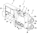
- the electromagnetic valve 1 includes a main valve portion 3 having a valve mechanism for switching a fluid flow path, and an electromagnetic operation portion 4 for driving the valve mechanism.
- the other solenoid valves 1A having the same structure are used in an assembled state by sequentially connecting them in a state where they are in direct contact with each other in the lateral width direction. Since the structure of such a solenoid valve 1 is publicly known (see, for example, Japanese Patent Application Laid-Open No. 2005-308122), the main structure and operation will be briefly described here. In the present embodiment, the fluid used is air.
- the main valve portion 3 of the electromagnetic valve 1 has a rectangular parallelepiped valve body 6 incorporating the valve mechanism.
- the valve body 6 is formed by combining a first block 6a containing the valve mechanism, a second block 6b serving as a manifold, and a third block 6c also serving as a piston box,
- the front view shape of the valve body 6, that is, the shape viewed from the first end 7 a side, is a rectangular shape elongated in the vertical direction, and the left and right side surfaces 6 d and 6 d of the valve body 6 are substantially flat.
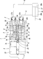
- a valve hole 10 extending from the first end 7a side toward the opposite second end 7b side is formed in the first block 6a, and a spool 11 is slidably accommodated in the valve hole 10.
- a large-diameter first piston 12 and a small-diameter second piston 13 that receive pilot air and move the spool 11 are disposed at one end and the other end of the spool 11.
- the valve hole 10 communicates with one supply hole 14, a first discharge hole 15a and a second discharge hole 15b, and a first output hole 16a and a second output hole 16b.
- the first discharge hole 15a and the second discharge hole 15b communicate with the discharge port 18 formed in the second block 6b, and communicate with the supply port 17 formed in the second block 6b.
- the output hole 16a and the second output hole 16b individually communicate with the first output port 19a and the second output port 19b that open to the first block 6a, that is, the first end 7a of the valve body 6. Therefore, the first end 7a is a port forming surface of the valve body 6, and the quick connection type pipe joint 2 is attached to the port forming surface 7a.
- the electromagnetic operating unit 4 includes a pilot body 22 connected to the second end 7 b side of the valve body 6, a three-port pilot electromagnetic valve 23 attached to the pilot body 22, and the pilot body 22. And a pilot supply port 24 formed at the bottom.
- the pilot supply port 24 communicates with the first piston chamber 12a behind the first piston 12 via the pilot solenoid valve 23, and is connected to the second piston 13 behind the second piston 13 through a pilot flow path (not shown). It always communicates with the piston chamber 13a.
- the first piston chamber 12a When the pilot solenoid valve 23 is not energized, the first piston chamber 12a is opened to the atmosphere via the pilot solenoid valve 23, so that the spool 11 is pushed by the second piston 13. Occupying the illustrated first switching position, the supply hole 14 communicates with the second output hole 16b, and the first output hole 16a communicates with the first discharge hole 15a.
- the air output from the output port 19b to the rod side pressure chamber 26b of the air cylinder 25 through the synthetic resin tube 8 connected to the pipe joint 2 and discharged from the head side pressure chamber 26a of the air cylinder 25 is Then, it flows into the first output port 19a from the other tube 8 through the pipe joint 2, and is discharged from the discharge port 18 through the first output hole 16a and the first discharge hole 15a. It is. For this reason, the piston 27 and the rod 28 of the air cylinder 25 occupy the retracted positions.
- pilot air is supplied to the first piston chamber 12a through the pilot solenoid valve 23, so that the spool 11 is pushed by the large-diameter first piston 12 and has the illustrated position. Occupies the opposite second switching position, the supply hole 14 communicates with the first output hole 16a, the second output hole 16b communicates with the second discharge hole 15b, and air from the supply port 17
- the air that is output to the head side pressure chamber 26a of the air cylinder 25 through the one output port 19a and discharged from the rod side pressure chamber 26b of the air cylinder 25 passes through the second output port 16b and the second output hole 16b. It is discharged from the discharge port 18 through the discharge hole 15b. For this reason, the piston 27 and the rod 28 of the air cylinder 25 move forward.
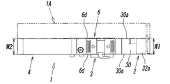
- the pipe joint 2 has a joint body 30 made of synthetic resin.
- the shape of the joint body 30 as viewed from the front side that is, the shape seen from the front side where the tube connection holes 31a and 31b are opened, is a vertically elongated rectangular shape like the valve body 6 of the solenoid valve 1. Yes. Further, the left and right side surfaces 30a, 30a of the joint body 30 are flat, and the lateral width W1 (see FIG. 2) of the joint body 30 is substantially the same as the lateral width W2 of the valve body 6.
- a synthetic resin forming the joint body 30 for example, PBT (polybutylene terephthalate) is suitable.
- the upper and lower cylinder parts 32a and 32b are formed on the front surface of the joint body 30, and the tube connection holes 31a and 31b are formed inside the cylinder parts 32a and 32b.
- the first tube connection hole 31a formed in the upper first cylinder part 32a communicates with the first output port 19a of the valve body 6 through the flow path hole 33a, and the first tube connection hole 31a formed in the lower second cylinder part 32b.
- the two-tube connection hole 31b communicates with the second output port 19b of the valve body 6 through the flow path hole 33b.
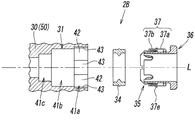
- a plurality of joint components and packings 34 are accommodated in the tube connection holes 31a and 31b, respectively.
- the joint component includes a locking ring 35 that locks to the outer periphery of the tube 8 inserted into the tube connection holes 31a and 31b, and a pushable release member that releases the locking of the locking ring 35.
- 36 and a joint guide 37 for guiding the release member 36, and the packing 34 seals between the inner periphery of the tube connection hole 31 and the outer periphery of the tube 8.
- the first tube connection hole 31a and the second tube connection hole 31b have the same structure, including the joint component and the packing 34 housed in each of the first tube connection hole 31a and the second tube connection hole 31b. Since the first tube portion 32a and the second tube portion 32b also have substantially the same configuration, in the following description, the first tube connection hole 31a, the second tube connection hole 31b, and the first tube portion When it is not necessary to distinguish between the 32a and the second cylindrical portion 32b, they are simply referred to as the “tube connection hole 31” and the “cylindrical portion 32”. The same applies to the flow path holes 33a and 33b.
- the cylindrical portions 32 collide with each other when connecting the plurality of solenoid valves 1 and 1A as shown in FIG. In order to prevent this, on both side surfaces of the cylindrical portion 32 in the diametrical direction, that is, both side surfaces facing the lateral width W1 direction of the joint body 30, as shown in FIGS. In order to match the position of the side surface of the joint body 30, a planar cutout 38 is formed.
- the locking ring 35 is formed into a cylindrical shape by pressing a thin metal plate made of stainless steel, and has a trunk portion 35a on the base end side.
- a locking portion 35b on the distal end side, and the locking portion 35b is inclined in a direction in which the diameter gradually decreases toward the distal end side, and the outer periphery of the tube 8 is disposed at the distal end of the locking portion 35b.
- the edge 35c which latches to is formed.
- the locking ring 35 has a plurality of first slits 35d extending in the direction of the central axis L of the tube connection hole 31 extending from the distal end of the locking portion 35b to a position near the proximal end of the trunk portion 35a.
- the second slit 35e is positioned between the adjacent first slit 35d and the first slit 35d from the base end of the trunk portion 35a to the locking portion 35b. It is formed at equal intervals so as to extend to near.
- the release member 36 is a cylindrical member made of synthetic resin, and has a distal end that is close to the inner surface of the locking portion 35b of the locking ring 35 and a proximal end that protrudes from the tube connection hole 31 to the outside.
- a flange portion 36a that protrudes outward in the radial direction is formed at the base end.
- the outer diameter of the flange portion 36 a is larger than the inner diameter of the tube connection hole 31, but smaller than the outer diameter of the cylindrical portion 32.
- a plurality of slits 36b are formed at equal intervals in the portion near the tip of the release member 36, and an annular protrusion 36c having a conical inclined surface 36d on the front surface is formed on the outer periphery of the release member 36.
- the release member 36 occupies a position where the inclined surface 36 d of the annular protrusion 36 c is locked to the proximal end of the locking ring 35 when not pushed into the tube connection hole 31.
- the flange portion 36a is pushed into the tube connection hole 31 by pushing with a finger, the annular projection 36c slides along the inner peripheral surface of the locking ring 35, and the tip of the release member 36 is engaged with the engagement member 35.
- the stopper 35b is pushed open to be separated from the tube 8. Therefore, in this state, the tube 8 can be extracted from the pipe joint 2.
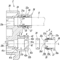
- the joint guide 37 regulates the locking ring 35 from being displaced in the central axis L direction and guides the release member 36 to be displaced in the central axis L direction.
- the joint guide 37 is formed into a cylindrical shape by pressing a metal plate such as stainless steel, and is press-fitted into the tube connection hole 31 and fixed. More specifically, the joint guide 37 has a guide body portion 37a on the base end side having a single cylinder structure (single structure) and a guide distal end portion 37b having a double cylinder structure (double structure). .
- the guide distal end portion 37b has an inner cylindrical portion 37c that is continuous with the guide main body portion 37a, and an outer cylindrical portion 37d that is formed by folding the distal end of the inner cylindrical portion 37c toward the outside of the inner cylindrical portion 37c.
- a reverse rod 37e (return) that rises obliquely toward the base end side of the joint guide 37 is formed in an annular shape at the folded end of the outer cylindrical portion 37d.
- the inner wall 42 a of the abutting wall 42 formed in the connection hole 31 bites into and is locked.
- the reverse rod 37e is divided into a plurality of arc-shaped small portions by a plurality of cuts 37f provided at equal intervals, whereby when the joint guide 37 is press-fitted into the tube connection hole 31
- the reverse rod 37e is easily elastically deformed in the direction in which the diameter of the reverse rod 37e is reduced. Therefore, the joint guide 37 can be easily press-fitted.
- the inner diameter of the inner cylinder part 37c at the guide tip part 37b is smaller than the inner diameter of the guide body part 37a, and the outer diameter of the outer cylinder part 37d is substantially equal to the outer diameter of the guide body part 37a.
- An annular guide portion 37g is formed at the base end portion of the guide main body portion 37a so that the end portion is inwardly rounded in a substantially circular shape, and the annular guide portion 37g contacts the outer periphery of the release member 36. Thus, when the release member 36 is pushed in, the release member 36 is guided by the annular guide portion 37g.
- the tube connection hole 31 is a non-circular first hole into which the joint guide 37 is press-fitted in order from the inlet side toward the flow path hole 33 side.
- the length (depth) X of the first hole portion 41a in the central axis L direction is smaller than the length (depth) Y of the second hole portion 41b in the central axis L direction.
- the length Z it is larger than the length Zo from the base end of the joint guide 37 to the reverse rod 37e.
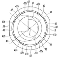
- a plurality of the abutting walls 42 projecting toward the center of the tube connection hole 31 are arranged at equiangular intervals around the central axis L of the tube connection hole 31 on the inner periphery of the first hole portion 41a.
- the inner wall surface 42 a of the corresponding contact wall 42 is in contact with the outer peripheral surface of the joint guide 37.
- four contact walls 42 are formed at intervals of 90 degrees.
- the said notch part 38 formed in the side surface of the said cylinder part 32 is arrange
- the inner wall surface 42 a of the abutting wall 42 forms a concave curved surface that curves outward in the radial direction of the tube connection hole 31, and the concave curved surface is a virtual cylindrical surface S that is coaxial with the tube connection hole 31.
- the diameter of the virtual cylindrical surface S is the same as the diameter of the second hole portion 41b. Therefore, the radius of curvature of the concave curved surface is the same as the radius of curvature of the second hole portion 41b. It is. For this reason, the inner wall surface 42a of the contact wall 42 and the inner peripheral surface of the second hole portion 41b are smoothly connected without any step.
- the diameter of the virtual cylindrical surface S is the same as or slightly larger than the outer diameter of the guide main body 37a in the joint guide 37, but smaller than the diameter of the reverse rod 37e.
- the cross-sectional shape of the abutting wall 42 in the direction orthogonal to the central axis L is such that the wall width gradually increases from the inner wall surface 42a side to the proximal end side of the corresponding wall wall 42.
- the left and right side wall surfaces 42b of the contact wall 42 are each curved into a concave curved surface.
- a concave portion 43 that is curved in a partial cylindrical surface is interposed between the adjacent abutting walls 42 and 42, and a side wall surface 42 b of the abutting wall 42 is formed by a part of the concave portion 43. Is formed.
- the radius of curvature of the recess 43 is smaller than the radius of curvature of the tube connection hole 31, that is, the second hole portion 41b.
- the depth of the concave portion 43 is deepest at an intermediate position between the adjacent contact walls 42 and 42, and the depth of the deepest portion is such that the reverse rod 37 e of the joint guide 37 is not in contact. It is. In other words, the diameter of the circle in contact with the deepest part of all the recesses 43 is larger than the outer diameter of the reverse rod 37e. Accordingly, the concave portion 43 serves as a relief portion for preventing the reverse rod 37e from being locked to a portion other than the contact wall 42.
- the abutting wall 42 has an end wall surface 42c facing the inlet of the tube connection hole 31, and the end wall surface 42c gradually becomes deeper in the tube connection hole 31 toward the inner wall surface 42a side. The direction is inclined toward the second hole portion 41b.
- the contact wall 42 can be formed as follows, for example. That is, from the state where the first hole portion 41a is formed as a circular hole overlapping the virtual cylindrical surface S, the inner periphery of the hole is cut with the drill D to form the four concave portions 43 at intervals of 90 degrees. Thus, the abutting wall 42 can be formed between the adjacent recesses 43.
- the tube connection hole 31 is formed in this way, when the joint guide 37 is press-fitted into the tube connection hole 31, the joint guide 37 is moved by the inclined end wall surface 42c of the contact wall 42.
- the tube connection hole 31 is guided to a position coaxial with the tube connection hole 31 and then pushed into the first hole portion 41 a of the tube connection hole 31.
- the outer peripheral surface of the joint guide 37 strongly contacts the inner wall surface 42a of the contact wall 42 mainly at the portion of the reverse rod 37e, the reverse rod 37e is elastically deformed in a direction in which the diameter decreases.
- the abutting wall 42 is compressed in the direction in which the diameter of the virtual cylindrical surface S is enlarged by the reverse rod 37e.
- the joint guide 37 is press-fitted to a position where the proximal end of the annular guide portion 37g and the inlet end of the tube connection hole 31 coincide with each other while being guided by the inner wall surface 42a.
- the reverse rod 37e is fixed by being locked to the inner wall surface 42a of each contact wall 42.
- a part of the guide front end portion 37b enters the second hole portion 41b.
- the joint guide 37 is press-fitted in a state where the outer peripheral surface is in partial contact with the inner peripheral surface of the tube connection hole 31 by contacting the plurality of abutting walls 42.
- the resistance is much smaller than when the entire outer peripheral surface of the joint guide 37 is press-fitted in a state where it is in contact with the entire inner peripheral surface of the tube connection hole 31.
- the joint guide 37 can be press-fitted smoothly and easily.
- the inner wall surface 42a of the abutting wall 42 has a concave curved surface shape and comes into contact with the outer peripheral surface of the joint guide 37 in a state in which the inner wall surface 42a is exactly fitted, It is always stable both in time and after press-fitting.
- the cylindrical portion 32 of the joint body 30 made of synthetic resin receives a force in a direction in which the diameter increases, and this force mainly compresses the contact wall 42.
- the compressive force that is absorbed by the contact wall 42 and acts inward (in the direction of the central axis L) on the joint guide 37 by the contact wall 42 causes the joint guide 37 to be slightly outwardly elastic at the position of the recess 43. Since it is relieved by deformation, the force acting on the joint body 30 is reduced by these synergistic actions. For this reason, the entire cylindrical portion 32 is hardly deformed.
- the cylindrical portion 32 is prevented from being deformed at the notch portion 38 and cracking of the cylindrical portion 32 is prevented. be able to.
- the said notch part 38 does not need to be provided when the outer diameter of the said cylinder part 32 is equal to or less than the horizontal width of a joint main body.
- the four contact walls 42 are provided inside the tube connection hole 31. Even if the number of the contact walls 42 is two, the number of contact walls 42 is three. Or five or more.
- the joint body 30 includes two tube connection holes 31.
- the present invention is similar to the pipe joint 2A of the second embodiment shown in FIG.
- the present invention can also be applied to a pipe joint in which the body 50 has one tube connection hole 31.
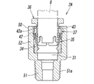
- the pipe joint 2A according to the second embodiment is of a type that is used by being directly attached to a port of a fluid pressure device, and the fitting body 50 has a male screw 51a on the outer periphery for screwing into the screw hole of the port.
- the tube connection hole 31 is formed in the same manner as the tube connection hole 31 of the first embodiment, and inside the tube connection hole 31, A joint component and packing 34 similar to those in the case of the pipe joint 2 of the first embodiment are accommodated.
- the same reference numerals as those of the pipe joint 2 of the first embodiment are attached to portions corresponding to the pipe joint 2 of the first embodiment, and the description of the configuration thereof Omitted.
- the inner wall surface 42a of the abutment wall 42 has a concave curved surface shape, but the inner wall surface 42a is formed of the virtual cylindrical surface S. It may be a plane in contact with.
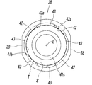
- 10 to 12 show another example of the pipe joint in which the inner wall surface 42a of the contact wall 42 forms a flat surface as a third embodiment.
- the configuration of the tube connection hole 31, particularly, the configuration of the first hole portion 41a is different from the pipe joints 2 and 2A of the first or second embodiment, Other configurations are substantially the same as the pipe joints 2 and 2A of the first or second embodiment.
- the configuration of the first hole portion 41a will be described, and for the other configurations, the same components as those in the first or second embodiment will be denoted by the same reference numerals, Shall be omitted.
- the tube connection hole 31 includes a non-circular first hole portion 41a, a circular second hole portion 41b, and a circular third hole portion 41c, and the first hole portion.
- the four abutting walls 42 are formed at intervals of 90 degrees around the central axis L, and a concave portion 43 that is curved in an arc shape is formed between the adjacent abutting walls 42 and 42. Has been.
- the inner wall surface 42a of the abutting wall 42 is a flat surface in contact with the virtual cylindrical surface S having the same diameter as the second hole portion 41b, and one end of the concave portion 43 located on one side of the corresponding wall 42 and the corresponding contact. One end of the recess 43 located on the other side of the wall 42 is linearly connected.
- the inner wall surface 42 a is a single plane that extends over the entire lateral width of the contact wall 42.
- the concave portion 43 has a partial cylindrical surface shape and is located on the same axis as the virtual cylindrical surface S and forms a part of another virtual cylindrical surface T having a larger diameter than the virtual cylindrical surface S. is there.
- the fitting guide 37 is press-fitted into the tube connection hole 31 in the same manner as the pipe joints 2 and 2A of the first and second embodiments.
- the inner wall surface 42a of the abutting wall 42 is in contact with the joint guide 37 at a position in contact with the virtual cylindrical surface S, that is, a center position in the width direction of the inner wall surface 42a.
- the inner wall surface 42 a of the abutting wall 42 does not necessarily extend over the entire width of the corresponding wall 42, and if the inner wall surface 42 a is partially formed in a portion in contact with the joint guide 37.
- the portion connecting the side end portion of the partially formed inner wall surface 42a and the side end portion of the recess 43 (the portion corresponding to the side wall surface 42b in FIG. 8) is relative to the inner wall surface 42a. It may be inclined linearly.
- the end wall surface of the abutting wall 42 is gradually inclined toward the inner wall surface 42a side toward the inner side of the tube connection hole 31 in the same manner as the end wall surface 42c of the abutting wall 42 in the pipe joint 2 of the first embodiment. It can also be an inclined surface.
- the present invention can be applied to a pipe joint for connecting tubes, that is, a pipe joint having tube connection holes at both ends of a joint body.
Abstract
Description
また、前記継手ガイドの圧入時に、該継手ガイドによって前記チューブ接続孔の孔壁に作用する力は、主として前記当接壁が圧縮されることによって吸収され、また、前記当接壁によって前記継手ガイドに作用する力は、隣接する当接壁と当接壁との間の位置で該継手ガイドが僅かに外側に変形することよって吸収されるため、これらの相乗作用によって前記継手ボディの変形は生じにくく、このため、該継手ボディがガラス繊維入りの硬くて伸びに弱い合成樹脂で形成されている場合であっても、前記継手ボディの変形による割れが生じにくい。
前記第1孔部分41aの中心軸L方向の長さ(深さ)Xは、前記第2孔部分41bの中心軸L方向の長さ(深さ)Yより小さく、また、前記継手ガイド37の長さZよりも若干小さいが、該継手ガイド37の基端から前記逆鉤37eまでの長さZoよりは大きい。
また、前記仮想円柱面Sの直径は、前記継手ガイド37におけるガイド本体部37aの外径と同じか又はそれより僅かに大きいが、前記逆鉤37eの直径よりは小さい。
また、隣り合う前記当接壁42と当接壁42との間には、部分円筒面状に湾曲する凹部43が介設され、該凹部43の一部によって前記当接壁42の側壁面42bが形成されている。前記凹部43の曲率半径は、前記チューブ接続孔31即ち第2孔部分41bの曲率半径より小さい。前記凹部43の深さは、前記隣り合う当接壁42と当接壁42との中間の位置で最も深く、該最も深い部分の深さは、前記継手ガイド37の逆鉤37eが接触しない程度である。換言すれば、全ての凹部43の最深部に接する円の直径は、前記逆鉤37eの外径より大きい。従って、前記凹部43は、前記逆鉤37eが前記当接壁42以外の部分に係止しないようにするための逃げ部となるものである。
また、前記当接壁42の内壁面42aは凹曲面状をしていて、前記継手ガイド37の外周面にぴったり馴染んだ状態で接触するため、該当接壁42による継手ガイド37の支持は、圧入時においても圧入後においても常に安定的である。
なお、前記切欠部38は、前記筒部32の外径が継手本体の横幅と同等以下である場合には設ける必要がない。
この第2実施形態の管継手2Aは、流体圧機器のポートに直接取り付けて使用するタイプのもので、継手ボディ50が、前記ポートの螺子孔にねじ込むための雄螺子51aを外周に有する取付部51と、チューブ接続孔31を有する筒部52とを有し、前記チューブ接続孔31が前記第1実施形態のチューブ接続孔31と同様に形成されると共に、該チューブ接続孔31の内部に、前記第1実施形態の管継手2の場合と同様の継手用部品及びパッキン34が収容されている。このため、この第2実施形態の管継手2Aにおいては、前記第1実施形態の管継手2に対応する部分に該第1実施形態の管継手2と同じ符号を付し、その構成の説明は省略する。
前記凹部43は、部分円柱面状をしていて、前記仮想円柱面Sと同軸上に位置して該仮想円柱面Sより大径をなす別の仮想円柱面Tの一部を形成するものである。
また、前記当接壁42の端壁面は、第1実施形態の管継手2における当接壁42の端壁面42cと同様に、内壁面42a側に向かって次第にチューブ接続孔31の奥方向に傾斜する傾斜面とすることもできる。
2,2A,2B 管継手
3 主弁部
4 電磁操作部
6 弁ボディ
7a ポート形成面
8 チューブ
30,50 継手ボディ
31,31a,31b チューブ接続孔
32a,32b,52 筒部
34 パッキン
35 係止リング
36 リリース部材
37 継手ガイド
37e 逆鉤
38 切欠部
41a 第1孔部分
41b 第2孔部分
42 当接壁
42a 内壁面
42b 側壁面
42c 端壁面
43 凹部
S 仮想円柱面
L 中心軸
W1 継手ボディの横幅
W2 弁ボディの横幅
X 第1孔部分の長さ
Z 継手ガイドの長さ
Zo 継手ガイドの基端から逆鉤までの長さ
Claims (9)
- 継手ボディに形成されたチューブ接続孔の内部に、該チューブ接続孔内に挿入されたチューブの外周に係止する係止リングと、該係止リングの係止を解除する筒状のリリース部材と、該リリース部材をガイドする金属製で筒状をした継手ガイドと、前記チューブ接続孔の内周とチューブの外周との間をシールするパッキンとを収容した管継手において、
前記継手ガイドは、外周に抜止用の逆鉤を有していて、前記チューブ接続孔の内部に圧入されており、
前記チューブ接続孔の内周には、前記継手ガイドの外周に当接する内壁面を備えた複数の当接壁が、該チューブ接続孔の中心軸の回りに等角度間隔で、該中心軸に沿って延在するように形成され、該当接壁に前記逆鉤が係止している、
ことを特徴とする管継手。 - 前記チューブ接続孔は、前記当接壁が形成された非円形の第1孔部分と、該第1孔部分に連なる円形の第2孔部分とを有し、
前記第1孔部分の中心軸方向長さは、前記継手ガイドの中心軸方向長さより小さいが、該継手ガイドの基端から前記逆鉤までの長さよりは大きく、
前記継手ガイドは、先端が前記第2孔部分の内部に嵌合すると共に、前記逆鉤が前記第1孔部分の内部に嵌合した状態で前記チューブ接続孔内に圧入されており、
前記パッキンは前記第2孔部分の内部に収容されている、
ことを特徴とする請求項1に記載の管継手。 - 全ての前記当接壁に内接する仮想円柱面の直径は、前記第2孔部分の直径と同径であることを特徴とする請求項2に記載の管継手。
- 前記当接壁の内壁面は、前記仮想円柱面に接する平面であることを特徴とする請求項3に記載の管継手。
- 前記当接壁の内壁面は、前記仮想円柱面の一部をなす凹曲面であることを特徴とする請求項3に記載の管継手。
- 隣り合う当接壁と当接壁との間に凹部が形成されており、該凹部は、前記逆鉤が前記当接壁以外の部分に係止しないようにするための逃げ部であると同時に、前記継手ガイドに前記当接壁による力が作用した際に前記内壁面以外の部分で該継手ガイドの変形を可能にするための逃げ部であることを特徴とする請求項1に記載の管継手。
- 4つの前記当接壁が90度間隔で形成されていることを特徴とする請求項1に記載の管継手。
- 前記継手ボディは、該継手ボディの横幅より大径の筒部を有し、該筒部の内部に前記チューブ接続孔が形成されており、
前記筒部の直径方向の両側面には、該側面の位置を前記継手ボディの側面の位置に合わせるため平面状の切欠部が形成され、該切欠部が形成されている位置は、隣接する2つの当接壁と当接壁との間の位置である、
ことを特徴とする請求項1に記載の管継手。 - 請求項8に記載の管継手を有する電磁弁であって、
前記電磁弁は、流路を切り換える弁機構を備えた主弁部と、前記弁機構を駆動する電磁操作部とを有し、
前記主弁部は、前記弁機構を内蔵した直方体状の弁ボディを有し、該弁ボディの横幅は前記継手ボディの横幅と同寸であり、該弁ボディのポート形成面に前記継手ボディが取り付けられている、
ことを特徴とする電磁弁。
Priority Applications (6)
| Application Number | Priority Date | Filing Date | Title |
|---|---|---|---|
| CN201980032133.8A CN112119253B (zh) | 2018-05-14 | 2019-04-19 | 管接头 |
| MX2020012160A MX2020012160A (es) | 2018-05-14 | 2019-04-19 | Junta de tuberia. |
| US17/052,972 US11692656B2 (en) | 2018-05-14 | 2019-04-19 | Pipe joint |
| DE112019002476.0T DE112019002476T5 (de) | 2018-05-14 | 2019-04-19 | Rohrverbinder |
| KR1020207032682A KR20210008484A (ko) | 2018-05-14 | 2019-04-19 | 관 이음매 |
| BR112020023256-4A BR112020023256A2 (pt) | 2018-05-14 | 2019-04-19 | junta de tubo |
Applications Claiming Priority (2)
| Application Number | Priority Date | Filing Date | Title |
|---|---|---|---|
| JP2018-093217 | 2018-05-14 | ||
| JP2018093217A JP7041413B2 (ja) | 2018-05-14 | 2018-05-14 | 管継手 |
Publications (1)
| Publication Number | Publication Date |
|---|---|
| WO2019220857A1 true WO2019220857A1 (ja) | 2019-11-21 |
Family
ID=68540210
Family Applications (1)
| Application Number | Title | Priority Date | Filing Date |
|---|---|---|---|
| PCT/JP2019/016729 WO2019220857A1 (ja) | 2018-05-14 | 2019-04-19 | 管継手 |
Country Status (9)
| Country | Link |
|---|---|
| US (1) | US11692656B2 (ja) |
| JP (1) | JP7041413B2 (ja) |
| KR (1) | KR20210008484A (ja) |
| CN (1) | CN112119253B (ja) |
| BR (1) | BR112020023256A2 (ja) |
| DE (1) | DE112019002476T5 (ja) |
| MX (1) | MX2020012160A (ja) |
| TW (1) | TWI799568B (ja) |
| WO (1) | WO2019220857A1 (ja) |
Families Citing this family (1)
| Publication number | Priority date | Publication date | Assignee | Title |
|---|---|---|---|---|
| IT202000022774A1 (it) | 2020-09-28 | 2022-03-28 | Tommaso Maria Andorlini | Una fascetta di sicurezza applicabile sulle chiusure di orologi e braccialetti in genere ed integrante un sistema di rilevazione di posizione e/o del battito cardiaco |
Citations (5)
| Publication number | Priority date | Publication date | Assignee | Title |
|---|---|---|---|---|
| JP2005308122A (ja) * | 2004-04-22 | 2005-11-04 | Smc Corp | 連接形電磁弁 |
| JP2011106596A (ja) * | 2009-11-18 | 2011-06-02 | Smc Corp | 管継手 |
| JP2013167303A (ja) * | 2012-02-15 | 2013-08-29 | Nifco Inc | コネクタ |
| WO2014010452A1 (ja) * | 2012-07-13 | 2014-01-16 | Smc株式会社 | 管継手 |
| JP2014129828A (ja) * | 2012-12-28 | 2014-07-10 | Smc Corp | 管継手 |
Family Cites Families (8)
| Publication number | Priority date | Publication date | Assignee | Title |
|---|---|---|---|---|
| JP3797768B2 (ja) | 1997-10-20 | 2006-07-19 | シーケーディ株式会社 | 電磁弁の配管接続構造 |
| KR100302629B1 (ko) * | 1998-07-10 | 2001-09-22 | 구장서 | 관이음매 |
| JP2001050457A (ja) * | 1999-08-03 | 2001-02-23 | Smc Corp | 管継手 |
| JP4110520B2 (ja) * | 2002-10-23 | 2008-07-02 | Smc株式会社 | 管継手 |
| DE102005017692B3 (de) * | 2005-04-07 | 2006-05-11 | Festo Ag & Co. | Anschlussvorrichtung für eine Fluidleitung |
| DE112008003868T5 (de) * | 2008-06-12 | 2011-05-05 | Smc Corporation | Rohrverbinder |
| DE112008003869B4 (de) * | 2008-06-12 | 2017-04-06 | Smc Corporation | Rohrverbinder |
| JP2019207002A (ja) * | 2018-05-29 | 2019-12-05 | 有限会社浜インターナショナル | 管継手 |
-
2018
- 2018-05-14 JP JP2018093217A patent/JP7041413B2/ja active Active
-
2019
- 2019-04-15 TW TW108113013A patent/TWI799568B/zh active
- 2019-04-19 BR BR112020023256-4A patent/BR112020023256A2/pt not_active IP Right Cessation
- 2019-04-19 WO PCT/JP2019/016729 patent/WO2019220857A1/ja active Application Filing
- 2019-04-19 MX MX2020012160A patent/MX2020012160A/es unknown
- 2019-04-19 US US17/052,972 patent/US11692656B2/en active Active
- 2019-04-19 DE DE112019002476.0T patent/DE112019002476T5/de active Pending
- 2019-04-19 KR KR1020207032682A patent/KR20210008484A/ko not_active Application Discontinuation
- 2019-04-19 CN CN201980032133.8A patent/CN112119253B/zh active Active
Patent Citations (5)
| Publication number | Priority date | Publication date | Assignee | Title |
|---|---|---|---|---|
| JP2005308122A (ja) * | 2004-04-22 | 2005-11-04 | Smc Corp | 連接形電磁弁 |
| JP2011106596A (ja) * | 2009-11-18 | 2011-06-02 | Smc Corp | 管継手 |
| JP2013167303A (ja) * | 2012-02-15 | 2013-08-29 | Nifco Inc | コネクタ |
| WO2014010452A1 (ja) * | 2012-07-13 | 2014-01-16 | Smc株式会社 | 管継手 |
| JP2014129828A (ja) * | 2012-12-28 | 2014-07-10 | Smc Corp | 管継手 |
Also Published As
| Publication number | Publication date |
|---|---|
| DE112019002476T5 (de) | 2021-01-28 |
| CN112119253A (zh) | 2020-12-22 |
| TWI799568B (zh) | 2023-04-21 |
| KR20210008484A (ko) | 2021-01-22 |
| CN112119253B (zh) | 2022-07-19 |
| MX2020012160A (es) | 2021-01-29 |
| BR112020023256A2 (pt) | 2021-02-23 |
| US11692656B2 (en) | 2023-07-04 |
| JP2019199890A (ja) | 2019-11-21 |
| US20210254767A1 (en) | 2021-08-19 |
| TW201947115A (zh) | 2019-12-16 |
| JP7041413B2 (ja) | 2022-03-24 |
Similar Documents
| Publication | Publication Date | Title |
|---|---|---|
| JP4145123B2 (ja) | 継手 | |
| KR20030066352A (ko) | 2개의 파이프의 탈착 가능한 접속을 위한 신속 연결부 | |
| EP3508769A1 (en) | Pipe joint and engagement member | |
| WO2019220857A1 (ja) | 管継手 | |
| US9841128B2 (en) | Tube fitting assembly | |
| EP3032158A1 (en) | Seal ring structure for high-pressure pipe joint | |
| US8827610B2 (en) | Hydraulic coupling system for coupling a shell mill to an adapter | |
| KR102403862B1 (ko) | 매니폴드 | |
| JP2019090503A (ja) | 管継手 | |
| JP2006125490A (ja) | 板金バルブ爪 | |
| GB2456895A (en) | Check valve assembly | |
| JP6534803B2 (ja) | 流体制御弁 | |
| JP2018184968A (ja) | 配管接続構造 | |
| US20080054574A1 (en) | Gasket with non-distortable orifice | |
| CN110067781B (zh) | 用于阀组块的内置阀 | |
| JP6162728B2 (ja) | 弁組立体内の傾斜嵌合面 | |
| KR20210049917A (ko) | 밸브 코어 | |
| JP2016017771A (ja) | 配管密閉性検査用プラグ | |
| CN217422284U (zh) | 一种单向阀 | |
| RU2730428C1 (ru) | Малогабаритный приемник давления | |
| WO2019172130A1 (ja) | 制御弁 | |
| US20140299216A1 (en) | Water hammer arrestor | |
| JP2002317888A (ja) | 一体型ボール弁及びねじなし取付具結合体 | |
| JP5118097B2 (ja) | マニホールド、及びネジの回り止め構造 | |
| WO2018123867A1 (ja) | バルブブロック、及びそれを備えるタンク装置 |
Legal Events
| Date | Code | Title | Description |
|---|---|---|---|
| 121 | Ep: the epo has been informed by wipo that ep was designated in this application |
Ref document number: 19803828 Country of ref document: EP Kind code of ref document: A1 |
|
| REG | Reference to national code |
Ref country code: BR Ref legal event code: B01A Ref document number: 112020023256 Country of ref document: BR |
|
| ENP | Entry into the national phase |
Ref document number: 112020023256 Country of ref document: BR Kind code of ref document: A2 Effective date: 20201113 |
|
| 122 | Ep: pct application non-entry in european phase |
Ref document number: 19803828 Country of ref document: EP Kind code of ref document: A1 |