WO2019220744A1 - コイル装置 - Google Patents
コイル装置 Download PDFInfo
- Publication number
- WO2019220744A1 WO2019220744A1 PCT/JP2019/008437 JP2019008437W WO2019220744A1 WO 2019220744 A1 WO2019220744 A1 WO 2019220744A1 JP 2019008437 W JP2019008437 W JP 2019008437W WO 2019220744 A1 WO2019220744 A1 WO 2019220744A1
- Authority
- WO
- WIPO (PCT)
- Prior art keywords
- coil
- main body
- coil device
- installation
- housing
- Prior art date
- Legal status (The legal status is an assumption and is not a legal conclusion. Google has not performed a legal analysis and makes no representation as to the accuracy of the status listed.)
- Ceased
Links
Images


Classifications
-
- H—ELECTRICITY
- H01—ELECTRIC ELEMENTS
- H01F—MAGNETS; INDUCTANCES; TRANSFORMERS; SELECTION OF MATERIALS FOR THEIR MAGNETIC PROPERTIES
- H01F27/00—Details of transformers or inductances, in general
- H01F27/08—Cooling; Ventilating
- H01F27/22—Cooling by heat conduction through solid or powdered fillings
-
- B—PERFORMING OPERATIONS; TRANSPORTING
- B60—VEHICLES IN GENERAL
- B60L—PROPULSION OF ELECTRICALLY-PROPELLED VEHICLES; SUPPLYING ELECTRIC POWER FOR AUXILIARY EQUIPMENT OF ELECTRICALLY-PROPELLED VEHICLES; ELECTRODYNAMIC BRAKE SYSTEMS FOR VEHICLES IN GENERAL; MAGNETIC SUSPENSION OR LEVITATION FOR VEHICLES; MONITORING OPERATING VARIABLES OF ELECTRICALLY-PROPELLED VEHICLES; ELECTRIC SAFETY DEVICES FOR ELECTRICALLY-PROPELLED VEHICLES
- B60L53/00—Methods of charging batteries, specially adapted for electric vehicles; Charging stations or on-board charging equipment therefor; Exchange of energy storage elements in electric vehicles
- B60L53/10—Methods of charging batteries, specially adapted for electric vehicles; Charging stations or on-board charging equipment therefor; Exchange of energy storage elements in electric vehicles characterised by the energy transfer between the charging station and the vehicle
- B60L53/12—Inductive energy transfer
-
- H—ELECTRICITY
- H01—ELECTRIC ELEMENTS
- H01F—MAGNETS; INDUCTANCES; TRANSFORMERS; SELECTION OF MATERIALS FOR THEIR MAGNETIC PROPERTIES
- H01F27/00—Details of transformers or inductances, in general
- H01F27/02—Casings
- H01F27/025—Constructional details relating to cooling
-
- H—ELECTRICITY
- H01—ELECTRIC ELEMENTS
- H01F—MAGNETS; INDUCTANCES; TRANSFORMERS; SELECTION OF MATERIALS FOR THEIR MAGNETIC PROPERTIES
- H01F27/00—Details of transformers or inductances, in general
- H01F27/28—Coils; Windings; Conductive connections
-
- H—ELECTRICITY
- H01—ELECTRIC ELEMENTS
- H01F—MAGNETS; INDUCTANCES; TRANSFORMERS; SELECTION OF MATERIALS FOR THEIR MAGNETIC PROPERTIES
- H01F38/00—Adaptations of transformers or inductances for specific applications or functions
- H01F38/14—Inductive couplings
-
- H—ELECTRICITY
- H02—GENERATION; CONVERSION OR DISTRIBUTION OF ELECTRIC POWER
- H02J—ELECTRIC POWER NETWORKS; CIRCUIT ARRANGEMENTS OR SYSTEMS FOR SUPPLYING OR DISTRIBUTING ELECTRIC POWER; SYSTEMS FOR STORING ELECTRIC ENERGY
- H02J50/00—Circuit arrangements or systems for wireless supply or distribution of electric power
- H02J50/10—Circuit arrangements or systems for wireless supply or distribution of electric power using inductive coupling
Definitions
- the present disclosure relates to a coil device.
- Patent Document 1 a technique related to cooling of a coil device is known (for example, Patent Document 1).
- the non-contact power supply device described in Patent Document 1 includes a coil encapsulated in resin, a first conductor encapsulated in resin together with the coil, one end portion in contact with the first conductor inside the resin, and the other end A second conductor exposed to the outside of the resin, and a heat radiator attached to the other end of the second conductor.
- Patent Document 1 discloses forced cooling in which the radiator is configured as a water-cooled cooling device, and natural cooling in which the radiator is embedded in the ground.
- natural cooling since a cooling device or the like can be omitted, the configuration can be simplified. Therefore, in this technical field, it is desired to improve the cooling performance by natural cooling.
- This disclosure describes a coil device capable of improving the cooling performance by natural cooling.
- a coil device is a coil device that is installed on an installation target, and includes a housing that houses at least a coil portion, and a heat dissipation member that is in thermal contact with the installation target, and the heat dissipation member Includes a main body portion interposed at least at a part between the housing and the installation target, and a protrusion protruding from the main body portion toward the installation target.
- FIG. 1 is a schematic diagram of a non-contact power feeding system including the coil device of the present disclosure.
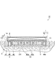
- FIG. 2 is a side sectional view of the coil device according to the first embodiment.
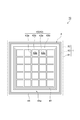
- FIG. 3 is a plan view of a heat dissipation member of the coil device of FIG.
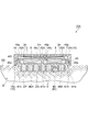
- FIG. 4 is a side sectional view of the coil device according to the second embodiment.
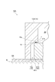
- FIG. 5 is an enlarged view showing a facing surface and a contact surface of the coil device of FIG.
- FIG. 6 is a side sectional view of the coil device according to the third embodiment.
- a coil device is a coil device that is installed on an installation target, and includes a housing that houses at least a coil portion, and a heat dissipation member that is in thermal contact with the installation target, and the heat dissipation member Includes a main body portion interposed at least at a part between the housing and the installation target, and a protrusion protruding from the main body portion toward the installation target.
- the main body portion of the heat dissipation member is interposed at least in part between the housing and the installation target. Therefore, heat from the housing is transmitted to the main body.
- the heat dissipation member is in thermal contact with the installation target.
- the heat dissipation member includes a protrusion that protrudes from the main body portion toward the installation target. Therefore, the heat transmitted to the main body is radiated to the installation target through the protrusion. Thereby, the heat dissipation from a housing
- the protrusion may be a plurality of wall portions protruding from the main body portion toward the installation target.
- the heat radiating area of the heat radiating member is effectively expanded by the plurality of wall portions. Therefore, the cooling performance by natural cooling can be further improved.
- the installation target includes the ground and the ground, at least a part of the wall portion is buried below the ground, and the wall portion includes a plurality of first portions extending along the main body portion.
- the gap defined by the first wall portion and the second wall portion may be filled with a filler, including the wall portion and a plurality of second wall portions intersecting the first wall portion.
- the heat radiation to the ground is realized exclusively by the radiation of heat through the filler filled in the gap. Therefore, the heat radiation to the ground may not use the convection of fluid such as air in the gap. Therefore, the structure of the 1st wall part and 2nd wall part which mutually cross
- the main body part may include a coil support part that supports the coil part, and the coil support part may include an eddy current reduction part that reduces eddy currents generated by the coil part.
- the eddy current generated by the coil part is reduced by the eddy current reducing part, the heat generation of the heat radiating member itself is suppressed. Therefore, the enlargement of the heat radiating member can be suppressed.
- the housing may further contain a circuit board
- the main body may include a circuit board support part that supports the circuit board.
- the circuit board can be accommodated in the housing by the circuit board support portion. Furthermore, the radiation of heat from the circuit board as a heat source to the installation target is promoted through the circuit board support part. Therefore, the circuit board can be efficiently cooled.
- the protrusion amount of the protrusion with respect to the reference surface along the main body may increase from the peripheral edge of the main body toward the center of the main body.
- the external shape of the protrusion of the heat radiating member approaches a three-dimensional shape of a cone having a central axis passing through the central portion of the main body, for example. Therefore, since the heat radiation area of the heat radiating member is substantially increased, the radiation of heat from the heat radiating member to the installation target is promoted compared to the case where the protruding amount is constant. As a result, it is possible to further improve the cooling performance by natural cooling.
- the protrusion may include an installation protrusion that contacts the installation object.
- the installation projection that functions as a heat radiating member can also function as an installation base for installing the coil device on the installation target.
- the housing is box-shaped including an opening that opens to the installation target side, includes a facing surface that extends along an edge of the opening and faces the main body, and the main body includes: You may include the contact surface which contact
- FIG. 1 is a schematic diagram of a non-contact power feeding system including the coil device of the present disclosure.
- FIG. 2 is a side sectional view of the coil device 10 according to the first embodiment.
- the coil device 10 is used for, for example, the power transmission device 101 or the power reception device 102 in the non-contact power feeding system 100.
- the non-contact power supply system 100 is a system for charging a battery mounted on a vehicle V such as an electric vehicle or a hybrid vehicle.
- the coil device 10 will be described by taking the case where the coil device 10 is used for the power transmission device 101 as an example.
- An external power source is connected to the coil device 10 serving as a power transmission coil device via a power transmission circuit, a rectifier circuit, and the like.
- the power transmission circuit, the rectifier circuit, and the like are provided outside the coil device 10, for example.
- the power transmission coil device and the power reception coil device face each other in the vertical direction, and the internal coils are electromagnetically coupled to form an electromagnetic coupling circuit, thereby making contact with the coil of the power transmission coil device from the coil of the power reception coil device. Power is supplied.
- the power receiving coil device receives electric power from the power transmitting coil device in a contactless manner.
- the electromagnetic coupling circuit may be a circuit that supplies power by the “electromagnetic induction method” or may be a circuit that supplies power by the “magnetic resonance method”.
- the coil device 10 has, for example, a flat shape.
- the coil device 10 is installed on the ground GS. At least a part of the coil device 10 is buried below the ground GS.
- the coil device 10 is installed along the installation surface DS in the ground E. That is, the ground GS and the ground E below the ground GS are installation targets on which the coil device 10 is installed.
- the ground GS may include the surface of soil or the surface of a road surface structure such as pavement.
- the ground E is spread below the ground GS.
- the ground E may include soil extending below the ground GS, or may include a portion below the ground GS in a road surface structure such as pavement.
- the heat capacity of the ground E is very large, for example, compared to the heat capacity of the air around the coil device 10.
- the heat capacity of the ground E is stable because it is less affected by changes in the external environment such as seasonal changes.
- the coil device 10 includes a housing 1 and a coil unit 2 accommodated in the housing 1.
- the housing 1 has, for example, a rectangular shape when viewed in the vertical direction (plan view).
- the housing 1 has a base 11 and a cover 12 fixed to the base 11.
- the base 11 is a plate-like member disposed on the installation surface DS side of the housing 1 and ensures the rigidity of the coil device 10 as a whole.
- a surface on the installation surface DS side of the base 11 forms a bottom surface 13 of the housing 1.
- the base 11 is made of, for example, a nonmagnetic material and a conductive material.
- the base 11 is made of a metal having high rigidity and low permeability, and is made of, for example, aluminum. Thereby, the base 11 can shield the outside outflow of the leakage magnetic flux. In other words, the base 11 is a magnetic shield plate.
- the cover 12 is a box disposed on the opposite side of the installation surface DS in the housing 1 and protects interior parts including the coil.
- the cover 12 is made of, for example, a nonmagnetic and nonconductive material, and is made of, for example, an insulating resin.
- the base 11 and the cover 12 form an accommodation space 14 for accommodating the coil portion 2.
- the coil part 2 has at least a coil.
- the coil is, for example, a circular type coil.
- the coil is formed by, for example, a conductive wire wound in a substantially rectangular spiral shape in the same plane.
- As the conducting wire for example, a litz wire in which a plurality of conductor wires insulated from each other are twisted may be used.
- the coil device 10 When the coil device 10 is used for the power transmission device 101, the coil generates a magnetic flux.
- the coil part 2 may further have, for example, a bobbin and a ferrite core.
- the bobbin is a flat coil holding member that holds a conducting wire by winding the conducting wire around the bobbin.
- the bobbin is made of a nonmagnetic and nonconductive material, and is made of, for example, an insulating resin.
- the ferrite core is made of ferrite that is a magnetic substance.
- the coil part 2 for example, a coil, a bobbin, and a ferrite core are integrally disposed in the accommodation space 14 in the housing 1.
- the coil unit 2 is a heating element that generates heat due to Joule heat or the like during power feeding using the coil device 10.
- the coil device 10 includes a heat radiating member 4 that radiates heat generated in the coil portion 2 by natural cooling.
- the heat radiating member 4 is attached to the housing 1 via the heat conducting member 3.
- the heat conducting member 3 enhances the adhesion between the housing 1 and the heat radiating member 4 and facilitates the transfer of heat from the housing 1 to the heat radiating member 4.
- a silicone sheet can be used as the heat conducting member 3.
- the heat radiating member 4 includes a main body 41 provided so as to be interposed between the housing 1 and the installation surface DS, and a plurality of protrusions 42 (so-called heat radiating pins) protruding from the main body 41 toward the installation surface DS. , including.
- the heat radiating member 4 is provided so as to contact (directly) a part of the bottom surface of the housing 1 (the surface facing the installation surface DS).
- the main body portion 41 is a portion that receives heat generated mainly in the coil portion 2 in the heat radiating member 4.
- the main body 41 has, for example, a flat plate shape, and has a rectangular shape when viewed in the vertical direction (plan view).
- the main body 41 extends along the bottom surface 13 of the housing 1 so as to overlap substantially the entire region (projection region of the housing 1) in which the housing 1 is projected in the vertical direction. In the overlapping portion between the main body 41 and the housing 1, heat generated in the coil portion 2 is transmitted to the main body 41.
- the protrusion 42 is a part of the heat dissipation member 4 that mainly radiates heat received from the coil part 2 to the ground E.
- the protrusion 42 is a wall 43 that protrudes from the main body 41 toward the installation surface DS.
- the wall 43 is formed integrally with the main body 41 and radiates heat from the main body 41 to the ground E. That is, the heat dissipation member 4 is in thermal contact with the ground E.
- FIG. 3 is a plan view of the heat dissipating member 4 of the coil device 10 of FIG.
- the wall portion 43 includes a plurality of first wall portions 43 a extending along the main body portion 41, and a plurality of second wall portions 43 b that intersect the first wall portion 43 a. ,including.
- the first wall portion 43 a is a flat plate extending along the first direction along the main body portion 41.
- the first direction may be, for example, a direction along one side of the outer edge of the main body 41 (one side of the rectangular shape).
- the plurality of first wall portions 43a extend substantially parallel to each other. The lengths of the plurality of first wall portions 43a are substantially equal.
- the plurality of first wall portions 43a protrude substantially perpendicular to the surface of the main body portion 41 on the installation surface DS side.
- the plurality of first wall portions 43a may protrude so as to be inclined at a predetermined angle with respect to the surface of the main body portion 41 on the installation surface DS side.
- the second wall portion 43b is a flat plate extending along a second direction that is a direction along the main body portion 41 and perpendicular to the first direction.
- the plurality of second wall portions 43b extend substantially parallel to each other.
- the lengths of the plurality of second wall portions 43b are substantially equal.
- the plurality of second wall portions 43b protrude substantially perpendicular to the surface of the main body portion 41 on the installation surface DS side.
- the plurality of second wall portions 43b may protrude so as to be inclined at a predetermined angle with respect to the surface of the main body portion 41 on the installation surface DS side.
- Both end portions of the second wall portion 43b are arranged at the same positions as both end portions of the first wall portion 43a. Therefore, the first wall portion 43a and the second wall portion 43b form a lattice shape when viewed in the vertical direction (plan view).
- the first wall 43a and the second wall 43b define a plurality of gaps 43c. Each of the gaps 43 c is filled with the filler 5.
- the filler 5 is a member for facilitating the transfer of the heat of the wall 43 to the ground E.
- the filler 5 is a member having higher heat conductivity than soil or the like constituting the ground E.
- the protrusion 42 includes an installation protrusion 44 that contacts the installation surface DS.
- the protrusion amount of the installation protrusion 44 with respect to the main body portion 41 is larger than the protrusion amount of the protrusion 42 with respect to the main body portion 41.
- the installation protrusion 44 functions as the heat dissipation member 4 and also functions as an installation base for installing the coil device 10 on the ground GS.
- the installation protrusion 44 is arranged in a rectangular frame shape surrounding the wall portion 43 as viewed in the vertical direction, for example.
- the installation protrusion 44 is configured by combining, for example, metal members (for example, aluminum channel material) having a U-shaped cross section in a frame shape.
- the installation protrusion 44 is placed on the installation surface DS such that, for example, a U-shaped (U-shaped) cross section opens toward the installation surface DS.
- a space 44 a in the cross section of the installation protrusion 44 is filled with the filler 5 described above.
- the coil device 10 configured as described above is installed on the ground GS such that at least a part of the wall 43 of the heat radiating member 4 is buried below the ground GS.
- the installation projection 44 is fixed to the installation surface DS so that the frame of the installation projection 44 is in a horizontal plane while being in contact with the installation surface DS.
- the installation surface DS corresponds to the bottom of the depression DP provided at a predetermined depth from the ground GS.
- the coil apparatus 10 is installed in the ground GS by mounting the main-body part 41, the heat conductive member 3, and the housing
- the main body portion 41 of the heat radiating member 4 is interposed at least partially between the housing 1 and the installation surface DS. Therefore, heat from the housing 1 is transmitted to the main body 41.
- the heat dissipation member 4 is in thermal contact with the ground GS.
- the heat dissipation member 4 includes a protrusion 42 that protrudes from the main body 41 toward the installation surface DS. Therefore, the heat transmitted to the main body 41 is radiated to the ground E through the protrusions 42.
- the heat capacity of the ground E is very large, for example, compared with the heat capacity of the air around the coil device 10.
- the heat capacity of the ground E is stable because it is less affected by changes in the external environment such as seasonal changes.
- fever to the ground E is advantageous compared with the thermal radiation of the heat
- FIG. As a result, heat dissipation from the housing 1 to the ground E is promoted. Therefore, according to the coil apparatus 10, it becomes possible to improve the cooling performance by natural cooling.
- the protrusions 42 are a plurality of wall portions 43 that protrude from the main body portion 41 toward the installation surface DS.
- the heat radiation area of the heat radiation member 4 is effectively expanded by the plurality of wall portions 43. Therefore, the cooling performance by natural cooling can be further improved.
- the installation object where the coil apparatus 10 is installed includes the ground GS and the ground E below the ground GS. At least a part of the wall 43 is buried below the ground GS.
- the wall part 43 includes a plurality of first wall parts 43a extending along the main body part 41 and a plurality of second wall parts 43b intersecting the first wall part 43a.
- Filler 5 is filled in a gap 43c defined by the first wall 43a and the second wall 43b.
- heat radiation to the ground E is realized exclusively by heat radiation through the filler 5 filled in the gap 43c. Therefore, the heat radiation to the ground E may not use the convection of fluid such as air in the gap 43c. Therefore, the structure of the 1st wall part 43a and the 2nd wall part 43b which mutually cross
- the protrusion 42 includes an installation protrusion 44 that contacts the installation surface DS.
- the installation protrusion 44 that functions as the heat radiating member 4 can also function as an installation base for installing the coil device 10 on the ground GS.
- FIG. 4 is a side sectional view of the coil device 10A according to the second embodiment.
- the coil device 10A differs from the coil device 10 of the first embodiment mainly in that the housing 1A does not include the base 11 and further accommodates the circuit board 6, and the heat dissipation member 4A.
- the main body portion 41 ⁇ / b> A includes a coil support portion 45 ⁇ / b> A that supports the coil portion 2 and a circuit board support portion 46 ⁇ / b> A that supports the circuit board 6.
- the protrusion 42 of the heat radiating member 4A is configured in the same manner as the protrusion 42 of the heat radiating member 4 of the first embodiment.
- the housing 1 ⁇ / b> A includes a box-shaped cover 12 ⁇ / b> A including an opening 15 that opens to the installation surface DS instead of the cover 12.
- the housing 1A has, for example, a rectangular shape (planar shape) when viewed in the vertical direction.
- the edge 15a of the opening 15 has, for example, a rectangular shape smaller than the planar shape of the housing 1A when viewed in the vertical direction (plan view).
- the housing 1A further accommodates a circuit board 6.
- the circuit board 6 includes, for example, a power transmission circuit including a capacitor, a rectifier circuit including an inverter that converts DC power into AC power (high-frequency power), and a control circuit that controls power supply from the power transmission apparatus 101 to the power reception apparatus 102 in FIG. Etc.
- the heat radiating member 4A is disposed in the opening 15 of the cover 12A.
- the heat radiating member 4 ⁇ / b> A is provided so that the main body 41 ⁇ / b> A covers the opening 15.
- the main body 41A overlaps with substantially the entire projection area of the housing 1A in the vertical direction (plan view).
- the outer edge of the main body 41 ⁇ / b> A reaches the edge 15 a of the opening 15 in the vertical direction (plan view). That is, the main body 41A is provided so as to be interposed at least at a part between the housing 1A and the installation surface DS.
- the main body 41A may extend to the outside of the projection area of the housing 1A.
- the main body 41A does not necessarily overlap with substantially the entire projection area of the housing 1A, and may overlap with at least a part of the projection area of the housing 1A.
- a housing space 14 for housing the coil unit 2 and the circuit board 6 is formed by the cover 12A and the main body unit 41A.
- the main body portion 41 ⁇ / b> A has a plurality of coil support portions 45 ⁇ / b> A that support the coil portion 2.
- the main body portion 41 ⁇ / b> A includes a plurality of circuit board support portions 46 ⁇ / b> A that support the circuit board 6.
- Each of the coil support portion 45A and the circuit board support portion 46A may be formed integrally with the main body portion 41A by, for example, aluminum casting.
- the coil support part 45A has a flat plate part 45p that supports the coil part 2 at the tip part 45t, while projecting to the opposite side of the protrusion 42 in the main body part 41A.
- the coil support portion 45A is arranged at a plurality of locations including the peripheral edge portion 41n and the central portion 41m of the main body portion 41A so that the flat plate portion 45p supports the edge portion 2e and the central portion 2m of the coil portion 2.
- Such a coil support portion 45 ⁇ / b> A can support the coil portion 2 as a whole and receive heat generated in the coil portion 2 more directly.
- the circuit board support 46A is provided at the bottom 46u of a box-shaped space defined by being sandwiched by a plurality of coil supports 45A.
- the circuit board support portion 46A is a flat plate portion 46p that extends substantially parallel to the flat plate portion 45p of the coil support portion 45A at the bottom 46u of the space.
- Each of the plurality of circuit board support portions 46 ⁇ / b> A supports each of the plurality of circuit boards 6.
- Such a circuit board support 46 ⁇ / b> A can support the circuit board 6 and more directly receive the heat generated by the circuit board 6.
- the circuit board support 46A can be accessed through an opening surrounded by the edge of the flat plate portion 45p of the coil support 45A.
- the opening may be provided with a lid made of, for example, aluminum.
- the lid functions as a magnetic shield plate that suppresses the magnetic flux from the coil portion 2 from interlinking with the circuit board 6.
- the cover 12 ⁇ / b> A includes a facing surface 16 that faces the main body 41 ⁇ / b> A of the heat radiating member 4 ⁇ / b> A at the edge 15 a of the opening 15.
- the facing surface 16 extends along the edge 15a of the opening 15 so as to exhibit a rectangular shape, for example, when viewed in the vertical direction (plan view).
- a groove 16 a extending along the edge 15 a of the opening 15 is formed in the facing surface 16.
- the sealing material 7 is fitted into the groove 16a.
- a rubber O-ring having a shape corresponding to the groove 16a can be used.
- the main body portion 41 ⁇ / b> A includes a contact surface 41 s that contacts the opposing surface 16.
- the contact surface 41 s is in contact with the opposing surface 16 over the entire edge 15 a of the opening 15. Thereby, since the opposing surface 16 and the contact surface 41s contact each other, the force acting on the housing 1A can be transmitted to the main body portion 41A.
- the contact surface 41 s may contact the opposing surface 16 via the seal material 7.
- the housing 1 ⁇ / b> A further accommodates the circuit board 6.
- the main body portion 41 ⁇ / b> A includes a circuit board support portion 46 ⁇ / b> A that supports the circuit board 6.
- the circuit board 6 can be accommodated in the housing 1A by the circuit board support 46A. Furthermore, the radiation of heat from the circuit board 6 as the heat source to the ground E is promoted via the circuit board support 46A. Therefore, the circuit board 6 can be efficiently cooled.
- the housing 1A has a box shape including an opening 15 that opens toward the installation surface DS.
- the housing 1A includes a facing surface 16 that extends along the edge 15a of the opening 15 and faces the main body 41A.
- the main body portion 41 ⁇ / b> A is provided so as to cover the opening 15, and includes a contact surface 41 s that contacts the facing surface 16.
- FIG. 6 is a side sectional view of a coil device 10B according to the third embodiment.
- the coil device 10B is different from the coil device 10A of the second embodiment mainly in that the main body portion 41B of the heat dissipation member 4B has a coil support portion 45B including an eddy current reduction portion 47 instead of the coil support portion 45A.
- the main body portion 41B has a circuit board support portion 46B that is different from the circuit board support portion 46A in place of the circuit board support portion 46A, and the heat radiation member 4B.
- the projection 42 is a wall portion 43 ⁇ / b> B that is different from the wall portion 43 and has a different protruding form from the wall portion 43.
- the cover 12B of the housing 1B is configured in the same manner as the cover 12A of the second embodiment.
- the housing 1B and the main body 41B have the same configuration as the facing surface 16 and the contact surface 41s of the second embodiment.
- the coil support part 45B includes an eddy current reduction part 47 that reduces the eddy current generated by the coil 2a of the coil part 2.
- the eddy current reduction part 47 changes the state of the eddy current that can occur in the coil support part 45B.
- the eddy current reducing unit 47 blocks a part of the eddy current generated by the magnetic flux of the coil 2a.
- the eddy current reduction part 47 is provided in the recessed part 45c formed in the coil support part 45B.
- the recess 45c is provided in a lower range of the coil support portion 45B (a portion where the magnetic flux of the coil 2a is easily interlinked).
- a laminated body 47m may be disposed as the eddy current reduction unit 47.
- a strip-shaped metal plate having a width corresponding to the depth of the recess 45c may be laminated.
- the laminated body 47m is fitted in the recess 45c so that the lamination direction is a direction along the surface of the coil support part 45B.
- the eddy current reduction unit 47 is not limited to this form, and various configurations that block a part of the eddy current generated by the magnetic flux of the coil 2a can be employed.
- a slit formed in the coil support part 45 ⁇ / b> B, a through hole formed in the coil support part 45 ⁇ / b> B, or the like can be employed as the eddy current reduction part 47.
- the eddy current generated in the eddy current reduction unit 47 by the magnetic flux of the coil 2a is more than the eddy current generated in the coil support unit 45B when the recess 45c and the eddy current reduction unit 47 are not formed in the coil support unit 45B. It becomes possible to make it smaller.
- the circuit board support portion 46B is provided below the central portion 2m of the coil portion 2.
- the circuit board support portion 46B is a flat plate portion 46p that extends substantially parallel to the flat plate portion 45p of the coil support portion 45B at the bottom of the recess 2d provided in the region 2c surrounded by the coil 2a.
- the circuit board support part 46B can support the circuit board 6 and receive the heat generated in the circuit board 6 more directly.
- the circuit board support 46B is separated from the innermost coil 2a by a predetermined distance or more. Therefore, the magnetic flux generated from the coil 2a is not easily interlinked with the circuit board support 46B. In this case, it is possible to omit covering the recess 2d provided in the region 2c surrounded by the coil 2a with a lid that functions as a magnetic shield plate.
- the wall 43B serving as the protrusion 42 has a different protrusion from the wall 43 of the first and second embodiments. Specifically, the protruding amount of the wall portion 43B with respect to the reference plane GL along the main body portion 41B increases from the peripheral edge portion 41n of the main body portion 41B toward the central portion 41m of the main body portion 41B.
- the reference plane GL is a virtual plane that serves as a reference for defining the protruding amount of the wall 43B regardless of the shape of the main body 41B.
- the reference surface GL may be a plane substantially parallel to the installation surface DS.
- the reference plane GL is a virtual plane including a contact portion between the main body 41B and the ground GS.
- the reference plane GL may be a virtual plane along a part of the surface of the main body portion 41B, or may be a virtual plane passing through the inside of the main body portion 41B.
- the outer shape of the wall portion 43B approaches, for example, the three-dimensional shape of the cone 43V as compared with the case where the protruding amount with respect to the reference plane GL is constant.
- the cone 43V has a central axis L that passes through the central portion 41m of the main body portion 41B.
- the cone 43V has a shape corresponding to the outer shape of the main body 41B when viewed in the vertical direction (plan view).
- the pyramid 43V is a quadrangular pyramid, for example, when the outer shape is rectangular.
- the cone 43V is, for example, a cone when the outer shape is circular.
- the heat radiation area of the heat radiation member 4B increases.
- the heat dissipation surface 4s of the heat dissipation member 4B corresponds to the side surface of the cone 43V having the central axis L. Therefore, in the heat radiating member 4B, since the area of the heat radiating surface 4s increases compared to the case where the protrusion amount of the protrusion 42 with respect to the reference surface GL is constant, the heat radiating area of the heat radiating member 4B substantially increases. Thereby, the radiation range of the heat from the heat radiating member 4B becomes a wide range compared with the case where the protrusion amount of the protrusion 42 with respect to the reference plane GL is constant.
- the main body portion 41 ⁇ / b> B includes a coil support portion 45 ⁇ / b> B that supports the coil portion 2.
- the coil support part 45 ⁇ / b> B includes an eddy current reducing part 47 that reduces eddy currents generated by the coil 2 a of the coil part 2.
- the energy loss (eddy current loss) due to the eddy current depends on, for example, the maximum magnetic flux density around the coil 2a and the thickness of the conductor.
- the parameters related to the magnetic flux density are directly related to the power transmission / reception performance of the coil device 10, it is difficult to change them.
- the eddy current reduction unit 47 in the coil support part 45B that supports the coil 2a, the eddy current generated by the coil 2a can be reduced by the eddy current reduction unit 47.
- the eddy current reduction unit 47 since heat generation of the heat radiating member 4B itself is suppressed, an increase in size of the heat radiating member 4B can be suppressed.
- the protruding amount of the wall portion 43B with respect to the reference plane GL along the main body portion 41B increases from the peripheral edge portion 41n of the main body portion 41B toward the central portion 41m of the main body portion 41B.
- the external shape of the wall part 43B of the heat radiating member 4B approaches the three-dimensional shape of the cone 43V.
- the cone 43V has a central axis L that passes through the central portion 41m of the main body portion 41B.
- the cone 43V is, for example, a cone. Therefore, compared with the case where the protrusion amount of the protrusion 42 with respect to the reference plane GL is constant, the heat dissipation area of the heat dissipation member 4B is substantially increased.
- the coil device 10 may be used for the power receiving device 102.
- the coil device 10 as the power receiving coil device is installed, for example, at the bottom of the chassis of the vehicle V or the like.
- the heat radiating member 4 may radiate heat from the housing 1 to the chassis of the vehicle V by a plurality of protrusions 42 that protrude from the main body portion 41 toward the bottom of the chassis of the vehicle V.
- the wall portion 43 including the first wall portion 43a and the second wall portion 43b that intersect with each other is illustrated as the protrusion 42 of the heat dissipation member 4, but is not limited thereto.
- the wall 43 may be configured so that convection of a fluid such as air can be used in some gaps 43c.
- the protrusions 42 are a plurality of wall portions 43 protruding from the main body portion 41 toward the installation surface DS.
- the protrusions 42 are a plurality of columnar heat dissipation pins protruding from the main body portion 41 toward the installation surface DS. May be.
- the main body 41 overlaps substantially the entire region (projection region of the housing 1) in which the housing 1 is projected in the vertical direction, but may extend to the outside of the projection region of the housing 1. .
- the main body 41 does not necessarily overlap with the substantially entire projection area of the housing 1. In short, the main body 41 only has to overlap with at least a part of the projection area of the housing 1.
- only the installation projection 44 contacts the installation surface DS.
- the coil 2a of the third embodiment is a so-called circular coil, but may be a solenoid type coil.
- the coil device 10 used in the non-contact power feeding system 100 for charging a battery mounted on the vehicle V has been described as an example, but the present invention is not limited to this.
- the coil device 10 can be modified into various forms as long as heat is radiated from the housing 1 to the installation target by the heat dissipation member 4 by being installed on the installation target.
Landscapes
- Engineering & Computer Science (AREA)
- Power Engineering (AREA)
- Transportation (AREA)
- Mechanical Engineering (AREA)
- Computer Networks & Wireless Communication (AREA)
- Coils Of Transformers For General Uses (AREA)
- Cooling Or The Like Of Electrical Apparatus (AREA)
- Transformer Cooling (AREA)
- Electric Propulsion And Braking For Vehicles (AREA)
Abstract
Description
以下、本開示の実施形態について、図面を参照しながら説明する。なお、図面の説明において同一要素には同一符号を付し、重複する説明は省略する。
図4及び図5を参照して、第2実施形態に係るコイル装置について説明する。図4は、第2実施形態に係るコイル装置10Aの側断面図である。コイル装置10Aが第1実施形態のコイル装置10と違う点は、主に、筐体1Aが、ベース11を含んでおらず、回路基板6を更に収容している点、及び、放熱部材4Aの本体部41Aが、コイル部2を支持するコイル支持部45Aと、回路基板6を支持する回路基板支持部46Aと、を含んでいる点である。なお、放熱部材4Aの突起42は、第1実施形態の放熱部材4の突起42と同様に構成されている。
図6を参照して、第3実施形態に係るコイル装置について説明する。図6は、第3実施形態に係るコイル装置10Bの側断面図である。コイル装置10Bが第2実施形態のコイル装置10Aと違う点は、主に、放熱部材4Bの本体部41Bが、コイル支持部45Aに代えて、渦電流低減部47を含むコイル支持部45Bを有している点と、本体部41Bが、回路基板支持部46Aに代えて、コイル部2に対する配置が回路基板支持部46Aとは異なる回路基板支持部46Bを有している点と、放熱部材4Bの突起42が、壁部43に代えて、壁部43とは突出の態様が異なる壁部43Bである点と、である。なお、筐体1Bのカバー12Bは、第2実施形態のカバー12Aと同様に構成されている。筐体1B及び本体部41Bは、第2実施形態の対向面16及び当接面41sと同様の構成を有している。
2 コイル部
4、4A、4B 放熱部材
5 充填材
6 回路基板
10、10A、10B コイル装置
15 開口部
15a 縁
16 対向面
41、41A、41B 本体部
41n 周縁部
41m 中央部
41s 当接面
42 突起
43、43B 壁部
43a 第1壁部
43b 第2壁部
43c 間隙
44 設置用突起
45A、45B コイル支持部
46A、46B 回路基板支持部
47 渦電流低減部
DS 設置面(設置対象)
E 地盤(設置対象)
GL 基準面
GS 地面(設置対象)
V 車両(設置対象)
Claims (8)
- 設置対象に設置されるコイル装置であって、
少なくともコイル部を収容する筐体と、
前記設置対象と熱的に接触する放熱部材と、を備え、
前記放熱部材は、前記筐体と前記設置対象との間の少なくとも一部に介在する本体部と、前記本体部から前記設置対象に向かって突出する突起と、を含む、コイル装置。 - 前記突起は、前記本体部から前記設置対象に向かって突出する複数の壁部である、請求項1に記載のコイル装置。
- 前記設置対象は、地面及び前記地面よりも下方の地盤を含み、
前記壁部の少なくとも一部は、前記地面よりも下に埋没されており、
前記壁部は、前記本体部に沿って延在する複数の第1壁部と、前記第1壁部に交差する複数の第2壁部とを含み、
前記第1壁部及び前記第2壁部で画成される間隙には、充填材が充填されている、請求項2に記載のコイル装置。 - 前記本体部は、前記コイル部を支持するコイル支持部を含み、
前記コイル支持部は、前記コイル部により発生させられる渦電流を低減する渦電流低減部を含む、請求項1~3の何れか一項に記載のコイル装置。 - 前記筐体は、回路基板を更に収容し、
前記本体部は、前記回路基板を支持する回路基板支持部を含む、請求項1~4の何れか一項に記載のコイル装置。 - 前記本体部に沿う基準面に対する前記突起の突出量は、前記本体部の周縁部から前記本体部の中央部に向かうに従って大きくなる、請求項1~5の何れか一項に記載のコイル装置。
- 前記突起は、前記設置対象に接触する設置用突起を含む、請求項1~6の何れか一項に記載のコイル装置。
- 前記筐体は、前記設置対象側に開口する開口部を含む箱状であり、前記開口部の縁に沿って延在すると共に前記本体部に対向する対向面を含み、
前記本体部は、前記開口部の前記縁において前記対向面と当接する当接面を含む、請求項1~7の何れか一項に記載のコイル装置。
Priority Applications (3)
| Application Number | Priority Date | Filing Date | Title |
|---|---|---|---|
| CN201980018164.8A CN111837207A (zh) | 2018-05-17 | 2019-03-04 | 线圈装置 |
| GB2015779.8A GB2586737B (en) | 2018-05-17 | 2019-03-04 | Coil device |
| US17/046,360 US11328852B2 (en) | 2018-05-17 | 2019-03-04 | Coil device |
Applications Claiming Priority (2)
| Application Number | Priority Date | Filing Date | Title |
|---|---|---|---|
| JP2018-095416 | 2018-05-17 | ||
| JP2018095416A JP7087664B2 (ja) | 2018-05-17 | 2018-05-17 | コイル装置 |
Publications (1)
| Publication Number | Publication Date |
|---|---|
| WO2019220744A1 true WO2019220744A1 (ja) | 2019-11-21 |
Family
ID=68540086
Family Applications (1)
| Application Number | Title | Priority Date | Filing Date |
|---|---|---|---|
| PCT/JP2019/008437 Ceased WO2019220744A1 (ja) | 2018-05-17 | 2019-03-04 | コイル装置 |
Country Status (5)
| Country | Link |
|---|---|
| US (1) | US11328852B2 (ja) |
| JP (1) | JP7087664B2 (ja) |
| CN (1) | CN111837207A (ja) |
| GB (1) | GB2586737B (ja) |
| WO (1) | WO2019220744A1 (ja) |
Families Citing this family (8)
| Publication number | Priority date | Publication date | Assignee | Title |
|---|---|---|---|---|
| DE102016219476A1 (de) * | 2016-10-07 | 2018-04-12 | Bayerische Motoren Werke Aktiengesellschaft | Induktive Ladeeinheit für ein Fahrzeug |
| DE102018203557A1 (de) * | 2018-03-08 | 2019-09-12 | Mahle International Gmbh | Induktionsladevorrichtung |
| US11874423B2 (en) | 2019-10-25 | 2024-01-16 | Witricity Corporation | Circuit for object detection and vehicle position determination |
| CN110880803B (zh) | 2019-12-17 | 2022-02-15 | 台达电子企业管理(上海)有限公司 | 无线充电装置 |
| JP7517143B2 (ja) * | 2020-12-28 | 2024-07-17 | トヨタ自動車株式会社 | リアクトルユニット |
| WO2022164558A1 (en) * | 2021-01-26 | 2022-08-04 | Witricity Corporation | Wire-wound structures for electromagnetic sensing of objects |
| DE102021205980A1 (de) * | 2021-06-11 | 2022-12-15 | Mahle International Gmbh | Bodenbaugruppe für eine induktive Ladevorrichtung |
| DE102023201210A1 (de) * | 2023-02-14 | 2024-08-14 | Siemens Aktiengesellschaft | Vorrichtung zum induktiven Laden einer Batterie eines Kraftfahrzeugs |
Citations (7)
| Publication number | Priority date | Publication date | Assignee | Title |
|---|---|---|---|---|
| JP2012044049A (ja) * | 2010-08-20 | 2012-03-01 | Stanley Electric Co Ltd | ヒートシンク |
| JP2013147142A (ja) * | 2012-01-19 | 2013-08-01 | Yazaki Corp | コイルユニットの設置構造 |
| JP2015153929A (ja) * | 2014-02-17 | 2015-08-24 | 株式会社デンソー | リアクトル |
| JP2016076636A (ja) * | 2014-10-08 | 2016-05-12 | カルソニックカンセイ株式会社 | 半導体冷却装置の製造方法および半導体冷却装置 |
| JP2016143773A (ja) * | 2015-02-02 | 2016-08-08 | 株式会社Ihi | コイル装置の取付構造およびコイル装置 |
| JP2016171238A (ja) * | 2015-03-13 | 2016-09-23 | 株式会社デンソー | 放熱装置 |
| WO2016194739A1 (ja) * | 2015-06-04 | 2016-12-08 | 株式会社Ihi | コイル装置 |
Family Cites Families (30)
| Publication number | Priority date | Publication date | Assignee | Title |
|---|---|---|---|---|
| US6062302A (en) * | 1997-09-30 | 2000-05-16 | Lucent Technologies Inc. | Composite heat sink |
| US7126450B2 (en) * | 1999-06-21 | 2006-10-24 | Access Business Group International Llc | Inductively powered apparatus |
| US7046111B2 (en) * | 2002-11-18 | 2006-05-16 | Illinoise Tool Works Inc. | Inductor assembly |
| JP2004168867A (ja) * | 2002-11-19 | 2004-06-17 | Kyocera Chemical Corp | 熱伝導シート |
| JP4608282B2 (ja) | 2004-10-28 | 2011-01-12 | 大日本印刷株式会社 | 非接触給電方法及び装置 |
| US8169185B2 (en) * | 2006-01-31 | 2012-05-01 | Mojo Mobility, Inc. | System and method for inductive charging of portable devices |
| JP5254670B2 (ja) | 2008-06-11 | 2013-08-07 | 三菱重工業株式会社 | 車両用受電装置 |
| KR100944113B1 (ko) | 2009-02-27 | 2010-02-24 | 한국과학기술원 | 전기자동차용 전원공급 시스템 및 방법 |
| CN201897255U (zh) * | 2010-08-18 | 2011-07-13 | 范福仓 | 电感应式取暖器 |
| JP2012204440A (ja) * | 2011-03-24 | 2012-10-22 | Nitto Denko Corp | 無線電力伝送用磁気素子及びその製造方法 |
| CN103828189A (zh) * | 2011-07-26 | 2014-05-28 | Lg伊诺特有限公司 | 无线功率发射机和无线功率接收机 |
| DE102011088218B4 (de) * | 2011-12-12 | 2015-10-15 | Robert Bosch Gmbh | Elektronisches Leistungsmodul mit thermischen Kopplungsschichten zu einem Entwärmungselement und Verfahren zur Herstellung |
| EP2833508B1 (en) | 2012-03-28 | 2017-11-15 | Fuji Machine Mfg. Co., Ltd. | Non-contact power supply apparatus |
| JP6325186B2 (ja) * | 2012-08-23 | 2018-05-16 | 積水ポリマテック株式会社 | 熱伝導性シート |
| WO2014057587A1 (ja) | 2012-10-12 | 2014-04-17 | 株式会社日立エンジニアリング・アンド・サービス | 非接触給電装置 |
| JP5634477B2 (ja) * | 2012-10-19 | 2014-12-03 | 三菱電機株式会社 | コイル装置 |
| KR101345703B1 (ko) | 2013-03-11 | 2013-12-30 | 주식회사 원진일렉트로닉스 | 차량의 블로어 모터 구동기용 히트싱크 |
| JP5374657B1 (ja) | 2013-03-21 | 2013-12-25 | 東亜道路工業株式会社 | 舗装構造体及び舗装構造体の施工方法 |
| JP2015002285A (ja) * | 2013-06-17 | 2015-01-05 | 富士通株式会社 | コイル装置、電子装置及びコイル装置の制御方法 |
| JP2015207741A (ja) * | 2014-04-23 | 2015-11-19 | トヨタ自動車株式会社 | リアクトル |
| WO2015199151A1 (ja) * | 2014-06-25 | 2015-12-30 | 株式会社Ihi | コイル装置およびインダクタンス変更機構 |
| KR20160050950A (ko) * | 2014-10-31 | 2016-05-11 | 현대모비스 주식회사 | 인덕터 방열 장치를 구비하는 dc-dc 컨버터 |
| JP6395095B2 (ja) * | 2015-03-11 | 2018-09-26 | パナソニックIpマネジメント株式会社 | 非接触給電装置および非接触給電システム |
| WO2016190456A1 (ko) * | 2015-05-22 | 2016-12-01 | 한국과학기술원 | 온라인 전기자동차용 몰드식 s형 급전모듈 |
| JP2017034029A (ja) | 2015-07-30 | 2017-02-09 | 日本特殊陶業株式会社 | 共振器 |
| JP2017050334A (ja) * | 2015-08-31 | 2017-03-09 | トヨタ自動車株式会社 | リアクトル |
| US20170129344A1 (en) * | 2015-11-06 | 2017-05-11 | Qualcomm Incorporated | Methods and apparatus for thermal dissipation in vehicle pads for wireless power transfer applications |
| KR101727465B1 (ko) | 2016-07-18 | 2017-04-17 | 주식회사 서연전자 | 차량용 무선충전 장치 |
| JP6606047B2 (ja) | 2016-10-03 | 2019-11-13 | 株式会社東芝 | 送電装置 |
| CN110914936A (zh) * | 2017-05-24 | 2020-03-24 | 株式会社自动网络技术研究所 | 电路结构体 |
-
2018
- 2018-05-17 JP JP2018095416A patent/JP7087664B2/ja active Active
-
2019
- 2019-03-04 US US17/046,360 patent/US11328852B2/en active Active
- 2019-03-04 CN CN201980018164.8A patent/CN111837207A/zh active Pending
- 2019-03-04 GB GB2015779.8A patent/GB2586737B/en active Active
- 2019-03-04 WO PCT/JP2019/008437 patent/WO2019220744A1/ja not_active Ceased
Patent Citations (7)
| Publication number | Priority date | Publication date | Assignee | Title |
|---|---|---|---|---|
| JP2012044049A (ja) * | 2010-08-20 | 2012-03-01 | Stanley Electric Co Ltd | ヒートシンク |
| JP2013147142A (ja) * | 2012-01-19 | 2013-08-01 | Yazaki Corp | コイルユニットの設置構造 |
| JP2015153929A (ja) * | 2014-02-17 | 2015-08-24 | 株式会社デンソー | リアクトル |
| JP2016076636A (ja) * | 2014-10-08 | 2016-05-12 | カルソニックカンセイ株式会社 | 半導体冷却装置の製造方法および半導体冷却装置 |
| JP2016143773A (ja) * | 2015-02-02 | 2016-08-08 | 株式会社Ihi | コイル装置の取付構造およびコイル装置 |
| JP2016171238A (ja) * | 2015-03-13 | 2016-09-23 | 株式会社デンソー | 放熱装置 |
| WO2016194739A1 (ja) * | 2015-06-04 | 2016-12-08 | 株式会社Ihi | コイル装置 |
Also Published As
| Publication number | Publication date |
|---|---|
| JP2019201130A (ja) | 2019-11-21 |
| US20210151238A1 (en) | 2021-05-20 |
| CN111837207A (zh) | 2020-10-27 |
| US11328852B2 (en) | 2022-05-10 |
| GB2586737B (en) | 2022-05-25 |
| GB202015779D0 (en) | 2020-11-18 |
| GB2586737A (en) | 2021-03-03 |
| JP7087664B2 (ja) | 2022-06-21 |
Similar Documents
| Publication | Publication Date | Title |
|---|---|---|
| JP7087664B2 (ja) | コイル装置 | |
| CN107408453B (zh) | 非接触电力传输用线圈单元 | |
| US10847310B2 (en) | Coil unit, and power transmitting device, power receiving device and wireless power transmission system using the coil unit | |
| JP5921839B2 (ja) | 非接触給電トランス | |
| CN110419085B (zh) | 变压器 | |
| JP5762508B2 (ja) | 電力変換装置 | |
| US10804709B2 (en) | Coil unit, and power transmitting device, power receiving device and wireless power transmission system using the coil unit | |
| US10840014B2 (en) | Coil unit, and power transmitting device, power receiving device and wireless power transmission system using the coil unit | |
| JP2015222751A (ja) | コイル装置 | |
| JP6405903B2 (ja) | コイルユニット | |
| JPWO2014119294A1 (ja) | 非接触電力伝送装置用コイル及び非接触電力伝送装置 | |
| JP2016103613A (ja) | コイルユニット | |
| JPH11345724A (ja) | 磁気漏洩形高周波トランスとこれを使用するインバータ回路 | |
| WO2012102008A1 (ja) | 非接触給電システムに用いられるコイルユニット | |
| JP6570982B2 (ja) | リアクトル | |
| WO2014147985A1 (ja) | 非接触充電装置 | |
| JP5523597B1 (ja) | 電力変換装置 | |
| JP2023041422A (ja) | コイルユニット | |
| JP2023041423A (ja) | コイルユニット | |
| JP2000114758A (ja) | 電源装置 | |
| JP7204807B2 (ja) | 内燃機関用点火コイル装置 | |
| JP2017034029A (ja) | 共振器 | |
| JP6619195B2 (ja) | リアクトル | |
| JP2020078245A (ja) | コイルユニット及びこれを用いた送電装置、受電装置並びにワイヤレス電力伝送システム | |
| JP5939857B2 (ja) | 光源装置 |
Legal Events
| Date | Code | Title | Description |
|---|---|---|---|
| 121 | Ep: the epo has been informed by wipo that ep was designated in this application |
Ref document number: 19804490 Country of ref document: EP Kind code of ref document: A1 |
|
| ENP | Entry into the national phase |
Ref document number: 202015779 Country of ref document: GB Kind code of ref document: A Free format text: PCT FILING DATE = 20190304 |
|
| NENP | Non-entry into the national phase |
Ref country code: DE |
|
| 122 | Ep: pct application non-entry in european phase |
Ref document number: 19804490 Country of ref document: EP Kind code of ref document: A1 |