WO2019189883A1 - チャンバ構造 - Google Patents
チャンバ構造 Download PDFInfo
- Publication number
- WO2019189883A1 WO2019189883A1 PCT/JP2019/014336 JP2019014336W WO2019189883A1 WO 2019189883 A1 WO2019189883 A1 WO 2019189883A1 JP 2019014336 W JP2019014336 W JP 2019014336W WO 2019189883 A1 WO2019189883 A1 WO 2019189883A1
- Authority
- WO
- WIPO (PCT)
- Prior art keywords
- robot
- transfer
- chamber
- transfer chamber
- flange
- Prior art date
- Legal status (The legal status is an assumption and is not a legal conclusion. Google has not performed a legal analysis and makes no representation as to the accuracy of the status listed.)
- Ceased
Links
Images




Classifications
-
- H—ELECTRICITY
- H10—SEMICONDUCTOR DEVICES; ELECTRIC SOLID-STATE DEVICES NOT OTHERWISE PROVIDED FOR
- H10P—GENERIC PROCESSES OR APPARATUS FOR THE MANUFACTURE OR TREATMENT OF DEVICES COVERED BY CLASS H10
- H10P72/00—Handling or holding of wafers, substrates or devices during manufacture or treatment thereof
- H10P72/04—Apparatus for manufacture or treatment
- H10P72/0451—Apparatus for manufacturing or treating in a plurality of work-stations
- H10P72/0464—Apparatus for manufacturing or treating in a plurality of work-stations characterised by the construction of the transfer chamber
-
- H—ELECTRICITY
- H10—SEMICONDUCTOR DEVICES; ELECTRIC SOLID-STATE DEVICES NOT OTHERWISE PROVIDED FOR
- H10P—GENERIC PROCESSES OR APPARATUS FOR THE MANUFACTURE OR TREATMENT OF DEVICES COVERED BY CLASS H10
- H10P30/00—Ion implantation into wafers, substrates or parts of devices
- H10P30/20—Ion implantation into wafers, substrates or parts of devices into semiconductor materials, e.g. for doping
-
- H—ELECTRICITY
- H10—SEMICONDUCTOR DEVICES; ELECTRIC SOLID-STATE DEVICES NOT OTHERWISE PROVIDED FOR
- H10P—GENERIC PROCESSES OR APPARATUS FOR THE MANUFACTURE OR TREATMENT OF DEVICES COVERED BY CLASS H10
- H10P50/00—Etching of wafers, substrates or parts of devices
- H10P50/20—Dry etching; Plasma etching; Reactive-ion etching
- H10P50/24—Dry etching; Plasma etching; Reactive-ion etching of semiconductor materials
- H10P50/242—Dry etching; Plasma etching; Reactive-ion etching of semiconductor materials of Group IV materials
-
- H—ELECTRICITY
- H10—SEMICONDUCTOR DEVICES; ELECTRIC SOLID-STATE DEVICES NOT OTHERWISE PROVIDED FOR
- H10P—GENERIC PROCESSES OR APPARATUS FOR THE MANUFACTURE OR TREATMENT OF DEVICES COVERED BY CLASS H10
- H10P72/00—Handling or holding of wafers, substrates or devices during manufacture or treatment thereof
- H10P72/30—Handling or holding of wafers, substrates or devices during manufacture or treatment thereof for conveying, e.g. between different workstations
- H10P72/33—Handling or holding of wafers, substrates or devices during manufacture or treatment thereof for conveying, e.g. between different workstations into and out of processing chamber
- H10P72/3302—Mechanical parts of transfer devices
Definitions
- the present invention relates to a chamber structure having an internal space in which a transfer robot is installed, and more particularly to a chamber structure connected to a process apparatus such as ion implantation or etching in manufacturing a substrate such as a semiconductor substrate.
- a substrate such as a semiconductor substrate
- processing such as ion implantation and etching is performed on the substrate in a processing apparatus via a transfer chamber whose inside is maintained in a vacuum.
- a workpiece such as a substrate is taken in and out of the processing apparatus by a transfer robot attached to the transfer chamber. That is, the transfer robot is installed in the internal space (transfer chamber) of the transfer chamber, which is airtight and can be made into a high vacuum.
- the transfer robot is divided vertically into a base unit and an arm unit provided on the upper part of the base unit in the transfer chamber. Thereafter, the arm unit that is the divided upper portion is taken out from the upper side of the transfer chamber, and the base unit that is the divided lower portion is removed from the lower side of the transfer chamber. Further, when the transfer robot is installed in the transfer chamber, the above-described work needs to be performed in the reverse procedure.
- the upper arm unit of the divided transfer robot is taken out into a work space secured above the transfer chamber using a crane or the like, and the work space for performing such work is located above the transfer chamber.
- the upper space of the transfer chamber tends to be used as a space for installing various devices and devices for the purpose of improving the quality of products, and it is difficult to ensure a sufficient upper space.
- the workability is further deteriorated. As described above, there is a problem that the workability of installing or removing the transfer robot in the transfer chamber and the maintenance workability of the transfer robot are gradually deteriorated.
- the present invention has been made in view of such problems, and it is an object of the present invention to provide a chamber structure excellent in maintenance workability such as installation and removal of a transfer robot for a transfer chamber in which a transfer robot is installed.
- the present invention is a chamber structure in which a transfer robot is attached to an opening provided at the bottom of a transfer chamber, which is an internal space of the transfer chamber, via an annular robot base member and a robot flange member, and the opening in the transfer chamber
- the robot base member is provided on a lower side of the unit, and the transfer robot has a base unit and an arm unit provided on an upper part of the base unit, and an opening of the robot base member is provided on the upper side of the base unit.
- the robot flange member having the same shape as the hole is provided, the arm unit can be inserted through the opening hole, and the robot flange member is detachably connected to a peripheral portion of the opening hole. It is the chamber structure characterized by these.
- the robot flange member is movable from a flange mounting position where the arm unit is installed in the transfer chamber to a flange removal position where the arm unit passes through the opening hole and is taken out of the transfer chamber.
- the flange can be moved from the flange removal position through the opening hole to the flange mounting position installed in the transfer chamber.
- the robot base member includes an outer peripheral portion attached to the transfer chamber, an inner peripheral wall formed inside the outer peripheral portion, and the opening hole formed inside the inner peripheral wall, and the inner peripheral wall A cylindrical space defined by extending the inner peripheral edge upward corresponds to a turning area of the arm unit of the transfer robot installed in the transfer chamber.
- the opening hole is disposed in an inner peripheral edge of the inner peripheral wall, and the robot base member has a bottom surface portion constituting a bottom portion of the transfer chamber between the inner peripheral edge of the inner peripheral wall and the opening hole. I have.
- the robot base member has mounting holes used for mounting to the transfer chamber in the outer peripheral portion and mounting holes used for mounting the robot flange member on the bottom surface portion.
- the robot flange member includes a ring-shaped base main body to which the base unit of the transfer robot is attached, and a flange portion arranged on the upper side of the base main body, and the base main body is the arm unit of the transfer robot.
- a sealing member mounting groove is disposed on the inner side of the outer peripheral portion having a plurality of mounting holes used for mounting to the robot flange member, and on the inner side of the mounting hole.
- the base body is provided with a mounting hole used for mounting the base unit of the transfer robot on the lower end surface thereof, and the mounting hole is disposed inside the seal member mounting groove.
- the transfer robot when the transfer robot is installed in the transfer chamber or when the transfer robot is removed from the transfer chamber, the transfer robot is left as it is without being divided vertically, Installation and removal can be done with only access from the side.
- Base body 33b ... Flange part, 33c ... Inner peripheral surface, 33d ... Mounting hole, 33e ... Removable hole, 33f ... Outer peripheral part, 33g ... Groove (seal member mounting groove), 33h ... Removable screw, 41, 42 ... a pair of arms, 41a, 42a ... first arm, 41b, 42b ... second arm, H ... Fixing tool H, M ... Module, S ... Cylindrical space, W1... Maximum dimensions of the arm unit, W2... Internal dimensions of the inner peripheral surface.
- the transfer chamber 1 is installed in a state where one end side is connected to a semiconductor module M such as an EFEM (Equipment Front End Module).
- EFEM Equipment Front End Module
- the other end side (the side opposite to the module M side) of the transfer chamber 1 is connected to a process apparatus (not shown) that performs an etching process, a load lock chamber, and the like. Since these configurations are well known, detailed description thereof is omitted here.
- the transfer chamber 1 includes a space in which a part of the transfer robot 3 is disposed, and has a rectangular structure including a ceiling part 11, a side part 12, and a bottom part 13.
- the ceiling portion 11 includes a ceiling lid (door) 11a that is slidably opened and closed with respect to the upper opening of the transfer chamber 1, but a detailed description thereof is omitted here.
- the transfer chamber 1 is provided with a gate valve (not shown) on one end side 11b connected to the module M, and is also provided with a gate valve (not shown) on the other end side 11c connected to a process apparatus or the like.
- the internal space of the transfer chamber 1 becomes airtight, and the internal space of the transfer chamber 1 is suctioned by a vacuum pump. It becomes a vacuum state.
- a gate valve, a vacuum pump, etc. are well-known techniques, and description and illustration are abbreviate
- the transfer chamber 1 has an opening 13 a at the bottom 13 thereof.
- a robot base member 20 is attached to the bottom portion 13. More specifically, the robot base member 20 is disposed below the opening 13 a of the bottom 13 of the transfer chamber 1 so as to surround the opening 13 a and is fixed to the lower surface 13 b of the bottom 13.
- the transfer robot 3 is fixed to the robot base member 20.
- a robot flange member 33 (described later) provided in the transfer robot 3 is fixed to the robot base member 20.
- the maximum turning diameter of the arm unit 32 is limited to be equal to or less than the inner method of the internal space of the transfer chamber 1.
- the robot base member 20 includes an annular outer peripheral portion 21 attached to the transfer chamber 1.
- the robot base member 20 can be referred to as an annular (or cylindrical) member.
- the outer peripheral portion 21 is composed of an annular wall portion, and an annular upper end surface 21 a is formed on the upper side of the outer peripheral portion (wall portion) 21.
- the upper end surface 21 a is brought into contact with the lower surface 13 b of the bottom 13 of the transfer chamber 1 when the robot base member 20 is fixed to the transfer chamber 1.
- a plurality of attachment holes 21 b used for attaching the robot base member 20 to the transfer chamber 1 are formed in the outer peripheral portion 21.
- the mounting screw 21c (see FIG. 4) used for mounting has a well-known configuration and will not be described in detail.
- the outer peripheral portion 21 of the robot base member 20 includes an outer peripheral surface 21d formed on the outer side and an inner peripheral surface 21e formed on the inner side.
- the inner peripheral surface 21e is configured in a cylindrical shape.
- the cylindrical space S (see FIG. 7) defined by the inner peripheral surface 21e as an internal method and extending upward is provided when the robot base member 20 is installed in the transfer chamber (transfer chamber) 1.
- a maximum dimension W1 of the arm unit 32 in a storage position (described later) installed in the transfer chamber 1 is defined.
- the cylindrical inner peripheral surface 21e is circular when the robot base member 20 is viewed in plan. Therefore, the arm unit 32 in the housed state installed in the transfer chamber 1 is limited in its maximum dimension W1 to the inner method W2 or less of the inner peripheral surface 21e.
- the bottom surface portion 22 of the robot base member 20 constitutes a part of the bottom portion 13 of the transfer chamber 1 when the robot base member 20 is fixed to the transfer chamber 1.
- An opening hole 22a is formed in the bottom surface portion 22 of the robot base member 20.
- the opening hole 22a is an oval opening surrounded by a pair of outwardly projecting arcs and a pair of straight lines. The pair of arcs is formed substantially flush with the inner peripheral surface 21e of the robot base member 20.
- An attachment hole 21f used for attaching a robot flange member 33 of the transfer robot 3 to be described below is formed in the periphery of the opening hole 22a on the bottom surface of the bottom surface portion 22. Note that the mounting screw 33h (see FIG. 4) used for mounting has a well-known configuration and will not be described in detail.
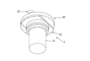
- the transfer robot 3 includes a base unit 31 incorporating a drive motor and the like, an arm unit 32 provided on the top of the base unit 31, and a robot flange member used for mounting the transfer robot 3. And 33.
- the transfer robot 3 according to the chamber structure of this embodiment is attached to the transfer chamber 1 by fixing the robot flange member 33 to the robot base member 20, and at the same time, the arm unit 32 of the transfer robot 3 is moved to the transfer chamber.
- 1 is a configuration that is arranged in the inside. Since the base unit 31 of the transfer robot 3 has a well-known configuration, detailed description thereof is omitted here.
- the arm unit 32 includes a pair of arms 41 and 42.
- Each of the arms 41 and 42 includes first arms 41a and 42a whose proximal end sides are fixed to the base unit 31, and second arms 41b and 42b attached to the distal end side of the first arm.
- An end effector (hand: not shown) for holding the work to be conveyed is attached to the distal end side of the second arms 41b and 42b. The end effector is detachable from the second arms 41b and 42b.
- the first arms 41a, 42a and the second arms 41b, 42b of both arms 41, 42 constituting the arm unit 32 are pivotably attached. Then, as shown in FIG. 7, both arms 41 and 42 are folded to a storage position suitable for attachment / detachment of the transfer robot 3 and transportation. Of course, when the workpiece is transferred by the transfer robot 3, the arms 41 and 42 can be extended / folded by controlling the first arms 41a and 42a and the second arms 41b and 42b to turn.
- the first arm 41a, 42a and the second arm 41b, 42b of each arm 41, 42 are overlapped in the up and down direction at the storage position, The one arm 41a, 42a is directed in the opposite direction back to back.
- the arms 41 and 42 are entirely within the inner method of the inner peripheral surface 21e.
- the arm unit 32 can be easily handled in maintenance work of the transfer chamber 1 and the transfer robot 3.
- the arms 41 and 42 positioned at the storage position can be fixed in a bent state by the fixing tool H.
- both arms 41 and 42 are fixed to the storage position by the fixing tool H, the handling property of the transfer robot 3 at the time of attachment / detachment / maintenance of the transfer robot 3 is improved.
- the arm unit 32 in which the arms 41 and 42 are positioned at the storage position is in a compactly folded state, and can be inserted into the opening hole 22a of the robot base member 20, as will be described later.
- the configuration of the arm unit 32 detailed descriptions of well-known configurations other than those described above are omitted.
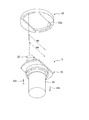
- the robot flange member 33 is detachably attached to the robot base member 20 when the transfer robot 3 is mounted on the transfer chamber 1. As shown in FIG. 7, the robot flange member 33 is disposed at a position above the base unit 31 of the transfer robot 3 and at a position below the arm unit 32.
- the robot flange member 33 includes an annular (or cylindrical) base body 33a and a flange part 33b extending in the radial direction from the upper end of the base body 33a (see FIGS. 5 and 6).
- the base body 33a includes an internal space (hollow part) surrounded by the inner peripheral surface 33c.
- the base body 33a is a part to which the base unit 31 of the transfer robot 3 is attached.
- the base main body 33a includes a mounting hole 33d used for mounting to the base unit 31 on the lower end surface thereof.
- the mounting hole 33d is more preferably arranged on the radially inner side of the inner peripheral surface 33c than a groove (sealing member mounting groove) 33g described later.
- the inner peripheral surface 33c of the base body 33a connects the arms 41, 42 and the base unit 31 to each other when the base unit 31, the robot flange member 33, and the arm unit 32 are assembled together to form the transfer robot 3.
- the transfer robot 3 installed in the transfer chamber 1 has the base unit 31, the arm unit 32, and the robot flange member 33 assembled together as shown in FIG. Is.
- the flange portion 33b of the robot flange portion 33 is attached to the robot base member 20 when the transfer robot 3 is installed in the transfer chamber 1.
- the outer shape of the flange portion 33b is a pair of arcs protruding outward and a pair of It has an oval shape surrounded by a straight line, and is substantially the same shape as the opening hole 22a of the robot base member 20. That is, when the robot flange member 33 is attached to the robot base member 20, the outer peripheral edge portion of the upper surface of the flange portion 33b comes into contact with the peripheral edge portion of the opening hole 22a on the lower surface of the robot base member 20, and the opening hole of the robot base member 20 22a is blocked by the robot flange member 33.
- the flange portion 33b includes an outer peripheral portion 33f including a plurality of attachment / detachment holes 33e used for attachment to the robot flange member 20, and a groove (seal member mounting groove) 33g disposed inside the attachment / detachment hole 33e.
- a sealing member such as an O-ring (not shown) is attached to the groove 33g.
- the transfer robot 3 attached to and detached from the chamber structure of the present embodiment is an assembly in which the base unit 31, the arm unit 32, and the robot flange member 33 of the transfer robot 3 are assembled together (see FIG. 7). .
- the transfer robot 3 in which the base unit 31, the arm unit 32, and the robot flange member 33 are integrally assembled is installed in the transfer chamber 1 as it is and only from the lower side. can do. That is, according to the chamber structure of the present embodiment, when the transfer robot 3 is installed in the transfer chamber 1, the base unit 31, the arm unit 32, and the robot flange member 33 are assembled together without being separated from each other. And can be attached from the lower side of the transfer chamber 1. Naturally, the arm unit 32 of the transfer robot 3 can be inserted through the opening 22a of the robot base member 20 while being integrally assembled.
- the robot flange member 33 is attached to the lower surface side of the robot base member 20, and the arm unit 32 is located in the transfer chamber 1.
- the base unit 31 is disposed on the lower side (outside) of the transfer chamber 1. Thereafter, the door 11a of the transfer chamber 1 is opened, and end effectors (not shown) are attached to the second arms 41b and 42b, respectively.
- end effectors (not shown) are attached to the second arms 41b and 42b, respectively.
- the robot flange member 33 attached to the robot base member 20 is removed from the robot base member 20 (flange removal step).
- the robot base member 20 is actually fixed to the lower surface of the transfer chamber 1.
- the mounting screw 33h (see FIG. 4) fixed to the robot base member 20 is removed from the lower side of the robot flange member 33.
- the entire transfer robot 3 together with the robot flange member 33 is moved below the robot base member 20 with the robot base member 20 fixed to the transfer chamber 1 side and removed. be able to.
- drawing of the transfer chamber 1 is also omitted.
- both the arms 41 and 42 of the arm unit 32 are located at the storage position, and are located in a range surrounded by the opening edge of the opening hole 22a, so that the opening hole 22a is left as it is. You can go through. Therefore, when the robot flange member 33 is moved downward, as shown in FIG. 9, the arm robot 32 in the transfer chamber 1 passes through the opening 22a in the transfer robot 3 at the mounting position. Thereafter, as shown in FIGS. 7 and 8, the transfer robot 3 is taken out (lower side) of the transfer chamber 1 (flange removal position).
- the transfer robot 3 when the transfer robot 3 is attached to the transfer chamber 1, it can be executed by performing the above-described steps in the reverse order.
- the transfer robot 3 can be attached to and detached from the transfer chamber 1 while the base unit 31 and the arm unit 32 remain integrated.
- the internal space of the transfer chamber 1 in which the arm unit 32 of the transfer robot 3 is installed is a narrow space, but the chamber structure of the present embodiment keeps the transfer robot 3 as it is, and The transfer chamber 1 can be installed / removed only from the lower side. For this reason, even if the internal space of the transfer chamber 1 is a narrow space, there is almost no influence on workability. That is, when the transfer robot 3 is installed or removed, there is no need to remove the arm unit 32 from the base unit 31 and remove only the arm unit 32 from the transfer chamber 1 in the transfer chamber 1.
- the opening 22a of the robot base member 20 is sized so that it can be inserted when the arm unit 32 of the transfer robot 3 is in the storage position.
- the entire transfer robot 3 can be taken out to the lower side (outside) of the transfer chamber 1 simply by removing the robot flange member 33 integrated with the transfer robot 3 from the robot base member 20 and moving it downward. That is, the transfer robot 3 can be attached to and detached from the transfer chamber 1 with good workability regardless of the size of the internal space of the transfer chamber 1.
- the chamber structure of the present embodiment has a transfer robot for the transfer chamber 1 only by accessing from the lower side of the transfer chamber 1 even if various devices are installed in the upper space of the transfer chamber 1. 3 can be installed / removed. Therefore, the chamber structure of the present embodiment can stably install / remove the transfer robot 3 with respect to the transfer chamber 1 without being influenced by the surrounding environment of the transfer chamber 1.
- the chamber structure according to the present invention can be applied to, for example, a chamber structure connected to a process apparatus such as ion implantation or etching in manufacturing a semiconductor substrate.
Landscapes
- Container, Conveyance, Adherence, Positioning, Of Wafer (AREA)
- Engineering & Computer Science (AREA)
- Manipulator (AREA)
- Drying Of Semiconductors (AREA)
- Physics & Mathematics (AREA)
- Plasma & Fusion (AREA)
- Robotics (AREA)
Abstract
搬送ロボットの設置や取り外しなどのメンテナンス作業性に優れたチャンバ構造を提供する。 搬送チャンバ1の搬送室11の底部13に設けた開口部にロボットベース部材20を介して搬送ロボット3を取り付けるチャンバ構造であって、前記開口部の下側にロボットベース部材20が設けられ、搬送ロボット3は、ベースユニット31と、該ベースユニット31の上部に設けられるアームユニット32とを有し、ベースユニット31の上側に、ロボットベース部材20の開口孔と同形状のロボットフランジ部材33が設けられ、前記アームユニット32は、前記開口孔に挿通自在であり、ロボットフランジ部材33は前記開口孔の周縁部に対して着脱自在に接続される。
Description
本発明は、搬送ロボットが設置される内部空間を備えるチャンバ構造に関し、特に、半導体基板などの基板製造におけるイオン注入やエッチング等のプロセス装置に接続されるチャンバ構造に関する。
半導体基板等の基板の製造プロセスでは、内部が真空に維持された搬送チャンバを経由して処理装置内で基板にイオン注入やエッチング等の処理が行われる。また、処理装置への基板等のワークの出し入れは、搬送チャンバに取り付けた搬送ロボットによって行われる。すなわち、搬送ロボットは、気密性が確保されており、高真空にすることが可能な、搬送チャンバの内部空間(搬送室)に設置されている。
搬送ロボットを搬送チャンバ内に新規設置する場合やメンテナンス等のために搬送チャンバ内の搬送ロボットを取り外す場合を考える。例えば、搬送チャンバ内の搬送ロボットを取り外す場合であれば、まず、搬送チャンバ内において搬送ロボットがベースユニットとベースユニットの上部に設けられるアームユニットとに上下に分割される。その後、分割された上側部分であるアームユニットが搬送チャンバの上側から取り出され、分割された下側部分であるベースユニットが搬送チャンバの下側から取り外される。
また、搬送チャンバ内に搬送ロボットを設置する場合は、上述した作業を逆の手順で行う必要がある。
また、搬送チャンバ内に搬送ロボットを設置する場合は、上述した作業を逆の手順で行う必要がある。
ところが、真空状態で使用される搬送チャンバ内は、所望の真空度に達するまでの時間をできる限り短くするために、搬送ロボットがギリギリに収まる程度の必要最小限の空間しかないことが一般的である。したがって、搬送ロボットが設置される搬送チャンバ内における搬送ロボット着脱時の作業は、作業者が無理のない姿勢で容易に行えるものではない。言い換えると、着脱時の作業、特に搬送ロボットの分割作業は、作業者の手がなかなか回り込まないような狭いスペースで行われるため、作業者に窮屈な姿勢を強いるものである。
また、従来の装置では、分割された搬送ロボットの上側のアームユニットをクレーンなどを用いて搬送チャンバの上方に確保した作業空間に取り出しており、このような作業を行う作業空間が搬送チャンバの上方に必要である(引用文献1の図2参照)。
ところが、搬送チャンバの上方空間は、製品の高品質化などの目的で各種の機器や装置を設置する空間として使用される傾向にあり、十分な上方空間を確保することが困難な状況にあり、作業性の更なる悪化を招いている。
このように、搬送ロボットを搬送チャンバに設置したり、取り外したりする作業性や、搬送ロボットのメンテナンスの作業性が徐々に悪化しているという問題があった。
ところが、搬送チャンバの上方空間は、製品の高品質化などの目的で各種の機器や装置を設置する空間として使用される傾向にあり、十分な上方空間を確保することが困難な状況にあり、作業性の更なる悪化を招いている。
このように、搬送ロボットを搬送チャンバに設置したり、取り外したりする作業性や、搬送ロボットのメンテナンスの作業性が徐々に悪化しているという問題があった。
本発明は、このような問題点に鑑みてなされたものであり、搬送ロボットが設置される搬送チャンバについて、搬送ロボットの設置や取り外しなどのメンテナンス作業性に優れたチャンバ構造を提供することを課題とする。
本発明は、搬送チャンバの内部空間である搬送室の底部に設けた開口部に、環状のロボットベース部材およびロボットフランジ部材を介して搬送ロボットを取り付けるチャンバ構造であって、前記搬送チャンバにおける前記開口部の下側に前記ロボットベース部材が設けられ、前記搬送ロボットは、ベースユニットと、該ベースユニットの上部に設けられるアームユニットとを有し、前記ベースユニットの上側に、前記ロボットベース部材の開口孔と同形状の前記ロボットフランジ部材が設けられ、前記アームユニットは、前記開口孔に挿通自在であるとともに、前記ロボットフランジ部材は前記開口孔の周縁部に対して着脱自在に接続される、ことを特徴とするチャンバ構造である。
前記ロボットフランジ部材は、前記アームユニットが前記搬送室内に設置されるフランジ装着位置から、前記アームユニットが前記開口孔を通り抜けて前記搬送室の外に取り出されたフランジ取外し位置に移動可能であると共に、当該フランジ取外し位置から前記開口孔を通り抜けて前記搬送室内に設置される前記フランジ装着位置に移動可能である。
前記ロボットベース部材は、前記搬送チャンバに取り付けられる外周部と、当該外周部の内側に形成された内周壁と、当該内周壁の内側に形成された前記開口孔とを備えており、前記内周壁の内周縁を上方に延長して画定される筒形空間は、前記搬送室内に設置された前記搬送ロボットの前記アームユニットの旋回エリアに対応している。
前記開口孔は、前記内周壁の内周縁内に配置されており、前記ロボットベース部材は、前記内周壁の内周縁と前記開口孔との間に、前記搬送室の底部を構成する底面部を備えている。
前記ロボットベース部材は、前記搬送チャンバへの取付けに用いられる取付孔を前記外周部に備えていると共に、前記ロボットフランジ部材の取付けに用いられる取付孔を前記底面部に備えている。
前記ロボットフランジ部材は、前記搬送ロボットの前記ベースユニットが取り付けられる環形状のベース本体と、当該ベース本体の上側に配置されるフランジ部とを備え、前記ベース本体は、前記搬送ロボットの前記アームユニットの、前記ベースユニットとの連結部が挿通される中空部を備え、前記フランジ部は、前記ロボットフランジ部材への取付けに用いられる複数の取付穴を備える外周部と、前記取付穴の内側に配置されたシール部材装着溝とを備えている。
前記ベース本体は、その下端面に、前記搬送ロボットの前記ベースユニットの取付けに用いられる取付孔を備えており、当該取付孔は、前記シール部材装着溝の内側に配置されている。
本発明に係るチャンバ構造は、搬送チャンバ内に搬送ロボットを設置したり搬送チャンバ内から搬送ロボットを取り外したりする際、搬送ロボットを上下に分割させることなくそのままの状態で、かつ、搬送チャンバの下側からのみのアクセスで、設置や取り外しを行うことができる。
1…搬送チャンバ、11…天井部11、11a…扉(天井蓋)、11b…一端側の接続部、
11c…他端側の接続部、12…側部、13…底部、13a…開口部、13b…下面、
20…ロボットベース部材、21…外周部(壁部)、21a…上端面、21b…取付孔、
21c…取付ネジ、21d…外周面、21e…内周面(内周縁)、
22…底面部、22a…開口孔、22c…取付ネジ、
3…搬送ロボット、31…ベースユニット、32…アームユニット、
33…ロボットフランジ部材、33a…ベース本体、33b…フランジ部、33c…内周面、
33d…取付孔、33e…着脱孔、33f…外周部、33g…溝(シール部材装着溝)、
33h…着脱ネジ、
41,42…一対のアーム、41a,42a…第1アーム、41b,42b…第2アーム、
H…固定具H、M…モジュール、S…筒形空間、
W1…アームユニットの最大寸法 、W2…内周面の内法寸法。
11c…他端側の接続部、12…側部、13…底部、13a…開口部、13b…下面、
20…ロボットベース部材、21…外周部(壁部)、21a…上端面、21b…取付孔、
21c…取付ネジ、21d…外周面、21e…内周面(内周縁)、
22…底面部、22a…開口孔、22c…取付ネジ、
3…搬送ロボット、31…ベースユニット、32…アームユニット、
33…ロボットフランジ部材、33a…ベース本体、33b…フランジ部、33c…内周面、
33d…取付孔、33e…着脱孔、33f…外周部、33g…溝(シール部材装着溝)、
33h…着脱ネジ、
41,42…一対のアーム、41a,42a…第1アーム、41b,42b…第2アーム、
H…固定具H、M…モジュール、S…筒形空間、
W1…アームユニットの最大寸法 、W2…内周面の内法寸法。
次に、本発明に係るチャンバ構造について、図面を参照しつつ説明する。
図1から図3に示されるように、搬送チャンバ1は、EFEM(Equipment Front End Module)などの半導体用のモジュールMに、一端側が接続された状態で設置されている。
なお、搬送チャンバ1の他端側(モジュールM側とは反対側)は、エッチング処理等を行うプロセス装置(不図示)やロードロックチャンバ等に接続される。
これらの構成については、周知であるので、ここでは、詳細な説明を省略する。
なお、搬送チャンバ1の他端側(モジュールM側とは反対側)は、エッチング処理等を行うプロセス装置(不図示)やロードロックチャンバ等に接続される。
これらの構成については、周知であるので、ここでは、詳細な説明を省略する。
搬送チャンバ1は、その内部に搬送ロボット3の一部が配置される空間を備え、天井部11、側部12及び底部13を備える矩形構造である。
天井部11は、搬送チャンバ1の上部開口に対してスライド開閉される天井蓋(扉)11aを備えているが、ここではその詳細な説明を省略する。
また、搬送チャンバ1は、モジュールMに接続される一端側11bにゲートバルブ(不図示)が設けられ、プロセス装置などに接続される他端側11cにもゲートバルブ(不図示)が設けられる。
これらの開閉可能な天井蓋11a及び両端側11b,11cのゲートバルブを閉じることで、搬送チャンバ1の内部空間は気密状態になり、真空ポンプにより搬送チャンバ1の内部空間の吸引を行うことで高真空状態となる。
なお、ゲートバルブや真空ポンプ等は周知技術であり、これらの構成については、ここでの説明及び図示を省略する。
天井部11は、搬送チャンバ1の上部開口に対してスライド開閉される天井蓋(扉)11aを備えているが、ここではその詳細な説明を省略する。
また、搬送チャンバ1は、モジュールMに接続される一端側11bにゲートバルブ(不図示)が設けられ、プロセス装置などに接続される他端側11cにもゲートバルブ(不図示)が設けられる。
これらの開閉可能な天井蓋11a及び両端側11b,11cのゲートバルブを閉じることで、搬送チャンバ1の内部空間は気密状態になり、真空ポンプにより搬送チャンバ1の内部空間の吸引を行うことで高真空状態となる。
なお、ゲートバルブや真空ポンプ等は周知技術であり、これらの構成については、ここでの説明及び図示を省略する。
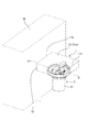
図4に示されるように、搬送チャンバ1は、その底部13に開口部13aを備えている。
そして、底部13にはロボットベース部材20が取り付けられている。より具体的には、ロボットベース部材20は、搬送チャンバ1の底部13の開口部13aの下側に、開口部13aを取り囲むように配置されており、底部13の下面13bに固定される。
搬送チャンバ1内に搬送ロボット3の後述のアームユニット32を設置する場合は、このロボットベース部材20に搬送ロボット3が固定される。具体的には、ロボットベース部材20には、搬送ロボット3が備える後述のロボットフランジ部材33が固定される。これにより、搬送ロボット3のアームユニット32のみが搬送チャンバ1の内部空間に収容される。搬送チャンバ1に設置される搬送ロボット3は、アームユニット32の最大旋回径が搬送チャンバ1の内部空間の内法以下に制限される。
そして、底部13にはロボットベース部材20が取り付けられている。より具体的には、ロボットベース部材20は、搬送チャンバ1の底部13の開口部13aの下側に、開口部13aを取り囲むように配置されており、底部13の下面13bに固定される。
搬送チャンバ1内に搬送ロボット3の後述のアームユニット32を設置する場合は、このロボットベース部材20に搬送ロボット3が固定される。具体的には、ロボットベース部材20には、搬送ロボット3が備える後述のロボットフランジ部材33が固定される。これにより、搬送ロボット3のアームユニット32のみが搬送チャンバ1の内部空間に収容される。搬送チャンバ1に設置される搬送ロボット3は、アームユニット32の最大旋回径が搬送チャンバ1の内部空間の内法以下に制限される。
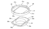
図5及び図6に示されるように、ロボットベース部材20は、搬送チャンバ1に取り付けられる環状の外周部21を備えている。ロボットベース部材20は環状(または円筒状)の部材ということができる。
外周部21は、環状の壁部で構成されており、外周部(壁部)21の上側には環状の上端面21aが形成されている。上端面21aは、ロボットベース部材20を搬送チャンバ1に固定する際、搬送チャンバ1の底部13の下面13bに当接される。
また、外周部21には、ロボットベース部材20を搬送チャンバ1に取り付ける際に用いられる複数の取付孔21bが形成されている。なお、取付けに用いられる取付ネジ21c(図4参照)については、周知の構成であるので詳細な説明を省略する。
外周部21は、環状の壁部で構成されており、外周部(壁部)21の上側には環状の上端面21aが形成されている。上端面21aは、ロボットベース部材20を搬送チャンバ1に固定する際、搬送チャンバ1の底部13の下面13bに当接される。
また、外周部21には、ロボットベース部材20を搬送チャンバ1に取り付ける際に用いられる複数の取付孔21bが形成されている。なお、取付けに用いられる取付ネジ21c(図4参照)については、周知の構成であるので詳細な説明を省略する。
ロボットベース部材20の外周部21は、その外側に形成された外周面21dと、内側に形成された内周面21eとを備えている。
内周面21eは、筒状に構成されている。そして、その内周面21eを内法とし、かつ、上方に延長して画定される筒形空間S(図7参照)は、ロボットベース部材20を搬送チャンバ(搬送室)1に設置したとき、搬送チャンバ1内に設置する収納ポジション(後述)におけるアームユニット32の最大寸法W1を規定する。なお、円筒形の内周面21eは、ロボットベース部材20を平面視したとき円形である。したがって、搬送チャンバ1内に設置する収納状態におけるアームユニット32は、その最大寸法W1が内周面21eの内法W2以下に制限される。
内周面21eは、筒状に構成されている。そして、その内周面21eを内法とし、かつ、上方に延長して画定される筒形空間S(図7参照)は、ロボットベース部材20を搬送チャンバ(搬送室)1に設置したとき、搬送チャンバ1内に設置する収納ポジション(後述)におけるアームユニット32の最大寸法W1を規定する。なお、円筒形の内周面21eは、ロボットベース部材20を平面視したとき円形である。したがって、搬送チャンバ1内に設置する収納状態におけるアームユニット32は、その最大寸法W1が内周面21eの内法W2以下に制限される。
ロボットベース部材20の底面部22は、ロボットベース部材20が搬送チャンバ1に固定された状態では、搬送チャンバ1の底部13の一部を構成する。そして、ロボットベース部材20の底面部22には、開口孔22aが形成されている。
開口孔22aは、本実施例では、外側に凸の一対の円弧と一対の直線によって囲まれた長円形状の開口である。この一対の円弧は、ロボットベース部材20の内周面21eとほぼ面一に形成される。
また、底面部22の下面における開口孔22aの周縁には、次に説明する搬送ロボット3のロボットフランジ部材33の取付けに用いられる取付孔21fが形成されている。なお、取付けに用いられる取付ネジ33h(図4参照)については、周知の構成であるので、詳細な説明を省略する。
開口孔22aは、本実施例では、外側に凸の一対の円弧と一対の直線によって囲まれた長円形状の開口である。この一対の円弧は、ロボットベース部材20の内周面21eとほぼ面一に形成される。
また、底面部22の下面における開口孔22aの周縁には、次に説明する搬送ロボット3のロボットフランジ部材33の取付けに用いられる取付孔21fが形成されている。なお、取付けに用いられる取付ネジ33h(図4参照)については、周知の構成であるので、詳細な説明を省略する。
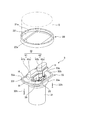
図7に示されるように、搬送ロボット3は、駆動用モータ等が内蔵されたベースユニット31と、ベースユニット31の上部に設けられるアームユニット32と、搬送ロボット3の取付けに用いられるロボットフランジ部材33とを備えている。
本実施例のチャンバ構造に係る搬送ロボット3は、後述するように、ロボットフランジ部材33をロボットベース部材20に固定することで搬送チャンバ1に取り付けられ、同時に搬送ロボット3のアームユニット32が搬送チャンバ1内に配置される構成である。なお、搬送ロボット3のベースユニット31は、周知の構成であるので、ここでは詳細な説明を省略する。
本実施例のチャンバ構造に係る搬送ロボット3は、後述するように、ロボットフランジ部材33をロボットベース部材20に固定することで搬送チャンバ1に取り付けられ、同時に搬送ロボット3のアームユニット32が搬送チャンバ1内に配置される構成である。なお、搬送ロボット3のベースユニット31は、周知の構成であるので、ここでは詳細な説明を省略する。
アームユニット32は、一対のアーム41,42を備えるものである。各アーム41,42は、基端側がベースユニット31に固定された第1アーム41a,42aと、第1アームの先端側に取り付けられた第2アーム41b,42bとを備えている。
なお、第2アーム41b,42bの先端側には、搬送するワークを保持するためのエンドイフェクタ(ハンド:不図示)が取り付けられる。エンドイフェクタは、第2アーム41b,42bに対して着脱自在である。
なお、第2アーム41b,42bの先端側には、搬送するワークを保持するためのエンドイフェクタ(ハンド:不図示)が取り付けられる。エンドイフェクタは、第2アーム41b,42bに対して着脱自在である。
アームユニット32を構成する両アーム41,42の第1アーム41a,42a及び第2アーム41b,42bは、旋回可能に取り付けられている。そして、両アーム41,42は、図7に示されるように、搬送ロボット3の取り付け/取り外し時や輸送時に適した収納ポジションに折り畳まれる。もちろん、搬送ロボット3によるワーク搬送時には、第1アーム41a,42a及び第2アーム41b,42bをそれぞれ旋回制御することで、両アーム41,42は伸長/折り畳みが可能である。
本実施形態のアームユニット32の場合、収納ポジションのとき、各アーム41,42の第1アーム41a,42aと第2アーム41b,42bは上下に重なった状態であり、両アーム41,42の第1アーム41a,42aは、背中合わせに逆方向に向けられる。両アーム41,42全体が、内周面21eの内法以下に収まっている。アームユニット32の両アーム41,42をこのようなポジションに位置させると、搬送チャンバ1や搬送ロボット3のメンテナンス作業等におけるアームユニット32の取り扱いが容易である。
なお、収納ポジションに位置された両アーム41,42は、固定具Hによって、その屈曲状態を固定することができる。両アーム41,42を固定具Hで収納ポジションに固定すると、搬送ロボット3の取り付け、取り外し、メンテナンスの際の搬送ロボット3の取扱性が向上する。
また、両アーム41,42が収納ポジションに位置されたアームユニット32は、コンパクトに折りたたまれた状態であり、後述するように、ロボットベース部材20の開口孔22aに挿通可能である。
なお、アームユニット32の構成のうち、上述した構成以外の周知の構成については詳細な説明を省略する。
本実施形態のアームユニット32の場合、収納ポジションのとき、各アーム41,42の第1アーム41a,42aと第2アーム41b,42bは上下に重なった状態であり、両アーム41,42の第1アーム41a,42aは、背中合わせに逆方向に向けられる。両アーム41,42全体が、内周面21eの内法以下に収まっている。アームユニット32の両アーム41,42をこのようなポジションに位置させると、搬送チャンバ1や搬送ロボット3のメンテナンス作業等におけるアームユニット32の取り扱いが容易である。
なお、収納ポジションに位置された両アーム41,42は、固定具Hによって、その屈曲状態を固定することができる。両アーム41,42を固定具Hで収納ポジションに固定すると、搬送ロボット3の取り付け、取り外し、メンテナンスの際の搬送ロボット3の取扱性が向上する。
また、両アーム41,42が収納ポジションに位置されたアームユニット32は、コンパクトに折りたたまれた状態であり、後述するように、ロボットベース部材20の開口孔22aに挿通可能である。
なお、アームユニット32の構成のうち、上述した構成以外の周知の構成については詳細な説明を省略する。
ロボットフランジ部材33は、搬送ロボット3を搬送チャンバ1に装着する際、ロボットベース部材20に着脱自在に取り付けられるものである。そして、図7に示されるように、ロボットフランジ部材33は、搬送ロボット3のベースユニット31の上側の位置であって、且つアームユニット32の下側の位置に配置されている。
そして、ロボットフランジ部材33は、環形状(または円筒状)のベース本体33aと、ベース本体33aの上端部から径方向延びるフランジ部33bとを備えている(図5及び図6参照)。ベース本体33aは、内周面33cに囲まれた内部空間(中空部)を備える。
そして、ロボットフランジ部材33は、環形状(または円筒状)のベース本体33aと、ベース本体33aの上端部から径方向延びるフランジ部33bとを備えている(図5及び図6参照)。ベース本体33aは、内周面33cに囲まれた内部空間(中空部)を備える。
ベース本体33aは、搬送ロボット3のベースユニット31が取り付けられる部位である。
そして、ベース本体33aは、その下端面に、ベースユニット31との取付けに用いられる取付孔33dを備えている。取付孔33dは、後述の溝(シール部材装着溝)33gよりも、内周面33cの径方向内側に配置されていることがより好ましい。なお、ベースユニット31の取付けに用いられる取付ネジ(不図示)については、周知の構成であるので、詳細な説明を省略する。
ベース本体33aの内周面33cは、ベースユニット31とロボットフランジ部材33とアームユニット32を一体に組み付けて搬送ロボット3とする際、両アーム41,42とベースユニット31とをそれぞれ連結させ、両アーム41,42を駆動させる駆動ユニット35,35が挿通される部位である。駆動ユニット35,35により、両アーム41,42は旋回動および昇降動される。
このように、本実施形態のチャンバ構造において、搬送チャンバ1に設置される搬送ロボット3は、図7に示されるように、ベースユニット31、アームユニット32及びロボットフランジ部材33が一体に組み付けられたものである。
そして、ベース本体33aは、その下端面に、ベースユニット31との取付けに用いられる取付孔33dを備えている。取付孔33dは、後述の溝(シール部材装着溝)33gよりも、内周面33cの径方向内側に配置されていることがより好ましい。なお、ベースユニット31の取付けに用いられる取付ネジ(不図示)については、周知の構成であるので、詳細な説明を省略する。
ベース本体33aの内周面33cは、ベースユニット31とロボットフランジ部材33とアームユニット32を一体に組み付けて搬送ロボット3とする際、両アーム41,42とベースユニット31とをそれぞれ連結させ、両アーム41,42を駆動させる駆動ユニット35,35が挿通される部位である。駆動ユニット35,35により、両アーム41,42は旋回動および昇降動される。
このように、本実施形態のチャンバ構造において、搬送チャンバ1に設置される搬送ロボット3は、図7に示されるように、ベースユニット31、アームユニット32及びロボットフランジ部材33が一体に組み付けられたものである。
ロボットフランジ部33のフランジ部33bは、搬送ロボット3を搬送チャンバ1に設置する際、ロボットベース部材20に取り付けられるものであり、フランジ部33bの外形は、外側に凸の一対の円弧と一対の直線によって囲まれた長円形状であり、ロボットベース部材20の開口孔22aとほぼ同形状である。
つまり、ロボットフランジ部材33をロボットベース部材20に取り付けるとき、フランジ部33bの上面の外周縁部がロボットベース部材20の下面の開口孔22aの周縁部に当接され、ロボットベース部材20の開口孔22aがロボットフランジ部材33で塞がれる。
つまり、ロボットフランジ部材33をロボットベース部材20に取り付けるとき、フランジ部33bの上面の外周縁部がロボットベース部材20の下面の開口孔22aの周縁部に当接され、ロボットベース部材20の開口孔22aがロボットフランジ部材33で塞がれる。
フランジ部33bは、ロボットフランジ部材20への取付けに用いられる複数の着脱穴33eを備える外周部33fと、着脱穴33eの内側に配置された溝(シール部材装着溝)33gとを備えている。この溝33gには、図示しないOリング等のシール部材が装着される。これにより、ロボットフランジ部材がロボットベース部材に対して着脱自在であっても、取り付け時のチャンバ内の気密性を確保することができる。
なお、ロボットフランジ部材33をロボットベース部材20に取り付けるための着脱ネジ33hについては、周知の構成であるので詳細な説明を省略する。
なお、ロボットフランジ部材33をロボットベース部材20に取り付けるための着脱ネジ33hについては、周知の構成であるので詳細な説明を省略する。
次に、本実施形態のチャンバ構造における、搬送ロボットの着脱手順について説明する。
まず、搬送ロボット3について説明する。
上述したように、本実施形態のチャンバ構造に着脱される搬送ロボット3は、搬送ロボット3のベースユニット31、アームユニット32及びロボットフランジ部材33が一体に組み付けられたものである(図7参照)。
本実施形態のチャンバ構造では、ベースユニット31、アームユニット32及びロボットフランジ部材33が一体に組み付けられた搬送ロボット3を、そのままの状態で、かつ、下側からのアクセスのみで搬送チャンバ1に設置することができる。つまり、本実施形態のチャンバ構造によれば、搬送ロボット3を搬送チャンバ1内に設置する際、ベースユニット31、アームユニット32及びロボットフランジ部材33をそれぞれに分離させることなく、一体に組み付けた状態のまま、かつ、搬送チャンバ1の下側から取り付けることができる。当然、搬送ロボット3のアームユニット32は、一体に組み付けられた状態のまま、ロボットベース部材20の開口孔22aを挿通させることができる。
上述したように、本実施形態のチャンバ構造に着脱される搬送ロボット3は、搬送ロボット3のベースユニット31、アームユニット32及びロボットフランジ部材33が一体に組み付けられたものである(図7参照)。
本実施形態のチャンバ構造では、ベースユニット31、アームユニット32及びロボットフランジ部材33が一体に組み付けられた搬送ロボット3を、そのままの状態で、かつ、下側からのアクセスのみで搬送チャンバ1に設置することができる。つまり、本実施形態のチャンバ構造によれば、搬送ロボット3を搬送チャンバ1内に設置する際、ベースユニット31、アームユニット32及びロボットフランジ部材33をそれぞれに分離させることなく、一体に組み付けた状態のまま、かつ、搬送チャンバ1の下側から取り付けることができる。当然、搬送ロボット3のアームユニット32は、一体に組み付けられた状態のまま、ロボットベース部材20の開口孔22aを挿通させることができる。
そして、図1及び図2に示されるように、搬送チャンバ1に搬送ロボット3を設置することで、ロボットフランジ部材33がロボットベース部材20の下面側に取り付けられ、アームユニット32が搬送チャンバ1内に収容され、ベースユニット31が搬送チャンバ1の下側(外側)に配置される。その後、搬送チャンバ1の扉11aを開け、第2アーム41b,42bにエンドイフェクタ(不図示)がそれぞれ取り付けられる。
以下、このように搬送チャンバ1に設置された搬送ロボット3を、搬送チャンバ1から取り外す手順を例に挙げて説明する。
以下、このように搬送チャンバ1に設置された搬送ロボット3を、搬送チャンバ1から取り外す手順を例に挙げて説明する。
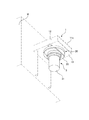
先ず、図3および図10に示す接続状態の搬送チャンバ1と搬送ロボット3とにおいて、ロボットベース部材20に取り付けられたロボットフランジ部材33を、ロボットベース部材20から取り外す(フランジ取り外し工程)。なお、図10においては、搬送チャンバ1の描画を省略しているが、実際には、ロボットベース部材20は搬送チャンバ1の下面に固定されている。
具体的には、まず、ロボットフランジ部材33の下側からロボットベース部材20に固定された取付ネジ33h(図4参照)を取り外す。これにより、図8および図9に示すように、ロボットベース部材20を搬送チャンバ1側に固定した状態のままロボットフランジ部材33とともに搬送ロボット3の全体をロボットベース部材20の下方に移動させ、取り外すことができる。なお、図8および図9においても、搬送チャンバ1の描画を省略している。
上述したように、アームユニット32の両アーム41,42は、収納ポジションに位置されており、開口孔22aの開口縁で囲まれる範囲に位置していることから、開口孔22aをそのままの状態で通り抜けることができる。
したがって、ロボットフランジ部材33を下方に移動させると、装着位置の搬送ロボット3は、図9に示すように、搬送チャンバ1内のアームユニット32が開口孔22aを通り抜ける。その後、図7および図8に示すように、搬送ロボット3は、搬送チャンバ1の外側(下側)に取り出される(フランジ取り外し位置)。
具体的には、まず、ロボットフランジ部材33の下側からロボットベース部材20に固定された取付ネジ33h(図4参照)を取り外す。これにより、図8および図9に示すように、ロボットベース部材20を搬送チャンバ1側に固定した状態のままロボットフランジ部材33とともに搬送ロボット3の全体をロボットベース部材20の下方に移動させ、取り外すことができる。なお、図8および図9においても、搬送チャンバ1の描画を省略している。
上述したように、アームユニット32の両アーム41,42は、収納ポジションに位置されており、開口孔22aの開口縁で囲まれる範囲に位置していることから、開口孔22aをそのままの状態で通り抜けることができる。
したがって、ロボットフランジ部材33を下方に移動させると、装着位置の搬送ロボット3は、図9に示すように、搬送チャンバ1内のアームユニット32が開口孔22aを通り抜ける。その後、図7および図8に示すように、搬送ロボット3は、搬送チャンバ1の外側(下側)に取り出される(フランジ取り外し位置)。
また、搬送ロボット3を搬送チャンバ1に取り付ける場合は、上述した工程を逆の順番で行うことによって実行することができる。
このように、本実施形態のチャンバ構造によれば、ベースユニット31とアームユニット32が一体のままで搬送ロボット3を搬送チャンバ1に対して着脱することができる。
上述したように、搬送ロボット3のアームユニット32が設置される搬送チャンバ1の内部空間は、狭小な空間であるが、本実施形態のチャンバ構造は、搬送ロボット3をそのままの状態で、かつ、下側からのアクセスのみで搬送チャンバ1に対する設置/取り外しができる。このため、搬送チャンバ1の内部空間が狭小空間であっても、作業性に及ぼす影響はほとんど無い。つまり、搬送ロボット3の設置や取り外しの際に、搬送チャンバ1内においてアームユニット32をベースユニット31から取り外し、アームユニット32だけを搬送チャンバ1から取り出す作業を行う必要がない。
また、本実施形態のチャンバ構造は、ロボットベース部材20の開口孔22aを、搬送ロボット3のアームユニット32が収納ポジションにあるときに挿通可能な大きさとしている。このため、搬送ロボット3に一体化されたロボットフランジ部材33をロボットベース部材20から取り外して下方に移動させるだけで、搬送ロボット3全体を搬送チャンバ1の下側(外側)に取り出すことができる。すなわち、搬送チャンバ1の内部空間の大きさに関係なく、搬送ロボット3を良好な作業性で搬送チャンバ1に対して着脱することができる。
また、本実施形態のチャンバ構造は、ロボットベース部材20の開口孔22aを、搬送ロボット3のアームユニット32が収納ポジションにあるときに挿通可能な大きさとしている。このため、搬送ロボット3に一体化されたロボットフランジ部材33をロボットベース部材20から取り外して下方に移動させるだけで、搬送ロボット3全体を搬送チャンバ1の下側(外側)に取り出すことができる。すなわち、搬送チャンバ1の内部空間の大きさに関係なく、搬送ロボット3を良好な作業性で搬送チャンバ1に対して着脱することができる。
また、本実施形態のチャンバ構造は、仮に搬送チャンバ1の上側の空間に種々の装置が設置されている場合であっても、搬送チャンバ1の下側からのアクセスのみで搬送チャンバ1に対する搬送ロボット3の設置/取り外しを行うことができる。よって、本実施形態のチャンバ構造は、搬送チャンバ1の周囲環境に左右されることなく、搬送チャンバ1に対する搬送ロボット3の設置/取り外しを安定的に行うことが可能である。
本発明に係るチャンバ構造は、例えば、半導体基板製造におけるイオン注入やエッチング等のプロセス装置に接続されるチャンバ構造に適用することができる。
Claims (7)
- 搬送チャンバの内部空間である搬送室の底部に設けた開口部に、環状のロボットベース部材およびロボットフランジ部材を介して搬送ロボットを取り付けるチャンバ構造であって、
前記搬送チャンバにおける前記開口部の下側に前記ロボットベース部材が設けられ、
前記搬送ロボットは、ベースユニットと、該ベースユニットの上部に設けられるアームユニットとを有し、
前記ベースユニットの上側に、前記ロボットベース部材の開口孔と同形状の前記ロボットフランジ部材が設けられ、
前記アームユニットは、前記開口孔に挿通自在であるとともに、前記ロボットフランジ部材は前記開口孔の周縁部に対して着脱自在に接続される、
ことを特徴とするチャンバ構造。 - 前記ロボットフランジ部材は、前記アームユニットが前記搬送室内に設置されるフランジ装着位置から、前記アームユニットが前記開口孔を通り抜けて前記搬送室の外に取り出されたフランジ取外し位置に移動可能であると共に、当該フランジ取外し位置から前記開口孔を通り抜けて前記搬送室内に設置される前記フランジ装着位置に移動可能である、
請求項1に記載のチャンバ構造。 - 前記ロボットベース部材は、前記搬送チャンバに取り付けられる外周部と、当該外周部の内側に形成された内周壁と、当該内周壁の内側に形成された前記開口孔とを備えており、
前記内周壁の内周縁を上方に延長して画定される筒形空間は、前記搬送室内に設置された前記搬送ロボットの前記アームユニットの旋回エリアに対応している、
請求項1又は請求項2に記載のチャンバ構造。 - 前記開口孔は、前記内周壁の内周縁内に配置されており、
前記ロボットベース部材は、前記内周壁の内周縁と前記開口孔との間に、前記搬送室の底部を構成する底面部を備えている、
請求項3に記載のチャンバ構造。 - 前記ロボットベース部材は、前記搬送チャンバへの取付けに用いられる取付孔を前記外周部に備えていると共に、前記ロボットフランジ部材の取付けに用いられる取付孔を前記底面部に備えている、請求項3又は請求項4に記載のチャンバ構造。
- 前記ロボットフランジ部材は、前記搬送ロボットの前記ベースユニットが取り付けられる環形状のベース本体と、当該ベース本体の上側に配置されるフランジ部とを備え、
前記ベース本体は、前記搬送ロボットの前記アームユニットの、前記ベースユニットとの連結部が挿通される中空部を備え、
前記フランジ部は、前記ロボットフランジ部材への取付けに用いられる複数の取付穴を備える外周部と、前記取付穴の内側に配置されたシール部材装着溝とを備えている、請求項1から請求項5のいずれか一項に記載のチャンバ構造。 - 前記ベース本体は、その下端面に、前記搬送ロボットの前記ベースユニットの取付けに用いられる取付孔を備えており、
当該取付孔は、前記シール部材装着溝の内側に配置されている、
請求項6に記載のチャンバ構造。
Priority Applications (3)
| Application Number | Priority Date | Filing Date | Title |
|---|---|---|---|
| US17/043,490 US11387128B2 (en) | 2018-03-31 | 2019-03-29 | Chamber structure |
| JP2020509356A JP6945059B2 (ja) | 2018-03-31 | 2019-03-29 | チャンバ構造 |
| CN201980023951.1A CN111971784B (zh) | 2018-03-31 | 2019-03-29 | 腔室构造 |
Applications Claiming Priority (2)
| Application Number | Priority Date | Filing Date | Title |
|---|---|---|---|
| JP2018-070476 | 2018-03-31 | ||
| JP2018070476 | 2018-03-31 |
Publications (1)
| Publication Number | Publication Date |
|---|---|
| WO2019189883A1 true WO2019189883A1 (ja) | 2019-10-03 |
Family
ID=68060257
Family Applications (1)
| Application Number | Title | Priority Date | Filing Date |
|---|---|---|---|
| PCT/JP2019/014336 Ceased WO2019189883A1 (ja) | 2018-03-31 | 2019-03-29 | チャンバ構造 |
Country Status (5)
| Country | Link |
|---|---|
| US (1) | US11387128B2 (ja) |
| JP (1) | JP6945059B2 (ja) |
| CN (1) | CN111971784B (ja) |
| TW (1) | TWI758595B (ja) |
| WO (1) | WO2019189883A1 (ja) |
Cited By (2)
| Publication number | Priority date | Publication date | Assignee | Title |
|---|---|---|---|---|
| WO2024171806A1 (ja) * | 2023-02-13 | 2024-08-22 | 東京エレクトロン株式会社 | 基板処理システム及び台車 |
| US12533794B2 (en) | 2023-07-06 | 2026-01-27 | Kabushiki Kaisha Yaskawa Denki | Robot with two-axis hand motor |
Families Citing this family (3)
| Publication number | Priority date | Publication date | Assignee | Title |
|---|---|---|---|---|
| CN115547882B (zh) * | 2022-06-27 | 2026-01-23 | 北京北方华创微电子装备有限公司 | 传输腔室及半导体工艺设备 |
| TW202539833A (zh) * | 2023-09-28 | 2025-10-16 | 荷蘭商Asm Ip私人控股有限公司 | 基板搬運腔室前驅體及製造基板搬運腔室之方法 |
| CN117352434A (zh) * | 2023-10-27 | 2024-01-05 | 北京北方华创微电子装备有限公司 | 一种传输腔室、半导体工艺设备及拆装工装 |
Citations (8)
| Publication number | Priority date | Publication date | Assignee | Title |
|---|---|---|---|---|
| JPH11117067A (ja) * | 1997-10-09 | 1999-04-27 | Nissin Electric Co Ltd | 被処理物品ハンドリング装置 |
| JPH11198070A (ja) * | 1998-01-12 | 1999-07-27 | Shin Meiwa Ind Co Ltd | 搬送装置 |
| JPH11354603A (ja) * | 1998-06-05 | 1999-12-24 | Hitachi Ltd | 搬送装置およびそれを用いた半導体製造装置 |
| JP2000216218A (ja) * | 1999-01-27 | 2000-08-04 | Dainippon Screen Mfg Co Ltd | 基板搬送装置および基板処理装置 |
| JP2000260850A (ja) * | 1999-03-09 | 2000-09-22 | Sumitomo Heavy Ind Ltd | 真空ロボットの取付装置 |
| JP2001035902A (ja) * | 1999-07-26 | 2001-02-09 | Jel:Kk | 基板搬送用ロボット |
| JP2012195336A (ja) * | 2011-03-15 | 2012-10-11 | Ulvac Japan Ltd | 回転駆動装置 |
| JP2013126707A (ja) * | 2011-12-19 | 2013-06-27 | Yaskawa Electric Corp | ロボットおよびロボットの設置方法 |
Family Cites Families (19)
| Publication number | Priority date | Publication date | Assignee | Title |
|---|---|---|---|---|
| US4735548A (en) * | 1987-04-20 | 1988-04-05 | Mecs Corporation | Carrier system for clean room |
| JP3638735B2 (ja) * | 1996-11-12 | 2005-04-13 | 大日本スクリーン製造株式会社 | 基板処理装置 |
| US6126381A (en) * | 1997-04-01 | 2000-10-03 | Kensington Laboratories, Inc. | Unitary specimen prealigner and continuously rotatable four link robot arm mechanism |
| US6485250B2 (en) * | 1998-12-30 | 2002-11-26 | Brooks Automation Inc. | Substrate transport apparatus with multiple arms on a common axis of rotation |
| US6242879B1 (en) * | 2000-03-13 | 2001-06-05 | Berkeley Process Control, Inc. | Touch calibration system for wafer transfer robot |
| JP3971601B2 (ja) * | 2000-11-28 | 2007-09-05 | 大日本スクリーン製造株式会社 | 基板受渡装置および基板処理装置 |
| JP2003100695A (ja) * | 2001-09-26 | 2003-04-04 | Dainippon Screen Mfg Co Ltd | 基板洗浄装置 |
| JP4197103B2 (ja) | 2002-04-15 | 2008-12-17 | 株式会社荏原製作所 | ポリッシング装置 |
| JP4291709B2 (ja) * | 2003-04-16 | 2009-07-08 | 株式会社ダイヘン | 直線移動機構およびこれを用いた搬送ロボット |
| JP2006086234A (ja) * | 2004-09-14 | 2006-03-30 | Hitachi Kokusai Electric Inc | 基板処理装置 |
| JP2008135630A (ja) * | 2006-11-29 | 2008-06-12 | Jel:Kk | 基板搬送装置 |
| JP4903728B2 (ja) | 2008-01-11 | 2012-03-28 | 株式会社アルバック | 搬送ロボットが装置された搬送室及びそのメンテナンス方法。 |
| US9312153B2 (en) * | 2010-08-06 | 2016-04-12 | Tokyo Electron Limited | Substrate processing system, transfer module, substrate processing method, and method for manufacturing semiconductor element |
| TWI586500B (zh) * | 2010-10-08 | 2017-06-11 | 布魯克斯自動機械公司 | 機器人運送裝置及基板處理裝置 |
| JP6525499B2 (ja) | 2010-10-08 | 2019-06-05 | ブルックス オートメーション インコーポレイテッド | 同軸駆動真空ロボット |
| JP5403021B2 (ja) * | 2011-09-08 | 2014-01-29 | 株式会社安川電機 | ロボット、ロボットの設置方法および製造装置 |
| JP5990359B2 (ja) * | 2012-10-04 | 2016-09-14 | 平田機工株式会社 | 搬入出ロボット |
| JP6594177B2 (ja) * | 2015-11-24 | 2019-10-23 | 平田機工株式会社 | ハンド部材およびハンド |
| JP6618876B2 (ja) * | 2016-09-26 | 2019-12-11 | 株式会社ニューフレアテクノロジー | 基板処理装置、搬送方法およびサセプタ |
-
2019
- 2019-03-28 TW TW108110855A patent/TWI758595B/zh active
- 2019-03-29 WO PCT/JP2019/014336 patent/WO2019189883A1/ja not_active Ceased
- 2019-03-29 US US17/043,490 patent/US11387128B2/en active Active
- 2019-03-29 JP JP2020509356A patent/JP6945059B2/ja active Active
- 2019-03-29 CN CN201980023951.1A patent/CN111971784B/zh active Active
Patent Citations (8)
| Publication number | Priority date | Publication date | Assignee | Title |
|---|---|---|---|---|
| JPH11117067A (ja) * | 1997-10-09 | 1999-04-27 | Nissin Electric Co Ltd | 被処理物品ハンドリング装置 |
| JPH11198070A (ja) * | 1998-01-12 | 1999-07-27 | Shin Meiwa Ind Co Ltd | 搬送装置 |
| JPH11354603A (ja) * | 1998-06-05 | 1999-12-24 | Hitachi Ltd | 搬送装置およびそれを用いた半導体製造装置 |
| JP2000216218A (ja) * | 1999-01-27 | 2000-08-04 | Dainippon Screen Mfg Co Ltd | 基板搬送装置および基板処理装置 |
| JP2000260850A (ja) * | 1999-03-09 | 2000-09-22 | Sumitomo Heavy Ind Ltd | 真空ロボットの取付装置 |
| JP2001035902A (ja) * | 1999-07-26 | 2001-02-09 | Jel:Kk | 基板搬送用ロボット |
| JP2012195336A (ja) * | 2011-03-15 | 2012-10-11 | Ulvac Japan Ltd | 回転駆動装置 |
| JP2013126707A (ja) * | 2011-12-19 | 2013-06-27 | Yaskawa Electric Corp | ロボットおよびロボットの設置方法 |
Cited By (2)
| Publication number | Priority date | Publication date | Assignee | Title |
|---|---|---|---|---|
| WO2024171806A1 (ja) * | 2023-02-13 | 2024-08-22 | 東京エレクトロン株式会社 | 基板処理システム及び台車 |
| US12533794B2 (en) | 2023-07-06 | 2026-01-27 | Kabushiki Kaisha Yaskawa Denki | Robot with two-axis hand motor |
Also Published As
| Publication number | Publication date |
|---|---|
| US11387128B2 (en) | 2022-07-12 |
| CN111971784B (zh) | 2023-07-04 |
| US20210111051A1 (en) | 2021-04-15 |
| TWI758595B (zh) | 2022-03-21 |
| CN111971784A (zh) | 2020-11-20 |
| JP6945059B2 (ja) | 2021-10-06 |
| JPWO2019189883A1 (ja) | 2021-04-30 |
| TW201943006A (zh) | 2019-11-01 |
Similar Documents
| Publication | Publication Date | Title |
|---|---|---|
| JP6945059B2 (ja) | チャンバ構造 | |
| CN210778476U (zh) | 用于半导体处理模块的顶环 | |
| US20160240410A1 (en) | Substrate lift assemblies | |
| US20040237244A1 (en) | Purge system for product container and interface seal used in the system | |
| JP2019533313A (ja) | 可撓性機器フロントエンドモジュールインターフェース、環境制御された機器フロントエンドモジュール、及び組み付け方法 | |
| US10278501B2 (en) | Load lock door assembly, load lock apparatus, electronic device processing systems, and methods | |
| KR19980080903A (ko) | 유지보수동안 진공을 보존하는 격리밸브를 가진 챔버 | |
| US9145611B2 (en) | Load lock chamber with slit valve doors | |
| TWI693657B (zh) | 治具及組裝晶圓盤的方法 | |
| JP2015532001A (ja) | 異なるサイズのワークを取り扱う装置及び方法 | |
| TW201618223A (zh) | 基板傳送設備 | |
| US7431813B2 (en) | Multi-chambered substrate processing equipment having sealing structure between chambers thereof, and method of assembling such equipment | |
| US20160075012A1 (en) | Multi-component robotic hub mounting plate to facilitate hub removal | |
| KR102852934B1 (ko) | 회전 가능한 상단 플레이트 어셈블리를 갖는 멀티-스테이션 툴 | |
| CN115066744B (zh) | 机器人以及包括机器人的基板运送系统 | |
| KR102098568B1 (ko) | 제거가능한 격리 밸브 쉴드 인서트 조립체 | |
| JP2019062104A (ja) | ロードポート装置、ロードポート装置の駆動方法 | |
| JP6352012B2 (ja) | プラズマ処理装置 | |
| KR100187372B1 (ko) | 멀티챔버형 반도체소자 제조설비 | |
| JP2024046126A (ja) | プラズマ処理装置 | |
| TW202518631A (zh) | 蓋移動系統、封閉體、及使蓋移動之方法 | |
| JP3884626B2 (ja) | 基板処理装置およびそのメンテナンス方法 | |
| JP2004036760A (ja) | 真空用ゲート弁 | |
| WO2002055392A2 (en) | Apparatus and method for transporting a container | |
| KR20070031674A (ko) | 웨이퍼 이송 모니터링 유닛을 구비한 트랜스퍼 챔버 |
Legal Events
| Date | Code | Title | Description |
|---|---|---|---|
| 121 | Ep: the epo has been informed by wipo that ep was designated in this application |
Ref document number: 19776657 Country of ref document: EP Kind code of ref document: A1 |
|
| ENP | Entry into the national phase |
Ref document number: 2020509356 Country of ref document: JP Kind code of ref document: A |
|
| 122 | Ep: pct application non-entry in european phase |
Ref document number: 19776657 Country of ref document: EP Kind code of ref document: A1 |