WO2019189430A1 - 建設機械 - Google Patents
建設機械 Download PDFInfo
- Publication number
- WO2019189430A1 WO2019189430A1 PCT/JP2019/013304 JP2019013304W WO2019189430A1 WO 2019189430 A1 WO2019189430 A1 WO 2019189430A1 JP 2019013304 W JP2019013304 W JP 2019013304W WO 2019189430 A1 WO2019189430 A1 WO 2019189430A1
- Authority
- WO
- WIPO (PCT)
- Prior art keywords
- attachment
- construction machine
- surrounding
- information
- image
- Prior art date
Links
- 238000010276 construction Methods 0.000 title claims abstract description 95
- 238000001514 detection method Methods 0.000 claims description 73
- 230000005540 biological transmission Effects 0.000 claims description 20
- 238000004891 communication Methods 0.000 claims description 12
- 241000030361 Girellinae Species 0.000 description 17
- 238000013459 approach Methods 0.000 description 16
- 238000010586 diagram Methods 0.000 description 14
- 230000002093 peripheral effect Effects 0.000 description 9
- 238000012545 processing Methods 0.000 description 7
- 238000000034 method Methods 0.000 description 5
- 230000000694 effects Effects 0.000 description 4
- 239000003550 marker Substances 0.000 description 4
- 230000000007 visual effect Effects 0.000 description 4
- 239000003086 colorant Substances 0.000 description 3
- 238000012905 input function Methods 0.000 description 2
- 239000004973 liquid crystal related substance Substances 0.000 description 2
- 241001482107 Alosa sapidissima Species 0.000 description 1
- 230000003190 augmentative effect Effects 0.000 description 1
- 238000004364 calculation method Methods 0.000 description 1
- 238000013461 design Methods 0.000 description 1
Images


Classifications
-
- E—FIXED CONSTRUCTIONS
- E02—HYDRAULIC ENGINEERING; FOUNDATIONS; SOIL SHIFTING
- E02F—DREDGING; SOIL-SHIFTING
- E02F9/00—Component parts of dredgers or soil-shifting machines, not restricted to one of the kinds covered by groups E02F3/00 - E02F7/00
- E02F9/26—Indicating devices
- E02F9/261—Surveying the work-site to be treated
- E02F9/262—Surveying the work-site to be treated with follow-up actions to control the work tool, e.g. controller
-
- E—FIXED CONSTRUCTIONS
- E02—HYDRAULIC ENGINEERING; FOUNDATIONS; SOIL SHIFTING
- E02F—DREDGING; SOIL-SHIFTING
- E02F9/00—Component parts of dredgers or soil-shifting machines, not restricted to one of the kinds covered by groups E02F3/00 - E02F7/00
- E02F9/26—Indicating devices
- E02F9/261—Surveying the work-site to be treated
-
- G—PHYSICS
- G02—OPTICS
- G02B—OPTICAL ELEMENTS, SYSTEMS OR APPARATUS
- G02B27/00—Optical systems or apparatus not provided for by any of the groups G02B1/00 - G02B26/00, G02B30/00
- G02B27/01—Head-up displays
- G02B27/017—Head mounted
- G02B27/0172—Head mounted characterised by optical features
-
- E—FIXED CONSTRUCTIONS
- E02—HYDRAULIC ENGINEERING; FOUNDATIONS; SOIL SHIFTING
- E02F—DREDGING; SOIL-SHIFTING
- E02F9/00—Component parts of dredgers or soil-shifting machines, not restricted to one of the kinds covered by groups E02F3/00 - E02F7/00
- E02F9/20—Drives; Control devices
- E02F9/2025—Particular purposes of control systems not otherwise provided for
- E02F9/205—Remotely operated machines, e.g. unmanned vehicles
-
- G—PHYSICS
- G02—OPTICS
- G02B—OPTICAL ELEMENTS, SYSTEMS OR APPARATUS
- G02B27/00—Optical systems or apparatus not provided for by any of the groups G02B1/00 - G02B26/00, G02B30/00
- G02B27/01—Head-up displays
- G02B27/0101—Head-up displays characterised by optical features
- G02B2027/014—Head-up displays characterised by optical features comprising information/image processing systems
-
- G—PHYSICS
- G02—OPTICS
- G02B—OPTICAL ELEMENTS, SYSTEMS OR APPARATUS
- G02B27/00—Optical systems or apparatus not provided for by any of the groups G02B1/00 - G02B26/00, G02B30/00
- G02B27/01—Head-up displays
- G02B27/0101—Head-up displays characterised by optical features
- G02B2027/0141—Head-up displays characterised by optical features characterised by the informative content of the display
-
- G—PHYSICS
- G02—OPTICS
- G02B—OPTICAL ELEMENTS, SYSTEMS OR APPARATUS
- G02B27/00—Optical systems or apparatus not provided for by any of the groups G02B1/00 - G02B26/00, G02B30/00
- G02B27/01—Head-up displays
- G02B27/017—Head mounted
- G02B2027/0178—Eyeglass type
-
- H—ELECTRICITY
- H04—ELECTRIC COMMUNICATION TECHNIQUE
- H04N—PICTORIAL COMMUNICATION, e.g. TELEVISION
- H04N7/00—Television systems
- H04N7/18—Closed-circuit television [CCTV] systems, i.e. systems in which the video signal is not broadcast
- H04N7/183—Closed-circuit television [CCTV] systems, i.e. systems in which the video signal is not broadcast for receiving images from a single remote source
Definitions
- the present invention relates to a construction machine.
- Patent Document 1 There is known a technique for displaying distance information between a plane (reference position) on which a construction machine is located and the tip of an attachment as a number, together with the attachment, on a display device mounted in a cab of the construction machine (for example, Patent Document 1). reference).
- Patent Document 2 discloses a technique for displaying the necessary information on the display device by superimposing the necessary information as a character display or a color display on the side of the tip attachment.
- Patent Document 1 since distance information is displayed only with numbers, it is difficult for an operator to intuitively grasp the work situation, and in a surrounding work area (site) with unevenness and a slope. There is a problem that it is difficult to cope with work.
- Patent Document 2 only provides information necessary for the operation to be superimposed on the side of the tip attachment as a character display or a display including a color. Guidance function is not enough.
- An object of the present invention is to provide a construction machine having a guidance function that makes it easy for an operator to approach an attachment to a target position in a surrounding work area (target work site).
- a construction machine having an attachment including a tip attachment, an attachment state detection device for detecting the state of the attachment, and an attachment state based on the state of the attachment detected by the attachment state detection device
- Attachment position information generating unit for generating attachment position information, which is information about the position, display device, information on the attachment position information generated by the attachment position information generating unit, and information on the three-dimensional shape of the work area surrounding the construction machine
- a display control unit that controls the display device to display attachment related information generated based on the three-dimensional shape information.
- the attachment related information is set on the basis of a projection direction or a predetermined condition in which an ambient image that is an image corresponding to the three-dimensional shape of the surrounding work area and an image corresponding to the tip attachment are arbitrarily set. This is information corresponding to an image obtained by superimposing a projection image projected on the surrounding image in the projection direction.
- FIG. 1 is a side view showing a schematic configuration of a hydraulic excavator as a construction machine according to Embodiment 1 of the present invention. It is explanatory drawing for demonstrating the direction which projects the attachment of the hydraulic shovel shown in FIG. It is a block diagram which shows the main functions of the hydraulic shovel shown in FIG. It is a flowchart which shows the flow of the control processing which superimposes and displays the projection image of a tip attachment (bucket) on a surrounding image. It is a figure which shows the example which expressed the projection image of the bucket as a front-end
- FIG. 1 It is a figure which shows the example which expressed the projection image of the nibra as a tip attachment with the color shading in the screen of the display apparatus in the nibbler heavy machine as a construction machine concerning Embodiment 2 of this invention. It is explanatory drawing which expanded the A section in FIG. It is a block diagram which shows the main functions of the nibler heavy machine shown in FIG. It is a flowchart which shows the flow of the control processing which superimposes and displays the projection image of a tip attachment (nibra) on a surrounding image. It is a side view which shows schematic structure of the hydraulic shovel as a construction machine concerning Embodiment 3 of this invention. It is a block diagram which shows the main functions of the hydraulic shovel shown in FIG.
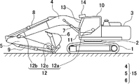
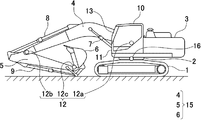
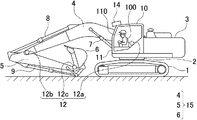
- FIG. 1 is a side view showing a schematic configuration of a hydraulic excavator as a construction machine according to Embodiment 1 of the present invention.
- FIG. 2 is an explanatory diagram for explaining a direction in which the attachment 15 of the excavator shown in FIG. 1 is projected.
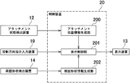
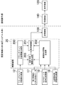
- FIG. 3 is a block diagram showing the main functions of the hydraulic excavator shown in FIG.
- FIG. 4 is a flowchart showing a flow of control processing for superimposing and displaying the projection image of the bucket 6 as the tip attachment of the attachment 15 shown in FIG. 1 on the surrounding image.
- FIG. 5 is a diagram illustrating an example in which a projected image of a bucket as a tip attachment is expressed in shades of color on a screen of a display device in the hydraulic excavator.
- the excavator includes a lower traveling body 1, an upper revolving body 3 that is turnably mounted on the lower traveling body 1, an attachment 15 that is attached to the upper revolving body 3, Is provided.
- the upper swing body 3 is mounted on the lower traveling body 1 via the swing mechanism 2.
- the attachment 15 includes a boom 4, an arm 5, and a bucket 6 (an example of a tip attachment).
- the boom 4 is attached to the upper swing body 3, the arm 5 is attached to the tip of the boom 4, and the bucket 6 is attached to the tip of the arm 5.
- the boom 4, the arm 5, and the bucket 6 are hydraulically driven by a boom cylinder 7, an arm cylinder 8, and a bucket cylinder 9, respectively.
- the upper swing body 3 is provided with a cab 10 and is mounted with a power source such as an engine.
- the hydraulic excavator further includes an attachment state detection device 12 that detects the state of the attachment 15 (step S1 shown in FIG. 4).
- the attachment state detection device 12 is mounted on, for example, the attachment 15 and the upper swing body 3.
- the attachment state detection device 12 is, for example, a sensor for acquiring information related to the state of the attachment 15 of the excavator.
- the attachment state detection device 12 includes a boom angle sensor 12 a that detects the tilt of the boom 4 with respect to the upper swing body 3, an arm angle sensor 12 b that detects the tilt of the arm 5 with respect to the boom 4, and a bucket with respect to the arm 5.
- 6 includes a bucket angle sensor 12c that detects the inclination of 6.
- the attachment state detection apparatus 12 contains said angle sensor, it is not necessarily limited to such a structure.
- the attachment state detection device 12 can be substituted with at least one of the following six configurations.
- a depth sensor that can acquire a three-dimensional image together with a distance to an object (attachment) 2.
- a combination of the depth sensor and a gyro sensor installed at the tip of the bucket 6.
- Stereo camera 5 Combination of the stereo camera and the gyro sensor Combination of the stereo camera, the gyro sensor, and the AR marker
- the excavator further includes a control device 20, a display device 13, and a surrounding shape detection device 14.
- the control device 20 and the display device 13 are installed, for example, inside the cab 10.
- the said surrounding shape detection apparatus 14 is installed in the ceiling part of the driver's cab 10, for example.
- the surrounding shape detection device 14 is a device capable of detecting the three-dimensional shape of the surrounding work area in front of the hydraulic excavator (for example, step S3 shown in FIG. 4).
- the surrounding work area is a work object (work site) located around the construction machine.
- the three-dimensional shape is also referred to as a “peripheral shape”.
- Examples of the display device 13 include a transmissive head-up display (hereinafter also referred to as “transmissive HUD”).
- the transmission type HUD is provided, for example, inside a windshield 11 disposed on the front surface of the cab 10 (also referred to as “front side in the cab 10”).
- the transmissive HUD as an example of the display device 13 is not necessarily separate from the windshield 11 and may be integrated with the windshield 11.
- the display device 13 may be a display other than the transmissive HUD.
- the surrounding shape detection device 14 for example, a distance image sensor (distance image camera) capable of acquiring a distance image having distance information for each pixel can be cited.
- a distance image sensor for example, a TOF type three-dimensional distance image sensor (for example, manufactured by Optics) capable of detecting a three-dimensional shape of a surrounding work area composed of a high-speed light source of a near infrared LED and a CMOS image sensor is cited. (TOF: Time of Flight).
- the surrounding shape detection device 14 may be a device other than the distance image sensor.
- 3 is composed of an attachment state detection device 12, a display device 13, a surrounding shape detection device 14, a projection direction instruction input device 19 and a control device 20.
- the projection direction instruction input device 19 has an input function for receiving input from an operator.
- the projection direction instruction input device 19 has a touch panel.
- the display screen of the touch panel includes a plurality of arrows indicating the side surface of the excavator and a direction in which the attachment 15 of the excavator is projected (hereinafter referred to as “projection direction”).
- projection direction a direction in which the attachment 15 of the excavator is projected
- eight arrows are displayed in an overlapping manner. Therefore, the operator can input a desired projection direction by selectively designating (clicking or touching) any one of the plurality of arrows displayed on the display screen.
- the control device 20 generates projection direction information based on input information related to the projection direction input by an operator.
- the projection direction instruction input device 19 is provided as a separate device from the display device 13, but is not necessarily limited thereto.
- the display device 13 may be provided with an input function that the projection direction instruction input device 19 has.
- the projection direction instruction input device 19 can be omitted.
- the projection direction is selectively input manually by an operator, and the control device 20 generates the projection direction information based on the input information regarding the projection direction.
- the present invention is not limited to this. Is not to be done.
- the input by the operator is omitted, and the control device 20 can automatically generate the projection direction information.
- the control device 20 is a computer including a CPU, a RAM, a ROM, and the like, for example. Specifically, the control device 20 includes an attachment position information generation unit 200, a display control unit 201, and a surrounding shape information generation unit 202 as functions.
- the attachment position information generation unit 200 generates information (attachment position information) related to the position of the attachment 15 based on the state of the attachment 15 detected by the attachment state detection device 12. Generate.
- the attachment position information generation unit 200 uses these sensors 12a, 12b, and 12c. Based on the detected signal, the posture of the attachment 15 can be calculated. Therefore, the attachment position information generation unit 200 can calculate the position of the tip attachment (bucket 6).
- the surrounding shape information generation unit 202 determines the three-dimensional shape of the surrounding work area based on the three-dimensional shape (around shape) of the surrounding work area detected by the surrounding shape detection device 14.
- Shape information (peripheral shape information) is generated.
- the surrounding shape information generation unit 202 can calculate the relative positions (coordinates) between the surrounding shape detection device 14 provided in the upper swing body 3 and a plurality of objects existing in the surrounding area. . Examples of the plurality of objects include ground, buildings, other vehicles, workers, and the like. Since the hydraulic excavator includes the surrounding shape detection device 14 and the surrounding shape information generation unit 202, the control device 20 acquires the surrounding shape information even if the surrounding shape information is not stored as data in advance. A system is provided.
- the display control unit 201 generates attachment related information based on the attachment position information generated by the attachment position information generation unit 200 and the surrounding shape information detected by the surrounding shape detection device 14, and the attachment Control to display related information on the display device 13 is performed (step S9 shown in FIG. 4).
- Programs corresponding to the functional elements of the attachment position information generation unit 200, the display control unit 201, and the surrounding shape information generation unit 202 are read from the ROM and loaded into the RAM, and the CPU executes processing corresponding to the functional elements. To do.
- the attachment-related information includes a surrounding image that is an image corresponding to the three-dimensional shape of the surrounding work area, and a projection image obtained by projecting an image corresponding to the tip attachment onto the surrounding image in a projection direction to be described later. This is information corresponding to the image overlaid.
- the display control unit 201 exists in the peripheral area of the tip attachment position (coordinates) calculated by the attachment position information generation unit 200 and the peripheral shape detection device 14 calculated by the peripheral shape information generation unit 202. Based on the relative positions (coordinates) with a plurality of objects, the relative positions (coordinates) between the position of the tip attachment and the plurality of objects existing in the surrounding area can be calculated.
- the display control unit 201 can generate the surrounding image based on the three-dimensional shape information, and can generate the projection image based on the attachment position information and the three-dimensional shape information. . Therefore, the display control unit 201 can generate the attachment related information based on the attachment position information and the three-dimensional shape information.
- the display control unit 201 generates an image corresponding to the tip attachment based on shape information that is information related to the shape of the tip attachment.
- the shape information of the tip attachment is stored in advance in the storage unit of the control device 20.
- the attachment related information is calculated based on the shape information of the tip attachment, the attachment position information, and the three-dimensional shape information.
- the projection direction is a direction set arbitrarily (arbitrary direction) or a direction set based on a predetermined condition.
- the arbitrary direction is a direction arbitrarily set by the operator from various directions in the three-dimensional space.
- the arbitrary direction is a direction that is arbitrarily selected and set by the operator from a plurality of directions indicated by a plurality of arrows (specifically, for example, eight arrows) shown in FIG. .
- the direction set based on the predetermined condition is, for example, a direction set by the control device 20 based on the predetermined condition.
- the predetermined condition may be set in advance and stored in the control device 20, for example, and is input to the control device 20 from an operator, various sensors, or the like before or during work by a hydraulic excavator. It may be set based on information and stored in the control device 20.
- the hydraulic excavator has a guidance function that facilitates the operation for the operator.
- the attachment-related information is information corresponding to an image obtained by superimposing a projection image of the tip attachment (bucket 6) on a surrounding image corresponding to a three-dimensional shape of the surrounding work area.
- This projection image includes distance information calculated (generated) by the display control unit 201 of the control device 20.
- the display control unit 201 can calculate the relative positions (coordinates) between the position of the tip attachment and a plurality of objects existing in the surrounding area. Therefore, the display control unit 201 can generate the distance information based on the calculated relative position.
- the distance information is information related to the distance between the bucket 6 and a portion corresponding to a portion where the surrounding image and the projection image overlap among objects existing in the surrounding work area (step S6 shown in FIG. 4).
- the projection image is an image calculated (generated) by the display control unit 201, and is a projection image expressed in shades of color according to the distance information (step S7 shown in FIG. 4).
- An image displayed on the screen of the display device 13 shown in FIG. 5 includes a surrounding image 30 that is an image corresponding to a three-dimensional shape of a work site (for example, undulating land) that is a surrounding work area, and the color
- the projection image 40 expressed in shades (for example, black and white shades) and the image of the bucket 6 are included.
- the projection direction indicated by the arrow is set, for example, in a direction in which the bucket 6 approaches the ground, which is an example of the target position of the work site (the undulating land).
- the projected image 40 is expressed by, for example, black and white shading according to distance information regarding the distance between the bucket 6 and the portion of the ground of the work site corresponding to the portion where the surrounding image 30 and the projected image 40 overlap. Is done.
- the projected image 40 is expressed so that the color becomes darker as the distance between the ground and the bucket 6 becomes smaller, that is, as the two approach each other.
- the display control unit 201 Based on the projection direction, the shape information of the tip attachment, the attachment position information, and the three-dimensional shape information, the display control unit 201 displays a position for displaying the projection image 40 superimposed on the surrounding image 30. Calculation is performed (step S8 shown in FIG. 4). Then, as shown in FIG. 5, the display control unit 201 displays the projection image 40 so as to overlap the surrounding image 30 on the display device 13 (step S9 shown in FIG. 4).
- the tip attachment to the target position (in this embodiment, in the surrounding work area, specifically, for example, the target work site and undulating land)
- the approach of the bucket 6) is more easily grasped intuitively by the operator.
- the hydraulic excavator according to the present embodiment has a guidance function that makes it easier for the operator to work.
- distance information between the structure or electric wire and the attachment 15 of the excavator may be displayed on the display device 13.
- the operator can easily recognize the distance between the tip attachment and the object, and it is easy to avoid contact between the construction machine (hydraulic excavator) and the structure or electric wire. Thereby, the burden of visual observation by the operator is reduced.
- the projected image 40 is expressed with black and white shading according to the distance information, and is expressed so that the color becomes darker as the two approaches, but this is not necessarily limited thereto.
- the projected image 40 may be expressed in shades of other colors other than black and white, and may be expressed so that the colors become darker as the two approaches.
- the projection image 40 may be expressed by a plurality of types of colors set according to the degree of approach between the two.
- the projected image 40 may be represented by a sign that can identify the degree of approach between the two.
- the transmission type HUD provided on the front side in the cab 10 is adopted as the display device 13, the operator can use the guidance function as a target work site. It is no longer necessary to move the line of sight (viewpoint). This makes it possible to suppress a decrease in work efficiency.
- the TOF type three-dimensional distance image sensor capable of detecting the three-dimensional shape of the surrounding work area is adopted as the surrounding shape detection device 14, the surrounding shape detection device 14 has the surrounding work area. The position of the attachment can be detected simultaneously with the three-dimensional shape. Therefore, in the present embodiment, the attachment position information generation unit 200 can generate the attachment position information based on information on the position of the attachment detected by the surrounding shape detection device 14.
- the surrounding shape detection device 14 also has a function as an attachment state detection device. That is, the attachment state detection device configured by the surrounding shape detection device 14 has both a function of detecting the state of the attachment and a function of detecting the three-dimensional shape of the surrounding work area. In such a case, the attachment state detection device 12 shown in FIG. 1 can be omitted.
- FIG. 6 is a diagram illustrating an example in which a projected image of a nibler as a tip attachment is expressed by color shading on a screen of a display device in a nibble heavy machine for building demolition as a construction machine according to Embodiment 2 of the present invention.
- FIG. 7 is an explanatory diagram enlarging the A part in FIG. 6.
- FIG. 8 is a block diagram showing the main functions of the nibbler heavy machine shown in FIG.
- FIG. 9 is a flowchart showing a flow of control processing for displaying the projection image of the tip attachment (nibler) superimposed on the surrounding image.
- the nibbler heavy machine includes a lower traveling body 1, an upper swing body 3, and an attachment 50 attached to the upper swing body 3.
- the attachment 50 includes a boom 51, a first arm 52, a second arm 53, and a nibler 54 (an example of a tip attachment).
- the nibbler heavy machine further includes an attachment state detection device 55 that detects the state of the attachment 50.
- the attachment state detection device 55 is mounted on the attachment 50, for example.
- the attachment state detection device 55 in the nibbler heavy machine has the same function as the attachment state detection device 12 shown in FIGS.
- the attachment state detection device 55 is a sensor for acquiring information on the state of the attachment 50 of the nibble heavy machine for building demolition, for example.
- the attachment state detection device 55 includes a boom angle sensor 55a that detects the inclination of the boom 51 with respect to the upper swing body 3, a first arm angle sensor 55b that detects the inclination of the first arm 52 with respect to the boom 51, A second arm angle sensor 55 c that detects the inclination of the second arm 53 with respect to the first arm 52 and a nibbler angle sensor 55 d that detects the inclination of the nibler 54 with respect to the second arm 53 are included.
- the image displayed on the screen of the display device 13 is an image of a region surrounded by a broken line L in FIG. 6, a surrounding image 60 that is an image corresponding to the three-dimensional shape of the region, a projection image 70, And an image of the nibra 54.
- the surrounding image 60 is an image corresponding to the three-dimensional shape of the surrounding work area.
- the surrounding image 60 includes an image corresponding to a building (an example of an object) constructed at a work site to be worked.
- the building demolition nibbler heavy machine is disposed on the ground 90, and the building is built on the ground 90.
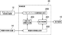
- the control device 20 of the nibbler heavy machine has a projection direction information generation unit 203.
- the projection direction information generation unit 203 automatically generates projection direction information based on the three-dimensional shape information and the attachment position information (step 5b shown in FIG. 9).
- the three-dimensional shape information is information generated by the surrounding shape information generation unit 202, information on the three-dimensional shape of the surrounding work area, and information including a three-dimensional shape corresponding to a building.
- the attachment position information is information generated by the attachment position information generation unit 200, and includes position information related to the position of at least the tip attachment (for example, the nibbler 54) of the attachment 50. A more detailed function of the projection direction information generation unit 203 will be described below.
- the control device 20 can determine whether an object is present near the tip attachment (nibra 54) based on the three-dimensional shape information (peripheral shape information) and the attachment position information. In the specific example shown in FIG. 6, the control device 20 determines that the wall surface 60b of the building exists near the nibler 54, and the shortest distance between the nibler 54 and the wall surface 60b of the building is X as shown in FIG. It is.
- the projection direction information generation unit 203 stores a reference point 54a of a tip attachment that is set in advance.
- the reference point 54a is set at the center of the nibler 54, for example, but is not limited thereto, and may be set at a position shifted from the center.
- the projection direction information generation unit 203 stores a plurality of preset directions.
- Each of the plurality of directions is a direction based on a predetermined specific part in a nibble heavy machine (construction machine) for building demolition.
- the specific part is set, for example, in any part of the main body of the nibbler heavy machine.
- Examples of the main body of the nibbler heavy machine include the upper swing body 3 or the lower traveling body 1.
- the plurality of directions include, for example, the front, rear, upper, and lower sides indicated by the four black arrows shown in FIG.
- the projection direction information generation unit 203 determines that the wall surface 60b of the building and the reference point 54a are in the plurality of directions (forward, backward, upward) with respect to the specific part. And the downward direction) are determined, and the direction as the determination result is automatically generated as projection direction information.
- the projection direction information is the front indicated by a white arrow in FIG.
- the projection direction information is generated not only when the projection direction information is forward as described above, but also based on the surrounding shape information and the attachment position information.
- the unit 203 can automatically generate appropriate projection direction information (projection direction information in an arbitrary direction).
- the attachment related information in this embodiment is calculated based on the shape information of the tip attachment 54, the attachment position information, and the three-dimensional shape information.
- the attachment-related information includes a surrounding image 60 that is an image corresponding to the three-dimensional shape of the surrounding work area, a projection image 70 obtained by projecting an image corresponding to the nibler 54 onto the surrounding image 60 in the projection direction, This is information corresponding to the image overlaid.
- the surrounding image 60 includes an image corresponding to a building existing in the surrounding work area.
- the projection direction is not only forward, but the projection direction information generation unit 203 automatically generates appropriate projection direction information based on the surrounding shape information and the attachment position information. Is possible.
- the attachment-related information is information corresponding to an image in which the projection image 70 of the tip attachment (nibler 54) is superimposed on the surrounding image 60 corresponding to the three-dimensional shape of the surrounding work area.
- the projection image 70 includes distance information calculated (generated) by the display control unit 201 of the control device 20.
- the distance information is information relating to the distance between the nibbler 54 and a portion corresponding to a portion where the surrounding image 60 and the projected image 70 overlap among objects existing in the surrounding work area.
- the projected image 70 is an image calculated (generated) by the display control unit 201, and is a projected image expressed in shades of color according to the distance information.
- the projected image 70 expressed by the color shading will be described in more detail with reference to FIG.
- the projection image 70 included in the image displayed on the screen of the display device 13 shown in FIG. 6 is a projection image expressed in the shades of the color, for example, a projection image expressed in the shades of black and white.
- the projection direction (projection direction indicated by a white arrow) may be set, for example, in a direction in which the nibler 54 approaches a part of the wall surface 6 b that is the target position of the building existing at the work site. .
- the projection image 70 is, for example, black and white according to distance information regarding the distance between the nibler 54 and a part corresponding to a portion of the building existing on the work site where the surrounding image 60 and the projection image 70 overlap. Expressed in shades. For example, the projected image 70 is expressed so that the color becomes darker as the distance between the building and the nibbler 54 becomes smaller, that is, as the two approach each other.
- the display control unit 201 displays a position for superimposing and displaying the projection image 70 on the surrounding image 60 based on the projection direction, the shape information of the attachment, the attachment position information, and the three-dimensional shape information. Calculate. Then, the display control unit 201 displays the projection image 70 on the surrounding image 60 on the display device 13 as shown in FIG.
- a tip attachment (book) to a target position (part of a wall surface) in a surrounding work area, specifically, for example, a building existing in a target work site.
- the nibbler 54 approach is more intuitively understood by the operator.
- the nibbler heavy machine according to the present embodiment has a guidance function that makes it easier for the operator to work.
- the tip attachment is the nibbler 54.
- the tip attachment may be various tip attachments other than the nibbler 54.
- the projection direction information generation unit 203 automatically generates the projection direction information related to the projection direction based on the surrounding shape information and the attachment position information.
- the projection direction information generation unit 203 automatically generates projection direction information for setting the movement direction of a specific part of the attachment 50, specifically, for example, the movement direction of the tip of the tip attachment as the projection direction. It may be configured.
- the attachment position information generation unit 200 generates attachment position information at a specific time point (for example, current) and attachment position information a predetermined time before the specific time point, and based on the attachment position information.
- the moving direction of the tip of the tip attachment (nibler 54) may be calculated, and projection direction information may be generated with the moving direction as the projection direction.
- the projection direction information generation unit 203 projects the projection direction information calculated a predetermined time before the specific time (for example, the present time). It may be generated as direction information.
- the specific part of the attachment 50 is not limited to the tip of the nibler 54, and is set, for example, at the tip of the bucket 6 shown in FIG. 1 or the tip of the arm 5 (for example, a position indicated by reference numeral 12c).
- the projection direction information generation unit 203 calculates the movement direction of the set specific part, and generates projection direction information with the movement direction as the projection direction.
- FIG. 3 10 is a side view showing a schematic configuration of a hydraulic excavator as a construction machine according to Embodiment 3 of the present invention
- FIG. 11 is a block diagram showing main functions of the hydraulic excavator shown in FIG.
- the surrounding shape detection apparatus 14 installed in the ceiling part of the cab 10 shown in FIG. 1 in the said Embodiment 1 is abbreviate
- the function performed by the surrounding shape detection device 14 is realized by the following three components shown in FIGS. 10 and 11 instead of the surrounding shape detection device 14.
- the first component is a storage device 17 that stores three-dimensional shape information (three-dimensional shape data of a construction site) of a surrounding work area prepared by photographing using a photographing device such as a drone in advance.
- the second component is a receiver 18 capable of receiving data related to a satellite positioning system such as GPS and GSNN, for example.
- the receiver 18 receives the data related to the satellite positioning system, thereby receiving the vehicle position information. Can be obtained.
- the third component is the upper swing body state detection device 16.
- the upper turning body state detection device 16 is installed in the turning mechanism 2, for example.
- the upper swing body state detection device 16 is configured by an orientation sensor for detecting the direction in which the upper swing body 3 faces, for example.
- the surrounding shape information generation unit 202 is detected by the three-dimensional shape data stored in the storage device 17, the vehicle position information acquired by the receiver 18, and the upper turning body state detection device 16. 3D shape information (peripheral shape information) of the surrounding work area is generated based on the information regarding the orientation of the upper swing body 3.
- the function performed by the surrounding shape detection device 14 illustrated in FIG. 1 is realized using the storage device 17, the receiver 18, and the upper swing body state detection device 16. It is not limited to these.
- the second component and the third component may be replaced by other components. Examples of such other components include a receiver capable of receiving data related to the satellite positioning system.
- the function of the surrounding shape detection device 14 shown in FIG. 1 is to use the three-dimensional shape information (three-dimensional shape data of the construction site) of the surrounding work area prepared by photographing using a photographing device such as a drone beforehand.
- a storage device 17 that stores data, a receiver 18 that can acquire vehicle position information by receiving data related to the satellite positioning system, and a direction of the upper turning body 3 by receiving data related to the satellite positioning system. And a receiver capable of acquiring information about the. That is, a plurality of receivers that can receive data related to the satellite positioning system can realize the functions of the second component and the third component.
- FIG. 12 is a side view showing a schematic configuration of a hydraulic excavator as a construction machine according to Embodiment 4 of the present invention.
- the display device in the fourth embodiment is different from the display device 13 provided on the front side in the cab 10 shown in FIG. 1 in the first embodiment.
- the display device 110 according to the fourth embodiment includes a glasses-type transmissive head-mounted display (glasses-type transmissive HMD) worn by the operator 100 in the cab 10 shown in FIG.
- glasses-type transmissive head-mounted display glasses-type transmissive HMD
- the tip attachment buckle 6
- the hydraulic excavator according to the present embodiment has a guidance function that facilitates the operation for the operator.
- the hydraulic excavator according to the fourth embodiment also has an advantage that it is not necessary to install a large transmission type HUD like the display device 13 in the first embodiment on the front side in the cab 10.
- the transmissive HUD as the display device 13 described in the first to third embodiments and the glasses-type transmissive HMD as the display device 110 described in the fourth embodiment are both used in the cab 10.
- the display device is a premise, the display device according to the present invention is not necessarily present in the cab 10 and may be disposed outside the cab 10.
- the display device may be configured by a remote operation support monitor for an operator to remotely operate a hydraulic excavator (construction machine) outside the cab 10 using a remote operation device. Details of the remote operation support monitor will be described later in Embodiment 5 and Embodiment 6.
- the hydraulic excavator has a guidance function that makes it easy for the operator to work. And when an operator utilizes the said guidance function, it becomes unnecessary to move a viewpoint from the target work site, and the fall of work efficiency is suppressed.
- the remote operation support monitor when employed, the operator does not necessarily need to be at the actual work site, and remotely operates the construction machine in the building where the remote operation support monitor is set. It becomes possible. Thus, there is an effect that the degree of freedom of the place where the operator actually works is also increased.
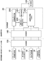
- FIG. 13 is a block diagram showing main functions of a hydraulic excavator as a construction machine according to Embodiment 5 of the present invention.
- the hydraulic excavator according to the fifth embodiment is different from the hydraulic excavator according to the third embodiment in that it has a configuration that can be remotely operated, and is otherwise the same as the hydraulic excavator according to the third embodiment. is there.
- the display device 120 is arranged not in the cab 10 of the excavator but in a remote place outside the cab 10.
- the hydraulic excavator according to the fifth embodiment includes a construction machine main body and a remote control unit.
- the construction machine main body includes the control device 20, the attachment state detection device 12, the storage device 17, the receiver 18, the upper swing body state detection device 16, and a transmission device 130.
- the remote control unit includes a display device 120 and a receiving device 140.
- the control device 20 and the display device 120 are mechanically separated.
- the control device 20 and the display device 120 are connected to each other via wireless communication.
- the display device 120 according to the fifth embodiment is a remote operation support monitor for an operator to remotely operate a hydraulic excavator (construction machine) outside the cab 10 using a remote operation device. . Therefore, this feature point will be described in detail below, and the same components as those in the third embodiment will be denoted by the same reference numerals and detailed description thereof will be omitted.
- the display device 120 in the hydraulic excavator is a remote operation support monitor for remotely operating the hydraulic excavator (construction machine) outside the cab 10.
- the transmission device 130 is provided in a construction machine main body (hydraulic excavator main body), and a signal output from the display control unit 201 is input to the transmission device 130.
- the receiving device 140 is provided in the remote control unit and receives a signal transmitted from the transmitting device 130. A signal received by the receiving device 140 is input to the display device 120.
- the display device 120 displays an image related to the input signal.
- the hydraulic excavator according to the fifth embodiment is configured such that information similar to the attachment-related information in the first embodiment is transmitted from the transmission device 130 to the reception device 140 by wireless communication.
- wireless communication include communication using radio waves, such as communication using a mobile phone network and communication using a wireless LAN.
- the attachment related information is generated in the construction machine main body of the hydraulic excavator.
- the attachment related information is generated based on the attachment position information and the three-dimensional shape information.
- the attachment-related information is an image (attachment-related image) obtained by superimposing a surrounding image that is an image corresponding to the three-dimensional shape of the surrounding work area and a projection image obtained by projecting an image corresponding to the tip attachment in the projection direction. ).
- the attachment related information is transmitted to the display device 120 (the remote operation support monitor) in the remote operation unit via the transmission device 130 and the reception device 140.
- the display device 120 (the remote operation support monitor) displays the received image. Therefore, it is possible to simplify the devices constituting the display device 120 (the remote operation support monitor).
- FIG. 14 is a block diagram showing main functions of a hydraulic excavator as a construction machine according to Embodiment 6 of the present invention.
- the hydraulic excavator according to the sixth embodiment is different from the hydraulic excavator according to the fifth embodiment in that the control device 20 is provided not in the construction machine body but in the remote control unit, and in other respects the fifth embodiment. It is the same as that of the hydraulic excavator concerning.
- the construction machine main body receives the vehicle position information by receiving data related to the attachment state detection device 12, the storage device 17 for storing the three-dimensional shape data of the construction site, and a satellite positioning system such as GPS.
- the receiver 18 which can be acquired, the upper turning body state detection apparatus 16, and the transmission apparatus 150 are included.
- the remote control unit includes a receiving device 160, the control device 20, and the display device 120.
- the attachment state detection device 12, the storage device 17, the receiver 18, the upper swing body state detection device 16, and the control device 20 are mechanically separated and connected to each other via wireless communication. It is characterized by that. Therefore, this feature point will be described in detail below, and the same components as those in the fifth embodiment will be denoted by the same reference numerals and detailed description thereof will be omitted.
- the transmission device 150 is provided in a construction machine main body (hydraulic excavator main body), and the transmission device 150 includes attachment basic data relating to the attachment state detected by the attachment state detection device 12, and Peripheral work area basic data serving as a basis for the three-dimensional shape information of the peripheral work area is input.
- the surrounding work area basic data is, for example, the construction site three-dimensional shape data stored in the storage device 17, the vehicle position information by the receiver 18, and the upper part detected by the upper turning body state detection device 16.
- the receiving device 160 is provided in the remote control unit, and receives the attachment basic data and the surrounding work area basic data transmitted from the transmitting device 150 via wireless communication.
- the attachment position information generation unit 200 generates attachment position information based on the attachment basic data received by the receiving device 160.
- the surrounding shape information generation unit 202 generates 3D shape information of the surrounding work area based on the surrounding work area basic data received by the receiving device 160.
- the display control unit 201 is configured to generate attachment-related information based on the attachment position information and the three-dimensional shape information, and to display the attachment-related information on the display device 120 (the remote operation support monitor). Is configured to do.
- the remote In the operation unit based on the attachment basic data and the surrounding work area basic data transmitted from the transmission device 150 provided in the construction machine main body (hydraulic excavator main body), the remote In the operation unit, the attachment related information is generated. Therefore, it is not necessary to mount a processing device for generating the image in a hydraulic excavator main body (construction machine main body) that generates more vibration and impact than the remote control unit. For this reason, the structure in a hydraulic shovel main body (construction machine main body) can be simplified.
- the attachment-related information projects a surrounding image that is an image corresponding to the three-dimensional shape of the surrounding work area and an image corresponding to the tip attachment in the projection direction with respect to the surrounding image.
- the information corresponding to the image superimposed with the projected image is not necessarily limited to this.
- the attachment related information according to the present invention may be information regarding an image obtained by projecting at least an image corresponding to the tip attachment to the surrounding image in the projection direction with respect to the surrounding image.
- the present inventors have earnestly studied how an approach of attachment to a target position in a surrounding work area (target work site) can realize a construction machine having an easy guidance function for an operator. Went. As a result, it has been found that the object can be achieved only by adopting various configurations as described below.
- the construction machine includes an attachment including a tip attachment.
- the construction machine includes an attachment state detection device that detects the state of the attachment, and attachment position information that generates attachment position information that is information regarding the position of the attachment based on the state of the attachment detected by the attachment state detection device.
- Attachment generated based on three-dimensional shape information which is information on the three-dimensional shape of the surrounding work area of the construction machine and the attachment position information generated by the generation unit, the display device, and the attachment position information generation unit
- a display control unit that performs control to display related information on the display device.
- the attachment-related information is a projection set based on a projection direction arbitrarily set or a predetermined condition of a surrounding image that is an image corresponding to the three-dimensional shape of the surrounding work area and an image corresponding to the tip attachment. This is information corresponding to an image obtained by superimposing a projection image projected on the surrounding image in the direction.
- the operator confirms the attachment related information displayed on the display device.
- an operation for bringing the tip attachment closer to the target position in the surrounding work area (target work site) can be performed. Therefore, according to the present invention, it is possible to provide a construction machine having a guidance function that makes it easy for the operator to approach the target work position in the surrounding work area.
- the display control unit can calculate a relative position of the tip attachment with respect to an object existing in the surrounding work area based on the attachment position information and the three-dimensional shape information.
- the display control unit may generate the surrounding image based on the three-dimensional shape information, and based on the relative position, an image corresponding to the tip attachment may be projected in the projection direction with respect to the surrounding image. Therefore, the display control unit can generate an image (superimposed image) obtained by superimposing the surrounding image and the projection image. Therefore, the display control unit can generate the attachment related information based on the attachment position information and the three-dimensional shape information, and can perform control to display the attachment related information on the display device. it can.
- the projection image is a color corresponding to distance information related to a distance between the tip attachment and a portion corresponding to a portion where the surrounding image and the projection image overlap among objects existing in the surrounding work area. It is preferable that the color is expressed by the shade or color type.
- the projected image is expressed by color shades or color types according to the distance information. This makes it easy for the operator to intuitively recognize the distance information based on the color shade or the color type.
- the display control unit can calculate the relative position of the tip attachment with respect to the object existing in the surrounding work area based on the attachment position information and the three-dimensional shape information. . Further, the display control unit can calculate a distance between the tip attachment and the part of the object based on the relative position. Therefore, the display control unit can generate the projection image represented by color shades or color types according to the distance information based on the attachment position information and the three-dimensional shape information.
- the construction machine includes a surrounding shape detection device that detects the three-dimensional shape of the surrounding work area, and the surrounding work area based on the three-dimensional shape of the surrounding work area detected by the surrounding shape detection device. It is preferable to further include a surrounding shape information generation unit that generates three-dimensional shape information.
- the surrounding shape information generation unit since the surrounding shape information generation unit generates the three-dimensional shape information based on the three-dimensional shape of the surrounding work area detected by the surrounding shape detection device, the construction machine can perform the target work. It is not necessary to store the three-dimensional shape information of the surrounding work area at the site as data before starting the work.
- the surrounding shape detection device may be configured to detect the shape of the tip attachment.
- the construction machine is detected by the surrounding shape detection device. Based on the shape of the second tip attachment, the shape information of the second tip attachment can be acquired. This enables the shape information of the tip attachment to be updated to the latest information even when the tip attachment is replaced.
- the surrounding shape detection device since the surrounding shape detection device has a function of detecting the three-dimensional shape of the surrounding work area and a function of detecting the shape of the tip attachment, the configuration of the construction machine is complicated. Can be suppressed.
- the attachment state detection device may be configured to detect the three-dimensional shape of the surrounding work area.
- the attachment state detection device since the attachment state detection device has a function of detecting the state of the attachment and a function of detecting the three-dimensional shape of the surrounding work area, the three-dimensional shape of the surrounding work area is detected.
- a device for performing the above for example, the surrounding shape detection device as described above
- the display device may be a transmissive head-up display provided on the front side in the cab.
- the display device is a transmissive head-up display
- an area for displaying the attachment-related information can be set relatively freely compared to the case where the display device is a liquid crystal display, for example. It can suppress that an operator's visual field is obstruct
- the display device may be a transmissive head mounted display configured to be worn by an operator in a cab.
- the display device is a head-mounted display, it is possible to prevent the field of view of the operator from being blocked as compared with a case where the display device is a liquid crystal display, for example.
- the head mounted display is a transmission type, the visual information obtained by the operator is not limited to the information displayed on the head mounted display, and the visual information of the operator is transmitted through the head mounted display. Information that acts is also included. Therefore, the operator can perform, for example, a switch operation for operating a switch in the cab without being obstructed by the head mounted display.
- the construction machine includes a transmission device provided in a construction machine main body including the attachment, and a reception device provided in a remote operation unit for remotely operating the construction machine main body outside a cab of the construction machine main body.
- the display device is a remote operation support monitor provided in the remote operation unit, and a signal related to the attachment-related information output from the display control unit is wirelessly transmitted from the transmission device to the reception device.
- the remote operation support monitor may be configured to display the attachment related information based on the signal transmitted by communication and received by the receiving device.
- the operator does not necessarily have to go to the actual work site, and can remotely operate the construction machine at the remote operation unit provided in a remote place away from the work site.
- the construction machine is a transmission device provided in a construction machine main body including the attachment, the attachment basic data regarding the state of the attachment detected by the attachment state detection device, and the three-dimensional shape information of the surrounding work area
- the attachment basic data and the surrounding work area basic data transmitted from the transmission device are received by wireless communication, and the remote operation unit is provided with the surrounding work area basic data received by the receiving device.
- the display device Surrounding shape information for generating the 3D shape information of the surrounding work area based on
- the display device is a remote operation support monitor provided in the remote operation unit, and the attachment position information generation unit is provided in the remote operation unit and is received by the reception device.
- the attachment control unit generates attachment position information based on the attached attachment basic data
- the display control unit is provided in the remote operation unit, and is configured to perform control to display the attachment related information on the remote operation support monitor May be.
- the operator does not necessarily have to go to the actual work site, and can remotely operate the construction machine at the remote control unit provided in a remote place away from the work site.
- the attachment position information generation unit and the surrounding shape information generation unit are provided in the remote operation unit, the attachment position information and the three-dimensional shape information are generated in the remote operation unit. . That is, in this aspect, it is not necessary to mount the processing devices that constitute the attachment position information generation unit and the surrounding shape information generation unit on a construction machine main body that generates a lot of vibration and impact.
Priority Applications (3)
| Application Number | Priority Date | Filing Date | Title |
|---|---|---|---|
| EP19777544.8A EP3754122A4 (en) | 2018-03-28 | 2019-03-27 | CONSTRUCTION MACHINE |
| US16/981,949 US11421404B2 (en) | 2018-03-28 | 2019-03-27 | Construction machine |
| CN201980020549.8A CN111868340A (zh) | 2018-03-28 | 2019-03-27 | 工程机械 |
Applications Claiming Priority (2)
| Application Number | Priority Date | Filing Date | Title |
|---|---|---|---|
| JP2018061613A JP7087545B2 (ja) | 2018-03-28 | 2018-03-28 | 建設機械 |
| JP2018-061613 | 2018-03-28 |
Publications (1)
| Publication Number | Publication Date |
|---|---|
| WO2019189430A1 true WO2019189430A1 (ja) | 2019-10-03 |
Family
ID=68059095
Family Applications (1)
| Application Number | Title | Priority Date | Filing Date |
|---|---|---|---|
| PCT/JP2019/013304 WO2019189430A1 (ja) | 2018-03-28 | 2019-03-27 | 建設機械 |
Country Status (5)
| Country | Link |
|---|---|
| US (1) | US11421404B2 (zh) |
| EP (1) | EP3754122A4 (zh) |
| JP (1) | JP7087545B2 (zh) |
| CN (1) | CN111868340A (zh) |
| WO (1) | WO2019189430A1 (zh) |
Cited By (2)
| Publication number | Priority date | Publication date | Assignee | Title |
|---|---|---|---|---|
| WO2022070707A1 (ja) * | 2020-09-29 | 2022-04-07 | 株式会社小松製作所 | 表示制御装置及び表示方法 |
| EP4072130A4 (en) * | 2020-01-30 | 2023-03-22 | Kobelco Construction Machinery Co., Ltd. | WORK ASSISTANCE SYSTEM AND WORK ASSISTANCE METHOD |
Families Citing this family (8)
| Publication number | Priority date | Publication date | Assignee | Title |
|---|---|---|---|---|
| JP7080750B2 (ja) * | 2018-06-29 | 2022-06-06 | 株式会社小松製作所 | 表示制御システム、遠隔操作システム、表示制御装置、および表示制御方法 |
| JP7285051B2 (ja) * | 2018-06-29 | 2023-06-01 | 株式会社小松製作所 | 表示制御装置、および表示制御方法 |
| JP2021070922A (ja) * | 2019-10-29 | 2021-05-06 | 住友重機械工業株式会社 | ショベル |
| KR102415420B1 (ko) * | 2019-11-29 | 2022-07-04 | 한국생산기술연구원 | 굴삭기의 버켓 위치 확인 시스템 이를 이용한 버켓 위치 확인 방법 |
| JP2021130973A (ja) * | 2020-02-20 | 2021-09-09 | 株式会社フジタ | 情報提示システム |
| JP2021143541A (ja) * | 2020-03-13 | 2021-09-24 | コベルコ建機株式会社 | 作業支援サーバ、作業支援方法 |
| KR102417984B1 (ko) * | 2020-05-11 | 2022-07-08 | 한국생산기술연구원 | 굴삭기의 운전자 보조시스템 및 이를 이용한 굴삭기 제어 방법 |
| DE102020206925A1 (de) | 2020-06-03 | 2021-12-09 | Robert Bosch Gesellschaft mit beschränkter Haftung | Verfahren und System zum Visualisieren von dreidimensionalen Arbeitsbereichsbegrenzungen in einem Sichtfeld eines Bedieners einer mobilen Arbeitsmaschine |
Citations (6)
| Publication number | Priority date | Publication date | Assignee | Title |
|---|---|---|---|---|
| JPS5941663B2 (ja) | 1979-07-20 | 1984-10-08 | 住友化学工業株式会社 | 樹脂組成物の製造法 |
| JPH06272282A (ja) * | 1993-03-22 | 1994-09-27 | Fujita Corp | 掘削装置の遠隔操作システム |
| JP2001123476A (ja) * | 1999-10-26 | 2001-05-08 | Hitachi Constr Mach Co Ltd | 掘削機械の表示システム及び記録媒体 |
| WO2014054193A1 (ja) * | 2012-10-05 | 2014-04-10 | 株式会社小松製作所 | 掘削機械の表示システム及び掘削機械 |
| JP2017071942A (ja) | 2015-10-06 | 2017-04-13 | 日立建機株式会社 | 建設機械 |
| WO2017170382A1 (ja) * | 2016-03-30 | 2017-10-05 | 住友建機株式会社 | ショベル |
Family Cites Families (18)
| Publication number | Priority date | Publication date | Assignee | Title |
|---|---|---|---|---|
| EP0929058B1 (en) * | 1992-07-23 | 2005-11-23 | Aisin Aw Co., Ltd. | Vehicle route guidance apparatus for researching for a route when vehicle goes out of route |
| CN102348100A (zh) * | 2010-07-30 | 2012-02-08 | 江彦宏 | 视讯雷达显示系统 |
| JP5124671B2 (ja) * | 2011-06-07 | 2013-01-23 | 株式会社小松製作所 | 作業車両の周辺監視装置 |
| JP5802476B2 (ja) * | 2011-08-09 | 2015-10-28 | 株式会社トプコン | 建設機械制御システム |
| JP5941663B2 (ja) | 2011-11-30 | 2016-06-29 | 住友建機株式会社 | 建設機械用モニタシステム |
| US8914199B2 (en) | 2012-10-05 | 2014-12-16 | Komatsu Ltd. | Excavating machine display system and excavating machine |
| US8918246B2 (en) * | 2012-12-27 | 2014-12-23 | Caterpillar Inc. | Augmented reality implement control |
| US20140226024A1 (en) * | 2013-02-08 | 2014-08-14 | Kutta Technologies, Inc. | Camera control in presence of latency |
| US8731824B1 (en) * | 2013-03-15 | 2014-05-20 | Honda Motor Co., Ltd. | Navigation control for a touch screen user interface |
| JP2015043488A (ja) | 2013-08-26 | 2015-03-05 | 清水建設株式会社 | 遠隔操作装置及びそれを用いた遠隔施工方法 |
| DE102014222198A1 (de) | 2014-10-30 | 2016-05-04 | Wacker Chemie Ag | Verfahren zur Herstellung eines Candy-Gums |
| EP3020868B1 (en) * | 2014-11-14 | 2020-11-04 | Caterpillar Inc. | Machine of a kind comprising a body and an implement movable relative to the body with a system for assisting a user of the machine |
| JP6777375B2 (ja) | 2015-03-05 | 2020-10-28 | 株式会社小松製作所 | 作業機械の画像表示システム、作業機械の遠隔操作システム及び作業機械 |
| CN107429502A (zh) | 2015-03-27 | 2017-12-01 | 住友建机株式会社 | 挖土机 |
| JP6707344B2 (ja) * | 2015-12-25 | 2020-06-10 | 株式会社小松製作所 | 作業車両および作業車両の制御方法 |
| US10200659B2 (en) * | 2016-02-29 | 2019-02-05 | Microsoft Technology Licensing, Llc | Collaborative camera viewpoint control for interactive telepresence |
| JP6794193B2 (ja) * | 2016-09-02 | 2020-12-02 | 株式会社小松製作所 | 作業機械の画像表示システム |
| US11110915B2 (en) * | 2017-08-31 | 2021-09-07 | Panasonic Automotive Systems Company Of America, Division Of Panasonic Corporation Of North America | Auto park human machine interface display based control |
-
2018
- 2018-03-28 JP JP2018061613A patent/JP7087545B2/ja active Active
-
2019
- 2019-03-27 EP EP19777544.8A patent/EP3754122A4/en active Pending
- 2019-03-27 WO PCT/JP2019/013304 patent/WO2019189430A1/ja unknown
- 2019-03-27 CN CN201980020549.8A patent/CN111868340A/zh active Pending
- 2019-03-27 US US16/981,949 patent/US11421404B2/en active Active
Patent Citations (6)
| Publication number | Priority date | Publication date | Assignee | Title |
|---|---|---|---|---|
| JPS5941663B2 (ja) | 1979-07-20 | 1984-10-08 | 住友化学工業株式会社 | 樹脂組成物の製造法 |
| JPH06272282A (ja) * | 1993-03-22 | 1994-09-27 | Fujita Corp | 掘削装置の遠隔操作システム |
| JP2001123476A (ja) * | 1999-10-26 | 2001-05-08 | Hitachi Constr Mach Co Ltd | 掘削機械の表示システム及び記録媒体 |
| WO2014054193A1 (ja) * | 2012-10-05 | 2014-04-10 | 株式会社小松製作所 | 掘削機械の表示システム及び掘削機械 |
| JP2017071942A (ja) | 2015-10-06 | 2017-04-13 | 日立建機株式会社 | 建設機械 |
| WO2017170382A1 (ja) * | 2016-03-30 | 2017-10-05 | 住友建機株式会社 | ショベル |
Non-Patent Citations (1)
| Title |
|---|
| See also references of EP3754122A4 |
Cited By (2)
| Publication number | Priority date | Publication date | Assignee | Title |
|---|---|---|---|---|
| EP4072130A4 (en) * | 2020-01-30 | 2023-03-22 | Kobelco Construction Machinery Co., Ltd. | WORK ASSISTANCE SYSTEM AND WORK ASSISTANCE METHOD |
| WO2022070707A1 (ja) * | 2020-09-29 | 2022-04-07 | 株式会社小松製作所 | 表示制御装置及び表示方法 |
Also Published As
| Publication number | Publication date |
|---|---|
| EP3754122A1 (en) | 2020-12-23 |
| CN111868340A (zh) | 2020-10-30 |
| US11421404B2 (en) | 2022-08-23 |
| US20210010244A1 (en) | 2021-01-14 |
| EP3754122A4 (en) | 2021-03-31 |
| JP2019173352A (ja) | 2019-10-10 |
| JP7087545B2 (ja) | 2022-06-21 |
Similar Documents
| Publication | Publication Date | Title |
|---|---|---|
| WO2019189430A1 (ja) | 建設機械 | |
| AU2018333191B2 (en) | Display system, display method, and display apparatus | |
| AU2017404218B2 (en) | Display system, display method, and remote operation system | |
| US20140111648A1 (en) | Device For Monitoring Area Around Working Machine | |
| JP6832548B2 (ja) | 作業機械の画像表示システム、作業機械の遠隔操作システム、作業機械及び作業機械の画像表示方法 | |
| JP2018014554A (ja) | 作業車 | |
| EP3252238B1 (en) | User interface for an earth-moving machine | |
| JP2006053922A (ja) | 機械操作者にとっての視認性を高める方法及び装置 | |
| US11874659B2 (en) | Information system for a working machine | |
| JP2016181119A (ja) | 移動機器の周囲状況提示システム | |
| US20210025131A1 (en) | Remote control system and main control device | |
| WO2020066475A1 (ja) | 作業機械情報表示システム | |
| WO2018228669A1 (en) | A working machine provided with an image projection arrangement | |
| JP2017046277A (ja) | 作業機械の周囲監視装置 | |
| JP7076501B2 (ja) | 作業車 | |
| WO2020194882A1 (ja) | 遠隔操作システムおよび遠隔操作サーバ | |
| US11939744B2 (en) | Display system, remote operation system, and display method | |
| KR102279247B1 (ko) | 증강 현실 방법을 이용하여 장비를 원격 제어하는 가상 현실 구현 장치 및 그 방법 및 이를 이용한 관리 시스템 | |
| WO2023136070A1 (ja) | 遠隔操作支援システムおよび遠隔操作支援方法 | |
| KR20220132753A (ko) | 굴착기에서 타겟 객체에 대한 거리를 측정하는 장치 및 그의 동작 방법 | |
| JP2021155949A (ja) | 作業機械 | |
| JP2023032997A (ja) | 遠隔操作システム | |
| JP2021170719A (ja) | 情報表示装置及び情報表示プログラム |
Legal Events
| Date | Code | Title | Description |
|---|---|---|---|
| 121 | Ep: the epo has been informed by wipo that ep was designated in this application |
Ref document number: 19777544 Country of ref document: EP Kind code of ref document: A1 |
|
| NENP | Non-entry into the national phase |
Ref country code: DE |
|
| ENP | Entry into the national phase |
Ref document number: 2019777544 Country of ref document: EP Effective date: 20200917 |