WO2019189430A1 - 建設機械 - Google Patents
建設機械 Download PDFInfo
- Publication number
- WO2019189430A1 WO2019189430A1 PCT/JP2019/013304 JP2019013304W WO2019189430A1 WO 2019189430 A1 WO2019189430 A1 WO 2019189430A1 JP 2019013304 W JP2019013304 W JP 2019013304W WO 2019189430 A1 WO2019189430 A1 WO 2019189430A1
- Authority
- WO
- WIPO (PCT)
- Prior art keywords
- attachment
- construction machine
- surrounding
- information
- image
- Prior art date
Links
- 238000010276 construction Methods 0.000 title claims abstract description 95
- 238000001514 detection method Methods 0.000 claims description 73
- 230000005540 biological transmission Effects 0.000 claims description 20
- 238000004891 communication Methods 0.000 claims description 12
- 241000030361 Girellinae Species 0.000 description 17
- 238000013459 approach Methods 0.000 description 16
- 238000010586 diagram Methods 0.000 description 14
- 230000002093 peripheral effect Effects 0.000 description 9
- 238000012545 processing Methods 0.000 description 7
- 238000000034 method Methods 0.000 description 5
- 230000000694 effects Effects 0.000 description 4
- 239000003550 marker Substances 0.000 description 4
- 230000000007 visual effect Effects 0.000 description 4
- 239000003086 colorant Substances 0.000 description 3
- 238000012905 input function Methods 0.000 description 2
- 239000004973 liquid crystal related substance Substances 0.000 description 2
- 241001482107 Alosa sapidissima Species 0.000 description 1
- 230000003190 augmentative effect Effects 0.000 description 1
- 238000004364 calculation method Methods 0.000 description 1
- 238000013461 design Methods 0.000 description 1
Images


Classifications
-
- E—FIXED CONSTRUCTIONS
- E02—HYDRAULIC ENGINEERING; FOUNDATIONS; SOIL SHIFTING
- E02F—DREDGING; SOIL-SHIFTING
- E02F9/00—Component parts of dredgers or soil-shifting machines, not restricted to one of the kinds covered by groups E02F3/00 - E02F7/00
- E02F9/26—Indicating devices
- E02F9/261—Surveying the work-site to be treated
- E02F9/262—Surveying the work-site to be treated with follow-up actions to control the work tool, e.g. controller
-
- E—FIXED CONSTRUCTIONS
- E02—HYDRAULIC ENGINEERING; FOUNDATIONS; SOIL SHIFTING
- E02F—DREDGING; SOIL-SHIFTING
- E02F9/00—Component parts of dredgers or soil-shifting machines, not restricted to one of the kinds covered by groups E02F3/00 - E02F7/00
- E02F9/26—Indicating devices
- E02F9/261—Surveying the work-site to be treated
-
- G—PHYSICS
- G02—OPTICS
- G02B—OPTICAL ELEMENTS, SYSTEMS OR APPARATUS
- G02B27/00—Optical systems or apparatus not provided for by any of the groups G02B1/00 - G02B26/00, G02B30/00
- G02B27/01—Head-up displays
- G02B27/017—Head mounted
- G02B27/0172—Head mounted characterised by optical features
-
- E—FIXED CONSTRUCTIONS
- E02—HYDRAULIC ENGINEERING; FOUNDATIONS; SOIL SHIFTING
- E02F—DREDGING; SOIL-SHIFTING
- E02F9/00—Component parts of dredgers or soil-shifting machines, not restricted to one of the kinds covered by groups E02F3/00 - E02F7/00
- E02F9/20—Drives; Control devices
- E02F9/2025—Particular purposes of control systems not otherwise provided for
- E02F9/205—Remotely operated machines, e.g. unmanned vehicles
-
- G—PHYSICS
- G02—OPTICS
- G02B—OPTICAL ELEMENTS, SYSTEMS OR APPARATUS
- G02B27/00—Optical systems or apparatus not provided for by any of the groups G02B1/00 - G02B26/00, G02B30/00
- G02B27/01—Head-up displays
- G02B27/0101—Head-up displays characterised by optical features
- G02B2027/014—Head-up displays characterised by optical features comprising information/image processing systems
-
- G—PHYSICS
- G02—OPTICS
- G02B—OPTICAL ELEMENTS, SYSTEMS OR APPARATUS
- G02B27/00—Optical systems or apparatus not provided for by any of the groups G02B1/00 - G02B26/00, G02B30/00
- G02B27/01—Head-up displays
- G02B27/0101—Head-up displays characterised by optical features
- G02B2027/0141—Head-up displays characterised by optical features characterised by the informative content of the display
-
- G—PHYSICS
- G02—OPTICS
- G02B—OPTICAL ELEMENTS, SYSTEMS OR APPARATUS
- G02B27/00—Optical systems or apparatus not provided for by any of the groups G02B1/00 - G02B26/00, G02B30/00
- G02B27/01—Head-up displays
- G02B27/017—Head mounted
- G02B2027/0178—Eyeglass type
-
- H—ELECTRICITY
- H04—ELECTRIC COMMUNICATION TECHNIQUE
- H04N—PICTORIAL COMMUNICATION, e.g. TELEVISION
- H04N7/00—Television systems
- H04N7/18—Closed-circuit television [CCTV] systems, i.e. systems in which the video signal is not broadcast
- H04N7/183—Closed-circuit television [CCTV] systems, i.e. systems in which the video signal is not broadcast for receiving images from a single remote source
Definitions
- the present invention relates to a construction machine.
- Patent Document 1 There is known a technique for displaying distance information between a plane (reference position) on which a construction machine is located and the tip of an attachment as a number, together with the attachment, on a display device mounted in a cab of the construction machine (for example, Patent Document 1). reference).
- Patent Document 2 discloses a technique for displaying the necessary information on the display device by superimposing the necessary information as a character display or a color display on the side of the tip attachment.
- Patent Document 1 since distance information is displayed only with numbers, it is difficult for an operator to intuitively grasp the work situation, and in a surrounding work area (site) with unevenness and a slope. There is a problem that it is difficult to cope with work.
- Patent Document 2 only provides information necessary for the operation to be superimposed on the side of the tip attachment as a character display or a display including a color. Guidance function is not enough.
- An object of the present invention is to provide a construction machine having a guidance function that makes it easy for an operator to approach an attachment to a target position in a surrounding work area (target work site).
- a construction machine having an attachment including a tip attachment, an attachment state detection device for detecting the state of the attachment, and an attachment state based on the state of the attachment detected by the attachment state detection device
- Attachment position information generating unit for generating attachment position information, which is information about the position, display device, information on the attachment position information generated by the attachment position information generating unit, and information on the three-dimensional shape of the work area surrounding the construction machine
- a display control unit that controls the display device to display attachment related information generated based on the three-dimensional shape information.
- the attachment related information is set on the basis of a projection direction or a predetermined condition in which an ambient image that is an image corresponding to the three-dimensional shape of the surrounding work area and an image corresponding to the tip attachment are arbitrarily set. This is information corresponding to an image obtained by superimposing a projection image projected on the surrounding image in the projection direction.
- FIG. 1 is a side view showing a schematic configuration of a hydraulic excavator as a construction machine according to Embodiment 1 of the present invention. It is explanatory drawing for demonstrating the direction which projects the attachment of the hydraulic shovel shown in FIG. It is a block diagram which shows the main functions of the hydraulic shovel shown in FIG. It is a flowchart which shows the flow of the control processing which superimposes and displays the projection image of a tip attachment (bucket) on a surrounding image. It is a figure which shows the example which expressed the projection image of the bucket as a front-end
- FIG. 1 It is a figure which shows the example which expressed the projection image of the nibra as a tip attachment with the color shading in the screen of the display apparatus in the nibbler heavy machine as a construction machine concerning Embodiment 2 of this invention. It is explanatory drawing which expanded the A section in FIG. It is a block diagram which shows the main functions of the nibler heavy machine shown in FIG. It is a flowchart which shows the flow of the control processing which superimposes and displays the projection image of a tip attachment (nibra) on a surrounding image. It is a side view which shows schematic structure of the hydraulic shovel as a construction machine concerning Embodiment 3 of this invention. It is a block diagram which shows the main functions of the hydraulic shovel shown in FIG.
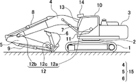
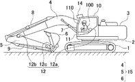
- FIG. 1 is a side view showing a schematic configuration of a hydraulic excavator as a construction machine according to Embodiment 1 of the present invention.
- FIG. 2 is an explanatory diagram for explaining a direction in which the attachment 15 of the excavator shown in FIG. 1 is projected.
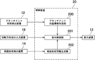
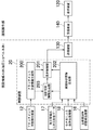
- FIG. 3 is a block diagram showing the main functions of the hydraulic excavator shown in FIG.
- FIG. 4 is a flowchart showing a flow of control processing for superimposing and displaying the projection image of the bucket 6 as the tip attachment of the attachment 15 shown in FIG. 1 on the surrounding image.
- FIG. 5 is a diagram illustrating an example in which a projected image of a bucket as a tip attachment is expressed in shades of color on a screen of a display device in the hydraulic excavator.
- the excavator includes a lower traveling body 1, an upper revolving body 3 that is turnably mounted on the lower traveling body 1, an attachment 15 that is attached to the upper revolving body 3, Is provided.
- the upper swing body 3 is mounted on the lower traveling body 1 via the swing mechanism 2.
- the attachment 15 includes a boom 4, an arm 5, and a bucket 6 (an example of a tip attachment).
- the boom 4 is attached to the upper swing body 3, the arm 5 is attached to the tip of the boom 4, and the bucket 6 is attached to the tip of the arm 5.
- the boom 4, the arm 5, and the bucket 6 are hydraulically driven by a boom cylinder 7, an arm cylinder 8, and a bucket cylinder 9, respectively.
- the upper swing body 3 is provided with a cab 10 and is mounted with a power source such as an engine.
- the hydraulic excavator further includes an attachment state detection device 12 that detects the state of the attachment 15 (step S1 shown in FIG. 4).
- the attachment state detection device 12 is mounted on, for example, the attachment 15 and the upper swing body 3.
- the attachment state detection device 12 is, for example, a sensor for acquiring information related to the state of the attachment 15 of the excavator.
- the attachment state detection device 12 includes a boom angle sensor 12 a that detects the tilt of the boom 4 with respect to the upper swing body 3, an arm angle sensor 12 b that detects the tilt of the arm 5 with respect to the boom 4, and a bucket with respect to the arm 5.
- 6 includes a bucket angle sensor 12c that detects the inclination of 6.
- the attachment state detection apparatus 12 contains said angle sensor, it is not necessarily limited to such a structure.
- the attachment state detection device 12 can be substituted with at least one of the following six configurations.
- a depth sensor that can acquire a three-dimensional image together with a distance to an object (attachment) 2.
- a combination of the depth sensor and a gyro sensor installed at the tip of the bucket 6.
- Stereo camera 5 Combination of the stereo camera and the gyro sensor Combination of the stereo camera, the gyro sensor, and the AR marker
- the excavator further includes a control device 20, a display device 13, and a surrounding shape detection device 14.
- the control device 20 and the display device 13 are installed, for example, inside the cab 10.
- the said surrounding shape detection apparatus 14 is installed in the ceiling part of the driver's cab 10, for example.
- the surrounding shape detection device 14 is a device capable of detecting the three-dimensional shape of the surrounding work area in front of the hydraulic excavator (for example, step S3 shown in FIG. 4).
- the surrounding work area is a work object (work site) located around the construction machine.
- the three-dimensional shape is also referred to as a “peripheral shape”.
- Examples of the display device 13 include a transmissive head-up display (hereinafter also referred to as “transmissive HUD”).
- the transmission type HUD is provided, for example, inside a windshield 11 disposed on the front surface of the cab 10 (also referred to as “front side in the cab 10”).
- the transmissive HUD as an example of the display device 13 is not necessarily separate from the windshield 11 and may be integrated with the windshield 11.
- the display device 13 may be a display other than the transmissive HUD.
- the surrounding shape detection device 14 for example, a distance image sensor (distance image camera) capable of acquiring a distance image having distance information for each pixel can be cited.
- a distance image sensor for example, a TOF type three-dimensional distance image sensor (for example, manufactured by Optics) capable of detecting a three-dimensional shape of a surrounding work area composed of a high-speed light source of a near infrared LED and a CMOS image sensor is cited. (TOF: Time of Flight).
- the surrounding shape detection device 14 may be a device other than the distance image sensor.
- 3 is composed of an attachment state detection device 12, a display device 13, a surrounding shape detection device 14, a projection direction instruction input device 19 and a control device 20.
- the projection direction instruction input device 19 has an input function for receiving input from an operator.
- the projection direction instruction input device 19 has a touch panel.
- the display screen of the touch panel includes a plurality of arrows indicating the side surface of the excavator and a direction in which the attachment 15 of the excavator is projected (hereinafter referred to as “projection direction”).
- projection direction a direction in which the attachment 15 of the excavator is projected
- eight arrows are displayed in an overlapping manner. Therefore, the operator can input a desired projection direction by selectively designating (clicking or touching) any one of the plurality of arrows displayed on the display screen.
- the control device 20 generates projection direction information based on input information related to the projection direction input by an operator.
- the projection direction instruction input device 19 is provided as a separate device from the display device 13, but is not necessarily limited thereto.
- the display device 13 may be provided with an input function that the projection direction instruction input device 19 has.
- the projection direction instruction input device 19 can be omitted.
- the projection direction is selectively input manually by an operator, and the control device 20 generates the projection direction information based on the input information regarding the projection direction.
- the present invention is not limited to this. Is not to be done.
- the input by the operator is omitted, and the control device 20 can automatically generate the projection direction information.
- the control device 20 is a computer including a CPU, a RAM, a ROM, and the like, for example. Specifically, the control device 20 includes an attachment position information generation unit 200, a display control unit 201, and a surrounding shape information generation unit 202 as functions.
- the attachment position information generation unit 200 generates information (attachment position information) related to the position of the attachment 15 based on the state of the attachment 15 detected by the attachment state detection device 12. Generate.
- the attachment position information generation unit 200 uses these sensors 12a, 12b, and 12c. Based on the detected signal, the posture of the attachment 15 can be calculated. Therefore, the attachment position information generation unit 200 can calculate the position of the tip attachment (bucket 6).
- the surrounding shape information generation unit 202 determines the three-dimensional shape of the surrounding work area based on the three-dimensional shape (around shape) of the surrounding work area detected by the surrounding shape detection device 14.
- Shape information (peripheral shape information) is generated.
- the surrounding shape information generation unit 202 can calculate the relative positions (coordinates) between the surrounding shape detection device 14 provided in the upper swing body 3 and a plurality of objects existing in the surrounding area. . Examples of the plurality of objects include ground, buildings, other vehicles, workers, and the like. Since the hydraulic excavator includes the surrounding shape detection device 14 and the surrounding shape information generation unit 202, the control device 20 acquires the surrounding shape information even if the surrounding shape information is not stored as data in advance. A system is provided.
- the display control unit 201 generates attachment related information based on the attachment position information generated by the attachment position information generation unit 200 and the surrounding shape information detected by the surrounding shape detection device 14, and the attachment Control to display related information on the display device 13 is performed (step S9 shown in FIG. 4).
- Programs corresponding to the functional elements of the attachment position information generation unit 200, the display control unit 201, and the surrounding shape information generation unit 202 are read from the ROM and loaded into the RAM, and the CPU executes processing corresponding to the functional elements. To do.
- the attachment-related information includes a surrounding image that is an image corresponding to the three-dimensional shape of the surrounding work area, and a projection image obtained by projecting an image corresponding to the tip attachment onto the surrounding image in a projection direction to be described later. This is information corresponding to the image overlaid.
- the display control unit 201 exists in the peripheral area of the tip attachment position (coordinates) calculated by the attachment position information generation unit 200 and the peripheral shape detection device 14 calculated by the peripheral shape information generation unit 202. Based on the relative positions (coordinates) with a plurality of objects, the relative positions (coordinates) between the position of the tip attachment and the plurality of objects existing in the surrounding area can be calculated.
- the display control unit 201 can generate the surrounding image based on the three-dimensional shape information, and can generate the projection image based on the attachment position information and the three-dimensional shape information. . Therefore, the display control unit 201 can generate the attachment related information based on the attachment position information and the three-dimensional shape information.
- the display control unit 201 generates an image corresponding to the tip attachment based on shape information that is information related to the shape of the tip attachment.
- the shape information of the tip attachment is stored in advance in the storage unit of the control device 20.
- the attachment related information is calculated based on the shape information of the tip attachment, the attachment position information, and the three-dimensional shape information.
- the projection direction is a direction set arbitrarily (arbitrary direction) or a direction set based on a predetermined condition.
- the arbitrary direction is a direction arbitrarily set by the operator from various directions in the three-dimensional space.
- the arbitrary direction is a direction that is arbitrarily selected and set by the operator from a plurality of directions indicated by a plurality of arrows (specifically, for example, eight arrows) shown in FIG. .
- the direction set based on the predetermined condition is, for example, a direction set by the control device 20 based on the predetermined condition.
- the predetermined condition may be set in advance and stored in the control device 20, for example, and is input to the control device 20 from an operator, various sensors, or the like before or during work by a hydraulic excavator. It may be set based on information and stored in the control device 20.
- the hydraulic excavator has a guidance function that facilitates the operation for the operator.
- the attachment-related information is information corresponding to an image obtained by superimposing a projection image of the tip attachment (bucket 6) on a surrounding image corresponding to a three-dimensional shape of the surrounding work area.
- This projection image includes distance information calculated (generated) by the display control unit 201 of the control device 20.
- the display control unit 201 can calculate the relative positions (coordinates) between the position of the tip attachment and a plurality of objects existing in the surrounding area. Therefore, the display control unit 201 can generate the distance information based on the calculated relative position.
- the distance information is information related to the distance between the bucket 6 and a portion corresponding to a portion where the surrounding image and the projection image overlap among objects existing in the surrounding work area (step S6 shown in FIG. 4).
- the projection image is an image calculated (generated) by the display control unit 201, and is a projection image expressed in shades of color according to the distance information (step S7 shown in FIG. 4).
- An image displayed on the screen of the display device 13 shown in FIG. 5 includes a surrounding image 30 that is an image corresponding to a three-dimensional shape of a work site (for example, undulating land) that is a surrounding work area, and the color
- the projection image 40 expressed in shades (for example, black and white shades) and the image of the bucket 6 are included.
- the projection direction indicated by the arrow is set, for example, in a direction in which the bucket 6 approaches the ground, which is an example of the target position of the work site (the undulating land).
- the projected image 40 is expressed by, for example, black and white shading according to distance information regarding the distance between the bucket 6 and the portion of the ground of the work site corresponding to the portion where the surrounding image 30 and the projected image 40 overlap. Is done.
- the projected image 40 is expressed so that the color becomes darker as the distance between the ground and the bucket 6 becomes smaller, that is, as the two approach each other.
- the display control unit 201 Based on the projection direction, the shape information of the tip attachment, the attachment position information, and the three-dimensional shape information, the display control unit 201 displays a position for displaying the projection image 40 superimposed on the surrounding image 30. Calculation is performed (step S8 shown in FIG. 4). Then, as shown in FIG. 5, the display control unit 201 displays the projection image 40 so as to overlap the surrounding image 30 on the display device 13 (step S9 shown in FIG. 4).
- the tip attachment to the target position (in this embodiment, in the surrounding work area, specifically, for example, the target work site and undulating land)
- the approach of the bucket 6) is more easily grasped intuitively by the operator.
- the hydraulic excavator according to the present embodiment has a guidance function that makes it easier for the operator to work.
- distance information between the structure or electric wire and the attachment 15 of the excavator may be displayed on the display device 13.
- the operator can easily recognize the distance between the tip attachment and the object, and it is easy to avoid contact between the construction machine (hydraulic excavator) and the structure or electric wire. Thereby, the burden of visual observation by the operator is reduced.
- the projected image 40 is expressed with black and white shading according to the distance information, and is expressed so that the color becomes darker as the two approaches, but this is not necessarily limited thereto.
- the projected image 40 may be expressed in shades of other colors other than black and white, and may be expressed so that the colors become darker as the two approaches.
- the projection image 40 may be expressed by a plurality of types of colors set according to the degree of approach between the two.
- the projected image 40 may be represented by a sign that can identify the degree of approach between the two.
- the transmission type HUD provided on the front side in the cab 10 is adopted as the display device 13, the operator can use the guidance function as a target work site. It is no longer necessary to move the line of sight (viewpoint). This makes it possible to suppress a decrease in work efficiency.
- the TOF type three-dimensional distance image sensor capable of detecting the three-dimensional shape of the surrounding work area is adopted as the surrounding shape detection device 14, the surrounding shape detection device 14 has the surrounding work area. The position of the attachment can be detected simultaneously with the three-dimensional shape. Therefore, in the present embodiment, the attachment position information generation unit 200 can generate the attachment position information based on information on the position of the attachment detected by the surrounding shape detection device 14.
- the surrounding shape detection device 14 also has a function as an attachment state detection device. That is, the attachment state detection device configured by the surrounding shape detection device 14 has both a function of detecting the state of the attachment and a function of detecting the three-dimensional shape of the surrounding work area. In such a case, the attachment state detection device 12 shown in FIG. 1 can be omitted.
- FIG. 6 is a diagram illustrating an example in which a projected image of a nibler as a tip attachment is expressed by color shading on a screen of a display device in a nibble heavy machine for building demolition as a construction machine according to Embodiment 2 of the present invention.
- FIG. 7 is an explanatory diagram enlarging the A part in FIG. 6.
- FIG. 8 is a block diagram showing the main functions of the nibbler heavy machine shown in FIG.
- FIG. 9 is a flowchart showing a flow of control processing for displaying the projection image of the tip attachment (nibler) superimposed on the surrounding image.
- the nibbler heavy machine includes a lower traveling body 1, an upper swing body 3, and an attachment 50 attached to the upper swing body 3.
- the attachment 50 includes a boom 51, a first arm 52, a second arm 53, and a nibler 54 (an example of a tip attachment).
- the nibbler heavy machine further includes an attachment state detection device 55 that detects the state of the attachment 50.
- the attachment state detection device 55 is mounted on the attachment 50, for example.
- the attachment state detection device 55 in the nibbler heavy machine has the same function as the attachment state detection device 12 shown in FIGS.
- the attachment state detection device 55 is a sensor for acquiring information on the state of the attachment 50 of the nibble heavy machine for building demolition, for example.
- the attachment state detection device 55 includes a boom angle sensor 55a that detects the inclination of the boom 51 with respect to the upper swing body 3, a first arm angle sensor 55b that detects the inclination of the first arm 52 with respect to the boom 51, A second arm angle sensor 55 c that detects the inclination of the second arm 53 with respect to the first arm 52 and a nibbler angle sensor 55 d that detects the inclination of the nibler 54 with respect to the second arm 53 are included.
- the image displayed on the screen of the display device 13 is an image of a region surrounded by a broken line L in FIG. 6, a surrounding image 60 that is an image corresponding to the three-dimensional shape of the region, a projection image 70, And an image of the nibra 54.
- the surrounding image 60 is an image corresponding to the three-dimensional shape of the surrounding work area.
- the surrounding image 60 includes an image corresponding to a building (an example of an object) constructed at a work site to be worked.
- the building demolition nibbler heavy machine is disposed on the ground 90, and the building is built on the ground 90.
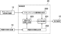
- the control device 20 of the nibbler heavy machine has a projection direction information generation unit 203.
- the projection direction information generation unit 203 automatically generates projection direction information based on the three-dimensional shape information and the attachment position information (step 5b shown in FIG. 9).
- the three-dimensional shape information is information generated by the surrounding shape information generation unit 202, information on the three-dimensional shape of the surrounding work area, and information including a three-dimensional shape corresponding to a building.
- the attachment position information is information generated by the attachment position information generation unit 200, and includes position information related to the position of at least the tip attachment (for example, the nibbler 54) of the attachment 50. A more detailed function of the projection direction information generation unit 203 will be described below.
- the control device 20 can determine whether an object is present near the tip attachment (nibra 54) based on the three-dimensional shape information (peripheral shape information) and the attachment position information. In the specific example shown in FIG. 6, the control device 20 determines that the wall surface 60b of the building exists near the nibler 54, and the shortest distance between the nibler 54 and the wall surface 60b of the building is X as shown in FIG. It is.
- the projection direction information generation unit 203 stores a reference point 54a of a tip attachment that is set in advance.
- the reference point 54a is set at the center of the nibler 54, for example, but is not limited thereto, and may be set at a position shifted from the center.
- the projection direction information generation unit 203 stores a plurality of preset directions.
- Each of the plurality of directions is a direction based on a predetermined specific part in a nibble heavy machine (construction machine) for building demolition.
- the specific part is set, for example, in any part of the main body of the nibbler heavy machine.
- Examples of the main body of the nibbler heavy machine include the upper swing body 3 or the lower traveling body 1.
- the plurality of directions include, for example, the front, rear, upper, and lower sides indicated by the four black arrows shown in FIG.
- the projection direction information generation unit 203 determines that the wall surface 60b of the building and the reference point 54a are in the plurality of directions (forward, backward, upward) with respect to the specific part. And the downward direction) are determined, and the direction as the determination result is automatically generated as projection direction information.
- the projection direction information is the front indicated by a white arrow in FIG.
- the projection direction information is generated not only when the projection direction information is forward as described above, but also based on the surrounding shape information and the attachment position information.
- the unit 203 can automatically generate appropriate projection direction information (projection direction information in an arbitrary direction).
- the attachment related information in this embodiment is calculated based on the shape information of the tip attachment 54, the attachment position information, and the three-dimensional shape information.
- the attachment-related information includes a surrounding image 60 that is an image corresponding to the three-dimensional shape of the surrounding work area, a projection image 70 obtained by projecting an image corresponding to the nibler 54 onto the surrounding image 60 in the projection direction, This is information corresponding to the image overlaid.
- the surrounding image 60 includes an image corresponding to a building existing in the surrounding work area.
- the projection direction is not only forward, but the projection direction information generation unit 203 automatically generates appropriate projection direction information based on the surrounding shape information and the attachment position information. Is possible.
- the attachment-related information is information corresponding to an image in which the projection image 70 of the tip attachment (nibler 54) is superimposed on the surrounding image 60 corresponding to the three-dimensional shape of the surrounding work area.
- the projection image 70 includes distance information calculated (generated) by the display control unit 201 of the control device 20.
- the distance information is information relating to the distance between the nibbler 54 and a portion corresponding to a portion where the surrounding image 60 and the projected image 70 overlap among objects existing in the surrounding work area.
- the projected image 70 is an image calculated (generated) by the display control unit 201, and is a projected image expressed in shades of color according to the distance information.
- the projected image 70 expressed by the color shading will be described in more detail with reference to FIG.
- the projection image 70 included in the image displayed on the screen of the display device 13 shown in FIG. 6 is a projection image expressed in the shades of the color, for example, a projection image expressed in the shades of black and white.
- the projection direction (projection direction indicated by a white arrow) may be set, for example, in a direction in which the nibler 54 approaches a part of the wall surface 6 b that is the target position of the building existing at the work site. .
- the projection image 70 is, for example, black and white according to distance information regarding the distance between the nibler 54 and a part corresponding to a portion of the building existing on the work site where the surrounding image 60 and the projection image 70 overlap. Expressed in shades. For example, the projected image 70 is expressed so that the color becomes darker as the distance between the building and the nibbler 54 becomes smaller, that is, as the two approach each other.
- the display control unit 201 displays a position for superimposing and displaying the projection image 70 on the surrounding image 60 based on the projection direction, the shape information of the attachment, the attachment position information, and the three-dimensional shape information. Calculate. Then, the display control unit 201 displays the projection image 70 on the surrounding image 60 on the display device 13 as shown in FIG.
- a tip attachment (book) to a target position (part of a wall surface) in a surrounding work area, specifically, for example, a building existing in a target work site.
- the nibbler 54 approach is more intuitively understood by the operator.
- the nibbler heavy machine according to the present embodiment has a guidance function that makes it easier for the operator to work.
- the tip attachment is the nibbler 54.
- the tip attachment may be various tip attachments other than the nibbler 54.
- the projection direction information generation unit 203 automatically generates the projection direction information related to the projection direction based on the surrounding shape information and the attachment position information.
- the projection direction information generation unit 203 automatically generates projection direction information for setting the movement direction of a specific part of the attachment 50, specifically, for example, the movement direction of the tip of the tip attachment as the projection direction. It may be configured.
- the attachment position information generation unit 200 generates attachment position information at a specific time point (for example, current) and attachment position information a predetermined time before the specific time point, and based on the attachment position information.
- the moving direction of the tip of the tip attachment (nibler 54) may be calculated, and projection direction information may be generated with the moving direction as the projection direction.
- the projection direction information generation unit 203 projects the projection direction information calculated a predetermined time before the specific time (for example, the present time). It may be generated as direction information.
- the specific part of the attachment 50 is not limited to the tip of the nibler 54, and is set, for example, at the tip of the bucket 6 shown in FIG. 1 or the tip of the arm 5 (for example, a position indicated by reference numeral 12c).
- the projection direction information generation unit 203 calculates the movement direction of the set specific part, and generates projection direction information with the movement direction as the projection direction.
- FIG. 3 10 is a side view showing a schematic configuration of a hydraulic excavator as a construction machine according to Embodiment 3 of the present invention
- FIG. 11 is a block diagram showing main functions of the hydraulic excavator shown in FIG.
- the surrounding shape detection apparatus 14 installed in the ceiling part of the cab 10 shown in FIG. 1 in the said Embodiment 1 is abbreviate
- the function performed by the surrounding shape detection device 14 is realized by the following three components shown in FIGS. 10 and 11 instead of the surrounding shape detection device 14.
- the first component is a storage device 17 that stores three-dimensional shape information (three-dimensional shape data of a construction site) of a surrounding work area prepared by photographing using a photographing device such as a drone in advance.
- the second component is a receiver 18 capable of receiving data related to a satellite positioning system such as GPS and GSNN, for example.
- the receiver 18 receives the data related to the satellite positioning system, thereby receiving the vehicle position information. Can be obtained.
- the third component is the upper swing body state detection device 16.
- the upper turning body state detection device 16 is installed in the turning mechanism 2, for example.
- the upper swing body state detection device 16 is configured by an orientation sensor for detecting the direction in which the upper swing body 3 faces, for example.
- the surrounding shape information generation unit 202 is detected by the three-dimensional shape data stored in the storage device 17, the vehicle position information acquired by the receiver 18, and the upper turning body state detection device 16. 3D shape information (peripheral shape information) of the surrounding work area is generated based on the information regarding the orientation of the upper swing body 3.
- the function performed by the surrounding shape detection device 14 illustrated in FIG. 1 is realized using the storage device 17, the receiver 18, and the upper swing body state detection device 16. It is not limited to these.
- the second component and the third component may be replaced by other components. Examples of such other components include a receiver capable of receiving data related to the satellite positioning system.
- the function of the surrounding shape detection device 14 shown in FIG. 1 is to use the three-dimensional shape information (three-dimensional shape data of the construction site) of the surrounding work area prepared by photographing using a photographing device such as a drone beforehand.
- a storage device 17 that stores data, a receiver 18 that can acquire vehicle position information by receiving data related to the satellite positioning system, and a direction of the upper turning body 3 by receiving data related to the satellite positioning system. And a receiver capable of acquiring information about the. That is, a plurality of receivers that can receive data related to the satellite positioning system can realize the functions of the second component and the third component.
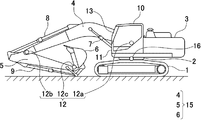
- FIG. 12 is a side view showing a schematic configuration of a hydraulic excavator as a construction machine according to Embodiment 4 of the present invention.
- the display device in the fourth embodiment is different from the display device 13 provided on the front side in the cab 10 shown in FIG. 1 in the first embodiment.
- the display device 110 according to the fourth embodiment includes a glasses-type transmissive head-mounted display (glasses-type transmissive HMD) worn by the operator 100 in the cab 10 shown in FIG.
- glasses-type transmissive head-mounted display glasses-type transmissive HMD
- the tip attachment buckle 6
- the hydraulic excavator according to the present embodiment has a guidance function that facilitates the operation for the operator.
- the hydraulic excavator according to the fourth embodiment also has an advantage that it is not necessary to install a large transmission type HUD like the display device 13 in the first embodiment on the front side in the cab 10.
- the transmissive HUD as the display device 13 described in the first to third embodiments and the glasses-type transmissive HMD as the display device 110 described in the fourth embodiment are both used in the cab 10.
- the display device is a premise, the display device according to the present invention is not necessarily present in the cab 10 and may be disposed outside the cab 10.
- the display device may be configured by a remote operation support monitor for an operator to remotely operate a hydraulic excavator (construction machine) outside the cab 10 using a remote operation device. Details of the remote operation support monitor will be described later in Embodiment 5 and Embodiment 6.
- the hydraulic excavator has a guidance function that makes it easy for the operator to work. And when an operator utilizes the said guidance function, it becomes unnecessary to move a viewpoint from the target work site, and the fall of work efficiency is suppressed.
- the remote operation support monitor when employed, the operator does not necessarily need to be at the actual work site, and remotely operates the construction machine in the building where the remote operation support monitor is set. It becomes possible. Thus, there is an effect that the degree of freedom of the place where the operator actually works is also increased.
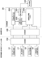
- FIG. 13 is a block diagram showing main functions of a hydraulic excavator as a construction machine according to Embodiment 5 of the present invention.
- the hydraulic excavator according to the fifth embodiment is different from the hydraulic excavator according to the third embodiment in that it has a configuration that can be remotely operated, and is otherwise the same as the hydraulic excavator according to the third embodiment. is there.
- the display device 120 is arranged not in the cab 10 of the excavator but in a remote place outside the cab 10.
- the hydraulic excavator according to the fifth embodiment includes a construction machine main body and a remote control unit.
- the construction machine main body includes the control device 20, the attachment state detection device 12, the storage device 17, the receiver 18, the upper swing body state detection device 16, and a transmission device 130.
- the remote control unit includes a display device 120 and a receiving device 140.
- the control device 20 and the display device 120 are mechanically separated.
- the control device 20 and the display device 120 are connected to each other via wireless communication.
- the display device 120 according to the fifth embodiment is a remote operation support monitor for an operator to remotely operate a hydraulic excavator (construction machine) outside the cab 10 using a remote operation device. . Therefore, this feature point will be described in detail below, and the same components as those in the third embodiment will be denoted by the same reference numerals and detailed description thereof will be omitted.
- the display device 120 in the hydraulic excavator is a remote operation support monitor for remotely operating the hydraulic excavator (construction machine) outside the cab 10.
- the transmission device 130 is provided in a construction machine main body (hydraulic excavator main body), and a signal output from the display control unit 201 is input to the transmission device 130.
- the receiving device 140 is provided in the remote control unit and receives a signal transmitted from the transmitting device 130. A signal received by the receiving device 140 is input to the display device 120.
- the display device 120 displays an image related to the input signal.
- the hydraulic excavator according to the fifth embodiment is configured such that information similar to the attachment-related information in the first embodiment is transmitted from the transmission device 130 to the reception device 140 by wireless communication.
- wireless communication include communication using radio waves, such as communication using a mobile phone network and communication using a wireless LAN.
- the attachment related information is generated in the construction machine main body of the hydraulic excavator.
- the attachment related information is generated based on the attachment position information and the three-dimensional shape information.
- the attachment-related information is an image (attachment-related image) obtained by superimposing a surrounding image that is an image corresponding to the three-dimensional shape of the surrounding work area and a projection image obtained by projecting an image corresponding to the tip attachment in the projection direction. ).
- the attachment related information is transmitted to the display device 120 (the remote operation support monitor) in the remote operation unit via the transmission device 130 and the reception device 140.
- the display device 120 (the remote operation support monitor) displays the received image. Therefore, it is possible to simplify the devices constituting the display device 120 (the remote operation support monitor).
- FIG. 14 is a block diagram showing main functions of a hydraulic excavator as a construction machine according to Embodiment 6 of the present invention.
- the hydraulic excavator according to the sixth embodiment is different from the hydraulic excavator according to the fifth embodiment in that the control device 20 is provided not in the construction machine body but in the remote control unit, and in other respects the fifth embodiment. It is the same as that of the hydraulic excavator concerning.
- the construction machine main body receives the vehicle position information by receiving data related to the attachment state detection device 12, the storage device 17 for storing the three-dimensional shape data of the construction site, and a satellite positioning system such as GPS.
- the receiver 18 which can be acquired, the upper turning body state detection apparatus 16, and the transmission apparatus 150 are included.
- the remote control unit includes a receiving device 160, the control device 20, and the display device 120.
- the attachment state detection device 12, the storage device 17, the receiver 18, the upper swing body state detection device 16, and the control device 20 are mechanically separated and connected to each other via wireless communication. It is characterized by that. Therefore, this feature point will be described in detail below, and the same components as those in the fifth embodiment will be denoted by the same reference numerals and detailed description thereof will be omitted.
- the transmission device 150 is provided in a construction machine main body (hydraulic excavator main body), and the transmission device 150 includes attachment basic data relating to the attachment state detected by the attachment state detection device 12, and Peripheral work area basic data serving as a basis for the three-dimensional shape information of the peripheral work area is input.
- the surrounding work area basic data is, for example, the construction site three-dimensional shape data stored in the storage device 17, the vehicle position information by the receiver 18, and the upper part detected by the upper turning body state detection device 16.
- the receiving device 160 is provided in the remote control unit, and receives the attachment basic data and the surrounding work area basic data transmitted from the transmitting device 150 via wireless communication.
- the attachment position information generation unit 200 generates attachment position information based on the attachment basic data received by the receiving device 160.
- the surrounding shape information generation unit 202 generates 3D shape information of the surrounding work area based on the surrounding work area basic data received by the receiving device 160.
- the display control unit 201 is configured to generate attachment-related information based on the attachment position information and the three-dimensional shape information, and to display the attachment-related information on the display device 120 (the remote operation support monitor). Is configured to do.
- the remote In the operation unit based on the attachment basic data and the surrounding work area basic data transmitted from the transmission device 150 provided in the construction machine main body (hydraulic excavator main body), the remote In the operation unit, the attachment related information is generated. Therefore, it is not necessary to mount a processing device for generating the image in a hydraulic excavator main body (construction machine main body) that generates more vibration and impact than the remote control unit. For this reason, the structure in a hydraulic shovel main body (construction machine main body) can be simplified.
- the attachment-related information projects a surrounding image that is an image corresponding to the three-dimensional shape of the surrounding work area and an image corresponding to the tip attachment in the projection direction with respect to the surrounding image.
- the information corresponding to the image superimposed with the projected image is not necessarily limited to this.
- the attachment related information according to the present invention may be information regarding an image obtained by projecting at least an image corresponding to the tip attachment to the surrounding image in the projection direction with respect to the surrounding image.
- the present inventors have earnestly studied how an approach of attachment to a target position in a surrounding work area (target work site) can realize a construction machine having an easy guidance function for an operator. Went. As a result, it has been found that the object can be achieved only by adopting various configurations as described below.
- the construction machine includes an attachment including a tip attachment.
- the construction machine includes an attachment state detection device that detects the state of the attachment, and attachment position information that generates attachment position information that is information regarding the position of the attachment based on the state of the attachment detected by the attachment state detection device.
- Attachment generated based on three-dimensional shape information which is information on the three-dimensional shape of the surrounding work area of the construction machine and the attachment position information generated by the generation unit, the display device, and the attachment position information generation unit
- a display control unit that performs control to display related information on the display device.
- the attachment-related information is a projection set based on a projection direction arbitrarily set or a predetermined condition of a surrounding image that is an image corresponding to the three-dimensional shape of the surrounding work area and an image corresponding to the tip attachment. This is information corresponding to an image obtained by superimposing a projection image projected on the surrounding image in the direction.
- the operator confirms the attachment related information displayed on the display device.
- an operation for bringing the tip attachment closer to the target position in the surrounding work area (target work site) can be performed. Therefore, according to the present invention, it is possible to provide a construction machine having a guidance function that makes it easy for the operator to approach the target work position in the surrounding work area.
- the display control unit can calculate a relative position of the tip attachment with respect to an object existing in the surrounding work area based on the attachment position information and the three-dimensional shape information.
- the display control unit may generate the surrounding image based on the three-dimensional shape information, and based on the relative position, an image corresponding to the tip attachment may be projected in the projection direction with respect to the surrounding image. Therefore, the display control unit can generate an image (superimposed image) obtained by superimposing the surrounding image and the projection image. Therefore, the display control unit can generate the attachment related information based on the attachment position information and the three-dimensional shape information, and can perform control to display the attachment related information on the display device. it can.
- the projection image is a color corresponding to distance information related to a distance between the tip attachment and a portion corresponding to a portion where the surrounding image and the projection image overlap among objects existing in the surrounding work area. It is preferable that the color is expressed by the shade or color type.
- the projected image is expressed by color shades or color types according to the distance information. This makes it easy for the operator to intuitively recognize the distance information based on the color shade or the color type.
- the display control unit can calculate the relative position of the tip attachment with respect to the object existing in the surrounding work area based on the attachment position information and the three-dimensional shape information. . Further, the display control unit can calculate a distance between the tip attachment and the part of the object based on the relative position. Therefore, the display control unit can generate the projection image represented by color shades or color types according to the distance information based on the attachment position information and the three-dimensional shape information.
- the construction machine includes a surrounding shape detection device that detects the three-dimensional shape of the surrounding work area, and the surrounding work area based on the three-dimensional shape of the surrounding work area detected by the surrounding shape detection device. It is preferable to further include a surrounding shape information generation unit that generates three-dimensional shape information.
- the surrounding shape information generation unit since the surrounding shape information generation unit generates the three-dimensional shape information based on the three-dimensional shape of the surrounding work area detected by the surrounding shape detection device, the construction machine can perform the target work. It is not necessary to store the three-dimensional shape information of the surrounding work area at the site as data before starting the work.
- the surrounding shape detection device may be configured to detect the shape of the tip attachment.
- the construction machine is detected by the surrounding shape detection device. Based on the shape of the second tip attachment, the shape information of the second tip attachment can be acquired. This enables the shape information of the tip attachment to be updated to the latest information even when the tip attachment is replaced.
- the surrounding shape detection device since the surrounding shape detection device has a function of detecting the three-dimensional shape of the surrounding work area and a function of detecting the shape of the tip attachment, the configuration of the construction machine is complicated. Can be suppressed.
- the attachment state detection device may be configured to detect the three-dimensional shape of the surrounding work area.
- the attachment state detection device since the attachment state detection device has a function of detecting the state of the attachment and a function of detecting the three-dimensional shape of the surrounding work area, the three-dimensional shape of the surrounding work area is detected.
- a device for performing the above for example, the surrounding shape detection device as described above
- the display device may be a transmissive head-up display provided on the front side in the cab.
- the display device is a transmissive head-up display
- an area for displaying the attachment-related information can be set relatively freely compared to the case where the display device is a liquid crystal display, for example. It can suppress that an operator's visual field is obstruct
- the display device may be a transmissive head mounted display configured to be worn by an operator in a cab.
- the display device is a head-mounted display, it is possible to prevent the field of view of the operator from being blocked as compared with a case where the display device is a liquid crystal display, for example.
- the head mounted display is a transmission type, the visual information obtained by the operator is not limited to the information displayed on the head mounted display, and the visual information of the operator is transmitted through the head mounted display. Information that acts is also included. Therefore, the operator can perform, for example, a switch operation for operating a switch in the cab without being obstructed by the head mounted display.
- the construction machine includes a transmission device provided in a construction machine main body including the attachment, and a reception device provided in a remote operation unit for remotely operating the construction machine main body outside a cab of the construction machine main body.
- the display device is a remote operation support monitor provided in the remote operation unit, and a signal related to the attachment-related information output from the display control unit is wirelessly transmitted from the transmission device to the reception device.
- the remote operation support monitor may be configured to display the attachment related information based on the signal transmitted by communication and received by the receiving device.
- the operator does not necessarily have to go to the actual work site, and can remotely operate the construction machine at the remote operation unit provided in a remote place away from the work site.
- the construction machine is a transmission device provided in a construction machine main body including the attachment, the attachment basic data regarding the state of the attachment detected by the attachment state detection device, and the three-dimensional shape information of the surrounding work area
- the attachment basic data and the surrounding work area basic data transmitted from the transmission device are received by wireless communication, and the remote operation unit is provided with the surrounding work area basic data received by the receiving device.
- the display device Surrounding shape information for generating the 3D shape information of the surrounding work area based on
- the display device is a remote operation support monitor provided in the remote operation unit, and the attachment position information generation unit is provided in the remote operation unit and is received by the reception device.
- the attachment control unit generates attachment position information based on the attached attachment basic data
- the display control unit is provided in the remote operation unit, and is configured to perform control to display the attachment related information on the remote operation support monitor May be.
- the operator does not necessarily have to go to the actual work site, and can remotely operate the construction machine at the remote control unit provided in a remote place away from the work site.
- the attachment position information generation unit and the surrounding shape information generation unit are provided in the remote operation unit, the attachment position information and the three-dimensional shape information are generated in the remote operation unit. . That is, in this aspect, it is not necessary to mount the processing devices that constitute the attachment position information generation unit and the surrounding shape information generation unit on a construction machine main body that generates a lot of vibration and impact.
Landscapes
- Engineering & Computer Science (AREA)
- Mining & Mineral Resources (AREA)
- Civil Engineering (AREA)
- General Engineering & Computer Science (AREA)
- Structural Engineering (AREA)
- Physics & Mathematics (AREA)
- General Physics & Mathematics (AREA)
- Optics & Photonics (AREA)
- Component Parts Of Construction Machinery (AREA)
- Closed-Circuit Television Systems (AREA)
Abstract
建設機械は、アタッチメント位置情報生成部により生成されるアタッチメント位置情報と前記建設機械の周囲作業エリアの三次元形状情報とに基づいて生成されるアタッチメント関連情報を表示装置に表示させる制御を行う表示制御部を備え、前記アタッチメント関連情報は、前記周囲作業エリアの三次元形状に対応する像である周囲像(30)と、先端アタッチメント(6)に対応する像を任意に設定される投影方向又は所定の条件に基づいて設定される投影方向に前記周囲像(30)に対して投影した投影像(40)と、を重ねた画像に対応する情報である。
Description
本発明は、建設機械に関する。
建設機械が位置する平面(基準位置)とアタッチメント先端との距離情報を数字で、アタッチメントとともに、建設機械の運転室内に搭載された表示装置に表示する技術が知られている(例えば、特許文献1参照)。
また、建設機械の運転室内の前側に設けられた透過型の表示装置に、オペレータが作業をするのに必要な情報をアタッチメントとともに表示させる技術が知られている(例えば、特許文献2参照)。具体的には、当該特許文献2は、前記表示装置において、前記必要な情報を先端アタッチメントの横に、文字による表示または色を含む表示として重畳させて表示する技術を開示している。
しかし、上記特許文献1に開示された技術では、距離情報が数字だけで表示されるため、オペレータが作業状況を直感的に把握し難く、また、凹凸や斜面のある周囲作業エリア(現場)における作業に対応し難いという問題点を有する。
また、上記特許文献2に開示された技術は、作業に必要な情報が先端アタッチメントの横に、文字による表示または色を含む表示として重畳して表示されるだけであるため、オペレータへ作業をガイダンスするためのガイダンス機能が不十分である。
本発明の目的は、周囲作業エリア(対象とする作業現場)の目標位置へのアタッチメントのアプローチがオペレータにとって容易になるガイダンス機能を有する建設機械を提供することにある。
提供されるのは、先端アタッチメントを含むアタッチメントを備える建設機械であって、前記アタッチメントの状態を検出するアタッチメント状態検出装置と、前記アタッチメント状態検出装置により検出される前記アタッチメントの状態に基づいてアタッチメントの位置に関する情報であるアタッチメント位置情報を生成するアタッチメント位置情報生成部と、表示装置と、前記アタッチメント位置情報生成部により生成される前記アタッチメント位置情報と前記建設機械の周囲作業エリアの三次元形状に関する情報である三次元形状情報とに基づいて生成されるアタッチメント関連情報を前記表示装置に表示させる制御を行う表示制御部と、を備える。前記アタッチメント関連情報は、前記周囲作業エリアの前記三次元形状に対応する像である周囲像と、前記先端アタッチメントに対応する像を任意に設定される投影方向又は所定の条件に基づいて設定される投影方向に前記周囲像に対して投影した投影像と、を重ねた画像に対応する情報である。
以下、図面を参照しつつ、本発明の実施形態について説明する。なお、本発明の実施形態を説明するための全図において、同一の機能を有する部分には同一又は関連する符号を付し、その繰返しの説明は省略する。また、以下の実施形態では、特に必要なとき以外は同一又は同様な部分の説明を原則として繰返さない。
(実施形態1)
図1は、本発明の実施形態1に係る建設機械としての油圧ショベルの概略構成を示す側面図である。図2は、図1に示す油圧ショベルのアタッチメント15を投影する方向を説明するための説明図である。図3は、図1に示す油圧ショベルの主要機能を示すブロック図である。図4は、図1に示すアタッチメント15のうちの先端アタッチメントとしてのバケット6の投影像を周囲像に重畳して表示させる制御処理の流れを示すフローチャートである。図5は、前記油圧ショベルにおける表示装置の画面に、先端アタッチメントとしてのバケットの投影像を色の濃淡で表現した例を示す図である。
図1は、本発明の実施形態1に係る建設機械としての油圧ショベルの概略構成を示す側面図である。図2は、図1に示す油圧ショベルのアタッチメント15を投影する方向を説明するための説明図である。図3は、図1に示す油圧ショベルの主要機能を示すブロック図である。図4は、図1に示すアタッチメント15のうちの先端アタッチメントとしてのバケット6の投影像を周囲像に重畳して表示させる制御処理の流れを示すフローチャートである。図5は、前記油圧ショベルにおける表示装置の画面に、先端アタッチメントとしてのバケットの投影像を色の濃淡で表現した例を示す図である。
図1に示すように、油圧ショベルは、下部走行体1と、当該下部走行体1に対して旋回可能に搭載される上部旋回体3と、当該上部旋回体3に装着されるアタッチメント15と、を備える。前記上部旋回体3は、旋回機構2を介して前記下部走行体1に搭載される。前記アタッチメント15は、ブーム4と、アーム5と、バケット6(先端アタッチメントの一例)と、を含む。前記ブーム4は前記上部旋回体3に取り付けられ、前記アーム5はブーム4の先端に取り付けられ、前記バケット6はアーム5の先端に取り付けられる。ブーム4、アーム5、及びバケット6は、ブームシリンダ7、アームシリンダ8、及びバケットシリンダ9によりそれぞれ油圧駆動される。また、上部旋回体3には、運転室10が設けられ、且つエンジン等の動力源が搭載される。
前記油圧ショベルは、アタッチメント15の状態を検出するアタッチメント状態検出装置12をさらに備える(図4に示すステップS1)。当該アタッチメント状態検出装置12は、例えばアタッチメント15、上部旋回体3などに搭載される。
前記アタッチメント状態検出装置12は、例えば、油圧ショベルのアタッチメント15の状態に関する情報を取得するためのセンサである。本実施形態では、アタッチメント状態検出装置12は、上部旋回体3に対するブーム4の傾きを検出するブーム角度センサ12aと、ブーム4に対するアーム5の傾きを検出するアーム角度センサ12bと、アーム5に対するバケット6の傾きを検出するバケット角度センサ12cと、を含む。なお、本実施形態においては、アタッチメント状態検出装置12は、上記の角度センサを含むが、必ずしもこのような構成に限定されるものではない。前記アタッチメント状態検出装置12は、例えば、下記の6通りの構成のうちの少なくとも一つで代用することも可能である。下記6通りの構成は、組合せる機器の数が多くなる程、アタッチメント15の状態に関する情報を検出する精度が向上する。
1.対象物(アタッチメント)までの距離とともに三次元画像を取得できる深度センサ
2.前記深度センサとバケット6の先端に設置したジャイロセンサとの組合せ
3.前記深度センサと前記ジャイロセンサとバケット6の先端に配置したARマーカー(AR:Augmented Reality)との組み合わせ(前記ARマーカー:ARシステムにおいて、付加情報を表示する位置を指定するための標識となる決まったパターンの画像)
4.ステレオカメラ
5.前記ステレオカメラと前記ジャイロセンサとの組合せ
6.前記ステレオカメラと前記ジャイロセンサと前記ARマーカーとの組合せ
1.対象物(アタッチメント)までの距離とともに三次元画像を取得できる深度センサ
2.前記深度センサとバケット6の先端に設置したジャイロセンサとの組合せ
3.前記深度センサと前記ジャイロセンサとバケット6の先端に配置したARマーカー(AR:Augmented Reality)との組み合わせ(前記ARマーカー:ARシステムにおいて、付加情報を表示する位置を指定するための標識となる決まったパターンの画像)
4.ステレオカメラ
5.前記ステレオカメラと前記ジャイロセンサとの組合せ
6.前記ステレオカメラと前記ジャイロセンサと前記ARマーカーとの組合せ
また、図1及び図3に示すように、前記油圧ショベルは、制御装置20と、表示装置13と、周囲形状検出装置14と、をさらに備える。前記制御装置20及び表示装置13は、例えば運転室10の内部に設置される。また、前記周囲形状検出装置14は、例えば運転室10の天井部に設置される。
前記周囲形状検出装置14は、油圧ショベルの前方の周囲作業エリアの三次元形状を検出することが可能な装置である(例えば、図4に示すステップS3)。当該周囲作業エリアは、建設機械の周囲に位置する作業対象(作業現場)である。前記三次元形状は、以下では「周囲形状」とも称される。
前記表示装置13としては、例えば、透過型ヘッドアップディスプレイ(以下、「透過型HUD」とも称される)を挙げることができる。当該透過型HUDは、例えば運転室10の前面に配置されたフロントガラス11の内側(「運転室10内の前側」とも称される)に設けられる。表示装置13の一例である透過型HUDは、必ずしもフロントガラス11と別体である必要はなく、前記フロントガラス11と一体であってもよい。また、前記表示装置13は、前記透過型HUD以外の他のディスプレイであってもよい。
また、周囲形状検出装置14としては、例えば、画素毎に距離情報を有する距離画像を取得することが可能な距離画像センサ(距離画像カメラ)を挙げることができる。当該距離画像センサとしては、例えば、近赤外線LEDの高速光源とCMOSイメージセンサから構成された周囲作業エリアの三次元形状を検出可能なTOF方式三次元距離画像センサ(例えば、オプテックス社製)を挙げることができる(TOF:Time of Flight)。前記周囲形状検出装置14は、前記距離画像センサ以外の装置であってもよい。
図3に示す主要機能ブロックは、アタッチメント状態検出装置12、表示装置13、周囲形状検出装置14、投影方向指示入力装置19及び制御装置20で構成される。
前記投影方向指示入力装置19は、オペレータによる入力を受ける入力機能を有する。具体的には、例えば、投影方向指示入力装置19は、タッチパネルを有する。当該タッチパネルの表示画面は、例えば、図2に示すように、油圧ショベルの側面と、油圧ショベルのアタッチメント15を投影する方向(以下、「投影方向」と称される。)を示す複数の矢印、具体的には例えば8つの矢印と、が重ねて表示されている。したがって、オペレータは、この表示画面上に表示された前記複数の矢印のうちの何れかの矢印を選択的に指定する(クリック又はタッチする)ことにより、希望する投影方向を入力することができる。前記制御装置20は、図4に示すステップS5aに示すように、オペレータにより入力された前記投影方向に関する入力情報に基づいて、投影方向情報を生成する。
なお、本実施形態においては、投影方向指示入力装置19は、前記表示装置13とは別の装置として独立して設けられているが、必ずしもこれに限定されるものではない。例えば、表示装置13の表示画面がタッチパネルにより構成されている場合には、当該表示装置13は、前記投影方向指示入力装置19が有する入力機能を備えたものであってもよく、かかる場合には、前記投影方向指示入力装置19は省略可能である。また、本実施形態においては、投影方向がオペレータによって手動で選択的に入力され、入力された前記投影方向に関する入力情報に基づいて前記制御装置20が投影方向情報を生成するが、必ずしもこれに限定されるものではない。例えば、後述する実施形態2のように、オペレータによる入力が省略され、前記制御装置20が投影方向情報を自動で生成することも可能である。
制御装置20は、例えば、CPU、RAM、ROM等を備えるコンピュータである。具体的には、制御装置20は、アタッチメント位置情報生成部200と、表示制御部201と、周囲形状情報生成部202と、を機能として備える。
前記アタッチメント位置情報生成部200は、図4に示すステップS2に示すように、前記アタッチメント状態検出装置12により検出されるアタッチメント15の状態に基づいて、アタッチメント15の位置に関する情報(アタッチメント位置情報)を生成する。
具体的には、前記アタッチメント状態検出装置12がブーム角度センサ12a、アーム角度センサ12b及びバケット角度センサ12cを含む場合には、前記アタッチメント位置情報生成部200は、これらのセンサ12a,12b,12cにより検出される信号に基づいて、前記アタッチメント15の姿勢を演算することができ、従って、前記アタッチメント位置情報生成部200は、先端アタッチメント(バケット6)の位置を演算することができる。
前記周囲形状情報生成部202は、図4に示すステップS4に示すように、前記周囲形状検出装置14により検出される周囲作業エリアの三次元形状(周囲形状)に基づいて周囲作業エリアの三次元形状情報(周囲形状情報)を生成する。具体的には、前記周囲形状情報生成部202は、上部旋回体3に設けられた周囲形状検出装置14と、周囲エリアに存在する複数の物体との相対位置(座標)を演算することができる。前記複数の物体としては、例えば地盤、ビル、他の車両、作業員などを挙げることができる。前記油圧ショベルが前記周囲形状検出装置14及び前記周囲形状情報生成部202を備えることにより、前記制御装置20が前記周囲形状情報を予めデータとして記憶していなくても、前記周囲形状情報を取得することが可能なシステムが提供される。
前記表示制御部201は、アタッチメント位置情報生成部200により生成される前記アタッチメント位置情報と、周囲形状検出装置14により検出される前記周囲形状情報とに基づいて、アタッチメント関連情報を生成し、当該アタッチメント関連情報を表示装置13に表示させる制御を行う(図4に示すステップS9)。
アタッチメント位置情報生成部200、表示制御部201及び周囲形状情報生成部202の各機能要素に対応するプログラムは、ROMから読み出されてRAMにロードされ、各機能要素に対応する処理をCPUが実行する。
前記アタッチメント関連情報は、前記周囲作業エリアの前記三次元形状に対応する像である周囲像と、前記先端アタッチメントに対応する像を後述する投影方向に前記周囲像に対して投影した投影像と、を重ねた画像に対応する情報である。
前記表示制御部201は、前記アタッチメント位置情報生成部200により演算される前記先端アタッチメントの位置(座標)と、前記周囲形状情報生成部202により演算される周囲形状検出装置14と周囲エリアに存在する複数の物体との相対位置(座標)と、に基づいて、前記先端アタッチメントの位置と周囲エリアに存在する複数の物体との相対位置(座標)を演算することができる。また、前記表示制御部201は、前記三次元形状情報に基づいて前記周囲像を生成することができ、前記アタッチメント位置情報と前記三次元形状情報とに基づいて前記投影像を生成することができる。従って、前記表示制御部201は、前記アタッチメント位置情報と前記三次元形状情報とに基づいて、前記アタッチメント関連情報を生成することができる。なお、前記表示制御部201は、前記先端アタッチメントの形状に関する情報である形状情報に基づいて、前記先端アタッチメントに対応する像を生成する。前記先端アタッチメントの前記形状情報は、制御装置20の記憶部に予め記憶されている。
従って、本実施形態では、前記アタッチメント関連情報は、先端アタッチメントの形状情報と、前記アタッチメント位置情報と、前記三次元形状情報と、に基づいて演算される。
前記投影方向は、任意に設定される方向(任意方向)、又は所定の条件に基づいて設定される方向である。前記任意方向は、三次元空間における種々の方向のうちから、オペレータによって任意に設定される方向である。具体的に、当該任意方向は、例えば、図2に示す複数の矢印(具体的には例えば8つの矢印)により示される複数の方向のうちからオペレータにより任意に選択されて設定される方向である。前記所定の条件に基づいて設定される方向は、例えば、前記制御装置20が前記所定の条件に基づいて設定する方向である。前記所定の条件は、例えば、予め設定されて前記制御装置20に記憶されたものであってもよく、油圧ショベルによる作業前や作業中においてオペレータや種々のセンサなどから制御装置20に入力される情報に基づいて設定されて前記制御装置20に記憶されたものであってもよい。
上記のように、前記周囲像に前記投影像を重ねた画像に対応する前記アタッチメント関連情報が前記表示装置13に表示されるという構成が採用されることにより、周囲作業エリア、具体的には、作業対象とされる作業現場であって起伏のある土地において、目標位置への先端アタッチメント(例えば、バケット6)のアプローチが、オペレータにより直感的に把握され易くなる。このように本実施形態に係る油圧ショベルは、オペレータにとって作業が容易になるガイダンス機能を有する。
上述したように、前記アタッチメント関連情報は、前記先端アタッチメント(バケット6)の投影像が前記周囲作業エリアの三次元形状に対応する周囲像に重畳された画像に対応する情報である。この投影像は、制御装置20の表示制御部201により演算(生成)される距離情報を含む。上述したように、前記表示制御部201は、前記先端アタッチメントの位置と周囲エリアに存在する複数の物体との相対位置(座標)を演算することができる。従って、前記表示制御部201は、演算された前記相対位置に基づいて前記距離情報を生成することができる。当該距離情報は、前記バケット6と、前記周囲作業エリアに存在する物体のうち前記周囲像と投影像とが重なる部分に対応する部位との距離に関する情報である(図4に示すステップS6)。
前記投影像は、表示制御部201で演算(生成)された像であって、前記距離情報に応じて色の濃淡で表現された投影像である(図4に示すステップS7)。
前記色の濃淡で表現された投影像については、図5を用いてさらに詳細に説明する。図5に示す前記表示装置13の画面に表示される画像は、周囲作業エリアである作業現場(例えば、起伏のある土地)の三次元形状に対応する像である周囲像30と、前記色の濃淡(例えば白黒の濃淡)で表現された投影像40と、バケット6の画像と、を含む。図5において、矢印で示す投影方向は、例えば、作業現場(起伏のある土地)の目標位置の一例である地面にバケット6がアプローチする方向に設定されている。
前記投影像40は、バケット6と、作業現場の地面のうち前記周囲像30と投影像40とが重なる部分に対応する部位との間の距離に関する距離情報に応じて、例えば白黒の濃淡で表現される。例えば、前記投影像40は、前記地面と前記バケット6との距離が小さくなる程、すなわち、両者が接近する程、色が濃くなるように表現される。
前記表示制御部201は、前記投影方向、前記先端アタッチメントの形状情報、前記アタッチメント位置情報、及び前記三次元形状情報に基づいて、投影像40を周囲像30に重畳させて表示するための位置を演算する(図4に示すステップS8)。そして、前記表示制御部201は、図5に示すように表示装置13において前記周囲像30に前記投影像40を重ねて表示する(図4に示すステップS9)。
上述した本実施形態に係る構成が採用されることにより、周囲作業エリア、具体的には、例えば対象とする作業現場であって起伏のある土地において、目標位置への先端アタッチメント(本実施形態ではバケット6)のアプローチが、オペレータによってより直感的に把握され易くなる。このように本実施形態に係る油圧ショベルは、オペレータにとって作業がさらに容易になるガイダンス機能を有する。また、作業現場において、建設機械(本実施形態では油圧ショベル)に対して、斜め上方で且つ前方の方向や上方に構造物や電線(物体の一例)が存在する場合がある。このような場合にも、前記構造物や電線と油圧ショベルのアタッチメント15との間の距離情報が、表示装置13に表示されてもよい。この場合、オペレータは前記先端アタッチメントと前記物体との間の距離を容易に認識することができ、建設機械(油圧ショベル)と前記構造物や電線との接触を回避しやすくなる。これにより、オペレータの目視による負担も小さくなる。
本実施形態においては、投影像40は、前記距離情報に応じて白黒の濃淡で表現され、両者が接近する程、色が濃くなるように表現されるが、必ずしもこれに限定されるものではない。例えば、前記投影像40は、白黒以外の別の色の濃淡で表現され、両者が接近する程、色が濃くなるように表現されてもよい。また、当該投影像40は、両者の接近の程度に応じて設定された複数の種類の色で表現されてもよい。この他にも、前記投影像40は、両者の接近の程度を識別可能な標識により表現されてもよい。
また、本実施形態においては、表示装置13として、運転室10内の前側に設けられた透過型HUDが採用されているため、オペレータは、前記ガイダンス機能を活用する際に、対象とする作業現場から視線(視点)を移動する必要がなくなる。このことは、作業効率の低下を抑制することを可能にする。また、本実施形態においては、周囲形状検出装置14として、周囲作業エリアの三次元形状を検出可能なTOF方式三次元距離画像センサが採用されているため、周囲形状検出装置14は、周囲作業エリアの三次元形状とともにアタッチメントの位置も同時に検出することが可能である。したがって、本実施形態では、前記アタッチメント位置情報生成部200は、前記周囲形状検出装置14により検出される前記アタッチメントの位置に関する情報に基づいて、前記アタッチメント位置情報を生成することも可能である。このような場合には、前記周囲形状検出装置14は、アタッチメント状態検出装置としての機能を兼ね備える。すなわち、前記周囲形状検出装置14により構成されるアタッチメント状態検出装置は、前記アタッチメントの状態を検出する機能と、前記周囲作業エリアの前記三次元形状を検出する機能とを併せ持つ。かかる場合、図1に示す前記アタッチメント状態検出装置12を省略できる。
(実施形態2)
図6は、本発明の実施形態2に係る建設機械としてのビル解体用ニブラ重機における表示装置の画面において、先端アタッチメントとしてのニブラの投影像を色の濃淡で表現した例を示す図である。図7は、図6におけるA部を拡大した説明図である。図8は、図6に示すニブラ重機の主要機能を示すブロック図である。図9は、先端アタッチメント(ニブラ)の投影像を周囲像に重畳して表示させる制御処理の流れを示すフローチャートである。
図6は、本発明の実施形態2に係る建設機械としてのビル解体用ニブラ重機における表示装置の画面において、先端アタッチメントとしてのニブラの投影像を色の濃淡で表現した例を示す図である。図7は、図6におけるA部を拡大した説明図である。図8は、図6に示すニブラ重機の主要機能を示すブロック図である。図9は、先端アタッチメント(ニブラ)の投影像を周囲像に重畳して表示させる制御処理の流れを示すフローチャートである。
図6に示すように、前記ニブラ重機は、下部走行体1と、上部旋回体3と、当該上部旋回体3に装着されるアタッチメント50と、を備える。当該アタッチメント50は、ブーム51と、第1アーム52と、第2アーム53と、ニブラ54(先端アタッチメントの一例)と、を含む。
前記ニブラ重機は、アタッチメント50の状態を検出するアタッチメント状態検出装置55をさらに備える。当該アタッチメント状態検出装置55は、例えばアタッチメント50に搭載される。当該ニブラ重機におけるアタッチメント状態検出装置55は、図1~図3に示すアタッチメント状態検出装置12と同一の機能を有する。
前記アタッチメント状態検出装置55は、例えば、ビル解体用ニブラ重機のアタッチメント50の状態に関する情報を取得するためのセンサである。本実施形態では、アタッチメント状態検出装置55は、上部旋回体3に対するブーム51の傾きを検出するブーム角度センサ55aと、ブーム51に対する第1アーム52の傾きを検出する第1アーム角度センサ55bと、第1アーム52に対する第2アーム53の傾きを検出する第2アーム角度センサ55cと、第2アーム53に対するニブラ54の傾きを検出するニブラ角度センサ55dと、を含む。
前記表示装置13の画面に表示される画像は、図6において破線Lで囲まれた領域の画像であり、当該領域の三次元形状に対応する像である周囲像60と、投影像70と、ニブラ54の画像と、を含む。前記周囲像60は、周囲作業エリアの三次元形状に対応する像であり、本実施形態では、作業対象とされる作業現場に建設されたビル(物体の一例)に対応する画像を含む。図6において、ビル解体用ニブラ重機は、地盤90の上に配置され、前記ビルは、前記地盤90に建てられている。
図8に示すように、前記ニブラ重機の制御装置20は、投影方向情報生成部203を有する。この投影方向情報生成部203は、前記三次元形状情報と前記アタッチメント位置情報とに基づいて投影方向情報を自動的に生成する(図9に示すステップ5b)。前記三次元形状情報は、周囲形状情報生成部202が生成する情報であり、前記周囲作業エリアの三次元形状に関する情報であり、ビルに対応する三次元形状を含む情報である。前記アタッチメント位置情報は、アタッチメント位置情報生成部200が生成する情報であり、前記アタッチメント50のうちの少なくとも先端アタッチメント(例えば、ニブラ54)の位置に関するする位置情報を含む。前記投影方向情報生成部203のより詳細な機能について、以下に説明する。
前記制御装置20は、前記三次元形状情報(周囲形状情報)と前記アタッチメント位置情報とに基づいて、先端アタッチメント(ニブラ54)の近くに物体が存在するか否かを判定することができる。図6に示す具体例では、前記制御装置20は、ニブラ54の近くにビルの壁面60bが存在することを判定し、図7に示すようにニブラ54とビルの壁面60bとの最短距離はXである。
投影方向情報生成部203は、予め設定された先端アタッチメントの基準点54aを記憶している。本実施形態では、前記基準点54aは、例えばニブラ54の中心に設定されているが、これに限られず、前記中心からずれた位置に設定されてもよい。
前記投影方向情報生成部203は、予め設定された複数の方向を記憶している。当該複数の方向のそれぞれは、ビル解体用ニブラ重機(建設機械)における予め設定された特定部位を基準とする方向である。当該特定部位は、例えばニブラ重機の本体のうちの何れかの部位に設定される。当該ニブラ重機の本体としては、例えば上部旋回体3又は下部走行体1が挙げられる。本実施形態では、当該複数の方向は、例えば、図6に示す黒色の4つの矢印により示される前方、後方、上方及び下方を含む。前記投影方向情報生成部203は、前記アタッチメント位置情報及び前記三次元形状情報に基づいて、前記ビルの壁面60b及び前記基準点54aが前記特定部位に対して前記複数の方向(前方、後方、上方及び下方)のうちのどの方向に位置しているかを判定し、その判定結果としての方向を投影方向情報として自動的に生成する。図6及び図7に示す本実施形態の場合には、前記投影方向情報は、図6において白色の矢印で示される前方である。また、本実施形態に係る構成が採用される場合には、前記投影方向情報が上記のように前方である場合だけでなく、前記周囲形状情報と前記アタッチメント位置情報に基づいて、投影方向情報生成部203は、適切な投影方向情報(任意方向の投影方向情報)を自動的に生成することが可能である。
本実施形態におけるアタッチメント関連情報は、先端アタッチメント54の形状情報と、前記アタッチメント位置情報と、前記三次元形状情報と、に基づいて演算される。当該アタッチメント関連情報は、前記周囲作業エリアの三次元形状に対応する像である周囲像60と、ニブラ54に対応する像を前記投影方向に前記周囲像60に対して投影した投影像70と、を重ねた画像に対応する情報である。前記周囲像60は、前記周囲作業エリアに存在するビルに対応する画像を含む。本実施形態では、前記投影方向は、上記前方である場合だけでなく、投影方向情報生成部203が前記周囲形状情報と前記アタッチメント位置情報に基づいて適切な投影方向情報を自動的に生成することが可能である。
前記アタッチメント関連情報は、前記先端アタッチメント(ニブラ54)の投影像70が前記周囲作業エリアの三次元形状に対応する周囲像60に重畳された画像に対応する情報である。この投影像70は、制御装置20の表示制御部201により演算(生成)される距離情報を含む。当該距離情報は、前記ニブラ54と、前記周囲作業エリアに存在する物体のうち前記周囲像60と前記投影像70とが重なる部分に対応する部位との間の距離に関する情報である。
前記投影像70は、表示制御部201で演算(生成)された像であって、前記距離情報に応じて色の濃淡で表現された投影像である。
前記色の濃淡で表現された投影像70については、図6を用いてさらに詳細に説明する。図6に示す表示装置13の画面に表示される画像に含まれる投影像70は、前記色の濃淡で表現された投影像であり、例えば、白黒の濃淡で表現された投影像である。図6において、投影方向(白色の矢印で示す投影方向)は、例えば、作業現場に存在するビルの目標位置である壁面6bの一部に対してニブラ54がアプローチする方向に設定されてもよい。
前記投影像70は、ニブラ54と、作業現場に存在するビルのうち前記周囲像60と前記投影像70とが重なる部分に対応する部位との間の距離に関する距離情報に応じて、例えば白黒の濃淡で表現される。例えば、前記投影像70は、前記ビルと前記ニブラ54との距離が小さくなる程、すなわち、両者が接近する程、色が濃くなるように表現される。
前記表示制御部201は、前記投影方向、前記アタッチメントの形状情報、前記アタッチメント位置情報、及び前記三次元形状情報に基づいて、投影像70を前記周囲像60に重畳させて表示するための位置を演算する。そして、前記表示制御部201は、図6に示すように表示装置13において前記周囲像60に前記投影像70を重ねて表示する。
上述した本実施形態に係る構成が採用されることにより、周囲作業エリア、具体的には、例えば対象とする作業現場に存在するビルにおいて、目標位置(壁面の一部)への先端アタッチメント(本実施形態ではニブラ54)のアプローチが、オペレータによってより直感的に把握され易くなる。このように本実施形態に係るニブラ重機は、オペレータにとって作業がさらに容易になるガイダンス機能を有する。なお、本実施形態においては、先端アタッチメントがニブラ54であるが、本発明では、先端アタッチメントは、前記ニブラ54以外のさまざまな先端アタッチメントであってもよい。
本実施形態においては、前記周囲形状情報と前記アタッチメント位置情報に基づき、投影方向情報生成部203が前記投影方向に係る投影方向情報を自動的に生成するが、これに限定されるものではない。例えば、投影方向情報生成部203は、アタッチメント50のうちの特定部位の移動方向、具体的には例えば先端アタッチメントの先端の移動方向を投影方向に設定する投影方向情報を自動的に生成するように構成されていてもよい。具体的には、アタッチメント位置情報生成部200は、特定時点(例えば現在)のアタッチメント位置情報と、前記特定時点よりも所定時間前のアタッチメント位置情報とを生成し、これらのアタッチメント位置情報に基づいて、先端アタッチメント(ニブラ54)の先端の移動方向を演算し、この移動方向を前記投影方向とする投影方向情報を生成するように構成されていてもよい。また、先端アタッチメント(ニブラ54)の先端の動作が停止している場合には、前記投影方向情報生成部203は、特定時点(例えば現在)よりも所定時間前に演算した投影方向情報を、投影方向情報として生成してもよい。また、アタッチメント50の特定部位は、ニブラ54の先端に限定されるものではなく、例えば、図1に示すバケット6の爪先やアーム5の先端(例えば符号12cにより示される位置)に設定されていてもよく、前記投影方向情報生成部203は、設定された特定部位の移動方向を演算し、この移動方向を前記投影方向とする投影方向情報を生成する。
(実施形態3)
図10は、本発明の実施形態3に係る建設機械としての油圧ショベルの概略構成を示す側面図であり、図11は、図10に示す油圧ショベルの主要機能を示すブロック図である。この実施形態3においては、前記実施形態1において図1に示す運転室10の天井部に設置された周囲形状検出装置14が省略されている。この実施形態3では、前記周囲形状検出装置14が果たしている機能を、周囲形状検出装置14に代えて、図10及び図11に示す以下の3つの構成要素で実現している。1つ目の構成要素は、予めドローン等の撮影装置を用いて撮影することにより用意された周囲作業エリアの三次元形状情報(施工現場の三次元形状データ)を記憶する記憶装置17である。2つ目の構成要素は、例えばGPS、GSNNなどの衛星測位システムに関するデータを受信可能な受信機18であり、当該受信機18は、前記衛星測位システムに関するデータを受信することにより自車位置情報を取得することができる。3つ目の構成要素は、上部旋回体状態検出装置16である。当該上部旋回体状態検出装置16は、例えば前記旋回機構2に設置される。当該上部旋回体状態検出装置16は、例えば、上部旋回体3が向く方向を検出するための方位センサにより構成される。前記周囲形状情報生成部202は、前記記憶装置17に記憶された前記三次元形状データと、前記受信機18により取得される前記自車位置情報と、前記上部旋回体状態検出装置16により検出される前記上部旋回体3の向きに関する情報とに基づいて、周囲作業エリアの三次元形状情報(周囲形状情報)を生成する。
図10は、本発明の実施形態3に係る建設機械としての油圧ショベルの概略構成を示す側面図であり、図11は、図10に示す油圧ショベルの主要機能を示すブロック図である。この実施形態3においては、前記実施形態1において図1に示す運転室10の天井部に設置された周囲形状検出装置14が省略されている。この実施形態3では、前記周囲形状検出装置14が果たしている機能を、周囲形状検出装置14に代えて、図10及び図11に示す以下の3つの構成要素で実現している。1つ目の構成要素は、予めドローン等の撮影装置を用いて撮影することにより用意された周囲作業エリアの三次元形状情報(施工現場の三次元形状データ)を記憶する記憶装置17である。2つ目の構成要素は、例えばGPS、GSNNなどの衛星測位システムに関するデータを受信可能な受信機18であり、当該受信機18は、前記衛星測位システムに関するデータを受信することにより自車位置情報を取得することができる。3つ目の構成要素は、上部旋回体状態検出装置16である。当該上部旋回体状態検出装置16は、例えば前記旋回機構2に設置される。当該上部旋回体状態検出装置16は、例えば、上部旋回体3が向く方向を検出するための方位センサにより構成される。前記周囲形状情報生成部202は、前記記憶装置17に記憶された前記三次元形状データと、前記受信機18により取得される前記自車位置情報と、前記上部旋回体状態検出装置16により検出される前記上部旋回体3の向きに関する情報とに基づいて、周囲作業エリアの三次元形状情報(周囲形状情報)を生成する。
本実施形態においては、図1に示す周囲形状検出装置14が果たしている機能を、前記記憶装置17、前記受信機18及び上部旋回体状態検出装置16を用いて実現する例について説明したが、必ずしもこれらに限定されるものではない。例えば、前記3つの構成要素のうち、前記2つ目の構成要素と前記3つ目の構成要素とが、他の構成要素によって代替されていてもよい。このような他の構成要素としては、例えば、衛星測位システムに関するデータを受信可能な受信機を挙げることができる。かかる場合、図1に示す周囲形状検出装置14の機能は、予めドローン等の撮影装置を用いて撮影することにより用意された周囲作業エリアの三次元形状情報(施工現場の三次元形状データ)を記憶する記憶装置17と、前記衛星測位システムに関するデータを受信することにより自車位置情報を取得することができる受信機18と、前記衛星測位システムに関するデータを受信することにより上部旋回体3の向きに関する情報を取得することができる受信機と、により実現される。すなわち、前記衛星測位システムに関するデータを受信可能な複数の受信機は、前記2つ目の構成要素と前記3つ目の構成要素がそれぞれ持つ機能を実現可能である。
(実施形態4)
図12は、本発明の実施形態4に係る建設機械としての油圧ショベルの概略構成を示す側面図である。この実施形態4における表示装置は、前記実施形態1において図1に示す運転室10内の前側に設けられた表示装置13とは異なる。この実施形態4における表示装置110は、図12に示す運転室10内のオペレータ100が装着するメガネ型の透過式ヘッドマウントディスプレイ(メガネ型の透過式HMD)により構成されている。
図12は、本発明の実施形態4に係る建設機械としての油圧ショベルの概略構成を示す側面図である。この実施形態4における表示装置は、前記実施形態1において図1に示す運転室10内の前側に設けられた表示装置13とは異なる。この実施形態4における表示装置110は、図12に示す運転室10内のオペレータ100が装着するメガネ型の透過式ヘッドマウントディスプレイ(メガネ型の透過式HMD)により構成されている。
この実施形態4では、上述した他の実施形態と同様に、周囲作業エリア(具体的には、作業対象とされる作業現場)の起伏のある土地において、目標位置への先端アタッチメント(バケット6)のアプローチが、オペレータによってより直感的に把握され易くなる。このように本実施形態に係る油圧ショベルは、オペレータにとって作業が容易になるガイダンス機能を有する。しかも、この実施形態4に係る油圧ショベルは、実施形態1における表示装置13のような大型の透過型HUDを運転室10内の前側に設置する必要がなくなるという利点も有する。
なお、実施形態1~3で説明した表示装置13としての透過型HUD、及び実施形態4で説明した表示装置110としてのメガネ型の透過式HMDは、いずれも運転室10内で用いられることを前提とする表示装置であるが、本発明に係る表示装置は必ずしも運転室10内に存在する必要はなく、運転室10の外に配置されていてもよい。例えば、表示装置は、油圧ショベル(建設機械)を運転室10の外において、オペレータが遠隔操作装置を用いて遠隔操作するための遠隔操作支援用モニタによって構成されていてもよい。当該遠隔操作支援用モニタの詳細は、後述の実施形態5および実施形態6において述べる。かかる場合においても、周囲作業エリア(具体的には、作業対象とされる作業現場)の起伏のある土地やビル等において、目標位置への先端アタッチメントのアプローチが、オペレータによってより直感的に把握され易くなり、当該油圧ショベルは、オペレータにとって作業が容易になるガイダンス機能を有する。しかも、オペレータが前記ガイダンス機能を活用する際に、対象とする作業現場から視点を移動する必要がなくなり、作業効率の低下が抑制される。また、前記遠隔操作支援用モニタが採用される場合には、オペレータは、必ずしも実際の作業現場にいる必要がなく、前記遠隔操作支援用モニタが設定された建物の中において建設機械を遠隔操作することが可能になる。このように、オペレータが実際に作業する場所の自由度も高まるという効果もある。
(実施形態5)
図13は、本発明の実施形態5に係る建設機械としての油圧ショベルの主要機能を示すブロック図である。この実施形態5に係る油圧ショベルは、遠隔操作されることが可能な構成を有する点で、前記実施形態3に係る油圧ショベルと異なり、その他の点では前記実施形態3に係る油圧ショベルと同様である。この実施形態5では、前記表示装置120は、油圧ショベルの運転室10内ではなく、運転室10の外の遠隔地に配置されている。この実施形態5に係る油圧ショベルは、建設機械本体と、遠隔操作部と、を備える。
図13は、本発明の実施形態5に係る建設機械としての油圧ショベルの主要機能を示すブロック図である。この実施形態5に係る油圧ショベルは、遠隔操作されることが可能な構成を有する点で、前記実施形態3に係る油圧ショベルと異なり、その他の点では前記実施形態3に係る油圧ショベルと同様である。この実施形態5では、前記表示装置120は、油圧ショベルの運転室10内ではなく、運転室10の外の遠隔地に配置されている。この実施形態5に係る油圧ショベルは、建設機械本体と、遠隔操作部と、を備える。
図13に示すように、前記建設機械本体は、前記制御装置20、前記アタッチメント状態検出装置12、前記記憶装置17、前記受信機18、前記上部旋回体状態検出装置16、及び送信装置130を含む。当該遠隔操作部は、表示装置120及び受信装置140を含む。前記制御装置20と前記表示装置120とは、機械的に分離されている。前記制御装置20と前記表示装置120は、無線通信を介して互いに接続されている。この実施形態5に係る表示装置120は、油圧ショベル(建設機械)を運転室10の外において、オペレータが遠隔操作装置を用いて遠隔操作するための遠隔操作支援用モニタであることを特徴とする。したがって、この特徴点について、以下に詳述し、前記実施形態3に係る構成要素と共通する構成要素に関しては、同一番号を付して詳細な説明は省略する。
図13に示すように、実施形態5に係る油圧ショベルにおける表示装置120は油圧ショベル(建設機械)を運転室10の外において遠隔操作するための遠隔操作支援用モニタである。前記送信装置130は、建設機械本体(油圧ショベル本体)に設けられ、表示制御部201から出力される信号が当該送信装置130に入力される。前記受信装置140は、前記遠隔操作部に設けられ、前記送信装置130から送信される信号を受信する。当該受信装置140により受信される信号は表示装置120に入力される。前記表示装置120は、入力された信号に係る画像を表示する。
この実施形態5に係る油圧ショベルは、前記実施形態1における前記アタッチメント関連情報と同様の情報が送信装置130から受信装置140へ無線通信で送信されるように構成されている。無線通信としては、例えば携帯電話網を利用した通信、無線LANを利用した通信などのように電波を利用した通信を例示することができる。
この実施形態5では、油圧ショベルのうち建設機械本体において、前記アタッチメント関連情報が生成される。当該アタッチメント関連情報は、前記アタッチメント位置情報と前記三次元形状情報とに基づいて生成される。当該アタッチメント関連情報は、前記周囲作業エリアの三次元形状に対応する像である周囲像と、前記先端アタッチメントに対応する像を前記投影方向に投影した投影像と、を重ねた画像(アタッチメント関連画像)に対応する情報である。当該アタッチメント関連情報が前記送信装置130及び前記受信装置140を介して、前記遠隔操作部における表示装置120(前記遠隔操作支援用モニタ)に送信される。前記表示装置120(前記遠隔操作支援用モニタ)は、受信された前記画像を表示する。したがって、表示装置120(前記遠隔操作支援用モニタ)を構成する機器を簡素化することができる。
(実施形態6)
図14は、本発明の実施形態6に係る建設機械としての油圧ショベルの主要機能を示すブロック図である。この実施形態6に係る油圧ショベルは、前記制御装置20が建設機械本体ではなく遠隔操作部に設けられている点で、前記実施形態5に係る油圧ショベルと異なり、その他の点では前記実施形態5に係る油圧ショベルと同様である。この実施形態6では、前記建設機械本体は、アタッチメント状態検出装置12、施工現場の三次元形状データを記憶する記憶装置17、GPSなどの衛星測位システムに関するデータを受信することにより自車位置情報を取得することができる受信機18、上部旋回体状態検出装置16、及び送信装置150を含む。前記遠隔操作部は、受信装置160、前記制御装置20、及び前記表示装置120を含む。前記アタッチメント状態検出装置12、前記記憶装置17、前記受信機18及び前記上部旋回体状態検出装置16と、前記制御装置20とは、機械的に分離され、無線通信を介して互いに接続されていることを特徴とする。したがって、この特徴点について、以下に詳述し、前記実施形態5に係る構成要素と共通する構成要素に関しては、同一番号を付して詳細な説明は省略する。
図14は、本発明の実施形態6に係る建設機械としての油圧ショベルの主要機能を示すブロック図である。この実施形態6に係る油圧ショベルは、前記制御装置20が建設機械本体ではなく遠隔操作部に設けられている点で、前記実施形態5に係る油圧ショベルと異なり、その他の点では前記実施形態5に係る油圧ショベルと同様である。この実施形態6では、前記建設機械本体は、アタッチメント状態検出装置12、施工現場の三次元形状データを記憶する記憶装置17、GPSなどの衛星測位システムに関するデータを受信することにより自車位置情報を取得することができる受信機18、上部旋回体状態検出装置16、及び送信装置150を含む。前記遠隔操作部は、受信装置160、前記制御装置20、及び前記表示装置120を含む。前記アタッチメント状態検出装置12、前記記憶装置17、前記受信機18及び前記上部旋回体状態検出装置16と、前記制御装置20とは、機械的に分離され、無線通信を介して互いに接続されていることを特徴とする。したがって、この特徴点について、以下に詳述し、前記実施形態5に係る構成要素と共通する構成要素に関しては、同一番号を付して詳細な説明は省略する。
図14に示すように、前記送信装置150は、建設機械本体(油圧ショベル本体)に設けられ、当該送信装置150には、アタッチメント状態検出装置12が検出した前記アタッチメントの状態に関するアタッチメント基礎データと、前記周囲作業エリアの三次元形状情報の基礎となる周囲作業エリア基礎データと、が入力される。当該周囲作業エリア基礎データは、例えば、前記記憶装置17に記憶される施工現場の三次元形状データと、前記受信機18による自車位置情報と、上部旋回体状態検出装置16により検出される上部旋回体3の向きに関する情報と、を含む。前記受信装置160は、遠隔操作部に設けられ、送信装置150から送信された前記アタッチメント基礎データと前記周囲作業エリア基礎データを無線通信を介して受信する。
前記アタッチメント位置情報生成部200は、受信装置160により受信された前記アタッチメント基礎データに基づいてアタッチメント位置情報を生成する。前記周囲形状情報生成部202は、受信装置160により受信された前記周囲作業エリア基礎データに基づいて前記周囲作業エリアの三次元形状情報を生成する。前記表示制御部201は、前記アタッチメント位置情報と、前記三次元形状情報とに基づいて、アタッチメント関連情報を生成し、当該アタッチメント関連情報を表示装置120(前記遠隔操作支援用モニタ)に表示する制御を行うように構成されている。
この実施形態6に係る構成が採用されることにより、建設機械本体(油圧ショベル本体)に設けられた送信装置150から送信された前記アタッチメント基礎データと前記周囲作業エリア基礎データとに基づいて、遠隔操作部において、前記アタッチメント関連情報が生成される。したがって、前記遠隔操作部に比べて振動や衝撃が多く発生する油圧ショベル本体(建設機械本体)において、前記画像の生成を行なう処理装置を搭載する必要がない。このため、油圧ショベル本体(建設機械本体)における構成を簡素化できる。
前記実施形態1~6においては、前記アタッチメント関連情報が、周囲作業エリアの三次元形状に対応する像である周囲像と、先端アタッチメントに対応する像を前記周囲像に対して前記投影方向に投影した投影像とを重ねた画像に対応する情報であったが、必ずしもこれに限定されるものではない。例えば、先端アタッチメント(バケット6やニブラ54)に対応する像に加えて、ブーム4、アーム5、ブーム51、第1アーム52及び第2アーム53の形状情報のうちの少なくとも一つの部材に対応する像がさらに、前記周囲像に投影されることも可能である。すなわち、本発明に係るアタッチメント関連情報は、前記周囲像に少なくとも先端アタッチメントに対応する像が前記周囲像に対して前記投影方向に投影された画像に関する情報であればよい。
以上、本発明の実施形態を説明したが、具体例を例示したに過ぎず、特に本発明を限定するものではなく、具体的構成などは、適宜設計変更可能である。また、発明の実施形態に記載された、作用及び効果は、本発明から生じる最も好適な作用及び効果を列挙したに過ぎず、本発明による作用及び効果は、本発明の実施形態に記載されたものに限定されるものではない。
本発明者らは、如何にすれば、周囲作業エリア(対象とする作業現場)の目標位置へのアタッチメントのアプローチが、オペレータにとって、容易になるガイダンス機能を有した建設機械を実現できるのか鋭意研究を行った。その結果、以下に説明するような各種構成を採用することで初めて目的を達成できることを見出した。
本発明の建設機械は、先端アタッチメントを含むアタッチメントを備える。当該建設機械は、前記アタッチメントの状態を検出するアタッチメント状態検出装置と、前記アタッチメント状態検出装置により検出される前記アタッチメントの状態に基づいてアタッチメントの位置に関する情報であるアタッチメント位置情報を生成するアタッチメント位置情報生成部と、表示装置と、前記アタッチメント位置情報生成部により生成される前記アタッチメント位置情報と前記建設機械の周囲作業エリアの三次元形状に関する情報である三次元形状情報とに基づいて生成されるアタッチメント関連情報を前記表示装置に表示させる制御を行う表示制御部と、を備える。前記アタッチメント関連情報は、前記周囲作業エリアの三次元形状に対応する像である周囲像と、前記先端アタッチメントに対応する像を任意に設定される投影方向又は所定の条件に基づいて設定される投影方向に前記周囲像に対して投影した投影像と、を重ねた画像に対応する情報である。
この建設機械では、前記周囲像と前記投影像とを重ねた画像に対応する前記アタッチメント関連情報が前記表示装置に表示されるので、オペレータは、当該表示装置に表示される前記アタッチメント関連情報を確認しながら、前記先端アタッチメントを周囲作業エリア(対象とする作業現場)における目標位置に近づけるための操作を行うことができる。従って、本発明によれば、前記周囲作業エリアの前記目標位置へのアタッチメントのアプローチがオペレータにとって容易になるガイダンス機能を有した建設機械を提供することが可能になる。
具体的に、前記表示制御部は、前記アタッチメント位置情報及び前記三次元形状情報に基づいて、前記周囲作業エリアに存在する物体に対する前記先端アタッチメントの相対位置を演算することができる。また、前記表示制御部は、前記三次元形状情報に基づいて前記周囲像を生成することができ、前記相対位置に基づいて、前記先端アタッチメントに対応する像を前記周囲像に対して前記投影方向に投影した前記投影像を生成することができ、よって、前記表示制御部は、前記周囲像と前記投影像とを重ねた画像(重畳画像)を生成することができる。従って、前記表示制御部は、前記アタッチメント位置情報と前記三次元形状情報とに基づいて、前記アタッチメント関連情報を生成することができ、当該アタッチメント関連情報を前記表示装置に表示させる制御を行うことができる。
前記建設機械において、前記投影像は、前記先端アタッチメントと、前記周囲作業エリアに存在する物体のうち前記周囲像と前記投影像とが重なる部分に対応する部位との距離に関する距離情報に応じた色の濃淡または色の種類で表現されることが好ましい。
この態様では、前記投影像が前記距離情報に応じた色の濃淡または色の種類で表現される。このことは、前記オペレータが前記色の濃淡または前記色の種類に基づいて前記距離情報を直感的に認識することを容易にする。
具体的に、前記表示制御部は、上述したように、前記アタッチメント位置情報及び前記三次元形状情報に基づいて、前記周囲作業エリアに存在する物体に対する前記先端アタッチメントの相対位置を演算することができる。また、前記表示制御部は、前記相対位置に基づいて、前記先端アタッチメントと、前記物体における前記部位との距離を演算することができる。従って、前記表示制御部は、前記アタッチメント位置情報と前記三次元形状情報とに基づいて、前記距離情報に応じた色の濃淡または色の種類で表現される前記投影像を生成することができる。
前記建設機械は、前記周囲作業エリアの前記三次元形状を検出する周囲形状検出装置と、前記周囲形状検出装置により検出される前記周囲作業エリアの前記三次元形状に基づいて前記周囲作業エリアの前記三次元形状情報を生成する周囲形状情報生成部と、をさらに備えていることが好ましい。
この態様では、前記周囲形状検出装置が検出する前記周囲作業エリアの前記三次元形状に基づいて前記周囲形状情報生成部が前記三次元形状情報を生成するので、前記建設機械は、対象とする作業現場である前記周囲作業エリアの三次元形状情報を作業の開始前に予めデータとして保有しておく必要がない。
前記建設機械において、前記周囲形状検出装置は、前記先端アタッチメントの形状を検出することができるように構成されていてもよい。
この態様では、前記先端アタッチメント(第1の先端アタッチメント)が別の先端アタッチメント(第2の先端アタッチメント)に交換された場合であっても、前記建設機械は、前記周囲形状検出装置により検出される前記第2の先端アタッチメントの形状に基づいて当該第2の先端アタッチメントの形状情報を取得することができる。このことは、前記先端アタッチメントが交換された場合であっても、前記先端アタッチメントの前記形状情報が最新の情報に更新されることを可能にする。しかも、この態様では、前記周囲形状検出装置が、前記周囲作業エリアの前記三次元形状を検出する機能と、前記先端アタッチメントの形状を検出する機能とを兼ね備えるので、前記建設機械の構成が複雑化することを抑制できる。
前記建設機械において、前記アタッチメント状態検出装置は、前記周囲作業エリアの前記三次元形状を検出することができるように構成されていてもよい。
この態様では、前記アタッチメント状態検出装置が、前記アタッチメントの状態を検出する機能と、前記周囲作業エリアの前記三次元形状を検出する機能とを兼ね備えるので、前記周囲作業エリアの前記三次元形状を検出するための装置(例えば、上記のような周囲形状検出装置)を省略することができる。
前記建設機械において、前記表示装置は、運転室内の前側に設けられた透過型ヘッドアップディスプレイであってもよい。
この態様では、前記表示装置が透過型ヘッドアップディスプレイであるので、前記表示装置が例えば液晶ディスプレイである場合に比べて、前記アタッチメント関連情報を表示させる領域を比較的自由に設定することができ、前記表示装置によってオペレータの視界が遮られることを抑制できる。
前記建設機械において、前記表示装置は、運転室内のオペレータが装着することができるように構成された透過型ヘッドマウントディスプレイであってもよい。
この態様では、前記表示装置がヘッドマウントディスプレイであるので、前記表示装置が例えば液晶ディスプレイである場合に比べて、オペレータの視界が遮られることを抑制できる。また、この態様では、前記ヘッドマウントディスプレイが透過型であるので、オペレータが得られる視覚情報は、前記ヘッドマウントディスプレイに表示される情報に限られず、前記ヘッドマウントディスプレイを透過してオペレータの視覚に作用する情報も含まれる。したがって、オペレータは、例えば運転室内のスイッチを操作するためのスイッチ操作を、前記ヘッドマウントディスプレイによって視界を妨げられることなく行うことができる。
前記建設機械は、前記アタッチメントを含む建設機械本体に設けられた送信装置と、前記建設機械本体を当該建設機械本体の運転室の外において遠隔操作するための遠隔操作部に設けられた受信装置と、をさらに備え、前記表示装置は、前記遠隔操作部に設けられた遠隔操作支援用モニタであり、前記表示制御部から出力される前記アタッチメント関連情報に関する信号が前記送信装置から前記受信装置へ無線通信で送信され、前記受信装置により受信された前記信号に基づいて前記遠隔操作支援用モニタが前記アタッチメント関連情報を表示するように構成されていてもよい。
この態様では、オペレータは、必ずしも実際の作業現場に行く必要がなく、作業現場から離れた遠隔地に設けられた前記遠隔操作部において建設機械を遠隔操作することができる。
前記建設機械は、前記アタッチメントを含む建設機械本体に設けられた送信装置であって、前記アタッチメント状態検出装置により検出される前記アタッチメントの状態に関するアタッチメント基礎データと前記周囲作業エリアの前記三次元形状情報の基礎となる周囲作業エリア基礎データが入力される送信装置と、前記建設機械本体を当該建設機械本体の運転室の外において遠隔操作するための遠隔操作部に設けられた受信装置であって、前記送信装置から送信された前記アタッチメント基礎データと前記周囲作業エリア基礎データを無線通信で受信する受信装置と、前記遠隔操作部に設けられ、前記受信装置により受信された前記周囲作業エリア基礎データに基づいて前記周囲作業エリアの前記三次元形状情報を生成する周囲形状情報生成部と、をさらに備え、前記表示装置は、前記遠隔操作部に設けられた遠隔操作支援用モニタであり、前記アタッチメント位置情報生成部は、前記遠隔操作部に設けられ、前記受信装置により受信された前記アタッチメント基礎データに基づいてアタッチメント位置情報を生成し、前記表示制御部は、前記遠隔操作部に設けられ、前記アタッチメント関連情報を前記遠隔操作支援用モニタに表示させる制御を行うように構成されていてもよい。
この態様では、オペレータは、必ずしも実際の作業現場に行く必要がなく、作業現場から離れた遠隔地に設けられた前記遠隔操作部において建設機械を遠隔操作することができる。また、この態様では、前記アタッチメント位置情報生成部及び前記周囲形状情報生成部が前記遠隔操作部に設けられているので、前記アタッチメント位置情報及び前記三次元形状情報が前記遠隔操作部において生成される。すなわち、この態様では、前記アタッチメント位置情報生成部及び前記周囲形状情報生成部を構成する処理装置を、振動や衝撃が多く発生する建設機械本体に搭載する必要がない。
Claims (9)
- 先端アタッチメントを含むアタッチメントを備える建設機械であって、
前記アタッチメントの状態を検出するアタッチメント状態検出装置と、
前記アタッチメント状態検出装置により検出される前記アタッチメントの状態に基づいてアタッチメントの位置に関する情報であるアタッチメント位置情報を生成するアタッチメント位置情報生成部と、
表示装置と、
前記アタッチメント位置情報生成部により生成される前記アタッチメント位置情報と前記建設機械の周囲作業エリアの三次元形状に関する情報である三次元形状情報とに基づいて生成されるアタッチメント関連情報を前記表示装置に表示させる制御を行う表示制御部と、を備え、
前記アタッチメント関連情報は、前記周囲作業エリアの前記三次元形状に対応する像である周囲像と、前記先端アタッチメントに対応する像を任意に設定される投影方向又は所定の条件に基づいて設定される投影方向に前記周囲像に対して投影した投影像と、を重ねた画像に対応する情報である、建設機械。 - 請求項1に記載の建設機械であって、
前記投影像は、前記先端アタッチメントと、前記周囲作業エリアに存在する物体のうち前記周囲像と前記投影像とが重なる部分に対応する部位との距離に関する距離情報に応じた色の濃淡または色の種類で表現される、建設機械。 - 請求項1または2に記載の建設機械であって、
前記周囲作業エリアの前記三次元形状を検出する周囲形状検出装置と、
前記周囲形状検出装置により検出される前記周囲作業エリアの前記三次元形状に基づいて前記周囲作業エリアの前記三次元形状情報を生成する周囲形状情報生成部と、をさらに備えた建設機械。 - 請求項3に記載の建設機械であって、
前記周囲形状検出装置は、前記先端アタッチメントの形状を検出することができるように構成されている、建設機械。 - 請求項1又は2に記載の建設機械であって、
前記アタッチメント状態検出装置は、前記周囲作業エリアの前記三次元形状を検出することができるように構成されている、建設機械。 - 請求項1~5のいずれか1項に記載の建設機械であって、
前記表示装置は、運転室内の前側に設けられた透過型ヘッドアップディスプレイである建設機械。 - 請求項1~5のいずれか1項に記載の建設機械であって、
前記表示装置は、運転室内のオペレータが装着することができるように構成された透過型ヘッドマウントディスプレイである建設機械。 - 請求項1~5のいずれか1項に記載の建設機械であって、
前記アタッチメントを含む建設機械本体に設けられた送信装置と、
前記建設機械本体を当該建設機械本体の運転室の外において遠隔操作するための遠隔操作部に設けられた受信装置と、をさらに備え、
前記表示装置は、前記遠隔操作部に設けられた遠隔操作支援用モニタであり、
前記表示制御部から出力される前記アタッチメント関連情報に関する信号が前記送信装置から前記受信装置へ無線通信で送信され、前記受信装置により受信された前記信号に基づいて前記遠隔操作支援用モニタが前記アタッチメント関連情報を表示するように構成されている建設機械。 - 請求項1または2に記載の建設機械において、
前記アタッチメントを含む建設機械本体に設けられた送信装置であって、前記アタッチメント状態検出装置により検出される前記アタッチメントの状態に関するアタッチメント基礎データと前記周囲作業エリアの前記三次元形状情報の基礎となる周囲作業エリア基礎データが入力される送信装置と、
前記建設機械本体を当該建設機械本体の運転室の外において遠隔操作するための遠隔操作部に設けられた受信装置であって、前記送信装置から送信された前記アタッチメント基礎データと前記周囲作業エリア基礎データを無線通信で受信する受信装置と、
前記遠隔操作部に設けられ、前記受信装置により受信された前記周囲作業エリア基礎データに基づいて前記周囲作業エリアの前記三次元形状情報を生成する周囲形状情報生成部と、をさらに備え、
前記表示装置は、前記遠隔操作部に設けられた遠隔操作支援用モニタであり、
前記アタッチメント位置情報生成部は、前記遠隔操作部に設けられ、前記受信装置により受信された前記アタッチメント基礎データに基づいてアタッチメント位置情報を生成し、
前記表示制御部は、前記遠隔操作部に設けられ、前記アタッチメント関連情報を前記遠隔操作支援用モニタに表示させる制御を行うように構成されている建設機械。
Priority Applications (3)
| Application Number | Priority Date | Filing Date | Title |
|---|---|---|---|
| CN201980020549.8A CN111868340A (zh) | 2018-03-28 | 2019-03-27 | 工程机械 |
| EP19777544.8A EP3754122B1 (en) | 2018-03-28 | 2019-03-27 | Construction machine |
| US16/981,949 US11421404B2 (en) | 2018-03-28 | 2019-03-27 | Construction machine |
Applications Claiming Priority (2)
| Application Number | Priority Date | Filing Date | Title |
|---|---|---|---|
| JP2018061613A JP7087545B2 (ja) | 2018-03-28 | 2018-03-28 | 建設機械 |
| JP2018-061613 | 2018-03-28 |
Publications (1)
| Publication Number | Publication Date |
|---|---|
| WO2019189430A1 true WO2019189430A1 (ja) | 2019-10-03 |
Family
ID=68059095
Family Applications (1)
| Application Number | Title | Priority Date | Filing Date |
|---|---|---|---|
| PCT/JP2019/013304 WO2019189430A1 (ja) | 2018-03-28 | 2019-03-27 | 建設機械 |
Country Status (5)
| Country | Link |
|---|---|
| US (1) | US11421404B2 (ja) |
| EP (1) | EP3754122B1 (ja) |
| JP (1) | JP7087545B2 (ja) |
| CN (1) | CN111868340A (ja) |
| WO (1) | WO2019189430A1 (ja) |
Cited By (2)
| Publication number | Priority date | Publication date | Assignee | Title |
|---|---|---|---|---|
| WO2022070707A1 (ja) * | 2020-09-29 | 2022-04-07 | 株式会社小松製作所 | 表示制御装置及び表示方法 |
| EP4072130A4 (en) * | 2020-01-30 | 2023-03-22 | Kobelco Construction Machinery Co., Ltd. | WORK ASSISTANCE SYSTEM AND WORK ASSISTANCE METHOD |
Families Citing this family (11)
| Publication number | Priority date | Publication date | Assignee | Title |
|---|---|---|---|---|
| JP7080750B2 (ja) * | 2018-06-29 | 2022-06-06 | 株式会社小松製作所 | 表示制御システム、遠隔操作システム、表示制御装置、および表示制御方法 |
| JP7285051B2 (ja) * | 2018-06-29 | 2023-06-01 | 株式会社小松製作所 | 表示制御装置、および表示制御方法 |
| JP2021070922A (ja) * | 2019-10-29 | 2021-05-06 | 住友重機械工業株式会社 | ショベル |
| KR102415420B1 (ko) * | 2019-11-29 | 2022-07-04 | 한국생산기술연구원 | 굴삭기의 버켓 위치 확인 시스템 이를 이용한 버켓 위치 확인 방법 |
| CN114787453B (zh) * | 2019-12-19 | 2023-07-25 | 神钢建机株式会社 | 远程操作装置及远程操作系统 |
| JP2021130973A (ja) * | 2020-02-20 | 2021-09-09 | 株式会社フジタ | 情報提示システム |
| JP7508815B2 (ja) * | 2020-03-13 | 2024-07-02 | コベルコ建機株式会社 | 作業支援サーバ、作業支援方法 |
| KR102417984B1 (ko) * | 2020-05-11 | 2022-07-08 | 한국생산기술연구원 | 굴삭기의 운전자 보조시스템 및 이를 이용한 굴삭기 제어 방법 |
| DE102020206925A1 (de) | 2020-06-03 | 2021-12-09 | Robert Bosch Gesellschaft mit beschränkter Haftung | Verfahren und System zum Visualisieren von dreidimensionalen Arbeitsbereichsbegrenzungen in einem Sichtfeld eines Bedieners einer mobilen Arbeitsmaschine |
| WO2023122742A1 (en) * | 2021-12-22 | 2023-06-29 | Clark Equipment Company | Control of multiple power machines |
| JP2024094505A (ja) * | 2022-12-28 | 2024-07-10 | コベルコ建機株式会社 | 作業情報教示装置及びこれを備えた作業機械 |
Citations (6)
| Publication number | Priority date | Publication date | Assignee | Title |
|---|---|---|---|---|
| JPS5941663B2 (ja) | 1979-07-20 | 1984-10-08 | 住友化学工業株式会社 | 樹脂組成物の製造法 |
| JPH06272282A (ja) * | 1993-03-22 | 1994-09-27 | Fujita Corp | 掘削装置の遠隔操作システム |
| JP2001123476A (ja) * | 1999-10-26 | 2001-05-08 | Hitachi Constr Mach Co Ltd | 掘削機械の表示システム及び記録媒体 |
| WO2014054193A1 (ja) * | 2012-10-05 | 2014-04-10 | 株式会社小松製作所 | 掘削機械の表示システム及び掘削機械 |
| JP2017071942A (ja) | 2015-10-06 | 2017-04-13 | 日立建機株式会社 | 建設機械 |
| WO2017170382A1 (ja) * | 2016-03-30 | 2017-10-05 | 住友建機株式会社 | ショベル |
Family Cites Families (18)
| Publication number | Priority date | Publication date | Assignee | Title |
|---|---|---|---|---|
| DE69333916T2 (de) * | 1992-07-23 | 2006-07-06 | Aisin AW Co., Ltd., Anjo | Navigationsgerät für Fahrzeuge zur Bestimmung eines neuen Leitwegs, wenn ein Fahrzeug von seinem Leitweg abweicht |
| CN102348100A (zh) | 2010-07-30 | 2012-02-08 | 江彦宏 | 视讯雷达显示系统 |
| JP5124671B2 (ja) | 2011-06-07 | 2013-01-23 | 株式会社小松製作所 | 作業車両の周辺監視装置 |
| JP5802476B2 (ja) | 2011-08-09 | 2015-10-28 | 株式会社トプコン | 建設機械制御システム |
| JP5941663B2 (ja) | 2011-11-30 | 2016-06-29 | 住友建機株式会社 | 建設機械用モニタシステム |
| US8914199B2 (en) | 2012-10-05 | 2014-12-16 | Komatsu Ltd. | Excavating machine display system and excavating machine |
| US8918246B2 (en) | 2012-12-27 | 2014-12-23 | Caterpillar Inc. | Augmented reality implement control |
| US20140226024A1 (en) * | 2013-02-08 | 2014-08-14 | Kutta Technologies, Inc. | Camera control in presence of latency |
| US8731824B1 (en) * | 2013-03-15 | 2014-05-20 | Honda Motor Co., Ltd. | Navigation control for a touch screen user interface |
| JP2015043488A (ja) | 2013-08-26 | 2015-03-05 | 清水建設株式会社 | 遠隔操作装置及びそれを用いた遠隔施工方法 |
| DE102014222198A1 (de) | 2014-10-30 | 2016-05-04 | Wacker Chemie Ag | Verfahren zur Herstellung eines Candy-Gums |
| EP3020868B1 (en) | 2014-11-14 | 2020-11-04 | Caterpillar Inc. | Machine of a kind comprising a body and an implement movable relative to the body with a system for assisting a user of the machine |
| JP6777375B2 (ja) * | 2015-03-05 | 2020-10-28 | 株式会社小松製作所 | 作業機械の画像表示システム、作業機械の遠隔操作システム及び作業機械 |
| JP6633052B2 (ja) * | 2015-03-27 | 2020-01-22 | 住友建機株式会社 | ショベル |
| JP6707344B2 (ja) * | 2015-12-25 | 2020-06-10 | 株式会社小松製作所 | 作業車両および作業車両の制御方法 |
| US10200659B2 (en) * | 2016-02-29 | 2019-02-05 | Microsoft Technology Licensing, Llc | Collaborative camera viewpoint control for interactive telepresence |
| JP6794193B2 (ja) * | 2016-09-02 | 2020-12-02 | 株式会社小松製作所 | 作業機械の画像表示システム |
| US11110915B2 (en) * | 2017-08-31 | 2021-09-07 | Panasonic Automotive Systems Company Of America, Division Of Panasonic Corporation Of North America | Auto park human machine interface display based control |
-
2018
- 2018-03-28 JP JP2018061613A patent/JP7087545B2/ja active Active
-
2019
- 2019-03-27 US US16/981,949 patent/US11421404B2/en active Active
- 2019-03-27 CN CN201980020549.8A patent/CN111868340A/zh active Pending
- 2019-03-27 WO PCT/JP2019/013304 patent/WO2019189430A1/ja unknown
- 2019-03-27 EP EP19777544.8A patent/EP3754122B1/en active Active
Patent Citations (6)
| Publication number | Priority date | Publication date | Assignee | Title |
|---|---|---|---|---|
| JPS5941663B2 (ja) | 1979-07-20 | 1984-10-08 | 住友化学工業株式会社 | 樹脂組成物の製造法 |
| JPH06272282A (ja) * | 1993-03-22 | 1994-09-27 | Fujita Corp | 掘削装置の遠隔操作システム |
| JP2001123476A (ja) * | 1999-10-26 | 2001-05-08 | Hitachi Constr Mach Co Ltd | 掘削機械の表示システム及び記録媒体 |
| WO2014054193A1 (ja) * | 2012-10-05 | 2014-04-10 | 株式会社小松製作所 | 掘削機械の表示システム及び掘削機械 |
| JP2017071942A (ja) | 2015-10-06 | 2017-04-13 | 日立建機株式会社 | 建設機械 |
| WO2017170382A1 (ja) * | 2016-03-30 | 2017-10-05 | 住友建機株式会社 | ショベル |
Non-Patent Citations (1)
| Title |
|---|
| See also references of EP3754122A4 |
Cited By (4)
| Publication number | Priority date | Publication date | Assignee | Title |
|---|---|---|---|---|
| EP4072130A4 (en) * | 2020-01-30 | 2023-03-22 | Kobelco Construction Machinery Co., Ltd. | WORK ASSISTANCE SYSTEM AND WORK ASSISTANCE METHOD |
| US12054915B2 (en) | 2020-01-30 | 2024-08-06 | Kobelco Construction Machinery Co., Ltd. | Work assisting server and work assisting system |
| WO2022070707A1 (ja) * | 2020-09-29 | 2022-04-07 | 株式会社小松製作所 | 表示制御装置及び表示方法 |
| JP7536580B2 (ja) | 2020-09-29 | 2024-08-20 | 株式会社小松製作所 | 表示制御装置及び表示方法 |
Also Published As
| Publication number | Publication date |
|---|---|
| EP3754122B1 (en) | 2024-07-03 |
| EP3754122A1 (en) | 2020-12-23 |
| CN111868340A (zh) | 2020-10-30 |
| US20210010244A1 (en) | 2021-01-14 |
| JP7087545B2 (ja) | 2022-06-21 |
| US11421404B2 (en) | 2022-08-23 |
| EP3754122A4 (en) | 2021-03-31 |
| JP2019173352A (ja) | 2019-10-10 |
Similar Documents
| Publication | Publication Date | Title |
|---|---|---|
| WO2019189430A1 (ja) | 建設機械 | |
| AU2018333191B2 (en) | Display system, display method, and display apparatus | |
| AU2017404218B2 (en) | Display system, display method, and remote operation system | |
| JP6947101B2 (ja) | 遠隔操作システム及び主操作装置 | |
| JP6832548B2 (ja) | 作業機械の画像表示システム、作業機械の遠隔操作システム、作業機械及び作業機械の画像表示方法 | |
| US20140111648A1 (en) | Device For Monitoring Area Around Working Machine | |
| EP3252238B1 (en) | User interface for an earth-moving machine | |
| JP2006053922A (ja) | 機械操作者にとっての視認性を高める方法及び装置 | |
| US20200150650A1 (en) | An information system for a working machine | |
| JP2016181119A (ja) | 移動機器の周囲状況提示システム | |
| WO2018228669A1 (en) | A working machine provided with an image projection arrangement | |
| WO2020066475A1 (ja) | 作業機械情報表示システム | |
| JP2017046277A (ja) | 作業機械の周囲監視装置 | |
| WO2020194882A1 (ja) | 遠隔操作システムおよび遠隔操作サーバ | |
| US11939744B2 (en) | Display system, remote operation system, and display method | |
| WO2024142485A1 (ja) | 作業情報教示装置及びこれを備えた作業機械 | |
| KR102279247B1 (ko) | 증강 현실 방법을 이용하여 장비를 원격 제어하는 가상 현실 구현 장치 및 그 방법 및 이를 이용한 관리 시스템 | |
| WO2023136070A1 (ja) | 遠隔操作支援システムおよび遠隔操作支援方法 | |
| KR20240130809A (ko) | 표시 제어 장치, 및 원격 조작 장치 | |
| KR20220132753A (ko) | 굴착기에서 타겟 객체에 대한 거리를 측정하는 장치 및 그의 동작 방법 | |
| JP2021155949A (ja) | 作業機械 |
Legal Events
| Date | Code | Title | Description |
|---|---|---|---|
| 121 | Ep: the epo has been informed by wipo that ep was designated in this application |
Ref document number: 19777544 Country of ref document: EP Kind code of ref document: A1 |
|
| NENP | Non-entry into the national phase |
Ref country code: DE |
|
| ENP | Entry into the national phase |
Ref document number: 2019777544 Country of ref document: EP Effective date: 20200917 |