WO2017170382A1 - ショベル - Google Patents
ショベル Download PDFInfo
- Publication number
- WO2017170382A1 WO2017170382A1 PCT/JP2017/012361 JP2017012361W WO2017170382A1 WO 2017170382 A1 WO2017170382 A1 WO 2017170382A1 JP 2017012361 W JP2017012361 W JP 2017012361W WO 2017170382 A1 WO2017170382 A1 WO 2017170382A1
- Authority
- WO
- WIPO (PCT)
- Prior art keywords
- bucket
- display
- distance
- target surface
- display unit
- Prior art date
Links
- 230000008859 change Effects 0.000 claims description 23
- 238000009412 basement excavation Methods 0.000 description 20
- 238000003860 storage Methods 0.000 description 14
- 238000010586 diagram Methods 0.000 description 13
- 239000010720 hydraulic oil Substances 0.000 description 13
- 230000004397 blinking Effects 0.000 description 12
- 239000000446 fuel Substances 0.000 description 10
- 238000003384 imaging method Methods 0.000 description 8
- 239000000498 cooling water Substances 0.000 description 7
- WTHDKMILWLGDKL-UHFFFAOYSA-N urea;hydrate Chemical compound O.NC(N)=O WTHDKMILWLGDKL-UHFFFAOYSA-N 0.000 description 7
- 230000006870 function Effects 0.000 description 6
- 238000012545 processing Methods 0.000 description 6
- 230000001133 acceleration Effects 0.000 description 4
- 238000006243 chemical reaction Methods 0.000 description 4
- 230000007246 mechanism Effects 0.000 description 4
- 238000012544 monitoring process Methods 0.000 description 4
- 238000006073 displacement reaction Methods 0.000 description 3
- 230000004044 response Effects 0.000 description 3
- 241000270666 Testudines Species 0.000 description 2
- 239000008186 active pharmaceutical agent Substances 0.000 description 2
- 238000013459 approach Methods 0.000 description 2
- 238000001514 detection method Methods 0.000 description 2
- 238000005259 measurement Methods 0.000 description 2
- 230000004048 modification Effects 0.000 description 2
- 238000012986 modification Methods 0.000 description 2
- 239000003921 oil Substances 0.000 description 2
- 239000003086 colorant Substances 0.000 description 1
- 238000004891 communication Methods 0.000 description 1
- 239000012141 concentrate Substances 0.000 description 1
- 230000000994 depressogenic effect Effects 0.000 description 1
- 239000012530 fluid Substances 0.000 description 1
- 239000002828 fuel tank Substances 0.000 description 1
- 230000006872 improvement Effects 0.000 description 1
- 239000004973 liquid crystal related substance Substances 0.000 description 1
- 238000004519 manufacturing process Methods 0.000 description 1
- 239000012528 membrane Substances 0.000 description 1
- 238000000034 method Methods 0.000 description 1
- 239000000203 mixture Substances 0.000 description 1
- 238000003825 pressing Methods 0.000 description 1
- 239000004065 semiconductor Substances 0.000 description 1
- 239000007858 starting material Substances 0.000 description 1
- 230000008719 thickening Effects 0.000 description 1
- 230000009466 transformation Effects 0.000 description 1
- XLYOFNOQVPJJNP-UHFFFAOYSA-N water Substances O XLYOFNOQVPJJNP-UHFFFAOYSA-N 0.000 description 1
Images


Classifications
-
- E—FIXED CONSTRUCTIONS
- E02—HYDRAULIC ENGINEERING; FOUNDATIONS; SOIL SHIFTING
- E02F—DREDGING; SOIL-SHIFTING
- E02F9/00—Component parts of dredgers or soil-shifting machines, not restricted to one of the kinds covered by groups E02F3/00 - E02F7/00
- E02F9/26—Indicating devices
- E02F9/264—Sensors and their calibration for indicating the position of the work tool
-
- B—PERFORMING OPERATIONS; TRANSPORTING
- B60—VEHICLES IN GENERAL
- B60R—VEHICLES, VEHICLE FITTINGS, OR VEHICLE PARTS, NOT OTHERWISE PROVIDED FOR
- B60R1/00—Optical viewing arrangements; Real-time viewing arrangements for drivers or passengers using optical image capturing systems, e.g. cameras or video systems specially adapted for use in or on vehicles
- B60R1/20—Real-time viewing arrangements for drivers or passengers using optical image capturing systems, e.g. cameras or video systems specially adapted for use in or on vehicles
- B60R1/22—Real-time viewing arrangements for drivers or passengers using optical image capturing systems, e.g. cameras or video systems specially adapted for use in or on vehicles for viewing an area outside the vehicle, e.g. the exterior of the vehicle
- B60R1/28—Real-time viewing arrangements for drivers or passengers using optical image capturing systems, e.g. cameras or video systems specially adapted for use in or on vehicles for viewing an area outside the vehicle, e.g. the exterior of the vehicle with an adjustable field of view
-
- E—FIXED CONSTRUCTIONS
- E02—HYDRAULIC ENGINEERING; FOUNDATIONS; SOIL SHIFTING
- E02F—DREDGING; SOIL-SHIFTING
- E02F3/00—Dredgers; Soil-shifting machines
- E02F3/04—Dredgers; Soil-shifting machines mechanically-driven
- E02F3/28—Dredgers; Soil-shifting machines mechanically-driven with digging tools mounted on a dipper- or bucket-arm, i.e. there is either one arm or a pair of arms, e.g. dippers, buckets
- E02F3/30—Dredgers; Soil-shifting machines mechanically-driven with digging tools mounted on a dipper- or bucket-arm, i.e. there is either one arm or a pair of arms, e.g. dippers, buckets with a dipper-arm pivoted on a cantilever beam, i.e. boom
- E02F3/32—Dredgers; Soil-shifting machines mechanically-driven with digging tools mounted on a dipper- or bucket-arm, i.e. there is either one arm or a pair of arms, e.g. dippers, buckets with a dipper-arm pivoted on a cantilever beam, i.e. boom working downwardly and towards the machine, e.g. with backhoes
-
- B—PERFORMING OPERATIONS; TRANSPORTING
- B60—VEHICLES IN GENERAL
- B60R—VEHICLES, VEHICLE FITTINGS, OR VEHICLE PARTS, NOT OTHERWISE PROVIDED FOR
- B60R2300/00—Details of viewing arrangements using cameras and displays, specially adapted for use in a vehicle
- B60R2300/10—Details of viewing arrangements using cameras and displays, specially adapted for use in a vehicle characterised by the type of camera system used
- B60R2300/105—Details of viewing arrangements using cameras and displays, specially adapted for use in a vehicle characterised by the type of camera system used using multiple cameras
-
- E—FIXED CONSTRUCTIONS
- E02—HYDRAULIC ENGINEERING; FOUNDATIONS; SOIL SHIFTING
- E02F—DREDGING; SOIL-SHIFTING
- E02F9/00—Component parts of dredgers or soil-shifting machines, not restricted to one of the kinds covered by groups E02F3/00 - E02F7/00
- E02F9/20—Drives; Control devices
Definitions
- the present invention relates to an excavator.
- An excavator having a machine guidance function displays, for example, a relative distance of a bucket to a target surface on a screen of a display device installed obliquely in front of a driver's seat.
- an excavator that provides measurement reference points for measuring the bucket position at a plurality of locations of the bucket, calculates the measurement reference point closest to the target surface, and displays the relative distance of the bucket position closest to the target surface with respect to the target surface.
- the relative distance is displayed on one (one) distance display section.
- the above-mentioned excavator is configured to display the relative distance to the target surface at the bucket position closest to the target surface in one distance information section. For this reason, the bucket position closest to the target surface is automatically switched by the change in the bucket position and the change in the target surface accompanying excavation. Then, the operator cannot intuitively determine which position of the bucket the relative distance displayed on the distance display unit is relative to the target surface.
- the operator of the excavator usually works while looking at the toe of the bucket located in front of the driver's seat and the excavation site, so the display device cannot be seen for a long time during the work. Therefore, the time that the operator of the shovel can see the display device during work is extremely short, and it may be difficult to recognize desired information from the image displayed on the display device within that time.
- an object of the present invention to provide an excavator having a display device that can accurately and intuitively grasp the relative distance of the bucket to the target surface even if the operator does not concentrate on the display screen.
- a lower traveling body that performs traveling operation;
- An upper swing body that is rotatably mounted on the lower traveling body;
- An attachment including a boom, an arm, and a bucket attached to the upper swing body;
- a guidance device for guiding the operation of the attachment;
- a shovel having a display device for displaying information on work by the attachment,
- the guidance device is provided with an excavator characterized by displaying a plurality of distance indicating sections schematically indicating a relative distance from a target surface on the display device in correspondence with the width direction of the bucket.
- the relative distance of the bucket to the target surface can be accurately and intuitively grasped without the operator concentrating on the display screen.
- FIG. 1 is a side view illustrating an excavator in the embodiment.
- the upper swing body 3 is mounted on the lower traveling body 1 of the excavator via the swing mechanism 2.
- a boom 4 is attached to the upper swing body 3.
- An arm 5 is attached to the tip of the boom 4, and a bucket 6 is attached to the tip of the arm 5 as an end attachment (working part).
- a slope bucket, a bucket, a breaker, or the like may be attached.
- the boom 4, the arm 5, and the bucket 6 constitute an excavation attachment as an example of the attachment, and are hydraulically driven by the boom cylinder 7, the arm cylinder 8, and the bucket cylinder 9, respectively.
- a boom angle sensor S1 is attached to the boom 4
- an arm angle sensor S2 is attached to the arm 5,
- a bucket angle sensor S3 is attached to the bucket 6.
- the excavation attachment may be provided with a bucket tilt mechanism.
- the boom angle sensor S1, the arm angle sensor S2, and the bucket angle sensor S3 may be referred to as “attitude sensors”.
- the boom angle sensor S1 detects the rotation angle of the boom 4.
- the boom angle sensor S ⁇ b> 1 is an acceleration sensor that detects, for example, an inclination with respect to a horizontal plane and detects a rotation angle of the boom 4 with respect to the upper swing body 3.
- the arm angle sensor S2 detects the rotation angle of the arm 5.
- the arm angle sensor S2 is an acceleration sensor that detects the rotation angle of the arm 5 with respect to the boom 4 by detecting an inclination with respect to the horizontal plane, for example.
- the bucket angle sensor S3 detects the rotation angle of the bucket 6.
- the bucket angle sensor S3 is an acceleration sensor that detects the rotation angle of the bucket 6 with respect to the arm 5 by detecting an inclination with respect to the horizontal plane, for example.
- the bucket angle sensor S3 When the excavation attachment includes a bucket tilt mechanism, the bucket angle sensor S3 additionally detects the rotation angle of the bucket 6 around the tilt axis.
- the boom angle sensor S1, the arm angle sensor S2, and the bucket angle sensor S3 are a potentiometer using a variable resistor, a stroke sensor that detects a stroke amount of a corresponding hydraulic cylinder, and a rotary encoder that detects a rotation angle around a connecting pin. Etc.
- the upper turning body 3 is mounted with a power source such as the engine 11 and a vehicle body tilt sensor S4, and is covered with a cover 3a.
- the vehicle body tilt sensor S4 detects the tilt angle of the upper swing body 3.
- the vehicle body inclination sensor S4 is, for example, an acceleration sensor that detects an inclination angle of the upper swing body 3 by detecting an inclination with respect to a horizontal plane.
- a GPS device (GNSS receiver) G1 is provided above the cover 3a of the upper swing body 3.
- the GPS devices G ⁇ b> 1 and G ⁇ b> 2 detect the position and orientation of the excavator using a GPS function, and supply position data to the machine guidance device 50 in the controller 30.
- a controller 30, a display device 40, an audio output device 43, an input device 45, and a storage device 47 are provided.
- the controller 30 functions as a main control unit that performs drive control of the excavator.
- the controller 30 includes an arithmetic processing unit that includes a CPU and an internal memory. Various functions of the controller 30 are realized by the CPU executing programs stored in the internal memory.
- the controller 30 also functions as a machine guidance device 50 that guides the operation of the excavator.
- the machine guidance device 50 notifies the operator of work information such as the distance between the target surface that is the surface of the target terrain set by the operator and the work site of the attachment, for example.
- the distance between the target surface and the work site of the attachment is, for example, the distance between the tip (toe) of the bucket 6 as an end attachment and the back surface of the bucket 6 and the target surface.
- the machine guidance device 50 notifies the operator of work information via the display device 40, the audio output device 43, etc., and guides the operation of the excavator.
- the machine guidance device 50 is incorporated in the controller 30, but the machine guidance device 50 and the controller 30 may be provided separately.
- the machine guidance device 50 is configured by an arithmetic processing device including a CPU and an internal memory.
- Various functions of the machine guidance device 50 are realized by the CPU executing a program stored in the internal memory.
- the display device 40 displays an image including various pieces of work information in response to a command from the machine guidance device 50 included in the controller 30.
- the display device 40 is an in-vehicle liquid crystal display connected to the machine guidance device 50, for example.
- the voice output device 43 outputs various types of voice information in response to a voice output command from the machine guidance device 50 included in the controller 30.
- the audio output device 43 includes, for example, an in-vehicle speaker connected to the machine guidance device 50.
- the audio output device 43 may include an alarm device such as a buzzer.
- the input device 45 is a device for an excavator operator to input various information to the controller 30 including the machine guidance device 50.
- the input device 45 includes, for example, a membrane switch provided on the surface of the display device 40.
- the input device 45 may be configured to include a touch panel or the like.
- the storage device 47 is a device for storing various information.
- the storage device 47 is a non-volatile storage medium such as a semiconductor memory, for example.
- the storage device 47 stores various information output by the controller 30 including the machine guidance device 50.
- the gate lock lever 49 is a mechanism that is provided between the door of the cabin 10 and the driver's seat and prevents the shovel from being operated accidentally. When the operator gets into the driver's seat and pulls up the gate lock lever 49, the operator cannot exit the cabin 10 and can operate various operation devices. When the operator depresses the gate lock lever 49, the operator can leave the cabin 10 and the various operation devices cannot be operated.
- FIG. 2 is a diagram illustrating a connection configuration including the excavator controller 30 in the embodiment.
- the display device 40 is provided in the cabin 10 and displays an image including work information and the like supplied from the machine guidance device 50.
- the display device 40 is connected to the controller 30 including the machine guidance device 50 via a communication network such as Controller Area Network (CAN) and Local Interconnect Network (LIN), a dedicated line, and the like.
- CAN Controller Area Network
- LIN Local Interconnect Network
- the display device 40 includes a conversion processing unit 40 a that generates an image to be displayed on the image display unit 41.
- the conversion processing unit 40a converts data to be displayed on the image display unit 41 among various data input from the controller 30 to the display device 40 into an image signal.
- Data input from the controller 30 to the display device 40 includes, for example, data indicating the temperature of engine cooling water, data indicating the temperature of hydraulic oil, data indicating the remaining amount of urea water, data indicating the remaining amount of fuel, and the like. Including.
- the conversion processing unit 40a outputs the converted image signal to the image display unit 41, and causes the image display unit 41 to display an image generated based on various data.
- the conversion processing unit 40a may be provided in the controller 30 instead of the display device 40, for example.
- the display device 40 includes a switch panel 42 as an input unit.
- the switch panel 42 is a panel including various hardware switches.
- the switch panel 42 includes a light switch 42a, a wiper switch 42b, and a window washer switch 42c.
- the light switch 42 a is a switch for switching on / off of a light attached to the outside of the cabin 10.
- the wiper switch 42b is a switch for switching operation / stop of the wiper.
- the window washer switch 42c is a switch for injecting window washer fluid.
- the display device 40 operates by receiving power from the storage battery 70.
- the storage battery 70 is charged with electric power generated by the alternator 11a (generator) of the engine 11.
- the electric power of the storage battery 70 is also supplied to the electrical components 72 of the excavator other than the controller 30 and the display device 40.
- the starter 11 b of the engine 11 is driven by the power from the storage battery 70 to start the engine 11.
- the engine 11 is connected to the main pump 14 and the pilot pump 15, and is controlled by an engine control unit (ECU) 74.
- ECU engine control unit
- Various data indicating the state of the engine 11 (for example, data indicating the cooling water temperature (physical quantity) detected by the water temperature sensor 11c) is constantly transmitted from the ECU 74 to the controller 30.
- the controller 30 accumulates this data in an internal temporary storage unit (memory) 30a and can transmit it to the display device 40 as appropriate.
- the main pump 14 is a hydraulic pump for supplying hydraulic oil to the control valve 17 through a high pressure hydraulic line.
- the main pump 14 is, for example, a swash plate type variable displacement hydraulic pump.
- the pilot pump 15 is a hydraulic pump for supplying hydraulic oil to various hydraulic control devices via a pilot line.
- the pilot pump 15 is, for example, a fixed displacement hydraulic pump.
- the control valve 17 is a hydraulic control device that controls a hydraulic system in the excavator.
- the control valve 17 selectively supplies hydraulic oil discharged from the main pump 14 to, for example, the boom cylinder 7, the arm cylinder 8, the bucket cylinder 9, the traveling hydraulic motor, and the turning hydraulic motor.
- the boom cylinder 7, the arm cylinder 8, the bucket cylinder 9, the traveling hydraulic motor, and the turning hydraulic motor may be referred to as “hydraulic actuator”.
- the operation levers 26A to 26C are provided in the cabin 10 and are used by the operator to operate the hydraulic actuator.
- the hydraulic oil is supplied from the pilot pump to the pilot ports of the flow control valves corresponding to the hydraulic actuators.
- Each pilot port is supplied with hydraulic oil having a pressure corresponding to the operation direction and operation amount of the corresponding operation lever 26A to 26C.
- the operation lever 26A is a boom operation lever.
- the boom cylinder 7 can be hydraulically driven to operate the boom 4.
- the operation lever 26B is an arm operation lever.
- the arm cylinder 8 can be hydraulically driven to operate the arm 5.
- the operation lever 26C is a bucket operation lever.
- the bucket cylinder 9 can be hydraulically driven to operate the bucket 6.
- the excavator may be provided with an operation lever, an operation pedal, and the like for driving a traveling hydraulic motor, a turning hydraulic motor, and the like.
- the controller 30 acquires various data described below, for example.
- the data acquired by the controller 30 is stored in the temporary storage unit 30a.
- the oil temperature sensor 14c provided in the pipe line between the main pump 14 and the tank storing the hydraulic oil sucked by the main pump 14 stores data representing the temperature of the hydraulic oil flowing through the pipe line. Send to.
- the pressure sensors 15a and 15b detect the pilot pressure sent to the control valve 17 when the operation levers 26A to 26C are operated, and send data indicating the detected pilot pressure to the controller 30.
- Switch buttons 27 are provided on the operation levers 26A to 26C. The operator can send a command signal to the controller 30 by operating the switch button 27 while operating the operation levers 26A to 26C.
- an engine speed adjustment dial 75 is provided in the excavator cabin 10.
- the engine speed adjustment dial 75 is a dial for adjusting the engine speed, and can switch the engine speed in stages, for example.
- the engine speed adjustment dial 75 is provided so that the engine speed can be switched in four stages: SP mode, H mode, A mode, and idling mode.
- the engine speed adjustment dial 75 sends data indicating the setting state of the engine speed to the controller 30.
- FIG. 2 shows a state where the H mode is selected by the engine speed adjustment dial 75.
- the SP mode is a rotation speed mode that is selected when priority is given to the amount of work, and uses the highest engine speed.
- the H mode is a rotation speed mode that is selected when both the work amount and the fuel consumption are desired, and uses the second highest engine speed.
- the A mode is a rotation speed mode that is selected when it is desired to operate the shovel with low noise while giving priority to fuel consumption, and uses the third highest engine speed.
- the idling mode is a rotation speed mode that is selected when the engine is desired to be in an idling state, and uses the lowest engine speed.
- the engine 11 is controlled to a constant rotational speed at the engine rotational speed in the rotational speed mode set by the engine rotational speed adjustment dial 75.
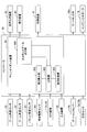
- FIG. 3 is a diagram illustrating the configuration of the controller 30 and the machine guidance device 50 in the embodiment.
- the controller 30 controls the operation of the entire excavator including the engine controller 74.
- the controller 30 controls the gate lock valve 49a to be closed when the gate lock lever 49 is depressed, and to open the gate lock valve 49a when the gate lock lever 49 is pulled up.
- the gate lock valve 49a is a switching valve provided in an oil passage between the control valve 17 and the operation levers 26A to 26C.
- the gate lock valve 49a is configured to open and close in response to a command from the controller 30, but is mechanically connected to the gate lock lever 49 and opens and closes according to the operation of the gate lock lever 49. Also good.
- the gate lock valve 49a blocks the flow of hydraulic oil between the control valve 17 and the operation levers 26A to 26C and invalidates the operation of the operation levers 26A to 26C. Further, in the open state, the gate lock valve 49a allows hydraulic oil to communicate between the control valve 17 and the operation lever to enable the operation of the operation levers 26A to 26C.
- the controller 30 detects the operation amount of each lever from the pilot pressure detected by the pressure sensors 15a and 15b in a state where the gate lock valve 49a is opened and the operation of the operation levers 26A to 26C is enabled.
- the controller 30 controls whether or not to perform guidance by the machine guidance device 50 in addition to controlling the operation of the entire shovel. Specifically, when it is determined that the excavator is at rest, the controller 30 sends a guidance stop command to the machine guidance device 50 so as to stop the guidance by the machine guidance device 50.
- controller 30 may output a guidance stop command to the machine guidance device 50 when outputting an auto idle stop command to the engine controller 74.
- controller 30 may output a guidance stop command to the machine guidance device 50 when it is determined that the gate lock lever 49 is in a depressed state.
- the machine guidance device 50 receives various signals and data supplied to the controller 30 from the boom angle sensor S1, the arm angle sensor S2, the bucket angle sensor S3, the vehicle body tilt sensor S4, the GPS device G1, the input device 45, and the like.
- the machine guidance device 50 receives information regarding the shape of the bucket 6 input by the input device 45.
- the information regarding the shape of the bucket 6 includes information such as the opening height and width of the bucket 6, the distance from the toe to the back, and the length of the nail.
- the machine guidance device 50 causes the storage device 47 to store target surface information including the depth of the target surface and the angle of the target surface input by the input device 45.
- the target surface information may be three-dimensional terrain data. In this case, it is desirable that the terrain data is associated with latitude, longitude, and altitude.
- the machine guidance device 50 calculates the actual operation position of the attachment such as the bucket 6 based on the received signal and data. Then, the machine guidance device 50 compares the actual operation position of the attachment with the target surface, and calculates, for example, a distance between the bucket 6 and the target surface. The machine guidance device 50 also calculates the distance from the pivot center axis of the shovel to the tip of the bucket 6, the inclination angle of the target surface, and the like, and transmits these to the display device 40 as work information.
- the machine guidance device 50 and the controller 30 are provided separately, the machine guidance device 50 and the controller 30 are connected to each other through a CAN (Controller Area Network).
- CAN Controller Area Network
- the machine guidance device 50 includes a height calculation unit 503, a comparison unit 504, a display control unit 505, and a guidance data output unit 506.
- the height calculation unit 503 calculates the height of the tip (toe) of the bucket 6 from the angles of the boom 4, the arm 5, and the bucket 6 obtained from the detection signals of the boom angle sensor S 1, the arm angle sensor S 2, and the bucket angle sensor S 3. calculate.
- the comparison unit 504 compares the height of the tip (toe) of the bucket 6 calculated by the height calculation unit 503 with the position of the target surface indicated in the guidance data output from the guidance data output unit 506.
- the comparison unit 504 of the present embodiment compares the height of the toe center position of the bucket 6 as the “representative position” with the position of the target surface. Further, the comparison unit 504 is configured so that the heights of the left and right positions of the toe of the bucket 6 as “positions other than the representative position” (specifically, the positions of the left end and the right end of the toe), The position of the target surface with respect to the left and right positions and the height of the back surface of the bucket 6 and the position of the target surface are compared.
- the comparison unit 504 calculates the relative distance between the representative position of the bucket 6 and the target surface at the “position other than the representative position” of the bucket 6. Various data obtained by the comparison unit 504 is stored in the storage device 47.
- the display control unit 505 transmits the height of the bucket 6 obtained by the comparison unit 504, the relative distance from the target surface, and the like to the display device 40 as work information.
- the display device 40 displays the work information sent from the display control unit 505 on the screen.
- the display screen configuration of the display device 40 will be described later.
- the display control unit 505 changes the notification content on the display screen of the display device 40 in accordance with the relative distance between an arbitrary position (the toe center position, the back position, etc.) of the bucket 6 and the target surface.
- the notification sound to the operator can be changed via the audio output device 43.
- the display control unit 505 displays an alarm on the display screen of the display device 40 or alerts the operator via the audio output device 43 when the bucket 6 is at a position lower than the target surface. Can be issued.
- FIG. 4 is a diagram illustrating a state in which the excavator in the embodiment is performing an operation of excavating a slope (inclined surface) with the bucket 6.
- FIG. 5 is a diagram illustrating a state of looking forward from the driver's seat in the excavator cabin 10 according to the embodiment.
- the bucket 6 can be seen from the front window of the cabin 10.
- the cabin 10 is provided with a driver's seat 10a in the center, and operation levers 26A and 26B are arranged on both sides thereof.
- the operator sits in the driver's seat 10a, operates the operation lever 26A with the left hand, and operates the operation lever 26B with the right hand, thereby moving the bucket 6 to a desired position and performing excavation work.
- the image display unit 41 and the switch panel 42 of the display device 40 are disposed in the front right of the driver's seat 10a (lower right of the front window).
- the operator of the shovel operates the operation levers 26A, 26B and the like with both hands while reading the work information from the image display unit 41 entering the field of view and looking at the bucket 6 outside the window.
- the image display unit 41 of the display device 40 displays a plurality of distance instruction units indicating relative distances from the target surface in correspondence with the width direction of the bucket 6. Such display control will be described below.
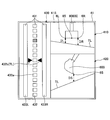
- FIG. 6 is a diagram showing a display example on the display screen 41S when the bucket 6 is located away from the target surface in the slope excavation work.
- FIG. 7 is a diagram illustrating a display example on the display screen 41 ⁇ / b> S when the bucket 6 approaches the target surface in the slope excavation work.
- FIG. 8 is a diagram illustrating a display example on the display screen 41 ⁇ / b> S when the bucket 6 is in a position that coincides with the target surface in the slope excavation work.
- FIG. 9 is a diagram showing a display example on the display screen 41S when the back surface of the bucket 6 is in a position in contact with the target surface in the slope excavation work.
- the display screen 41S includes a first target surface display image 410, a second target surface display image 420, and a distance display area 430, and displays various work information.
- the first target surface display image 410 schematically displays the relationship between the bucket 6 and the target surface.
- the bucket 6 and the target plane when the operator sits in the cabin 10 and looks at the front of the excavator are schematically displayed with the bucket icon 600 and the target plane TL.
- the bucket icon 600 is represented when the bucket 6 is viewed from the cabin 10.
- the target surface TL may be displayed together with the inclination angle of the bucket 6 with respect to the actual target surface.
- the distance DR and the distance DL between the bucket icon 600 and the target surface TL are displayed so as to change according to the actual distance from the tip of the bucket 6 to the target surface.
- the inclination angle of the bucket 6 is displayed so as to change according to the positional relationship between the actual bucket 6 and the target surface.
- the operator can grasp the positional relationship between the bucket 6 and the target surface and the inclination angle of the target surface by looking at the first target surface display image 410.
- the distance DR from the toe right side 6R position of the bucket icon 600 to the target surface TL, and the tip of the bucket icon 600 It can be visually recognized that the distance DL from the left 6L position to the target surface TL is different.
- the second target plane display image 420 schematically displays the relationship between the bucket 6 and the target plane when viewed from the side.
- a bucket icon 600 and a target plane TL are displayed.
- the bucket icon 600 is represented in a form in which the bucket 6 is viewed from the side.
- the target surface TL may be displayed together with an inclination angle with respect to the horizontal plane.
- a distance DS between the bucket icon 600 and the target surface TL is a distance from the position 6S of the tip of the toe center of the bucket icon 600 shown in the first target surface display image 410 to the target surface TL.
- the distance DS is displayed so as to change according to the distance from the actual toe center position of the bucket 6 to the target surface.
- the inclination angle is displayed so as to change according to the positional relationship between the actual bucket 6 and the target surface.
- the operator can grasp the positional relationship between the bucket 6 and the target surface and the inclination angle of the target surface by looking at the second target surface display image 420.
- the distance display area 430 includes a plurality of distance instruction units 431 that schematically indicate the distance from the target surface, corresponding to the width direction of the bucket 6.
- the distance instruction part 431 arranged at the center position is a graph display part 432 as a first distance display part.
- the distance instruction units 431 arranged on both sides of the graph display unit 432 are distance indicator display units 433 serving as second distance display units.
- the right side is a distance indicator display unit 433R, and the left side is a distance indicator display unit 433L.
- the graph display unit 432 displays the distance from the center position of the toe of the bucket 6 as the representative position to the target surface.
- the graph display unit 432 of the present embodiment displays the distance from the center 6S position of the toe center of the bucket icon 600 shown in the first target surface display image 410 to the target surface TL.
- the graph display unit 432 is a bar graph in which display segments 432a serving as a plurality of display units are arranged in parallel in the vertical direction at regular intervals.
- one of the 15 display segments 432a is displayed in a color (for example, black) different from that of the other bars according to the distance from the center position of the toe of the bucket 6 to the target surface.
- the segment 432a displayed in a different color is a bucket position display unit (the fourth display unit from the top in FIG. 10).
- the bucket position display unit is displayed so as to move up and down according to the distance from the center position of the toe of the bucket 6 to the target surface.
- the eighth display segment 432a from the top is the position of the target plane.
- a target instruction section 432b representing the position of the target plane is arranged.
- the bucket position display section becomes the eighth display segment 432a as shown in FIG. 8, and the display segment 432a may be displayed in green or the like.
- the bucket position display unit may be displayed in a color indicating a warning such as red.
- the bucket 6 has a distance DR from the toe right side 6R position of the bucket icon 600 to the target surface TL and a distance DL from the toe left side 6L position to the target surface TL as shown in the first target surface display image 410 of FIG. May be different.
- the distance indicator display unit 433R of the present embodiment displays the distance between the toe right side position of the bucket 6 and the target surface.
- the distance indicator display unit 433L displays the distance between the toe left side position of the bucket 6 and the target surface.
- the distance indicator display part 433R and the distance indicator display part 433L are one display bar extending in the vertical direction.
- the distance indicator display unit 433R and the distance indicator display unit 433L display different colors according to the distance from the left and right toe positions of the bucket 6 to the target surface.
- the distance indicator display unit 433R and the distance indicator display unit 433L are displayed in, for example, white when the bucket 6 is far from the target surface TL as shown in FIG. As shown in FIG. 7, when the position 6L on the left side of the toe of the bucket 6 coincides with the target surface TL, the distance indicator display portion 433L is displayed in green, for example. At this time, the distance indicator display unit 433R remains white. As shown in FIG. 8, when both the toe right side 6R position and the toe left side 6L position of the bucket 6 coincide with the target surface TL, the distance indicator display portions 433R and 433L are displayed in green.
- the distance indicator display unit 433R and the distance indicator display unit 433L of the present embodiment also display the distance between the back surface of the bucket 6 and the target surface.
- the bucket 6 during excavation work may have a back surface 6 b of the bucket 6 in contact with the target surface TL. At this time, the toe position of the bucket 6 is above the target surface TL.
- the distance indicator display unit 433R and the distance indicator display unit 433L are arranged so that the back surface 6b of the bucket 6 which is a position other than the representative position is in contact with the target surface TL and enters the lower side of the target surface TL.
- the insides of the indicator display portions 433L and 433R are made red, for example, to alert the operator.
- the controller 30 can issue an alarm to the operator via the audio output device 43.
- the display density can be changed periodically (blinking or blinking), or the shape of the bar can be changed (thickening or lengthening). Good. Visibility can be further improved by appropriately combining color change, blinking or blinking, and shape change.
- the range in which the color is changed may be not only the contact location but the entire bucket 6. In this way, by changing the schematic display form based on the position information other than the representative position, even if the portion of the bucket 6 other than the representative position has entered below the target surface TL, the operation is performed. The person can quickly stop the operation. Thereby, generation
- the operator intuitively determines the distance from the center position of the toe of the bucket 6 to the target surface, and the distance from the right position of the toe of the bucket 6 and the left position of the toe to the target surface. I can grasp. Further, the distance indicator display units 433R and 433L display that the back surface of the bucket 6 is in contact with the target surface by changing the display form (changing the color). Therefore, the operator can easily distinguish between FIG. 9 and FIG. 6 where the toe position of the bucket 6 is the same, and can perform highly accurate and efficient excavation work along the target surface.
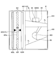
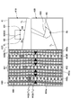
- FIG. 10 is a diagram showing another display example on the display screen 41S when the bucket 6 is located away from the target surface in the slope excavation work.
- FIG. 11 is a diagram showing another display example on the display screen 41S when the back surface of the bucket 6 is in a position in contact with the target surface in the slope excavation work.
- description of the display configuration common to FIGS. 6 to 9 will be omitted, and the description will focus on the differences.
- a distance display area 440 different from the above-described distance display area 430 is displayed in the left area of the display screen 41S shown in FIG.
- the distance display area 440 allows the distance between the toe center position, the toe right side position, and the toe left side position of the bucket 6 and the target surface to be separately viewed.
- the distance display area 440 includes a plurality of distance instruction sections 441 that schematically indicate the distance between each point of the bucket 6 and the target surface, corresponding to the width direction of the bucket 6.
- the distance instruction unit 441 arranged at the center position is a graph display unit 442 as a first distance display unit.
- the distance instruction units 441 arranged on both sides of the graph display unit 442 are graph display units 443 as a second distance display unit.
- the right side is a graph display unit 443R, and the left side is a graph display unit 443L.
- the first distance display unit and the second distance display unit have the same display form.
- the graph display unit 442 is a bar graph in which a plurality of display segments 442a are arranged in parallel at regular intervals in the vertical direction.
- the graph display unit 442 displays the distance from the center position of the toe of the bucket 6 to the target surface.
- one of the 15 display segments 442a is displayed in a color (for example, black) different from the other bars according to the distance from the center position of the toe of the bucket 6 to the target surface.
- the segment 442a displayed in a different color is a bucket position display unit (the fifth display unit from the top in FIG. 10).
- the bucket position display unit is displayed so as to move up and down according to the distance from the center position of the toe of the bucket 6 to the target surface.
- the graph display unit 443R and the graph display unit 443L have the same display configuration as the graph display unit 442 described above.
- the eighth display segments 442a and 443a from the top are the positions of the target planes.
- target instruction units 442b, 443b representing the position of the target surface are arranged.
- the graph display unit 442 may display the display segment 442a of the bucket position display unit in green or the like as shown in FIG.
- the bucket position display unit may be displayed in a color indicating a warning such as red.
- the same display form as that of the graph display unit 442 described above is implemented.
- the distance display area 440 includes a display area 444 provided separately from the distance instruction unit 441.
- the display area 444 is an area that becomes the background of the distance instruction unit 441.
- the display area 444 of the present embodiment displays the distance between the back surface of the bucket 6 and the target surface.
- the back surface 6b of the bucket 6 may come into contact with the target surface TL.
- the toe position of the bucket 6 is located above the target surface TL.
- the inside of the frame of the display area 444 is made red, for example, to alert the operator.
- the controller 30 can issue an alarm to the operator via the audio output device 43.
- the display density may be changed periodically (blinking or blinking), or the shape of the frame may be changed (thickened). Visibility can be further improved by appropriately combining color change, blinking or blinking, and shape change.
- you may change the color of the contact location of the back surface 6b of the bucket 6 into red, for example.
- the range in which the color is changed may be not only the contact location but the entire bucket 6.
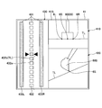
- FIG. 12 is a diagram showing still another display example on the display screen 41S when the bucket 6 is in a position away from the target surface in the slope excavation work.
- FIG. 13 is a diagram illustrating still another display example on the display screen 41S when the back surface of the bucket 6 is in a position in contact with the target surface in the slope excavation work.
- description of the display configuration common to FIGS. 6 to 11 will be omitted, and differences will be mainly described.
- a distance display area 450 different from the above-described distance display area 430 is displayed in the left area of the display screen 41S shown in FIG.
- the distance display area 450 is configured so that the distance between each of the toe right side position and the toe left side position of the bucket 6 and the target surface can be visually recognized separately.
- the distance display area 450 includes a plurality of distance instruction sections 451 that schematically indicate the distances between the points of the bucket 6 and the target surface, corresponding to the width direction of the bucket 6.
- the distance instruction unit 451 arranged on the right side is a graph display unit 452R as a first distance display unit.
- the distance instruction unit 451 arranged on the left side is a graph display unit 452L as a first distance display unit.
- the graph display unit 452R is a bar graph in which a plurality of display segments 452a are arranged in parallel at regular intervals in the vertical direction.
- the graph display unit 452R displays the distance from the right side of the toe of the bucket 6 to the target surface.
- one of the 15 display segments 452a is displayed in a color (for example, black) different from that of the other bars according to the distance from the right position on the toe of the bucket 6 to the target surface.
- the segment 452a displayed in a different color is a bucket position display section (the fourth display section from the top in FIG. 12).
- the bucket position display unit is displayed so as to move up and down according to the distance from the toe right side position of the bucket 6 to the target surface.
- the graph display unit 452L has the same display configuration as the graph display unit 452R described above.
- the eighth display segment 452a from the top is the position of the target plane.
- a target instruction section 452b representing the position of the target surface is arranged.
- the graph display unit 452R may display the display segment 452a of the bucket position display unit in green or the like as shown in FIG. 8 when the right side of the toe of the bucket 6 matches the target surface.
- the graph display portion 452L when the left side of the toe of the bucket 6 coincides with the target surface, the same display is performed.
- the bucket position display unit When the bucket 6 falls below the target plane, the bucket position display unit may be displayed in a color indicating a warning such as red.
- the distance display area 450 includes a display area 453 provided separately from the distance instruction unit 451.
- the display area 453 is an area that becomes the background of the distance instruction unit 451.
- the display area 453 of this embodiment displays the distance between the back surface of the bucket 6 and the target surface.
- the back surface 6b of the bucket 6 may come into contact with the target surface TL during the excavation work.
- the toe position of the bucket 6 is above the target surface TL.
- the controller 30 can issue an alarm to the operator via the audio output device 43.
- the display density may be changed periodically (blinking or blinking), or the shape of the frame may be changed (thickened). Visibility can be further improved by appropriately combining color change, blinking or blinking, and shape change.
- you may change the color of the contact location of the back surface 6b of the bucket 6 into red, for example.
- the range in which the color is changed may be not only the contact location but the entire bucket 6.
- the display screen 41S may include a fuel consumption display unit that displays fuel consumption, a hydraulic oil temperature display unit that displays the temperature state of the hydraulic oil in the hydraulic oil tank, and the like. Moreover, you may have a urea water residual amount display part, a fuel residual amount display part, a cooling water temperature display part, etc. Furthermore, the display method of each area is not limited to that exemplified in this embodiment. In addition, the arrangement of the regions is not limited to the configuration exemplified in the present embodiment. Further, in the case of an excavator equipped with an imaging device, the display screen 41S may display a camera image in addition to the above.
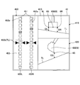
- FIG. 14 is a diagram illustrating another example of an image displayed on the image display unit 41.
- the display screen 41S shown in FIG. 14 includes a time display unit 411, a rotation speed mode display unit 412, a travel mode display unit 413, an attachment display unit 414, an engine control state display unit 415, a urea water remaining amount display unit 416, a fuel.
- a remaining amount display unit 417, a cooling water temperature display unit 418, an engine operating time display unit 419, a captured image display unit 460, and a work guidance display unit 470 are included.
- the time display unit 411 displays the current time. In the example shown in FIG. 14, the current time (10: 5) is shown.
- Rotation speed mode display unit 412 displays the rotation speed mode.
- the symbol “SP” representing the SP mode is displayed.
- Travel mode display unit 413 displays a travel mode.
- the traveling mode includes a low speed mode and a high speed mode, and a “turtle” mark is displayed in the low speed mode, and a “ ⁇ ” mark is displayed in the high speed mode.
- a “turtle” mark is displayed.
- the attachment display unit 414 displays an image representing the attached attachment, for example.
- the engine control state display unit 415 displays the control state of the engine 11.
- “automatic deceleration / automatic stop mode” is selected as the control state of the engine 11.
- the “automatic deceleration / automatic stop mode” automatically reduces the engine speed according to the duration of the low engine load, and automatically stops the engine 11 when the low engine load continues. This means the control state to be made.
- the control state of the engine 11 includes “automatic deceleration mode”, “automatic stop mode”, “manual deceleration mode”, and the like.
- the urea water remaining amount display section 416 displays a bar graph indicating the remaining amount of urea water stored in the urea water tank.
- the fuel remaining amount display portion 417 displays a bar graph indicating the remaining amount of fuel stored in the fuel tank.
- the cooling water temperature display unit 418 displays a bar graph indicating the temperature state of the engine cooling water.
- the engine operating time display unit 419 displays the accumulated operating time of the engine 11.
- the engine operation time display unit 419 displays the accumulated operation time since the excavator was manufactured or the accumulated operation time after the timer was restarted by the operator.
- the captured image display unit 460 displays an image captured by the imaging device, and displays an image captured by, for example, a rear monitoring camera, a left side monitoring camera, a right side monitoring camera, or the like.
- an imaging device icon 461 indicating the orientation of the imaging device that captured the image being displayed is displayed.
- the imaging device icon 461 includes a shovel icon 461a that represents the shape of the top view of the shovel and a band-shaped direction display icon 461b that represents the orientation of the imaging device that captured the image being displayed.
- a direction display icon 461 b is displayed below the excavator icon 461 a (opposite side of the attachment), and the captured image display unit 460 displays the rear image of the excavator captured by the rear monitoring camera. Is displayed.
- the operator can switch the image displayed on the captured image display unit 460 to an image captured by another camera, for example, by pressing an image switching button provided in the cabin 10.
- the rotation speed mode display unit 412, the traveling mode display unit 413, the attachment display unit 414, the engine control state display unit 415, and the imaging device icon 461 constitute a setting state display unit that indicates the setting state of the excavator.
- the urea water remaining amount display unit 416, the fuel remaining amount display unit 417, the cooling water temperature display unit 418, and the engine operating time display unit 419 constitute an operation state display unit that indicates the operation state of the excavator.
- an image including a plurality of distance instruction units 451 indicating the relative distance from the target surface corresponding to the width direction of the bucket 6 described above with reference to FIG. 12 is displayed. Is done.
- the numerical information image 471 the relative angle (30.0 °) of the orientation of the shovel with respect to the target surface is displayed together with an icon indicating the shovel.
- a preset relative distance (0.23 m) between the toe right position or the toe left position of the bucket 6 and the target surface is displayed together with a predetermined icon.
- the image shown in FIG. 12 is displayed on the image display unit 41.
- the image shown in FIG. 14 is displayed on the image display unit 41. You may be made to do. Whether or not the excavator is operated can be determined by the controller 30 based on the detection results of the pressure sensors 15a and 15b, for example.
Landscapes
- Engineering & Computer Science (AREA)
- Mining & Mineral Resources (AREA)
- Civil Engineering (AREA)
- General Engineering & Computer Science (AREA)
- Structural Engineering (AREA)
- Multimedia (AREA)
- Mechanical Engineering (AREA)
- Component Parts Of Construction Machinery (AREA)
Abstract
Description
走行動作を行う下部走行体と、
前記下部走行体に旋回自在に搭載される上部旋回体と、
前記上部旋回体に取り付けられたブーム、アーム、及びバケットを含むアタッチメントと、
該アタッチメントの操作をガイダンスするガイダンス装置と、
前記アタッチメントによる作業に関する情報が表示される表示装置と
を有するショベルであって、
前記ガイダンス装置は、前記バケットの幅方向に対応して、目標面との相対的な距離を模式的に示す複数の距離指示部を前記表示装置に表示することを特徴とするショベルが提供される。
3 上部旋回体
4 ブーム
5 アーム
6 バケット
10 キャビン(運転室)
40 表示装置
410 第1目標面表示画像
420 第2目標面表示画像
430、440、450 距離表示領域
Claims (10)
- 走行動作を行う下部走行体と、
前記下部走行体に旋回自在に搭載される上部旋回体と、
前記上部旋回体に取り付けられたブーム、アーム、及びバケットを含むアタッチメントと、
該アタッチメントの操作をガイダンスするガイダンス装置と、
前記アタッチメントによる作業に関する情報が表示される表示装置と
を有するショベルであって、
前記ガイダンス装置は、前記バケットの幅方向に対応して、目標面との相対的な距離を模式的に示す複数の距離指示部を前記表示装置に表示することを特徴とするショベル。 - 前記ガイダンス装置は、
前記バケットの爪先と背面までを含む前記目標面との相対距離を、前記表示装置に表示することを特徴とする請求項1に記載のショベル。 - 前記複数の距離指示部は、
前記バケットの代表位置と前記目標面との相対的な距離を示す第1距離表示部と、
前記バケットの前記代表位置以外の位置と前記目標面との相対的な距離を示す第2距離表示部とを含むことを特徴とする請求項1に記載のショベル。 - 前記第1距離表示部は、複数の表示部を上下方向に並列して形成されることを特徴とする請求項3に記載のショベル。
- 前記第2距離表示部は、前記バケットと前記目標面との相対的な距離を色又は濃度の変化で示すことを特徴とする請求項3に記載のショベル。
- 前記第2距離表示部は、前記第1距離表示部と同一の表示形態で表示されることを特徴とする請求項3に記載のショベル。
- 前記複数の距離指示部は、複数の表示部を上下方向に並列して形成されることを特徴とする請求項1に記載のショベル。
- 前記バケットの背面と前記目標面との相対的な距離は、前記第2距離表示部の表示形態の変化により表示することを特徴とする請求項3に記載のショベル。
- 前記バケットの背面と前記目標面との相対的な距離は、前記距離指示部とは別に設けられた表示領域の表示形態の変化により表示する請求項1に記載のショベル。
- 前記別に設けられた表示領域の変化とは、前記バケットの色の変化であることを特徴とする請求項9に記載のショベル。
Priority Applications (5)
| Application Number | Priority Date | Filing Date | Title |
|---|---|---|---|
| CN201780021498.1A CN108884668B (zh) | 2016-03-30 | 2017-03-27 | 挖土机 |
| JP2018507978A JP6862421B2 (ja) | 2016-03-30 | 2017-03-27 | ショベル及びショベルの表示装置 |
| KR1020187029080A KR102298318B1 (ko) | 2016-03-30 | 2017-03-27 | 쇼벨 및 쇼벨의 표시장치 |
| EP17774919.9A EP3438355A4 (en) | 2016-03-30 | 2017-03-27 | SHOVEL |
| US16/143,938 US10934689B2 (en) | 2016-03-30 | 2018-09-27 | Shovel |
Applications Claiming Priority (2)
| Application Number | Priority Date | Filing Date | Title |
|---|---|---|---|
| JP2016-068537 | 2016-03-30 | ||
| JP2016068537 | 2016-03-30 |
Related Child Applications (1)
| Application Number | Title | Priority Date | Filing Date |
|---|---|---|---|
| US16/143,938 Continuation US10934689B2 (en) | 2016-03-30 | 2018-09-27 | Shovel |
Publications (1)
| Publication Number | Publication Date |
|---|---|
| WO2017170382A1 true WO2017170382A1 (ja) | 2017-10-05 |
Family
ID=59965704
Family Applications (1)
| Application Number | Title | Priority Date | Filing Date |
|---|---|---|---|
| PCT/JP2017/012361 WO2017170382A1 (ja) | 2016-03-30 | 2017-03-27 | ショベル |
Country Status (6)
| Country | Link |
|---|---|
| US (1) | US10934689B2 (ja) |
| EP (1) | EP3438355A4 (ja) |
| JP (1) | JP6862421B2 (ja) |
| KR (1) | KR102298318B1 (ja) |
| CN (1) | CN108884668B (ja) |
| WO (1) | WO2017170382A1 (ja) |
Cited By (6)
| Publication number | Priority date | Publication date | Assignee | Title |
|---|---|---|---|---|
| JP2019116733A (ja) * | 2017-12-26 | 2019-07-18 | 日立建機株式会社 | 作業機械 |
| WO2019189430A1 (ja) * | 2018-03-28 | 2019-10-03 | コベルコ建機株式会社 | 建設機械 |
| KR20200033900A (ko) * | 2017-12-22 | 2020-03-30 | 히다찌 겐끼 가부시키가이샤 | 작업 기계 |
| EP4050166A1 (en) * | 2021-02-25 | 2022-08-31 | Hyundai Doosan Infracore Co., Ltd. | Machine guidance program and excavator using the same |
| JP2022180525A (ja) * | 2020-06-11 | 2022-12-06 | 日本精機株式会社 | 作業支援システム、作業支援方法 |
| JP7367001B2 (ja) | 2019-03-28 | 2023-10-23 | 住友建機株式会社 | ショベル及び施工システム |
Families Citing this family (1)
| Publication number | Priority date | Publication date | Assignee | Title |
|---|---|---|---|---|
| CN111622297B (zh) * | 2020-04-22 | 2021-04-23 | 浙江大学 | 一种挖掘机的在线作业纠偏系统和方法 |
Citations (7)
| Publication number | Priority date | Publication date | Assignee | Title |
|---|---|---|---|---|
| JP2001004376A (ja) * | 1999-06-25 | 2001-01-12 | Kumagai Gumi Co Ltd | 作業機械管理装置 |
| JP2004068433A (ja) * | 2002-08-07 | 2004-03-04 | Hitachi Constr Mach Co Ltd | 掘削機械の表示システム及びそのプログラム |
| JP2013087577A (ja) * | 2011-10-21 | 2013-05-13 | Hitachi Constr Mach Co Ltd | 作業機の表示装置 |
| JP5476450B1 (ja) | 2012-11-19 | 2014-04-23 | 株式会社小松製作所 | 掘削機械の表示システム及び掘削機械 |
| JP2014205955A (ja) * | 2013-04-10 | 2014-10-30 | 株式会社小松製作所 | 掘削機械の施工管理装置、油圧ショベルの施工管理装置、掘削機械及び施工管理システム |
| JP2016068537A (ja) | 2014-10-02 | 2016-05-09 | キヤノン株式会社 | 液体吐出ヘッド |
| JP2016160741A (ja) * | 2015-03-05 | 2016-09-05 | 株式会社小松製作所 | 作業機械の画像表示システム、作業機械の遠隔操作システム及び作業機械 |
Family Cites Families (13)
| Publication number | Priority date | Publication date | Assignee | Title |
|---|---|---|---|---|
| JPS62169061U (ja) | 1986-04-11 | 1987-10-27 | ||
| ZA948824B (en) * | 1993-12-08 | 1995-07-11 | Caterpillar Inc | Method and apparatus for operating geography altering machinery relative to a work site |
| JP4144377B2 (ja) * | 2003-02-28 | 2008-09-03 | ソニー株式会社 | 画像処理装置および方法、記録媒体、並びにプログラム |
| GB0410415D0 (en) * | 2004-05-11 | 2004-06-16 | Bamford Excavators Ltd | Operator display system |
| JP5054832B2 (ja) * | 2011-02-22 | 2012-10-24 | 株式会社小松製作所 | 油圧ショベルの表示システム及びその制御方法 |
| CN104395536B (zh) * | 2012-07-19 | 2017-10-20 | 住友建机株式会社 | 挖土机 |
| US8965642B2 (en) * | 2012-10-05 | 2015-02-24 | Komatsu Ltd. | Display system of excavating machine and excavating machine |
| JP5465345B1 (ja) * | 2013-01-18 | 2014-04-09 | 株式会社小松製作所 | 油圧ショベル |
| JP6254429B2 (ja) * | 2013-11-29 | 2017-12-27 | 株式会社小松製作所 | トンネル掘削装置およびその制御方法 |
| JP5886962B1 (ja) * | 2014-05-15 | 2016-03-16 | 株式会社小松製作所 | 掘削機械の表示システム、掘削機械及び掘削機械の表示方法 |
| DE112014000106B4 (de) * | 2014-06-02 | 2017-04-06 | Komatsu Ltd. | Baumaschinen-Steuersystem, Baumaschine und Verfahren zum Steuern einer Baumaschine |
| US10161111B2 (en) * | 2014-09-09 | 2018-12-25 | Komatsu Ltd. | Display system of excavation machine, excavation machine, and image display method |
| KR101814589B1 (ko) * | 2015-10-23 | 2018-01-04 | 가부시키가이샤 고마쓰 세이사쿠쇼 | 작업 기계의 표시 시스템, 작업 기계 및 표시 방법 |
-
2017
- 2017-03-27 EP EP17774919.9A patent/EP3438355A4/en active Pending
- 2017-03-27 KR KR1020187029080A patent/KR102298318B1/ko active IP Right Grant
- 2017-03-27 WO PCT/JP2017/012361 patent/WO2017170382A1/ja active Application Filing
- 2017-03-27 JP JP2018507978A patent/JP6862421B2/ja active Active
- 2017-03-27 CN CN201780021498.1A patent/CN108884668B/zh active Active
-
2018
- 2018-09-27 US US16/143,938 patent/US10934689B2/en active Active
Patent Citations (8)
| Publication number | Priority date | Publication date | Assignee | Title |
|---|---|---|---|---|
| JP2001004376A (ja) * | 1999-06-25 | 2001-01-12 | Kumagai Gumi Co Ltd | 作業機械管理装置 |
| JP2004068433A (ja) * | 2002-08-07 | 2004-03-04 | Hitachi Constr Mach Co Ltd | 掘削機械の表示システム及びそのプログラム |
| JP2013087577A (ja) * | 2011-10-21 | 2013-05-13 | Hitachi Constr Mach Co Ltd | 作業機の表示装置 |
| JP5476450B1 (ja) | 2012-11-19 | 2014-04-23 | 株式会社小松製作所 | 掘削機械の表示システム及び掘削機械 |
| JP2014101664A (ja) * | 2012-11-19 | 2014-06-05 | Komatsu Ltd | 掘削機械の表示システム及び掘削機械 |
| JP2014205955A (ja) * | 2013-04-10 | 2014-10-30 | 株式会社小松製作所 | 掘削機械の施工管理装置、油圧ショベルの施工管理装置、掘削機械及び施工管理システム |
| JP2016068537A (ja) | 2014-10-02 | 2016-05-09 | キヤノン株式会社 | 液体吐出ヘッド |
| JP2016160741A (ja) * | 2015-03-05 | 2016-09-05 | 株式会社小松製作所 | 作業機械の画像表示システム、作業機械の遠隔操作システム及び作業機械 |
Non-Patent Citations (1)
| Title |
|---|
| See also references of EP3438355A4 |
Cited By (10)
| Publication number | Priority date | Publication date | Assignee | Title |
|---|---|---|---|---|
| KR20200033900A (ko) * | 2017-12-22 | 2020-03-30 | 히다찌 겐끼 가부시키가이샤 | 작업 기계 |
| KR102314498B1 (ko) | 2017-12-22 | 2021-10-19 | 히다찌 겐끼 가부시키가이샤 | 작업 기계 |
| JP2019116733A (ja) * | 2017-12-26 | 2019-07-18 | 日立建機株式会社 | 作業機械 |
| WO2019189430A1 (ja) * | 2018-03-28 | 2019-10-03 | コベルコ建機株式会社 | 建設機械 |
| JP2019173352A (ja) * | 2018-03-28 | 2019-10-10 | コベルコ建機株式会社 | 建設機械 |
| JP7087545B2 (ja) | 2018-03-28 | 2022-06-21 | コベルコ建機株式会社 | 建設機械 |
| US11421404B2 (en) | 2018-03-28 | 2022-08-23 | Kobelco Construction Machinery Co., Ltd. | Construction machine |
| JP7367001B2 (ja) | 2019-03-28 | 2023-10-23 | 住友建機株式会社 | ショベル及び施工システム |
| JP2022180525A (ja) * | 2020-06-11 | 2022-12-06 | 日本精機株式会社 | 作業支援システム、作業支援方法 |
| EP4050166A1 (en) * | 2021-02-25 | 2022-08-31 | Hyundai Doosan Infracore Co., Ltd. | Machine guidance program and excavator using the same |
Also Published As
| Publication number | Publication date |
|---|---|
| EP3438355A4 (en) | 2019-03-20 |
| KR20180129815A (ko) | 2018-12-05 |
| US10934689B2 (en) | 2021-03-02 |
| CN108884668B (zh) | 2022-06-07 |
| US20190024347A1 (en) | 2019-01-24 |
| EP3438355A1 (en) | 2019-02-06 |
| KR102298318B1 (ko) | 2021-09-03 |
| CN108884668A (zh) | 2018-11-23 |
| JP6862421B2 (ja) | 2021-04-21 |
| JPWO2017170382A1 (ja) | 2019-02-07 |
Similar Documents
| Publication | Publication Date | Title |
|---|---|---|
| WO2017170382A1 (ja) | ショベル | |
| JP6965160B2 (ja) | ショベル | |
| JP7216549B2 (ja) | ショベル | |
| JP6644871B2 (ja) | ショベル及びショベルの表示装置 | |
| US20180016771A1 (en) | Shovel | |
| KR20190055098A (ko) | 쇼벨 | |
| US20200165798A1 (en) | Shovel, display device for shovel, and display method for shovel | |
| JP2017110472A (ja) | ショベル | |
| JP7003107B2 (ja) | ショベル | |
| JP2017210729A (ja) | ショベル | |
| JP2024031019A (ja) | ショベルの表示装置 |
Legal Events
| Date | Code | Title | Description |
|---|---|---|---|
| WWE | Wipo information: entry into national phase |
Ref document number: 2018507978 Country of ref document: JP |
|
| NENP | Non-entry into the national phase |
Ref country code: DE |
|
| ENP | Entry into the national phase |
Ref document number: 20187029080 Country of ref document: KR Kind code of ref document: A |
|
| WWE | Wipo information: entry into national phase |
Ref document number: 2017774919 Country of ref document: EP |
|
| ENP | Entry into the national phase |
Ref document number: 2017774919 Country of ref document: EP Effective date: 20181030 |
|
| 121 | Ep: the epo has been informed by wipo that ep was designated in this application |
Ref document number: 17774919 Country of ref document: EP Kind code of ref document: A1 |