EP3438355A1 - Shovel - Google Patents
Shovel Download PDFInfo
- Publication number
- EP3438355A1 EP3438355A1 EP17774919.9A EP17774919A EP3438355A1 EP 3438355 A1 EP3438355 A1 EP 3438355A1 EP 17774919 A EP17774919 A EP 17774919A EP 3438355 A1 EP3438355 A1 EP 3438355A1
- Authority
- EP
- European Patent Office
- Prior art keywords
- display
- bucket
- distance
- target surface
- display part
- Prior art date
- Legal status (The legal status is an assumption and is not a legal conclusion. Google has not performed a legal analysis and makes no representation as to the accuracy of the status listed.)
- Pending
Links
- 230000008859 change Effects 0.000 claims description 17
- 238000010586 diagram Methods 0.000 description 26
- 239000010720 hydraulic oil Substances 0.000 description 13
- 238000009412 basement excavation Methods 0.000 description 10
- 239000000446 fuel Substances 0.000 description 10
- XLYOFNOQVPJJNP-UHFFFAOYSA-N water Substances O XLYOFNOQVPJJNP-UHFFFAOYSA-N 0.000 description 8
- XSQUKJJJFZCRTK-UHFFFAOYSA-N Urea Chemical compound NC(N)=O XSQUKJJJFZCRTK-UHFFFAOYSA-N 0.000 description 7
- 239000004202 carbamide Substances 0.000 description 7
- 239000003086 colorant Substances 0.000 description 7
- 239000002826 coolant Substances 0.000 description 7
- 238000006243 chemical reaction Methods 0.000 description 5
- 230000004044 response Effects 0.000 description 5
- 230000001133 acceleration Effects 0.000 description 4
- 230000006870 function Effects 0.000 description 4
- 230000007246 mechanism Effects 0.000 description 4
- 238000012544 monitoring process Methods 0.000 description 4
- 230000001186 cumulative effect Effects 0.000 description 3
- 238000006073 displacement reaction Methods 0.000 description 3
- 241000270666 Testudines Species 0.000 description 2
- 238000001514 detection method Methods 0.000 description 2
- 238000005259 measurement Methods 0.000 description 2
- 239000003921 oil Substances 0.000 description 2
- 238000012545 processing Methods 0.000 description 2
- 241000283973 Oryctolagus cuniculus Species 0.000 description 1
- 239000008186 active pharmaceutical agent Substances 0.000 description 1
- 230000000881 depressing effect Effects 0.000 description 1
- 230000000694 effects Effects 0.000 description 1
- 239000012530 fluid Substances 0.000 description 1
- 239000002828 fuel tank Substances 0.000 description 1
- 239000004973 liquid crystal related substance Substances 0.000 description 1
- 238000004519 manufacturing process Methods 0.000 description 1
- 239000012528 membrane Substances 0.000 description 1
- 238000012986 modification Methods 0.000 description 1
- 230000004048 modification Effects 0.000 description 1
- 239000004065 semiconductor Substances 0.000 description 1
- 238000005507 spraying Methods 0.000 description 1
- 239000007858 starting material Substances 0.000 description 1
Images


Classifications
-
- E—FIXED CONSTRUCTIONS
- E02—HYDRAULIC ENGINEERING; FOUNDATIONS; SOIL SHIFTING
- E02F—DREDGING; SOIL-SHIFTING
- E02F9/00—Component parts of dredgers or soil-shifting machines, not restricted to one of the kinds covered by groups E02F3/00 - E02F7/00
- E02F9/26—Indicating devices
- E02F9/264—Sensors and their calibration for indicating the position of the work tool
-
- B—PERFORMING OPERATIONS; TRANSPORTING
- B60—VEHICLES IN GENERAL
- B60R—VEHICLES, VEHICLE FITTINGS, OR VEHICLE PARTS, NOT OTHERWISE PROVIDED FOR
- B60R1/00—Optical viewing arrangements; Real-time viewing arrangements for drivers or passengers using optical image capturing systems, e.g. cameras or video systems specially adapted for use in or on vehicles
- B60R1/20—Real-time viewing arrangements for drivers or passengers using optical image capturing systems, e.g. cameras or video systems specially adapted for use in or on vehicles
- B60R1/22—Real-time viewing arrangements for drivers or passengers using optical image capturing systems, e.g. cameras or video systems specially adapted for use in or on vehicles for viewing an area outside the vehicle, e.g. the exterior of the vehicle
- B60R1/28—Real-time viewing arrangements for drivers or passengers using optical image capturing systems, e.g. cameras or video systems specially adapted for use in or on vehicles for viewing an area outside the vehicle, e.g. the exterior of the vehicle with an adjustable field of view
-
- E—FIXED CONSTRUCTIONS
- E02—HYDRAULIC ENGINEERING; FOUNDATIONS; SOIL SHIFTING
- E02F—DREDGING; SOIL-SHIFTING
- E02F3/00—Dredgers; Soil-shifting machines
- E02F3/04—Dredgers; Soil-shifting machines mechanically-driven
- E02F3/28—Dredgers; Soil-shifting machines mechanically-driven with digging tools mounted on a dipper- or bucket-arm, i.e. there is either one arm or a pair of arms, e.g. dippers, buckets
- E02F3/30—Dredgers; Soil-shifting machines mechanically-driven with digging tools mounted on a dipper- or bucket-arm, i.e. there is either one arm or a pair of arms, e.g. dippers, buckets with a dipper-arm pivoted on a cantilever beam, i.e. boom
- E02F3/32—Dredgers; Soil-shifting machines mechanically-driven with digging tools mounted on a dipper- or bucket-arm, i.e. there is either one arm or a pair of arms, e.g. dippers, buckets with a dipper-arm pivoted on a cantilever beam, i.e. boom working downwardly and towards the machine, e.g. with backhoes
-
- B—PERFORMING OPERATIONS; TRANSPORTING
- B60—VEHICLES IN GENERAL
- B60R—VEHICLES, VEHICLE FITTINGS, OR VEHICLE PARTS, NOT OTHERWISE PROVIDED FOR
- B60R2300/00—Details of viewing arrangements using cameras and displays, specially adapted for use in a vehicle
- B60R2300/10—Details of viewing arrangements using cameras and displays, specially adapted for use in a vehicle characterised by the type of camera system used
- B60R2300/105—Details of viewing arrangements using cameras and displays, specially adapted for use in a vehicle characterised by the type of camera system used using multiple cameras
-
- E—FIXED CONSTRUCTIONS
- E02—HYDRAULIC ENGINEERING; FOUNDATIONS; SOIL SHIFTING
- E02F—DREDGING; SOIL-SHIFTING
- E02F9/00—Component parts of dredgers or soil-shifting machines, not restricted to one of the kinds covered by groups E02F3/00 - E02F7/00
- E02F9/20—Drives; Control devices
Definitions
- the present invention relates to shovels.
- the relative distance of a bucket to a target surface is displayed on the screen of a display device installed diagonally in front of an operator seat.
- a shovel that sets measurement reference points for measuring a bucket position at multiple points on a bucket, calculates the measurement reference point closest to a target surface, and displays the relative distance of the bucket position closest to the target surface to the target surface.
- the relative distance is displayed in a single (one-piece) distance display part.
- Patent Document 1 Japanese Patent No. 5476450
- the relative distance of the bucket position closest to the target surface to the target surface is displayed in a single distance information part. Therefore, when the bucket position closest to the target surface automatically changes because of a change in the bucket position and a change in the target surface caused by excavation, an operator cannot intuitively determine of which position on the bucket the relative distance to the target surface displayed in the distance display part is.
- a shovel operator normally performs work while looking at the tips of teeth of a bucket or an excavation site positioned in front of an operator seat, and therefore, cannot look at a display device for a long time during work. Accordingly, the shovel operator can look at the display device for an extremely short time during work, and may have difficulty in checking desired information from an image displayed on the display device within the time.
- an object is to provide a shovel including a display device that allows an operator to accurately and intuitively understand the relative distance of a bucket to a target surface without concentrating on a display screen.
- a shovel includes a traveling undercarriage configured to travel, an upper rotating structure swingably mounted on the traveling undercarriage, an attachment attached to the upper rotating structure and including a boom, an arm, and a bucket, a guidance device configured to guide an operation of the attachment, and a display device configured to display information related to work by the attachment, where the guidance device is configured to display multiple distance indicating parts with respect to the width direction of the bucket on the display device, the distance indicating parts schematically indicating relative distances to a target surface.
- an operator can accurately and intuitively understand the relative distance of a bucket to a target surface without concentrating on a display screen.
- FIG. 1 is a side view illustrating a shovel according to an embodiment.
- An upper rotating structure 3 is mounted on a traveling undercarriage 1 of the shovel via a swing mechanism 2.
- a boom 4 is attached to the upper rotating structure 3.
- An arm 5 is attached to an end of the boom 4.
- a bucket 6 serving as an end attachment (a working part) is attached to an end of the arm 5.
- a slope bucket, a dredging bucket, a breaker or the like may alternatively be attached as an end attachment.
- the boom 4, the arm 5, and the bucket 6 form an excavation attachment as an example of an attachment, and are hydraulically driven by a boom cylinder 7, an arm cylinder 8, and a bucket cylinder 9, respectively.
- a boom angle sensor S1 is attached to the boom 4.
- An arm angle sensor S2 is attached to the arm 5.
- a bucket angle sensor S3 is attached to the bucket 6.
- a bucket tilt mechanism may be provided on the excavation attachment.
- the boom angle sensor S1, the arm angle sensor S2, and the bucket angle sensor S3 may be referred to as "posture sensors.”
- the boom angle sensor S1 detects the rotation angle of the boom 4.
- the boom angle sensor S1 is an acceleration sensor that detects the rotation angle of the boom 4 relative to the upper rotating structure 3 by detecting an inclination to a horizontal plane.
- the arm angle sensor S2 detects the rotation angle of the arm 5.
- the arm angle sensor S2 is an acceleration sensor that detects the rotation angle of the arm 5 relative to the boom 4 by detecting an inclination to a horizontal plane.
- the bucket angle sensor S3 detects the rotation angle of the bucket 6.
- the bucket angle sensor S3 is an acceleration sensor that detects the rotation angle of the bucket 6 relative to the arm 5 by detecting an inclination to a horizontal plane.
- the bucket angle sensor S3 When the excavation attachment is provided with a bucket tilt mechanism, the bucket angle sensor S3 additionally detects the rotation angle of the bucket 6 about a tilt axis.
- the boom angle sensor S1, the arm angle sensor S2, and the bucket angle sensor S3 may alternatively be potentiometers using a variable resistor, stroke sensors that detect the stroke amount of a corresponding hydraulic cylinder, or rotary encoders that detect a rotation angle about a connecting pin.
- Power sources such as an engine 11 and a body tilt sensor S4 are mounted on the upper rotating structure 3 and covered with a cover 3a.
- the body tilt sensor S4 detects the tilt angle of the upper rotating structure 3.
- the body tilt sensor S4 is an acceleration sensor that detects the tilt angle of the upper rotating structure 3 by detecting an inclination to a horizontal plane.
- a GPS device (a GNSS receiver) G1 is provided on top of the cover 3a of the upper rotating structure 3.
- the GPS devices G1 and G2 detect the position of the shovel using a GPS function, and feed position data to a machine guidance device 50 in a controller 30.
- the controller 30, a display device 40, an audio output device 43, an input device 45, and a storage device 47 are provided in a cabin 10.
- the controller 30 operates as a main control part to control the driving of the shovel.
- the controller 30 is composed of a processing unit including a CPU and an internal memory.
- the CPU executes a program stored in the internal memory to implement various functions of the controller 30.
- the controller 30 also operates as the machine guidance device 50 to guide shovel operations.
- the machine guidance device 50 notifies an operator of work information such as the distance between a target surface that is the surface of a target terrain set by the operator and the working part of the attachment.
- the distance between the target surface and the working part of the attachment is, for example, the distance between the target surface, and the end (teeth tips) of the bucket 6 as an end attachment and the back surface of the bucket 6.
- the machine guidance device 50 notifies the operator of work information through the display device 40, the audio output device 43, etc., to guide shovel operations.
- the machine guidance device 50 is incorporated into the controller 30 according to this embodiment, the machine guidance device 50 and the controller 30 may alternatively be provided separately.
- the machine guidance device 50 is composed of a processing unit including a CPU and an internal memory. The CPU executes a program stored in the internal memory to implement various functions of the machine guidance device 50.
- the display device 40 displays an image including various kinds of work information in response to a command from the machine guidance device 50 included in the controller 30.
- the display device 40 is, for example, an in-vehicle liquid crystal display connected to the machine guidance device 50.
- the audio output device 43 outputs various kinds of audio information in response to an audio output command from the machine guidance device 50 included in the controller 30.
- the audio output device 43 includes, for example, an in-vehicle speaker connected to the machine guidance device 50.
- the audio output device 43 may include an alarm such as a buzzer.
- the input device 45 is a device for inputting various kinds of information to the controller 30 including the machine guidance device 50 by the operator of the shovel.
- the input device 45 includes, for example, a membrane switch provided on the surface of the display device 40.
- the input device 45 may include a touchscreen or the like.
- the storage device 47 is a device for storing various kinds of information.
- the storage device 47 is, for example, a non-volatile storage medium such as a semiconductor memory.
- the storage device 47 stores various kinds of information output by the controller 30 including the machine guidance device 50, etc.
- a gate lock lever 49 is a mechanism provided between the door and the operator seat of the cabin 10 to prevent the shovel from being accidentally operated.
- the operator climbs onto the operator seat and pulls up the gate lock lever 49, the operator is prevented from getting out of the cabin 10 and various operating apparatuses become operable.
- the operator pushes down the gate lock lever 49, the operator can get out of the cabin 10 and various operating apparatuses become inoperable.
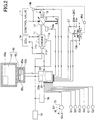
- FIG. 2 is a diagram illustrating a configuration of connections including the controller 30 of the shovel according to the embodiment.
- the display device 40 is provided in the cabin 10 to display an image including work information fed from the machine guidance device 50, etc.
- the display device 40 is connected to the controller 30 including the machine guidance device 50 via a communications network such as a Controller Area Network (CAN) or a Local Interconnect Network (LIN), a dedicated line, etc.
- a communications network such as a Controller Area Network (CAN) or a Local Interconnect Network (LIN), a dedicated line, etc.
- CAN Controller Area Network
- LIN Local Interconnect Network
- the display device 40 includes a conversion part 40a to generate an image to be displayed on an image display part 41.
- the conversion part 40a converts, into an image signal, data to be displayed on the image display part 41 among various kinds of data input to the display device 40 from the controller 30.
- the data input to the display device 40 from the controller 30 include, for example, data indicating the temperature of engine coolant water, data indicating the temperature of hydraulic oil, data indicating the remaining amount of an aqueous urea solution, data indicating the remaining amount of fuel, etc.
- the conversion part 40a outputs an image signal after conversion to the image display part 41 to display an image generated based on various kinds of data on the image display part 41.
- the conversion part 40a may be provided in not the display device 40 but, for example, the controller 30.
- the display device 40 includes a switch panel 42 serving as an input part.
- the switch panel 42 is a panel including various kinds of hardware switches.
- the switch panel 42 includes a light switch 42a, a windshield wiper switch 42b, and a window washer switch 42c.
- the light switch 42a is a switch for turning on and off lights attached to the exterior of the cabin 10.
- the windshield wiper switch 42b is a switch for moving and stopping a windshield wiper.
- the window washer switch 42c is a switch for spraying windshield washer fluid.
- the display device 40 is supplied with electric power from a rechargeable battery 70 to operate.
- the rechargeable battery 70 is charged with electric power generated in an alternator 11a (generator) of the engine 11.
- the electric power of the rechargeable battery 70 is also supplied to electrical equipment 72, etc., of the shovel besides the controller 30 and the display device 40.
- a starter 11b of the engine 11 is driven with electric power from the rechargeable battery 70 to start the engine 11.
- the engine 11 is connected to a main pump 14 and a pilot pump 15, and is controlled by an engine control unit (ECU) 74.
- ECU engine control unit
- Various data indicating the condition of the engine 11 for example, data indicating coolant water temperature (a physical quantity) detected with a water temperature sensor 11c, etc.
- the controller 30 can store these data in an internal temporary storage part (memory) 30a and suitably transmit the data to the display device 40.
- the main pump 14 is a hydraulic pump for supplying hydraulic oil to a control valve 17 via a highpressure hydraulic line.
- the main pump 14 is, for example, a swash-plate variable displacement hydraulic pump.
- the pilot pump 15 is a hydraulic pump for supplying hydraulic oil to various hydraulic control apparatuses via a pilot line.
- the pilot pump 15 is, for example, a fixed displacement hydraulic pump.
- the control valve 17 is a hydraulic controller to control the hydraulic system of the shovel.
- the control valve 17 selectively supplies hydraulic oil discharged by the main pump 14 to the boom cylinder 7, the arm cylinder 8, the bucket cylinder 9, traveling hydraulic motors, a swing hydraulic motor, etc.
- the boom cylinder 7, the arm cylinder 8, the bucket cylinder 9, the traveling hydraulic motors, and the swing hydraulic motor may be referred to as "hydraulic actuators.”
- Operating levers 26A through 26C are provided in the cabin 10 to be used by the operator to operate hydraulic actuators.
- hydraulic oil is supplied from the pilot pump to the pilot ports of flow control valves corresponding to hydraulic actuators.
- Each pilot port is supplied with hydraulic oil of a pressure commensurate with the direction of operation and the amount of operation of a corresponding one of the operating levers 26A through 26C.
- the operating lever 26A is a boom operating lever.
- the operator can hydraulically drive the boom cylinder 7 to operate the boom 4 when operating the operating lever 26A.
- the operating lever 26B is an arm operating lever.
- the operator can hydraulically drive the arm cylinder 8 to operate the arm 5 when operating the operating lever 26B.
- the operating lever 26C is a bucket operating lever.
- the operator can hydraulically drive the bucket cylinder 9 to operate the bucket 6 when operating the operating lever 26C.
- operating levers 26A through 26C operating levers, operating pedals, etc., for driving the traveling hydraulic motors, the swing hydraulic motor, etc., may be provided in the shovel.
- the controller 30 obtains, for example, various kinds of data described below.
- the data obtained by the controller 30 are stored in the temporary storage part 30a.
- Pressure sensors 15a and 15b detect a pilot pressure transmitted to the control valve 17 when the operating levers 26A through 26C are operated, and transmit data indicating the detected pilot pressure to the controller 30.
- the operating levers 26A through 26C are provided with a switch button 27. The operator can transmit a command signal to the controller 30 by operating the switch button 27 while operating the operating levers 26A through 26C.
- An engine rotational speed adjustment dial 75 is provided in the cabin 10 of the shovel.
- the engine rotational speed adjustment dial 75 is a dial for adjusting the rotational speed of the engine 11, and, for example, can switch the engine rotational speed in a stepwise manner.
- the engine rotational speed adjustment dial 75 is provided to make it possible to switch the engine rotational speed among the four levels of SP mode, H mode, A mode, and idling mode.
- the engine rotational speed adjustment dial 75 transmits data indicating the setting of the engine rotational speed to the controller 30.
- FIG. 2 illustrates a state where the H mode is selected by the engine rotational speed adjustment dial 75.
- the SP mode is a rotational speed mode selected when it is desired to prioritize workload, and uses the highest engine rotational speed.
- the H mode is a rotational speed mode selected when it is desired to satisfy both workload and fuel efficiency, and uses the second highest engine rotational speed.
- the A mode is a rotational speed mode selected when it is desired to operate the shovel with low noise while prioritizing fuel efficiency, and uses the third highest engine rotational speed.
- the idling mode is a rotational speed mode selected when it is desired to idle the engine, and uses the lowest engine rotational speed.
- the engine 11 is controlled to a constant rotational speed at the engine rotational speed of the rotational speed mode set by the engine rotational speed adjustment dial 75.
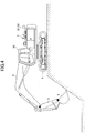
- FIG. 3 is a diagram illustrating a configuration of the controller 30 and the machine guidance device 50 according to the embodiment.
- the controller 30 controls the operation of the entire shovel including the engine controller 74.
- the controller 30 performs control to close a gate lock valve 49a when the gate lock lever 49 is pushed down and to open the gate lock valve 49a when the gate lock lever 49 is pulled up.
- the gate lock valve 49a is a selector valve provided in an oil passage between the control valve 17 and the operating levers 26A through 26C, etc.
- the gate lock valve 49a is configured to be opened or closed based on a command from the controller 30.
- the gate lock valve 49a may be mechanically connected to the gate lock lever 49 to be opened or closed in response to the operation of the gate lock lever 49.
- the gate lock valve 49a is closed to interrupt a flow of hydraulic oil between the control valve 17 and the operating levers 26A through 26C, etc., to disable the operating levers 26A through 26C, etc.
- the gate lock valve 49a is opened to allow passage of hydraulic oil between the control valve 17 and the operating levers, etc., to enable the operating levers 26A through 26C, etc.
- the controller 30 detects the amount of operation of each lever from a pilot pressure detected by the pressure sensor 15a or 15b with the gate lock valve 49a being opened to have the operating levers 26A through 26c enabled.
- the controller 30 controls whether to give guidance by the machine guidance device 50. Specifically, in response to determining that the shovel is not working, the controller 30 transmits a guidance stop command to the machine guidance device 50 to stop guidance by the machine guidance device 50.
- the controller 30 may output a guidance stop command to the machine guidance device 50 when outputting an automatic idling stop command to the engine controller 74.
- the controller 30 may output a guidance stop command to the machine guidance device 50 in response to determining that the gate lock lever 49 is pushed down.
- the machine guidance device 50 receives various signals and data supplied to the controller 30, from the boom angle sensor S1, the arm angle sensor S2, the bucket angle sensor S3, the body tilt sensor S4, the GPS device G1, the input device 45, etc.
- the machine guidance device 50 receives information pertaining to the shape of the bucket 6 input by the input device 45.
- the information pertaining to the shape of the bucket 6 includes information such as the opening height and the opening width, the distance from the teeth tips to the back surface, the teeth length, etc., of the bucket 6.
- the machine guidance device 50 stores target surface information input by the input device 45, including the depth of the target surface and the angle of the target surface, in the storage device 47.
- the target surface information may be three-dimensional terrain data. In this case, the terrain data are desirably associated with latitude, longitude, and altitude.
- the machine guidance device 50 calculates the actual operating position of the attachment such as the bucket 6 based on the received signals and data. Then, the machine guidance device 50 compares the actual operating position of the attachment and the target surface, and calculates, for example, the distance between the bucket 6 and the target surface. The machine guidance device 50 also calculates the distance from the swing central axis of the shovel to the teeth ends of the bucket 6, the inclination angle of the target surface, etc., and transmits these to the display device 40 as work information.
- the machine guidance device 50 and the controller 30 are provided separately, the machine guidance device 50 and the controller 30 are connected through CAN (Controller Area Network) to be able to communicate with each other.
- CAN Controller Area Network
- the machine guidance device 50 includes a height calculating part 503, a comparison part 504, a display control part 505, and a guidance data outputting part 506.
- the height calculating part 503 calculates the height of the end (teeth tips) of the bucket 6 from the angles of the boom 4, the arm 5, and the bucket 6 determined from the detection signals of the boom angle sensor S1, the arm angle sensor S2, and the bucket angle sensor S3.
- the comparison part 504 compares the height of the end (teeth tips) of the bucket 6 calculated by the height calculating part 503 and the position of the target surface shown in guidance data output by the guidance data outputting part 506.
- the comparison part 504 according to this embodiment compares the height of the position of the center of the teeth tips of the bucket 6 as a "representative position" and the position of the target surface.
- the comparison part 504 compares the respective heights of the left position and the right position of the teeth tips (specifically, the position of the left end and the position of the right end of the teeth tips) of the bucket 6 as "positions other than the representative position" and the positions of the target surface corresponding to the left position and the right position, and compares the height of the back surface of the bucket 6 and the position of the target surface.
- the comparison part 504 calculates a relative distance to the target surface at the representative position of the bucket 6 and a relative distance to the target surface at the "positions other than the representative position" of the bucket 6.
- Various data determined in the comparison part 504 are stored in the storage device 47.
- the display control part 505 transmits the height of the bucket 6 and the relative distances to the target surface as determined by the comparison part 504 to the display device 40 as work information.
- the display device 40 displays the work information transmitted from the display control part 505 on the screen.
- a display screen configuration of the display device 40 is described below.
- the display control part 505 can change the contents of a notification on the display screen of the display device 40 and change the sound of notification to the operator through the audio output device 43, in accordance with the relative distances between positions on the bucket 6 (the position of the center of the teeth tips, the position of the back surface, etc.) and the target surface. Furthermore, in such cases where the bucket 6 is positioned lower than the target surface, the display control part 505 can display a warning on the display screen of the display device 40 and issue an alarm to the operator through the audio output device 43.
- FIG. 4 is a diagram illustrating the shovel performing the work of excavating a slope (an inclined surface) with the bucket 6 according to the embodiment.
- FIG. 5 is a diagram illustrating a forward looking view from an operator seat in the cabin 10 of the shovel according to the embodiment.
- the bucket 6 can be seen from the front window of the cabin 10.
- an operator seat 10a is provided in the center, and the operating levers 26A and 26B are placed one on each side of the operator seat 10a.
- the operator is seated on the operator seat 10a and performs excavation work by moving the bucket 6 to a desired position by operating the operating lever 26A with the left hand and operating the operating lever 26B with the right hand.
- the image display part 41 and the switch panel 42 of the display device 40 are placed on the front right of the operator seat 10a (on the lower right of the front window).
- the operator of the shovel operates the operating levers 26A and 26B, etc., with both hands while looking at the bucket 6 outside the window, reading work information from the image display part 41 that comes into sight.
- the operator gazes at the bucket 6 outside the window during operations. Therefore, it is difficult for the operator to read the details of the information displayed on the image display part 41 that is in sight.
- the image display part 41 of the display device 40 displays multiple distance indicating parts indicating relative distances to the target surface, with respect to the width direction of the bucket 6. Such display control is described below.
- FIG. 6 is a diagram illustrating an example display on the display screen 41S in the case where the bucket 6 is at a position distant from a target surface in slope excavating work.
- FIG. 7 is a diagram illustrating an example display on the display screen 41S in the case where the bucket 6 has approached the target surface in slope excavating work.
- FIG. 8 is a diagram illustrating an example display on the display screen 41S in the case where the bucket 6 is at a position coinciding with the target surface in slope excavating work.
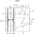
- FIG. 9 is a diagram illustrating an example display on the display screen 41S in the case where the back surface of the bucket 6 is at a position contacting the target surface in slope excavating work.
- the display screen 41S includes a first target surface display image 410, a second target surface display image 420, and a distance display region 430, and displays various kinds of work information.
- the first target surface display image 410 schematically displays the relationship between the bucket 6 and the target surface.
- the bucket 6 and the target surface in a forward looking view from the shovel that the operator has when seated in the cabin 10 are schematically displayed with a bucket icon 600 and a target surface TL.
- the bucket icon 600 is shown in the shape of the bucket 6 viewed from the cabin 10.
- the target surface TL may be displayed with the tilt angle of the bucket 6 relative to the actual target surface.
- a distance DR and a distance DL between the bucket icon 600 and the target surface TL are displayed in such a manner as to vary in accordance with the distance from the end of the actual bucket 6 to the target surface.
- the tilt angle of the bucket 6 is displayed in such a manner as to vary in accordance with the positional relationship between the actual bucket 6 and target surface.
- the operator can understand the positional relationship between the bucket 6 and the target surface and the inclination angle of the target surface by viewing the first target surface display image 410.
- the first target surface display image 410 illustrated in FIG. 6 it is possible to visually recognize with respect to the distance between the bucket icon 600 and the target surface TL that the distance DR from the position of a right side 6R of the teeth tips of the bucket icon 600 to the target surface TL is different from the distance DL from the position of a left side 6L of the teeth tips of the bucket icon 600 to the target surface TL.
- the second target surface display image 420 schematically displays the relationship between the bucket 6 and the target surface viewed from the side.
- the bucket icon 600 and the target surface TL are displayed.
- the bucket icon 600 is shown in the shape of the bucket 6 viewed from the side.
- the target surface TL may be displayed with an inclination angle relative to a horizontal plane.
- a distance DS between the bucket icon 600 and the target surface TL is the distance from the position of a center 6S of the teeth tips of the bucket icon 600 illustrated in the first target surface display image 410 to the target surface TL.
- the distance DL is displayed in such a manner as to vary in accordance with the distance from the position of the center of the teeth tips of the actual bucket 6 to the target surface.
- the inclination angle is displayed in such a manner as to vary in accordance with the positional relationship between the actual bucket 6 and target surface.
- the operator can understand the positional relationship between the bucket 6 and the target surface and the inclination angle of the target surface by viewing the second target surface display image 420.
- the distance display region 430 includes multiple distance indicating parts 431 that schematically indicate distances to the target surface, with respect to the width direction of the bucket 6.
- the distance indicating part 431 placed in the central position is a graph display part 432 serving as a first distance display part.
- the distance indicating parts 431 placed one on each side of the graph display part 432 are distance indicator display parts 433 serving as a second distance display part, of which one on the right side is a distance indicator display part 433R and of which one on the left side is a distance indicator display part 433L.
- the graph display part 432 displays the distance from the position of the center of the teeth tips of the bucket 6 as the representative position to the target surface.
- the graph display part 432 displays the distance from the position of the center 6S of the teeth tips of the bucket icon 600 shown in the first target surface display image 410 to the target surface TL.
- the graph display part 432 is a bar graph in which display segments 432a serving as multiple display parts are vertically arranged at regular intervals.
- one of the fifteen display segments 432a is displayed in a color (for example, black) different from that of other bars in accordance with the distance from the position of the center of the teeth tips of the bucket 6 to the target surface.
- the segment 432a displayed in the different color serves as a bucket position display part (the fourth display part from the top in FIG. 10 ).
- the bucket position display part is displayed in such a manner as to vertically move in accordance with the distance from the position of the center of the teeth tips of the bucket 6 to the target surface.
- the eighth display segment 432a from the top is the position of the target surface.
- Target indicating parts 432b indicating the position of the target surface are placed one on each lateral side of the eighth display segment 432a from the top.
- the bucket position display part is the eighth display segment 432a as illustrated in FIG. 8 , and the display segment 432a may be displayed in green.
- the bucket position display part may be displayed in a color indicating a warning, such as red.
- the distance DR from the position of the right side 6R of the teeth tips of the bucket icon 600 to the target surface TL may be different from the distance DL from the position of the left side 6L of the teeth tips of the bucket icon 600 to the target surface TL.
- the distance indicator display part 433R displays the distance between the position of the right side of the teeth tips of the bucket 6 and the target surface
- the distance indicator display part 433L displays the distance between the position of the left side of the teeth tips of the bucket 6 and the target surface.
- the distance indicator display part 433R and the distance indicator display part 433L are vertically elongated one-piece bars. According to this embodiment, the distance indicator display part 433R and the distance indicator display part 433L are displayed in different colors in accordance with the distance from the left or right position of the teeth tips of the bucket 6 to the target surface.
- the distance indicator display part 433R and the distance indicator display part 433L are displayed in, for example, white.
- the distance indicator display part 433L is displayed in, for example, green.
- the distance indicator display part 433R remains displayed in white.
- the distance indicator display parts 433R and 433L are displayed in green.
- the distance indicator display part 433R and the distance indicator display part 433L of this embodiment also display the distance between the back surface of the bucket 6 and the target surface.
- a back surface 6b of the bucket 6 may contact the target surface TL as illustrated in FIG. 9 .
- the position of the teeth tips of the bucket 6 at this point is above the target surface TL.
- the controller 30 may issue an alarm to the operator through the audio output device 43.
- the display configuration illustrated in FIG. 9 in addition to changing display colors, it is also possible to periodically change display density (to light off intermittently or light up intermittently) or change the shape of (widen or elongate) a bar.
- a suitable combination of changing colors, lighting off intermittently or lighting up intermittently, and changing a shape makes it possible to further improve the visibility.
- the color of the contacting area of the back surface 6b of the bucket 6 may be changed to, for example, red.
- the area of a color change is not limited to the contact area, and may be the entire bucket 6.
- the operator can immediately stop operations particularly when a part of the bucket 6 other than the representative position goes beneath the target surface TL. This makes it possible to reduce the occurrence of additional work such as backfilling.
- the distance indicator display parts 433R and 433L display the contact of the back surface of the bucket 6 with the target surface by changing a form of display (changing a color). Accordingly, the operator can easily distinguish FIGS. 6 and 9 in which the position of the teeth tips of the bucket 6 is the same, and can efficiently perform excavation work along the target surface with high accuracy.
- FIG. 10 is a diagram illustrating another example display on the display screen 41S in the case where the bucket 6 is at a position distant from a target surface in slope excavating work.
- FIG. 11 is a diagram illustrating another example display on the display screen 41S in the case where the back surface of the bucket 6 is at a position contacting the target surface in slope excavating work.
- a description of the same display configuration as in FIGS. 6 through 9 is omitted, and a description is given mainly of differences.
- a distance display region 440 different from the above-described distance display region 430 is displayed in the left-side region of the display screen 41S illustrated in FIG. 10 .
- the distance display region 440 makes it possible to visually recognize the respective distances of the position of the center, the position of the right side, and the position of the left side of the bucket 6 to the target surface separately.
- the distance display region 440 includes multiple distance indicating parts 441 that schematically indicate the distance between each point on the bucket 6 and the target surface, with respect to the width direction of the bucket 6.
- the distance indicating part 441 placed in the central position is a graph display part 442 serving as a first distance display part.
- the distance indicating parts 441 placed one on each side of the graph display part 442 are graph display parts 443 serving as a second distance display part, of which one on the right side is a graph display part 443R and of which one on the left side is a graph display part 443L.
- the first distance display part and the second distance display part are of the same form of display.
- the graph display part 442 is a bar graph in which display segments 442a are vertically arranged at regular intervals.
- the graph display part 442 displays the distance from the position of the center of the teeth tips of the bucket 6 to the target surface.
- one of the fifteen display segments 442a is displayed in a color (for example, black) different from that of other bars in accordance with the distance from the position of the center of the teeth tips of the bucket 6 to the target surface.
- the segment 442a displayed in the different color serves as a bucket position display part (the fifth display part from the top in FIG. 10 ).
- the bucket position display part is displayed in such a manner as to vertically move in accordance with the distance from the position of the center of the teeth tips of the bucket 6 to the target surface.
- the graph display part 443R and the graph display part 443L have the same display configuration as the above-described graph display part 442.
- the eighth display segment 442a or 443a from the top is the position of the target surface.
- Target indicating parts 442b and 443b indicating the position of the target surface are placed one on each lateral side of the eighth display segments 442a and 443a from the top, respectively.
- the graph display part 442 may display the display segment 442a of the bucket position display part in green as illustrated in FIG. 8 .
- the bucket position display part may be displayed in a color indicating a warning, such as red.
- the same form of display as in the above-described graph display part 442 is implemented.
- the distance display region 440 includes a display region 444 provided separately from the distance indicating parts 441.
- the display region 444 is a region that serves as the background of the distance indicating parts 441.
- the display region 444 displays the distance between the back surface of the bucket 6 and the target surface.
- the back surface 6b of the bucket 6 may contact the target surface TL as illustrated in FIG. 11 .
- the position of the teeth tips of the bucket 6 at this point is above the target surface TL.
- the controller 30 may issue an alarm to the operator through the audio output device 43.
- the display configuration illustrated in FIG. 11 in addition to changing display colors, it is also possible to periodically change display density (to light off intermittently or light up intermittently) or change the shape of (widen or elongate) the frame.
- a suitable combination of changing colors, lighting off intermittently or lighting up intermittently, and changing a shape makes it possible to further improve the visibility.
- the color of the contacting area of the back surface 6b of the bucket 6 may be changed to, for example, red.
- the area of a color change is not limited to the contact area, and may be the entire bucket 6.
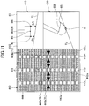
- FIG. 12 is a diagram illustrating yet another example display on the display screen 41S in the case where the bucket 6 is at a position distant from a target surface in slope excavating work.
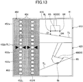
- FIG. 13 is a diagram illustrating yet another example display on the display screen 41S in the case where the back surface of the bucket 6 is at a position contacting the target surface in slope excavating work.
- a description of the same display configuration as in FIGS. 6 through 11 is omitted, and a description is given mainly of differences.
- a distance display region 450 different from the above-described distance display region 430 is displayed in the left-side region of the display screen 41S illustrated in FIG. 12 .
- the distance display region 450 makes it possible to visually recognize the respective distances of the position of the right side and the position of the left side of the bucket 6 to the target surface separately.
- the distance display region 450 includes multiple distance indicating parts 451 that schematically indicate the distance between each point on the bucket 6 and the target surface, with respect to the width direction of the bucket 6.
- the distance indicating part 451 placed on the right side is a graph display part 452R serving as a first distance display part.
- the distance indicating part 451 placed on the left side is a graph display part 452L serving as the first distance display part.
- the graph display part 452R is a bar graph in which display segments 452a are vertically arranged at regular intervals.
- the graph display part 452R displays the distance from the position of the right side of the teeth tips of the bucket 6 to the target surface.
- one of the fifteen display segments 452a is displayed in a color (for example, black) different from that of other bars in accordance with the distance from the position of the right side of the teeth tips of the bucket 6 to the target surface.
- the segment 452a displayed in the different color serves as a bucket position display part (the fourth display part from the top in FIG. 12 ).
- the bucket position display part is displayed in such a manner as to vertically move in accordance with the distance from the position of the right side of the teeth tips of the bucket 6 to the target surface.
- the graph display part 452L has the same display configuration as the above-described graph display part 452R.
- the eighth display segment 452a from the top is the position of the target surface.
- Target indicating parts 452b indicating the position of the target surface are placed one on each lateral side of the eighth display segments 452a from the top.
- the graph display part 452R may display the display segment 452a of the bucket position display part in green as illustrated in FIG. 8 .
- the same display is performed when the position of the left side of the teeth tips of the bucket 6 coincides with the target surface.
- the bucket position display part may be displayed in a color indicating a warning, such as red.
- the distance display region 450 includes a display region 453 provided separately from the distance indicating parts 451.
- the display region 453 is a region that serves as the background of the distance indicating parts 451.
- the display region 453 displays the distance between the back surface of the bucket 6 and the target surface.
- the back surface 6b of the bucket 6 may contact the target surface TL as illustrated in FIG. 13 .
- the position of the teeth tips of the bucket 6 at this point is above the target surface TL.
- the controller 30 may issue an alarm to the operator through the audio output device 43.
- the display configuration illustrated in FIG. 13 in addition to changing display colors, it is also possible to periodically change display density (to light off intermittently or light up intermittently) or change the shape of (widen or elongate) the frame.
- a suitable combination of changing colors, lighting off intermittently or lighting up intermittently, and changing a shape makes it possible to further improve the visibility.
- the color of the contacting area of the back surface 6b of the bucket 6 may be changed to, for example, red.
- the area of a color change is not limited to the contact area, and may be the entire bucket 6.
- the display screen 41S may include a fuel efficiency display part to display fuel efficiency and a hydraulic oil temperature display part to display the temperature condition of hydraulic oil in a hydraulic oil tank.
- the display screen 41S may further include a remaining aqueous urea solution amount display part, a remaining fuel amount display part, and a coolant water temperature display part.
- the form of display of the regions is not limited to the illustration of this embodiment.
- the arrangement of the regions is not limited to the configuration illustrated in this embodiment.
- the display screen 41S may display a camera image in addition to those described above.
- FIG. 14 is a diagram illustrating another example of the image displayed on the image display part 41.
- the display screen 41S illustrated in FIG. 14 includes a time display part 411, a rotational speed mode display part 412, a traveling mode display part 413, an attachment display part 414, an engine control status display part 415, a remaining aqueous urea solution amount display part 416, a remaining fuel amount display part 417, a coolant water temperature display part 418, an engine operating time display part 419, a captured image display part 460, and a work guidance display part 470.
- the time display part 411 displays a current time.
- a current time (10:05) is shown.
- the rotational speed mode display part 412 displays a rotational speed mode.
- a symbol "SP" representing SP mode is displayed.
- the traveling mode display part 413 displays a traveling mode.
- the traveling mode includes a low-speed mode and a high-speed mode.
- a "turtle"-shaped mark is displayed in the low-speed mode, and a "rabbit”-shaped mark is displayed in the high-speed mode.
- the "turtle"-shaped mark is displayed.
- the attachment display part 414 displays, for example, an image representing an attachment that is attached.
- the engine control status display part 415 displays the control status of the engine 11.
- "automatic deceleration and automatic stop mode” is selected as the control status of the engine 11.
- the “automatic deceleration and automatic stop mode” means a control status to automatically reduce the engine rotational speed in accordance with the duration of a condition in which the engine load is low and to automatically stop the engine 11 when the condition of the low engine load further continues.
- Other control statuses of the engine 11 include "automatic deceleration mode,” “automatic stop mode,” “manual deceleration mode,” etc.
- a bar graph representing the status of the remaining amount of an aqueous urea solution stored in an aqueous urea solution tank is displayed.
- a bar graph representing the status of the remaining amount of fuel stored in a fuel tank is displayed.
- coolant water temperature display part 418 a bar graph representing the temperature condition of engine coolant water is displayed.
- the engine operating time display part 419 displays the cumulative operating time of the engine 11. A cumulative operating time since the manufacture of the shovel or a cumulative operating time since the restart of a timer by the operator is displayed in the engine operating time display part 419.
- an image captured by an image capturing device is displayed, and for example, an image captured by a back-side monitoring camera, a left-side monitoring camera, or a right-side monitoring camera is displayed.
- an image capturing device icon 461 representing the orientation of an image capturing device that has captured an image that is being displayed is displayed.
- the image capturing device icon 461 is composed of a shovel icon 461a representing the shape of the shovel in a plan view and a strip-shaped orientation indicator icon 461b representing the orientation of the image capturing device that has captured the image that is being displayed.
- the orientation indicator icon 461b is displayed below the shovel icon 461a (on the opposite side from the attachment) to indicate that an image of an area behind the shovel captured with the back-side monitoring camera is displayed in the captured image display part 460.
- the operator can switch an image to display in the captured image display part 460 to an image captured by another camera by depressing an image switch button provided in the cabin 10.
- the above-described rotational speed mode display part 412, traveling mode display part 413, attachment display part 414, engine control status display part 415, and image capturing device icon 461 constitute a settings display part indicating the settings of the shovel. Furthermore, the remaining aqueous urea solution amount display part 416, the remaining fuel amount display part 417, the coolant water temperature display part 418, and the engine operating time display part 419 constitute an operating condition display part indicating the operating condition of the shovel.
- the work guidance display part 470 for example, an image including the distance indicating parts 451 indicating relative distances to the target surface with respect to the width direction of the bucket 6, as described above with reference to FIG. 12 , is displayed. Furthermore, here, the relative angle (30.0°) of the orientation of the shovel relative to the target surface is displayed as a numerical information image 471 along with an icon representing the shovel. In addition, as the numerical information image 471, the relative distance (0.23 m) between the position of the right side of the teeth tips or the position of the left side of the teeth tips of the bucket 6, which is preset, and the target surface is displayed along with a predetermined icon.
- the image illustrated in FIG. 12 may be displayed in the image display part 41
- the image illustrated in FIG. 14 may be displayed in the image display part 41.
- Whether the shovel is in operation or not may be determined by the controller 30 based on the detection results of the pressure sensors 15a and 15b, for example.
Abstract
Description
- The present invention relates to shovels.
- According to shovels with a machine guidance function, for example, the relative distance of a bucket to a target surface is displayed on the screen of a display device installed diagonally in front of an operator seat.
- For example, there is a shovel that sets measurement reference points for measuring a bucket position at multiple points on a bucket, calculates the measurement reference point closest to a target surface, and displays the relative distance of the bucket position closest to the target surface to the target surface. (See, for example,
Patent Document 1.) The relative distance is displayed in a single (one-piece) distance display part. - Patent Document 1: Japanese Patent No.
5476450 - According to the above-described shovel, the relative distance of the bucket position closest to the target surface to the target surface is displayed in a single distance information part. Therefore, when the bucket position closest to the target surface automatically changes because of a change in the bucket position and a change in the target surface caused by excavation, an operator cannot intuitively determine of which position on the bucket the relative distance to the target surface displayed in the distance display part is.
- A shovel operator normally performs work while looking at the tips of teeth of a bucket or an excavation site positioned in front of an operator seat, and therefore, cannot look at a display device for a long time during work. Accordingly, the shovel operator can look at the display device for an extremely short time during work, and may have difficulty in checking desired information from an image displayed on the display device within the time.
- Therefore, an object is to provide a shovel including a display device that allows an operator to accurately and intuitively understand the relative distance of a bucket to a target surface without concentrating on a display screen.
- To achieve the above-described object, according to an embodiment of the present invention, a shovel is provided that includes a traveling undercarriage configured to travel, an upper rotating structure swingably mounted on the traveling undercarriage, an attachment attached to the upper rotating structure and including a boom, an arm, and a bucket, a guidance device configured to guide an operation of the attachment, and a display device configured to display information related to work by the attachment, where the guidance device is configured to display multiple distance indicating parts with respect to the width direction of the bucket on the display device, the distance indicating parts schematically indicating relative distances to a target surface.
- According to the disclosed embodiment, an operator can accurately and intuitively understand the relative distance of a bucket to a target surface without concentrating on a display screen.
-
-
FIG. 1 is a side view illustrating a shovel according to an embodiment. -
FIG. 2 is a diagram illustrating a configuration of connections including a controller of the shovel. -
FIG. 3 is a diagram illustrating a configuration of the controller and a machine guidance device. -
FIG. 4 is a diagram illustrating slope excavating work by the shovel. -
FIG. 5 is a diagram illustrating a forward looking view from an operator seat in a cabin of the shovel. -
FIG. 6 is a diagram illustrating an example display on a display screen in the case where a bucket is at a position distant from a target surface. -
FIG. 7 is a diagram illustrating an example display on the display screen in the case where the bucket has approached the target surface. -
FIG. 8 is a diagram illustrating an example display on the display screen in the case where the bucket is at a position coinciding with the target surface. -
FIG. 9 is a diagram illustrating an example display on the display screen in the case where a back surface of the bucket is at a position contacting the target surface. -
FIG. 10 is a diagram illustrating another example display in the case where the bucket is at a position distant from the target surface. -
FIG. 11 is a diagram illustrating another example display in the case where the back surface of the bucket is at a position contacting the target surface. -
FIG. 12 is a diagram illustrating yet another example display in the case where the bucket is at a position distant from the target surface. -
FIG. 13 is a diagram illustrating yet another example display in the case where the back surface of the bucket is at a position contacting the target surface. -
FIG. 14 is a diagram illustrating another example of an image displayed on an image display part. -
FIG. 1 is a side view illustrating a shovel according to an embodiment. - An upper rotating
structure 3 is mounted on atraveling undercarriage 1 of the shovel via aswing mechanism 2. Aboom 4 is attached to the upper rotatingstructure 3. Anarm 5 is attached to an end of theboom 4. Abucket 6 serving as an end attachment (a working part) is attached to an end of thearm 5. A slope bucket, a dredging bucket, a breaker or the like may alternatively be attached as an end attachment. - The
boom 4, thearm 5, and thebucket 6 form an excavation attachment as an example of an attachment, and are hydraulically driven by a boom cylinder 7, anarm cylinder 8, and abucket cylinder 9, respectively. A boom angle sensor S1 is attached to theboom 4. An arm angle sensor S2 is attached to thearm 5. A bucket angle sensor S3 is attached to thebucket 6. A bucket tilt mechanism may be provided on the excavation attachment. The boom angle sensor S1, the arm angle sensor S2, and the bucket angle sensor S3 may be referred to as "posture sensors." - The boom angle sensor S1 detects the rotation angle of the
boom 4. For example, the boom angle sensor S1 is an acceleration sensor that detects the rotation angle of theboom 4 relative to the upper rotatingstructure 3 by detecting an inclination to a horizontal plane. - The arm angle sensor S2 detects the rotation angle of the
arm 5. For example, the arm angle sensor S2 is an acceleration sensor that detects the rotation angle of thearm 5 relative to theboom 4 by detecting an inclination to a horizontal plane. - The bucket angle sensor S3 detects the rotation angle of the
bucket 6. For example, the bucket angle sensor S3 is an acceleration sensor that detects the rotation angle of thebucket 6 relative to thearm 5 by detecting an inclination to a horizontal plane. - When the excavation attachment is provided with a bucket tilt mechanism, the bucket angle sensor S3 additionally detects the rotation angle of the
bucket 6 about a tilt axis. The boom angle sensor S1, the arm angle sensor S2, and the bucket angle sensor S3 may alternatively be potentiometers using a variable resistor, stroke sensors that detect the stroke amount of a corresponding hydraulic cylinder, or rotary encoders that detect a rotation angle about a connecting pin. - Power sources such as an
engine 11 and a body tilt sensor S4 are mounted on the upper rotatingstructure 3 and covered with acover 3a. The body tilt sensor S4 detects the tilt angle of the upperrotating structure 3. For example, the body tilt sensor S4 is an acceleration sensor that detects the tilt angle of the upper rotatingstructure 3 by detecting an inclination to a horizontal plane. - A GPS device (a GNSS receiver) G1 is provided on top of the
cover 3a of the upper rotatingstructure 3. The GPS devices G1 and G2 detect the position of the shovel using a GPS function, and feed position data to amachine guidance device 50 in acontroller 30. Thecontroller 30, adisplay device 40, anaudio output device 43, aninput device 45, and astorage device 47 are provided in acabin 10. - The
controller 30 operates as a main control part to control the driving of the shovel. Thecontroller 30 is composed of a processing unit including a CPU and an internal memory. The CPU executes a program stored in the internal memory to implement various functions of thecontroller 30. - The
controller 30 also operates as themachine guidance device 50 to guide shovel operations. For example, themachine guidance device 50 notifies an operator of work information such as the distance between a target surface that is the surface of a target terrain set by the operator and the working part of the attachment. The distance between the target surface and the working part of the attachment is, for example, the distance between the target surface, and the end (teeth tips) of thebucket 6 as an end attachment and the back surface of thebucket 6. Themachine guidance device 50 notifies the operator of work information through thedisplay device 40, theaudio output device 43, etc., to guide shovel operations. - While the
machine guidance device 50 is incorporated into thecontroller 30 according to this embodiment, themachine guidance device 50 and thecontroller 30 may alternatively be provided separately. In this case, like thecontroller 30, themachine guidance device 50 is composed of a processing unit including a CPU and an internal memory. The CPU executes a program stored in the internal memory to implement various functions of themachine guidance device 50. - The
display device 40 displays an image including various kinds of work information in response to a command from themachine guidance device 50 included in thecontroller 30. Thedisplay device 40 is, for example, an in-vehicle liquid crystal display connected to themachine guidance device 50. - The
audio output device 43 outputs various kinds of audio information in response to an audio output command from themachine guidance device 50 included in thecontroller 30. Theaudio output device 43 includes, for example, an in-vehicle speaker connected to themachine guidance device 50. Theaudio output device 43 may include an alarm such as a buzzer. - The
input device 45 is a device for inputting various kinds of information to thecontroller 30 including themachine guidance device 50 by the operator of the shovel. Theinput device 45 includes, for example, a membrane switch provided on the surface of thedisplay device 40. Theinput device 45 may include a touchscreen or the like. - The
storage device 47 is a device for storing various kinds of information. Thestorage device 47 is, for example, a non-volatile storage medium such as a semiconductor memory. Thestorage device 47 stores various kinds of information output by thecontroller 30 including themachine guidance device 50, etc. - A
gate lock lever 49 is a mechanism provided between the door and the operator seat of thecabin 10 to prevent the shovel from being accidentally operated. When the operator climbs onto the operator seat and pulls up thegate lock lever 49, the operator is prevented from getting out of thecabin 10 and various operating apparatuses become operable. When the operator pushes down thegate lock lever 49, the operator can get out of thecabin 10 and various operating apparatuses become inoperable. -
FIG. 2 is a diagram illustrating a configuration of connections including thecontroller 30 of the shovel according to the embodiment. - The
display device 40 is provided in thecabin 10 to display an image including work information fed from themachine guidance device 50, etc. Thedisplay device 40 is connected to thecontroller 30 including themachine guidance device 50 via a communications network such as a Controller Area Network (CAN) or a Local Interconnect Network (LIN), a dedicated line, etc. - The
display device 40 includes aconversion part 40a to generate an image to be displayed on animage display part 41. - The
conversion part 40a converts, into an image signal, data to be displayed on theimage display part 41 among various kinds of data input to thedisplay device 40 from thecontroller 30. The data input to thedisplay device 40 from thecontroller 30 include, for example, data indicating the temperature of engine coolant water, data indicating the temperature of hydraulic oil, data indicating the remaining amount of an aqueous urea solution, data indicating the remaining amount of fuel, etc. - The
conversion part 40a outputs an image signal after conversion to theimage display part 41 to display an image generated based on various kinds of data on theimage display part 41. - The
conversion part 40a may be provided in not thedisplay device 40 but, for example, thecontroller 30. Thedisplay device 40 includes aswitch panel 42 serving as an input part. Theswitch panel 42 is a panel including various kinds of hardware switches. Theswitch panel 42 includes alight switch 42a, awindshield wiper switch 42b, and awindow washer switch 42c. - The
light switch 42a is a switch for turning on and off lights attached to the exterior of thecabin 10. Thewindshield wiper switch 42b is a switch for moving and stopping a windshield wiper. Thewindow washer switch 42c is a switch for spraying windshield washer fluid. - The
display device 40 is supplied with electric power from arechargeable battery 70 to operate. Therechargeable battery 70 is charged with electric power generated in analternator 11a (generator) of theengine 11. The electric power of therechargeable battery 70 is also supplied toelectrical equipment 72, etc., of the shovel besides thecontroller 30 and thedisplay device 40. Furthermore, astarter 11b of theengine 11 is driven with electric power from therechargeable battery 70 to start theengine 11. - The
engine 11 is connected to amain pump 14 and apilot pump 15, and is controlled by an engine control unit (ECU) 74. Various data indicating the condition of the engine 11 (for example, data indicating coolant water temperature (a physical quantity) detected with awater temperature sensor 11c, etc.) are constantly transmitted from theECU 74 to thecontroller 30. Thecontroller 30 can store these data in an internal temporary storage part (memory) 30a and suitably transmit the data to thedisplay device 40. - The
main pump 14 is a hydraulic pump for supplying hydraulic oil to acontrol valve 17 via a highpressure hydraulic line. Themain pump 14 is, for example, a swash-plate variable displacement hydraulic pump. - The
pilot pump 15 is a hydraulic pump for supplying hydraulic oil to various hydraulic control apparatuses via a pilot line. Thepilot pump 15 is, for example, a fixed displacement hydraulic pump. - The
control valve 17 is a hydraulic controller to control the hydraulic system of the shovel. For example, thecontrol valve 17 selectively supplies hydraulic oil discharged by themain pump 14 to the boom cylinder 7, thearm cylinder 8, thebucket cylinder 9, traveling hydraulic motors, a swing hydraulic motor, etc. In the following, the boom cylinder 7, thearm cylinder 8, thebucket cylinder 9, the traveling hydraulic motors, and the swing hydraulic motor may be referred to as "hydraulic actuators." - Operating levers 26A through 26C are provided in the
cabin 10 to be used by the operator to operate hydraulic actuators. When the operating levers 26A through 26C are operated, hydraulic oil is supplied from the pilot pump to the pilot ports of flow control valves corresponding to hydraulic actuators. Each pilot port is supplied with hydraulic oil of a pressure commensurate with the direction of operation and the amount of operation of a corresponding one of the operating levers 26A through 26C. - According to this embodiment, the operating
lever 26A is a boom operating lever. The operator can hydraulically drive the boom cylinder 7 to operate theboom 4 when operating the operatinglever 26A. The operatinglever 26B is an arm operating lever. The operator can hydraulically drive thearm cylinder 8 to operate thearm 5 when operating the operatinglever 26B. The operatinglever 26C is a bucket operating lever. The operator can hydraulically drive thebucket cylinder 9 to operate thebucket 6 when operating the operatinglever 26C. Besides the operating levers 26A through 26C, operating levers, operating pedals, etc., for driving the traveling hydraulic motors, the swing hydraulic motor, etc., may be provided in the shovel. - The
controller 30 obtains, for example, various kinds of data described below. The data obtained by thecontroller 30 are stored in thetemporary storage part 30a. - A
regulator 14a of themain pump 14, which is a variable displacement hydraulic pump, transmits data indicating a swash plate angle to thecontroller 30. Furthermore, adischarge pressure sensor 14b transmits data indicating the discharge pressure of themain pump 14 to thecontroller 30. These data (data representing physical quantities) are stored in thetemporary storage part 30a. Furthermore, anoil temperature sensor 14c provided in a conduit between themain pump 14 and a tank storing hydraulic oil that themain pump 14 draws in transmits data representing the temperature of hydraulic oil flowing through the conduit to thecontroller 30. -
Pressure sensors control valve 17 when the operating levers 26A through 26C are operated, and transmit data indicating the detected pilot pressure to thecontroller 30. The operating levers 26A through 26C are provided with aswitch button 27. The operator can transmit a command signal to thecontroller 30 by operating theswitch button 27 while operating the operating levers 26A through 26C. - An engine rotational
speed adjustment dial 75 is provided in thecabin 10 of the shovel. The engine rotationalspeed adjustment dial 75 is a dial for adjusting the rotational speed of theengine 11, and, for example, can switch the engine rotational speed in a stepwise manner. According to this embodiment, the engine rotationalspeed adjustment dial 75 is provided to make it possible to switch the engine rotational speed among the four levels of SP mode, H mode, A mode, and idling mode. The engine rotationalspeed adjustment dial 75 transmits data indicating the setting of the engine rotational speed to thecontroller 30.FIG. 2 illustrates a state where the H mode is selected by the engine rotationalspeed adjustment dial 75. - The SP mode is a rotational speed mode selected when it is desired to prioritize workload, and uses the highest engine rotational speed. The H mode is a rotational speed mode selected when it is desired to satisfy both workload and fuel efficiency, and uses the second highest engine rotational speed. The A mode is a rotational speed mode selected when it is desired to operate the shovel with low noise while prioritizing fuel efficiency, and uses the third highest engine rotational speed. The idling mode is a rotational speed mode selected when it is desired to idle the engine, and uses the lowest engine rotational speed. The
engine 11 is controlled to a constant rotational speed at the engine rotational speed of the rotational speed mode set by the engine rotationalspeed adjustment dial 75. - Next, various functions provided in the
controller 30 and themachine guidance device 50 of the shovel are described.FIG. 3 is a diagram illustrating a configuration of thecontroller 30 and themachine guidance device 50 according to the embodiment. - The
controller 30 controls the operation of the entire shovel including theengine controller 74. Thecontroller 30 performs control to close agate lock valve 49a when thegate lock lever 49 is pushed down and to open thegate lock valve 49a when thegate lock lever 49 is pulled up. Thegate lock valve 49a is a selector valve provided in an oil passage between thecontrol valve 17 and the operating levers 26A through 26C, etc. Here, thegate lock valve 49a is configured to be opened or closed based on a command from thecontroller 30. Alternatively, thegate lock valve 49a may be mechanically connected to thegate lock lever 49 to be opened or closed in response to the operation of thegate lock lever 49. - The
gate lock valve 49a is closed to interrupt a flow of hydraulic oil between thecontrol valve 17 and the operating levers 26A through 26C, etc., to disable the operating levers 26A through 26C, etc. Thegate lock valve 49a is opened to allow passage of hydraulic oil between thecontrol valve 17 and the operating levers, etc., to enable the operating levers 26A through 26C, etc. - The
controller 30 detects the amount of operation of each lever from a pilot pressure detected by thepressure sensor gate lock valve 49a being opened to have the operating levers 26A through 26c enabled. - In addition to controlling the operation of the entire shovel, the
controller 30 controls whether to give guidance by themachine guidance device 50. Specifically, in response to determining that the shovel is not working, thecontroller 30 transmits a guidance stop command to themachine guidance device 50 to stop guidance by themachine guidance device 50. - The
controller 30 may output a guidance stop command to themachine guidance device 50 when outputting an automatic idling stop command to theengine controller 74. Alternatively, thecontroller 30 may output a guidance stop command to themachine guidance device 50 in response to determining that thegate lock lever 49 is pushed down. - Next, the
machine guidance device 50 is described. Themachine guidance device 50 receives various signals and data supplied to thecontroller 30, from the boom angle sensor S1, the arm angle sensor S2, the bucket angle sensor S3, the body tilt sensor S4, the GPS device G1, theinput device 45, etc. - The
machine guidance device 50 receives information pertaining to the shape of thebucket 6 input by theinput device 45. The information pertaining to the shape of thebucket 6 includes information such as the opening height and the opening width, the distance from the teeth tips to the back surface, the teeth length, etc., of thebucket 6. Furthermore, themachine guidance device 50 stores target surface information input by theinput device 45, including the depth of the target surface and the angle of the target surface, in thestorage device 47. The target surface information may be three-dimensional terrain data. In this case, the terrain data are desirably associated with latitude, longitude, and altitude. - The
machine guidance device 50 calculates the actual operating position of the attachment such as thebucket 6 based on the received signals and data. Then, themachine guidance device 50 compares the actual operating position of the attachment and the target surface, and calculates, for example, the distance between thebucket 6 and the target surface. Themachine guidance device 50 also calculates the distance from the swing central axis of the shovel to the teeth ends of thebucket 6, the inclination angle of the target surface, etc., and transmits these to thedisplay device 40 as work information. - When the
machine guidance device 50 and thecontroller 30 are provided separately, themachine guidance device 50 and thecontroller 30 are connected through CAN (Controller Area Network) to be able to communicate with each other. - The
machine guidance device 50 includes aheight calculating part 503, acomparison part 504, adisplay control part 505, and a guidancedata outputting part 506. - The
height calculating part 503 calculates the height of the end (teeth tips) of thebucket 6 from the angles of theboom 4, thearm 5, and thebucket 6 determined from the detection signals of the boom angle sensor S1, the arm angle sensor S2, and the bucket angle sensor S3. - The
comparison part 504 compares the height of the end (teeth tips) of thebucket 6 calculated by theheight calculating part 503 and the position of the target surface shown in guidance data output by the guidancedata outputting part 506. Thecomparison part 504 according to this embodiment compares the height of the position of the center of the teeth tips of thebucket 6 as a "representative position" and the position of the target surface. Furthermore, thecomparison part 504 compares the respective heights of the left position and the right position of the teeth tips (specifically, the position of the left end and the position of the right end of the teeth tips) of thebucket 6 as "positions other than the representative position" and the positions of the target surface corresponding to the left position and the right position, and compares the height of the back surface of thebucket 6 and the position of the target surface. - The
comparison part 504 calculates a relative distance to the target surface at the representative position of thebucket 6 and a relative distance to the target surface at the "positions other than the representative position" of thebucket 6. Various data determined in thecomparison part 504 are stored in thestorage device 47. - The
display control part 505 transmits the height of thebucket 6 and the relative distances to the target surface as determined by thecomparison part 504 to thedisplay device 40 as work information. Thedisplay device 40 displays the work information transmitted from thedisplay control part 505 on the screen. A display screen configuration of thedisplay device 40 is described below. Thedisplay control part 505 can change the contents of a notification on the display screen of thedisplay device 40 and change the sound of notification to the operator through theaudio output device 43, in accordance with the relative distances between positions on the bucket 6 (the position of the center of the teeth tips, the position of the back surface, etc.) and the target surface. Furthermore, in such cases where thebucket 6 is positioned lower than the target surface, thedisplay control part 505 can display a warning on the display screen of thedisplay device 40 and issue an alarm to the operator through theaudio output device 43. -
FIG. 4 is a diagram illustrating the shovel performing the work of excavating a slope (an inclined surface) with thebucket 6 according to the embodiment.FIG. 5 is a diagram illustrating a forward looking view from an operator seat in thecabin 10 of the shovel according to the embodiment. - As illustrated in
FIG. 5 , thebucket 6 can be seen from the front window of thecabin 10. In thecabin 10, anoperator seat 10a is provided in the center, and theoperating levers operator seat 10a. The operator is seated on theoperator seat 10a and performs excavation work by moving thebucket 6 to a desired position by operating the operatinglever 26A with the left hand and operating the operatinglever 26B with the right hand. - The
image display part 41 and theswitch panel 42 of thedisplay device 40 are placed on the front right of theoperator seat 10a (on the lower right of the front window). The operator of the shovel operates theoperating levers bucket 6 outside the window, reading work information from theimage display part 41 that comes into sight. - Here, the operator gazes at the
bucket 6 outside the window during operations. Therefore, it is difficult for the operator to read the details of the information displayed on theimage display part 41 that is in sight. - Therefore, according to this embodiment, the
image display part 41 of thedisplay device 40 displays multiple distance indicating parts indicating relative distances to the target surface, with respect to the width direction of thebucket 6. Such display control is described below. - Next, a display screen configuration of a
display screen 41S of theimage display part 41 during slope excavating work is described with reference toFIGS. 6 through 9 . -
FIG. 6 is a diagram illustrating an example display on thedisplay screen 41S in the case where thebucket 6 is at a position distant from a target surface in slope excavating work.FIG. 7 is a diagram illustrating an example display on thedisplay screen 41S in the case where thebucket 6 has approached the target surface in slope excavating work.FIG. 8 is a diagram illustrating an example display on thedisplay screen 41S in the case where thebucket 6 is at a position coinciding with the target surface in slope excavating work.FIG. 9 is a diagram illustrating an example display on thedisplay screen 41S in the case where the back surface of thebucket 6 is at a position contacting the target surface in slope excavating work. - The
display screen 41S includes a first targetsurface display image 410, a second targetsurface display image 420, and adistance display region 430, and displays various kinds of work information. - The first target
surface display image 410 schematically displays the relationship between thebucket 6 and the target surface. In the first targetsurface display image 410, thebucket 6 and the target surface in a forward looking view from the shovel that the operator has when seated in thecabin 10 are schematically displayed with abucket icon 600 and a target surface TL. Thebucket icon 600 is shown in the shape of thebucket 6 viewed from thecabin 10. - The target surface TL may be displayed with the tilt angle of the
bucket 6 relative to the actual target surface. A distance DR and a distance DL between thebucket icon 600 and the target surface TL are displayed in such a manner as to vary in accordance with the distance from the end of theactual bucket 6 to the target surface. Likewise, the tilt angle of thebucket 6 is displayed in such a manner as to vary in accordance with the positional relationship between theactual bucket 6 and target surface. - The operator can understand the positional relationship between the
bucket 6 and the target surface and the inclination angle of the target surface by viewing the first targetsurface display image 410. In particular, from the first targetsurface display image 410 illustrated inFIG. 6 , it is possible to visually recognize with respect to the distance between thebucket icon 600 and the target surface TL that the distance DR from the position of aright side 6R of the teeth tips of thebucket icon 600 to the target surface TL is different from the distance DL from the position of aleft side 6L of the teeth tips of thebucket icon 600 to the target surface TL. - The second target
surface display image 420 schematically displays the relationship between thebucket 6 and the target surface viewed from the side. In the second targetsurface display image 420, thebucket icon 600 and the target surface TL are displayed. Thebucket icon 600 is shown in the shape of thebucket 6 viewed from the side. The target surface TL may be displayed with an inclination angle relative to a horizontal plane. A distance DS between thebucket icon 600 and the target surface TL is the distance from the position of acenter 6S of the teeth tips of thebucket icon 600 illustrated in the first targetsurface display image 410 to the target surface TL. The distance DL is displayed in such a manner as to vary in accordance with the distance from the position of the center of the teeth tips of theactual bucket 6 to the target surface. The inclination angle is displayed in such a manner as to vary in accordance with the positional relationship between theactual bucket 6 and target surface. - The operator can understand the positional relationship between the
bucket 6 and the target surface and the inclination angle of the target surface by viewing the second targetsurface display image 420. - The
distance display region 430 includes multipledistance indicating parts 431 that schematically indicate distances to the target surface, with respect to the width direction of thebucket 6. - The
distance indicating part 431 placed in the central position is agraph display part 432 serving as a first distance display part. Thedistance indicating parts 431 placed one on each side of thegraph display part 432 are distance indicator display parts 433 serving as a second distance display part, of which one on the right side is a distanceindicator display part 433R and of which one on the left side is a distanceindicator display part 433L. - The
graph display part 432 displays the distance from the position of the center of the teeth tips of thebucket 6 as the representative position to the target surface. - The
graph display part 432 according to this embodiment displays the distance from the position of thecenter 6S of the teeth tips of thebucket icon 600 shown in the first targetsurface display image 410 to the target surface TL. Thegraph display part 432 is a bar graph in whichdisplay segments 432a serving as multiple display parts are vertically arranged at regular intervals. In thegraph display part 432, one of the fifteendisplay segments 432a is displayed in a color (for example, black) different from that of other bars in accordance with the distance from the position of the center of the teeth tips of thebucket 6 to the target surface. Thesegment 432a displayed in the different color serves as a bucket position display part (the fourth display part from the top inFIG. 10 ). The bucket position display part is displayed in such a manner as to vertically move in accordance with the distance from the position of the center of the teeth tips of thebucket 6 to the target surface. - According to this embodiment, the
eighth display segment 432a from the top is the position of the target surface.Target indicating parts 432b indicating the position of the target surface are placed one on each lateral side of theeighth display segment 432a from the top. - When the position of the center of the teeth tips of the
bucket 6 coincides with the target surface, the bucket position display part is theeighth display segment 432a as illustrated inFIG. 8 , and thedisplay segment 432a may be displayed in green. When thebucket 6 is at or below the target surface, the bucket position display part may be displayed in a color indicating a warning, such as red. - With respect to the
bucket 6, as shown by the first targetsurface display image 410 ofFIG. 6 , the distance DR from the position of theright side 6R of the teeth tips of thebucket icon 600 to the target surface TL may be different from the distance DL from the position of theleft side 6L of the teeth tips of thebucket icon 600 to the target surface TL. According to this embodiment, the distanceindicator display part 433R displays the distance between the position of the right side of the teeth tips of thebucket 6 and the target surface, and the distanceindicator display part 433L displays the distance between the position of the left side of the teeth tips of thebucket 6 and the target surface. - The distance
indicator display part 433R and the distanceindicator display part 433L are vertically elongated one-piece bars. According to this embodiment, the distanceindicator display part 433R and the distanceindicator display part 433L are displayed in different colors in accordance with the distance from the left or right position of the teeth tips of thebucket 6 to the target surface. - When the
bucket 6 is distant from the target surface TL as illustrated inFIG. 6 , the distanceindicator display part 433R and the distanceindicator display part 433L are displayed in, for example, white. When the position of theleft side 6L of the teeth tips of thebucket 6 coincides with the target surface TL as illustrated inFIG. 7 , the distanceindicator display part 433L is displayed in, for example, green. At this point, the distanceindicator display part 433R remains displayed in white. When the position of theright side 6R of the teeth tips and the position of theleft side 6L of the teeth tips of thebucket 6 both coincide with the target surface TL as illustrated inFIG. 8 , the distanceindicator display parts - The distance
indicator display part 433R and the distanceindicator display part 433L of this embodiment also display the distance between the back surface of thebucket 6 and the target surface. During excavation work, for example, aback surface 6b of thebucket 6 may contact the target surface TL as illustrated inFIG. 9 . The position of the teeth tips of thebucket 6 at this point is above the target surface TL. - When the
back surface 6b of thebucket 6, which is a position other than the representative position, contacts the target surface TL to go beneath the target surface TL as illustrated inFIG. 9 , the inside of the frames of the distanceindicator display part 433R and the distanceindicator display part 433L turns red to draw the operator's attention. At this point, thecontroller 30 may issue an alarm to the operator through theaudio output device 43. - According to the display configuration illustrated in
FIG. 9 , in addition to changing display colors, it is also possible to periodically change display density (to light off intermittently or light up intermittently) or change the shape of (widen or elongate) a bar. A suitable combination of changing colors, lighting off intermittently or lighting up intermittently, and changing a shape makes it possible to further improve the visibility. Furthermore, in the second targetsurface display image 420, the color of the contacting area of theback surface 6b of thebucket 6 may be changed to, for example, red. The area of a color change is not limited to the contact area, and may be theentire bucket 6. By thus changing a schematic form of display based on information on positions other than the representative position, the operator can immediately stop operations particularly when a part of thebucket 6 other than the representative position goes beneath the target surface TL. This makes it possible to reduce the occurrence of additional work such as backfilling. - By looking at the
distance display region 430, the operator can intuitively understand the distance from the position of the center of the teeth tips of thebucket 6 to the target surface and the distance from each of the position of the right side of the teeth tips and the position of the left side of the teeth tips of thebucket 6 to the target surface. Furthermore, the distanceindicator display parts bucket 6 with the target surface by changing a form of display (changing a color). Accordingly, the operator can easily distinguishFIGS. 6 and9 in which the position of the teeth tips of thebucket 6 is the same, and can efficiently perform excavation work along the target surface with high accuracy. - Next, a variation of the display configuration illustrated in
FIGS. 6 through 9 is described with reference toFIGS. 10 and11 .FIG. 10 is a diagram illustrating another example display on thedisplay screen 41S in the case where thebucket 6 is at a position distant from a target surface in slope excavating work.FIG. 11 is a diagram illustrating another example display on thedisplay screen 41S in the case where the back surface of thebucket 6 is at a position contacting the target surface in slope excavating work. In the following, a description of the same display configuration as inFIGS. 6 through 9 is omitted, and a description is given mainly of differences. - A
distance display region 440 different from the above-describeddistance display region 430 is displayed in the left-side region of thedisplay screen 41S illustrated inFIG. 10 . Thedistance display region 440 makes it possible to visually recognize the respective distances of the position of the center, the position of the right side, and the position of the left side of thebucket 6 to the target surface separately. - The
distance display region 440 includes multipledistance indicating parts 441 that schematically indicate the distance between each point on thebucket 6 and the target surface, with respect to the width direction of thebucket 6. - The
distance indicating part 441 placed in the central position is agraph display part 442 serving as a first distance display part. Thedistance indicating parts 441 placed one on each side of thegraph display part 442 are graph display parts 443 serving as a second distance display part, of which one on the right side is agraph display part 443R and of which one on the left side is agraph display part 443L. According to this embodiment, the first distance display part and the second distance display part are of the same form of display. - The
graph display part 442 is a bar graph in whichdisplay segments 442a are vertically arranged at regular intervals. Thegraph display part 442 displays the distance from the position of the center of the teeth tips of thebucket 6 to the target surface. In thegraph display part 442, one of the fifteendisplay segments 442a is displayed in a color (for example, black) different from that of other bars in accordance with the distance from the position of the center of the teeth tips of thebucket 6 to the target surface. Thesegment 442a displayed in the different color serves as a bucket position display part (the fifth display part from the top inFIG. 10 ). The bucket position display part is displayed in such a manner as to vertically move in accordance with the distance from the position of the center of the teeth tips of thebucket 6 to the target surface. - The
graph display part 443R and thegraph display part 443L have the same display configuration as the above-describedgraph display part 442. - In the
graph display part 442, thegraph display part 443R, and thegraph display part 443L, theeighth display segment Target indicating parts eighth display segments - When the position of the center of the teeth tips of the
bucket 6 coincides with the target surface, thegraph display part 442 may display thedisplay segment 442a of the bucket position display part in green as illustrated inFIG. 8 . When thebucket 6 is at or below the target surface, the bucket position display part may be displayed in a color indicating a warning, such as red. In thegraph display part 443R and thegraph display part 443L, the same form of display as in the above-describedgraph display part 442 is implemented. - The
distance display region 440 includes adisplay region 444 provided separately from thedistance indicating parts 441. Thedisplay region 444 is a region that serves as the background of thedistance indicating parts 441. - The
display region 444 according to this embodiment displays the distance between the back surface of thebucket 6 and the target surface. During excavation work, for example, theback surface 6b of thebucket 6 may contact the target surface TL as illustrated inFIG. 11 . The position of the teeth tips of thebucket 6 at this point is above the target surface TL. - According to the
display region 444 of this embodiment, when theback surface 6b of thebucket 6 contacts the target surface TL as illustrated inFIG. 11 , the inside of the frame of thedisplay region 444 turns red to draw the operator's attention. At this point, thecontroller 30 may issue an alarm to the operator through theaudio output device 43. - According to the display configuration illustrated in
FIG. 11 , in addition to changing display colors, it is also possible to periodically change display density (to light off intermittently or light up intermittently) or change the shape of (widen or elongate) the frame. A suitable combination of changing colors, lighting off intermittently or lighting up intermittently, and changing a shape makes it possible to further improve the visibility. Furthermore, in the second targetsurface display image 420, the color of the contacting area of theback surface 6b of thebucket 6 may be changed to, for example, red. The area of a color change is not limited to the contact area, and may be theentire bucket 6. - Next, yet another variation of the display configuration illustrated in
FIGS. 6 through 9 is described with reference toFIGS. 12 and13 .FIG. 12 is a diagram illustrating yet another example display on thedisplay screen 41S in the case where thebucket 6 is at a position distant from a target surface in slope excavating work.FIG. 13 is a diagram illustrating yet another example display on thedisplay screen 41S in the case where the back surface of thebucket 6 is at a position contacting the target surface in slope excavating work. In the following, a description of the same display configuration as inFIGS. 6 through 11 is omitted, and a description is given mainly of differences. - A
distance display region 450 different from the above-describeddistance display region 430 is displayed in the left-side region of thedisplay screen 41S illustrated inFIG. 12 . Thedistance display region 450 makes it possible to visually recognize the respective distances of the position of the right side and the position of the left side of thebucket 6 to the target surface separately. - The
distance display region 450 includes multipledistance indicating parts 451 that schematically indicate the distance between each point on thebucket 6 and the target surface, with respect to the width direction of thebucket 6. - The
distance indicating part 451 placed on the right side is agraph display part 452R serving as a first distance display part. Thedistance indicating part 451 placed on the left side is agraph display part 452L serving as the first distance display part. - The
graph display part 452R is a bar graph in whichdisplay segments 452a are vertically arranged at regular intervals. Thegraph display part 452R displays the distance from the position of the right side of the teeth tips of thebucket 6 to the target surface. In thegraph display part 452R, one of the fifteendisplay segments 452a is displayed in a color (for example, black) different from that of other bars in accordance with the distance from the position of the right side of the teeth tips of thebucket 6 to the target surface. Thesegment 452a displayed in the different color serves as a bucket position display part (the fourth display part from the top inFIG. 12 ). The bucket position display part is displayed in such a manner as to vertically move in accordance with the distance from the position of the right side of the teeth tips of thebucket 6 to the target surface. - The
graph display part 452L has the same display configuration as the above-describedgraph display part 452R. - In the
graph display part 452R and thegraph display part 452L, theeighth display segment 452a from the top is the position of the target surface.Target indicating parts 452b indicating the position of the target surface are placed one on each lateral side of theeighth display segments 452a from the top. - When the position of the right side of the teeth tips of the
bucket 6 coincides with the target surface, thegraph display part 452R may display thedisplay segment 452a of the bucket position display part in green as illustrated inFIG. 8 . In thegraph display part 452L, the same display is performed when the position of the left side of the teeth tips of thebucket 6 coincides with the target surface. When thebucket 6 is at or below the target surface, the bucket position display part may be displayed in a color indicating a warning, such as red. - The
distance display region 450 includes adisplay region 453 provided separately from thedistance indicating parts 451. Thedisplay region 453 is a region that serves as the background of thedistance indicating parts 451. - The
display region 453 according to this embodiment displays the distance between the back surface of thebucket 6 and the target surface. During excavation work, for example, theback surface 6b of thebucket 6 may contact the target surface TL as illustrated inFIG. 13 . The position of the teeth tips of thebucket 6 at this point is above the target surface TL. - According to the
display region 453 of this embodiment, when theback surface 6b of thebucket 6 contacts the target surface TL as illustrated inFIG. 13 , the inside of the frame of thedisplay region 453 turns red to draw the operator's attention. At this point, thecontroller 30 may issue an alarm to the operator through theaudio output device 43. - According to the display configuration illustrated in
FIG. 13 , in addition to changing display colors, it is also possible to periodically change display density (to light off intermittently or light up intermittently) or change the shape of (widen or elongate) the frame. A suitable combination of changing colors, lighting off intermittently or lighting up intermittently, and changing a shape makes it possible to further improve the visibility. Furthermore, in the second targetsurface display image 420, the color of the contacting area of theback surface 6b of thebucket 6 may be changed to, for example, red. The area of a color change is not limited to the contact area, and may be theentire bucket 6. - In addition to those described above, the
display screen 41S may include a fuel efficiency display part to display fuel efficiency and a hydraulic oil temperature display part to display the temperature condition of hydraulic oil in a hydraulic oil tank. Thedisplay screen 41S may further include a remaining aqueous urea solution amount display part, a remaining fuel amount display part, and a coolant water temperature display part. Furthermore, the form of display of the regions is not limited to the illustration of this embodiment. Furthermore, the arrangement of the regions is not limited to the configuration illustrated in this embodiment. Moreover, in the case where an image capturing device is mounted on the shovel, thedisplay screen 41S may display a camera image in addition to those described above. -
FIG. 14 is a diagram illustrating another example of the image displayed on theimage display part 41. Thedisplay screen 41S illustrated inFIG. 14 includes atime display part 411, a rotational speedmode display part 412, a travelingmode display part 413, anattachment display part 414, an engine controlstatus display part 415, a remaining aqueous urea solutionamount display part 416, a remaining fuelamount display part 417, a coolant watertemperature display part 418, an engine operatingtime display part 419, a capturedimage display part 460, and a workguidance display part 470. - The
time display part 411 displays a current time. In the illustration ofFIG. 14 , a current time (10:05) is shown. - The rotational speed
mode display part 412 displays a rotational speed mode. In the illustration ofFIG. 14 , a symbol "SP" representing SP mode is displayed. - The traveling
mode display part 413 displays a traveling mode. For example, the traveling mode includes a low-speed mode and a high-speed mode. A "turtle"-shaped mark is displayed in the low-speed mode, and a "rabbit"-shaped mark is displayed in the high-speed mode. In the illustration ofFIG. 14 , the "turtle"-shaped mark is displayed. - The
attachment display part 414 displays, for example, an image representing an attachment that is attached. - The engine control
status display part 415 displays the control status of theengine 11. In the illustration ofFIG. 14 , "automatic deceleration and automatic stop mode" is selected as the control status of theengine 11. The "automatic deceleration and automatic stop mode" means a control status to automatically reduce the engine rotational speed in accordance with the duration of a condition in which the engine load is low and to automatically stop theengine 11 when the condition of the low engine load further continues. Other control statuses of theengine 11 include "automatic deceleration mode," "automatic stop mode," "manual deceleration mode," etc. - In the remaining aqueous urea solution
amount display part 416, a bar graph representing the status of the remaining amount of an aqueous urea solution stored in an aqueous urea solution tank is displayed. - In the remaining fuel
amount display part 417, a bar graph representing the status of the remaining amount of fuel stored in a fuel tank is displayed. - In the coolant water
temperature display part 418, a bar graph representing the temperature condition of engine coolant water is displayed. - The engine operating
time display part 419 displays the cumulative operating time of theengine 11. A cumulative operating time since the manufacture of the shovel or a cumulative operating time since the restart of a timer by the operator is displayed in the engine operatingtime display part 419. - In the captured
image display part 460, an image captured by an image capturing device is displayed, and for example, an image captured by a back-side monitoring camera, a left-side monitoring camera, or a right-side monitoring camera is displayed. - In the captured
image display part 460, an imagecapturing device icon 461 representing the orientation of an image capturing device that has captured an image that is being displayed is displayed. The imagecapturing device icon 461 is composed of ashovel icon 461a representing the shape of the shovel in a plan view and a strip-shapedorientation indicator icon 461b representing the orientation of the image capturing device that has captured the image that is being displayed. - In the illustration of
FIG. 14 , theorientation indicator icon 461b is displayed below theshovel icon 461a (on the opposite side from the attachment) to indicate that an image of an area behind the shovel captured with the back-side monitoring camera is displayed in the capturedimage display part 460. - For example, the operator can switch an image to display in the captured
image display part 460 to an image captured by another camera by depressing an image switch button provided in thecabin 10. - If the shovel is provided with no image capturing devices, different information may be displayed in place of the captured
image display part 460. - The above-described rotational speed
mode display part 412, travelingmode display part 413,attachment display part 414, engine controlstatus display part 415, and imagecapturing device icon 461 constitute a settings display part indicating the settings of the shovel. Furthermore, the remaining aqueous urea solutionamount display part 416, the remaining fuelamount display part 417, the coolant watertemperature display part 418, and the engine operatingtime display part 419 constitute an operating condition display part indicating the operating condition of the shovel. - In the work
guidance display part 470, for example, an image including thedistance indicating parts 451 indicating relative distances to the target surface with respect to the width direction of thebucket 6, as described above with reference toFIG. 12 , is displayed. Furthermore, here, the relative angle (30.0°) of the orientation of the shovel relative to the target surface is displayed as anumerical information image 471 along with an icon representing the shovel. In addition, as thenumerical information image 471, the relative distance (0.23 m) between the position of the right side of the teeth tips or the position of the left side of the teeth tips of thebucket 6, which is preset, and the target surface is displayed along with a predetermined icon. - Furthermore, for example, when the shovel is in operation, the image illustrated in
FIG. 12 may be displayed in theimage display part 41, and when the shovel is not in operation, the image illustrated inFIG. 14 may be displayed in theimage display part 41. Whether the shovel is in operation or not may be determined by thecontroller 30 based on the detection results of thepressure sensors - A shovel according to an embodiment is described above. The present invention, however, is not limited to the above-described embodiment, and variations and modifications may be made without departing from the scope of the present invention.
- The present application is based on and claims priority to basic Japanese patent application No.
2016-068537, filed on March 30, 2016 -
- 1 traveling undercarriage
- 3 upper rotating structure
- 4 boom
- 5 arm
- 6 bucket
- 10 cabin (cab)
- 40 display device
- 410 first target surface display image
- 420 second target surface display image
- 430, 440, 450 distance display region
Claims (10)
- A shovel comprising:a traveling undercarriage configured to travel;an upper rotating structure swingably mounted on the traveling undercarriage;an attachment attached to the upper rotating structure and including a boom, an arm, and a bucket;a guidance device configured to guide an operation of the attachment; anda display device configured to display information related to work by the attachment,wherein the guidance device is configured to display a plurality of distance indicating parts with respect to a width direction of the bucket on the display device, the distance indicating parts schematically indicating relative distances to a target surface.
- The shovel as claimed in claim 1, wherein the guidance device is configured to display the relative distances to the target surface including relative distances from teeth tips and a back surface of the bucket on the display device.
- The shovel as claimed in claim 1, wherein the distance indicating parts include
a first distance display part indicating a relative distance between a representative position of the bucket and the target surface; and
a second distance display part indicating a relative distance between a position of the bucket other than the representative position and the target surface. - The shovel as claimed in claim 3, wherein the first distance display part is formed of a vertical arrangement of a plurality of display parts.
- The shovel as claimed in claim 3, wherein the second distance display part is configured to indicate a relative distance between the bucket and the target surface by changing a color or density.
- The shovel as claimed in claim 3, wherein the second distance display part is displayed in a same form of display as the first distance display part.
- The shovel as claimed in claim 1, wherein the distance indicating parts are formed of a vertical arrangement of a plurality of display parts.
- The shovel as claimed in claim 3, wherein a relative distance between a back surface of the bucket and the target surface is displayed by a change in a form of display of the second distance display part.
- The shovel as claimed in claim 1, wherein a relative distance between a back surface of the bucket and the target surface is displayed by a change in a form of display of a display region provided separately from the distance indicating parts.
- The shovel as claimed in claim 9, wherein the change in the separately provided display region is a change in a color of the bucket.
Applications Claiming Priority (2)
| Application Number | Priority Date | Filing Date | Title |
|---|---|---|---|
| JP2016068537 | 2016-03-30 | ||
| PCT/JP2017/012361 WO2017170382A1 (en) | 2016-03-30 | 2017-03-27 | Shovel |
Publications (2)
| Publication Number | Publication Date |
|---|---|
| EP3438355A1 true EP3438355A1 (en) | 2019-02-06 |
| EP3438355A4 EP3438355A4 (en) | 2019-03-20 |
Family
ID=59965704
Family Applications (1)
| Application Number | Title | Priority Date | Filing Date |
|---|---|---|---|
| EP17774919.9A Pending EP3438355A4 (en) | 2016-03-30 | 2017-03-27 | Shovel |
Country Status (6)
| Country | Link |
|---|---|
| US (1) | US10934689B2 (en) |
| EP (1) | EP3438355A4 (en) |
| JP (1) | JP6862421B2 (en) |
| KR (1) | KR102298318B1 (en) |
| CN (1) | CN108884668B (en) |
| WO (1) | WO2017170382A1 (en) |
Families Citing this family (7)
| Publication number | Priority date | Publication date | Assignee | Title |
|---|---|---|---|---|
| JP6752193B2 (en) * | 2017-12-22 | 2020-09-09 | 日立建機株式会社 | Work machine |
| JP6860471B2 (en) * | 2017-12-26 | 2021-04-14 | 日立建機株式会社 | Work machine |
| JP7087545B2 (en) * | 2018-03-28 | 2022-06-21 | コベルコ建機株式会社 | Construction machinery |
| CN117468520A (en) | 2019-03-28 | 2024-01-30 | 住友建机株式会社 | Excavator and construction system |
| CN111622297B (en) * | 2020-04-22 | 2021-04-23 | 浙江大学 | Online operation deviation rectifying system and method for excavator |
| CN115698440A (en) * | 2020-06-11 | 2023-02-03 | 日本精机株式会社 | Work support system and work support method |
| KR20220121612A (en) * | 2021-02-25 | 2022-09-01 | 현대두산인프라코어(주) | Machine guidance program and excavator using it |
Family Cites Families (20)
| Publication number | Priority date | Publication date | Assignee | Title |
|---|---|---|---|---|
| JPS62169061U (en) | 1986-04-11 | 1987-10-27 | ||
| ZA948824B (en) * | 1993-12-08 | 1995-07-11 | Caterpillar Inc | Method and apparatus for operating geography altering machinery relative to a work site |
| JP2001004376A (en) * | 1999-06-25 | 2001-01-12 | Kumagai Gumi Co Ltd | Working machine management device |
| JP4025140B2 (en) * | 2002-08-07 | 2007-12-19 | 日立建機株式会社 | Excavator display system and program thereof |
| JP4144377B2 (en) * | 2003-02-28 | 2008-09-03 | ソニー株式会社 | Image processing apparatus and method, recording medium, and program |
| GB0410415D0 (en) * | 2004-05-11 | 2004-06-16 | Bamford Excavators Ltd | Operator display system |
| JP5054832B2 (en) * | 2011-02-22 | 2012-10-24 | 株式会社小松製作所 | Hydraulic excavator display system and control method thereof |
| JP2013087577A (en) * | 2011-10-21 | 2013-05-13 | Hitachi Constr Mach Co Ltd | Display unit of work machine |
| WO2014013910A1 (en) * | 2012-07-19 | 2014-01-23 | 住友建機株式会社 | Excavator |
| US8965642B2 (en) * | 2012-10-05 | 2015-02-24 | Komatsu Ltd. | Display system of excavating machine and excavating machine |
| JP5476450B1 (en) | 2012-11-19 | 2014-04-23 | 株式会社小松製作所 | Excavator display system and excavator |
| JP5465345B1 (en) * | 2013-01-18 | 2014-04-09 | 株式会社小松製作所 | Excavator |
| JP5789279B2 (en) | 2013-04-10 | 2015-10-07 | 株式会社小松製作所 | Excavation machine construction management device, hydraulic excavator construction management device, excavation machine and construction management system |
| JP6254429B2 (en) * | 2013-11-29 | 2017-12-27 | 株式会社小松製作所 | Tunnel excavator and control method thereof |
| US9828747B2 (en) * | 2014-05-15 | 2017-11-28 | Komatsu Ltd. | Display system for excavating machine, excavating machine, and display method for excavating machine |
| JP5856685B1 (en) * | 2014-06-02 | 2016-02-10 | 株式会社小松製作所 | Construction machine control system, construction machine, and construction machine control method |
| US10161111B2 (en) * | 2014-09-09 | 2018-12-25 | Komatsu Ltd. | Display system of excavation machine, excavation machine, and image display method |
| JP2016068537A (en) | 2014-10-02 | 2016-05-09 | キヤノン株式会社 | Liquid discharge head |
| JP6777375B2 (en) * | 2015-03-05 | 2020-10-28 | 株式会社小松製作所 | Work machine image display system, work machine remote control system and work machine |
| KR101814589B1 (en) * | 2015-10-23 | 2018-01-04 | 가부시키가이샤 고마쓰 세이사쿠쇼 | Display system of work machine, work machine, and display method |
-
2017
- 2017-03-27 EP EP17774919.9A patent/EP3438355A4/en active Pending
- 2017-03-27 CN CN201780021498.1A patent/CN108884668B/en active Active
- 2017-03-27 WO PCT/JP2017/012361 patent/WO2017170382A1/en active Application Filing
- 2017-03-27 KR KR1020187029080A patent/KR102298318B1/en active IP Right Grant
- 2017-03-27 JP JP2018507978A patent/JP6862421B2/en active Active
-
2018
- 2018-09-27 US US16/143,938 patent/US10934689B2/en active Active
Also Published As
| Publication number | Publication date |
|---|---|
| KR102298318B1 (en) | 2021-09-03 |
| KR20180129815A (en) | 2018-12-05 |
| CN108884668B (en) | 2022-06-07 |
| CN108884668A (en) | 2018-11-23 |
| JPWO2017170382A1 (en) | 2019-02-07 |
| JP6862421B2 (en) | 2021-04-21 |
| EP3438355A4 (en) | 2019-03-20 |
| US20190024347A1 (en) | 2019-01-24 |
| WO2017170382A1 (en) | 2017-10-05 |
| US10934689B2 (en) | 2021-03-02 |
Similar Documents
| Publication | Publication Date | Title |
|---|---|---|
| US10934689B2 (en) | Shovel | |
| US11001992B2 (en) | Shovel, display method, and mobile terminal | |
| US10927528B2 (en) | Shovel | |
| EP3438356B1 (en) | Shovel | |
| EP3276089B1 (en) | Shovel | |
| US20190218744A1 (en) | Shovel | |
| US20200165798A1 (en) | Shovel, display device for shovel, and display method for shovel | |
| US11168466B2 (en) | Shovel, display device of shovel, and method of displaying image for shovel | |
| EP3666980A1 (en) | Shovel, display device of shovel, and method for displaying shovel |
Legal Events
| Date | Code | Title | Description |
|---|---|---|---|
| STAA | Information on the status of an ep patent application or granted ep patent |
Free format text: STATUS: THE INTERNATIONAL PUBLICATION HAS BEEN MADE |
|
| PUAI | Public reference made under article 153(3) epc to a published international application that has entered the european phase |
Free format text: ORIGINAL CODE: 0009012 |
|
| STAA | Information on the status of an ep patent application or granted ep patent |
Free format text: STATUS: REQUEST FOR EXAMINATION WAS MADE |
|
| 17P | Request for examination filed |
Effective date: 20181004 |
|
| AK | Designated contracting states |
Kind code of ref document: A1 Designated state(s): AL AT BE BG CH CY CZ DE DK EE ES FI FR GB GR HR HU IE IS IT LI LT LU LV MC MK MT NL NO PL PT RO RS SE SI SK SM TR |
|
| AX | Request for extension of the european patent |
Extension state: BA ME |
|
| STAA | Information on the status of an ep patent application or granted ep patent |
Free format text: STATUS: EXAMINATION IS IN PROGRESS |
|
| A4 | Supplementary search report drawn up and despatched |
Effective date: 20190214 |
|
| RIC1 | Information provided on ipc code assigned before grant |
Ipc: E02F 9/20 20060101ALN20190208BHEP Ipc: E02F 9/26 20060101AFI20190208BHEP Ipc: E02F 3/32 20060101ALI20190208BHEP |
|
| 17Q | First examination report despatched |
Effective date: 20190227 |
|
| DAV | Request for validation of the european patent (deleted) | ||
| DAX | Request for extension of the european patent (deleted) | ||
| STAA | Information on the status of an ep patent application or granted ep patent |
Free format text: STATUS: EXAMINATION IS IN PROGRESS |
|
| STAA | Information on the status of an ep patent application or granted ep patent |
Free format text: STATUS: EXAMINATION IS IN PROGRESS |