WO2019181623A1 - Vitre en verre pour véhicule - Google Patents
Vitre en verre pour véhicule Download PDFInfo
- Publication number
- WO2019181623A1 WO2019181623A1 PCT/JP2019/009820 JP2019009820W WO2019181623A1 WO 2019181623 A1 WO2019181623 A1 WO 2019181623A1 JP 2019009820 W JP2019009820 W JP 2019009820W WO 2019181623 A1 WO2019181623 A1 WO 2019181623A1
- Authority
- WO
- WIPO (PCT)
- Prior art keywords
- window glass
- conductor
- vehicle
- antenna
- vehicle window
- Prior art date
Links
Images


Classifications
-
- H—ELECTRICITY
- H01—ELECTRIC ELEMENTS
- H01Q—ANTENNAS, i.e. RADIO AERIALS
- H01Q1/00—Details of, or arrangements associated with, antennas
- H01Q1/12—Supports; Mounting means
- H01Q1/1271—Supports; Mounting means for mounting on windscreens
-
- H—ELECTRICITY
- H01—ELECTRIC ELEMENTS
- H01Q—ANTENNAS, i.e. RADIO AERIALS
- H01Q1/00—Details of, or arrangements associated with, antennas
- H01Q1/48—Earthing means; Earth screens; Counterpoises
-
- H—ELECTRICITY
- H01—ELECTRIC ELEMENTS
- H01Q—ANTENNAS, i.e. RADIO AERIALS
- H01Q1/00—Details of, or arrangements associated with, antennas
- H01Q1/52—Means for reducing coupling between antennas; Means for reducing coupling between an antenna and another structure
Definitions
- the present invention relates to a vehicle window glass in which an antenna is disposed, and more particularly to a technique for reducing noise induced in the antenna.
- sensors for acquiring various conditions outside the vehicle through the window glass are attached to the window glass or at positions close to the window glass.
- an anti-collision sensor and a driving support system are installed in an automobile to enhance safety
- a CCD camera, a CMOS camera, a near-infrared laser transceiver, an ultrasonic transceiver, and / or a millimeter wave for acquiring a state outside the vehicle.
- Sensors such as transceivers are provided.
- a glass antenna is provided on the window glass of the automobile in order to improve the design of the automobile and prevent the pole antenna from being damaged. And when the apparatus mentioned above and the glass antenna are arranged close to each other, noise from these apparatuses affects the glass antenna.
- Patent Document 1 describes an automotive window glass that reduces the influence of noise generated by a sensor on an antenna by a conductive pattern coupled to a vehicle body by direct current or capacitive coupling.
- Patent Document 2 Japanese Patent Laid-Open No. 2003-2119566 discloses a noise removal mechanism that suppresses noise generated in a radar device from propagating to an antenna.
- the conventional noise removal mechanism has a complicated structure and causes an increase in manufacturing cost.
- sufficient noise removal characteristics cannot be obtained in the reception frequency band of the antenna, and it is necessary to improve performance.
- the present invention aims to provide a high-performance noise removal pattern with a simple configuration.
- the present invention is a vehicle window glass, comprising an antenna that receives radio waves and a noise removal pattern that absorbs noise arriving at the antenna, and an electronic device that acquires information outside the vehicle through the window glass.
- the noise removal pattern extends from the first conductor and a first conductor that is coupled to a vehicle body and provides a ground potential in a high frequency manner.
- a vehicle window glass comprising: a second conductor extending between the antenna and the electronic device, wherein the second conductor is disposed closer to the antenna side. It is.
- “disposed closer to the antenna” means that when the distance between the antenna and the electronic device is bisected, the antenna is disposed at any position on the antenna side from the bisector. It means that
- the antenna includes a core wire side power feeding portion, a core wire side element extending from the core wire side power feeding portion, a ground side power feeding portion, and a ground side element extending from the ground side power feeding portion. It is a window glass for vehicles.
- the first conductor is disposed at a location extending along a body flange of a vehicle body to which the window glass is attached, and the second conductor is the first conductor.
- a window glass for a vehicle that extends downward from an end of the body.
- the present invention is the vehicle window glass, wherein the second conductor is configured by arranging a plurality of filaments having different lengths substantially in parallel.
- the present invention is the vehicle window glass, wherein the electronic device is mounted on the vehicle window glass.
- the length LA of the first conductor and the length LB of the second conductor may be a wavelength of one arbitrary frequency selected from a desired noise removal frequency band, ⁇
- the window glass for vehicles is characterized in that the wavelength shortening rate is ⁇ , the wavelength shortening rate of the adhesive is ⁇ , and an arbitrary natural number n is used to determine the equation (1).
- LA / ( ⁇ ⁇ ⁇ ) + LB / ⁇ n ⁇ ⁇ / 2 (1)
- the length of the second conductor is determined by ⁇ / 4, where ⁇ is a wavelength of one arbitrary frequency selected from a desired noise elimination frequency band, and ⁇ is a wavelength shortening rate of the glass. It is the window glass for vehicles characterized by the above-mentioned.
- high noise attenuation characteristics can be obtained in a desired band.
- shape (mainly length) of the second conductor may be adjusted in accordance with the frequency band received by the antenna, the combination of the antenna and the noise removal pattern can be made compact.
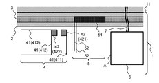
- FIG. 1 and 3 are plan views of a vehicle window glass according to an embodiment of the present invention as viewed from the inside of the vehicle.
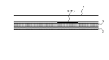
- FIG. 2 is a cross-sectional view of the vehicle window glass according to the first embodiment attached to a vehicle body. is there.
- the vehicle window glass 1 is attached to the vehicle body 2 of the vehicle with an adhesive 3.
- an antenna 4 a noise removal pattern 5, and an electronic device 6 are attached to the window glass 1.
- the antenna 4 is, for example, an antenna that receives a digital television broadcast wave, and a pattern and a power feeding unit that constitute an element are provided at a position near the upper side of the window glass.
- the electronic device 6 is provided on the window glass 1.
- the electronic device 6 emits noise during operation, and noise is also emitted from a cable connected to the electronic device 6. For this reason, it is desirable that the electronic device 6 and the cable 7 be arranged away from the antenna 4. However, since the electronic device 6 is for monitoring the front, the electronic device 6 and the cable 7 are provided on the front window glass 1. There are times when it must be close.
- the noise removal pattern 5 includes a wide first conductor 51 provided at a position hidden in the vehicle body 2 and one or a plurality of second conductors 52 extending downward from the first conductor 51. Including. Since the first conductor 51 is in contact with the vehicle body 2 via the adhesive layer 3, the first conductor 51 overlaps with the vehicle body 2 so as to be capacitively coupled to the vehicle body 2 and to have a ground potential in a high frequency (from the body flange 2). Provided on the vehicle body side).
- the adhesive 3 may be a non-conductive adhesive or a conductive adhesive.
- examples of a desired noise removal frequency band include a frequency band of 470 MHz to 710 MHz that can be used in digital television broadcasting, a frequency band of 174 MHz to 240 MHz that can be used in a broadcast stream of Digital Audio Broadcast, a GPS satellite wave, and the like.
- the frequency band of 1.2 GHz to 1.6 GHz, the ITS band such as ETC, the frequency band of 4 GHz to 6 GHz that can be used for inter-vehicle communication wave, 5G communication, and the like can be used.
- the vehicle window glass 1 according to the first embodiment is attached to the vehicle body 2 of the vehicle by an adhesive 3.
- the upper end of the window glass 1 is the line 11, and the leader line of the code
- an antenna 4, a noise removal pattern 5, and an electronic device 6 are attached to the window glass 1.
- the electronic device 6 is connected to an electronic circuit (for example, ECU) on the vehicle body side by a cable 7.
- the antenna 4 is, for example, an antenna that receives a digital television broadcast wave, and a pattern constituting the element 41 and a power feeding unit 42 are provided at a position near the upper side of the window glass.
- the power supply unit 42 includes a core wire side power supply unit 421 and a ground side power supply unit 422, and the element 41 includes a core wire side element 411 extending from the core wire side power supply unit 421, and a ground side element 412 extending from the ground side power supply unit 422. including.
- the core wire side element 411 is disposed on the electronic device 6 or the cable 7 (noise source) side, but the ground side element 412 may be disposed on the electronic device 6 or the cable 7 (noise source) side.
- . 1 shows an antenna that receives a digital TV broadcast wave as the antenna 4, but other radio waves (Digital Audio Broadcast broadcast wave, inter-vehicle communication wave, roadside communication wave, GPS satellite wave, etc.) May be received. Furthermore, an antenna for mobile communication such as a mobile phone may be used.
- the electronic device 6 is provided on the window glass 1.
- the electronic device 6 is, for example, a sensor (CCD camera, CMOS camera, near-infrared laser transmitter / receiver, ultrasonic transmitter / receiver, millimeter wave transmitter / receiver, etc.) for acquiring information outside the vehicle, and collision prevention to enhance safety. It is an electronic circuit of a system or a driving support system.
- the electronic device 6 is typically provided at the center on the left and right sides of the window glass 1 at a position of 50 mm to 200 mm from the upper body flange, but may be provided in the vicinity of the window glass 1.
- the cable 7 connected to the electronic device 6 typically extends upward so as not to obstruct the occupant's view.
- the noise removal pattern 5 includes a wide first conductor 51 provided at a position hidden in the vehicle body 2 and a first extension extending downward from the first conductor 51 (preferably in a direction substantially normal to the body flange 2). 2 conductors 52.
- the second conductor 52 is disposed so as to extend between the antenna 4 and the electronic device 6 or the cable 7. For this reason, the 2nd conductor 52 absorbs the noise which goes to the antenna 4 from the electronic device 6 or the cable 7, and the noise which arrives at the antenna 4 can be reduced.
- the first conductor 51 is preferably formed wide in order to increase the area disposed close to the vehicle body 2, but when the width of the first conductor 51 is widened, the resonance frequency decreases, It is necessary to shorten the length. Further, when the width of the first conductor 51 is widened, the Q value is lowered, so that the resonance is weakened, but the frequency range in which noise can be removed can be widened.
- the front surface of the first conductor 51 may be a conductor (a so-called solid pattern), or the filaments may be formed in a lattice shape or a mesh shape.
- the pitch of the grating is desirably ⁇ / 10 or less.
- the pitch of the grating is desirably 30 mm or less considering the upper limit frequency of 710 MHz in the digital television broadcast frequency band.
- the second conductor 52 may extend downward from the end of the first conductor 51 or may extend downward from the vicinity of the center of the first conductor 51. This increases the degree of freedom in the arrangement of the second conductor 52 with respect to the first conductor 51. In addition to the L-shape shown in the drawing, the degree of freedom of the shape such as a T-shape increases.
- the second conductor 52 may be disposed closer to the antenna 4 side, preferably in the vicinity of the antenna 4. That is, when the distance between the antenna 4 and the electronic device 6 and the distance between the antenna 4 and the cable 7 are divided into two equal parts, the second conductor 52 may be disposed at a position closer to the antenna than the bisection point. . It should be noted that the second conductor 52 may be arranged away from the element of the antenna 4 by a distance that does not operate as a director or a reflector. More specifically, assuming that the wavelength shortening rate of the glass is ⁇ , the noise removal pattern 5 is preferably disposed at a position of ⁇ / 10 to ⁇ / 4 from the feeding portion of the antenna 4.
- the noise removal pattern 5 may be arranged at a position of ⁇ / 10 to ⁇ / 4 from the side surface A of the electronic device 6 on the noise removal pattern 5 side or the cable 7.
- the noise removal pattern 5 is disposed in the vicinity of the noise source (electronic device 6 and cable 7)
- noise is easily absorbed by the second conductor 52 having a low potential, and a sufficient noise removal effect is obtained.
- the noise removal pattern 5 (first conductor 51) is provided on the window glass 1, that is, between the glass substrate 1 and the adhesive layer 3.
- the first conductor 51 Since the first conductor 51 is in contact with the vehicle body 2 via the adhesive layer 3, the first conductor 51 overlaps with the vehicle body 2 so as to be capacitively coupled to the vehicle body 2 and to have a ground potential in a high frequency (from the body flange 2). Provided on the vehicle body side). Note that the first conductor 51 and the vehicle body 2 may be connected in a direct current manner using a conductive adhesive. When a conductive adhesive is used for the adhesive 3, the size of the first conductor 51 and the characteristics of the adhesive 3 may be adjusted so that the contact resistance of the first conductor 51 is 50 ⁇ or less.
- the first conductor 51 When the first conductor 51 is provided at the position where the adhesive 3 is applied, the distance between the first conductor 51 and the vehicle body 2 is stabilized, and desired noise removal performance can be exhibited.
- the first conductor 51 may be provided between the application position of the adhesive 3 and the body flange 2, or may be provided between the application position of the adhesive 3 and the end portion 11 of the window glass 1. Good.
- the noise removal pattern 5 is formed on the surface of the window glass 1, but when the window glass 1 is made of laminated glass, the noise removal pattern 5 may be formed in the inner layer of the window glass 1.
- the conductors 51 and 51 of the noise removal pattern 5 are formed by printing a conductive ceramic paste on a glass surface with a predetermined width, and drying and baking in a heating furnace. Further, the conductors (wires and power feeding portions) constituting the antenna 4 are formed by printing the width of each wire with a conductive ceramic paste on a glass surface with a width of about 0.7 mm, and drying and baking in a heating furnace.
- the An antenna conductor may be formed by a conductive pattern formed on a light transmissive resin film, and the resin film may be attached to a glass plate.
- the noise removal pattern 5 is provided on the front window glass, but it may be provided on the rear window glass. Furthermore, if a device that becomes a noise source such as a sensor is mounted, a noise removal pattern may be provided on the side window glass.
- the noise removal pattern 5 desirably has a size that is 150 mm along the body flange 2 and within 150 mm in the normal direction of the body flange.
- the lengths of the first conductor 51 and the second conductor 52 are different depending on whether the adhesive 3 is conductive or non-conductive.
- the noise removal pattern 5 is not grounded in terms of direct current, and the end portion is a free end. Therefore, it is preferable to resonate at ⁇ / 2.
- the sum of the length of the first conductor 51 and the length of the second conductor 52 is calculated by calculating the length of the first conductor 51 as LA and the length of the second conductor 52 as LB.
- the lower limit wavelength of the desired noise removal frequency band is ⁇
- the wavelength shortening rate of the glass ⁇
- the wavelength shortening rate of the adhesive is ⁇ , which can be expressed by equation (2).
- LA / ( ⁇ ⁇ ⁇ ) + LB / ⁇ n ⁇ ⁇ / 2 (2)
- n is an arbitrary natural number. If the size of the noise removal pattern 5 is within a tolerance of about ⁇ 10% of the equation (1), there is no significant change in characteristics.
- the length of the 1st conductor 51 and the 2nd conductor 52 is the 2nd conductor 52 and the 1st conductor.
- the total length of the longer length from the connection position with the conductor 51 to the end of the first conductor 51 and the length of the second conductor 52 only needs to satisfy the above formula (1).
- the noise removal pattern 5 is grounded in the first conductor 51 (that is, one end of the pattern), so it is preferable to resonate at ⁇ / 4. That is, since the first conductor 51 is electrically connected to the vehicle body 2 and has the same potential, the first conductor 51 does not resonate at a high frequency and has no effect.
- the length of the second conductor 52 is preferably a length of ⁇ / 4 at the desired noise elimination frequency, and within a tolerance of about ⁇ 20%. There is no significant change in characteristics.
- the noise removal pattern 5 is configured to have frequency characteristics, a large amount of noise having a desired frequency can be absorbed.
- FIG. 3 is a plan view of the vehicle window glass according to the second embodiment as viewed from the vehicle inner side.
- differences from the first embodiment will be mainly described, and the same reference numerals as those of the components described in the first embodiment are given, and the description thereof will be omitted. Therefore, unless otherwise specified, the positional relationship of each component in the first embodiment is the same in the second embodiment.
- a plurality of second conductors 52 arranged substantially in parallel are provided.
- two second conductors 52 are provided, but three or more conductors may be provided, and may be appropriately adjusted in relation to noise removal characteristics.
- noise removal performance can be improved by providing a plurality of second conductors 52.
- the lengths of the plurality of second conductors 52 may be different. By making the length of the second conductor 52 different, the resonance frequency of the second conductor 52 is made different, and a noise removal effect can be obtained in a wide frequency band.
- the arrangement interval between the plurality of second conductors 52 is preferably about 5 to 10 mm. This is because a plurality of second conductors 52 are arranged close to each other and function as a single conductor when strongly coupled, while noise is eliminated when the plurality of second conductors 52 are arranged apart from each other. This is because the resonance relationship of the pattern 5 is broken and the noise removal effect is reduced in any case.
- FIG. 4 is a diagram showing the noise removal characteristics of the first embodiment.
- FIG. 4 shows the characteristics of the noise removal pattern of the first embodiment and the characteristics of variations in the digital television broadcast frequency band.
- the amount of noise attenuation becomes large in the vicinity of 520 MHz, and attenuation of ⁇ 4 dB or more on the low frequency side (470 to 600 MHz) of the digital television broadcasting frequency band. A quantity was obtained.
- the frequency (resonance frequency) with large noise attenuation changes to 620 MHz, 520 MHz, and 480 MHz, and the second conductor 52 becomes longer. Then, it can be seen that the frequency at which noise can be attenuated decreases. Further, it can be seen that as the second conductor 52 becomes longer, the resonance characteristic for attenuating the noise becomes dull and noise can be removed in a wide band.
Landscapes
- Details Of Aerials (AREA)
- Support Of Aerials (AREA)
Abstract
Priority Applications (4)
| Application Number | Priority Date | Filing Date | Title |
|---|---|---|---|
| US16/966,244 US11303007B2 (en) | 2018-03-22 | 2019-03-11 | Glass window for vehicle |
| JP2020508235A JP7212285B2 (ja) | 2018-03-22 | 2019-03-11 | 車両用窓ガラス |
| EP19771775.4A EP3771030A4 (fr) | 2018-03-22 | 2019-03-11 | Vitre en verre pour véhicule |
| CN201980012594.9A CN111699591B (zh) | 2018-03-22 | 2019-03-11 | 车辆用窗玻璃 |
Applications Claiming Priority (2)
| Application Number | Priority Date | Filing Date | Title |
|---|---|---|---|
| JP2018055322 | 2018-03-22 | ||
| JP2018-055322 | 2018-03-22 |
Publications (1)
| Publication Number | Publication Date |
|---|---|
| WO2019181623A1 true WO2019181623A1 (fr) | 2019-09-26 |
Family
ID=67987804
Family Applications (1)
| Application Number | Title | Priority Date | Filing Date |
|---|---|---|---|
| PCT/JP2019/009820 WO2019181623A1 (fr) | 2018-03-22 | 2019-03-11 | Vitre en verre pour véhicule |
Country Status (5)
| Country | Link |
|---|---|
| US (1) | US11303007B2 (fr) |
| EP (1) | EP3771030A4 (fr) |
| JP (1) | JP7212285B2 (fr) |
| CN (1) | CN111699591B (fr) |
| WO (1) | WO2019181623A1 (fr) |
Cited By (2)
| Publication number | Priority date | Publication date | Assignee | Title |
|---|---|---|---|---|
| WO2021015155A1 (fr) * | 2019-07-25 | 2021-01-28 | Agc株式会社 | Dispositif pour vitre de véhicule |
| DE102021006336A1 (de) | 2021-01-18 | 2022-07-21 | AGC Inc. | Antennenvorrichtung für ein fahrzeug |
Citations (9)
| Publication number | Priority date | Publication date | Assignee | Title |
|---|---|---|---|---|
| JP2000174529A (ja) * | 1998-12-07 | 2000-06-23 | Asahi Glass Co Ltd | 自動車用高周波ガラスアンテナ |
| JP2004260504A (ja) * | 2003-02-26 | 2004-09-16 | Yazaki Corp | 車両用アンテナ構造 |
| JP2007124235A (ja) * | 2005-10-27 | 2007-05-17 | Denso Corp | 放射ノイズの回り込み抑制方法 |
| WO2015019904A1 (fr) * | 2013-08-05 | 2015-02-12 | 旭硝子株式会社 | Dispositif d'antenne |
| JP2015095794A (ja) | 2013-11-13 | 2015-05-18 | セントラル硝子株式会社 | 自動車用窓ガラス及び自動車 |
| JP2016063416A (ja) | 2014-09-18 | 2016-04-25 | 本田技研工業株式会社 | ノイズ除去機構 |
| WO2018000503A1 (fr) * | 2016-06-30 | 2018-01-04 | 宇龙计算机通信科技(深圳)有限公司 | Procédé et dispositif de réglage de luminosité de rétroéclairage lcd de terminal, et terminal |
| JP2018055322A (ja) | 2016-09-28 | 2018-04-05 | 日立オートモティブシステムズ株式会社 | 画像処理装置、撮像装置 |
| WO2018079415A1 (fr) * | 2016-10-25 | 2018-05-03 | 日本板硝子株式会社 | Verre pour vitrage |
Family Cites Families (13)
| Publication number | Priority date | Publication date | Assignee | Title |
|---|---|---|---|---|
| US6118410A (en) * | 1999-07-29 | 2000-09-12 | General Motors Corporation | Automobile roof antenna shelf |
| TW554566B (en) * | 2002-05-01 | 2003-09-21 | Accton Technology Corp | Integrated dual-band printed monopole antenna |
| US6919848B2 (en) * | 2002-06-25 | 2005-07-19 | Harada Industry Co., Ltd. | Antenna apparatus for vehicle |
| JP2005130415A (ja) | 2003-10-27 | 2005-05-19 | Central Glass Co Ltd | 車両用ガラスアンテナ |
| GB0922191D0 (en) * | 2009-12-21 | 2010-02-03 | Pilkington Group Ltd | Vehicle glazing |
| JP5720308B2 (ja) | 2010-06-16 | 2015-05-20 | セントラル硝子株式会社 | 車両用ガラスアンテナ |
| CN105409057A (zh) * | 2013-07-31 | 2016-03-16 | 旭硝子株式会社 | 天线装置 |
| CN104347959A (zh) * | 2013-08-09 | 2015-02-11 | 无锡村田电子有限公司 | 天线装置 |
| EP3086476B8 (fr) * | 2013-12-20 | 2019-07-24 | AGC Inc. | Système d'antennes |
| CN105703076A (zh) * | 2014-11-24 | 2016-06-22 | 宏碁股份有限公司 | 移动装置 |
| JP6696502B2 (ja) * | 2015-05-21 | 2020-05-20 | Agc株式会社 | 車両用窓ガラス及びアンテナ |
| CN106558752A (zh) | 2015-09-28 | 2017-04-05 | 启碁科技股份有限公司 | 天线系统 |
| JP6661494B2 (ja) * | 2016-08-30 | 2020-03-11 | 株式会社デンソーテン | アンテナ装置 |
-
2019
- 2019-03-11 EP EP19771775.4A patent/EP3771030A4/fr not_active Withdrawn
- 2019-03-11 US US16/966,244 patent/US11303007B2/en active Active
- 2019-03-11 JP JP2020508235A patent/JP7212285B2/ja active Active
- 2019-03-11 WO PCT/JP2019/009820 patent/WO2019181623A1/fr active Application Filing
- 2019-03-11 CN CN201980012594.9A patent/CN111699591B/zh active Active
Patent Citations (9)
| Publication number | Priority date | Publication date | Assignee | Title |
|---|---|---|---|---|
| JP2000174529A (ja) * | 1998-12-07 | 2000-06-23 | Asahi Glass Co Ltd | 自動車用高周波ガラスアンテナ |
| JP2004260504A (ja) * | 2003-02-26 | 2004-09-16 | Yazaki Corp | 車両用アンテナ構造 |
| JP2007124235A (ja) * | 2005-10-27 | 2007-05-17 | Denso Corp | 放射ノイズの回り込み抑制方法 |
| WO2015019904A1 (fr) * | 2013-08-05 | 2015-02-12 | 旭硝子株式会社 | Dispositif d'antenne |
| JP2015095794A (ja) | 2013-11-13 | 2015-05-18 | セントラル硝子株式会社 | 自動車用窓ガラス及び自動車 |
| JP2016063416A (ja) | 2014-09-18 | 2016-04-25 | 本田技研工業株式会社 | ノイズ除去機構 |
| WO2018000503A1 (fr) * | 2016-06-30 | 2018-01-04 | 宇龙计算机通信科技(深圳)有限公司 | Procédé et dispositif de réglage de luminosité de rétroéclairage lcd de terminal, et terminal |
| JP2018055322A (ja) | 2016-09-28 | 2018-04-05 | 日立オートモティブシステムズ株式会社 | 画像処理装置、撮像装置 |
| WO2018079415A1 (fr) * | 2016-10-25 | 2018-05-03 | 日本板硝子株式会社 | Verre pour vitrage |
Non-Patent Citations (1)
| Title |
|---|
| See also references of EP3771030A4 |
Cited By (2)
| Publication number | Priority date | Publication date | Assignee | Title |
|---|---|---|---|---|
| WO2021015155A1 (fr) * | 2019-07-25 | 2021-01-28 | Agc株式会社 | Dispositif pour vitre de véhicule |
| DE102021006336A1 (de) | 2021-01-18 | 2022-07-21 | AGC Inc. | Antennenvorrichtung für ein fahrzeug |
Also Published As
| Publication number | Publication date |
|---|---|
| CN111699591B (zh) | 2022-06-07 |
| US20210050646A1 (en) | 2021-02-18 |
| JPWO2019181623A1 (ja) | 2021-03-25 |
| EP3771030A4 (fr) | 2021-12-08 |
| EP3771030A1 (fr) | 2021-01-27 |
| US11303007B2 (en) | 2022-04-12 |
| JP7212285B2 (ja) | 2023-01-25 |
| CN111699591A (zh) | 2020-09-22 |
Similar Documents
| Publication | Publication Date | Title |
|---|---|---|
| CN107453047B (zh) | 具有分段表面处理的双频带柔性天线 | |
| EP2660930A1 (fr) | Antenne | |
| JP6323455B2 (ja) | アンテナ装置 | |
| JP2008135944A (ja) | 自動車用高周波ガラスアンテナ及び窓ガラス板 | |
| US7321338B2 (en) | On-board antenna | |
| JP5115359B2 (ja) | 車両用ガラスアンテナ及び車両用窓ガラス板 | |
| WO2019181623A1 (fr) | Vitre en verre pour véhicule | |
| WO2019156138A1 (fr) | Dispositif d'antenne monté sur véhicule | |
| JP2005012588A (ja) | 車両用ガラスアンテナ装置 | |
| JP4114430B2 (ja) | アンテナ | |
| JP2011091557A (ja) | アンテナ装置 | |
| JP2008022538A (ja) | 自動車用高周波ガラスアンテナ | |
| WO2021015155A1 (fr) | Dispositif pour vitre de véhicule | |
| JP2008278481A (ja) | 自動車用高周波ガラスアンテナ及び自動車用の窓ガラス板 | |
| JP4788333B2 (ja) | 車両用ガラスアンテナ | |
| JPH11330847A (ja) | アンテナ装置 | |
| US7663563B2 (en) | High frequency wave glass antenna for an automobile and window glass sheet for an automobile with the same | |
| JP3833609B2 (ja) | 車載アンテナ | |
| JP5631238B2 (ja) | ガラスアンテナ及び窓ガラス、並びにそれらを備えるアンテナ装置 | |
| WO2020230696A1 (fr) | Dispositif d'antenne | |
| JP2007110390A (ja) | 自動車用高周波ガラスアンテナ | |
| JP2008278447A (ja) | 自動車用高周波ガラスアンテナ及び自動車用の窓ガラス板 | |
| JP2011172281A (ja) | 車両用ガラスアンテナ形成用部品 | |
| JP2002368514A (ja) | 車両用ガラスアンテナ装置 | |
| WO2023058678A1 (fr) | Dispositif d'antennes de véhicule |
Legal Events
| Date | Code | Title | Description |
|---|---|---|---|
| 121 | Ep: the epo has been informed by wipo that ep was designated in this application |
Ref document number: 19771775 Country of ref document: EP Kind code of ref document: A1 |
|
| ENP | Entry into the national phase |
Ref document number: 2020508235 Country of ref document: JP Kind code of ref document: A |
|
| NENP | Non-entry into the national phase |
Ref country code: DE |
|
| WWE | Wipo information: entry into national phase |
Ref document number: 2019771775 Country of ref document: EP |
|
| ENP | Entry into the national phase |
Ref document number: 2019771775 Country of ref document: EP Effective date: 20201022 |