WO2019181241A1 - ストッカシステム - Google Patents
ストッカシステム Download PDFInfo
- Publication number
- WO2019181241A1 WO2019181241A1 PCT/JP2019/003837 JP2019003837W WO2019181241A1 WO 2019181241 A1 WO2019181241 A1 WO 2019181241A1 JP 2019003837 W JP2019003837 W JP 2019003837W WO 2019181241 A1 WO2019181241 A1 WO 2019181241A1
- Authority
- WO
- WIPO (PCT)
- Prior art keywords
- article
- crane
- ceiling
- track
- shelves
- Prior art date
Links
Images


Classifications
-
- H—ELECTRICITY
- H01—ELECTRIC ELEMENTS
- H01L—SEMICONDUCTOR DEVICES NOT COVERED BY CLASS H10
- H01L21/00—Processes or apparatus adapted for the manufacture or treatment of semiconductor or solid state devices or of parts thereof
- H01L21/67—Apparatus specially adapted for handling semiconductor or electric solid state devices during manufacture or treatment thereof; Apparatus specially adapted for handling wafers during manufacture or treatment of semiconductor or electric solid state devices or components ; Apparatus not specifically provided for elsewhere
- H01L21/677—Apparatus specially adapted for handling semiconductor or electric solid state devices during manufacture or treatment thereof; Apparatus specially adapted for handling wafers during manufacture or treatment of semiconductor or electric solid state devices or components ; Apparatus not specifically provided for elsewhere for conveying, e.g. between different workstations
- H01L21/67703—Apparatus specially adapted for handling semiconductor or electric solid state devices during manufacture or treatment thereof; Apparatus specially adapted for handling wafers during manufacture or treatment of semiconductor or electric solid state devices or components ; Apparatus not specifically provided for elsewhere for conveying, e.g. between different workstations between different workstations
- H01L21/67733—Overhead conveying
-
- B—PERFORMING OPERATIONS; TRANSPORTING
- B65—CONVEYING; PACKING; STORING; HANDLING THIN OR FILAMENTARY MATERIAL
- B65G—TRANSPORT OR STORAGE DEVICES, e.g. CONVEYORS FOR LOADING OR TIPPING, SHOP CONVEYOR SYSTEMS OR PNEUMATIC TUBE CONVEYORS
- B65G1/00—Storing articles, individually or in orderly arrangement, in warehouses or magazines
- B65G1/02—Storage devices
- B65G1/04—Storage devices mechanical
-
- H—ELECTRICITY
- H01—ELECTRIC ELEMENTS
- H01L—SEMICONDUCTOR DEVICES NOT COVERED BY CLASS H10
- H01L21/00—Processes or apparatus adapted for the manufacture or treatment of semiconductor or solid state devices or of parts thereof
- H01L21/67—Apparatus specially adapted for handling semiconductor or electric solid state devices during manufacture or treatment thereof; Apparatus specially adapted for handling wafers during manufacture or treatment of semiconductor or electric solid state devices or components ; Apparatus not specifically provided for elsewhere
- H01L21/677—Apparatus specially adapted for handling semiconductor or electric solid state devices during manufacture or treatment thereof; Apparatus specially adapted for handling wafers during manufacture or treatment of semiconductor or electric solid state devices or components ; Apparatus not specifically provided for elsewhere for conveying, e.g. between different workstations
- H01L21/67703—Apparatus specially adapted for handling semiconductor or electric solid state devices during manufacture or treatment thereof; Apparatus specially adapted for handling wafers during manufacture or treatment of semiconductor or electric solid state devices or components ; Apparatus not specifically provided for elsewhere for conveying, e.g. between different workstations between different workstations
- H01L21/67736—Loading to or unloading from a conveyor
-
- B—PERFORMING OPERATIONS; TRANSPORTING
- B65—CONVEYING; PACKING; STORING; HANDLING THIN OR FILAMENTARY MATERIAL
- B65G—TRANSPORT OR STORAGE DEVICES, e.g. CONVEYORS FOR LOADING OR TIPPING, SHOP CONVEYOR SYSTEMS OR PNEUMATIC TUBE CONVEYORS
- B65G1/00—Storing articles, individually or in orderly arrangement, in warehouses or magazines
- B65G1/02—Storage devices
- B65G1/04—Storage devices mechanical
- B65G1/0457—Storage devices mechanical with suspended load carriers
-
- B—PERFORMING OPERATIONS; TRANSPORTING
- B65—CONVEYING; PACKING; STORING; HANDLING THIN OR FILAMENTARY MATERIAL
- B65G—TRANSPORT OR STORAGE DEVICES, e.g. CONVEYORS FOR LOADING OR TIPPING, SHOP CONVEYOR SYSTEMS OR PNEUMATIC TUBE CONVEYORS
- B65G1/00—Storing articles, individually or in orderly arrangement, in warehouses or magazines
- B65G1/02—Storage devices
- B65G1/04—Storage devices mechanical
- B65G1/0464—Storage devices mechanical with access from above
-
- B—PERFORMING OPERATIONS; TRANSPORTING
- B65—CONVEYING; PACKING; STORING; HANDLING THIN OR FILAMENTARY MATERIAL
- B65G—TRANSPORT OR STORAGE DEVICES, e.g. CONVEYORS FOR LOADING OR TIPPING, SHOP CONVEYOR SYSTEMS OR PNEUMATIC TUBE CONVEYORS
- B65G1/00—Storing articles, individually or in orderly arrangement, in warehouses or magazines
- B65G1/02—Storage devices
- B65G1/04—Storage devices mechanical
- B65G1/06—Storage devices mechanical with means for presenting articles for removal at predetermined position or level
-
- B—PERFORMING OPERATIONS; TRANSPORTING
- B66—HOISTING; LIFTING; HAULING
- B66F—HOISTING, LIFTING, HAULING OR PUSHING, NOT OTHERWISE PROVIDED FOR, e.g. DEVICES WHICH APPLY A LIFTING OR PUSHING FORCE DIRECTLY TO THE SURFACE OF A LOAD
- B66F9/00—Devices for lifting or lowering bulky or heavy goods for loading or unloading purposes
- B66F9/06—Devices for lifting or lowering bulky or heavy goods for loading or unloading purposes movable, with their loads, on wheels or the like, e.g. fork-lift trucks
- B66F9/075—Constructional features or details
- B66F9/12—Platforms; Forks; Other load supporting or gripping members
- B66F9/14—Platforms; Forks; Other load supporting or gripping members laterally movable, e.g. swingable, for slewing or transverse movements
-
- H—ELECTRICITY
- H01—ELECTRIC ELEMENTS
- H01L—SEMICONDUCTOR DEVICES NOT COVERED BY CLASS H10
- H01L21/00—Processes or apparatus adapted for the manufacture or treatment of semiconductor or solid state devices or of parts thereof
- H01L21/67—Apparatus specially adapted for handling semiconductor or electric solid state devices during manufacture or treatment thereof; Apparatus specially adapted for handling wafers during manufacture or treatment of semiconductor or electric solid state devices or components ; Apparatus not specifically provided for elsewhere
- H01L21/673—Apparatus specially adapted for handling semiconductor or electric solid state devices during manufacture or treatment thereof; Apparatus specially adapted for handling wafers during manufacture or treatment of semiconductor or electric solid state devices or components ; Apparatus not specifically provided for elsewhere using specially adapted carriers or holders; Fixing the workpieces on such carriers or holders
-
- H—ELECTRICITY
- H01—ELECTRIC ELEMENTS
- H01L—SEMICONDUCTOR DEVICES NOT COVERED BY CLASS H10
- H01L21/00—Processes or apparatus adapted for the manufacture or treatment of semiconductor or solid state devices or of parts thereof
- H01L21/67—Apparatus specially adapted for handling semiconductor or electric solid state devices during manufacture or treatment thereof; Apparatus specially adapted for handling wafers during manufacture or treatment of semiconductor or electric solid state devices or components ; Apparatus not specifically provided for elsewhere
- H01L21/677—Apparatus specially adapted for handling semiconductor or electric solid state devices during manufacture or treatment thereof; Apparatus specially adapted for handling wafers during manufacture or treatment of semiconductor or electric solid state devices or components ; Apparatus not specifically provided for elsewhere for conveying, e.g. between different workstations
- H01L21/67703—Apparatus specially adapted for handling semiconductor or electric solid state devices during manufacture or treatment thereof; Apparatus specially adapted for handling wafers during manufacture or treatment of semiconductor or electric solid state devices or components ; Apparatus not specifically provided for elsewhere for conveying, e.g. between different workstations between different workstations
- H01L21/67706—Mechanical details, e.g. roller, belt
-
- H—ELECTRICITY
- H01—ELECTRIC ELEMENTS
- H01L—SEMICONDUCTOR DEVICES NOT COVERED BY CLASS H10
- H01L21/00—Processes or apparatus adapted for the manufacture or treatment of semiconductor or solid state devices or of parts thereof
- H01L21/67—Apparatus specially adapted for handling semiconductor or electric solid state devices during manufacture or treatment thereof; Apparatus specially adapted for handling wafers during manufacture or treatment of semiconductor or electric solid state devices or components ; Apparatus not specifically provided for elsewhere
- H01L21/677—Apparatus specially adapted for handling semiconductor or electric solid state devices during manufacture or treatment thereof; Apparatus specially adapted for handling wafers during manufacture or treatment of semiconductor or electric solid state devices or components ; Apparatus not specifically provided for elsewhere for conveying, e.g. between different workstations
- H01L21/67703—Apparatus specially adapted for handling semiconductor or electric solid state devices during manufacture or treatment thereof; Apparatus specially adapted for handling wafers during manufacture or treatment of semiconductor or electric solid state devices or components ; Apparatus not specifically provided for elsewhere for conveying, e.g. between different workstations between different workstations
- H01L21/67724—Apparatus specially adapted for handling semiconductor or electric solid state devices during manufacture or treatment thereof; Apparatus specially adapted for handling wafers during manufacture or treatment of semiconductor or electric solid state devices or components ; Apparatus not specifically provided for elsewhere for conveying, e.g. between different workstations between different workstations by means of a cart or a vehicule
-
- H—ELECTRICITY
- H01—ELECTRIC ELEMENTS
- H01L—SEMICONDUCTOR DEVICES NOT COVERED BY CLASS H10
- H01L21/00—Processes or apparatus adapted for the manufacture or treatment of semiconductor or solid state devices or of parts thereof
- H01L21/67—Apparatus specially adapted for handling semiconductor or electric solid state devices during manufacture or treatment thereof; Apparatus specially adapted for handling wafers during manufacture or treatment of semiconductor or electric solid state devices or components ; Apparatus not specifically provided for elsewhere
- H01L21/677—Apparatus specially adapted for handling semiconductor or electric solid state devices during manufacture or treatment thereof; Apparatus specially adapted for handling wafers during manufacture or treatment of semiconductor or electric solid state devices or components ; Apparatus not specifically provided for elsewhere for conveying, e.g. between different workstations
- H01L21/67703—Apparatus specially adapted for handling semiconductor or electric solid state devices during manufacture or treatment thereof; Apparatus specially adapted for handling wafers during manufacture or treatment of semiconductor or electric solid state devices or components ; Apparatus not specifically provided for elsewhere for conveying, e.g. between different workstations between different workstations
- H01L21/6773—Conveying cassettes, containers or carriers
-
- H—ELECTRICITY
- H01—ELECTRIC ELEMENTS
- H01L—SEMICONDUCTOR DEVICES NOT COVERED BY CLASS H10
- H01L21/00—Processes or apparatus adapted for the manufacture or treatment of semiconductor or solid state devices or of parts thereof
- H01L21/67—Apparatus specially adapted for handling semiconductor or electric solid state devices during manufacture or treatment thereof; Apparatus specially adapted for handling wafers during manufacture or treatment of semiconductor or electric solid state devices or components ; Apparatus not specifically provided for elsewhere
- H01L21/677—Apparatus specially adapted for handling semiconductor or electric solid state devices during manufacture or treatment thereof; Apparatus specially adapted for handling wafers during manufacture or treatment of semiconductor or electric solid state devices or components ; Apparatus not specifically provided for elsewhere for conveying, e.g. between different workstations
- H01L21/67763—Apparatus specially adapted for handling semiconductor or electric solid state devices during manufacture or treatment thereof; Apparatus specially adapted for handling wafers during manufacture or treatment of semiconductor or electric solid state devices or components ; Apparatus not specifically provided for elsewhere for conveying, e.g. between different workstations the wafers being stored in a carrier, involving loading and unloading
- H01L21/67769—Storage means
-
- B—PERFORMING OPERATIONS; TRANSPORTING
- B65—CONVEYING; PACKING; STORING; HANDLING THIN OR FILAMENTARY MATERIAL
- B65G—TRANSPORT OR STORAGE DEVICES, e.g. CONVEYORS FOR LOADING OR TIPPING, SHOP CONVEYOR SYSTEMS OR PNEUMATIC TUBE CONVEYORS
- B65G2201/00—Indexing codes relating to handling devices, e.g. conveyors, characterised by the type of product or load being conveyed or handled
- B65G2201/02—Articles
- B65G2201/0297—Wafer cassette
-
- B—PERFORMING OPERATIONS; TRANSPORTING
- B66—HOISTING; LIFTING; HAULING
- B66C—CRANES; LOAD-ENGAGING ELEMENTS OR DEVICES FOR CRANES, CAPSTANS, WINCHES, OR TACKLES
- B66C19/00—Cranes comprising trolleys or crabs running on fixed or movable bridges or gantries
- B66C19/005—Straddle carriers
Definitions
- the present invention relates to a stocker system.
- a stocker for storing articles such as a FOUP that accommodates a semiconductor wafer or a reticle Pod that accommodates a reticle is provided.
- the stocker includes a plurality of shelves installed on the floor of the building and a crane that moves along the shelves (see, for example, Patent Document 1).
- the plurality of shelves are provided in the vertical and horizontal directions, and a storage shelf on which an article can be placed by a crane and a ceiling transport vehicle that travels along a track laid on or near the ceiling is used to drop and place the article.
- a loading / unloading port The crane transfers articles between the storage shelf and the loading / unloading port.
- Patent Document 1 The stocker described in Patent Document 1 has a plurality of shelves installed on the floor surface of the building, and the crane travels along a track laid on the floor surface. It is necessary to secure space on the floor.
- the present invention can improve the storage efficiency of articles by storing a plurality of articles at a high density while eliminating the area required for the installation of the stocker on the floor of the building by installing the stocker upward.
- An object is to provide a stocker system.
- the present invention has a stocker capable of storing an article conveyed by a ceiling conveyance vehicle, and the ceiling conveyance vehicle includes a gripping part for grasping an upper part of the article from the upper side, and an elevating drive part for raising and lowering the gripping part,
- a stocker system that travels on a track laid on the ceiling of the building and places items on a load port of a device installed below the track.
- the stocker is disposed above the device and is vertically oriented.
- the shelf is the loading / unloading port
- the crane is provided with a transfer device for loading and placing articles on the entry / exit ports or storage shelves.
- a stocker system is provided in which an article placed at a storage / reception port is placed on a storage shelf, or an article placed on a storage shelf is taken out and placed at a storage / reception port.
- the track is located directly above the load port, the loading / unloading port is disposed below and on the side of the track, and the overhead transportation vehicle causes the lifting drive unit to run sideways to the side of the track. It is also possible to have a configuration in which the article is lowered and placed in the entry / exit port by taking out the lift drive part by the side take-out mechanism and lowering the gripping part, or receiving the article placed in the entry / exit port.
- the storage shelves may be provided in multiple stages on at least one of the upper side and the lower side of the loading / unloading port.
- the loading / unloading port is located directly under the track, and the overhead transportation vehicle has a laterally extending mechanism that laterally moves the lifting / lowering drive part to the side of the track.
- the configuration may be such that the article is lowered and placed on the load port by lowering the part, or the article placed on the load port is received.
- the storage shelves may be provided in multiple stages below the loading / unloading port.
- the crane may travel on a circular track, and the plurality of shelves may be provided corresponding to a straight section in the circular track.
- item may be provided in the other side on both sides of the traveling area of a crane with respect to the loading / unloading port.
- the stocker since the stocker is arranged above the apparatus, it can be realized without installing a large-capacity stocker on the floor surface that allows goods to be loaded and unloaded by the ceiling transport vehicle.
- a part of the floor of the building can be used for purposes other than the stocker installation, for example, the space below the stocker can be used as a worker passage.
- the vertical dimension of the storage shelf is smaller than the loading / unloading port, the vertical dimension can be suppressed even if the storage rack is multi-staged. As a result, by storing articles in this storage shelf, a plurality of articles can be stored at high density, and the efficiency of storing articles can be improved.
- the track is located immediately above the load port, the loading / unloading port is disposed below and to the side of the track, and the overhead transportation vehicle causes the elevating drive unit to run sideways to the track.
- the overhead transportation vehicle causes the elevating drive unit to run sideways to the track.
- the vertical dimension of the storage shelf is smaller than the entry / exit port, so by increasing the number of stages of the storage shelf, Goods can be stored at high density.
- the loading / unloading port is located directly under the track, and the overhead transportation vehicle has a horizontal drive mechanism that moves the lift drive part to the side of the track.
- the entry / exit port is arranged directly below the track, so the overhead transport vehicle lowers the gripping part.
- the goods can be delivered to the loading / unloading port simply by making them.
- articles can be stored at a high density by increasing the number of storage shelves whose vertical dimension is smaller than that of the entry / exit port.
- the crane can easily rotate so that the crane can be easily positioned on one of the plurality of shelves. Furthermore, since a plurality of shelves are provided in the straight section, the installation and structure of the shelves are simplified and the cost can be reduced. Further, in a configuration in which a second storage shelf is provided on the opposite side of the crane travel region with respect to the loading / unloading port, the article can be placed in the second storage shelf. By making it possible, a large-capacity stocker can be realized.
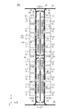
- FIG. 1 is a diagram of an example of a stocker system SYS according to the first embodiment viewed from the Y direction.
- FIG. 2 is a diagram schematically showing the stocker system SYS in plan view.
- the stocker system SYS shown in FIGS. 1 and 2 is provided in a semiconductor device manufacturing factory or the like, for example, an article 2 such as a FOUP containing a semiconductor wafer used for manufacturing a semiconductor device or a reticle pod containing a reticle or the like. Keep.
- the stocker system SYS is provided so as to be connected to a transport system for transporting the article 2.
- the article 2 is a FOUP will be described, but the article 2 may be other than the FOUP.
- the stocker system SYS can be applied to facilities other than the semiconductor manufacturing field, and the article 2 may be another article that can be stored in the stocker system SYS.
- the stocker system SYS includes a stocker 100 as shown in FIGS.
- the stocker 100 includes a plurality of shelves 10, a crane overhead track 20, and a crane 40.
- the plurality of shelves 10 are provided inside a circular ceiling track (track) 30 on which the ceiling transport vehicle 50 travels in a plan view, and between the crane ceiling track 20 and the circular ceiling track 30. Placed in.
- the plurality of shelves 10 are held by a frame 13 and arranged in four stages in the vertical direction (Z direction).
- the plurality of shelves 10 are arranged side by side along the traveling direction (Y direction) of the crane 40 described later.
- the shelf 10 is used in the meaning of a space where the article 2 is placed and stored, or a storage space.
- the shelf 10 is an article in which a surface on which the article 2 is placed (for example, the upper surface of the shelf boards 11a and 12a) and a space from this surface to an upper ceiling or the like (for example, the lower surface of the shelf boards 11a and 12a). 2 storage space or storage space.
- the plurality of shelves 10 each include a storage shelf 11 on which the article 2 is placed and an entry / exit port 12.
- Each of the storage shelf 11 and the loading / unloading port 12 includes shelf plates 11a and 12a on which the articles 2 are placed. From the upper surface of the shelf plates 11a and 12a to the lower surface of the upper shelf plate 11a and the like. Has vertical dimensions.
- placing the article 2 on the storage shelf 11 or the entry / exit port 12 means placing the article 2 on the shelf board 11 a of the storage shelf 11 or the shelf board 12 a of the entry / exit port 12.
- shelf plates 11 a and 12 a of the storage shelf 11 and the loading / unloading port 12 may be provided with a plurality of pins that enter the groove portions provided on the bottom surface of the article 2 when the article 2 is placed. When the pins enter the groove portion of the article 2, the article 2 is positioned with respect to the storage shelf 11 or the entry / exit port 12.
- the plurality of shelves 10 are provided in a state of being suspended from the system ceiling SC1 by the frame 13.
- the system ceiling SC1 is arranged in a state of being suspended from the ceiling C of the building by the hanging metal fittings 3.
- the frame 13 may be suspended from the ceiling C instead of being suspended from the system ceiling SC1.
- the height from the floor surface F is set to height H1.
- the height H1 is set to be higher than the height H2 of the processing device TL from the floor surface F.
- the height H3 of the lower end of the crane 40 mentioned later is also set so that it may become higher than the height H2 of the processing apparatus TL. That is, the stocker 100 is disposed above the processing device TL.
- height H3 may ensure the height for forming the channel
- the plurality of shelves 10 include upper and lower three-stage storage shelves 11 and a lowermost loading / unloading port 12 arranged below the storage shelves 11.
- the number of steps of the storage shelf 11 can be arbitrarily set. For example, four or more steps may be provided above the loading / unloading port 12. Further, the storage shelves 11 may be provided in multiple stages below the loading / unloading port 12 if there is an installation space.
- the entry / exit port 12 is a port for delivering the article 2 to / from the ceiling transport vehicle 50 traveling on the circular ceiling track 30. Although the entry / exit port 12 of this embodiment is arrange
- the entry / exit port 12 is set according to the height of the ceiling transport vehicle 50 that travels on the circular ceiling track 30. Therefore, for example, by changing the height of the ceiling conveyance vehicle 50, the loading / unloading port 12 can be set at the middle or uppermost level other than the lowermost level.
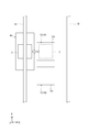
- FIG. 3 is a view of the storage shelf 11 and the entry / exit port 12 as seen from the X direction.
- the frames 13 of the plurality of shelves 10 are omitted.
- the entry / exit port 12 is arranged at the lowest level in the vertical direction among the plurality of shelves 10.
- the entry / exit ports 12 are illustrated at both ends of the traveling direction (Y direction) of the crane 40, but the lowest stage of the plurality of shelves 10 is the entry / exit port 12.
- a part of the lowermost stage of the plurality of shelves 10 may be the storage shelf 11. Both the crane 40 and the overhead conveyance vehicle 50 can deliver the article 2 to the entry / exit port 12. As shown in FIG.
- the entry / exit port 12 is provided to have a vertical dimension (length in the vertical direction) L1.
- the vertical dimension L1 is a dimension necessary for raising and lowering the article 2 by part of the gripping part 53, the raising / lowering driving part 54, and the lateral feeding mechanism 55 of the ceiling transport vehicle 50 described later entering the upper side of the loading / unloading port 12. It is.
- the storage shelf 11 cannot deliver the article 2 by the overhead conveyance vehicle 50, and delivers the article 2 by the crane 40.
- the storage shelf 11 is provided so as to have a vertical dimension L2.
- the vertical dimension L2 of the storage shelf 11 is smaller than the vertical dimension L1 of the loading / unloading port 12.
- the vertical dimension L2 is a dimension necessary for the transfer device 42 of the crane 40 described later to lift the article 2. Since the transfer device 42 of the crane 40 is configured to lift a part of the article 2, a large space is not required above the article 2.
- the vertical dimension L ⁇ b> 2 can be a dimension that adds several centimeters to the vertical dimension of the article 2.
- the storage shelf 11 has the vertical dimension L2 and is smaller than the vertical dimension L1, the ceiling C (or system ceiling) of the building when the stocker 100 (the plurality of shelves 10) is arranged above the processing device TL. Even if the space up to SC1 etc. is limited, the storage shelf 11 can be provided in multiple stages in the vertical direction efficiently in this space. As a result, the plurality of articles 2 can be stored in the plurality of shelves 10 with high density, and the storage efficiency of the articles 2 can be improved.
- the crane overhead track 20 is provided in a state of being suspended from the system ceiling SC ⁇ b> 1 by the suspension fitting 5.
- the crane ceiling track 20 may be suspended from the ceiling C instead of being suspended from the system ceiling SC1.
- the crane ceiling track 20 is a linear track extending in the Y direction, and is provided in a range that fits inside the orbiting ceiling track 30 in plan view. That is, the crane ceiling track 20 is not partially extended to the outside of the orbiting ceiling track 30 in plan view, or the crane 40 traveling on the crane ceiling track 20 moves to the outside of the orbiting ceiling track 30. It is in a form that cannot be done. Therefore, the + Y side and ⁇ Y side ends of the crane ceiling track 20 are arranged inside the orbiting ceiling track 30 in a plan view, and the track between the ends is also inside the orbiting ceiling track 30 in a plan view. Placed in.
- the crane ceiling track 20 is a straight track, even if the range inside the orbiting ceiling track 30 in a plan view is narrow, the crane ceiling track 20 can be within the range (or a part of the track can be arranged in the orbiting ceiling).
- the crane overhead track 20 and the crane 40 can be installed (so that they are not located outside the track 30).
- the crane ceiling track 20 is different in height from the floor surface F with respect to the circulating ceiling track 30.
- the crane ceiling track 20 has a higher height from the floor surface F than the circulating ceiling track 30.
- the crane ceiling track 20 may be lower in height from the floor surface F than the circulating ceiling track 30 or may be the same height as the circulating ceiling track 30.
- the crane 40 travels on the crane overhead track 20 and moves while holding the article 2.
- the crane 40 transfers the article 2 between the storage shelf 11 and another storage shelf 11 or between the storage shelf 11 and the loading / unloading port 12.
- the crane 40 can travel in the + Y direction and the ⁇ Y direction on the crane ceiling track 20 and can reciprocate.
- positioned at one overhead track 20 for cranes is not limited to one.
- two or more cranes 40 may be disposed on one crane ceiling track 20.
- the crane 40 has a part of the orbiting ceiling track 30 and the overhead transport vehicle 50 in a side view (as viewed from the X direction or from a direction orthogonal to the traveling direction of the crane 40). It is provided at a height that overlaps either or both.
- the vertical dimension of the stocker 100 (the plurality of shelves 10) with respect to the orbiting ceiling track 30 can be suppressed, and the height H1 of the lower ends of the plurality of shelves 10 and the lower end of the mast 43 of the crane 40 can be reduced.
- the height H3 can be easily set to be equal to or higher than the height H2 of the processing apparatus TL.
- the crane 40 is provided in a state of being suspended from the traveling unit 41, and includes a transfer device 42 that delivers the article 2 to and from the storage shelf 11 or the loading / unloading port 12.
- the transfer device 42 has a mast 43.
- the mast 43 is provided such that the height of the lower end from the floor surface F is the height H3.
- the lower end of the mast 43 is the lower end of the crane 40, and the crane 40 has a height H3 from the floor surface F.
- the height H3 is higher than the height H1 of the processing apparatus TL as described above.
- FIG. 4 is a diagram illustrating an example of the crane 40.
- the crane 40 travels on the crane ceiling track 20 laid on the ceiling C side, so there is no need to provide a track on the floor F side (ground side).
- the crane 40 includes two traveling units 41 (see FIG. 3) and a transfer device 42. Below the traveling part 41, an upper support part 47 is attached via an attachment part 46, and the two traveling parts 41 are connected by the upper support part 47.
- Each traveling unit 41 includes a traveling drive unit (not shown) and a plurality of wheels 41 a, and travels along the crane overhead track 20.
- the travel drive unit may be, for example, an electric motor that is provided in the travel unit 41 and drives the wheels 41a, or may be a linear motor that is provided using the crane ceiling track 20.
- the transfer device 42 and the article 2 which are heavy objects can be reliably supported by using the two traveling units 41.
- the two traveling parts 41 are used for the crane 40, it is not limited to this structure, One or three or more traveling parts 41 may be used.
- the transfer device 42 includes a mast 43, an elevating table 44, an elevating drive unit 45, a telescopic unit 48, and a mounting table 49.
- the mast 43 extends in the vertical direction while being suspended from the upper support portion 47, and two masts 43 are provided before and after the traveling portion 41 in the traveling direction (see FIG. 3).
- the mast 43 is formed in a hollow or solid rod shape, and the cross section is formed in a polygonal shape such as a circular shape, an elliptical shape, an oval shape, or a rectangular shape.
- a fastening member such as a bolt and a nut may be used, or welding or the like may be used.
- the mast 43 may be one.
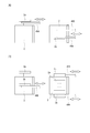
- FIG. 5 is a plan view showing an example of the transfer device 42 provided in the crane 40.
- the lifting table 44 of the transfer device 42 is arranged in a state of being sandwiched between two masts 43 and can be moved up and down by being guided by the mast 43.
- a transfer device 42 is attached to the upper surface side of the lifting platform 44.
- the lifting platform 44 includes a guide roller 44 a that comes into contact with the surface of the mast 43, and smoothly moves up and down along the mast 43.
- a lower support 47a is provided at the lower part of the mast 43 (see FIG. 3), and the lifting platform 44 can be lowered to a position where it comes into contact with the lower support 47a.
- the lower support portion 47 a prevents the lifting platform 44 from falling downward from the mast 43.
- the expansion / contraction part 48 includes a plurality of arms that can extend and contract in a direction orthogonal to the traveling direction of the traveling part 41.
- the mounting table 49 is provided at the tip of the extendable part 48.
- the mounting table 49 is a triangular plate member on which the article 2 can be mounted.
- the mounting table 49 holds the article 2 by placing the article 2 thereon.
- On the upper surface of the mounting table 49 a pin 49 a is provided for positioning the article 2 by being inserted into a groove provided on the bottom surface of the article 2.
- the storage shelf 11 and the loading / unloading port 12 are provided with a notch CU through which the mounting table 49 can pass in the vertical direction.
- the transfer device 42 When the transfer device 42 receives the article 2 from the storage shelf 11 or the loading / unloading port 12, it extends the telescopic part 48 and raises the lifting table 44 with the mounting table 49 positioned below the article 2. The article 2 is scooped up by the mounting table 49. Subsequently, the transfer device 42 places the mounting table 49 on which the article 2 is placed above the lifting table 44 by contracting the extendable part 48 while the article 2 is placed on the mounting table 49. Further, when the article 2 is transferred to the storage shelf 11 or the loading / unloading port 12 by the transfer device 42, the reverse operation is performed.
- the transfer device 42 is not limited to the configuration described above.
- FIG. 6 (A) and 6 (B) are diagrams showing other examples of the transfer device, respectively.
- a fork portion 49 ⁇ / b> A may be attached to the tip of the extendable portion 48 instead of the mounting table 49 described above.
- the fork portion 49A can enter below the flange portion 2a provided on the upper portion of the article 2 as the stretchable portion 48 extends.
- the lifting platform 44 see FIG. 5
- the article 2 in the storage shelf 11 or the loading / unloading port 12 can be lifted.
- goods 2 can be set
- a fork portion 49B may be attached to the tip of the extendable portion 48 instead of the mounting table 49 described above.
- the fork portion 49B can enter the lower side of the side flange portion 2b provided on the side surface of the article 2 as the stretchable portion 48 extends.
- the lifting platform 44 see FIG. 5
- the article 2 in the storage shelf 11 or the loading / unloading port 12 can be lifted.
- goods 2 can be set
- the elevating drive unit 45 uses, for example, a hoist or the like, and elevates the elevating table 44 along the mast 43.
- the raising / lowering drive part 45 is provided with the suspension member 45a and the drive part not shown.
- the suspension member 45a is, for example, a belt or a wire, and the lifting platform 44 is suspended from the upper support portion 47 by the suspension member 45a.
- a drive unit (not shown) is provided, for example, in the upper support unit 47, and feeds and winds the suspension member 45a.
- the elevator 44 is guided by the mast 43 and descends when the drive unit extends the suspension member 45a. Further, when the drive unit winds the suspension member 45a, the lifting platform 44 is guided by the mast 43 and rises.
- the elevating drive unit 45 is controlled by a control device (not shown) or the like to lower or elevate the elevating table 44 at a predetermined speed. Moreover, the raising / lowering drive part 45 is controlled by the control apparatus etc., and hold
- the elevating drive unit 45 is provided on the upper support unit 47 (running unit 41).
- the raising / lowering drive part 45 may be provided in the raising / lowering stand 44 instead of being provided in the upper support part 47, for example.
- the lifting / lowering platform 44 is provided with the lifting / lowering drive unit 45, for example, the lifting / lowering platform 44 is lifted / lowered by hoisting or feeding the belt or wire suspended from the upper support 47 with a hoist mounted on the lifting / lowering platform 44. You may let them.
- an electric motor or the like for driving a pinion gear is mounted on the lifting / lowering base 44, and a rack that meshes with the pinion gear is formed on the mast 43, and the lifting / lowering base 44 is lifted / lowered by driving the electric motor or the like to rotate the pinion gear. You may let them.
- the orbiting ceiling track 30 is provided in a state of being suspended from the system ceiling SC ⁇ b> 2 by the hanging metal fitting 6.
- the system ceiling SC2 is provided in a state of being suspended from the ceiling C by the hanging metal fitting 4. Note that the orbiting ceiling track 30 may be suspended from the ceiling C instead of being suspended from the system ceiling SC2.
- the orbiting ceiling track 30 is provided directly above a plurality of load ports LP facing each other with a predetermined interval (operator passage PS).
- two load ports LP are provided in one processing apparatus TL, but the present invention is not limited to this configuration.
- one load port LP may be provided in one processing apparatus TL, or three or more load ports LP may be provided. Since the orbiting ceiling track 30 is provided immediately above the load port LP, the ceiling transport vehicle 50 of the orbiting ceiling track 30 can transfer the article 2 to and from the load port LP only by moving the article 2 up and down. In addition, the article 2 can be delivered to the loading / unloading port 12 by laterally extending the grip portion 53 (by lateral transfer).
- the orbiting ceiling track 30 is disposed between the inter-bay route (inter-bay track) R1 and the inter-bay route R2 in plan view.
- the orbiting ceiling track 30 has a branch only on the outside in a plan view. That is, the orbiting ceiling track 30 does not branch inward in plan view, but is a minimum unit orbiting ceiling track.
- the orbiting ceiling track 30 is provided in each bay (intra bay), and the inter-bay route R1 and the like are provided to connect the plurality of orbiting ceiling tracks 30.
- the orbiting ceiling track 30 is connected from the interbay route R1 via two branch lines S1 for entry or exit, and is connected from the interbay route R2 via two branch lines S2 for entry or exit.
- the orbiting ceiling track 30 has a straight part 31 and a connection part 32.
- the overhead conveyance vehicle 50 can travel in one direction (for example, counterclockwise in plan view) along the straight portion 31 and the connection portion 32.
- the straight line portion 31 is arranged in the Y direction along the plurality of load ports LP immediately above the load port LP.
- the two straight portions 31 are arranged so as to be parallel to the crane ceiling track 20.
- the connecting portions 32 are arranged at both ends of the + Y side and the ⁇ Y side including the curved portion, and connect the two linear portions 31 to each other.
- the ceiling transport vehicle 50 enters the orbiting ceiling track 30 from the interbay routes R1 and R2 via the branch lines S1 and S2, or exits from the orbiting ceiling track 30 to the interbay routes R1 and R2 via the branch lines S1 and S2.
- the overhead conveyance vehicle 50 conveys the article 2 from another place (for example, another stocker connected to the interbay route R1 or the like) and passes it to the load port LP or the entry / exit port 12 of the processing device TL.
- the ceiling conveyance vehicle 50 conveys the article 2 at the load port LP or the loading / unloading port 12 of the processing device TL to another place.
- the ceiling transport vehicle 50 moves along the circular ceiling track 30 and transfers the article 2 between the load port LP and the loading / unloading port 12.
- FIG. 7 is a diagram illustrating an example of the ceiling transport vehicle 50.
- the overhead conveyance vehicle 50 includes a conveyance vehicle traveling unit 51 and a main body unit 52.
- a configuration similar to that of the traveling unit 41 of the crane 40 is applied to the transport vehicle traveling unit 51, which includes a traveling drive unit (not shown) and a plurality of wheels 51a, and travels along the orbiting ceiling track 30 and the like.
- the travel drive unit may be, for example, an electric motor that is provided in the transport vehicle travel unit 51 and drives the wheels 51a, or may be a linear motor that is provided using the orbiting ceiling track 30.
- the main body portion 52 is attached to the lower portion of the transport vehicle traveling portion 51 through an attachment portion 52a.
- the main body 52 includes a gripping part 53 that holds the article 2, a lifting drive part 54 that lifts and lowers the gripping part 53, and a lateral mechanism 55 that moves the lifting drive part 54 to the side of the track.
- the gripping part 53 hangs and holds the article 2 by grasping and gripping the flange part 2a of the article 2 from above.
- the grip portion 53 is, for example, a chuck having a plurality of claw portions 53 a that can advance and retreat in the horizontal direction.
- the grip portion 53 a enters the lower portion of the flange portion 2 a of the article 2 and raises the grip portion 53 to raise the article 2. Is held in a suspended state.
- the grip portion 53 is connected to a suspension member 53b such as a wire or a belt. The grip portion 53 moves up and down while being suspended from the lift drive unit 54.
- the raising / lowering drive part 54 is a hoist, for example, and lowers the holding part 53 by drawing out the hanging member 53b, and raises the holding part 53 by winding up the hanging member 53b.
- the elevating drive unit 54 is controlled by a control device (not shown) or the like, and lowers or raises the grip unit 53 at a predetermined speed.
- the raising / lowering drive part 54 is controlled by a control apparatus etc., and hold
- the laterally extending mechanism 55 has a movable plate arranged so as to overlap in the vertical direction, for example.
- the movable plate is movable in the side of the traveling direction of the transport vehicle traveling unit 51 (direction orthogonal to the traveling direction).
- An elevating drive unit 54 is attached to the movable plate.
- the main body 52 includes a guide (not shown) that guides the lateral ejection mechanism 55, a drive unit (not shown) that drives the lateral ejection mechanism 55, and the like.
- the lateral drive mechanism 55 moves the elevating drive unit 54 and the gripping unit 53 between the protruding position and the storage position along the guide by a driving force from a driving unit such as an electric motor.
- the protruding position is a position where the gripping portion 53 protrudes laterally from the main body portion 52.
- the storage position is a position where the grip portion 53 is stored in the main body portion 52.
- a rotation mechanism for rotating the elevating / lowering drive unit 54 (gripping unit 53) about the vertical axis may be provided between the side extending mechanism 55 and the elevating / lowering driving unit 54.
- the stocker system SYS has a control device (not shown). This control device controls the stocker system SYS in an integrated manner.
- the control device controls operations of the crane 40 and the overhead conveyance vehicle 50 by wireless or wired communication.
- the control device may be divided into a control device that controls the crane 40 and a control device that controls the overhead conveyance vehicle 50.
- FIG. 8 and FIG. 9 are diagrams illustrating an operation of delivering the article 2 from the crane 40 to the overhead conveyance vehicle 50. 8 and 9, the notch CU (see FIG. 5) of the entry / exit port 12 is omitted.
- a control device (not shown) controls the crane 40 and the overhead conveyance vehicle 50 so as to pass the article 2 from the crane 40 to the overhead conveyance vehicle 50. First, the crane 40 travels in the Y direction along the crane ceiling track 20, moves to the side of the storage shelf 11, and receives the article 2 by the transfer device 42.
- the crane 40 moves to the loading / unloading port 12 and stops, with the article 2 placed on the placing table 49, as shown in FIG. Is placed above. Subsequently, the article 2 is transferred from the placing table 49 to the loading / unloading port 12 by driving the lifting drive unit 45 to lower the lifting table 44.
- the overhead transport vehicle 50 moves to the side of the entry / exit port 12 in the Y direction along the circular ceiling track 30 as shown in FIG.
- the raising / lowering drive unit 54 and the gripping unit 53 are projected to the projecting position by the laterally extending mechanism 55 and the gripping unit 53 is disposed above the article 2.
- the raising / lowering drive unit 54 is driven to lower the grip portion 53, and the grip portion 53 grips and grips the flange portion 2 a of the article 2 from above.
- the article 2 is accommodated in the main body part 52 by raising the grip part 53 by the lifting drive part 54 and returning the grip part 53 to the storage position by the laterally extending mechanism 55.
- the article 2 is delivered from the crane 40 to the overhead conveyance vehicle 50 via the loading / unloading port 12.
- the ceiling transport vehicle 50 travels on the circular ceiling track 30 to, for example, the load port LP of the processing device TL, and lowers the grip 53 that holds the article 2 by the elevating drive unit 54. 2 can be placed on the load port LP of the processing device TL.
- the entry / exit port 12 is also used when the article 2 is delivered from the overhead conveyance vehicle 50 to the crane 40.
- 10 and 11 are diagrams illustrating an operation of delivering the article 2 from the overhead conveyance vehicle 50 to the crane 40.
- FIG. 10 and 11, the cutout CU (see FIG. 5) of the entry / exit port 12 is omitted.
- the ceiling transport vehicle 50 moves to the side of the entrance / exit port 12 along the circular ceiling track 30 with the article 2 being held by the grip portion 53 and stops.
- the lifting / lowering drive unit 54 and the gripping part 53 are laterally extended to the protruding position by the horizontaling mechanism 55 while gripping the article 2, and the article 2 is arranged above the loading / unloading port 12.
- the article 2 is placed on the loading / unloading port 12 by driving the lifting / lowering driving unit 54 to lower the gripping unit 53.
- the crane 40 moves to the side of the loading / unloading port 12 along the ceiling track 20 for the crane and stops as shown in FIG. To do. Subsequently, the crane 40 extends the telescopic part 48 and places the mounting table 49 below the article 2. Subsequently, the article 2 is transferred from the loading / unloading port 12 to the mounting table 49 by driving the lifting / lowering drive unit 45 to raise the lifting table 44. Subsequently, the article 2 is disposed above the lifting platform 44 by contracting the stretchable portion 48.
- the article 2 is delivered from the overhead conveyance vehicle 50 to the crane 40 via the entry / exit port 12.
- the crane 40 moves to one side of the plurality of storage shelves 11 with the article 2 mounted on the mounting table 49, and the article 2 is stored in the storage shelf by the transfer device 42. 11 can be transferred.
- the stocker system SYS which concerns on 1st Embodiment, since the several shelf 10 and the crane 40 are arrange
- the large-capacity stocker 100 that can perform the above operation can be realized without being installed on the floor surface F.
- the vertical dimension of the storage shelf 11 is smaller than the loading / unloading port 12, the vertical dimension can be suppressed even if the storage rack 11 is multi-staged.
- the space below the stocker 100 can be effectively used as the worker passage PS.
- the ceiling transport vehicle 50 that circulates around the circling ceiling track 30 is configured to deliver the article 2 to the load port LP.
- the article 2 can be delivered between the stocker 100 (the plurality of shelves 10) and the load port LP while the ceiling transport vehicle 50 circulates around the circulating ceiling track 30 in the bay (intra bay).
- the ceiling transport vehicle 50 can pass (place) the article 2 received at the loading / unloading port 12 ⁇ / b> A to the load port LPA by circling the circulating ceiling track 30.
- the large-capacity stocker 100 can be installed at a place where the overhead conveyance vehicle 50 that circulates the circular ceiling track 30 in the bay can deliver the article 2.
- the crane ceiling track 20 is a straight single track.
- the stocker 100 can be installed in a place where the interval between parallel orbits in the Y direction (see FIG. 2) is small in the orbiting ceiling track 30.
- orbit 20 for cranes is a circular track like 2nd Embodiment mentioned later. It is good.
- the crane ceiling track 20 is provided at a position higher than the system ceiling SC ⁇ b> 2 that supports the circulating ceiling track 30.
- the space above the system ceiling SC2 or the like which has been a dead space, can be used as a storage space for the article 2 or an arrangement space for the crane 40 that is a transfer device for the article 2.
- the height of the orbiting ceiling track 30 remains unchanged (or can be kept low) by the system ceiling SC2, the lifting stroke of the article 2 to the load port LP in the ceiling transport vehicle 50 can be suppressed.
- FIG. 12 is a plan view showing an example of a stocker system SYS2 according to the second embodiment.
- FIG. 13 is a view of the stocker system SYS2 shown in FIG. 12 as viewed from the Y direction.
- the same or equivalent components as those in the first embodiment described above are denoted by the same reference numerals, and description thereof is omitted or simplified.
- the stocker system SYS2 shown in FIG. 12 includes a stocker 100A.
- the stocker 100 ⁇ / b> A includes a plurality of shelves 10 and a crane 40.
- the loading / unloading port 12 (the plurality of shelves 10) is arranged directly below the orbiting ceiling track 30A, and the load port LP of the processing device TL is arranged on the orbiting ceiling track 30A. It is arranged below and to the side.
- the orbiting ceiling track 30A includes a straight portion 31A and a connection portion 32A.
- the overhead conveyance vehicle 50 can travel in one direction (for example, counterclockwise in plan view) along the straight portion 31A and the connection portion 32A.
- the straight line portion 31 ⁇ / b> A is arranged in the Y direction along the plurality of shelves 10 immediately above the plurality of shelves 10.
- the two straight portions 31 ⁇ / b> A are arranged in parallel to the crane ceiling track 20.
- the connecting portion 32A is disposed at both ends of the + Y side and the ⁇ Y side including the curved portion, and connects the two linear portions 31A.
- the circumferential ceiling track 30A has a narrower interval in the X direction at the two straight portions 31A than the circumferential ceiling track 30 shown in FIG.
- the crane 40 travels on a linear crane ceiling track 20 that fits inside the orbiting ceiling track 30B in plan view.
- the crane ceiling track 20 is provided by being suspended from the ceiling C by the hanging metal fitting 5, but may be suspended from the system ceiling SC ⁇ b> 1 (see FIG. 1) instead of this configuration.
- the system ceiling SC3 described later is wide, it may be hung from the system ceiling SC3.
- the ceiling track 20 for cranes is set to the same or substantially the same height as the circulating ceiling track 30A, it may be set higher or lower than the circulating ceiling track 30A.
- the plurality of shelves 10 are provided by being suspended from the system ceiling SC3 by the frame 13, respectively.
- the system ceiling SC3 is suspended from the ceiling C of the building by the hanging metal fittings 7.
- the plurality of shelves 10 may be hung from the ceiling C instead of being hung from the system ceiling SC3.
- the lower ends of the plurality of shelves 10 are set such that the height from the floor F is higher than the height H2 of the processing apparatus TL, and the mast of the crane 40
- the height H3 of the lower end of 43 is higher than the height H2 of the processing apparatus TL. Accordingly, the stocker 100A of the second embodiment is also disposed above the processing apparatus TL.
- the orbiting ceiling track 30A is provided suspended from the system ceiling SC3 by the hanging metal fittings 6.
- the orbiting ceiling track 30 ⁇ / b> A is disposed in a region sandwiched between the frames 13 immediately above the plurality of shelves 10.
- the plurality of shelves 10 include upper and lower storage shelves 11 and an entry / exit port 12 arranged at the top.
- the loading / unloading ports 12 are shown at both ends in the traveling direction (Y direction) of the crane 40, but the uppermost stage of the plurality of shelves 10 is the loading / unloading port 12.
- the number of stages of the storage shelf 11 can be arbitrarily set. For example, four or more stages may be provided below the loading / unloading port 12.
- the storage shelf 11 has a vertical dimension L2 as in the first embodiment (see FIG. 3).
- the entry / exit port 12 allows the article 2 to be delivered by lowering the gripping portion 53 without causing the overhead conveyance vehicle 50 to stick the gripping portion 53 sideways by the sideways mechanism 55.
- the loading / unloading port 12 in the plurality of shelves 10 has a vertical dimension L11 and is larger than the vertical dimension L2 of the storage rack 11.
- the entry / exit port 12 in the second embodiment requires a traveling space of the ceiling transport vehicle 50 in the upper part, and further places the article 2 by raising and lowering the grip 53 from the ceiling transport car 50 or for grasping the article 2. Since space is required, the vertical dimension L11 is larger than the vertical dimension L2 of the storage shelf 11.
- the vertical dimension L2 of the storage shelf 11 is smaller than the vertical dimension L11 of the loading / unloading port 12, the vertical dimension can be suppressed even if the storage rack 11 is multi-staged as in the first embodiment. As a result, the storage shelf 11 can store a plurality of articles 2 with high density, and the storage efficiency of the articles 2 can be improved.
- the crane 40 can deliver the article 2 to the storage shelf 11 and the loading / unloading port 12.
- the ceiling transport vehicle 50 is arranged at the uppermost stage of the plurality of shelves 10 only by raising and lowering the gripping portion 53 by the lifting drive unit 54 without laterally extending the gripping portion 53 to the side of the orbiting ceiling track 30A.
- the article 2 can be delivered to the entry / exit port 12. Therefore, similarly to the stocker 100 described above, the article 2 can be passed from the crane 40 to the ceiling transport vehicle 50 via the loading / unloading port 12, and the article 2 can be passed from the ceiling transport vehicle 50 to the crane 40. .
- the ceiling transport vehicle 50 causes the gripping portion 53 and the lift drive portion 54 to laterally protrude to the protruding position by the laterally extending mechanism 55.
- the gripper 53 can be disposed immediately above the load port LP of the processing device TL, and then the gripper 53 is lowered by the elevating drive unit 54 to place the article 2 on the load port LP of the processing device TL. .
- the gripping unit 53 and the lifting drive unit 54 are laterally extended to the protruding position by the side feed mechanism 55, and the gripping unit 53 is moved up and down. By lowering by 54, the article 2 can be grasped and grasped from above.
- the ceiling transport vehicle 50 includes the grip portion 53 (article 2).
- the article 2 can be transferred to and from the loading / unloading port 12 simply by moving up and down without laterally extending to the side of the orbiting ceiling track 30A.
- the stocker 100A capable of storing a plurality of articles 2 with high density can be installed even when the distance between the two straight portions 31A in the orbiting ceiling track 30A is narrow. .
- FIG. 14 is a diagram of an example of the stocker system SYS3 according to the third embodiment viewed from the Y direction.
- the same or equivalent components as those in the first embodiment described above are denoted by the same reference numerals, and description thereof is omitted or simplified.
- the stocker system SYS3 includes a stocker 100 inside the circulating ceiling track 30, and further includes a stocker 100B outside the circulating ceiling track 30.
- the stocker 100 ⁇ / b> B has a plurality of shelves 10 and a crane 40, and has an entry / exit port 12 for delivering the article 2 to / from the ceiling transport vehicle 50 that travels on the circular ceiling track 30.
- the overhead conveying vehicle 50 can deliver the article 2 by laterally projecting the grip portion 53 by the lateral ejection mechanism 55 with respect to the loading / unloading port 12 of the stocker 100B.
- a multi-stage storage shelf 11 is provided above the loading / unloading port 12 of the stocker 100B. Moreover, the 2nd storage shelf 11S which can put the article 2 with the crane 40 or can take out the article 2 is provided on the opposite side of the traveling area of the crane 40 with respect to the loading / unloading port 12.
- the second storage shelf 11S includes a shelf plate 11Sa and is held on the system ceiling SC1 by a frame 13.
- Each of the second storage shelves 11 ⁇ / b> S is provided with a length L ⁇ b> 2 as in the case of the storage shelves 11 described above, and has a plurality of levels in the vertical direction (5 levels in the present embodiment).
- the vertical dimension of the second storage shelf 11S is the length L2
- a plurality of articles 2 can be stored at a high density even on the outside of the circular ceiling track 30, and the storage efficiency of the articles 2 can be improved.
- placing the article 2 on the second storage shelf 11S means placing the article 2 on the shelf plate 11Sa of the second storage shelf 11S.
- the plurality of second storage shelves 11S do not have the entry / exit port 12 because the article 2 is not delivered between the 50 transporting vehicles 50 traveling on the circular ceiling track 30. Therefore, since the second storage shelf 11S can be arranged instead of the loading / unloading port 12, more articles 2 can be stored.
- the height of the lower end of the plurality of second storage shelves 11S is set to be higher than the height H2 of the processing device TL, similarly to the plurality of shelves 10 in the above-described embodiment.
- the crane 40 travels around the crane orbiting ceiling track 20 ⁇ / b> A outside the orbiting ceiling track 30.
- the crane 40 travels the right crane orbit 20A in the ⁇ Y direction and the left crane orbit 20A in the + Y direction. Run around.
- the crane ceiling ceiling track 20A has a straight section and a circulating section (see a stocker system SYS4 in FIG. 15 described later).
- the plurality of second storage shelves 11S are provided on both sides of the traveling region of the crane 40 in correspondence with the straight section in the crane orbiting ceiling track 20A.
- the crane 40 can receive the article 2 from the second storage shelf 11S or the storage shelf 11 and place it in the loading / unloading port 12 by traveling around the crane orbiting ceiling track 20A. Further, the crane 40 can receive the article 2 placed in the loading / unloading port 12 by the ceiling transport vehicle 50 and place it on the second storage shelf 11S or the storage shelf 11.
- the crane 40 traveling on the crane orbiting ceiling track 20A may have the same configuration as the crane 40 traveling on the crane ceiling track 20 or a different configuration.
- the stocker 100B having the plurality of second storage shelves 11S is provided outside the orbiting ceiling track 30, a large capacity capable of storing many articles 2 in the vicinity of the ceiling of the building.
- a stocker system can be realized and the space near the ceiling can be used effectively.
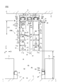
- FIG. 15 is a plan view showing an example of a stocker system SYS4 according to the fourth embodiment.
- a stocker system SYS4 shown in FIG. 15 includes a stocker 100C.
- the stocker 100 ⁇ / b> C includes a plurality of shelves 10 and a crane 40.
- the stocker system SYS4 shown in FIG. 15 has a configuration in which two orbiting crane orbiting ceiling tracks 20A and 20B are connected by two connection tracks S4, and the crane 40 has a crane orbiting ceiling track. 20A, 20B, traveling on the connection track S4.
- the crane orbiting ceiling tracks 20 ⁇ / b> A and 20 ⁇ / b> B are arranged inside the orbiting ceiling track 30 ⁇ / b> A in a plan view and each have a straight section 21 and a connection section 22.
- the two straight sections 21 are provided so as to extend in parallel in the Y direction, and are arranged side by side in the X direction.
- the connection section 22 connects the ends of the two straight sections 21 on the + Y side and the ⁇ Y side.
- the two connecting tracks S4 are provided so as to connect the straight section 21 of the crane orbiting ceiling track 20A and the straight section 21 of the crane orbiting ceiling track 20B.
- the crane 40 travels in one direction (for example, counterclockwise in plan view) along the straight section 21 and the connection section 22 in each of the crane orbit ceiling tracks 20A and 20B. Further, the crane 40 moves from the crane orbiting ceiling track 20A to the crane orbiting ceiling track 20B through the connection track S4 or from the crane orbiting ceiling track 20B to the crane orbiting ceiling track 20A through the connection track S4. be able to.
- the plurality of cranes 40 are in a first state in which the articles 2 are conveyed while orbiting in each of the crane orbiting ceiling tracks 20A and 20B, a part of each of the crane orbiting ceiling tracks 20A and 20B, and two connections
- the crane 2 can be operated in any of the second state in which the article 2 is conveyed while orbiting the orbit 20C constituted by the orbit S4, and the plurality of cranes 40 are operated in the first state and the second state.
- the controller which controls to operate in either of the states is provided.
- This controller can change the ratio (time ratio) at which the plurality of cranes 40 operate in the first state and the second state.
- the controller selectively establishes the first state and the second state (or the first state, the second state) so that the transfer efficiency is improved according to the operating state of the processing device TL in each bay. Change the rate of operation in the state of).
- the crane ceiling ceiling tracks 20A and 20B have the same or substantially the same shape or size in plan view, and are arranged side by side in the Y direction.
- the crane ceiling ceiling tracks 20A and 20B may have different shapes or sizes in plan view.
- the crane orbit ceiling tracks 20A and 20B and the connection track S4 are provided in a state of being suspended from the system ceiling SC1 or the ceiling C, similarly to the crane ceiling track 20 shown in FIG.
- the orbiting ceiling track 30B on which the ceiling transport vehicle 50 travels is disposed between the inter-bay routes R1, R1A and the inter-bay routes R2, R2A.
- the interbay routes R1 and R1A are provided to extend in the Y direction in parallel.
- the inter-bay routes R2 and R2A are provided to extend in the Y direction in parallel.
- Interbay routes R1, R1A, R2, and R2A are interbay tracks that connect intrabays.
- a main passage PSA Below the place where the interbay routes R1, R1A, R2, R2A, the orbiting ceiling track 30B, and the stocker 100C are provided is a main passage PSA.
- the main passage PSA is formed between the processing device TL in the intra bay and the processing device TL in the opposing intra bay.
- the main passage PSA is a worker passage and is used as, for example, a carry-in or carry-out passage for the processing apparatus TL.
- the orbiting ceiling track 30B is formed using two straight portions 31B, a connection portion 32B, and a part of the inter-bay routes R1A and R2A.
- the two linear portions 31B are provided so as to extend in parallel in the Y direction, and are arranged side by side in the X direction.
- the + Y side and ⁇ Y side ends of the + X side straight line portion 31B are connected to the interbay route R2A.
- the + Y side and ⁇ Y side ends of the ⁇ X side straight line portion 31B are connected to the interbay route R1A.
- the straight portion 31A is an additional rail provided to be closer to the stocker 100C (the plurality of shelves 10) than the inter-bay routes R1A and R2A arranged above the main passage PSA so that the stocker 100C can be easily accessed. With this configuration, the width of the stocker 100C in the X direction can be suppressed even when the width of the main passage PSA in the X direction is wide.
- the circulating ceiling track 30B may be formed using the inter-bay routes R1A and R2A instead of the straight portion 31B.
- the connecting portion 32B is provided so as to connect the interbay route R1A and the interbay route R2A on the + Y side and the ⁇ Y side of the two straight portions 31B.
- the orbiting ceiling track 30B is provided in a state of being suspended from the system ceiling SC2 or the ceiling C, similarly to the orbiting ceiling track 30 shown in FIG.
- the ceiling transport vehicle 50 can travel in one direction (for example, a clockwise direction in plan view) along the circulating ceiling track 30B. Further, the crane 40 also circulates in one direction (for example, a clockwise direction in a plan view) along each of the crane orbit ceiling tracks 20A and 20B. Thus, by making the crane 40 and the overhead conveyance vehicle 50 circulate in the same direction, both the crane 40 and the overhead conveyance vehicle 50 can be controlled by the controller having the same type of control program. The control can be simplified compared to the control that circulates around.
- the ceiling transport vehicle 50 travels via the interbay route R1A or the interbay route R2A when entering the connecting portion 32B from the straight portion 31B and entering the straight portion 31B from the connecting portion 32B.
- the orbiting ceiling track 30B is not limited to the configuration using a part of the inter-bay route R1A or the inter-bay route R2A, and the + Y side and ⁇ Y side ends of the straight portion 31B may be connected by the connection portion 32B. Good.
- the plurality of shelves 10 are provided between the orbiting ceiling track 30B and the crane orbiting ceiling tracks 20A and 20B and inside the crane orbiting ceiling tracks 20A and 20B in plan view. That is, all the plurality of shelves 10 are arranged inside the circular ceiling track 30B in plan view.
- the plurality of shelves 10 have a storage shelf 11 and a loading / unloading port 12.
- the entry / exit port 12 is provided on the plurality of shelves 10 arranged between the orbiting ceiling track 30B and the crane orbiting ceiling tracks 20A and 20B.
- the plurality of shelves 10 provided inside the crane ceiling ceiling track 20 ⁇ / b> A are inaccessible to the ceiling transport vehicle 50, and therefore do not have the entry / exit port 12, and have only the storage shelf 11.
- the entry / exit port 12 is described at the + Y side end of the plurality of shelves 10, but the lowermost stage of the plurality of shelves 10 is the entry / exit port 12 as in the first embodiment described above. It is.
- the stocker 100C is installed above the main passage PSA, and the height H1 (see FIG. 1) of the lower ends of the plurality of shelves 10 and the height H3 (see FIG. 1) of the lower ends of the cranes 40 (mast 43) are as follows. It is higher than the height H2 (see FIG. 1) of the processing device TL.
- the main passage PSA can be used for carrying in or carrying out the processing apparatus TL or the like.
- a branch line S3 is provided between the + Y side of the crane orbiting ceiling track 20A, the ⁇ Y side of the crane orbiting ceiling track 20B, and the connection portion 32B of the orbiting ceiling track 30B.
- the crane 40 can enter the orbiting ceiling track 30B via the branch line S3, and can enter the interbay route R1A or the interbay route R2A from the orbiting ceiling track 30B.
- the branch line S3 may not be provided.
- storage shelves STB are provided on the plurality of orbiting ceiling tracks 30 connected to the inter-bay route R1 or the inter-bay route R2.
- the storage shelf STB is provided, for example, suspended from the ceiling C, on which the article 2 can be placed.
- the overhead conveyance vehicle 50 can deliver the article 2 to and from the storage shelf STB.
- a stocker 100 as shown in FIG. 1 or the like may be disposed instead of the storage shelf STB being disposed on the orbiting ceiling track 30.
- the article 2 can be passed from the crane 40 to the ceiling transport vehicle 50 via the loading / unloading port 12, and from the ceiling transport vehicle 50 to the crane 40.
- Article 2 can be delivered.
- two cranes 40 are arranged on the crane ceiling ceiling tracks 20 ⁇ / b> A and 20 ⁇ / b> B, respectively, but the number of cranes 40 is arbitrary.
- the plurality of shelves 10 are provided between the orbiting ceiling track 30B and the crane orbiting ceiling tracks 20A and 20B, and inside the crane orbiting ceiling tracks 20A and 20B. Since it is provided, many articles 2 can be stored, and a large-capacity stocker system can be realized.
- the several shelf 10 of 2 rows is arrange
- the direction of the article 2 is changed. It can be made uniform (same), and control related to the transfer of the article 2 by the crane 40 becomes easy.
- a plurality of shelves 10 in one row are arranged inside the crane orbit ceiling tracks 20A and 20B, when the article 2 is delivered to the plurality of shelves 10 from the + X side, and the article 2 from the ⁇ X side.
- the plurality of shelves Control to rotate the article 2 is necessary so that the articles 2 stored in the same direction.
- the plurality of shelves 10, the crane ceiling track 20, the crane orbiting ceiling tracks 20A and 20B, and the orbiting ceiling tracks 30, 30A and 30B are the ceiling C or the system ceiling.
- the configuration suspended from SC1, SC2, and SC3 has been described as an example, but is not limited to this configuration.
- at least one of the plurality of shelves 10, the crane ceiling track 20, the crane orbiting ceiling tracks 20 ⁇ / b> A and 20 ⁇ / b> B, and the orbiting ceiling tracks 30, 30 ⁇ / b> A, and 30 ⁇ / b> B is supported by a column or frame that extends upward from the floor F.
Priority Applications (7)
| Application Number | Priority Date | Filing Date | Title |
|---|---|---|---|
| CN201980020969.6A CN111886190B (zh) | 2018-03-22 | 2019-02-04 | 储料器系统 |
| SG11202009270XA SG11202009270XA (en) | 2018-03-22 | 2019-02-04 | Stocker system |
| JP2020507409A JP6897864B2 (ja) | 2018-03-22 | 2019-02-04 | ストッカシステム |
| US16/981,727 US11239102B2 (en) | 2018-03-22 | 2019-02-04 | Stocker system |
| KR1020207026828A KR102431540B1 (ko) | 2018-03-22 | 2019-02-04 | 스토커 시스템 |
| EP19771493.4A EP3770082B1 (en) | 2018-03-22 | 2019-02-04 | Stocker system |
| IL277445A IL277445A (en) | 2018-03-22 | 2020-09-17 | Inventory storage system |
Applications Claiming Priority (2)
| Application Number | Priority Date | Filing Date | Title |
|---|---|---|---|
| JP2018-054470 | 2018-03-22 | ||
| JP2018054470 | 2018-03-22 |
Publications (1)
| Publication Number | Publication Date |
|---|---|
| WO2019181241A1 true WO2019181241A1 (ja) | 2019-09-26 |
Family
ID=67987101
Family Applications (1)
| Application Number | Title | Priority Date | Filing Date |
|---|---|---|---|
| PCT/JP2019/003837 WO2019181241A1 (ja) | 2018-03-22 | 2019-02-04 | ストッカシステム |
Country Status (9)
| Country | Link |
|---|---|
| US (1) | US11239102B2 (zh) |
| EP (1) | EP3770082B1 (zh) |
| JP (1) | JP6897864B2 (zh) |
| KR (1) | KR102431540B1 (zh) |
| CN (1) | CN111886190B (zh) |
| IL (1) | IL277445A (zh) |
| SG (1) | SG11202009270XA (zh) |
| TW (1) | TWI814792B (zh) |
| WO (1) | WO2019181241A1 (zh) |
Families Citing this family (6)
| Publication number | Priority date | Publication date | Assignee | Title |
|---|---|---|---|---|
| US7632299B2 (en) | 2004-01-22 | 2009-12-15 | Boston Scientific Scimed, Inc. | Medical devices |
| JP7095750B2 (ja) * | 2018-11-06 | 2022-07-05 | 村田機械株式会社 | 天井吊下棚 |
| KR102530860B1 (ko) * | 2018-12-26 | 2023-05-10 | 무라다기카이가부시끼가이샤 | 보관 시스템 |
| KR102235517B1 (ko) * | 2020-11-02 | 2021-04-01 | 시너스텍 주식회사 | 오버헤드 호이스트 방식의 스토커 시스템 |
| TWI747623B (zh) * | 2020-11-20 | 2021-11-21 | 迅得機械股份有限公司 | 晶圓盒倉儲的校正補償系統與方法 |
| KR20230094359A (ko) | 2021-12-21 | 2023-06-28 | 세메스 주식회사 | 물품 처리 장치 |
Citations (7)
| Publication number | Priority date | Publication date | Assignee | Title |
|---|---|---|---|---|
| US20080240892A1 (en) * | 2007-03-28 | 2008-10-02 | International Business Machines Corporation | Storage buffer device for automated material handling systems |
| JP2009154983A (ja) * | 2007-12-25 | 2009-07-16 | Asyst Technologies Japan Inc | 保管庫及び入出庫方法 |
| WO2013150841A1 (ja) * | 2012-04-05 | 2013-10-10 | 村田機械株式会社 | 搬送システム |
| JP5880693B2 (ja) | 2012-04-05 | 2016-03-09 | 村田機械株式会社 | 搬送システム |
| WO2017029871A1 (ja) * | 2015-08-14 | 2017-02-23 | 村田機械株式会社 | 搬送システム |
| WO2018003287A1 (ja) * | 2016-06-27 | 2018-01-04 | 村田機械株式会社 | 搬送システム |
| JP2018054470A (ja) | 2016-09-29 | 2018-04-05 | マツダ株式会社 | 車両用物標検出システム |
Family Cites Families (14)
| Publication number | Priority date | Publication date | Assignee | Title |
|---|---|---|---|---|
| TW348162B (en) * | 1996-09-30 | 1998-12-21 | Murada Kikai Kk | Work carrying system |
| JP3991852B2 (ja) * | 2002-12-09 | 2007-10-17 | 村田機械株式会社 | 天井搬送車システム |
| JP2005150129A (ja) | 2003-11-11 | 2005-06-09 | Asyst Shinko Inc | 移載装置及び移載システム |
| US7661919B2 (en) * | 2005-09-28 | 2010-02-16 | Muratec Automation Co., Ltd. | Discontinuous conveyor system |
| JP5228504B2 (ja) | 2008-01-24 | 2013-07-03 | 村田機械株式会社 | 保管庫及び入出庫方法 |
| SG178103A1 (en) * | 2009-11-27 | 2012-03-29 | Daifuku Kk | Ceiling conveyor car |
| TWI408092B (zh) * | 2010-06-18 | 2013-09-11 | Jgc Corp | Processing equipment |
| JP5229363B2 (ja) * | 2010-11-04 | 2013-07-03 | 村田機械株式会社 | 搬送システム及び搬送方法 |
| JP5713202B2 (ja) * | 2012-01-27 | 2015-05-07 | 株式会社ダイフク | 物品搬送設備 |
| EP2860136B1 (en) * | 2012-06-08 | 2020-08-05 | Murata Machinery, Ltd. | Conveyance system and temporary storage method of articles in conveyance system |
| US9385019B2 (en) * | 2012-06-21 | 2016-07-05 | Globalfoundries Inc. | Overhead substrate handling and storage system |
| US20140108027A1 (en) * | 2012-10-12 | 2014-04-17 | Mckesson Automation Inc. | Apparatuses, systems, and methods for delivering medications from a central pharmacy to a patient in a healthcare facility |
| JP6048686B2 (ja) * | 2014-09-25 | 2016-12-21 | 村田機械株式会社 | 一時保管装置と搬送システム及び一時保管方法 |
| JP6578794B2 (ja) * | 2015-08-04 | 2019-09-25 | 村田機械株式会社 | 搬送システム |
-
2019
- 2019-02-04 SG SG11202009270XA patent/SG11202009270XA/en unknown
- 2019-02-04 KR KR1020207026828A patent/KR102431540B1/ko active IP Right Grant
- 2019-02-04 US US16/981,727 patent/US11239102B2/en active Active
- 2019-02-04 JP JP2020507409A patent/JP6897864B2/ja active Active
- 2019-02-04 CN CN201980020969.6A patent/CN111886190B/zh active Active
- 2019-02-04 WO PCT/JP2019/003837 patent/WO2019181241A1/ja active Application Filing
- 2019-02-04 EP EP19771493.4A patent/EP3770082B1/en active Active
- 2019-03-15 TW TW108108930A patent/TWI814792B/zh active
-
2020
- 2020-09-17 IL IL277445A patent/IL277445A/en unknown
Patent Citations (7)
| Publication number | Priority date | Publication date | Assignee | Title |
|---|---|---|---|---|
| US20080240892A1 (en) * | 2007-03-28 | 2008-10-02 | International Business Machines Corporation | Storage buffer device for automated material handling systems |
| JP2009154983A (ja) * | 2007-12-25 | 2009-07-16 | Asyst Technologies Japan Inc | 保管庫及び入出庫方法 |
| WO2013150841A1 (ja) * | 2012-04-05 | 2013-10-10 | 村田機械株式会社 | 搬送システム |
| JP5880693B2 (ja) | 2012-04-05 | 2016-03-09 | 村田機械株式会社 | 搬送システム |
| WO2017029871A1 (ja) * | 2015-08-14 | 2017-02-23 | 村田機械株式会社 | 搬送システム |
| WO2018003287A1 (ja) * | 2016-06-27 | 2018-01-04 | 村田機械株式会社 | 搬送システム |
| JP2018054470A (ja) | 2016-09-29 | 2018-04-05 | マツダ株式会社 | 車両用物標検出システム |
Also Published As
| Publication number | Publication date |
|---|---|
| SG11202009270XA (en) | 2020-10-29 |
| US11239102B2 (en) | 2022-02-01 |
| EP3770082B1 (en) | 2023-09-06 |
| EP3770082A4 (en) | 2021-12-15 |
| TWI814792B (zh) | 2023-09-11 |
| KR20200121355A (ko) | 2020-10-23 |
| CN111886190A (zh) | 2020-11-03 |
| US20210043487A1 (en) | 2021-02-11 |
| JP6897864B2 (ja) | 2021-07-07 |
| TW201940396A (zh) | 2019-10-16 |
| JPWO2019181241A1 (ja) | 2021-05-13 |
| EP3770082A1 (en) | 2021-01-27 |
| CN111886190B (zh) | 2022-06-28 |
| KR102431540B1 (ko) | 2022-08-11 |
| IL277445A (en) | 2020-11-30 |
Similar Documents
| Publication | Publication Date | Title |
|---|---|---|
| WO2019181241A1 (ja) | ストッカシステム | |
| CN113348141B (zh) | 搬送系统 | |
| JP6849065B2 (ja) | 搬送システム及び搬送方法 | |
| WO2020153040A1 (ja) | 保管システム | |
| JP7136236B2 (ja) | 保管システム | |
| CN113195379B (zh) | 保管系统 | |
| JP6809612B2 (ja) | 自動倉庫システム、及び自動倉庫システムの制御方法 |
Legal Events
| Date | Code | Title | Description |
|---|---|---|---|
| 121 | Ep: the epo has been informed by wipo that ep was designated in this application |
Ref document number: 19771493 Country of ref document: EP Kind code of ref document: A1 |
|
| ENP | Entry into the national phase |
Ref document number: 20207026828 Country of ref document: KR Kind code of ref document: A |
|
| ENP | Entry into the national phase |
Ref document number: 2020507409 Country of ref document: JP Kind code of ref document: A |
|
| NENP | Non-entry into the national phase |
Ref country code: DE |
|
| WWE | Wipo information: entry into national phase |
Ref document number: 2019771493 Country of ref document: EP |
|
| ENP | Entry into the national phase |
Ref document number: 2019771493 Country of ref document: EP Effective date: 20201022 |