WO2019159737A1 - レーザ溶接方法及びレーザ溶接システム - Google Patents
レーザ溶接方法及びレーザ溶接システム Download PDFInfo
- Publication number
- WO2019159737A1 WO2019159737A1 PCT/JP2019/003832 JP2019003832W WO2019159737A1 WO 2019159737 A1 WO2019159737 A1 WO 2019159737A1 JP 2019003832 W JP2019003832 W JP 2019003832W WO 2019159737 A1 WO2019159737 A1 WO 2019159737A1
- Authority
- WO
- WIPO (PCT)
- Prior art keywords
- laser
- laser beam
- tip
- pattern
- irradiation
- Prior art date
- Legal status (The legal status is an assumption and is not a legal conclusion. Google has not performed a legal analysis and makes no representation as to the accuracy of the status listed.)
- Ceased
Links
Images








Classifications
-
- B—PERFORMING OPERATIONS; TRANSPORTING
- B23—MACHINE TOOLS; METAL-WORKING NOT OTHERWISE PROVIDED FOR
- B23K—SOLDERING OR UNSOLDERING; WELDING; CLADDING OR PLATING BY SOLDERING OR WELDING; CUTTING BY APPLYING HEAT LOCALLY, e.g. FLAME CUTTING; WORKING BY LASER BEAM
- B23K26/00—Working by laser beam, e.g. welding, cutting or boring
- B23K26/20—Bonding
- B23K26/21—Bonding by welding
-
- H—ELECTRICITY
- H02—GENERATION; CONVERSION OR DISTRIBUTION OF ELECTRIC POWER
- H02K—DYNAMO-ELECTRIC MACHINES
- H02K15/00—Processes or apparatus specially adapted for manufacturing, assembling, maintaining or repairing of dynamo-electric machines
- H02K15/08—Forming windings by laying conductors into or around core parts
- H02K15/085—Forming windings by laying conductors into or around core parts by laying conductors into slotted stators
-
- H—ELECTRICITY
- H02—GENERATION; CONVERSION OR DISTRIBUTION OF ELECTRIC POWER
- H02K—DYNAMO-ELECTRIC MACHINES
- H02K3/00—Details of windings
- H02K3/04—Windings characterised by the conductor shape, form or construction, e.g. with bar conductors
Definitions
- the present invention relates to a laser welding method and a laser welding system for electrically joining ends of coil segments constituting a coil used in a rotating electric machine such as a motor or a generator or an electromagnetic device such as a transformer.
- a plurality of coil segments formed by bending a rectangular wire having a rectangular cross section into a U shape are inserted into a core slot, and the distal end portion in the insertion direction of the coil segment protruding from the end surface of the core is surrounded. Bending is performed in the opposite direction for each layer in the direction, and tip portions facing each other in adjacent layers are electrically connected to form a coil in which a plurality of coil segments are connected in series.
- the insulating film is removed in advance in the insertion direction of the coil segment, and the distal parts from which the insulating film has been removed are in a state of being abutted side by side so that the rectangular tip surfaces form one plane.
- arc welding such as TIG (Tungsten Inert Gas) welding or laser welding such as YAG (Yttrium Aluminum Garnet) laser.
- the laser light is generally irradiated from the direction perpendicular to the front end surface around the boundary from the viewpoint of equalizing the energy supply to the two front end surfaces and eliminating the melting bias. For this reason, when a slight gap exists, the laser beam may enter the inside through the gap and the insulating coating may be destroyed. Since the coil segments of the other layers and the coil segments of the other phases are present below the welded part, if the laser beam enters deeply, these insulation films are destroyed, and interlayer insulation or interphase insulation is not achieved. There was a risk of being cut off.
- Patent Document 1 proposes a method of joining by irradiating the laser beam obliquely.
- the conductor joining method proposed in Patent Document 1 is configured such that one of the two opposing surfaces of the bare conductor is irradiated with a laser beam obliquely. Is melted locally, and the other opposing surface is melted by the heat, so that the whole is melted. According to this oblique irradiation method, there is no concern that the laser beam enters the inside through the boundary gap and destroys the insulating coating.
- the tip surface of the end part to be welded of this type of coil segment has a rectangular (for example, rectangular) shape, and the shape after welding is finished in a smooth hemispherical or dome-like shape that is symmetric. desirable. If there are non-smooth parts or corners, cracks will occur due to vibrations over time, etc., and the weld will separate, or a part of the weld deposit will fall off and enter the core, causing a short circuit. It is because it is easy to do.
- the present invention has been made in view of such a situation, and an object of the present invention is to obtain a high-quality welding quality by laser welding while solving the problems caused by laser light entering.
- the laser welding method of the present invention is configured so that the tip portions of the coil segments projecting from the end face of the core are opposed to each other in the radial direction of the core.
- the laser beam is irradiated with an irradiation pattern that is symmetric with respect to the boundary between the tip surfaces.
- a laser beam is irradiated perpendicularly to each of the tip surfaces, and the laser beam is moved while crossing the boundary between the tip surfaces. May be turned off.
- the irradiation pattern includes a first pattern that continuously or intermittently makes a round around the outer periphery of a single plane that combines the respective front end surfaces, and a continuous or intermittent inside of the first pattern.
- the second pattern may be included.
- the irradiation pattern may include a continuous or intermittent pattern along a diagonal line of one plane that combines the tip surfaces.
- the distal end portions of the coil segments protruding from the end surface of the core are opposed to each other in the radial direction of the core.
- a control device that controls the laser light irradiation device so that the laser light irradiates each tip surface with an irradiation pattern that is symmetrical with respect to a boundary between the tip surfaces.
- control device is configured such that the laser light is irradiated perpendicularly to each of the front end surfaces and moves while crossing the boundary between the front end surfaces, and the laser light is moved to the boundary.
- the laser beam irradiation device may be controlled to turn off the laser beam irradiation when crossing the line.
- control device includes an input device for inputting welding conditions, a welding condition including an area of the tip surface, and a reference table in which a relationship between the output and / or moving speed of the laser beam is obtained in advance.
- the laser beam irradiation device may be controlled by selecting the output and / or moving speed of the corresponding laser beam from the reference table based on the welding condition input by the input device.
- FIG. 8A It is a figure which shows the state which the clearance gap has produced after pressing and clamping with the holding member from the state of FIG. 8A. It is a front view which shows the ideal welding shape of the front-end
- FIG. 4 is a block diagram showing an outline of a laser welding system according to an embodiment of the present invention.
- the distal end portions 6c of the distal end portion 6c of the coil segment protruding from the end surface 4b of the core 4 are opposed to each other in the core 4 on the rectangular distal end surface of the distal end portion 6c.
- This is a laser welding system that welds by irradiating each tip surface with laser light in a state in which the heights in the axial direction of the cores are substantially the same and are butted in the radial direction of the core 4.
- the laser welding system 2 controls the laser light irradiation device 8 so as to irradiate each tip surface with the laser light irradiation device 8 that irradiates the laser light Lb and an irradiation pattern in which the movement trajectory of the laser light is substantially the same.
- a control device 10, a touch panel type input device 12 for inputting welding conditions, a gripper mechanism described later for pressurizing and clamping a pair of tip portions 6c to be welded, and the most advanced of the pair of tip portions 6c to be welded Has a cutting mechanism 23 and the like.
- the control device 10 and the input device 12 are separately displayed here, the input device 12 may be integrated with the control device 10.
- the laser light irradiation device 8 includes a laser oscillator 16, a laser head 18 that emits laser light vertically toward a welding target, an optical fiber 20 that transmits the laser light oscillated from the laser oscillator 16 to the laser head 18, and A drive mechanism 22 for displacing the laser head 18 two-dimensionally is provided.
- the laser head 18 incorporates a condensing optical system (a collimating lens or a condensing lens) for condensing the laser light transmitted through the optical fiber 20 to an appropriate spot diameter.
- the control device 10 is a microcomputer having a CPU (Central Processing Unit), a RAM (Random Access Memory), a ROM (Read Only Memory), an I / O interface, etc., and controls the output of the laser oscillator 16 or a drive mechanism. The movement of the laser head 18 is controlled via 22.
- CPU Central Processing Unit
- RAM Random Access Memory
- ROM Read Only Memory
- I / O interface etc.
- the core 4 is supported by the index mechanism 24, and is rotated by a predetermined angle (index rotation) in the circumferential direction of the core 4 in order to change the welding position.
- Index rotation by the index mechanism 24 is controlled by the control device 10.
- the position of the welding position may be changed by moving the laser head 18.
- the coil segment is formed by bending a rectangular wire whose surface is covered with an insulating coating made of enamel or polyimide resin into a U shape. More specifically, the coil segment 6 includes a pair of slot insertion portions 6a and 6a extending linearly and a connecting portion 6b that connects them, and the connecting portion 6b has a step shape (crank shape). ing.
- the tip of the tip portion 6c of the slot insertion portion 6a has an insulating coating removed for electrical joining by welding.
- this portion is referred to as a peeling portion 6d.
- the coil segment 6 is inserted from the end surface 4 a side of the core 4 shown in FIG. 4, and the tip end portion 6 c of the slot insertion portion 6 a protrudes from the end surface 4 b of the core 4.
- the connecting portion 6b protrudes from the end face 4a of the core 4, but is omitted in FIG.
- the tip end portion 6c of the coil segment 6 protruding from the end face 4b of the core 4 is bent in different directions in the circumferential direction by twist processing for each layer adjacent to the core 4 in the radial direction.
- FIG. 6 After twist processing, as shown in FIG. 6, the front end portions 6c of adjacent layers face each other.
- reference numeral 4c denotes a plurality of slots arranged radially in the circumferential direction of the core 4
- 5 denotes an insulating sheet made of paper or synthetic resin inserted into the slot 4c.
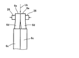
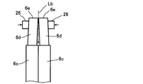
- the peeling portions 6 d are aligned with each other by a positioning tool (not shown) in the circumferential direction of the core 4, and are pressed and clamped from the radial direction of the core 4 by a pair of gripping members 26. And matched.
- the gripper mechanism 14 is composed of a pair of gripping members 26 and a drive source (not shown) that drives them.
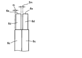
- FIG. 7 shows a state after cutting. In this state, that is, in a state where the heights of the front end surfaces 6e in the axial direction of the core 4 are substantially the same, the peeling portions 6d are butted against each other in the radial direction of the core 4. Laser welding by the welding system 2 is performed.
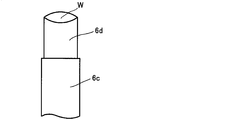
- 9A and 9B show an ideal shape after welding. It is desirable that the metal (here, copper) melted by the irradiation of the laser beam Lb is solidified into a smooth arc shape (including a hemispherical or dome-shaped concept) by surface tension. With such a welded shape W, the gripping member 26 after welding is smoothly pulled out, and cracks due to stress concentration are less likely to occur, so that the welded part is missing and the welded part is separated. And other problems can be suppressed.
- the metal here, copper
- laser light is not irradiated at the boundary between the pair of tip surfaces 6e shown in FIG. 7 where a gap is formed.
- laser welding can be performed without causing the laser light Lb to enter from the gap.
- the laser beam is irradiated with an irradiation pattern that is symmetric with respect to the boundary between the tip surfaces 6e. As a result, a smooth arc-shaped weld shape as shown in FIGS. 9A and 9B can be stably obtained.
- FIG. 1 is a plan view showing a state in which a pair of peeling portions 6d of the coil segment 6 shown in FIG. 6 are abutted side by side in the radial direction of the core 4, and reference numeral 28 denotes a pair of tip surfaces shown in FIG. The boundary between 6e is shown.
- the right rectangular front end surface in the figure is distinguished as 6eR
- the left rectangular front end surface is identified as 6eL.
- Reference numeral 6eC indicates one plane obtained by combining the tip surface 6eR and the tip surface 6eL.
- a rectangular preheating pattern 30 indicated by a one-dot chain line that goes around the outer periphery of the plane 6eC is a movement trajectory of the laser beam Lb, and continuously or in the vicinity of the outer periphery of one plane 6eC obtained by combining the tip surfaces 6eR and 6eL.
- An example of a first pattern that makes an intermittent circuit is shown.
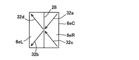
- the X-shaped line corner elimination pattern 32 indicated by the alternate long and short dash line along the diagonal line of the plane 6eC shows an example of a continuous or intermittent pattern along the diagonal line of the plane 6eC, due to the movement locus of the laser light Lb. .
- the main welding pattern 34 of the rectangular line shown with the dashed-dotted line located inside the preheating pattern 30 is the 2nd pattern which circles the inside of the preheating pattern 30 continuously or intermittently by the movement locus of the laser beam Lb.
- the “movement trajectory” is a linear trajectory after the spot of the laser beam has moved, and the moving direction, moving order, moving speed, etc. of the laser beam do not matter.
- the laser beam Lb is irradiated and welded to the plane 6eC with the irradiation pattern including the above three patterns.
- the preheating pattern 30 is an irradiation pattern that continuously or intermittently makes a round around the outer periphery of the flat surface 6eC. “Continuous” means that the laser beam Lb is turned on to move, and “intermittent” means that the laser beam Lb is turned on and off repeatedly.
- the laser beam Lb moves straight to the left starting from the upper right corner of the plane 6eC (moving locus 30a), and moves straight across the boundary 28 to the upper left corner of the tip surface 6eL (moving locus 30b).
- the laser beam Lb is not irradiated when crossing the boundary 28. That is, the control device 10 turns off the irradiation of the laser beam Lb before the boundary 28 based on the movement distance on the tip surface 6eR calculated in advance, and the irradiation port of the laser head 18 enters the tip surface 6eL beyond the boundary 28. Immediately thereafter, control is performed to turn on the irradiation of the laser beam Lb.
- FIG. 1 the outline of the movement trajectory of each irradiation pattern is roughly shown for easy understanding, and irradiation OFF when crossing the boundary 28 is not reflected.
- the irradiation off period ⁇ t of the laser beam Lb is set corresponding to the maximum value of the gap formed randomly at the boundary 28 of each tip surface pair, and is obtained by experiment.
- the irradiation off period ⁇ t also varies depending on the moving speed of the laser light Lb.
- the laser beam Lb After the laser beam Lb travels straight to the upper left corner of the tip surface 6eL, it changes its direction by 90 ° and moves straight to the lower left corner of the tip surface 6eL (movement locus 30c). Thereafter, the direction is further changed by 90 ° to move straight (moving locus 30d), and move straight across the boundary 28 to the lower right corner of the tip surface 6eR (moving locus 30e). When crossing the boundary 28, the laser beam Lb is not irradiated as described above.
- control device 10 turns off the irradiation of the laser light Lb before the boundary 28 based on the movement distance on the tip surface 6eL calculated in advance, and the irradiation port of the laser head 18 enters the tip surface 6eR beyond the boundary 28. Immediately thereafter, control is performed to turn on the irradiation of the laser beam Lb. After the laser beam Lb moves straight to the lower right corner of the front end face 6eR, it changes its direction by 90 ° and moves straight to the start point (movement locus 30f).
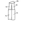
- the preheating pattern 30 is provided in order to define the outer shape of the weld shape so that the bulging portion Wa and the sag are not generated outside the flat surface 6eC (see FIG. 1) of the molten metal as shown in FIG. 9C. .
- it functions as a frame for restricting the random flow of the molten metal by the main welding described later.
- the movement trajectories 30a to 30f are formed by continuous irradiation of the laser light Lb in the respective ranges, but may be formed by intermittent irradiation.
- the starting point in the preheating pattern 30 is not limited to the above, and may be any part of the rectangular moving locus in FIG. 2A, and the moving direction is not limited.
- the corner eraser pattern 32 is an irradiation pattern that moves continuously along the diagonal line of the plane 6eC shown in FIG. 1, and the corner eraser pattern 32 has an outer corner portion Wb as shown in FIG. 9D. It is provided in order to prevent solidification in a state of protruding. Further, the corner eraser pattern 32 is also a pattern that contributes to the preheating of the flat surface 6 eC like the preheating pattern 30.
- the laser beam Lb moves straight diagonally downward to the left starting from the upper right corner of the plane 6eC (moving locus 32a), and moves linearly across the boundary 28 to the lower left corner of the tip surface 6eL. (Movement locus 32b).
- the laser beam Lb is not irradiated when crossing the boundary 28. That is, the control device 10 turns off the irradiation of the laser beam Lb before the boundary 28 based on the movement distance on the tip surface 6eR calculated in advance, and the irradiation port of the laser head 18 enters the tip surface 6eL beyond the boundary 28. Immediately thereafter, control is performed to turn on the irradiation of the laser beam Lb.
- the laser head 18 When the irradiation of the laser beam along one of the diagonal lines of the plane 6eC is completed, the laser head 18 is displaced in a state where the irradiation of the laser beam Lb is turned off. For example, the laser beam Lb obliquely upwards to the left starting from the lower right corner of the plane 6eC. Moves straight (moving locus 32c), and moves diagonally across the boundary 28 to the upper left corner of the tip surface 6eL (moving locus 32d).
- the laser beam Lb is not irradiated when crossing the boundary 28. That is, the control device 10 turns off the irradiation of the laser beam Lb before the boundary 28 based on the movement distance on the tip surface 6eR calculated in advance, and the irradiation port of the laser head 18 enters the tip surface 6eL beyond the boundary 28. Immediately thereafter, control is performed to turn on the irradiation of the laser beam Lb.
- the method for determining the irradiation off period of the laser beam Lb is the same as that in the case of the preheating pattern 30.
- the two starting points in the corner eraser pattern 32 are not limited to the above, and may exist on the tip surface 6eL side, or may exist on both the tip surface 6eR and the tip surface 6eL. Further, the moving direction is not limited. For example, as shown in FIG. 3, it is good also as an irradiation pattern which consists of the movement locus
- the laser beam Lb may move too much due to the inertia of the movement of the laser head 18, and the corner portion may be crushed and adversely affect the welded shape.
- the irradiation pattern By setting the irradiation pattern to be the central portion of the plane 6eC, the above concerns can be solved. In this case, since the laser beam Lb does not cross the boundary 28 in any movement, the problem that the laser beam Lb enters inward from the gap at the boundary 28 does not occur.
- the main welding pattern 34 is an irradiation pattern that continuously goes around the inside of the preheating pattern 30 in the plane 6eC shown in FIG.
- the laser beam Lb moves straight to the left starting from the upper right of the plane 6eC (movement locus 34a), and moves straight to the upper left of the plane 6eC across the boundary 28 (movement locus 34b).
- the laser beam Lb is not irradiated when crossing the boundary 28.
- control device 10 turns off the irradiation of the laser beam Lb before the boundary 28 based on the movement distance on the tip surface 6eR calculated in advance, and the irradiation port of the laser head 18 enters the tip surface 6eL beyond the boundary 28. Immediately thereafter, control is performed to turn on the irradiation of the laser beam Lb.
- the laser beam Lb After the laser beam Lb travels straight to the upper left of the plane 6eC, it changes its direction by 90 ° and moves straight to the lower left of the plane 6eC (movement locus 34c). After that, the direction is further changed by 90 ° to move straight (moving track 34d), and move straight across the boundary 28 to the lower right of the plane 6eC (moving track 34e).
- the control device 10 turns off the irradiation of the laser light Lb before the boundary 28 based on the movement distance on the tip surface 6eL calculated in advance, and the irradiation port of the laser head 18 enters the tip surface 6eR beyond the boundary 28. Immediately thereafter, control is performed to turn on the irradiation of the laser beam Lb.
- the method for determining the irradiation off period of the laser beam Lb is the same as that in the case of the preheating pattern 30.
- the laser beam Lb moves straight to the lower right of the plane 6eC, it changes its direction by 90 ° and moves straight to the start point (movement track 34f).
- the starting point in the main welding pattern 34 is not limited to the above, and may be any part of the rectangular movement locus in FIG. 2C, and the movement direction is not limited.
- the irradiation with the preheating pattern 30 is performed before the irradiation with the laser beam Lb by the main welding pattern 34, solidification proceeds in a state where the random flow of the molten metal by the main welding pattern 34 is regulated.
- the bulging portion Wa as shown in FIG. 1 does not occur, and the welding shape has a smooth arcuate contour due to surface tension.
- the corner portion Wb as shown in FIG. As described above, the corner blanking pattern 32 contributes to the preheating of the plane 6 eC together with the preheating pattern 30.
- the irradiation of the laser beam Lb based on the corner eraser pattern 32 is unnecessary depending on the conditions. For example, when four corners of a flat wire are chamfered to some extent in order to prevent damage to the insulating film, the degree of the corner shape remains small. It may be omitted. Further, in such a case, the preheating of the plane 6eC may be emphasized, and the laser beam Lb may be moved in an X shape within the range of the preheating pattern 30 shown in FIG. That is, an X-shaped irradiation pattern for moving the laser beam Lb along the diagonal line of the rectangular outline may be added to the preheating pattern 30.
- the control device 10 executes laser welding using the preheating pattern 30, the corner erase pattern 32, and the main welding pattern 34 based on a predetermined program.
- the predetermined program irradiates the laser beam Lb along the preheating pattern 30, irradiates the laser beam Lb along the square erase pattern 32, and irradiates the laser beam Lb along the main welding pattern 34.
- the steps are programmed to be executed in this order.
- the order of irradiating the laser beam Lb along the preheating pattern 30 and the step of irradiating the laser beam Lb along the corner elimination pattern 32 may be reversed.
- the nonvolatile memory (for example, ROM) of the control device 10 has welding conditions in which the area of the plane 6eC, which is the sum of the areas of the tip surfaces 6eR and 6eL, is divided in stages, and the laser in the laser oscillator 16 of the laser light irradiation device 8.
- a reference table (control table) 11 in which the relationship between the output and / or the moving speed of the laser head 18 is obtained in advance is stored.
- the ROM stores a laser beam off period ( ⁇ t) when crossing the boundary 28.
- ⁇ t laser beam off period
- the control device 10 selects the output and / or moving speed of the corresponding laser beam from the reference table 11 based on the input welding condition, and the condition of the laser beam irradiation device 8 is selected. Set up.
- the welding conditions to be input in addition to the area (cross-sectional area) of the flat surface 6eC, the vertical and horizontal dimensions of the tip surfaces 6eR and 6eL, the material of the coil segment 6, the temperature and humidity in the welding environment, and the level difference of the flat surface 6eC (boundary 28 ),
- the flatness of the flat surface 6eC, the surface properties of the flat surface 6eC (presence of oil or the like), the temperature of the coil segment 6, and the like are set in advance as sensory parameters in stages, and the operator judges and inputs them visually or by hand. Also good.
- the control device 10 receives input of welding conditions (S11), and uses the vertical and horizontal dimensions of the front end surfaces 6eR and 6eL in the input welding conditions, and in-plane these
- the moving direction and the moving distance of the laser beam Lb in FIG. 5 are calculated based on each irradiation pattern stored in advance in the control device 10 (S12), and the reference table is based on the area of the plane 6eC obtained from the vertical and horizontal dimensions.
- the output and moving speed of the laser beam Lb are determined (S13).
- each irradiation pattern includes information on the position.
- the control device 10 determines the timing for temporarily turning off the laser beam Lb based on the information on the crossing position and the above-described laser beam off period ⁇ t (S14). When the temperature difference or the humidity difference exceeds the reference range, the determined value is corrected using an appropriate correction coefficient. Based on the above determination, the control device 10 controls the laser beam irradiation device 8 (S15), irradiates the tip surfaces 6eR and 6eL of the coil segment 6 with the laser beam Lb, and welds the coil segment 6.
- the reference table 11 may be transmitted from a terminal device connected to the control device 10 by wire or wireless LAN, or may be acquired from an external storage device such as a USB memory.
- the single laser beam Lb is moved and irradiated so as to cross the boundary 28.
- the tip surfaces 6eR and 6eL are applied to the tip surfaces by one laser beam Lb without crossing the boundary 28. It is good also as a structure irradiated individually with the irradiation pattern which becomes substantially symmetrical with respect to the boundary between them. That is, half of each irradiation pattern shown in FIG. 1 (the preheating pattern 30, the corner erase pattern 32, and the main welding pattern 34) may be individually performed on the respective tip surfaces 6eR and 6eL.
- the laser beam irradiation pattern may be only the main welding pattern, and the shape thereof is not limited to a rectangular shape, but is symmetrical with respect to the boundary between the tip surfaces facing each other in the radial direction of the core among the tip portions of the coil segments. Any irradiation pattern may be used.
- the number of laser beams Lb irradiated on the plane 6eC is not limited to one.
- the laser beam Lb oscillated by the laser beam irradiation device 8 is branched by a beam splitter such as a half mirror, and the tip surfaces 6eR and 6eL are individually irradiated with substantially the same irradiation pattern with two laser beams Lb. It is good.
- DESCRIPTION OF SYMBOLS 2 ... Laser welding system, 4 ... Core, 4b ... End surface, 6 ... Coil segment, 6c ... Tip part, 6e ... Tip surface, 6eC ... Plane, 8 ... Laser beam irradiation apparatus, 10 ... Control apparatus, 11 ... Reference table, DESCRIPTION OF SYMBOLS 12 ... Input device, 30 ... Preheating pattern, 30a, 30b, 30c, 30d, 30e, 30f ... Movement locus, 32 ... Square eraser pattern, 32a, 32b, 32c, 32d ... Movement locus, 34 ... Main welding pattern, 34a , 34b, 34c, 34d, 34e, 34f ... movement locus, Lb ... laser light
Landscapes
- Engineering & Computer Science (AREA)
- Power Engineering (AREA)
- Physics & Mathematics (AREA)
- Optics & Photonics (AREA)
- Manufacturing & Machinery (AREA)
- Plasma & Fusion (AREA)
- Mechanical Engineering (AREA)
- Laser Beam Processing (AREA)
- Connections Effected By Soldering, Adhesion, Or Permanent Deformation (AREA)
- Manufacture Of Motors, Generators (AREA)
Priority Applications (1)
| Application Number | Priority Date | Filing Date | Title |
|---|---|---|---|
| JP2020500400A JP7054265B2 (ja) | 2018-02-19 | 2019-02-04 | レーザ溶接方法及びレーザ溶接システム |
Applications Claiming Priority (2)
| Application Number | Priority Date | Filing Date | Title |
|---|---|---|---|
| JP2018027421 | 2018-02-19 | ||
| JP2018-027421 | 2018-02-19 |
Publications (1)
| Publication Number | Publication Date |
|---|---|
| WO2019159737A1 true WO2019159737A1 (ja) | 2019-08-22 |
Family
ID=67619859
Family Applications (1)
| Application Number | Title | Priority Date | Filing Date |
|---|---|---|---|
| PCT/JP2019/003832 Ceased WO2019159737A1 (ja) | 2018-02-19 | 2019-02-04 | レーザ溶接方法及びレーザ溶接システム |
Country Status (2)
| Country | Link |
|---|---|
| JP (1) | JP7054265B2 (https=) |
| WO (1) | WO2019159737A1 (https=) |
Cited By (22)
| Publication number | Priority date | Publication date | Assignee | Title |
|---|---|---|---|---|
| JPWO2021100457A1 (https=) * | 2019-11-20 | 2021-05-27 | ||
| JP2021093832A (ja) * | 2019-12-10 | 2021-06-17 | 日立Astemo株式会社 | コイル及びコイルの製造方法 |
| WO2021182634A1 (ja) * | 2020-03-12 | 2021-09-16 | アイシン・エィ・ダブリュ株式会社 | 回転電機用ステータ製造方法 |
| JPWO2021182636A1 (https=) * | 2020-03-12 | 2021-09-16 | ||
| JP2021145473A (ja) * | 2020-03-12 | 2021-09-24 | 株式会社アイシン | 回転電機用ステータ製造方法 |
| WO2022211133A1 (ja) * | 2021-04-02 | 2022-10-06 | 古河電気工業株式会社 | レーザ溶接方法およびレーザ溶接装置 |
| CN115383303A (zh) * | 2022-09-01 | 2022-11-25 | 深圳泰德激光技术股份有限公司 | 铜线焊接方法、设备及计算机可读存储介质 |
| JP2022177664A (ja) * | 2021-05-18 | 2022-12-01 | トヨタ自動車株式会社 | レーザ溶接方法 |
| JP2022182279A (ja) * | 2021-05-28 | 2022-12-08 | 古河電気工業株式会社 | レーザ溶接方法、レーザ溶接装置、および電気装置 |
| JPWO2023281930A1 (https=) * | 2021-07-08 | 2023-01-12 | ||
| US20230026208A1 (en) * | 2021-07-26 | 2023-01-26 | Denso Corporation | Stator and method of manufacturing same |
| US20230040799A1 (en) * | 2021-08-03 | 2023-02-09 | Denso Corporation | Stator and method for producing stator |
| EP4160875A1 (de) | 2021-10-01 | 2023-04-05 | Valeo eAutomotive Germany GmbH | Formleiter für eine wicklung eines aktivteils einer rotierenden elektrischen maschine, aktivteil für eine rotierende elektrische maschine und zugehöriges herstellungsverfahren |
| EP4160874A1 (de) | 2021-10-01 | 2023-04-05 | Valeo eAutomotive Germany GmbH | Verfahren zur herstellung eines aktivteils für eine rotierende elektrische maschine, aktivteil für eine rotierende elektrische maschine und rotierende elektrische maschine |
| EP4159358A1 (de) | 2021-10-01 | 2023-04-05 | Valeo eAutomotive Germany GmbH | Verfahren zur herstellung eines aktivteils für eine rotierende elektrische maschine, aktivteil für eine rotierende elektrische maschine und rotierende elektrische maschine |
| JP2023537399A (ja) * | 2020-08-14 | 2023-08-31 | コアレイズ オーワイ | 時間依存走査パターンおよびエネルギー入力を用いた金属ピン対のレーザ溶接 |
| JPWO2023175724A1 (https=) * | 2022-03-15 | 2023-09-21 | ||
| CN116833563A (zh) * | 2023-07-21 | 2023-10-03 | 联合汽车电子有限公司 | 一种扁线电机定子焊接工艺 |
| WO2024029530A1 (ja) | 2022-08-03 | 2024-02-08 | 古河電気工業株式会社 | コイルの溶接装置及び溶接方法 |
| JP2024019291A (ja) * | 2020-10-20 | 2024-02-08 | 古河電気工業株式会社 | レーザ溶接方法 |
| JP2025124143A (ja) * | 2024-02-14 | 2025-08-26 | 本田技研工業株式会社 | 導体接合方法 |
| WO2025210992A1 (ja) * | 2024-04-01 | 2025-10-09 | 三菱電機株式会社 | 回転電機および回転電機の製造方法 |
Families Citing this family (1)
| Publication number | Priority date | Publication date | Assignee | Title |
|---|---|---|---|---|
| GB2639192A (en) * | 2024-03-07 | 2025-09-17 | Jaguar Land Rover Ltd | Laser welding method |
Citations (3)
| Publication number | Priority date | Publication date | Assignee | Title |
|---|---|---|---|---|
| JPH06210476A (ja) * | 1993-01-14 | 1994-08-02 | Shibuya Kogyo Co Ltd | レーザ加工装置 |
| JP2014205166A (ja) * | 2013-04-12 | 2014-10-30 | 日本車輌製造株式会社 | レーザ溶接方法およびレーザ・アークハイブリッド溶接方法 |
| JP2018020340A (ja) * | 2016-08-02 | 2018-02-08 | トヨタ自動車株式会社 | 平角線のレーザ溶接方法 |
-
2019
- 2019-02-04 JP JP2020500400A patent/JP7054265B2/ja active Active
- 2019-02-04 WO PCT/JP2019/003832 patent/WO2019159737A1/ja not_active Ceased
Patent Citations (3)
| Publication number | Priority date | Publication date | Assignee | Title |
|---|---|---|---|---|
| JPH06210476A (ja) * | 1993-01-14 | 1994-08-02 | Shibuya Kogyo Co Ltd | レーザ加工装置 |
| JP2014205166A (ja) * | 2013-04-12 | 2014-10-30 | 日本車輌製造株式会社 | レーザ溶接方法およびレーザ・アークハイブリッド溶接方法 |
| JP2018020340A (ja) * | 2016-08-02 | 2018-02-08 | トヨタ自動車株式会社 | 平角線のレーザ溶接方法 |
Cited By (45)
| Publication number | Priority date | Publication date | Assignee | Title |
|---|---|---|---|---|
| JPWO2021100457A1 (https=) * | 2019-11-20 | 2021-05-27 | ||
| JP7514255B2 (ja) | 2019-11-20 | 2024-07-10 | 日立Astemo株式会社 | 回転電機の固定子の製造方法、回転電機の固定子、及び回転電機 |
| JP7193442B2 (ja) | 2019-12-10 | 2022-12-20 | 日立Astemo株式会社 | コイル及びコイルの製造方法 |
| JP2021093832A (ja) * | 2019-12-10 | 2021-06-17 | 日立Astemo株式会社 | コイル及びコイルの製造方法 |
| JP2021145476A (ja) * | 2020-03-12 | 2021-09-24 | 株式会社アイシン | 回転電機用ステータ製造方法 |
| JP2021145473A (ja) * | 2020-03-12 | 2021-09-24 | 株式会社アイシン | 回転電機用ステータ製造方法 |
| WO2021182636A1 (ja) * | 2020-03-12 | 2021-09-16 | アイシン・エィ・ダブリュ株式会社 | 回転電機用ステータ製造方法 |
| CN115136474A (zh) * | 2020-03-12 | 2022-09-30 | 株式会社爱信 | 旋转电机用定子制造方法 |
| JPWO2021182636A1 (https=) * | 2020-03-12 | 2021-09-16 | ||
| JP7460403B2 (ja) | 2020-03-12 | 2024-04-02 | 株式会社アイシン | 回転電機用ステータ製造方法 |
| JP7335420B2 (ja) | 2020-03-12 | 2023-08-29 | 株式会社アイシン | 回転電機用ステータ製造方法 |
| WO2021182634A1 (ja) * | 2020-03-12 | 2021-09-16 | アイシン・エィ・ダブリュ株式会社 | 回転電機用ステータ製造方法 |
| JP7222945B2 (ja) | 2020-03-12 | 2023-02-15 | 株式会社アイシン | 回転電機用ステータ製造方法 |
| JP2023537399A (ja) * | 2020-08-14 | 2023-08-31 | コアレイズ オーワイ | 時間依存走査パターンおよびエネルギー入力を用いた金属ピン対のレーザ溶接 |
| JP7662768B2 (ja) | 2020-08-14 | 2025-04-15 | コアレイズ オーワイ | 時間依存走査パターンおよびエネルギー入力を用いた金属ピン対のレーザ溶接 |
| US12330235B2 (en) | 2020-08-14 | 2025-06-17 | Corelase Oy | Laser welding of metal pin pairs with time-dependent scan pattern and energy input |
| JP7733087B2 (ja) | 2020-10-20 | 2025-09-02 | 古河電気工業株式会社 | レーザ溶接方法 |
| JP2024019291A (ja) * | 2020-10-20 | 2024-02-08 | 古河電気工業株式会社 | レーザ溶接方法 |
| JP7585464B2 (ja) | 2021-04-02 | 2024-11-18 | 古河電気工業株式会社 | レーザ溶接方法およびレーザ溶接装置 |
| JP2024169684A (ja) * | 2021-04-02 | 2024-12-05 | 古河電気工業株式会社 | レーザ溶接方法およびレーザ溶接装置 |
| JPWO2022211133A1 (https=) * | 2021-04-02 | 2022-10-06 | ||
| WO2022211133A1 (ja) * | 2021-04-02 | 2022-10-06 | 古河電気工業株式会社 | レーザ溶接方法およびレーザ溶接装置 |
| JP2022177664A (ja) * | 2021-05-18 | 2022-12-01 | トヨタ自動車株式会社 | レーザ溶接方法 |
| JP7512950B2 (ja) | 2021-05-18 | 2024-07-09 | トヨタ自動車株式会社 | レーザ溶接方法 |
| JP2022182279A (ja) * | 2021-05-28 | 2022-12-08 | 古河電気工業株式会社 | レーザ溶接方法、レーザ溶接装置、および電気装置 |
| JP7665419B2 (ja) | 2021-05-28 | 2025-04-21 | 古河電気工業株式会社 | レーザ溶接方法 |
| WO2023281930A1 (ja) * | 2021-07-08 | 2023-01-12 | パナソニックIpマネジメント株式会社 | レーザ溶接装置、レーザ溶接方法及び回転電機の製造方法 |
| JPWO2023281930A1 (https=) * | 2021-07-08 | 2023-01-12 | ||
| US20230026208A1 (en) * | 2021-07-26 | 2023-01-26 | Denso Corporation | Stator and method of manufacturing same |
| US12463486B2 (en) * | 2021-07-26 | 2025-11-04 | Denso Corporation | Stator with coat-removed portions of electrical conductor wires and method of manufacturing same |
| US20230040799A1 (en) * | 2021-08-03 | 2023-02-09 | Denso Corporation | Stator and method for producing stator |
| EP4159358A1 (de) | 2021-10-01 | 2023-04-05 | Valeo eAutomotive Germany GmbH | Verfahren zur herstellung eines aktivteils für eine rotierende elektrische maschine, aktivteil für eine rotierende elektrische maschine und rotierende elektrische maschine |
| EP4160874A1 (de) | 2021-10-01 | 2023-04-05 | Valeo eAutomotive Germany GmbH | Verfahren zur herstellung eines aktivteils für eine rotierende elektrische maschine, aktivteil für eine rotierende elektrische maschine und rotierende elektrische maschine |
| EP4160875A1 (de) | 2021-10-01 | 2023-04-05 | Valeo eAutomotive Germany GmbH | Formleiter für eine wicklung eines aktivteils einer rotierenden elektrischen maschine, aktivteil für eine rotierende elektrische maschine und zugehöriges herstellungsverfahren |
| WO2023052471A1 (de) | 2021-10-01 | 2023-04-06 | Valeo Eautomotive Germany Gmbh | Formleiter für eine wicklung eines aktivteils einer rotierenden elektrischen maschine, aktivteil für eine rotierende elektrische maschine und zugehöriges herstellungsverfahren |
| JP7791306B2 (ja) | 2022-03-15 | 2025-12-23 | 株式会社東芝 | レーザ溶接方法、および回転電機の製造方法 |
| DE112022006862T5 (de) | 2022-03-15 | 2025-01-09 | Kabushiki Kaisha Toshiba | Laserschweissverfahren und verfahren zur herstellung einer rotierenden elektrischen maschine |
| JPWO2023175724A1 (https=) * | 2022-03-15 | 2023-09-21 | ||
| KR20250041168A (ko) | 2022-08-03 | 2025-03-25 | 후루카와 덴키 고교 가부시키가이샤 | 코일의 용접 장치 및 용접 방법 |
| WO2024029530A1 (ja) | 2022-08-03 | 2024-02-08 | 古河電気工業株式会社 | コイルの溶接装置及び溶接方法 |
| CN115383303A (zh) * | 2022-09-01 | 2022-11-25 | 深圳泰德激光技术股份有限公司 | 铜线焊接方法、设备及计算机可读存储介质 |
| CN116833563A (zh) * | 2023-07-21 | 2023-10-03 | 联合汽车电子有限公司 | 一种扁线电机定子焊接工艺 |
| JP2025124143A (ja) * | 2024-02-14 | 2025-08-26 | 本田技研工業株式会社 | 導体接合方法 |
| JP7844522B2 (ja) | 2024-02-14 | 2026-04-13 | 本田技研工業株式会社 | 導体接合方法 |
| WO2025210992A1 (ja) * | 2024-04-01 | 2025-10-09 | 三菱電機株式会社 | 回転電機および回転電機の製造方法 |
Also Published As
| Publication number | Publication date |
|---|---|
| JPWO2019159737A1 (ja) | 2021-02-25 |
| JP7054265B2 (ja) | 2022-04-13 |
Similar Documents
| Publication | Publication Date | Title |
|---|---|---|
| WO2019159737A1 (ja) | レーザ溶接方法及びレーザ溶接システム | |
| JP6390672B2 (ja) | 平角線のレーザ溶接方法 | |
| JP6593280B2 (ja) | 平角線のレーザ溶接方法 | |
| JP5958109B2 (ja) | 回転電機の導体接合方法 | |
| JP7063693B2 (ja) | 平角線のレーザ溶接方法 | |
| JP7733087B2 (ja) | レーザ溶接方法 | |
| JP6299136B2 (ja) | 鋼板のレーザー溶接方法およびレーザー溶接装置 | |
| US12390881B2 (en) | Laser welding method | |
| JP2014183623A (ja) | 回転電機の導体接合方法及び回転電機のコイル | |
| CN116568450A (zh) | 用于激光焊接导电线的方法和装置 | |
| WO2020170413A1 (ja) | 銅を含む部材の溶接方法、および回転電機の製造方法 | |
| JP2013109948A (ja) | 角線の接合構造及び接合方法 | |
| JP2025100655A (ja) | レーザ溶接方法およびレーザ溶接装置 | |
| JP2018121396A (ja) | コイルの製造方法 | |
| JP2021044890A (ja) | 導線の接合方法 | |
| JP2023128200A (ja) | 溶接方法およびレーザ装置 | |
| JP2021129341A (ja) | 積層鉄心の製造方法 | |
| JP2021044883A (ja) | 導線の接合方法 | |
| JP2023059864A (ja) | レーザ溶接方法およびレーザ溶接装置 | |
| US20260108986A1 (en) | Laser welding method and method for manufacturing rotary electrical machine | |
| CN111774728B (zh) | 定子铜线焊接方法及控制器、激光加工机和可读程序载体 | |
| JP2024127301A (ja) | 電線接続端子の製造方法、電線接続端子、および端子付き電線 | |
| JPS6355877A (ja) | シ−トコイルの接続方法 | |
| JP2022115294A (ja) | レーザ溶接方法、レーザ溶接装置、および溶接体 | |
| JP3190864U (ja) | アーク溶接用エンドタブ |
Legal Events
| Date | Code | Title | Description |
|---|---|---|---|
| 121 | Ep: the epo has been informed by wipo that ep was designated in this application |
Ref document number: 19754627 Country of ref document: EP Kind code of ref document: A1 |
|
| ENP | Entry into the national phase |
Ref document number: 2020500400 Country of ref document: JP Kind code of ref document: A |
|
| NENP | Non-entry into the national phase |
Ref country code: DE |
|
| 122 | Ep: pct application non-entry in european phase |
Ref document number: 19754627 Country of ref document: EP Kind code of ref document: A1 |