WO2019146108A1 - ステータ、モータ及びステータの製造方法 - Google Patents
ステータ、モータ及びステータの製造方法 Download PDFInfo
- Publication number
- WO2019146108A1 WO2019146108A1 PCT/JP2018/002750 JP2018002750W WO2019146108A1 WO 2019146108 A1 WO2019146108 A1 WO 2019146108A1 JP 2018002750 W JP2018002750 W JP 2018002750W WO 2019146108 A1 WO2019146108 A1 WO 2019146108A1
- Authority
- WO
- WIPO (PCT)
- Prior art keywords
- terminal
- stator
- hollow
- manufacturing
- hollow terminal
- Prior art date
Links
Images


Classifications
-
- H—ELECTRICITY
- H02—GENERATION; CONVERSION OR DISTRIBUTION OF ELECTRIC POWER
- H02K—DYNAMO-ELECTRIC MACHINES
- H02K15/00—Methods or apparatus specially adapted for manufacturing, assembling, maintaining or repairing of dynamo-electric machines
- H02K15/02—Methods or apparatus specially adapted for manufacturing, assembling, maintaining or repairing of dynamo-electric machines of stator or rotor bodies
- H02K15/024—Methods or apparatus specially adapted for manufacturing, assembling, maintaining or repairing of dynamo-electric machines of stator or rotor bodies with slots
- H02K15/026—Wound cores
-
- H—ELECTRICITY
- H02—GENERATION; CONVERSION OR DISTRIBUTION OF ELECTRIC POWER
- H02K—DYNAMO-ELECTRIC MACHINES
- H02K1/00—Details of the magnetic circuit
- H02K1/06—Details of the magnetic circuit characterised by the shape, form or construction
- H02K1/12—Stationary parts of the magnetic circuit
- H02K1/18—Means for mounting or fastening magnetic stationary parts on to, or to, the stator structures
- H02K1/182—Means for mounting or fastening magnetic stationary parts on to, or to, the stator structures to stators axially facing the rotor, i.e. with axial or conical air gap
-
- H—ELECTRICITY
- H02—GENERATION; CONVERSION OR DISTRIBUTION OF ELECTRIC POWER
- H02K—DYNAMO-ELECTRIC MACHINES
- H02K1/00—Details of the magnetic circuit
- H02K1/06—Details of the magnetic circuit characterised by the shape, form or construction
- H02K1/22—Rotating parts of the magnetic circuit
-
- H—ELECTRICITY
- H02—GENERATION; CONVERSION OR DISTRIBUTION OF ELECTRIC POWER
- H02K—DYNAMO-ELECTRIC MACHINES
- H02K15/00—Methods or apparatus specially adapted for manufacturing, assembling, maintaining or repairing of dynamo-electric machines
- H02K15/0056—Manufacturing winding connections
- H02K15/0068—Connecting winding sections; Forming leads; Connecting leads to terminals
-
- H—ELECTRICITY
- H02—GENERATION; CONVERSION OR DISTRIBUTION OF ELECTRIC POWER
- H02K—DYNAMO-ELECTRIC MACHINES
- H02K15/00—Methods or apparatus specially adapted for manufacturing, assembling, maintaining or repairing of dynamo-electric machines
- H02K15/02—Methods or apparatus specially adapted for manufacturing, assembling, maintaining or repairing of dynamo-electric machines of stator or rotor bodies
- H02K15/024—Methods or apparatus specially adapted for manufacturing, assembling, maintaining or repairing of dynamo-electric machines of stator or rotor bodies with slots
- H02K15/028—Methods or apparatus specially adapted for manufacturing, assembling, maintaining or repairing of dynamo-electric machines of stator or rotor bodies with slots for fastening to casing or support, respectively to shaft or hub
-
- H—ELECTRICITY
- H02—GENERATION; CONVERSION OR DISTRIBUTION OF ELECTRIC POWER
- H02K—DYNAMO-ELECTRIC MACHINES
- H02K15/00—Methods or apparatus specially adapted for manufacturing, assembling, maintaining or repairing of dynamo-electric machines
- H02K15/08—Forming windings by laying conductors into or around core parts
-
- H—ELECTRICITY
- H02—GENERATION; CONVERSION OR DISTRIBUTION OF ELECTRIC POWER
- H02K—DYNAMO-ELECTRIC MACHINES
- H02K15/00—Methods or apparatus specially adapted for manufacturing, assembling, maintaining or repairing of dynamo-electric machines
- H02K15/12—Impregnating, heating or drying of windings, stators, rotors or machines
-
- H—ELECTRICITY
- H02—GENERATION; CONVERSION OR DISTRIBUTION OF ELECTRIC POWER
- H02K—DYNAMO-ELECTRIC MACHINES
- H02K15/00—Methods or apparatus specially adapted for manufacturing, assembling, maintaining or repairing of dynamo-electric machines
- H02K15/14—Casings; Enclosures; Supports
-
- H—ELECTRICITY
- H02—GENERATION; CONVERSION OR DISTRIBUTION OF ELECTRIC POWER
- H02K—DYNAMO-ELECTRIC MACHINES
- H02K3/00—Details of windings
- H02K3/46—Fastening of windings on the stator or rotor structure
-
- H—ELECTRICITY
- H02—GENERATION; CONVERSION OR DISTRIBUTION OF ELECTRIC POWER
- H02K—DYNAMO-ELECTRIC MACHINES
- H02K5/00—Casings; Enclosures; Supports
- H02K5/04—Casings or enclosures characterised by the shape, form or construction thereof
- H02K5/08—Insulating casings
-
- H—ELECTRICITY
- H02—GENERATION; CONVERSION OR DISTRIBUTION OF ELECTRIC POWER
- H02K—DYNAMO-ELECTRIC MACHINES
- H02K5/00—Casings; Enclosures; Supports
- H02K5/04—Casings or enclosures characterised by the shape, form or construction thereof
- H02K5/22—Auxiliary parts of casings not covered by groups H02K5/06-H02K5/20, e.g. shaped to form connection boxes or terminal boxes
- H02K5/225—Terminal boxes or connection arrangements
Definitions
- the present invention relates to a stator including a stator core, a motor including a stator and a rotor, and a method of manufacturing the stator.
- the stator disclosed in Patent Document 1 includes a stator core, a winding wound around the stator core, a protruding portion protruding outward in the radial direction of the stator core from an outer peripheral portion of the stator core, and a fixed portion fixed to the protruding portion. And a conductive terminal connected to the
- the conventional stator thus configured is called a molded stator in which the stator core, the windings, the terminals, and the like are covered with a molding material by injecting the resin after housing the stator core, the windings, the terminals, and the like in a mold. There is something.
- This invention is made in view of the above, Comprising: It aims at obtaining the stator which can improve productivity.
- the stator of the present invention is a stator provided with a stator core, and a cylindrical hollow terminal to which the electrical connection of the stator is made, the outer peripheral surface of the stator core and the hollow terminal And the inner peripheral surface of the hollow terminal is exposed from the molding and is open from one end of the hollow terminal to the outside of the molding.
- the stator of the present invention has an effect that productivity can be improved.
- FIG. 1 A perspective view of the hollow terminal shown in FIG. 1 A diagram showing a manufacturing process of the stator shown in FIG. 1
- mold shown in FIG. An enlarged view of the hollow terminal immediately after the upper mold shown in FIG. 6 is removed An enlarged view of the hollow terminal after the bottom part has been removed together with a part of the projecting molding shown in FIG.
- FIG. 7 The figure which shows the state which inserted the terminal in the hollow terminal shown in FIG.
- the figure for demonstrating the 1st manufacturing method of the hollow terminal shown in FIG. The figure for demonstrating the 2nd manufacturing method of the hollow terminal shown in FIG.
- the figure for demonstrating the 3rd manufacturing method of the hollow terminal shown in FIG. The figure for demonstrating the 4th manufacturing method of the hollow terminal shown in FIG.
- stator a stator, a motor, and a method of manufacturing the stator according to an embodiment of the present invention will be described in detail based on the drawings.
- the present invention is not limited by the embodiment.
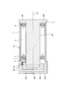
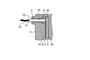
- FIG. 1 is a cross-sectional view of a stator according to an embodiment of the present invention.
- FIG. 2 is an enlarged view of the hollow terminal shown in FIG.
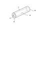
- FIG. 3 is a perspective view of the hollow terminal shown in FIG.
- the stator 100 includes a frame 1, a stator core 2, a hollow terminal 3, an insulator 4, a molding material 5, a printed circuit board 6, and a winding 7.
- An axial direction in which the central axis AX of the stator core 2 extends is indicated by an arrow D1 in FIG.
- the axial direction D1 of the central axis AX may be simply referred to as the axial direction.
- the frame 1 is a tubular member.
- the material of the frame 1 can be exemplified by copper alloy, cast iron, steel, iron alloy, aluminum alloy, or austenitic stainless alloy.
- the stator core 2 provided on the inner side of the frame 1 is configured by axially laminating a plurality of thin plates punched in an annular shape from an electromagnetic steel sheet base material. The plurality of thin plates are mutually fixed by caulking, welding or bonding.
- the stator core 2 is configured of a cylindrical core back and a plurality of teeth extending from the inner side of the core back toward the central axis AX.
- stator core 2 is not limited to what was comprised by laminating
- the laminate may be annularly arranged in the rotational direction of the central axis AX.
- An insulator 4 is provided around the stator core 2.
- the material of the insulator 4 include insulating resins such as polybutylene terephthalate, polyphenylene sulfide or liquid crystal polymer.
- the magnet wire is composed of a conductive wire and an insulator provided on the surface of the wire.
- the material of the said electric wire can illustrate copper or a copper alloy. In FIG. 1, among the magnet wires, only one end connected to the printed circuit board 6 is shown as a winding 7.
- the printed circuit board 6 is provided at a position spaced apart from the insulator 4 in the axial direction by a predetermined distance.
- the shape of the printed circuit board 6 may be an annular shape continuing in the rotational direction of the central axis AX, or may be a square plate shape. As shown in FIG. 2, one substrate surface 62 of the printed circuit board 6 is disposed on the insulator 4 side, and the other substrate surface 61 of the printed substrate 6 is disposed on the opposite side of the printed circuit board 6 to the insulator 4 side.
- the insulator 4 is provided with a binding pin (not shown), and the end of the winding 7 is connected to the pattern wiring 61a on the printed circuit board 6 shown in FIG. 2 after being wound around the binding pin Ru.
- the binding pin is used to bind and bind the winding start portion of the magnet wire when starting winding the magnet wire to the stator core 2, and for binding and bundling the wound end portion of the magnet wire wound around the stator core 2. It is a winding pin for winding end.
- the winding start portion of the magnet wire and the winding end portion of the magnet wire correspond to the end of the winding 7.
- the pattern wiring 61a can be exemplified by a wiring for supplying power to the winding 7.
- the pattern wiring 61a is not limited to this, and is provided on the printed circuit board 6 for detecting the temperature of the stator 100, for example.
- the pattern wiring 61 a is provided on the substrate surface 61 on the opposite side of the printed circuit board 6 to the insulator 4 side, but the pattern wiring 61 a should electrically connect the hollow terminal 3 and the winding 7. If it is possible, it may be provided on the substrate surface 62 of the printed circuit board 6 on the insulator 4 side. Details of the configuration of the hollow terminal 3 will be described later.
- the hollow terminal 3 is a cylindrical conductive member having an inner circumferential surface 32 on which the electrical connection with the outside of the stator 100 is made.
- a cavity 31 is formed inside the hollow terminal 3.
- the cavity 31 is a space formed by the inner circumferential surface 32 of the hollow terminal 3.
- the cross-sectional shape orthogonal to the axial direction of the cavity 31 is circular.
- the shape of the hollow terminal 3 is not limited to a cylindrical shape, and may be a polygonal cylindrical shape.
- the cross section orthogonal to the axial direction of the cavity 31 can insert a conductive terminal described later, and at least a part of the surface of the terminal inserted in the cavity 31 contacts the inner circumferential surface 32 of the hollow terminal 3 It is considered as possible.
- Examples of the material of the hollow terminal 3 include copper alloy, cast iron, steel, or iron alloy.
- an axial end 33 which is the other end of the hollow terminal 3 is in contact with the substrate surface 61 of the printed circuit board 6.
- the end 33 of the hollow terminal 3 is the tip of the hollow terminal 3 on the printed circuit board 6 side.
- the end 33 of the hollow terminal 3 is fixed to the printed circuit board 6 by soldering with the end 33 opened. Specifically, in a state where the end 33 of the hollow terminal 3 is in contact with the printed circuit board 6, soldering is performed in which the solder 8 is provided between the printed circuit 6 and the outer peripheral surface 39 near the end 33 of the hollow terminal 3 Thus, the hollow terminal 3 is fixed to the printed circuit board 6. Thereby, the hollow terminal 3 is electrically connected to the winding 7 shown in FIG. 1 through the solder 8 and the pattern wiring 61a.
- connection of the hollow terminal 3 to the pattern wiring 61a may be performed by brazing or welding other than soldering, as long as the pattern wiring 61a and the hollow terminal 3 are electrically connected.
- the end 33 of the hollow terminal 3 is in contact with the substrate surface 61 of the printed board 6, but the hollow 33 is hollow by inserting the end 33 of the hollow terminal 3 into the through hole formed in the printed board 6.
- the terminal 3 may be fixed to the printed circuit board 6.
- the positional deviation of the hollow terminal 3, particularly the positional deviation of the hollow terminal 3 in the direction orthogonal to the axial direction is suppressed, so soldering, brazing or The work at the time of connecting hollow terminal 3 to pattern wiring 61a by welding is facilitated.
- an end portion 33 of the hollow terminal 3 may be provided with a projecting portion extending in the radial direction from the end portion 33 of the hollow terminal 3.
- An axial end 34 which is one end of the hollow terminal 3 is open so that a conductive terminal described later can be inserted.
- the inner peripheral surface 32 of the hollow terminal 3 is exposed from the projecting molding material 51 and is opened from the end 34 of the hollow terminal 3 to the outside of the projecting molding material 51.
- the end 34 of the hollow terminal 3 is the tip of the hollow terminal 3 on the opposite side to the printed circuit board 6 side, and is exposed on the surface of the projecting shaped material 51.
- the cut end of the projecting molding 51 is attached to the end 34 of the hollow terminal 3
- electrical connection between the conductive terminal described later and the hollow terminal 3 is possible.
- the number of hollow terminals 3 is not limited to one, and may be plural.
- a plurality of pattern wirings 61 a corresponding to the number of hollow terminals 3 are provided on the printed circuit board 6.
- the direction in which the hollow terminal 3 extends is not limited to the direction parallel to the axial direction, and may be inclined at a constant angle with respect to the axial direction.
- Molding material 5 includes stator core 2, hollow terminal 3, solder 8, pattern wiring 61 a on printed circuit board 6, substrate surface 61 of printed circuit board 6, substrate surface 62 of printed circuit board 6, and insulator 4. It is formed of a thermosetting resin that covers it.
- the material of the molding material 5 can be exemplified by unsaturated polyester resin, vinyl ester resin, epoxy resin or phenol resin, varnish resin or silicone resin.
- FIG. 4 is a view showing a manufacturing process of the stator shown in FIG.
- FIG. 5 is a view showing a state in which the stator assembly composed of the stator core shown in FIG. 1 and the like is housed in the upper and lower molds.
- FIG. 6 is a view showing a state in which the resin is injected into the upper mold and the lower mold shown in FIG.
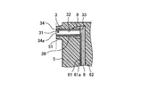
- FIG. 7 is an enlarged view of the hollow terminal immediately after the upper mold shown in FIG. 6 is removed.
- FIG. 8 is an enlarged view of the hollow terminal after the bottom portion is removed together with a part of the projecting molding shown in FIG.
- FIG. 9 is a view showing the hollow terminal shown in FIG. 8 in which the terminal is inserted.
- step 1 When manufacturing the stator 100 shown in FIG. 1, in step 1, the conductive bottomed cylindrical terminal 3 ⁇ / b> A, the stator core 2, and the frame 1 are manufactured. Details of a method of manufacturing the bottomed cylindrical terminal 3A will be described later.
- step 2 the bottomed cylindrical terminal 3 ⁇ / b> A is fixed to the printed circuit board 6 by soldering while the end 33 of the cylindrical bottomed terminal 3 ⁇ / b> A is in contact with the printed circuit board 6.
- step 2 the insulator 4 is assembled to the stator core 2.
- the winding 7 is formed by winding the magnet wire in a coil shape around the stator core 2 through the insulator 4.
- the stator core 2 having the windings 7 is press-fit, shrink-fit or cold-fit into the frame 1, thereby integrating the stator core 2 and the frame 1.
- step 5 of FIG. 4 the lower mold 200 is fitted into the integrated stator core 2 and frame 1.
- the lower mold core rod 201 of the lower mold 200 is inserted into the stator core 2 and one axial end 11 of the frame 1 contacts the mounting plate 202 of the lower mold 200, the stator core 2 and The fitting of the lower mold 200 into the frame 1 is completed.
- the printed circuit board 6 is placed to face the insulator 4 in step 6 of FIG. 4.
- a metal or resin base component is manufactured in advance, and the base component is assembled to the insulator 4 or the stator core 2, and the printed circuit board 6 is assembled to the base component assembled to the insulator 4 or the stator core 2.
- the upper mold 300 is fitted into the stator assembly 101.
- the upper mold 300 is formed with a recessed gate 301 into which the end of the bottomed cylindrical terminal 3A is inserted, and a gate 302 in communication with the gate 301 for injecting the resin 5A.
- the shape of the gate 301 is such that the tip of the bottomed cylindrical terminal 3A does not contact the upper mold 300 when the insertion of the upper mold 300 into the stator assembly 101 is completed, and the shape of the bottomed cylindrical terminal 3A It is sufficient that the resin 5A covering the tip has a projecting shape.
- the tip of the bottomed cylindrical terminal 3A described here corresponds to the bottom of the bottomed cylindrical terminal 3A. Details of the bottom of the bottomed cylindrical terminal 3A will be described later.
- the resin 5A is injected into the gate 302 as shown in FIG. 6 in step 9 of FIG.
- the resin 5A injected into the gate 302 passes through the gate 301 and reaches the bottomed cylindrical terminal 3A, the printed circuit board 6, and the insulator 4 provided on the upper mold 300 side of the stator core 2. Further, resin 5A passes through the gaps between the teeth adjacent in the rotational direction of central axis AX among the plurality of teeth constituting stator core 2, and reaches insulator 4 provided on the lower mold 200 side of stator core 2.
- the bottomed cylindrical terminal 3A, the solder 8 shown in FIG. 2 the pattern wiring 61a on the printed board 6 shown in FIG.
- the board surface 61 of the printed board 6 shown in FIG. The substrate surface 62 of the printed circuit board 6 and the insulator 4 are covered with the resin 5A.
- the resin 5A By curing the resin 5A, the molding material 5 and the projecting molding material 51 shown in FIG. 7 are formed.
- the solder 8 is provided around the end of the bottomed cylindrical terminal 3A on the printed board 6 side, the end of the bottomed cylindrical terminal 3A on the printed board 6 side and the printed board by the solder 8 The gap between 6 and 6 is closed. The end of the bottomed cylindrical terminal 3A opposite to the printed circuit board 6 is closed.
- step 10 of FIG. 4 the upper mold 300 shown in FIG. 6 is removed.
- the shape of the bottomed cylindrical terminal 3A immediately after the upper mold 300 is removed is a bottomed cylindrical shape as shown in FIG.
- the bottomed cylindrical terminal 3A is formed of a hollow cylindrical portion 36 and a bottom portion 35 provided at one end of the cylindrical portion 36, and is formed by drawing a thin metal plate, for example.
- the bottomed cylindrical terminal 3 ⁇ / b> A configured in this manner is covered with the molding material 5 and the protruding molding material 51 at locations other than the portion covered by the solder 8.
- the outer peripheral surface 39 of the cylindrical portion 36 of the bottomed cylindrical terminal 3A is covered with the molding material 5 and the protruding molding material 51, and the surface of the bottom portion 35 of the bottomed cylindrical terminal 3A is the protruding molding material 51. It is covered with The protruding molding material 51 is obtained by curing a part of the resin 5A filled in the gap between the gate 301 and the bottomed cylindrical terminal 3A shown in FIG.
- step 11 of FIG. 4 a part of the projecting molding 51 shown in FIG. 7 and the bottom 35 are removed by cutting. That is, the bottom portion 35 of the bottomed cylindrical terminal 3A covered with the projecting shaped material 51 is removed together with the projecting shaped material 51.
- the part shown by the broken line shown in FIG. 8 is the part to be cut.
- the end 34 of the hollow terminal 3 is exposed on the surface of the projecting molded material 51 remaining without being removed, and the opening 34 a is formed in the exposed end 34 of the hollow terminal 3.
- the end face of the end portion 34 of the hollow terminal 3 and a part of the outer peripheral surface of the projecting shaped material 51 constitute the same flat surface.
- the stator 100 shown in FIG. 1 is completed.
- a rotor, a plurality of bearings for rotatably supporting a shaft provided on the rotor, and a flange in which respective outer rings of the plurality of bearings are fitted and fixed to the frame 1 are assembled in order .
- a conductive terminal 10 is inserted into the cavity 31 of the hollow terminal 3 as shown in FIG.
- a material of the terminal copper or a copper alloy can be exemplified.
- the shape of the terminal 10 may be cylindrical or polygonal.
- Wires 12 extending from devices provided on the outside of the stator 100 are connected to the terminals 10.
- the said apparatus is a power converter device which supplies electric power to the winding 7 of the stator 100, for example.
- the wiring 12 is electrically connected to the winding 7 shown in FIG. 1 through the terminal 10, the hollow terminal 3, the solder 8 and the pattern wiring 61 a.
- the wire 12 extending from an external device is electrically connected to the hollow terminal 3 through the terminal 10, but instead of using the terminal 10, the wire 12 is directly inserted into the hollow terminal 3
- the wire 12 is a single wire
- the cross section of the single wire wire 12 can be inserted into the cavity 31 of the hollow terminal 3 shown in FIG. 8 and at least a part of the outer peripheral surface of the wire 12 is inside the hollow terminal 3 It is made into the magnitude
- FIG. By inserting such a wire 12 into the hollow terminal 3, the wire 12 is electrically connected to the winding 7 shown in FIG. 1 via the hollow terminal 3, the solder 8 and the pattern wire 61 a.
- the voltage output from the power conversion device is applied to the winding 7, and a current flows through the winding 7, generating a magnetic field between the rotor and the stator core 2 shown in FIG.
- a permanent magnet is used for the rotor, an electromagnetic force is generated by the interaction between the magnetic field generated by the permanent magnet and the aforementioned magnetic field, and the rotor is rotated by the electromagnetic force.
- the terminal for connecting the wire extending from the device outside the stator does not have a hollow structure, a part of the terminal is exposed to the outside of the molding material formed by curing of the resin.
- the sealing agent is attached to the terminal, and after the resin filling is completed, the sealing agent is removed, and the resin hardens part of the terminal.
- bottomed cylindrical terminal 3A is used as shown in FIG.
- the tip of the bottomed cylindrical terminal 3A covered with the molding material 5 formed by curing the resin 5A is formed without curing the bottomed cylindrical terminal 3A using a insert or the like when filling the resin 5A.
- the cavity 31 of the hollow terminal 3 can be exposed to the outside of the molding material 5 only by removing the molding material 51 together with the molding material 51. Therefore, the wiring 12 and the hollow terminal 3 can be electrically connected only by inserting the wiring 12 or the terminal 10 into the cavity 31 of the hollow terminal 3 without performing operations such as welding. Therefore, the work for electrically connecting the wire 12 to the hollow terminal 3 is simplified, and the productivity of the stator 100 is improved.
- the frequency of occurrence of connection failure is reduced as compared to the case where welding or the like is performed, it is possible to reduce the risk that the connection failure occurs at the time of manufacturing the stator 100 and the yield decreases.
- the occurrence frequency of connection failure is reduced, it is possible to reduce the risk that the wire 12 is detached from the hollow terminal 3 and the motor is stopped during operation of the motor provided with the stator 100.
- a device for performing welding or the like is not necessary, and the manufacturing cost of the stator 100 can be reduced.
- the hollow terminal 3 is hollow outside the molding material 5 only by removing the tip of the bottomed cylindrical terminal 3A covered with the molding material 5 together with the projecting molding material 51. Since 31 can be exposed, the connection portion between the hollow terminal 3 and the wiring 12 or the terminal 10 can be easily formed. Further, in stator 100 according to the present embodiment, even if the mold is not processed according to the shape of the insert, etc., a simple-shaped recessed gate 301 in which the end of hollow terminal 3 is inserted is provided in the mold. The shape of the mold can be simplified because it is sufficient.
- a solid conductive terminal is a columnar terminal in which a conductor is packed inside. Therefore, a holding mechanism is required to hold the state in which the wire 12 is pressed against the tip of the solid conductive terminal.
- the holding mechanism may be integrated with the stator or may be removable from the stator, but in any case, it is necessary to manufacture the holding mechanism, attach the holding mechanism to the stator before connection, etc. Therefore, the productivity of the stator decreases and the manufacturing cost of the stator increases.
- the outer dimensions of the stator may be larger than in the stator 100 according to the present embodiment which does not include the holding mechanism, and the installation location of the stator may be restricted. is there.
- wiring 12 or terminal 10 is connected to hollow terminal 3 simply by inserting wiring 12 or terminal 10 into cavity 31 of hollow terminal 3 without using the above holding mechanism.
- productivity of the stator 100 can be improved, and the manufacturing cost of the stator 100 can be reduced.
- the manufacturing time of a stator requires a long time, and the subject that productivity of a stator falls occurs.
- the stator 100 of the present embodiment after the tip of the hollow terminal 3 covered with the molding material 5 is removed together with the projecting molding material 51, the hollow 31 of the hollow terminal 3 exposed to the outside of the molding material 5 is removed. The wiring 12 or the terminal 10 may be connected. Therefore, the manufacturing time of the stator 100 can be shortened as compared with the case where the lead wire is connected to the solid conductive terminal in advance.
- bottomed cylindrical terminal 3A in step 1 shown in FIG. 4 is demonstrated.
- the bottomed cylindrical terminal 3A may have any structure as long as the resin 5A injected into the mold does not penetrate into the inside of the bottomed cylindrical terminal 3A. Can be illustrated.
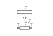
- FIG. 10 is a diagram for explaining a first method of manufacturing the hollow terminal shown in FIG.
- the cylindrical member 30 shown in FIG. 10 is a conductive hollow pipe, and an opening formed at the end of the cylindrical member 30 by crushing the end of the cylindrical member 30 by header processing, press processing or the like. Is closed, and the bottomed cylindrical terminal 3A provided with the closed portion 30a is manufactured.
- the closed portion 30a corresponds to the bottom portion 35 shown in FIG.
- the resin 5A injected into the mold can be prevented from infiltrating the inside of the cylindrical member 30.
- the bottomed cylindrical terminal 3A can be easily manufactured using the existing processing apparatus.
- the closing portion 30a may be provided on only one side of the cylindrical member 30.
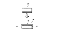
- FIG. 11 is a view for explaining a second method of manufacturing the hollow terminal shown in FIG.
- the cylindrical member 30 shown in FIG. 11 is a conductive hollow pipe. By heating and melting the end of the cylindrical member 30 to a high temperature, the opening formed at the end of the cylindrical member 30 is closed, and the bottomed cylindrical terminal 3A provided with the fusing part 37 is manufactured. Ru.
- the fusing part 37 corresponds to the bottom part 35 shown in FIG. By providing the fusing part 37, it is possible to prevent the resin 5A injected into the mold from entering the inside of the cylindrical member 30.
- the fusing part 37 may be formed by cutting the end of the cylindrical member 30 with a laser. According to the manufacturing method shown in FIG.
- the bottomed cylindrical terminal 3A can be manufactured simply by melting the end of the cylindrical member 30 without using an apparatus for processing the header and the like.
- the fusing part 37 may be provided only on one side of the cylindrical member 30.
- FIG. 12 is a diagram for explaining a third method of manufacturing the hollow terminal shown in FIG.
- the cylindrical member 30 shown in FIG. 12 is a conductive hollow pipe.
- the closing member 38 is a member for closing the opening formed at the end of the cylindrical member 30, and corresponds to the bottom 35 shown in FIG.
- the material of the closing member 38 may be any material that does not melt due to the heat of the resin 5A injected into the mold, and the material of the closing member 38 can be exemplified by an adhesive, a tape, a metal piece or a resin piece.
- the metal pieces or the resin pieces may be, for example, scraps produced in the manufacturing process of the stator 100.
- the closing member 38 By providing the closing member 38, it is possible to prevent the resin 5A injected into the mold from entering the inside of the cylindrical member 30.
- the apparatus for processing the header or the like, a tool for melting the end of the cylindrical member 30, etc. are not used, and the end of the cylindrical member 30 is simply provided with the closing member 38.
- the cylindrical terminal 3A can be manufactured.
- the closing member 38 may be provided on only one side of the cylindrical member 30.
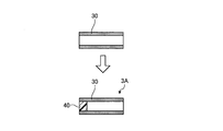
- FIG. 13 is a view for explaining a fourth method of manufacturing the hollow terminal shown in FIG.
- the cylindrical member 30 shown in FIG. 13 is a conductive hollow pipe.
- the bottomed cylindrical terminal 3A is manufactured by filling the inside of the cylindrical member 30 with the filler 40 so as to close the cavity formed inside the cylindrical member 30.
- the filler 40 is filled only on one end side of the cylindrical member 30.
- the material of the filler 40 is silicone resin or the like, but does not melt by the heat of the resin 5A injected into the mold, and the bottomed cylindrical terminal when inserting the wire 12 or the terminal 10 shown in FIG. It may be a fluid material discharged to the outside of 3A, and is not limited to silicone resin.
- the filler 40 corresponds to the bottom 35 shown in FIG.
- the filler 40 By providing the filler 40, it is possible to prevent the resin 5A injected into the mold from intruding into the inside of the cylindrical member 30 from one end side of the cylindrical member 30.
- the bottom of the cylindrical member 30 is filled only by filling the filler 40 without using an apparatus for processing the header, a tool for melting the end of the cylindrical member 30, and the like.
- the cylindrical terminal 3A can be manufactured.
- the filler 40 is filled only at one end side of the cylindrical member 30, and the other end of the cylindrical member 30 is not filled with the filler 40. Even in this configuration, the other end of the cylindrical member 30 shown in FIG. 13 is in contact with the printed circuit board 6 shown in FIG. Thereby, the resin 5A can be prevented from intruding into the inside of the cylindrical member 30 from the other end of the cylindrical member 30.
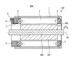
- FIG. 14 is a cross-sectional view of a motor according to an embodiment of the present invention.
- a motor 500 shown in FIG. 14 includes the stator 100 and the rotor 400 shown in FIG.
- the motor 500 is a synchronous motor or an induction motor.
- the rotor 400 includes a cylindrical rotor core 401 and a shaft 402 penetrating the rotor core 401 in the axial direction.
- the rotor 400 includes, in addition to the rotor core 401 and the shaft 402, a plurality of bearings rotatably supporting the shaft 402, and a flange.
- the illustration of the bearing and the flange is omitted in FIG.
- the flange is an annular member fixed to the end of the frame 1.
- the outer periphery of the bearing is fixed at the radial center of the flange.
- the rotor 400 is rotatably supported inside the stator 100.
- the end of the wiring 12 or the terminal 10 is connected near the end of the conductive terminal, so the contact area is small.
- the inner peripheral surface of the hollow terminal 3 and the outer periphery of the wire or terminal inserted in the hollow terminal 3 are compared to the case of using the solid conductive terminal.
- the contact area with the surface is increased. Therefore, the electrical resistance at the contact portion is reduced, and the motor efficiency and the motor output are improved.
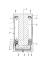
- FIG. 15 is a cross-sectional view of a stator according to a modification of the embodiment of the present invention.
- the hollow terminal 3 is fixed to the insulator 4 by inserting the end of the hollow terminal 3 on the insulator 4 side into the insulator 4 by press fitting or the like.
- the other configuration is the same as or equivalent to the configuration of stator 100 shown in FIG. 1, and the same or equivalent components are denoted by the same reference numerals and redundant description will be omitted.
- the printed circuit board 6 shown in FIG. 1 is not shown.
- one previously connected to the wire 12 extending from the device outside the terminal 10 may be used, or one previously provided on the stators 100 and 100A may be used. .
- the hollow terminal 3 or the bottomed cylindrical terminal 3A is provided in the position near the radial direction outer side of the printed circuit board 6, the position where the hollow terminal 3 or the bottomed cylindrical terminal 3A is provided is the bottom portion 35.
- the present invention is not limited to this as long as the surface can be covered with the resin 5A and the molding material 5 covering the surface of the bottom 35 can be removed together with the bottom 35.
- the hollow terminal 3 or the bottomed cylindrical terminal 3 ⁇ / b> A may be provided at the radially inward position of the printed board 6 or at the radially inward position of the insulator 4.
- the configuration shown in the above embodiment shows an example of the contents of the present invention, and can be combined with another known technique, and one of the configurations is possible within the scope of the present invention. Parts can be omitted or changed.
Landscapes
- Engineering & Computer Science (AREA)
- Power Engineering (AREA)
- Manufacturing & Machinery (AREA)
- Manufacture Of Motors, Generators (AREA)
- Insulation, Fastening Of Motor, Generator Windings (AREA)
- Motor Or Generator Frames (AREA)
- Iron Core Of Rotating Electric Machines (AREA)
Priority Applications (7)
| Application Number | Priority Date | Filing Date | Title |
|---|---|---|---|
| US16/762,514 US10992210B2 (en) | 2018-01-29 | 2018-01-29 | Stator, motor, and stator manufacturing method |
| CN201880087746.7A CN111656648B (zh) | 2018-01-29 | 2018-01-29 | 定子及电动机 |
| JP2018565079A JP6498372B1 (ja) | 2018-01-29 | 2018-01-29 | ステータ、モータ及びステータの製造方法 |
| DE112018006419.0T DE112018006419T5 (de) | 2018-01-29 | 2018-01-29 | Stator, motor und statorherstellungsverfahren |
| KR1020207017445A KR102153382B1 (ko) | 2018-01-29 | 2018-01-29 | 스테이터, 모터 및 스테이터의 제조 방법 |
| PCT/JP2018/002750 WO2019146108A1 (ja) | 2018-01-29 | 2018-01-29 | ステータ、モータ及びステータの製造方法 |
| TW108102252A TWI692180B (zh) | 2018-01-29 | 2019-01-21 | 定子、馬達及定子的製造方法 |
Applications Claiming Priority (1)
| Application Number | Priority Date | Filing Date | Title |
|---|---|---|---|
| PCT/JP2018/002750 WO2019146108A1 (ja) | 2018-01-29 | 2018-01-29 | ステータ、モータ及びステータの製造方法 |
Publications (1)
| Publication Number | Publication Date |
|---|---|
| WO2019146108A1 true WO2019146108A1 (ja) | 2019-08-01 |
Family
ID=66092574
Family Applications (1)
| Application Number | Title | Priority Date | Filing Date |
|---|---|---|---|
| PCT/JP2018/002750 WO2019146108A1 (ja) | 2018-01-29 | 2018-01-29 | ステータ、モータ及びステータの製造方法 |
Country Status (7)
| Country | Link |
|---|---|
| US (1) | US10992210B2 (ko) |
| JP (1) | JP6498372B1 (ko) |
| KR (1) | KR102153382B1 (ko) |
| CN (1) | CN111656648B (ko) |
| DE (1) | DE112018006419T5 (ko) |
| TW (1) | TWI692180B (ko) |
| WO (1) | WO2019146108A1 (ko) |
Families Citing this family (1)
| Publication number | Priority date | Publication date | Assignee | Title |
|---|---|---|---|---|
| MX2023000269A (es) * | 2020-07-07 | 2023-02-09 | Nippon Steel Corp | Metodo de fabricacion de nucleo laminado adhesivamente y dispositivo de fabricacion de nucleo laminado adhesivamente. |
Citations (6)
| Publication number | Priority date | Publication date | Assignee | Title |
|---|---|---|---|---|
| US3350587A (en) * | 1965-03-31 | 1967-10-31 | Vincent K Smith | Electrical plug and connector |
| JPS616805A (ja) * | 1984-05-29 | 1986-01-13 | ゼネラル モーターズ コーポレーシヨン | 端子装置、ソレノイド及びソレノイドの製造方法 |
| JP2875666B2 (ja) * | 1991-11-18 | 1999-03-31 | 松下精工株式会社 | 樹脂モールドモータの固定子 |
| JP2005080445A (ja) * | 2003-09-02 | 2005-03-24 | Yaskawa Electric Corp | モールドモータのリード線引出し構造 |
| JP2011146230A (ja) * | 2010-01-14 | 2011-07-28 | Toyota Motor Corp | 端末接続装置 |
| JP2014180191A (ja) * | 2013-02-18 | 2014-09-25 | Nidec Techno Motor Corp | モータ |
Family Cites Families (13)
| Publication number | Priority date | Publication date | Assignee | Title |
|---|---|---|---|---|
| US4586245A (en) * | 1984-05-29 | 1986-05-06 | General Motors Corporation | Solenoid coil wire termination |
| US4926545A (en) * | 1989-05-17 | 1990-05-22 | At&T Bell Laboratories | Method of manufacturing optical assemblies |
| JP3730461B2 (ja) * | 1999-10-28 | 2006-01-05 | 山洋電気株式会社 | 防水型ブラシレスファンモータ |
| JP2001352705A (ja) * | 2000-06-12 | 2001-12-21 | Matsushita Electric Ind Co Ltd | スピンドルモータ |
| JP3930340B2 (ja) * | 2002-02-25 | 2007-06-13 | ミネベア株式会社 | 回転電機 |
| JP4425045B2 (ja) * | 2004-04-14 | 2010-03-03 | 三菱電機株式会社 | レゾルバ |
| JP4931449B2 (ja) * | 2006-03-22 | 2012-05-16 | 日本電産サンキョー株式会社 | モータ |
| JP5389559B2 (ja) * | 2009-07-23 | 2014-01-15 | 愛三工業株式会社 | 回転電動機の固定子及び燃料ポンプ |
| TWI612759B (zh) * | 2012-03-29 | 2018-01-21 | 荏原製作所股份有限公司 | 密封電動機、真空泵 |
| JP5745477B2 (ja) * | 2012-08-10 | 2015-07-08 | 三菱電機株式会社 | 電動機の固定子、電動機および設備機器 |
| WO2015182346A1 (ja) * | 2014-05-26 | 2015-12-03 | 三菱電機株式会社 | 回転電機および回転電機の製造方法 |
| JP6480797B2 (ja) * | 2014-07-08 | 2019-03-13 | Kyb株式会社 | ステータユニット、ステータユニットを備える回転電機及びステータユニットの製造方法 |
| JP2017085843A (ja) * | 2015-10-30 | 2017-05-18 | 日本電産テクノモータ株式会社 | ステータ、モータ及びステータの製造方法 |
-
2018
- 2018-01-29 WO PCT/JP2018/002750 patent/WO2019146108A1/ja active Application Filing
- 2018-01-29 US US16/762,514 patent/US10992210B2/en active Active
- 2018-01-29 JP JP2018565079A patent/JP6498372B1/ja active Active
- 2018-01-29 CN CN201880087746.7A patent/CN111656648B/zh active Active
- 2018-01-29 KR KR1020207017445A patent/KR102153382B1/ko active IP Right Grant
- 2018-01-29 DE DE112018006419.0T patent/DE112018006419T5/de active Pending
-
2019
- 2019-01-21 TW TW108102252A patent/TWI692180B/zh active
Patent Citations (6)
| Publication number | Priority date | Publication date | Assignee | Title |
|---|---|---|---|---|
| US3350587A (en) * | 1965-03-31 | 1967-10-31 | Vincent K Smith | Electrical plug and connector |
| JPS616805A (ja) * | 1984-05-29 | 1986-01-13 | ゼネラル モーターズ コーポレーシヨン | 端子装置、ソレノイド及びソレノイドの製造方法 |
| JP2875666B2 (ja) * | 1991-11-18 | 1999-03-31 | 松下精工株式会社 | 樹脂モールドモータの固定子 |
| JP2005080445A (ja) * | 2003-09-02 | 2005-03-24 | Yaskawa Electric Corp | モールドモータのリード線引出し構造 |
| JP2011146230A (ja) * | 2010-01-14 | 2011-07-28 | Toyota Motor Corp | 端末接続装置 |
| JP2014180191A (ja) * | 2013-02-18 | 2014-09-25 | Nidec Techno Motor Corp | モータ |
Also Published As
| Publication number | Publication date |
|---|---|
| JPWO2019146108A1 (ja) | 2020-02-06 |
| DE112018006419T5 (de) | 2020-08-27 |
| US10992210B2 (en) | 2021-04-27 |
| US20200395826A1 (en) | 2020-12-17 |
| CN111656648A (zh) | 2020-09-11 |
| TWI692180B (zh) | 2020-04-21 |
| CN111656648B (zh) | 2021-04-27 |
| TW201933730A (zh) | 2019-08-16 |
| KR102153382B1 (ko) | 2020-09-08 |
| JP6498372B1 (ja) | 2019-04-10 |
| KR20200079549A (ko) | 2020-07-03 |
Similar Documents
| Publication | Publication Date | Title |
|---|---|---|
| CN109643940B (zh) | 层叠铁芯、层叠铁芯的制造方法及使用层叠铁芯的电枢 | |
| JP4797728B2 (ja) | 回転電機の固定子、固定子に用いられる部品および回転電機の固定子の製造方法 | |
| US10855132B2 (en) | Bus bar unit, rotary electric machine having the same, and manufacturing method of bus bar unit | |
| CN107846099B (zh) | 定子及制造定子的方法 | |
| JP5872807B2 (ja) | モータにおけるコイル巻線の結線構造およびモータ | |
| JP4772070B2 (ja) | ポンプ用電動機の固定子及びポンプ用電動機及びポンプ | |
| JP6973395B2 (ja) | モータ | |
| CN109792187B (zh) | 用于使电机的绕组与印刷电路板电接触的方法 | |
| JP2007209100A (ja) | ブスバーおよびモータ | |
| WO2017018066A1 (ja) | モータおよびモータの製造方法 | |
| JP4735691B2 (ja) | モータの製造方法 | |
| JP2018207582A (ja) | 静止部、モータ、およびモータの製造方法 | |
| WO2019146108A1 (ja) | ステータ、モータ及びステータの製造方法 | |
| JP5319407B2 (ja) | 圧入装置及びアキシャルギャップ型回転電機のステータの製造方法 | |
| JP2007028824A (ja) | 整流子及び電機子 | |
| WO2018062351A1 (ja) | モータ | |
| JP2018135909A (ja) | 接合部材、接合方法および回転電機 | |
| CN111066227B (zh) | 旋转电机的定子及定子的制造方法 | |
| JP5781239B2 (ja) | 回転電機の回転子およびその製造方法 | |
| JP2020014366A (ja) | ステータ及びステータ製造方法 | |
| JP4704834B2 (ja) | 整流子及び電機子 | |
| JP7134457B2 (ja) | ブラシレスモータ | |
| JP2002051519A (ja) | ブラシレスモータおよびその製造方法 | |
| JP2015006016A (ja) | 回転電機及び回転電機の製造方法 | |
| JP2020072578A (ja) | モータ |
Legal Events
| Date | Code | Title | Description |
|---|---|---|---|
| ENP | Entry into the national phase |
Ref document number: 2018565079 Country of ref document: JP Kind code of ref document: A |
|
| 121 | Ep: the epo has been informed by wipo that ep was designated in this application |
Ref document number: 18902332 Country of ref document: EP Kind code of ref document: A1 |
|
| ENP | Entry into the national phase |
Ref document number: 20207017445 Country of ref document: KR Kind code of ref document: A |
|
| 122 | Ep: pct application non-entry in european phase |
Ref document number: 18902332 Country of ref document: EP Kind code of ref document: A1 |