WO2017018066A1 - モータおよびモータの製造方法 - Google Patents
モータおよびモータの製造方法 Download PDFInfo
- Publication number
- WO2017018066A1 WO2017018066A1 PCT/JP2016/067011 JP2016067011W WO2017018066A1 WO 2017018066 A1 WO2017018066 A1 WO 2017018066A1 JP 2016067011 W JP2016067011 W JP 2016067011W WO 2017018066 A1 WO2017018066 A1 WO 2017018066A1
- Authority
- WO
- WIPO (PCT)
- Prior art keywords
- terminal pin
- motor
- recess
- casing
- motor according
- Prior art date
Links
Images


Classifications
-
- H—ELECTRICITY
- H02—GENERATION; CONVERSION OR DISTRIBUTION OF ELECTRIC POWER
- H02K—DYNAMO-ELECTRIC MACHINES
- H02K3/00—Details of windings
- H02K3/46—Fastening of windings on the stator or rotor structure
- H02K3/50—Fastening of winding heads, equalising connectors, or connections thereto
-
- H—ELECTRICITY
- H02—GENERATION; CONVERSION OR DISTRIBUTION OF ELECTRIC POWER
- H02K—DYNAMO-ELECTRIC MACHINES
- H02K15/00—Methods or apparatus specially adapted for manufacturing, assembling, maintaining or repairing of dynamo-electric machines
- H02K15/0056—Manufacturing winding connections
- H02K15/0068—Connecting winding sections; Forming leads; Connecting leads to terminals
- H02K15/0081—Connecting winding sections; Forming leads; Connecting leads to terminals for form-wound windings
-
- H—ELECTRICITY
- H02—GENERATION; CONVERSION OR DISTRIBUTION OF ELECTRIC POWER
- H02K—DYNAMO-ELECTRIC MACHINES
- H02K15/00—Methods or apparatus specially adapted for manufacturing, assembling, maintaining or repairing of dynamo-electric machines
- H02K15/04—Methods or apparatus specially adapted for manufacturing, assembling, maintaining or repairing of dynamo-electric machines of windings, prior to mounting into machines
- H02K15/0435—Wound windings
-
- H—ELECTRICITY
- H02—GENERATION; CONVERSION OR DISTRIBUTION OF ELECTRIC POWER
- H02K—DYNAMO-ELECTRIC MACHINES
- H02K15/00—Methods or apparatus specially adapted for manufacturing, assembling, maintaining or repairing of dynamo-electric machines
- H02K15/14—Casings; Enclosures; Supports
-
- H—ELECTRICITY
- H02—GENERATION; CONVERSION OR DISTRIBUTION OF ELECTRIC POWER
- H02K—DYNAMO-ELECTRIC MACHINES
- H02K3/00—Details of windings
- H02K3/04—Windings characterised by the conductor shape, form or construction, e.g. with bar conductors
- H02K3/28—Layout of windings or of connections between windings
-
- H—ELECTRICITY
- H02—GENERATION; CONVERSION OR DISTRIBUTION OF ELECTRIC POWER
- H02K—DYNAMO-ELECTRIC MACHINES
- H02K5/00—Casings; Enclosures; Supports
- H02K5/02—Casings or enclosures characterised by the material thereof
-
- H—ELECTRICITY
- H02—GENERATION; CONVERSION OR DISTRIBUTION OF ELECTRIC POWER
- H02K—DYNAMO-ELECTRIC MACHINES
- H02K7/00—Arrangements for handling mechanical energy structurally associated with dynamo-electric machines, e.g. structural association with mechanical driving motors or auxiliary dynamo-electric machines
- H02K7/14—Structural association with mechanical loads, e.g. with hand-held machine tools or fans
-
- H—ELECTRICITY
- H02—GENERATION; CONVERSION OR DISTRIBUTION OF ELECTRIC POWER
- H02K—DYNAMO-ELECTRIC MACHINES
- H02K7/00—Arrangements for handling mechanical energy structurally associated with dynamo-electric machines, e.g. structural association with mechanical driving motors or auxiliary dynamo-electric machines
- H02K7/003—Couplings; Details of shafts
Definitions
- the present invention relates to a motor and a method for manufacturing the motor.
- the molding die presses the upper end portion of the winding terminal locking portion when the resin mold stator is manufactured. For this reason, there is a possibility that problems such as peeling of the solder, damage to the winding terminal locking portion, loosening of the winding, etc. may occur due to contact with the molding die.
- An object of the present invention is to provide a technique capable of preventing a lead wire wound around a terminal pin from coming into contact with a mold during molding of a casing in an inner rotor type or outer rotor type molded motor.
- An exemplary first invention of the present application is a motor, comprising: a stationary part including a stator; and a rotating part including a rotor that is opposed to the stationary part in a radial direction and rotates about a central axis extending vertically.
- the stationary portion includes an annular core back and a stator core having a plurality of teeth projecting radially from the core back, an insulator that covers at least a part of the stator core, and a winding wound around the teeth via the insulator.
- the casing has a concave portion that is recessed in the axial direction, and at least a portion of the terminal pin is in the concave portion.
- the conductor includes a first conductor portion located in a slit provided in said base portion, connected to the first conductor portion, having a second conductor portion that is wound in the lower portion of the terminal pin.
- An exemplary second invention of the present application is a method of manufacturing a motor in which an insulator is interposed between a stator core and a coil, and the stator core, the coil, and the resin casing that covers the insulator are provided. Attaching the terminal pin to the upper surface of the base portion of the insulator; b) drawing the end of the conducting wire constituting the coil to the terminal pin; c) winding the conducting wire around the terminal pin; d) a step of soldering the conductive wire and the terminal pin; e) a step of preparing an upper mold and a lower mold that form a cavity inside by combining with each other; and f) a step of preparing the upper mold in the base portion.
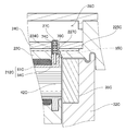
- FIG. 1 is a longitudinal sectional view of a motor according to the first embodiment.
- FIG. 2 is a cross-sectional view of the vicinity of the terminal pin according to the first embodiment.
- FIG. 3 is a perspective view showing part of the terminal pins and the insulator according to the first embodiment.
- FIG. 4 is a diagram conceptually showing the shape of the terminal pin and the conductor in the cross section according to the first embodiment.
- FIG. 5 is a diagram conceptually showing shapes of the conductive plate and the terminal pin according to the first embodiment in a top view.
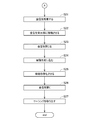
- FIG. 6 is a flowchart showing a procedure before injection molding of the casing according to the first embodiment.
- FIG. 7 is a flowchart showing a procedure at the time of injection molding of the casing according to the first embodiment.
- FIG. 8 is a view showing a state at the time of injection molding according to the first embodiment.
- FIG. 9 is a longitudinal sectional view of a motor according to the second embodiment.
- FIG. 10 is a partial cross-sectional view of a motor according to the second embodiment.
- FIG. 11 is a perspective view of a stator according to the second embodiment.
- FIG. 12 is a perspective view showing part of the terminal pins and the insulator according to the second embodiment.
- FIG. 13 is a partial cross-sectional view of the vicinity of a terminal pin according to the second embodiment.
- FIG. 14 is a top view of the casing according to the second embodiment.
- FIG. 15 is a partial cross-sectional view in the vicinity of the position detection element according to the second embodiment.
- FIG. 16 is a partial vertical cross-sectional view in the vicinity of the end of the conductive plate of the motor according to the modification.
- FIG. 17 is a top view of a conductive plate according to a modification.
- FIG. 18 is a longitudinal sectional view of the vicinity of a terminal pin of a motor according to a modification.
- FIG. 19 is a partial perspective view of a base portion, a casing, and terminal pins of a motor according to a modified example.
- FIG. 20 is a cross-sectional view showing a state during injection molding of a casing according to a modification.
- the direction parallel to the central axis of the motor is the “axial direction”
- the direction orthogonal to the central axis of the motor is the “radial direction”
- the direction along the arc centered on the central axis of the motor is the “circumferential direction”.
- the shape and positional relationship of each part will be described with the axial direction as the vertical direction and the conductive plate side as the top with respect to the stator.
- the definition of the vertical direction is not intended to limit the orientation of the motor according to the present invention during manufacture and use.
- FIG. 1 is a longitudinal sectional view of the motor 1.
- the motor 1 is a so-called inner rotor type motor in which a rotor 32 is disposed on the radially inner side of a stator 21.
- the motor 1 is used for home appliances such as an air conditioner, for example.
- the motor 1 of the present invention may be used for applications other than home appliances.
- the motor 1 of the present invention may be mounted on transportation equipment such as automobiles and railways, OA equipment, medical equipment, tools, industrial large equipment, and the like to generate various driving forces.
- the motor 1 has a stationary part 2 and a rotating part 3.
- the stationary part 2 is fixed to a frame of a device to be driven.
- the rotating unit 3 is supported so as to be rotatable with respect to the stationary unit 2.
- the stationary part 2 of the present embodiment has a stator 21, a casing 22, a cover 23, a conduction plate 24, a lower bearing part 25, an upper bearing part 26, and a terminal pin 27.
- the rotating unit 3 includes a shaft 31 and a rotor 32.
- the stator 21 is an armature that generates a magnetic flux in accordance with a drive current supplied from an external power source through the conduction plate 24.
- the stator 21 surrounds the center axis 9 extending vertically in an annular shape.
- the stator 21 includes a stator core 211, an insulator 212, and a plurality of coils 213.
- the stator core 211 has an annular core back 41 and a plurality of teeth 42 protruding radially inward from the core back 41.
- the core back 41 is disposed substantially coaxially with the central axis 9.
- the plurality of teeth 42 are arranged at equal intervals in the circumferential direction.
- a laminated steel plate is used for example.
- the insulator 212 is attached to the stator core 211.
- a resin which is an insulator is used as a material of the insulator 212.
- the insulator 212 covers at least both end surfaces of the teeth 42 in the axial direction and both surfaces in the circumferential direction.
- the coil 213 includes a conductive wire 70 wound around the teeth 42 via an insulator 212. That is, the insulator 212 is interposed between the tooth 42 and the coil 213.
- the casing 22 is a resin member that holds the stator 21 and the lower bearing portion 25.
- the casing 22 includes a wall part 221, a bottom plate part 222, and a lower bearing holding part 223.
- the wall portion 221 extends in a substantially cylindrical shape in the axial direction.
- the stator 21 is covered with a resin constituting the wall portion 221.
- a part of the stator 21 including the end face on the radially inner side of the teeth 42 is exposed from the wall portion 221.
- a rotor 32 described later is disposed inside the wall portion 221 in the radial direction.
- the bottom plate portion 222 spreads in a plate shape from the lower end of the wall portion 221 toward the inside in the radial direction.
- the bottom plate portion 222 is located on the lower side in the axial direction than the stator 21 and the rotor 32.
- the lower bearing holding part 223 extends from the inner end of the bottom plate part 222 and covers a part of the lower bearing part 25.
- the lower bearing portion 25 and the lower end portion of the shaft 31 are disposed on the radially inner side of the lower bearing holding portion 223.
- the cover 23 covers the opening at the top of the casing 22.
- the conduction plate 24 and the rotor 32 described later are accommodated in a casing constituted by the casing 22 and the cover 23.
- the cover 23 has an upper plate portion 231 and an upper bearing holding portion 232.
- the upper plate portion 231 extends substantially perpendicular to the central axis 9 on the upper side in the axial direction from the stator 21, the casing 22, the conduction plate 24, and the rotor 32.
- the upper bearing holding portion 232 extends from the inner end of the upper plate portion 231 and covers a part of the upper bearing portion 26.
- the upper bearing portion 26 and a part of the shaft 31 are disposed on the radially inner side of the upper bearing holding portion 232.
- connection hole 201 through which the lead wire 242 passes is provided in a part in the circumferential direction.
- a bushing 243 is disposed inside the connection hole 201.
- the bushing 243 has a wiring groove in contact with the end surface constituting the connection hole 201 of the casing 22 and the cover 23 and in which the lead wire 242 is disposed.
- the conductive plate 24 is a circuit board disposed substantially perpendicular to the central axis 9.
- the conduction plate 24 is disposed above the stator 21 and the rotor 32, below the cover 23, and radially inside the wall portion 221 of the casing 22.
- the lead wire 242 extending from the conduction plate 24 is drawn out of the casing 22 through the wiring groove of the bushing 243 inside the connection hole 201. Then, the end of the lead wire 242 is connected to an external power source. A current supplied from an external power source flows to the coil 213 through the lead wire 242, the conduction plate 24, and a terminal pin 27 described later.
- the lower bearing portion 25 supports the shaft 31 to be rotatable below the rotor 32.
- the upper bearing portion 26 rotatably supports the shaft 31 above the rotor 32.
- ball bearings that rotate the outer ring and the inner ring via a sphere are used.
- the outer ring of the lower bearing portion 25 is fixed to the lower bearing holding portion 223 of the casing 22.
- the outer ring of the upper bearing portion 26 is fixed to the upper bearing holding portion 232 of the cover 23.
- the inner rings of the lower bearing portion 25 and the upper bearing portion 26 are fixed to the shaft 31.
- other types of bearings such as a slide bearing and a fluid bearing may be used instead of the ball bearing.
- the shaft 31 is a columnar member that extends through the rotor 32 in the axial direction.
- the shaft 31 rotates about the central axis 9.
- the upper end portion of the shaft 31 protrudes upward from the casing 22 and the cover 23.
- a fan for an air conditioner is attached to the upper end portion of the shaft 31.
- the upper end portion of the shaft 31 may be coupled to a drive unit other than the fan via a power transmission mechanism such as a gear.
- the rotor 32 is an annular member that is fixed to the shaft 31 and rotates together with the shaft 31.
- the rotor 32 is disposed inside the stator 21 in the radial direction.
- the rotor 32 of the present embodiment is an annular member formed of a magnet-mixed plastic resin. As shown in FIG. 1, the rotor 32 includes an inner cylinder part 321, an outer cylinder part 322, and a connection part 323.
- the inner cylinder part 321 is a substantially cylindrical part fixed to the shaft 31.
- a spiral groove 311 is provided on a surface of the outer peripheral surface of the shaft 31 that is fixed to the inner cylindrical portion 321.
- the rotor 32 is formed by injection molding using the shaft 31 as an insert part. At the time of injection molding, the resin in a fluid state flows into a groove 311 provided on the outer peripheral surface of the shaft 31. Thereby, the rotor 32 is firmly fixed to the shaft 31. Further, relative rotation of the rotor 32 with respect to the shaft 31 is suppressed when the motor 1 is driven.
- the outer cylinder part 322 is a substantially cylindrical part located radially outside the inner cylinder part 321.
- the outer peripheral surface of the outer cylindrical portion 322 faces the end surface on the radially inner side of the tooth 42 with a slight gap therebetween.
- the connection part 323 is a disk-shaped part that connects the inner cylinder part 321 and the outer cylinder part 322.
- the thickness in the radial direction of the inner cylindrical portion 321 and the outer cylindrical portion 322 is the largest in the vicinity of the boundary with the connecting portion 323.
- the radial thickness of the inner cylinder part 321 and the outer cylinder part 322 is gradually reduced toward both ends in the axial direction.
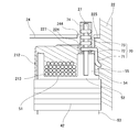
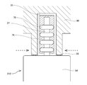
- FIG. 2 is a partial cross-sectional view of the vicinity of the terminal pin 27 of the motor 1.
- FIG. 3 is a perspective view showing a part of the terminal pin 27 and the insulator 212. In FIG. 3, illustration of the conductive wire 70 and the solder 74 is omitted.
- the insulator 212 includes a first insulating part 51, a second insulating part 52, a third insulating part 53, and a base part 54.
- the insulator 212 may be a single member or may be composed of a plurality of members.
- one or a plurality of parts of the first insulating part 51, the second insulating part 52, the third insulating part 53, and the base part 54 may be members different from other parts.
- the first insulating portion 51 covers both end surfaces of the teeth 42 in the axial direction and both surfaces in the circumferential direction.
- the second insulating portion 52 covers at least a part of the upper surface of the core back 41.
- the third insulating portion 53 covers at least a part of the lower surface of the core back 41.
- the first insulating portion 51, the second insulating portion 52, and the third insulating portion 53 are connected in the radial direction.
- the base portion 54 protrudes upward in the axial direction from the second insulating portion 52.
- a slit 55 that is recessed inward in the radial direction is provided on the side surface of the base portion 54 on the radially outer side. The slit 55 extends in the axial direction from the upper end of the base portion 54 toward the lower side.
- a terminal pin 27 is provided on the base portion 54.
- the terminal pin 27 is a columnar conductor extending in the axial direction.
- the terminal pin 27 is formed of a conductive material such as iron or copper.
- a lower end portion of the terminal pin 27 is inserted into a hole provided in the base portion 54 and fixed to the base portion 54.
- the upper end portion of the terminal pin 27 is located above the upper surface of the base portion 54.
- one terminal pin 27 is fixed to one base portion 54.
- two or more terminal pins 27 may be fixed to one base portion 54.
- the stator core 211, the insulator 212, and the coil 213 are at least partially covered by the casing 22.
- the casing 22 has a recess 224 that is recessed in the axial direction above the base portion 54 of the insulator 212.
- the upper surface of the base portion 54 is disposed in the recess 224. Accordingly, the upper surface of the base portion 54 is exposed from the casing 22. Further, at least the lower end portion of the terminal pin 27 is disposed in the recess 224 without contacting the casing 22.
- the casing 22 is obtained by injection molding in which a resin is poured into a cavity in a mold in which the stator 21 and the terminal pins 27 are accommodated to be cured. Details of the injection molding will be described later.
- the casing 22 of the present embodiment has a conductive plate arrangement surface 225 that contacts the lower surface of the conductive plate 24.
- the conductive plate arrangement surface 225 is positioned on the upper side in the axial direction from the upper end portion of the rotor 32. The downward displacement of the conductive plate 24 is prevented by the conductive plate arrangement surface 225. This prevents the conductive plate 24 from coming into contact with the rotor 32.
- the conducting wire 70 extends from the coil 213 located on the radially inner side of the base portion 54 and is drawn out to the slit 55 side.
- the conducting wire 70 has a first conducting wire portion 71 and a second conducting wire portion 72.
- the first conductor portion 71 is located in the slit 55.
- the second conductor portion 72 is connected to the first conductor portion 71 and is wound around the lower portion of the terminal pin 27.
- the second conductor portion 72 is located in the recess 224.
- the conductive wire 70 further includes a third conductive wire portion 73 that is connected to the second conductive wire portion 72 and is wound around the upper portion of the terminal pin 27.
- the third conductor portion 73 is located above the recess 224.
- the conductive wire 70 extending from the coil 213 may pass through the slit 55 and be wound up above the recess 224 from the lower part to the upper part of the terminal pin 27. By doing so, the winding interval of the conductive wire 70 wound around the terminal pin 27 can be widened, and the electrical reliability can be improved.
- the lead wire 70 and the mold are not covered without separately covering the lead wire 70 positioned between the base portion 54 and the mold during the injection molding of the casing 22 described later. Keep in contact. For this reason, the conductive wire 70 can be wound up to the vicinity of the upper end portion of the terminal pin 27 without being blocked by such a protective member.
- the conducting wire 70 is wound around the terminal pin 27 with a gap for each turn. Then, solder 74 is interposed in the gap between the conductive wire 70 wound around the terminal pin 27 and the conductive wire 70.
- the conducting wire 70 and the terminal pin 27 can be more electrically connected. As a result, the drive current supplied from the external power source can be stably supplied to the stator 21 and the electrical reliability of the motor 1 can be improved.
- a gap 227 is interposed between the second conductor portion 72 and the solder 74 and the casing 22 in the recess 224. That is, the mold does not come into contact with the terminal pin 27, the conductive wire 70, and the solder 74 during the injection molding of the casing 22. For this reason, it is possible to prevent the terminal pin 27, the conductive wire 70, and the solder 74 from being damaged during the injection molding of the casing 22.
- FIG. 4 is a diagram conceptually showing the shape of the terminal pin 27 and the conductor 70 in the cross section.
- the shape of the terminal pin 27 in a cross section perpendicular to the central axis 9 is a rectangle.
- a gap is easily generated between the terminal pin 27 and the conductive wire 70. Therefore, the solder 74 is likely to enter the gap between the terminal pin 27 and the conductive wire 70. Thereby, the terminal pin 27 and the conducting wire 70 can be more electrically connected.
- a material of the conducting wire 70 for example, a metal such as an aluminum alloy or copper is used. In particular, if an aluminum alloy is used, the motor 1 can be made lighter than when copper is used.
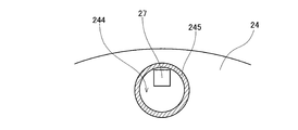
- FIG. 5 is a diagram conceptually showing the shape of the conductive plate 24 and the terminal pin 27 in a top view.
- the conduction plate 24 of the present embodiment has a through hole 244 positioned above the recess 224.
- a land (first land) 245 from which the copper foil is exposed is provided on the inner periphery of the conductive plate 24 that forms the through hole 244.
- the terminal pin 27 extends in the axial direction through the inside of the through hole 244.
- the conductive wire 70 is wound up to a position above the through hole 244. That is, the upper end of the third conducting wire portion 73 is located above the through hole 244.
- the terminal pin 27 contacts the land 245 directly or via the solder 74. Thereby, the terminal pin 27 and the land 245 of the conductive plate 24 are electrically connected.
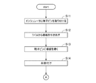
- FIG. 6 is a flowchart showing a procedure before injection molding of the casing 22.
- the terminal pin 27 is attached to the upper surface of the base portion 54 of the insulator 212 (step S11).
- press fitting or adhesion may be used for fixing the base portion 54 and the terminal pin 27.
- the base portion 54 and the terminal pin 27 may be fixed to each other by molding the base portion 54 using the terminal pin 27 as an insert part.
- the conducting wire 70 constituting the coil 213 is passed through the slit 55, and the end of the conducting wire 70 is pulled out to the terminal pin 27 side (step S12).
- the first conducting wire portion 71 of the conducting wire 70 is disposed along the slit 55 of the insulator 212. That is, a part of the path of the conducting wire 70 from the coil 213 toward the terminal pin 27 is positioned by the slit 55. Thereby, it can prevent that the conducting wire 70 contacts with another member. As a result, the conductor 70 is prevented from being damaged or broken.
- the drawn lead wire 70 is wound around the terminal pin 27 (step S13).
- the conducting wire 70 is wound upward from the vicinity of the lower end portion of the terminal pin 27 to the vicinity of the upper end portion thereof. At this time, the conducting wire 70 is wound around the terminal pin 27 with a gap for each turn.
- the conducting wire 70 and the terminal pin 27 are subsequently soldered (step S14).
- the solder is interposed between the conductive wire 70 wound around the terminal pin 27 and the conductive wire 70.
- the conducting wire 70 and the terminal pin 27 can be favorably conducted.
- the drive current supplied from the external power source can be stably supplied to the stator 21, and the electrical reliability of the motor 1 can be improved.
- FIG. 7 is a flowchart showing a procedure at the time of injection molding of the casing 22.
- FIG. 8 is a view showing a state at the time of injection molding.
- a mold is prepared (step S21).
- the mold is composed of an upper mold 90 and a lower mold, which form a cavity inside when combined with each other.
- the structure containing the stator 21, the terminal pin 27, and the conducting wire 70 obtained by the procedure of FIG. 6 is arrange
- the lower surface of the upper mold 90 is in contact with the upper surface of the base portion 54 of the insulator 212. Then, the terminal pin 27 is enclosed by the upper mold 90.
- a mold recess 91 is provided on the lower surface of the upper mold 90.
- the mold recess 91 is recessed upward in the axial direction above the base portion 54.
- the insulator 212 has a protruding portion 56 that slightly protrudes from the upper surface of the base portion 54 toward the upper side.
- the protruding portion 56 extends in an arc shape around the terminal pin 27.
- the shape of the protruding portion 56 may be other shapes such as a rectangular shape with a part missing.
- the protruding portion 56 only needs to surround the terminal pin 27 except for a portion overlapping the slit 55.
- the insulator 212 of the present embodiment further includes a slit protrusion 57 adjacent to the upper portion of the slit 55 and connected to the protrusion 56.
- the lower surface of the upper mold 90 contacts not only the protrusion 56 described above but also the slit protrusion 57.
- the slit protrusion 57 is crushed by the upper mold 90 and falls to the slit 55 side. Thereby, the opening of the upper part of the slit 55 becomes narrow. As a result, in a subsequent process, the flowing resin is suppressed from flowing from the slit 55 to the terminal pin 27 side.
- the protrusion part 56 has the taper part 58 which inclines so that it may leave
- the slit protrusion part 57 also has the taper part 59 which inclines so that it may leave
- the taper part 59 is provided, when the slit protrusion part 57 is crushed, the slit protrusion part 57 easily falls down to the slit 55 side. Thereby, the inflow of the resin from the slit 55 to the terminal pin 27 side can be further suppressed.
- step S24 After closing the upper mold 90 and the lower mold (step S23), the resin in a fluid state is poured into the cavity in the mold (step S24). At this time, the resin in a fluid state is supplied to the outside of the mold recess 91 as indicated by the broken line arrow in FIG. 8, but the space between the upper mold 90 and the base portion 54 is closed as described above. Therefore, the resin in a fluid state is difficult to flow into the mold recess 91. Eventually, when the resin reaches the entire cavity in the mold, the resin in a fluid state is cured (step S25). Thereby, the casing 22 is obtained. A concave portion 224 is formed on the upper side of the base portion 54, and a part of the terminal pin 27 is disposed in the concave portion 224.
- step S26 the upper mold 90 and the lower mold are separated, and the mold is opened (step S26). And the structure containing the stator 21, the terminal pin 27, the conducting wire 70, and the casing 22 after molding is taken out from the mold (step S27).
- the extracted structure at least the lower end portion of the terminal pin 27 is disposed in the recess 224.
- the second conductor portion 72 wound around the lower portion of the terminal pin 27 is also located in the recess 224.
- the third conductor portion 73 wound around the upper portion of the terminal pin 27 is positioned above the recess 224.
- the conductive wire 70 wound around the terminal pin 27 can be prevented from coming into contact with the mold when the casing 22 is molded. For this reason, the winding space
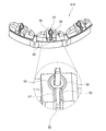
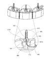
- FIG. 9 is a longitudinal sectional view of the motor 1C.
- FIG. 10 is an enlarged cross-sectional view of the motor 1C.
- the motor 1C is a so-called outer rotor type motor in which a magnet 35C is disposed on the radially outer side of the stator 21C.
- the motor 1C is used for home appliances such as a ceiling fan and an outdoor unit of an air conditioner, for example.
- the motor of the present invention may be used for applications other than home appliances.
- the motor 1C of the present invention may be mounted on transportation equipment such as automobiles and railways, OA equipment, medical equipment, tools, industrial large equipment, and the like to generate various driving forces.
- the motor 1C has a stationary part 2C and a rotating part 3C.
- the stationary part 2C is fixed to the frame of the device to be driven.
- the rotating part 3C is supported so as to be rotatable with respect to the stationary part 2C.
- the stationary part 2C of the present embodiment includes a stator 21C, a casing 22C, a cover 23C, a conduction plate 24C, a lower bearing part 25C, an upper bearing part 26C, and a terminal pin 27C.
- the rotating part 3C has a shaft 31C and a rotor 32C.
- the stator 21C is an armature that generates a magnetic flux in accordance with a drive current supplied from an external power source through the conduction plate 24C.
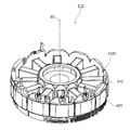
- FIG. 11 is a perspective view of the stator 21C. In FIG. 11, the conductor 70C and the solder 74C are not shown. As shown in FIGS. 9 to 11, the stator 21C surrounds the central axis 9C extending vertically in an annular shape.
- the stator 21C includes a stator core 211C, an insulator 212C, and a plurality of coils 213C.
- the stator core 211C has an annular core back 41C and a plurality of teeth 42C that protrude radially outward from the core back 41C.
- the core back 41C is disposed substantially coaxially with the central axis 9C.
- the plurality of teeth 42C are arranged at equal intervals in the circumferential direction. For example, a laminated steel plate is used for the stator core 211C.
- the insulator 212C is attached to the stator core 211C.
- a resin that is an insulator is used as the material of the insulator 212C.
- the insulator 212C covers at least both end surfaces in the axial direction and both surfaces in the circumferential direction of the teeth 42C.
- the coil 213C includes a conductive wire 70C wound around the teeth 42C via an insulator 212C. That is, the insulator 212C is interposed between the tooth 42C and the coil 213C.
- the casing 22C is a resin member that holds the stator 21C, the lower bearing portion 25C, and the upper bearing portion 26C.
- the casing 22C includes a wall portion 221C, a bottom plate portion 222C, an upper plate portion 231C, an upper bearing holding portion 232C, and a lower bearing holding portion 223C.
- the upper portion of the stator 21C is covered with a resin constituting the upper plate portion 231C.
- the upper plate portion 231C extends to the outside in the radial direction from the rotor 32C described later.
- the wall portion 221C extends in a substantially cylindrical shape upward in the axial direction from the radially outer end portion of the upper plate portion 231C.
- the lower part of the stator 21C is covered with a resin constituting the bottom plate part 222C.
- the lower bearing holding portion 223C extends from the radially inner side surface of the bottom plate portion 222C toward the shaft 31C and covers a part of the lower bearing portion 25C.
- the upper bearing holding portion 232C extends from the radially inner side surface of the upper plate portion 231C toward the shaft 31C and covers a part of the upper bearing portion 26C. Thereby, the lower bearing portion 25C and the upper bearing portion 26C are held.
- the upper bearing holding portion 232C and the lower bearing holding portion 223C may be the same member as the casing 22C or may be separate members.
- the cover 23C covers the upper opening of the casing 22C.
- the cover 23C extends substantially perpendicular to the central axis 9C on the axial upper side of the stator 21C, the casing 22C, the conduction plate 24C, and the rotor 32C.
- the cover 23 ⁇ / b> C has a fixing portion 233 ⁇ / b> C that protrudes in an annular shape downward in the axial direction.
- the fixing portion 233C contacts the inner peripheral portion of the wall portion 221C in the circumferential direction. Thereby, the cover 23C is fixed at the upper part of the casing 22C.
- the cover 23C and the casing 22C form a storage portion 28C above the stator 21C. That is, at least a part of the casing 22C is disposed between the storage portion 28C and the rotor 32C.
- the conductive plate 24C is a circuit board disposed substantially perpendicular to the central axis 9C.
- the conductive plate 24C is disposed inside the storage portion 28C.
- the conductive plate 24C is connected to an external power source via a lead wire (not shown). The current supplied from the external power source flows to the coil 213 through the lead wire, the conduction plate 24C, and a terminal pin 27C described later.
- the lower bearing portion 25C rotatably supports the shaft 31C below the rotor 32C.
- the upper bearing portion 26C rotatably supports the shaft 31C above the rotor 32C.
- ball bearings that rotate the outer ring and the inner ring via a sphere are used.
- the outer ring of the lower bearing portion 25C is fixed to the lower bearing holding portion 223C.
- the outer ring of the upper bearing portion 26C is fixed to the upper bearing holding portion 232C.
- the inner rings of the lower bearing portion 25C and the upper bearing portion 26C are fixed to the shaft 31C.
- other types of bearings such as a slide bearing and a fluid bearing may be used instead of the ball bearing.
- the upper bearing portion 26C is disposed above the core back 41C.
- the lower bearing portion 25C is disposed below the core back 41C. At least a part of the upper bearing portion 26C and the lower bearing portion 25C may overlap the core back 41C in the axial direction.
- the distal end portion on the radially outer side of the teeth 42C is located on the radially outer side with respect to the upper bearing portion 26C and the lower bearing portion 25C.
- the terminal pin 27C mentioned later is arrange
- the shaft 31C is a substantially cylindrical member that extends vertically along the central axis 9C.
- a metal such as stainless steel is used as the material of the shaft 31C.
- the shaft 31C rotates around the central axis 9C.
- the rotor 32C is an annular member that is fixed to the shaft 31C and rotates together with the shaft 31C. As shown in FIG. 1, the rotor 32C has a disk portion 33C, a cylindrical portion 34C, and a magnet 35C.
- the disc portion 33C is a plate-like portion that extends radially outward from the outer peripheral portion of the shaft 31C.
- the cylindrical portion 34C is a substantially cylindrical portion located on the radially outer side than the disc portion 33C.
- An impeller 4C is attached to the outer peripheral portion of the cylindrical portion 34C.
- the magnet 35C is a substantially annular magnetic body located on the radially outer side of the stator 21C.
- the magnet 35C is fixed to the inner peripheral surface of the cylindrical portion 34C via, for example, an adhesive.
- the magnet 35C may be fixed to the inner peripheral surface of the cylindrical portion 34C by other methods.
- the inner peripheral surface of the magnet 35C faces the radially outer end surfaces of the plurality of teeth 42C via a slight gap.
- N poles and S poles are alternately magnetized in the circumferential direction on the inner peripheral surface of the magnet 35C.
- a plurality of magnets may be used in place of the annular magnet 35C. When a plurality of magnets are used, the plurality of magnets may be arranged in the circumferential direction so that the N poles and the S poles are alternately arranged.
- a driving current is supplied from an external power source to the coil 213C through a lead wire (not shown), a conduction plate 24C, and a terminal pin 27C described later.
- magnetic flux is generated in the plurality of teeth 42 ⁇ / b> C of the stator core 211.
- a circumferential torque is generated by the action of the magnetic flux between the teeth 42C and the magnet 35C.
- the rotating unit 3C including the impeller 4C rotates around the central axis 9C.
- FIG. 12 is a perspective view showing a part of the terminal pin 27C and the insulator 212C.
- FIG. 13 is a partial cross-sectional view of the vicinity of the terminal pin 27C of the motor 1C. In FIG. 12, illustration of the solder 74C is omitted.
- the insulator 212C has a first insulating part 51C and a base part 54C.
- the first insulating portion 51C and the base portion 54C may be a single member or may be composed of a plurality of members.
- the first insulating portion 51C covers both end surfaces in the axial direction and both surfaces in the circumferential direction of the teeth 42C.
- a slit 55C that is recessed radially inward is provided on the radially outer side surface of the base portion 54C.
- the slit 55C extends in the axial direction from the upper end of the base portion 54C toward the lower side. Further, as shown in FIG.
- the insulator 212C of the present embodiment has a protruding portion 56C that slightly protrudes upward from the upper surface of the base portion 54C.
- the configuration of the protruding portion 56C is the same as that of the first embodiment, and thus the description thereof is omitted.
- a terminal pin 27C is provided on the base portion 54C.
- the terminal pin 27C is a columnar conductor that protrudes upward in the axial direction toward the storage portion 28C.
- the terminal pin 27C is formed of a conductive material such as iron or copper.
- the lower end portion of the terminal pin 27C is inserted into a hole provided in the base portion 54C and fixed to the base portion 54C.
- the upper end portion of the terminal pin 27C is located above the upper surface of the base portion 54C.
- one terminal pin 27C is fixed to one base portion 54C.
- two or more terminal pins 27C may be fixed to one base portion 54C.
- the base portion 54C is disposed above the distal end portion in the radial direction of the teeth 42C. That is, the terminal pin 27C is disposed above the tip of the tooth 42C. Thereby, an insulation distance can be ensured between the upper bearing portion 26C and the terminal pin 27C. Therefore, an electrical short circuit between the upper bearing portion 26C and the terminal pin 27C can be prevented. Further, by arranging the terminal pin 27C above the tip of the tooth 42C, it is possible to secure an insulation distance while suppressing the radial width of the core back 41C. Thereby, a motor can be reduced in size.
- the stator core 211C, the insulator 212C, and the coil 213C are at least partially covered by the casing 22C.
- the casing 22C has a recess 224C that is recessed in the axial direction above the base portion 54C of the insulator 212C.
- the upper surface of the base portion 54C is located in the recess 224C. Therefore, the upper surface of the base portion 54C is exposed from the casing 22C.
- at least the lower end portion of the terminal pin 27C is arranged in the recess 224C without contacting the casing 22C.
- the casing 22C is obtained by injection molding in which a resin is poured into a cavity in a mold in which the stator 21C and the terminal pins 27C are accommodated to be cured.
- the casing 22 ⁇ / b> C of the present embodiment has a conductive plate arrangement surface 225 ⁇ / b> C that contacts the lower surface of the conductive plate 24 ⁇ / b> C. Thereby, the downward displacement of the conduction plate 24C is prevented by the conduction plate arrangement surface 225C.
- the conducting wire 70C extends from the coil 213C located on the radially inner side of the base portion 54C and is drawn out to the slit 55C side.
- the conducting wire 70C has a first conducting wire portion 71C and a second conducting wire portion 72C.
- the first conductor portion 71C is located in the slit 55C.
- the second conductor portion 72C is connected to the first conductor portion 71C and is wound around the lower portion of the terminal pin 27C.
- the second conductor portion 72C is located in the recess 224C.
- the conducting wire 70C may further include a third conducting wire portion that is connected to the second conducting wire portion 72C and is wound around the upper portion of the terminal pin 27C.
- the conducting wire 70C extending from the coil 213C may pass up through the slit 55C and be wound up above the recess 224C from the lower part to the upper part of the terminal pin 27C.
- the winding interval of the conducting wire 70C wound around the terminal pin 27C can be widened, and the electrical reliability can be improved.
- the base portion 54C of the insulator 212C has a base protrusion 59C that protrudes outward in the radial direction.
- the slit 55C is formed from above to below the base protrusion 59C.
- the base protrusion 59C has a curved portion 591C that curves in the circumferential direction from the side surface facing the slit 55C to the bottom surface.
- the first conductor portion 71C is disposed along the curved portion 591C. Thereby, the conductor 70C can be wound around the terminal pin 27C while the conductor 70C is hooked on the base protrusion 59C. For this reason, it becomes easy to wire the conducting wire 70C from the winding portion to the slit 55C. Further, it is possible to prevent the conductor 70C from being damaged by coming into contact with the base protrusion 59C. Therefore, a thin wire with low tension, a lead wire made of aluminum alloy, or the like can be used as the lead wire 70C.
- the lead wire 70C and the die are not contacted without covering the lead wire 70C positioned between the base portion 54C and the die at the time of injection molding of the casing 22C. maintain. Therefore, the conductive wire 70C can be wound up to the vicinity of the upper end portion of the terminal pin 27C without being blocked by such a protective member.
- a gap 227C is interposed between the second conductor portion 72C and the solder 74C and the casing 22C in the recess 224C. That is, at the time of injection molding of the casing 22C, the mold does not come into contact with the terminal pins 27C, the conductive wires 70C, and the solder 74C. For this reason, it is possible to prevent the terminal pin 27C, the conductive wire 70C, and the solder 74C from being damaged.
- the conducting wire 70C is wound around the terminal pin 27C with a gap for each turn. Then, solder 74C is interposed in the gap between the conductive wire 70C wound around the terminal pin 27C and the conductive wire 70C.
- the conducting wire 70C and the terminal pin 27C can be conducted more favorably. As a result, the drive current supplied from the external power supply can be stably supplied to the stator 21C, and the electrical reliability of the motor 1C can be improved.
- FIG. 14 is a top view of the casing 22C.
- FIG. 15 is a partial cross-sectional view of the motor 1C.
- the casing 22C has a groove portion 226C that is recessed downward between the adjacent terminal pins 27C.
- the groove 226C overlaps at least a part of the magnet 35C in the axial direction.
- the position detection element 29C is arrange
- the position detection element 29C is, for example, a hall sensor, and detects the magnetic flux of the magnet.
- the position detection element 29C is disposed inside the groove 226C, and thus overlaps the magnet in the axial direction. Thereby, the position detection element 29C can detect the position and rotational speed of the rotor 32C.
- the rotational speed of the rotor 32C is feedback controlled based on the detection result of the position detection element 29C.
- the position detection element 29C may be attached to the conduction plate 24C, or may be a separate member from the conduction plate 24C.
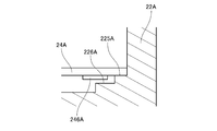
- FIG. 16 is a partial vertical cross-sectional view of the motor according to a modified example near the end of the conductive plate 24A.
- the casing 22A has a conductive plate arrangement surface 225A and a step surface 226A.
- the step surface 226A is located on the radially inner side and the axially lower side of the conductive plate arrangement surface 225A.
- a gap in the axial direction is interposed between the lower surface of the conductive plate 24A and the step surface 226A.
- the electronic component 246A can be disposed on the lower surface of the conductive plate 24A at a position above the step surface 226A.
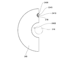
- FIG. 17 is a top view of a conduction plate 24B according to another modification.
- the conduction plate 24B has a first notch 247B located above the recess 224B.
- a land (second land) 245B from which the copper foil is exposed is provided at the inner edge of the first notch 247B.
- the terminal pin 27B extends in the axial direction through the inside of the first notch 247B.
- the conducting wire is wound up to a position above the first notch 247B. That is, the upper end of the third conductor portion is located above the first notch 247B.
- the terminal pin 27B contacts the land directly or via solder. Thereby, the terminal pin 27B and the conducting plate 24B are conducted.
- the conduction plate 24B of FIG. 17 further includes a second notch 248B that opens inward in the radial direction. At least a portion of the shaft 31B is disposed in the second notch 248B.
- the direction of the opening of the first notch 247B and the direction of the opening of the second notch 248B are the same direction.
- the conduction plate 24B can be inserted obliquely or laterally with respect to the axial direction. Therefore, after arranging the rotating part to which the lower bearing and the upper bearing are attached inside the casing after the injection molding, the conducting plate 24B is arranged at a position closer to the rotor than the upper bearing, and the conducting plate 24B and the terminal pin 27B Can be soldered. Thereby, the freedom degree of the operation
- FIG. 18 is a longitudinal sectional view of the vicinity of a terminal pin 27D of a motor 1D according to another modification.
- FIG. 19 is a partial perspective view of the base portion 54D, the casing 22D, and the terminal pins 27D of the motor 1D.
- the recess 224D of the casing 22D includes a first recess 81D, a second recess 82D, a pair of third recesses 83D, and a fourth recess 84D.
- the first recess 81D, the second recess 82D, the third recess 83D, and the fourth recess 84D are connected to each other.
- 1st recessed part 81D is located above the base part 54D of insulator 212D.
- the upper surface of the base portion 54D is exposed in the first recess 81D.
- At least a portion of the terminal pin 27D is located in the first recess 81D.
- substantially the entire upper surface of the base portion 54D is exposed in the first recess 81D.
- a part of the upper surface of the base portion 54D may be covered with a resin constituting the casing 22D.
- 2nd recessed part 82D is located in the radial direction outer side of the base part 54D.
- the side surface having the slit 55D of the base portion 54D is exposed in the second recess 82D.
- the lower end portion of the second recess 82D is positioned above the upper surface of the second insulating portion 52D of the insulator 212D. For this reason, only a part including the upper end portion of the side surface having the slit 55D of the base portion 54D is exposed in the second recess 82D.
- the lower end portion of the second recessed portion 82D may be the same height as the upper surface of the second insulating portion 52D.
- the whole side surface which has the slit 55D of the base part 54D, and a part of upper surface of 2nd insulating part 52D may be exposed in 2nd recessed part 82D.
- the pair of third recesses 83D are located on both sides of the base portion 54 in the circumferential direction. Both side surfaces of the base portion 54D in the circumferential direction are exposed in the third recess 83D.
- the lower end portion of the third recess 83D is positioned above the upper surface of the second insulating portion 52D of the insulator 212D. For this reason, only a part including the upper end portion of the side surface in the circumferential direction of the base portion 54D is exposed in the third recess 83D.
- the lower end portion of the third recess portion 83D may be the same height as the upper surface of the second insulating portion 52D.
- the entire circumferential side surface of the base portion 54D and a part of the upper surface of the second insulating portion 52D may be exposed in the third recess 83D.
- the radially inner end of the third recess 83D is located more radially outward than the radially inner side surface of the base portion 54D. For this reason, only a part of the outer side in the radial direction of the side surface in the circumferential direction of the base portion 54D is exposed in the third recess 83D.
- the third recess 83D may extend to a radial position equivalent to the radially inner side surface of the base portion 54D.
- the coil 213D should not be exposed in the third recess 83D.
- the fourth recess 84D is located on the radially inner side of the terminal pin 27D and above the coil 213D.
- the lower end of the fourth recess 84D is positioned above the lower end in the axial direction of the second recess 82D and the third recess 83D.
- the fourth recess 84D does not reach the coil 213D.
- the height of the lower end portion of the fourth recess 84 ⁇ / b> D is the same as the upper surface of the base portion 54 ⁇ / b> D.
- the height of the lower end portion of the fourth recess 84D may be a height different from the upper surface of the base portion 54D.
- FIG. 20 is a cross-sectional view showing a state when the casing 22D is injection-molded in the manufacturing process of the motor 1D.
- an upper mold 90D and a lower mold 92D corresponding to the shape of the casing 22D are prepared. Then, a structure including the stator 21D, the terminal pins 27D, and the conductive wire 70D is disposed between the upper mold 90D and the lower mold 92D.
- the lower surface of the upper mold 90D is in contact with the upper surface of the base portion 54D.
- the terminal pin 27D is enclosed by the upper mold 90D.
- the terminal pin 27D is accommodated in a mold recess 91D provided in the upper mold 90D.
- die 90D and conducting wire 70D are maintained in non-contact.
- the upper mold 90D also contacts the side surface having the slit 55D of the base portion 54D and both side surfaces in the circumferential direction. Thereby, the space in the mold recess 91D is further isolated from the surroundings.
- the upper mold 90D contacts not only the upper surface of the base portion 54D but also the side surface of the base portion 54D having the slits 55D. Thereby, it can suppress that resin flows into the metal mold
- the upper mold 90D also contacts the circumferential side surface of the base portion 54D. Thereby, it can suppress more that resin flows into metallic mold crevice 91D. As a result, it is possible to further suppress the resin from entering the periphery of the terminal pin 27D.
- a part of the upper mold 90D is also arranged at the radially inner side of the terminal pin 27D and above the coil 213D, that is, at the position where the fourth recess 84D is formed after molding. Thereby, it can suppress that resin penetrate
- the shaft protrudes upward from the casing and the cover.
- the shaft may protrude downward from the casing, and the lower end portion thereof may be connected to the drive unit.
- the shaft may protrude both below the casing and above the cover, and both the lower end portion and the upper end portion thereof may be coupled to the drive unit.
- a rotor made of magnet resin is used.
- the rotor may be one in which a plurality of magnets are fixed to the outer peripheral surface or inside of a cylindrical rotor core that is a magnetic body.
- the conductive plate of the above embodiment is a circuit board on which an electronic circuit for supplying a drive current to the coil is mounted.
- the conductive plate may be a wiring board that supports the lead wires.
- the lead wire may be disposed along the surface of the wiring board, and the lead wire and the terminal pin may be directly connected.
- the terminal pins and the conductive wires are electrically connected by soldering.
- the means for electrically connecting the terminal pins and the conductive wires may be other methods such as heat caulking, conductive adhesive, welding, and the like.
- the cross-sectional shape perpendicular to the central axis of the metal terminal is rectangular.
- the cross-sectional shape of the metal terminal may be other shapes such as a circle.
- each member may be different from the shape shown in each drawing of the present application. Moreover, you may combine suitably each element which appeared in said embodiment and modification in the range which does not produce inconsistency.
- the present invention can be used for a motor and a method for manufacturing the motor.
Landscapes
- Engineering & Computer Science (AREA)
- Power Engineering (AREA)
- Manufacturing & Machinery (AREA)
- Insulation, Fastening Of Motor, Generator Windings (AREA)
- Motor Or Generator Frames (AREA)
- Manufacture Of Motors, Generators (AREA)
Abstract
Description
<1-1.モータの構造>
図1は、モータ1の縦断面図である。このモータ1は、ステータ21の径方向内側にロータ32が配置された、いわゆるインナーロータ型のモータである。モータ1は、例えば、空調機等の家電製品に使用される。ただし、本発明のモータ1は、家電製品以外の用途に使用されるものであってもよい。例えば、本発明のモータ1は、自動車や鉄道等の輸送機器、OA機器、医療機器、工具、産業用の大型設備等に搭載されて、種々の駆動力を発生させるものであってもよい。
次に、モータ1の端子ピン27付近の構造について、より詳細に説明する。図2は、モータ1の端子ピン27付近の部分断面図である。図3は端子ピン27およびインシュレータ212の一部分を示す斜視図である。なお、図3では、導線70および半田74の図示が省略されている。
続いて、ケーシング22の射出成型について説明する。
<2-1.モータの構造>
次に、第2実施形態に係るモータの構成について説明する。なお、ケーシングの射出成型の方法および導通板の構成については、第1実施形態に係るモータ1と同様であるため、説明を省略する。図9は、モータ1Cの縦断面図である。図10は、モータ1Cの拡大断面図である。このモータ1Cは、ステータ21Cの径方向外側にマグネット35Cが配置される、いわゆるアウターロータ型のモータである。モータ1Cは、例えば、シーリングファンや、エアコンディショナーの室外機等の家電製品に使用される。ただし、本発明のモータは、家電製品以外の用途に使用されるものであってもよい。例えば、本発明のモータ1Cは、自動車や鉄道等の輸送機器、OA機器、医療機器、工具、産業用の大型設備等に搭載されて、種々の駆動力を発生させるものであってもよい。
次に、モータ1Cの端子ピン27C付近の構造について、より詳細に説明する。図12は端子ピン27Cおよびインシュレータ212Cの一部分を示す斜視図である。図13は、モータ1Cの端子ピン27C付近の部分断面図である。なお、図12では、半田74Cの図示が省略されている。
以上、本発明の例示的な実施形態について説明したが、本発明は上記の実施形態には限定されない。
2 静止部
3 回転部
9 中心軸
21 ステータ
22 ケーシング
23 カバー
24 導通板
25 下軸受部
26 上軸受部
27 端子ピン
29C 位置検出素子
31 シャフト
32 ロータ
35C マグネット
41 コアバック
42 ティース
51 第1絶縁部
52 第2絶縁部
53 第3絶縁部
54 土台部
55 スリット
56 突出部
57 スリット突出部
58 テーパ部
59C 土台突出部
70 導線
71 第1導線部
72 第2導線部
73 第3導線部
74 半田
90 上金型
91 金型凹部
201 接続孔
211 ステータコア
212 インシュレータ
213 コイル
221 壁部
222 底板部
223 下軸受保持部
224 凹部
225 導通板配置面
226C 溝部226C
227 空隙
231 上板部
232 上軸受保持部
242 リード線
243 ブッシング
244 貫通孔
245 ランド
311 溝
321 内側筒部
322 外側筒部
323 連結部
591C 湾曲部
Claims (28)
- ステータを含む静止部と、
前記静止部と径方向に対向し、上下に延びる中心軸を中心に回転するロータを含む回転部と、
を有し、
前記静止部は、
環状のコアバックおよび前記コアバックから径方向へ突出する複数のティースを有するステータコアと、
前記ステータコアの少なくとも一部を覆うインシュレータと、
前記インシュレータを介して前記ティースに巻かれた導線からなるコイルと、
前記インシュレータの土台部から上方へ延びる端子ピンと、
前記ステータの上方に配置される導通板と、
前記ステータコア、前記インシュレータ、および前記コイルを覆う樹脂製のケーシングと、
を有し、
前記ケーシングは、軸方向に凹む凹部を有し、
前記端子ピンの少なくとも一部分が、前記凹部内に位置し、
前記導線は、
前記土台部に設けられたスリット内に位置する第1導線部と、
前記第1導線部と繋がり、前記端子ピンの下部に巻かれる第2導線部と、
を有する、モータ。 - 請求項1に記載のモータであって、
前記導線は、前記端子ピンに、一巻きごとに間隙をあけて巻かれ、
前記間隙に半田が介在する、モータ。 - 請求項2に記載のモータであって、
前記凹部内で、前記第2導線部および前記半田と、前記ケーシングとの間に、空隙が介在する、モータ。 - 請求項1から請求項3までのいずれか1項に記載のモータであって、
前記導線は、前記第2導線部と繋がり、前記端子ピンの上部に巻かれる第3導線部をさらに有し、
前記第3導線部は、前記凹部よりも上方に位置する、モータ。 - 請求項1から請求項4までのいずれか1項に記載のモータであって、
前記凹部は、第1凹部を有し、
前記土台部の上面は、前記第1凹部内で露出する、モータ。 - 請求項5に記載のモータであって、
前記凹部は、第2凹部をさらに有し、
前記土台部の前記スリットを有する側面は、前記第2凹部内で露出する、モータ。 - 請求項5または請求項6に記載のモータであって、
前記凹部は、第3凹部をさらに有し、
前記土台部の周方向の側面は、前記第3凹部内で露出する、モータ。 - 請求項6に記載のモータであって、
前記凹部は、第4凹部をさらに有し、
前記第4凹部は、前記コイルの上方に位置し、
前記第4凹部の下端部は、前記第2凹部の下端部よりも上側に位置する、モータ。 - 請求項1から請求項8までのいずれか1項に記載のモータであって、
前記土台部の上面は、前記端子ピンの周囲に位置する突出部を備える、モータ。 - 請求項1から請求項9までのいずれか1項に記載のモータであって、
前記土台部は、径方向外側に向けて突出する土台突出部をさらに有し、
前記スリットは、前記土台突出部の上方から下方にかけて形成される、モータ。 - 請求項10に記載のモータであって、
前記土台突出部は、前記スリットに面する側面から下面にかけて、周方向に湾曲する湾曲部を有し、
前記第1導線部は、前記湾曲部に沿って配置される、モータ。 - 請求項1から請求項11までのいずれか1項に記載のモータであって、
前記導線の材料は、アルミニウム合金である、モータ。 - 請求項1から請求項12までのいずれか1項に記載のモータであって、
前記ケーシングは、前記導通板の下面に接触する導通板配置面を有し、
前記導通板配置面は、前記ロータの少なくとも外周部の上端部よりも軸方向上側に位置する、モータ。 - 請求項13に記載のモータであって、
前記ケーシングは、前記導通板配置面の径方向内側に、前記導通板配置面よりも軸方向下側に位置する段差面を有し、
前記導通板の下面と、前記段差面との間に、軸方向の隙間が介在する、モータ。 - 請求項4に記載のモータであって、
前記導通板は、前記凹部の上方に位置し、その内周部に第1ランドを備える貫通孔を有し、
前記端子ピンは、前記貫通孔の内部に配置されるとともに、前記第1ランドと直接または半田を介して接触し、
前記第3導線部の上端は、前記貫通孔よりも上側に位置する、モータ。 - 請求項4に記載のモータであって、
前記導通板は、前記凹部の上方に位置し、その内側の端縁に第2ランドを備える第1切り欠きを有し、
前記端子ピンは、前記第1切り欠きの内部に配置されるとともに、前記第2ランドと直接または半田を介して接触し、
前記第3導線部の上端は、前記第1切り欠きよりも上側に位置する、モータ。 - 請求項16に記載のモータであって、
前記回転部は、
前記ロータを貫いて軸方向に延びるシャフト
をさらに有し、
前記導通板は、径方向内側へ向けて開いた第2切り欠きを有し、
前記シャフトの少なくとも一部分が、前記第2切り欠き内に配置され、
前記第1切り欠きの開口の向きと、前記第2切り欠きの開口の向きとが、同方向である、モータ。 - 請求項1から請求項17までのいずれか1項に記載のモータであって、
前記中心軸に対して垂直な断面における前記端子ピンの形状が矩形である、モータ。 - 請求項1から請求項18までのいずれか1項に記載のモータであって、
前記ロータは、前記ステータの径方向外側に配置されたマグネットを有し、
前記複数のティースは、前記コアバックから径方向外側へ突出する、モータ。 - 請求項19に記載のモータであって、
前記静止部と前記回転部とを回転可能に接続する軸受をさらに有し、
前記軸受は、前記コアバックの上方に配置され、
前記ティースの径方向外側の先端部は、前記軸受よりも径方向外側に位置し、
前記端子ピンは、前記ティースの前記先端部の上方に配置される、モータ。 - 請求項19または請求項20に記載のモータであって、
前記ケーシングは、前記ステータの上方に、収納部を形成し、
前記導通板は、前記収納部の内部に配置され、
前記端子ピンは、前記収納部に向けて上方に突出し、
前記ケーシングの少なくとも一部は、前記収納部と、前記ロータとの間に配置される、モータ。 - 請求項19から請求項21までのいずれか1項に記載のモータであって、
前記ケーシングは、隣接する前記端子ピンの間に、溝部を有し、
前記溝部は、前記マグネットの少なくとも一部と軸方向に重なり、
前記溝部の内部には、前記ロータの位置を検出する位置検出素子が配置される、モータ。 - 請求項1から請求項18までのいずれか1項に記載のモータであって、
前記回転部は、前記ステータの径方向内側に配置され、
前記複数のティースは、前記コアバックから径方向内側へ突出する、モータ。 - ステータコアとコイルとの間にインシュレータが介在し、前記ステータコア、前記コイル、および前記インシュレータを覆う樹脂製のケーシングを有するモータの製造方法であって、
a)前記インシュレータの土台部の上面に、端子ピンを取り付ける工程と、
b)前記コイルを構成する導線の端部を、前記端子ピンへ引き出す工程と、
c)前記端子ピンに、前記導線を巻く工程と、
d)前記導線と前記端子ピンとを、半田付けする工程と、
e)互いに組み合わせることで内部に空洞が生じる上金型および下金型を用意する工程と、
f)前記上金型を前記土台部の上面に接触させ、前記上金型により前記端子ピンを囲いこむ工程と、
g)前記上金型と前記下金型とを組み合わせ、前記空洞内に前記ステータ、前記コイル、および前記インシュレータを収容する工程と、
h)前記空洞内に流動状態の樹脂を流し込む工程と、
i)前記流動状態の樹脂を硬化させて前記ケーシングを得る工程と、
j)前記上金型と前記下金型とを分離する工程と、
k)前記下金型から、前記ステータおよび前記ケーシングを取り出す工程と、
を有する、製造方法。 - 請求項24に記載の製造方法であって、
前記土台部の上面は、前記端子ピンの周囲に位置する突出部を備え、
前記工程e)では、前記上金型が前記突出部を押しつぶす、製造方法。 - 請求項25に記載の製造方法であって、
前記工程b)では、前記導線が、前記土台部の径方向外側に設けられたスリットを通って、前記端子ピンへ引き出され、
前記インシュレータは、前記スリットの上部に隣接し、前記突出部と繋がるスリット突出部をさらに有し、
前記工程e)では、前記上金型が前記スリット突出部を押しつぶす、製造方法。 - 請求項24から請求項26までのいずれか1項に記載の製造方法であって、
前記工程k)の後に、
l)導通板と前記端子ピンとを半田付けする工程
をさらに有し、
前記導通板は、内側の端縁にランドを備える第1切り欠きを有し、
前記工程l)では、前記第1切り欠きの内部に前記端子ピンを配置するとともに、前記端子ピンと前記ランドとを、直接または半田を介して接触させる、製造方法。 - 請求項27に記載の製造方法であって、
前記モータは、
前記ケーシングに対して回転可能に支持されるシャフトと、
前記シャフトに取り付けられた環状のロータと、
を有し、
前記工程l)では、前記ケーシングと前記シャフトとを接続する軸受よりも前記ロータ側の位置に、前記導通板を配置する、製造方法。
Priority Applications (3)
| Application Number | Priority Date | Filing Date | Title |
|---|---|---|---|
| CN201680039969.7A CN107852060A (zh) | 2015-07-29 | 2016-06-08 | 马达以及马达的制造方法 |
| JP2017531068A JPWO2017018066A1 (ja) | 2015-07-29 | 2016-06-08 | モータおよびモータの製造方法 |
| US15/743,702 US20180205281A1 (en) | 2015-07-29 | 2016-06-08 | Motor |
Applications Claiming Priority (4)
| Application Number | Priority Date | Filing Date | Title |
|---|---|---|---|
| JP2015-149493 | 2015-07-29 | ||
| JP2015149493 | 2015-07-29 | ||
| JP2016023259 | 2016-02-10 | ||
| JP2016-023259 | 2016-02-10 |
Publications (1)
| Publication Number | Publication Date |
|---|---|
| WO2017018066A1 true WO2017018066A1 (ja) | 2017-02-02 |
Family
ID=57885095
Family Applications (1)
| Application Number | Title | Priority Date | Filing Date |
|---|---|---|---|
| PCT/JP2016/067011 WO2017018066A1 (ja) | 2015-07-29 | 2016-06-08 | モータおよびモータの製造方法 |
Country Status (4)
| Country | Link |
|---|---|
| US (1) | US20180205281A1 (ja) |
| JP (1) | JPWO2017018066A1 (ja) |
| CN (1) | CN107852060A (ja) |
| WO (1) | WO2017018066A1 (ja) |
Cited By (3)
| Publication number | Priority date | Publication date | Assignee | Title |
|---|---|---|---|---|
| WO2018168090A1 (ja) * | 2017-03-14 | 2018-09-20 | 日本電産株式会社 | ステータ、モータ、電動パワーステアリング装置 |
| JP2019135692A (ja) * | 2018-02-05 | 2019-08-15 | 東芝ライテック株式会社 | 車両用照明装置、車両用灯具、およびソケットの製造方法 |
| JP2020054195A (ja) * | 2018-09-28 | 2020-04-02 | 日本電産サーボ株式会社 | モータ装置 |
Families Citing this family (3)
| Publication number | Priority date | Publication date | Assignee | Title |
|---|---|---|---|---|
| JP2019180200A (ja) * | 2018-03-30 | 2019-10-17 | 日本電産株式会社 | モータ及び送風装置 |
| JP2020102959A (ja) * | 2018-12-21 | 2020-07-02 | 株式会社マキタ | 電動作業機及び電動作業機用モータにおけるステータへのコイルの形成方法 |
| CN112531948A (zh) * | 2019-09-18 | 2021-03-19 | 泰科电子(上海)有限公司 | 线圈骨架和定子骨架 |
Citations (3)
| Publication number | Priority date | Publication date | Assignee | Title |
|---|---|---|---|---|
| JP2008172932A (ja) * | 2007-01-11 | 2008-07-24 | Nippon Densan Corp | レゾルバおよびレゾルバの製造方法 |
| WO2013171961A1 (ja) * | 2012-05-16 | 2013-11-21 | コベルコ建機株式会社 | 電動機アセンブリ及びその製造方法 |
| JP3192975U (ja) * | 2014-06-27 | 2014-09-11 | ミネベア株式会社 | アウターロータ型ブラシレスモータ |
Family Cites Families (2)
| Publication number | Priority date | Publication date | Assignee | Title |
|---|---|---|---|---|
| JP6057050B2 (ja) * | 2012-03-23 | 2017-01-11 | 株式会社富士通ゼネラル | モールドモータ |
| JP6175708B2 (ja) * | 2013-02-18 | 2017-08-09 | 日本電産テクノモータ株式会社 | モータ |
-
2016
- 2016-06-08 JP JP2017531068A patent/JPWO2017018066A1/ja active Pending
- 2016-06-08 WO PCT/JP2016/067011 patent/WO2017018066A1/ja active Application Filing
- 2016-06-08 CN CN201680039969.7A patent/CN107852060A/zh active Pending
- 2016-06-08 US US15/743,702 patent/US20180205281A1/en not_active Abandoned
Patent Citations (3)
| Publication number | Priority date | Publication date | Assignee | Title |
|---|---|---|---|---|
| JP2008172932A (ja) * | 2007-01-11 | 2008-07-24 | Nippon Densan Corp | レゾルバおよびレゾルバの製造方法 |
| WO2013171961A1 (ja) * | 2012-05-16 | 2013-11-21 | コベルコ建機株式会社 | 電動機アセンブリ及びその製造方法 |
| JP3192975U (ja) * | 2014-06-27 | 2014-09-11 | ミネベア株式会社 | アウターロータ型ブラシレスモータ |
Cited By (9)
| Publication number | Priority date | Publication date | Assignee | Title |
|---|---|---|---|---|
| WO2018168090A1 (ja) * | 2017-03-14 | 2018-09-20 | 日本電産株式会社 | ステータ、モータ、電動パワーステアリング装置 |
| CN109964389A (zh) * | 2017-03-14 | 2019-07-02 | 日本电产株式会社 | 定子、马达、电动助力转向装置 |
| JPWO2018168090A1 (ja) * | 2017-03-14 | 2020-01-16 | 日本電産株式会社 | ステータ、モータ、電動パワーステアリング装置 |
| CN109964389B (zh) * | 2017-03-14 | 2021-08-20 | 日本电产株式会社 | 定子、马达、电动助力转向装置 |
| JP7060007B2 (ja) | 2017-03-14 | 2022-04-26 | 日本電産株式会社 | ステータ、モータ、電動パワーステアリング装置 |
| JP2019135692A (ja) * | 2018-02-05 | 2019-08-15 | 東芝ライテック株式会社 | 車両用照明装置、車両用灯具、およびソケットの製造方法 |
| JP2020054195A (ja) * | 2018-09-28 | 2020-04-02 | 日本電産サーボ株式会社 | モータ装置 |
| WO2020067216A1 (ja) * | 2018-09-28 | 2020-04-02 | 日本電産サーボ株式会社 | モータ装置 |
| JP7336182B2 (ja) | 2018-09-28 | 2023-08-31 | ニデックアドバンスドモータ株式会社 | モータ装置 |
Also Published As
| Publication number | Publication date |
|---|---|
| JPWO2017018066A1 (ja) | 2018-05-31 |
| CN107852060A (zh) | 2018-03-27 |
| US20180205281A1 (en) | 2018-07-19 |
Similar Documents
| Publication | Publication Date | Title |
|---|---|---|
| WO2017018066A1 (ja) | モータおよびモータの製造方法 | |
| JP6175708B2 (ja) | モータ | |
| JP4662200B2 (ja) | モータおよびブスバー | |
| US9692270B2 (en) | Motor including brackets and fixing members | |
| US8922083B2 (en) | Rotor | |
| US20160365779A1 (en) | Rotor, motor and method of manufacturing the rotor | |
| JP5842365B2 (ja) | ロータユニット、回転電機、およびロータユニットの製造方法 | |
| JP6243208B2 (ja) | モータおよびモータの製造方法 | |
| JP6651545B2 (ja) | モータ | |
| JP2013066314A (ja) | モータおよびモータの製造方法 | |
| CN107846099B (zh) | 定子及制造定子的方法 | |
| JP4697597B2 (ja) | ブスバーおよびモータ | |
| JP6381347B2 (ja) | モータ | |
| JP6766535B2 (ja) | ステータユニット、モータ、およびファンモータ | |
| JP6184599B2 (ja) | 電動機の回転子、電動機、空気調和機、および電動機の回転子の製造方法 | |
| JP2017175897A (ja) | モータ | |
| JP2018207582A (ja) | 静止部、モータ、およびモータの製造方法 | |
| JP2019097371A (ja) | 静止部、モータ、およびモータの静止部の製造方法 | |
| JPWO2020067255A1 (ja) | モータ | |
| JP6229331B2 (ja) | モータ | |
| JP2019140871A (ja) | レゾルバのステータ構造およびレゾルバ | |
| JP2018143048A (ja) | 樹脂ケーシングの成型方法およびモータ | |
| JP2018143049A (ja) | モータの製造方法およびモータ | |
| JP6402231B2 (ja) | モータおよびモータの製造方法 | |
| JP2018207581A (ja) | 静止部およびモータ |
Legal Events
| Date | Code | Title | Description |
|---|---|---|---|
| 121 | Ep: the epo has been informed by wipo that ep was designated in this application |
Ref document number: 16830171 Country of ref document: EP Kind code of ref document: A1 |
|
| WWE | Wipo information: entry into national phase |
Ref document number: 15743702 Country of ref document: US |
|
| ENP | Entry into the national phase |
Ref document number: 2017531068 Country of ref document: JP Kind code of ref document: A |
|
| NENP | Non-entry into the national phase |
Ref country code: DE |
|
| 122 | Ep: pct application non-entry in european phase |
Ref document number: 16830171 Country of ref document: EP Kind code of ref document: A1 |