WO2019138471A1 - Support de brosse de polissage et dispositif de polissage - Google Patents
Support de brosse de polissage et dispositif de polissage Download PDFInfo
- Publication number
- WO2019138471A1 WO2019138471A1 PCT/JP2018/000340 JP2018000340W WO2019138471A1 WO 2019138471 A1 WO2019138471 A1 WO 2019138471A1 JP 2018000340 W JP2018000340 W JP 2018000340W WO 2019138471 A1 WO2019138471 A1 WO 2019138471A1
- Authority
- WO
- WIPO (PCT)
- Prior art keywords
- polishing brush
- polishing
- workpiece
- sleeve
- axial direction
- Prior art date
Links
Images


Classifications
-
- B—PERFORMING OPERATIONS; TRANSPORTING
- B24—GRINDING; POLISHING
- B24B—MACHINES, DEVICES, OR PROCESSES FOR GRINDING OR POLISHING; DRESSING OR CONDITIONING OF ABRADING SURFACES; FEEDING OF GRINDING, POLISHING, OR LAPPING AGENTS
- B24B29/00—Machines or devices for polishing surfaces on work by means of tools made of soft or flexible material with or without the application of solid or liquid polishing agents
- B24B29/005—Machines or devices for polishing surfaces on work by means of tools made of soft or flexible material with or without the application of solid or liquid polishing agents using brushes
-
- B—PERFORMING OPERATIONS; TRANSPORTING
- B24—GRINDING; POLISHING
- B24B—MACHINES, DEVICES, OR PROCESSES FOR GRINDING OR POLISHING; DRESSING OR CONDITIONING OF ABRADING SURFACES; FEEDING OF GRINDING, POLISHING, OR LAPPING AGENTS
- B24B29/00—Machines or devices for polishing surfaces on work by means of tools made of soft or flexible material with or without the application of solid or liquid polishing agents
-
- B—PERFORMING OPERATIONS; TRANSPORTING
- B24—GRINDING; POLISHING
- B24B—MACHINES, DEVICES, OR PROCESSES FOR GRINDING OR POLISHING; DRESSING OR CONDITIONING OF ABRADING SURFACES; FEEDING OF GRINDING, POLISHING, OR LAPPING AGENTS
- B24B49/00—Measuring or gauging equipment for controlling the feed movement of the grinding tool or work; Arrangements of indicating or measuring equipment, e.g. for indicating the start of the grinding operation
- B24B49/16—Measuring or gauging equipment for controlling the feed movement of the grinding tool or work; Arrangements of indicating or measuring equipment, e.g. for indicating the start of the grinding operation taking regard of the load
-
- B—PERFORMING OPERATIONS; TRANSPORTING
- B24—GRINDING; POLISHING
- B24D—TOOLS FOR GRINDING, BUFFING OR SHARPENING
- B24D13/00—Wheels having flexibly-acting working parts, e.g. buffing wheels; Mountings therefor
- B24D13/14—Wheels having flexibly-acting working parts, e.g. buffing wheels; Mountings therefor acting by the front face
-
- B—PERFORMING OPERATIONS; TRANSPORTING
- B24—GRINDING; POLISHING
- B24D—TOOLS FOR GRINDING, BUFFING OR SHARPENING
- B24D13/00—Wheels having flexibly-acting working parts, e.g. buffing wheels; Mountings therefor
- B24D13/20—Mountings for the wheels
Definitions
- the present invention relates to an abrasive brush holder for detachably holding an abrasive brush provided with a plurality of linear abrasives.
- the present invention also relates to an abrasive tool including an abrasive brush and an abrasive brush holder.
- Patent Document 1 describes an abrasive tool for cutting or polishing a workpiece.
- the polishing tool of the same document has a polishing brush and a polishing brush holder that detachably holds the polishing brush.
- the polishing brush has a plurality of linear abrasives arranged in parallel, and a holder for holding one end of the plurality of linear abrasives.
- the abrasive brush holder comprises a shank and a sleeve coaxial with the shank.
- the holder In the polishing brush, the holder is fixed in the sleeve, and the free ends (the other ends) of the plurality of linear abrasives are held by the polishing brush holder in a posture in which the free end protrudes from the sleeve.
- the shank of the polishing tool When cutting or polishing a workpiece, the shank of the polishing tool is connected to the spindle of the machine tool. The machine tool rotates the polishing tool about the axis of the shank and brings the other end of the plurality of linear abrasives protruding from the sleeve into contact with the workpiece.
- the machine tool moves the polishing tool in a direction approaching the workpiece as the linear abrasive wears, and the position of the free end of the linear abrasive relative to the workpiece It is conceivable to carry out the processing operation while maintaining the However, in the case where the machine tool performs such control, a control program for controlling the machine tool becomes complicated.
- an abrasive brush which has a holder which holds a plurality of linear abrasives arranged in parallel, and one end of the linear abrasives.
- An abrasive brush holder for holding includes a shank connected to a machine tool and a sleeve coaxial with the shank, the abrasive brush being positioned in the sleeve with the holder, the other of the plurality of linear abrasives
- a support mechanism for supporting the end of the sleeve so as to be movable in the axial direction of the shank in a posture where the end projects from the sleeve, a drive source, a movement mechanism for moving the polishing brush in the axial direction, and a support mechanism
- a load detector for detecting a load applied to the polishing brush from the side of the workpiece when the workpiece is being polished by the polishing brush, and an output from the load detector. And having a control
- the polishing brush holder since the polishing brush holder includes the load detector, it is possible to detect the load applied to the polishing brush from the side of the workpiece while the polishing tool connected to the machine tool cuts or polishes the workpiece.
- the polishing brush holder further includes a control unit that drives the moving mechanism based on the output from the load detector to move the polishing brush in the axial direction. Therefore, when the linear abrasive of the abrasive brush held by the abrasive brush holder is excessively worn, the abrasive brush is moved in the direction approaching the workpiece, and the cut amount of the linear abrasive to the workpiece is based on It can be returned.
- the control unit drives the moving mechanism based on the output from the load detector (load decrease) to make the polishing brush approach the work in the axial direction. By moving in the direction, the depth of cut can be increased.
- the distance between the spindle and the workpiece is short, and the workpiece is subjected to excessive machining. Even in such a case, the processing accuracy for the workpiece can be maintained. For example, if the distance between the spindle and the workpiece is too close due to a dimensional error of the workpiece, etc., the amount of cuts in which the machine tool brings the linear abrasive into contact with the workpiece increases. Therefore, the workpiece may be subjected to excessive cutting and polishing.
- the control unit drives the moving mechanism to move the polishing brush in the axial direction to move the work away from the work based on the output from the load detector (the increase in load), the amount of cutting can be reduced. . Thereby, the processing accuracy for the workpiece can be maintained.
- the movement mechanism it is desirable that the polishing brush be moved in a direction in which the linear abrasives protrude from the sleeve. In this way, the abrasive brush can be brought closer to the work when the linear abrasive wears.
- the control unit monitors the output from the load detector when driving the moving mechanism, and stops the driving of the moving mechanism based on the monitored output to polish the polishing. It is desirable to stop the movement of the brush. In this way, the processing accuracy can be maintained even when the processing ability of the polishing brush to cut or polish the work changes due to the change in the total length of the linear abrasive due to wear. That is, when the abrasion of the linear abrasive is small and the total length of the linear abrasive is long, the stiffness of the linear abrasive is weak, and the processing performance of the polishing brush is low. Therefore, the load on the polishing brush is small at the initial stage of bringing the polishing brush close to the work.
- the moving amount of the polishing brush becomes large, and the machine tool uses the polishing brush as a workpiece.
- the amount of incisions in contact can be increased.
- the stiffness of the linear abrasive is strong, and the processing performance of the polishing brush is increased. Therefore, the load on the polishing brush is large from the initial point when the polishing brush is brought close to the work.
- the amount of movement of the polishing brush becomes small, and the machine tool uses the polishing brush as a workpiece.
- the amount of incisions in contact can be reduced. Therefore, the processing accuracy with which the polishing brush processes the workpiece can be maintained.
- the load detector can be a pressure sensor that detects the pressure in the axial direction applied to the polishing brush supported by the support mechanism. That is, since the free end (the other end) of the linear abrasive of the polishing brush is in contact with the work during the processing operation, when the load applied to the polishing brush from the side of the work changes, the machine tool applies to the polishing brush The axial pressure fluctuates. Therefore, if the pressure sensor is used, it is possible to detect the load applied to the polishing brush from the side of the work during the processing operation.
- the load detector can be a vibration detector that detects the vibration of the polishing brush supported by the support mechanism. That is, since the free end (other end) of the linear abrasive of the polishing brush is in contact with the work during machining operation, the machine brush vibrates when the load applied to the polishing brush from the side of the work changes. Changes. Therefore, if the vibration detector is used, the load applied to the polishing brush can be detected from the side of the work. For example, if the polishing brush wears excessively during processing operation and the position of the free end of the linear abrasive moves away from the work, the load on the polishing brush from the side of the work decreases.
- the vibration of the polishing brush decreases with the On the other hand, if the moving mechanism is driven to move the polishing brush in the axial direction so as to approach the workpiece, the amount of cutting increases and the load on the polishing brush from the side of the workpiece increases. The vibration of the
- the load detector may be a sound wave detector which detects an amplitude of a sound generated in the polishing brush supported by the support mechanism. That is, since the free end (other end) of the linear abrasive of the polishing brush is in contact with the work during machining operation, the machine brush vibrates when the load applied to the polishing brush from the side of the work changes. Changes. In addition, when the vibration of the polishing brush changes, the amplitude of the sound generated in the polishing brush changes. Therefore, if the sound wave detector is used, the load applied to the polishing brush can be detected from the side of the work.
- the polishing brush wears excessively during processing operation and the position of the free end of the linear abrasive moves away from the work, the load on the polishing brush from the side of the work decreases. The vibration of the polishing brush decreases with the Therefore, the amplitude of the sound generated in the polishing brush is reduced.
- the moving mechanism is driven to move the polishing brush in the axial direction so as to approach the workpiece, the amount of cutting increases and the load on the polishing brush from the side of the workpiece increases. The vibration of the Therefore, the amplitude of the sound generated in the polishing brush becomes large.
- the moving mechanism power supply for supplying power to the drive source of the moving mechanism and the control unit power supply for supplying power to the control unit. In this way, it is not necessary to supply power to the polishing brush holder from the outside. Therefore, it is easy to connect and rotate the polishing tool to the spindle of the machine tool.
- a wireless communication unit for transmitting the output from the load detector to the outside. In this way, it is possible to monitor from outside the state of the load applied to the polishing brush from the side of the work.
- a wireless communication unit for performing communication between the control unit and an external device. In this way, the control operation by the control unit can be changed from an external device.
- the support mechanism includes a connecting member disposed in the sleeve so as to be movable in the axial direction and the holder is connected, and the connecting member is a through hole penetrating in the axial direction.
- An internal thread is provided on an inner peripheral surface of the through hole, and the moving mechanism includes a motor as the drive source, a shaft member extending through the through hole, and rotation of the motor.
- a rotation restriction mechanism may be provided, and the control unit may rotate the shaft member by driving the motor to move the connection member in the axial direction. In this way, the polishing brush can be moved in the axial direction.
- the movement mechanism includes a support member which supports the shaft member so as to be movable in the axial direction and rotatably about the axis, and the support member is configured to connect the connecting member and the driving force in the axial direction.
- a final gear positioned between the transmission mechanism and the drive force transmission mechanism is coaxially fixed to the shaft member, the last gear being rotated about a rotation axis parallel to the shaft member and to which the drive force of the motor is transmitted
- the shaft member moves in the axial direction. Therefore, the load applied to the polishing brush from the side of the work can be detected by the pressure sensor which contacts the shaft member in the axial direction and detects the pressure applied to the shaft member. Further, since the shaft member to which the output gear is fixed and the rotation axis of the final gear are parallel, even when the shaft member moves in the axial direction, the meshing between the output gear and the final gear is not released, and the motor rotates. Is transmitted to the shaft member via the driving force transmission mechanism.
- a polishing tool includes the polishing brush holder described above, a plurality of linear abrasives arranged in parallel, and a holder for holding one end of the plurality of linear abrasives.
- the polishing brush is held by the polishing brush, and the other ends of the plurality of linear abrasives are brought into contact with the workpiece to polish the workpiece.
- the polishing brush holder of the polishing tool since the polishing brush holder of the polishing tool is provided with the load detector, the load applied to the polishing brush from the workpiece during the processing operation in which the polishing tool connected to the machine tool cuts or polishes the workpiece It can be detected.
- the polishing brush holder of the polishing tool includes a control unit that drives the moving mechanism based on the output from the load detector to move the polishing brush in the axial direction. Therefore, when the linear abrasive of the polishing brush held by the polishing brush holder is excessively worn and the load on the polishing brush is reduced, the polishing brush is made to approach the work side, and the work by the polishing brush Can be returned to the previous state.
- the distance between the spindle and the work being kept constant, if the distance between the spindle and the work approaches and the load on the polishing brush rises, polishing is performed.
- the brush can be separated from the workpiece to reduce the amount of cutting of the workpiece by the polishing brush. Thereby, the processing accuracy for the workpiece can be maintained.
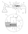
- FIG. 1 is an external perspective view of an abrasive tool to which the present invention is applied.
- the polishing tool 1 has a polishing brush 3 provided with a plurality of linear abrasives 2, and a polishing brush holder 4 for detachably holding the polishing brush 3.
- the polishing brush holder 4 includes a shank 6 connected to the machine tool 5 and a sleeve 7 coaxial with the shank 6.
- a large diameter portion 8 having a large diameter as compared with the shank 6 and the sleeve 7 is provided between the shank 6 and the sleeve 7.
- the polishing brush 3 is held by the polishing brush holder 4 in a state in which the end of the linear abrasive 2 is protruded from the sleeve 7.
- the shank 6 of the polishing brush holder 4 is connected to the spindle 5 a (see FIG. 4) of the machine tool 5.
- the machine tool 5 rotates the polishing tool 1 around the axis L of the shank 6. Further, the machine tool 5 brings the end portion of the linear abrasive 2 protruding from the sleeve 7 into contact with the workpiece W to cut or polish the workpiece W.
- the direction of the axis L of the shank 6 is taken as the direction of the axis L of the polishing tool 1.
- the side where the sleeve 7 is located is referred to as the front L1 of the polishing tool 1
- the side where the shank 6 is located is referred to as the rear L2 of the polishing tool 1.
- FIG. 2 is a perspective view of the polishing brush 3 provided in the polishing tool 1.
- FIG. 3 is an explanatory view showing a schematic structure of the polishing tool 1 of FIG. In FIG. 3, the polishing tool 1 is cut along the axis L.
- the polishing brush 3 has a plurality of linear abrasives 2 arranged in parallel, and a holder 11 for holding one end of the plurality of linear abrasives 2.
- the linear abrasive 2 is obtained by impregnating and curing a binder resin in a collection yarn of inorganic long fibers such as alumina long fibers.
- the holder 11 is an annular member provided with a holder through hole 12 extending in the direction of the axis L.
- the holder 11 is provided with a plurality of linear abrasive holding holes 13 at its front end surface. Each linear abrasive material holding hole 13 is circular.
- a plurality of linear abrasive material holding holes 13 are provided at equal angular intervals around the axis L and surround the holder through hole 12.
- the plurality of linear abrasives 2 are divided into a plurality and bundled.
- a bundle of abrasive material bundles 14 has its rear end (one end) inserted in the linear abrasive material holding hole 13.
- Each abrasive bundle 14 is fixed to the holder 11 by an adhesive filled in the linear abrasive holding holes 13.
- the holder 11 is provided at the rear end surface with a recess that surrounds the holder through hole 12.
- the recessed portion is a brush side connecting portion 15 for detachably mounting the polishing brush 3 to the polishing brush 3.
- the polishing brush holder 4 includes a shank 6, a support mechanism 21 for supporting the polishing brush 3 so as to be movable in the axis L direction, and a moving mechanism 22 for moving the polishing brush 3 in the axis L direction. Equipped with
- the support mechanism 21 includes a sleeve 7 and a coupling member 24 disposed in the sleeve 7 so as to be movable in the direction of the axis L.
- the sleeve 7 is cylindrical in shape.
- a flange 7a extending to the outer peripheral side is provided.
- the flange 7 a defines the front end face of the large diameter portion 8.
- the connecting member 24 includes a disk portion 25 provided with an annular facing surface 25 a facing the inner wall surface 7 b of the sleeve 7 with a slight gap, and a projection 26 projecting forward L 1 from the center of the disk portion 25.
- the protrusion 26 is a connecting portion having a shape fitted to the brush side connecting portion 15 of the polishing brush 3.
- the polishing brush 3 is detachably mounted to the polishing brush holder 4 by fitting the brush side connecting portion 15 to the connecting portion (protrusion 26) of the connecting member 24.
- the connecting member 24 also has a through hole 28 penetrating in the direction of the axis L.
- An internal thread 29 is provided on the inner peripheral surface of the through hole 28.
- the polishing brush 3 is supported by the support mechanism 21 so as to be movable in the direction of the axis L by being attached to the connecting member 24.
- the holder 11 is positioned in the sleeve 7, and the other front end portion (the other end portion, the free end) of the plurality of linear abrasives 2 protrudes from the sleeve 7 with the support mechanism 21. Supported by When the polishing brush 3 is mounted on the connecting member 24, the through hole 28 of the connecting member 24 and the holder through hole 12 communicate with each other.
- the inside diameter of the holder through hole 12 is larger than the inside diameter of the through hole 28 of the connecting member 24.
- the sleeve 7 is provided with a groove 31 extending in the direction of the axis L on the inner circumferential surface 7b.
- the connection member 24 is provided with a protrusion 32 that protrudes outward in the circumferential direction of the annular opposing surface 25 and extends in the axial line L direction.
- the connecting member 24 is disposed in the sleeve 7 in a state where the convex portion 32 is inserted into the groove 31 of the sleeve 7.
- the moving mechanism 22 includes a motor 35 as a drive source.
- the motor 35 is a stepping motor.
- the moving mechanism 22 also includes a shaft member 36 extending in the direction of the axis L, a support member 37 supporting the shaft member 36 so as to be movable in the direction of the axis L and rotatably about the axis L, and a shaft member that rotates the motor 35.
- the support member 37 is a disk-shaped member which spreads in a direction orthogonal to the axis L.
- the large diameter portion 8 includes a housing 18 having a cylindrical portion 16 and a sealing portion 17 that seals the rear end opening of the cylindrical portion 16.
- the shank 6 protrudes rearward L 2 from the central portion of the sealing portion 17.
- the support member 37 closes the front end opening of the cylindrical portion 16.
- An annular outer peripheral surface 37 a of the support member 37 located on the outer side in the radial direction orthogonal to the axis L constitutes the outer peripheral surface of the large diameter portion 8 together with the outer peripheral surface of the cylindrical portion 16.
- the motor 35 and the driving force transmission mechanism 38 are disposed in the space inside the large diameter portion 8 divided by the housing 18 and the support member 37.
- the support member 37 is located between the driving force transmission mechanism 38 and the connecting member 24 in the direction of the axis L.
- An axial hole 41 for supporting the axial member 36 penetrates at the center of the support member 37 in the direction of the axis L.
- the front surface of the support member 37 is fixed to the flange 7 a of the sleeve 7.
- the shaft member 36 penetrates the shaft hole 41 and penetrates the through hole 28 of the connection member 24 disposed in the sleeve 7. Further, the shaft member 36 extends forward through the holder through hole 12 of the polishing brush 3 mounted on the connecting member 24.
- the male screw 39 of the shaft member 36 is screwed into the female screw 29 of the through hole 28 of the connecting member 24.
- the groove portion 31 provided on the inner peripheral surface 7 b of the sleeve 7 and the convex portion 32 provided on the outer peripheral surface of the connecting member 24 constitute a rotation restricting mechanism 40.
- the driving force transmission mechanism 38 has a final gear 45 to which the driving force of the motor 35 is transmitted, an output gear 46 coaxially fixed to the shaft member 36 and meshed with the final gear 45, and the output gear 46 directed to the support member 37. And a biasing member 47.
- the final gear 45 is rotatably supported by a support shaft 48 extending from the support member 37 to the rear L2.
- the support shaft 48 is parallel to the shaft member 36. Therefore, the final gear 45 and the output gear 46 fixed to the shaft member 36 rotate around a parallel rotational axis.
- the output gear 46 is in contact with the support member 37 from the rear L 2 by the biasing force of the biasing member 47.
- the rotation axis of the shaft member 36 to which the output gear 46 is fixed and the final gear 45 is parallel. Therefore, even when the output gear 46 moves in the direction of the axis L, the meshing state between the output gear 46 and the final gear 45 is maintained. Thus, the rotation of the motor 35 is always transmitted to the output gear 46 via the driving force transmission mechanism 38. When the driving force of the motor 35 is transmitted to the output gear 46, the shaft member 36 rotates about the axis L.
- control system of the polishing brush holder 4 includes a control unit 51 including a CPU, and a non-volatile memory 52 connected to the control unit 51.
- a control program operated by the control unit 51 is stored and held in the non-volatile memory 52.
- the control unit 51 controls the movement of the polishing brush 3 by operating a control program.
- a pressure sensor 53 is connected to the input side of the control unit 51.
- the pressure sensor 53 is a load detector that detects a load applied to the polishing brush 3 from the side of the workpiece W when the workpiece W is polished by the polishing brush 3.
- the pressure sensor 53 contacts the shaft member 36 from the rear L 2 and detects the pressure applied to the shaft member 36.
- a motor 35 is connected to the output side of the control unit 51.
- the controller 51 determines that the output from the pressure sensor 53 (sensor detection pressure P) is lower than a predetermined first pressure threshold, it drives the motor 35 to move the polishing brush 3 forward L1.
- the controller 51 determines that the output from the pressure sensor 53 (sensor detection pressure P) is higher than a predetermined second pressure threshold, the controller 51 drives the motor 35 to move the polishing brush 3 rearward L2.
- the control unit 51 monitors the output from the pressure sensor 53 (sensor detection pressure P) while driving the motor 35 to move the polishing brush 3, and based on the monitored output, The driving is stopped to stop the movement of the polishing brush 3.
- the control unit 51 also includes a counting unit 54 that counts the number of movements every time the control unit 51 drives the motor 35 (moving mechanism 22) to move the polishing brush 3 forward L1, the control unit 51, and an external unit.
- a wireless communication unit 55 for performing communication with the device is connected.
- the counting unit 54 counts the number of drive steps input to the motor 35 in order to move the polishing brush 3 to the front L1, and inputs it to the control unit 51 as the number of movements.
- the counting unit 54 may be configured as part of the control unit 51. In this case, the control unit 51 counts the number of movements every time the drive signal for moving the polishing brush 3 to the front L1 is input to the motor 35.
- the wireless communication unit 55 communicates with an external device and the control unit 51 via, for example, a wireless network defined by the IEEE 802.11 standard.
- the control unit 51 transmits the output from the pressure sensor 53 (sensor detection pressure P: see FIG. 6) to an external device via the wireless communication unit 55.
- the control unit 51 also transmits the number of movements of the polishing brush 3 counted by the counting unit 54 to an external device via the wireless communication unit 55.
- the external device can rewrite the control program stored and held in the non-volatile memory 52 via the wireless network and the wireless communication unit 55.
- the polishing brush holder 4 includes a motor battery 57 (first power source) for supplying power to the motor 35 which is a drive source of the moving mechanism 22.
- the polishing brush holder 4 includes a control battery 51 (second power source) that supplies power to the control unit 51, the pressure sensor 53, the counting unit 54, and the wireless communication unit 55.
- the motor battery 57 and the control battery 58 can be charged by connecting a cable from the outside.
- the control unit 51, the non-volatile memory 52, the counting unit 54, the wireless communication unit 55, the battery 57 for motor, and the battery 58 for control are spaces inside the large diameter portion 8 partitioned by the housing 18 and the support member 37. Is located in
- the control unit 51 drives the motor 35 (moving mechanism 22) based on the output (sensor detection pressure P) from the pressure sensor 53 to move the polishing brush 3 in the direction of the axis L.
- FIG. 6 is a graph showing the sensor detection pressure P output from the pressure sensor 53 during the processing operation.
- the upper drawing shows a state in which the polishing tool 1 is connected to the machine tool 5 to process the workpiece W.
- FIG. 5 shows a state in which the cutting amount in which the machine tool 5 brings the linear abrasive 2 into contact with the workpiece W is appropriate during the processing operation.
- FIG. 5 shows a state in which the linear abrasive 2 is worn during the processing operation and the cutting amount in which the machine tool 5 brings the linear abrasive 2 into contact with the workpiece W is reduced.
- the machine tool 5 holds the free end of the linear abrasive 2 of the polishing brush 3 while maintaining the distance D between the spindle 5a and the work W constant. Is brought into contact with the work W to process the work W.
- the free end of the linear abrasive 2 of the polishing brush 3 is the workpiece W And the workpiece W is processed.
- the shaft member 36 exerts an urging force of the urging member 47. Has moved to the rear L2 against. That is, during the processing operation, a load (pressure F1) is applied to the polishing brush 3 from the side of the work W. Also, the load (pressure F1) is transmitted to the shaft member 36 via the connecting member 24. Accordingly, the shaft member 36 is moved rearward L2 against the biasing force of the biasing member 47 that biases the output gear 46. Accordingly, as shown at time t0 in FIG.
- the pressure sensor 53 detects a sensor detection pressure P1 corresponding to the load (pressure F1) applied to the polishing brush 3 from the side of the work W.
- the sensor detection pressure P1 corresponds to the difference between the pressure F1 and the biasing force of the biasing member 47.
- the pressure sensor 53 detects a sensor detection pressure P2 corresponding to the load (pressure F2) applied to the polishing brush 3 from the side of the work W.
- control unit 51 determines that the output from the pressure sensor 53 (sensor detection pressure P2) is lower than a predetermined first pressure threshold P3, the control unit 51 drives the motor 35 to set the polishing brush 3 forward L1. Move (see the two-dot chain arrow in FIG. 5). In other words, if the control unit 51 determines that the pressure F2 applied to the polishing brush 3 from the side of the work W on the basis of the output from the pressure sensor 53 (sensor detection pressure P) is lower than a predetermined set load The motor 35 is driven to move the polishing brush 3 forward L1.
- the control unit 51 monitors the output from the pressure sensor 53 (sensor detection pressure P) while moving the polishing brush 3 by driving the motor 35, and based on the monitored output, The driving is stopped to stop the movement of the polishing brush 3. As a result, as shown in FIG. 4, the machining accuracy of the polishing tool 1 with respect to the workpiece W is maintained with the cutting amount S2 close to the cutting amount S1.
- control unit 51 monitors the output from the pressure sensor 53 (sensor detection pressure P) while driving the motor 35 to move the polishing brush 3, and based on the monitored output. Since the driving of the motor 35 is stopped, the processing accuracy of the polishing tool 1 is obtained even if the processing performance of the polishing brush 3 for cutting or polishing the workpiece W changes due to the change of the total length of the linear abrasive 2 due to wear. Can maintain
- the control unit 51 monitors the output (sensor detection pressure P) from the pressure sensor 53 while the polishing brush 3 is moving, and as shown in FIG. 6, the sensor detection pressure P is a predetermined sensor detection pressure P4.
- the polishing brush 3 is stopped at time t2 (if the driving of the motor 35 is stopped), the amount of movement of the polishing brush 3 becomes large.
- the cutting amount in which the machine tool 5 brings the polishing brush 3 into contact with the work W is large. Therefore, even when the rigidity of the linear abrasive 2 is weak, the polishing brush 3 is a work W Maintain the processing accuracy to process the
- the control unit 51 monitors the output (sensor detection pressure P) from the pressure sensor 53 while the polishing brush 3 is moving, and as shown in FIG. 6, the sensor detection pressure P is a predetermined sensor detection pressure P4. If the movement of the polishing brush 3 is stopped at time t2 (if the driving of the motor 35 is stopped), the amount of movement of the polishing brush 3 is reduced.
- the dimensional error or the like of the work W causes the space between the spindle 5a and the work W to be increased. Even when the distance D is short and the workpiece W is subjected to excessive processing, the processing accuracy for the workpiece W can be maintained.
- the control unit 51 drives the motor 35 based on the output from the pressure sensor 53 (sensor detection pressure P) to move the polishing brush 3 rearward L2. That is, when the control unit 51 determines that the output from the pressure sensor 53 (sensor detection pressure P) is higher than the predetermined second pressure threshold P4, the control unit 51 drives the motor 35 to back L2 the polishing brush 3 Move to
- the control unit 51 monitors the output (sensor detection pressure P) from the pressure sensor 53 while the polishing brush 3 is moving, and when the sensor detection pressure P1 becomes a predetermined sensor detection pressure P4, If the movement is stopped, the amount of cutting in which the machine tool 5 brings the polishing brush 3 into contact with the work W becomes appropriate. Thereby, the processing accuracy with which the polishing brush 3 processes the workpiece W can be maintained.
- the machine tool 5 moves the spindle 5 a in the direction approaching the workpiece W in order to maintain the processing accuracy. There is no need to move it. That is, according to the present embodiment, the machine tool 5 can maintain the machining posture with the distance D between the spindle 5a and the workpiece W fixed during the machining operation.
- the polishing brush holder 4 since the polishing brush holder 4 is provided with the pressure sensor 53, the polishing brush 3 is attached to the polishing brush 3 from the side of the workpiece W while the polishing tool 1 connected to the machine tool 5 cuts or polishes the workpiece W. Such load (pressure) can be detected. Further, the control unit 51 of the polishing brush holder 4 drives the moving mechanism 22 based on the output (sensor detection pressure P) from the pressure sensor 53 to move the polishing brush 3 in the direction of the axis L. Thus, the polishing tool 1 can maintain the processing accuracy of polishing or cutting the workpiece W even when the linear abrasive 2 of the polishing brush 3 is worn.
- the machine tool 5 when machining is started with the distance D between the spindle 5a and the workpiece W maintained constant, the distance between the spindle 5a and the workpiece W due to dimensional error of the workpiece W, etc. Even when D is short and the workpiece W is subjected to excessive processing, the processing accuracy for the workpiece W can be maintained.
- the machine tool 5 can keep the distance D between the spindle 5a and the work W constant during the machining operation, the machining attitude can be maintained. Therefore, the machine tool 5 can process the workpiece W without being affected by the static accuracy of the machine tool 5. Therefore, in the processing operation in which the machine tool 5 mounted on the polishing tool 1 processes the workpiece W, the processing operation can be easily kept constant from the start time point to the end time point of the processing operation.
- the machine tool 5 keeps the distance D between the spindle 5a and the work W constant during the machining operation. Therefore, it can be avoided that the machine tool 5 brings the polishing tool 1 close to the workpiece W despite the fact that the total length of the linear abrasive 2 is excessively short. Thereby, the interference accident in which the sleeve 7 of the grinding
- control unit 51 transmits the number of movements of the polishing brush 3 counted by the counting unit 54 to an external device via the wireless communication unit 55. Therefore, in the external device which has received the number of movements, the worn state of the linear abrasive 2 of the polishing brush 3 can be grasped based on the number of movements. Therefore, the replacement time of the polishing brush 3 can be grasped.
- control unit 51 transmits the output from the pressure sensor 53 (sensor detection pressure P) to an external device via the wireless communication unit 55. Therefore, it is possible to monitor the state of the load applied to the polishing brush 3 from the side of the work W by the external device to grasp the state of the load.
- the processing state in the previous process performed on the work W before the polishing process by the polishing tool 1 for example, occurred in the previous process It becomes possible to grasp the state such as the size of the burr.
- the polishing brush holder 4 includes the motor battery 57 and the control battery 58. Therefore, it is not necessary to supply power to the polishing brush holder 4 from the outside. Therefore, it is easy to rotate the polishing tool 1 in a state of being connected to the spindle 5 a of the machine tool 5.
- the motor battery 57 and the control battery 58 may be wirelessly chargeable. Further, the motor battery 57 and the control battery 58 are detachable with respect to the polishing brush holder 4 and can be replaced. Furthermore, power may be supplied from the outside without holding the motor battery 57 and the control battery 58 in the polishing brush holder 4.
- the motor battery 57 and the control battery 58 can be used as one battery, and power can be supplied from the same power supply.
- the wireless communication unit 55 can also communicate between an external device and the control unit 51 via infrared communication, Bluetooth (registered trademark), or the like.
- the rotation restricting mechanism 40 that restricts relative rotation of the connecting member 24 and the sleeve 7 about the axis L is a recess provided on the inner peripheral surface 7 b of the sleeve 7 and the outer peripheral surface of the connecting member 24.
- the configuration of the rotation restricting mechanism 40 is not limited to this.
- the sleeve 7 is provided on the inner peripheral surface 7b with a convex portion 32 which protrudes to the inner peripheral side and extends in the direction of the axis L
- the connecting member 24 has a facing surface 25 facing the inner peripheral surface 7b of the sleeve 7. You may provide the groove part 31 extended to an axis L direction.
- the rotation restricting mechanism 40 is configured by arranging the connecting member 24 in the sleeve 7 with the convex portion 32 of the sleeve 7 inserted in the groove 31. Further, for example, the rotation restricting mechanism 40 is configured by making the sleeve 7 into a rectangular tube shape and making the shape of the holder 11 of the polishing brush 3 seen from the direction of the axis L a polygon corresponding to the shape of the sleeve 7. It can also be done.
- a direct drive mechanism may be employed in which the shaft member 36 is directly driven by the motor 35.
- the rotor (output shaft) of the motor 35 is coaxially connected to the rear side L2 of the shaft member 36.
- the driving force transmission mechanism 38 is a connecting member that connects the rotor (output shaft) of the motor 35 and the shaft member 36.
- the rotor in the motor 35, the rotor is supported so as to be movable in the direction of the axis L, and the pressure sensor 53 is brought into contact with the rotor from the rear L2.
- the pressure sensor 53 detects the pressure applied to the rotor of the motor 3 as a load applied to the polishing brush 3 from the side of the work W.
- a vibration detector that detects the vibration of the polishing brush 3 supported by the support mechanism 21 may be used as a load detector. That is, since the front end portion of the linear abrasive 2 of the polishing brush 3 is in contact with the workpiece W during the processing operation, when the load applied to the polishing brush 3 from the workpiece W changes, the polishing brush 3 Vibration changes. Therefore, if the vibration detector is used, the load applied to the polishing brush 3 from the side of the work W can be detected.
- the vibration detector can detect the vibration of the polishing brush 3 by detecting the vibration of the rear end of the shaft member 36, for example.
- a sound wave detector that detects the amplitude of the sound generated in the polishing brush 3 supported by the support mechanism 21 can be used as a load detector. That is, since the front end portion of the linear abrasive 2 of the polishing brush 3 is in contact with the workpiece W during the processing operation, when the load applied to the polishing brush 3 from the workpiece W changes, the polishing brush 3 Vibration changes. In addition, when the vibration of the polishing brush 3 changes, the amplitude of the sound generated in the polishing brush 3 changes. Therefore, the load applied to the polishing brush 3 from the side of the work W can be detected by using the sound wave detector.
- the polishing brush 3 when the polishing brush 3 is excessively worn during the processing operation and the position of the front end 2a of the linear abrasive 2 moves in a direction away from the work W, the work is applied to the polishing brush 3 from the side As the load decreases, the vibration of the polishing brush 3 decreases. Therefore, the amplitude of the sound generated in the polishing brush 3 is reduced.
- the moving mechanism 22 when the moving mechanism 22 is driven to move the polishing brush 3 forward L1, the amount of cutting increases and the load applied to the polishing brush 3 from the side of the work W increases. Vibration increases. Therefore, the amplitude of the sound generated in the polishing brush 3 becomes large.
Landscapes
- Engineering & Computer Science (AREA)
- Mechanical Engineering (AREA)
- Finish Polishing, Edge Sharpening, And Grinding By Specific Grinding Devices (AREA)
- Constituent Portions Of Griding Lathes, Driving, Sensing And Control (AREA)
- Polishing Bodies And Polishing Tools (AREA)
Abstract
L'invention concerne un dispositif de polissage (1) qui comprend une brosse de polissage (3) et un support (4) de brosse de polissage qui maintient la brosse de polissage (3). Le support (4) de brosse de polissage comprend une tige (6), un mécanisme de support (21) doté d'un manchon (7) et supporte la brosse de polissage (3) de façon à être mobile dans une direction axiale L de la tige (6), et un mécanisme de déplacement (22) qui déplace la brosse de polissage (3) dans la direction axiale L. Le support (4) de brosse de polissage comprend un capteur de pression (53) qui détecte une charge (pression de détection de capteur (P)) appliquée à la brosse de polissage (3) par une pièce (W) lorsque la pièce (W) est polie par la brosse de polissage (3) supportée par le mécanisme de support (21), et une unité de commande (51) qui entraîne le mécanisme de déplacement (22) sur la base de la sortie (pression de détection de capteur (P)) provenant du capteur de pression (53) pour déplacer la brosse de polissage (3) dans la direction axiale L.
Priority Applications (8)
| Application Number | Priority Date | Filing Date | Title |
|---|---|---|---|
| PCT/JP2018/000340 WO2019138471A1 (fr) | 2018-01-10 | 2018-01-10 | Support de brosse de polissage et dispositif de polissage |
| EP18899985.8A EP3738714A4 (fr) | 2018-01-10 | 2018-06-14 | Support d'outil de polissage et dispositif de polissage |
| KR1020207019650A KR102509429B1 (ko) | 2018-01-10 | 2018-06-14 | 연마구 홀더 및 연마 공구 |
| CN201880086153.9A CN111565891B (zh) | 2018-01-10 | 2018-06-14 | 研磨具支架以及研磨工具 |
| PCT/JP2018/022754 WO2019138595A1 (fr) | 2018-01-10 | 2018-06-14 | Support d'outil de polissage et dispositif de polissage |
| US16/766,200 US11559873B2 (en) | 2018-01-10 | 2018-06-14 | Polishing tool holder and polishing device |
| JP2019564279A JP7142848B2 (ja) | 2018-01-10 | 2018-06-14 | 研磨具ホルダおよび研磨工具 |
| TW107135161A TWI801428B (zh) | 2018-01-10 | 2018-10-05 | 研磨具支架及研磨工具 |
Applications Claiming Priority (1)
| Application Number | Priority Date | Filing Date | Title |
|---|---|---|---|
| PCT/JP2018/000340 WO2019138471A1 (fr) | 2018-01-10 | 2018-01-10 | Support de brosse de polissage et dispositif de polissage |
Publications (1)
| Publication Number | Publication Date |
|---|---|
| WO2019138471A1 true WO2019138471A1 (fr) | 2019-07-18 |
Family
ID=67218534
Family Applications (2)
| Application Number | Title | Priority Date | Filing Date |
|---|---|---|---|
| PCT/JP2018/000340 WO2019138471A1 (fr) | 2018-01-10 | 2018-01-10 | Support de brosse de polissage et dispositif de polissage |
| PCT/JP2018/022754 WO2019138595A1 (fr) | 2018-01-10 | 2018-06-14 | Support d'outil de polissage et dispositif de polissage |
Family Applications After (1)
| Application Number | Title | Priority Date | Filing Date |
|---|---|---|---|
| PCT/JP2018/022754 WO2019138595A1 (fr) | 2018-01-10 | 2018-06-14 | Support d'outil de polissage et dispositif de polissage |
Country Status (7)
| Country | Link |
|---|---|
| US (1) | US11559873B2 (fr) |
| EP (1) | EP3738714A4 (fr) |
| JP (1) | JP7142848B2 (fr) |
| KR (1) | KR102509429B1 (fr) |
| CN (1) | CN111565891B (fr) |
| TW (1) | TWI801428B (fr) |
| WO (2) | WO2019138471A1 (fr) |
Families Citing this family (10)
| Publication number | Priority date | Publication date | Assignee | Title |
|---|---|---|---|---|
| DE102017115540B4 (de) * | 2017-07-11 | 2024-08-22 | Gühring KG | Entgratwerkzeug und Verfahren zum Entgraten |
| US11162241B2 (en) * | 2018-03-27 | 2021-11-02 | Deere & Company | Controlling mobile machines with a robotic attachment |
| DE102020104238A1 (de) * | 2020-02-18 | 2021-08-19 | Berliner Glas GmbH | Verfahren und Poliervorrichtung zur Bearbeitung eines plattenförmigen Bauteils, und plattenförmiges Bauteil, insbesondere elektrostatische Haltevorrichtung oder Immersions-Wafertafel |
| CN112123173B (zh) * | 2020-09-25 | 2021-08-27 | 山东理工职业学院 | 家具异形件自动加工磨削抛光机 |
| US20240082984A1 (en) * | 2020-12-25 | 2024-03-14 | Xebec Technology Co., Ltd. | Method of controlling polishing tool holder, polishing tool holder, and polishing device |
| TWI764531B (zh) * | 2021-01-21 | 2022-05-11 | 主力欣企業股份有限公司 | 兼具有刀柄可重複回收使用與可轉換刃口角度之砂輪鑽石修刀結構 |
| WO2024018562A1 (fr) * | 2022-07-20 | 2024-01-25 | 株式会社ジーベックテクノロジー | Système et programme |
| JP7239951B1 (ja) | 2022-08-02 | 2023-03-15 | 大明化学工業株式会社 | スティック砥石および研磨方法 |
| KR102615355B1 (ko) | 2023-10-20 | 2023-12-20 | (주)대영에스지 | 내경 연마 홀더 |
| KR102617516B1 (ko) | 2023-10-20 | 2023-12-27 | (주)대영에스지 | 외경 연마 홀더 |
Citations (7)
| Publication number | Priority date | Publication date | Assignee | Title |
|---|---|---|---|---|
| JPH0179553U (fr) * | 1987-11-10 | 1989-05-29 | ||
| JPH10286772A (ja) * | 1997-04-09 | 1998-10-27 | Nikon Corp | 研磨工具および研削工具 |
| JP2003311535A (ja) * | 2002-02-25 | 2003-11-05 | Makino Fraes Seiki Kk | Nc研削盤 |
| JP2005169589A (ja) * | 2003-12-12 | 2005-06-30 | Honda Motor Co Ltd | 無段変速機の無端ベルト用金属リングの研磨方法 |
| WO2016021460A1 (fr) * | 2014-08-05 | 2016-02-11 | 新東工業株式会社 | Dispositif et procédé de polissage à la brosse |
| JP2016087757A (ja) * | 2014-11-07 | 2016-05-23 | 株式会社ディスコ | スピンドルユニット |
| JP2017100274A (ja) * | 2015-11-20 | 2017-06-08 | 株式会社ジーベックテクノロジー | 工具ホルダおよび研磨工具ユニット |
Family Cites Families (36)
| Publication number | Priority date | Publication date | Assignee | Title |
|---|---|---|---|---|
| US3780407A (en) * | 1971-12-02 | 1973-12-25 | J Hoffecker | Metal working brush assembly |
| US4561214A (en) * | 1978-10-12 | 1985-12-31 | Inoue-Japax Research Incorporated | Abrading tool |
| JPH0663899B2 (ja) * | 1987-12-25 | 1994-08-22 | 日立精工株式会社 | 動的バランサ |
| JP2827540B2 (ja) * | 1991-03-11 | 1998-11-25 | 松下電器産業株式会社 | 研磨スピンドル |
| JPH07100754A (ja) | 1993-09-30 | 1995-04-18 | Melco:Kk | 自動金型研磨装置 |
| JP3342128B2 (ja) * | 1993-10-21 | 2002-11-05 | マツダ株式会社 | 塗膜欠陥位置マーキング装置 |
| JPH1044037A (ja) * | 1996-07-31 | 1998-02-17 | Riken Seiko Kk | 研削加工装置 |
| NZ314024A (en) * | 1997-01-06 | 1999-03-29 | Norton Co | Wire brush attachment, for angle grinder or hand-held drill, with at least one aperture therethrough |
| US5932040A (en) * | 1997-10-01 | 1999-08-03 | Bibielle S.P.A. | Method for producing a ring of abrasive elements from which to form a rotary brush |
| US6846226B2 (en) * | 2000-06-28 | 2005-01-25 | Michael Kapgan | Burr removal apparatus |
| TW448810U (en) * | 2000-07-10 | 2001-08-01 | Taiwan Power Co | Mechanism for automatically controlling position/force |
| US20020197941A1 (en) * | 2001-06-20 | 2002-12-26 | Bruno Antonino F. | Flexible adapter for use with rotary tools |
| JP2003031530A (ja) * | 2001-07-13 | 2003-01-31 | Tokyo Seimitsu Co Ltd | ウェーハ研磨装置 |
| JP3975073B2 (ja) * | 2001-11-01 | 2007-09-12 | 株式会社ジーベックテクノロジー | 研磨機用ブラシ |
| KR101011911B1 (ko) * | 2002-07-22 | 2011-02-01 | 다이메이카가쿠코교가부시키가이샤 | 브러시형 숫돌의 제조 방법, 브러시형 숫돌, 및 연마기용 브러시 |
| KR20060015557A (ko) * | 2003-04-28 | 2006-02-17 | 스티븐 제임스 크램톤 | 외골격을 구비한 cmm 암 |
| JP2007168051A (ja) * | 2005-12-26 | 2007-07-05 | Jtekt Corp | 内面研削盤 |
| US8607399B2 (en) * | 2006-05-17 | 2013-12-17 | Richard T. Umbrell | Quick release connector for a single or dual-sided pad |
| US7840305B2 (en) * | 2006-06-28 | 2010-11-23 | 3M Innovative Properties Company | Abrasive articles, CMP monitoring system and method |
| JP5113422B2 (ja) * | 2007-05-23 | 2013-01-09 | 富士精工株式会社 | 押圧力検出装置付ローラバニシング装置 |
| JP4972492B2 (ja) | 2007-08-28 | 2012-07-11 | 株式会社ジーベックテクノロジー | 研磨機用ブラシ |
| CN102310359B (zh) * | 2010-07-01 | 2014-08-20 | 本田技研工业株式会社 | 金属环研磨装置以及金属环研磨方法 |
| CN101983838B (zh) * | 2010-10-14 | 2012-07-25 | 复旦大学 | 基于智能数控平台的铣磨抛光装置 |
| FR2980386B1 (fr) * | 2011-09-27 | 2014-09-12 | Visioptimum Internat | Dispositif de polissage de lentilles optiques |
| CN103056759B (zh) * | 2012-12-24 | 2015-01-28 | 中国科学院自动化研究所 | 一种基于传感器反馈的机器人磨削系统 |
| US9017141B2 (en) * | 2013-01-04 | 2015-04-28 | White Drive Products, Inc. | Deburring machine and method for deburring |
| US9597766B2 (en) * | 2013-02-05 | 2017-03-21 | Sintokogio, Ltd. | Brush unit, a device for brush-polishing that uses the brush unit, a system for brush-polishing, and a method for brush-polishing |
| JP6273818B2 (ja) * | 2013-12-13 | 2018-02-07 | アイシン精機株式会社 | 研磨用ブラシ及びそれを用いた工作機械 |
| DE112015002410T5 (de) * | 2014-05-22 | 2017-02-02 | Taimei Chemicals Co., Ltd | Werkzeughalter, Polierwerkzeug, Polierwerkzeugeinheit und Verfahren zum Einstellen des Überstands eines Schleifelements |
| JP6465404B2 (ja) | 2015-06-23 | 2019-02-06 | 株式会社Ihi | 基準面倣い治具とこれを用いる仕上げ加工装置及び方法 |
| US9750387B2 (en) * | 2015-11-12 | 2017-09-05 | Darby Taylor | Selectably attachable buffing pad |
| CN105598805B (zh) * | 2015-12-28 | 2018-07-20 | 北京中电科电子装备有限公司 | 一种晶圆干式抛光装置及方法 |
| US10350722B2 (en) * | 2016-02-05 | 2019-07-16 | Toshiba Kikai Kabushiki Kaisha | Polishing apparatus |
| CN105945716B (zh) * | 2016-05-04 | 2017-09-19 | 中国电子科技集团公司第四十五研究所 | 抛光头进给加压抛光方法、控制器及进给加压机构 |
| CN206445627U (zh) * | 2016-12-30 | 2017-08-29 | 广州蓝圣智能科技有限公司 | 门框a级面打磨专机 |
| CN107433513B (zh) * | 2017-08-26 | 2023-05-26 | 广东利迅达机器人系统股份有限公司 | 一种打磨力控装置及设置有该装置的打磨机 |
-
2018
- 2018-01-10 WO PCT/JP2018/000340 patent/WO2019138471A1/fr active Application Filing
- 2018-06-14 JP JP2019564279A patent/JP7142848B2/ja active Active
- 2018-06-14 KR KR1020207019650A patent/KR102509429B1/ko active IP Right Grant
- 2018-06-14 CN CN201880086153.9A patent/CN111565891B/zh active Active
- 2018-06-14 US US16/766,200 patent/US11559873B2/en active Active
- 2018-06-14 WO PCT/JP2018/022754 patent/WO2019138595A1/fr unknown
- 2018-06-14 EP EP18899985.8A patent/EP3738714A4/fr active Pending
- 2018-10-05 TW TW107135161A patent/TWI801428B/zh active
Patent Citations (7)
| Publication number | Priority date | Publication date | Assignee | Title |
|---|---|---|---|---|
| JPH0179553U (fr) * | 1987-11-10 | 1989-05-29 | ||
| JPH10286772A (ja) * | 1997-04-09 | 1998-10-27 | Nikon Corp | 研磨工具および研削工具 |
| JP2003311535A (ja) * | 2002-02-25 | 2003-11-05 | Makino Fraes Seiki Kk | Nc研削盤 |
| JP2005169589A (ja) * | 2003-12-12 | 2005-06-30 | Honda Motor Co Ltd | 無段変速機の無端ベルト用金属リングの研磨方法 |
| WO2016021460A1 (fr) * | 2014-08-05 | 2016-02-11 | 新東工業株式会社 | Dispositif et procédé de polissage à la brosse |
| JP2016087757A (ja) * | 2014-11-07 | 2016-05-23 | 株式会社ディスコ | スピンドルユニット |
| JP2017100274A (ja) * | 2015-11-20 | 2017-06-08 | 株式会社ジーベックテクノロジー | 工具ホルダおよび研磨工具ユニット |
Also Published As
| Publication number | Publication date |
|---|---|
| WO2019138595A1 (fr) | 2019-07-18 |
| KR102509429B1 (ko) | 2023-03-10 |
| CN111565891B (zh) | 2022-05-13 |
| TW201930006A (zh) | 2019-08-01 |
| CN111565891A (zh) | 2020-08-21 |
| US20200368876A1 (en) | 2020-11-26 |
| US11559873B2 (en) | 2023-01-24 |
| TWI801428B (zh) | 2023-05-11 |
| JPWO2019138595A1 (ja) | 2021-01-14 |
| JP7142848B2 (ja) | 2022-09-28 |
| EP3738714A1 (fr) | 2020-11-18 |
| EP3738714A4 (fr) | 2021-10-13 |
| KR20200098587A (ko) | 2020-08-20 |
Similar Documents
| Publication | Publication Date | Title |
|---|---|---|
| WO2019138471A1 (fr) | Support de brosse de polissage et dispositif de polissage | |
| JP5518679B2 (ja) | 回転工具 | |
| JP6273818B2 (ja) | 研磨用ブラシ及びそれを用いた工作機械 | |
| JP6557221B2 (ja) | 工具ホルダ、研磨工具、研磨工具ユニットおよび砥材突き出し量調整方法 | |
| JP6691130B2 (ja) | プログラム制御の工作機械のためのスピンドル装置 | |
| EP2529895A1 (fr) | Outil motorisé | |
| JP6403589B2 (ja) | 作業工具 | |
| JP5891107B2 (ja) | 工作機械 | |
| JP7039029B2 (ja) | 加工装置 | |
| JP6269035B2 (ja) | 切削用工具及びそれを用いた工作機械 | |
| WO2022004124A1 (fr) | Brosse de polissage et procédé de polissage | |
| EP3156187A1 (fr) | Outil d'usinage rotatif | |
| KR101972453B1 (ko) | 공작기계의 c축 브레이크 장치 | |
| KR102217335B1 (ko) | 건드릴 머신의 숏드릴 연결구조 | |
| CN110769976B (zh) | 作业工具 | |
| JP6792627B2 (ja) | 電動工具 | |
| WO2024023876A1 (fr) | Support d'outil de polissage, outil de polissage et système de polissage | |
| US20240082984A1 (en) | Method of controlling polishing tool holder, polishing tool holder, and polishing device | |
| JP2019000958A (ja) | 電動工具 | |
| JP4194109B2 (ja) | せり出し装置付きブラシホルダ | |
| CN111515813A (zh) | 一种连接装置及设置该连接装置的工具单元 | |
| CN112823077A (zh) | 安全制动设备 | |
| JP2017154195A (ja) | 作業機 |
Legal Events
| Date | Code | Title | Description |
|---|---|---|---|
| 121 | Ep: the epo has been informed by wipo that ep was designated in this application |
Ref document number: 18899973 Country of ref document: EP Kind code of ref document: A1 |
|
| NENP | Non-entry into the national phase |
Ref country code: DE |
|
| 122 | Ep: pct application non-entry in european phase |
Ref document number: 18899973 Country of ref document: EP Kind code of ref document: A1 |
|
| NENP | Non-entry into the national phase |
Ref country code: JP |