WO2019131565A1 - 内燃機関用のスパークプラグ - Google Patents
内燃機関用のスパークプラグ Download PDFInfo
- Publication number
- WO2019131565A1 WO2019131565A1 PCT/JP2018/047406 JP2018047406W WO2019131565A1 WO 2019131565 A1 WO2019131565 A1 WO 2019131565A1 JP 2018047406 W JP2018047406 W JP 2018047406W WO 2019131565 A1 WO2019131565 A1 WO 2019131565A1
- Authority
- WO
- WIPO (PCT)
- Prior art keywords
- insulator
- inclined surface
- housing
- plug
- spark plug
- Prior art date
- Legal status (The legal status is an assumption and is not a legal conclusion. Google has not performed a legal analysis and makes no representation as to the accuracy of the status listed.)
- Ceased
Links
Images


Classifications
-
- H—ELECTRICITY
- H01—ELECTRIC ELEMENTS
- H01T—SPARK GAPS; OVERVOLTAGE ARRESTERS USING SPARK GAPS; SPARKING PLUGS; CORONA DEVICES; GENERATING IONS TO BE INTRODUCED INTO NON-ENCLOSED GASES
- H01T13/00—Sparking plugs
- H01T13/20—Sparking plugs characterised by features of the electrodes or insulation
- H01T13/32—Sparking plugs characterised by features of the electrodes or insulation characterised by features of the earthed electrode
-
- H—ELECTRICITY
- H01—ELECTRIC ELEMENTS
- H01T—SPARK GAPS; OVERVOLTAGE ARRESTERS USING SPARK GAPS; SPARKING PLUGS; CORONA DEVICES; GENERATING IONS TO BE INTRODUCED INTO NON-ENCLOSED GASES
- H01T13/00—Sparking plugs
- H01T13/20—Sparking plugs characterised by features of the electrodes or insulation
- H01T13/34—Sparking plugs characterised by features of the electrodes or insulation characterised by the mounting of electrodes in insulation, e.g. by embedding
Definitions
- the present disclosure relates to a spark plug for an internal combustion engine.
- a spark plug is used as an ignition means in an internal combustion engine such as an automobile engine.
- a spark plug in which a center electrode and a ground electrode are opposed to each other to form a discharge gap. Such a spark plug generates a discharge in the discharge gap, and the discharge ignites the mixture in the combustion chamber.
- a flow of air-fuel mixture such as a tumble flow is formed, and the discharge spark can be stretched by the flow by appropriately flowing this flow also in the discharge gap.
- the contact area between the discharge spark and the mixture in the combustion chamber can be obtained, and the ignitability of the mixture can be secured.
- the spark plug described in Patent Document 1 reduces the diameter of the outer peripheral surface of the distal end portion of the housing exposed in the combustion chamber toward the distal end side in the plug axial direction so as to easily guide the air flow to the discharge gap. It is an inclined slope. Thus, the air flow in the combustion chamber is guided by the inclined surface of the housing and tends to be directed to the discharge gap.
- the front end portion of the insulator is configured not to be exposed to the front end side of the housing. Therefore, conductive carbon generated by incomplete combustion in the combustion chamber is likely to flow into the space between the tip of the insulator and the housing. Therefore, carbon is likely to be deposited on the surface of the tip of the insulator. In such a case, a so-called cross spark problem occurs in which a discharge is generated between the center electrode and the housing through the carbon deposited on the surface of the tip of the insulator.
- the present disclosure is intended to provide a spark plug for an internal combustion engine which is less likely to cause side jump and which can easily improve the ignitability of the mixture in the combustion chamber.
- One aspect of the present disclosure is a tubular housing; A cylindrical insulator held inside the housing; A center electrode held inside the insulator; A ground electrode having a gap forming surface that forms a discharge gap with the tip surface of the center electrode;
- the insulator has a forceps protrusion protruding toward the tip end of the housing, The outer peripheral surface of the forceps projection portion is directed toward the inner peripheral side toward the tip end side in the plug axial direction in an axial parallel cross section which is a cross section passing through the plug central axis and parallel to the plug axial direction.
- the insulator protruding portion of the insulator protrudes toward the front end side of the housing. Therefore, carbon is less likely to be deposited on the surface of the insulator protrusion of the insulator. Therefore, it is possible to suppress the occurrence of side sparks.
- the outer peripheral surface of the forceps projecting portion has, in the axis parallel cross section, an inclined surface which is a linear shape or a curved shape convex toward the inner peripheral side toward the inner peripheral side toward the tip end side in the plug axial direction. Furthermore, in the axial parallel cross section, the imaginary straight lines passing through the both ends of the insulator inclined surface are formed to pass through the gap forming surface of the ground electrode. Therefore, the air flow in the combustion chamber flows along the insulator ramp and is directed to blow through the discharge gap. Therefore, the air flow can be made to flow appropriately in the discharge gap. Therefore, it is easy to stretch the discharge spark, and it is easy to improve the ignitability of the mixture in the combustion chamber.
- the air flow in the combustion chamber is guided by the insulator inclined surface so as to flow obliquely toward the tip end of the discharge gap. Therefore, the discharge sparks are stretched by the air flow obliquely towards the tip end, ie towards the center of the combustion chamber. In other words, the discharge sparks are stretched away from the engine head. Therefore, it is easy to suppress the heat of the flame generated by being ignited by the discharge spark from the discharge spark to the engine head, and it is easy to grow the flame.
- the flow direction of the air flow is guided by the insulator inclined surface formed on the insulator located closer to the discharge gap than the housing. Therefore, it is possible to allow the air flow to flow toward the discharge gap at an angle close to the plug axial direction. Therefore, it is easy to stretch the discharge spark toward the tip end side, and it is easy to further improve the ignitability.
- FIG. 1 is a cross-sectional view of a spark plug in Embodiment 1;
- FIG. 2 is a cross-sectional view of the periphery of a tip portion of a spark plug attached to an internal combustion engine in Embodiment 1;
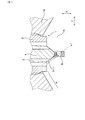
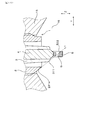
- FIG. 3 is a side view in the vicinity of the tip of the spark plug in the first embodiment;
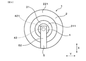
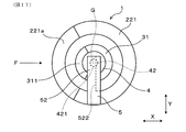
- FIG. 4 is a plan view of a portion of a spark plug exposed to an internal combustion engine according to Embodiment 1, viewed from the tip side, FIG.
- FIG. 5 is an explanatory cross-sectional view of the periphery of a tip end portion of the spark plug, for explaining the flow of the air flow flowing into the spark plug in the first embodiment
- FIG. 6 is an explanatory cross-sectional view of the periphery of a tip portion of a spark plug, for explaining how a discharge spark is stretched in the first embodiment
- FIG. 7 is a cross-sectional view of the periphery of a tip portion of a spark plug attached to an internal combustion engine in a second embodiment
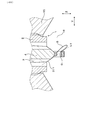
- FIG. 8 is a side view of the periphery of the tip of the spark plug in Embodiment 2;
- FIG. 9 is a cross-sectional view of the periphery of a tip portion of a spark plug attached to an internal combustion engine in a third embodiment
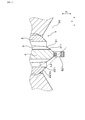
- FIG. 10 is a side view of the periphery of the tip of the spark plug in the third embodiment
- FIG. 11 is an explanatory cross-sectional view of the vicinity of the tip of the spark plug, for explaining the flow of the air flow around the discharge gap in the third embodiment
- FIG. 12 is an explanatory cross-sectional view of the periphery of a tip portion of a spark plug showing an initial discharge spark in the third embodiment
- FIG. 13 is an explanatory cross-sectional view of the periphery of a front end portion of a spark plug, showing how a ground point side point of a discharge spark moves on a ground inclined surface in Embodiment 3;
- FIG. 14 is an explanatory cross-sectional view of the periphery of a front end portion of a spark plug, showing a state when the ground side starting point of the discharge spark has moved to the front end portion of the ground inclined surface in Embodiment 3;
- FIG. 15 is a cross-sectional view of the periphery of a tip portion of a spark plug attached to an internal combustion engine in a fourth embodiment, FIG.
- FIG. 16 is a cross-sectional view of the periphery of a tip portion of a spark plug attached to an internal combustion engine in a fifth embodiment
- FIG. 17 is a plan view of a portion of a spark plug exposed to an internal combustion engine according to a fifth embodiment, viewed from the tip side
- FIG. 18 is a cross-sectional view of the periphery of a tip portion of a spark plug attached to an internal combustion engine in a sixth embodiment
- FIG. 19 is a cross-sectional view of the vicinity of the tip of a spark plug mounted on an internal combustion engine, showing a modified embodiment
- FIG. 20 is a cross-sectional view of the periphery of a tip portion of a spark plug mounted on an internal combustion engine, showing another modified embodiment.
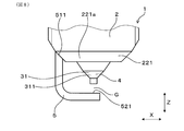
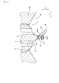
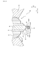
- the spark plug 1 for an internal combustion engine of the present embodiment has a housing 2, an insulator 3, a center electrode 4 and a ground electrode 5 as shown in FIG. 1.
- the housing 2 has a tubular shape.
- the insulator 3 is held inside the housing 2.
- the insulator 3 has a cylindrical shape.
- the center electrode 4 is held inside the insulator 3.
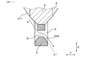
- the ground electrode 5 has a gap forming surface 521 which forms a discharge gap G with the tip end surface 421 of the center electrode 4.
- the insulator 3 has a forceps projecting portion 31 projecting to the front end side of the housing 2.
- at least one cross section of the cross sections passing through the plug central axis and parallel to the plug axial direction Z is referred to as an axis parallel cross section.
- the outer peripheral surface of the forceps protrusion 31 is a straight line or a curved line convex toward the inner periphery toward the tip side in the plug axial direction Z in the axis parallel cross section. It has a ladder inclined surface 311 which becomes.
- an imaginary straight line L1 passing through both ends of the insulator inclined surface 311 passes through the gap forming surface 521.
- FIG. 2 is an example of an axial parallel cross section.
- the present embodiment will be described in detail.
- the plug central axis means the central axis of the spark plug 1.
- the plug axial direction Z means the axial direction of the spark plug 1.
- the radial direction of the spark plug 1 is meant.
- the term “inner side” means the inner side in the plug radial direction, and the term “outer side” means the outer side in the plug radial direction.
- the spark plug 1 can be used, for example, as an ignition means in an internal combustion engine such as a car or a cogeneration.
- an ignition coil (not shown)
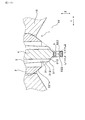
- the other end is disposed in a combustion chamber 16 of an internal combustion engine as shown in FIG.
- the side connected to the ignition coil in the plug axial direction Z is referred to as the proximal side
- the side disposed in the combustion chamber 16 is referred to as the distal side.
- the housing 2 has, at its tip, a mounting screw portion 21 for mounting in a female screw hole 11 provided in the engine head 15.
- the housing 2 has an annular housing distal end portion 22 that protrudes to the distal end side than the mounting screw portion 21.
- the tip of the housing tip 22 constitutes a housing exposure portion 221 exposed in the combustion chamber 16.
- the front end surface of the housing exposed portion 221 is a surface orthogonal to the plug axial direction Z.
- the insulator 3 is formed, for example, of alumina in a substantially cylindrical shape. As shown in FIG. 1, the insulator 3 has an axial hole 30 formed to penetrate in the plug axial direction Z. In the insulator 3, the tip end portion (i.e., the forceps protrusion portion 31) is protruded to the tip end side of the housing 2 in the plug axial direction Z. In addition, the insulator 3 has a proximal end portion projecting to the proximal end of the housing 2.
- the outer peripheral surface of the forceps projecting portion 31 has a forceps inclined surface 311 formed in a straight line so as to be directed to the inner peripheral side toward the tip end side in the axis parallel cross section.
- the outer peripheral surface of the forceps protrusion portion 31 has a forceps inclined surface 311 at least in an axial parallel cross section parallel to both the plug axial direction Z and the lateral direction Y.
- the outer circumferential surface of the forceps protrusion portion 31 has a forceps inclined surface 311 on the entire circumference thereof.
- the outer peripheral surface of the forceps protrusion 31 has the forceps inclined surface 311 in any cross section passing through the plug central axis and parallel to the plug axial direction Z.
- all of the exposed surfaces of the forceps protrusion 31 constitute a forceps inclined surface 311.
- the forceps inclined surface 311 is formed such that the dimension in the plug axial direction Z is larger than the dimension in the plug radial direction in the axial parallel cross section.
- the insulator inclined surface 311 is formed to be continuous with the axial hole 30 of the insulator 3.
- the center electrode 4 is inserted and held at the tip of the axial hole 30 of the insulator 3.
- the center electrode 4 is disposed so that the center axis thereof substantially coincides with the center axis of the plug.
- the center electrode 4 has a center electrode base material 41 and a center electrode tip 42.
- the tip end portion of the center electrode base material 41 constitutes a center electrode protrusion 411 which protrudes to the tip side more than the forceps protrusion 31.
- the center electrode protrusion 411 has a truncated cone shape whose diameter decreases toward the tip end.
- the center electrode tip 42 is bonded to the tip end surface of the center electrode protrusion 411.
- the center electrode tip 42 is in the shape of a cylinder having the same diameter as the tip end surface of the center electrode protrusion 411.
- the central electrode tip 42 has its central axis aligned with the central axis of the spark plug 1.
- the front end surface 421 of the center electrode tip 42 is opposed to the gap forming surface 521 of the ground electrode 5 in the plug axial direction Z to form a discharge gap G.
- the ground electrode 5 has a standing portion 51 and an inward portion 52.
- the standing portion 51 has a ground connection portion 511 connected to the distal end surface of the housing 2 at the end on the proximal end side.
- the ground connection portion 511 is orthogonal to the plug axial direction Z.
- the erected portion 51 is erected in the plug axial direction Z from the end surface of the housing 2 to the end side.
- the inward portion 52 is extended from the end on the tip end side of the standing portion 51 to the inner peripheral side in the plug radial direction.
- the extending direction of the inward portion 52 is referred to as the longitudinal direction X
- the direction orthogonal to both the longitudinal direction X and the plug axial direction Z is referred to as the transverse direction Y.
- the inward portion 52 is disposed at a position where a part thereof overlaps the tip end surface 421 of the center electrode tip 42 in the plug axial direction Z.
- the surface on the proximal end side of the inward portion 52 is the aforementioned gap forming surface 521.
- an imaginary straight line L1 passing through both ends of the insulator inclined surface 311 passes through the gap forming surface 521 of the ground electrode 5.
- an imaginary straight line L1 passing through both ends of the insulator inclined surface 311 passes through a region on the gap forming surface 521 opposite to the insulator inclined surface 311 side in the lateral direction Y.
- the ground electrode 5 is formed, for example, by bending a long metal plate in the thickness direction.
- a metal plate material is bent at a right angle at one location in the longitudinal direction.
- the resistor 13 is disposed on the base end side of the center electrode 4 via the conductive glass seal 12.
- the resistor 13 can be formed by heat-sealing a resistor composition containing a resistor material such as carbon or ceramic powder and a glass powder, or can be formed by inserting a cartridge type resistor.
- the glass seal 12 is made of copper glass obtained by mixing copper powder into glass.
- a terminal fitting 14 is disposed on the base end side of the resistor 13 via a glass seal 12 made of copper glass.
- the terminal fitting 14 is made of, for example, an iron alloy.
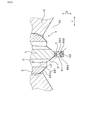
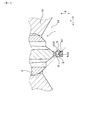
- the spark plug 1 is screwed into a female screw hole 11 provided in the engine head 15 at a mounting screw portion 21. Thus, the spark plug 1 is fastened and fixed to the engine head 15. Furthermore, the tip portion of the spark plug 1 is disposed in the combustion chamber 16. At this time, the spark plug 1 is disposed in a posture in which the air flow in the combustion chamber flows in the lateral direction Y with respect to the tip end portion.
- the air flow F flows along the surface of the engine head 15. Specifically, near the upstream side of the front end portion of the spark plug 1, the air flow F flows in the substantially lateral direction Y toward the front end portion of the spark plug 1.
- the air flow F flowing in the substantially lateral direction Y with respect to the tip portion of the spark plug 1 is changed along the insulator inclined surface 311 of the insulator 3 to the oblique tip side, and the extension of the insulator inclined surface 311 Toward the gap forming surface 521 of the ground electrode 5 on the line. Thereafter, the air flow F blows the discharge gap G obliquely toward the tip end side.
- the direction of the air flow F is changed by the insulator inclined surface 311 of the insulator 3 close to the discharge gap G. Therefore, the air flow F flowing through the discharge gap G flows at an angle close to the plug axial direction Z.
- the insulator protruding portion 31 of the insulator 3 protrudes on the tip end side of the housing 2. Therefore, carbon is less likely to be deposited on the surface of the insulator protruding portion 31 of the insulator 3. Therefore, it is possible to suppress the occurrence of side sparks.
- the outer peripheral surface of the forceps protrusion 31 is a straight or convexly curved forceps inclined surface 311 toward the inner periphery toward the tip side in the plug axial direction Z in the axis parallel cross section.
- an imaginary straight line L1 passing through both ends of the insulator inclined surface 311 is formed to pass through the gap forming surface 521 of the ground electrode 5. Therefore, as shown in FIG. 5, the air flow F in the combustion chamber 16 flows along the insulator inclined surface 311 and is guided to blow through the discharge gap G. Therefore, the air flow F can appropriately flow in the discharge gap G. Therefore, as shown in FIG. 6, it is easy to stretch the discharge sparks S and to improve the ignitability to the air-fuel mixture in the combustion chamber 16.
- the air flow F in the combustion chamber 16 is guided by the insulator inclined surface 311 so as to flow obliquely toward the tip end side of the discharge gap G. Therefore, as shown in FIG. 6, the discharge sparks S are stretched by the air flow toward the oblique tip side, that is, toward the central side of the combustion chamber 16. In other words, the discharge sparks S are stretched away from the engine head 15. Therefore, it is easy to suppress the heat of the flame generated by the ignition from the discharge spark S to the mixture by the engine head 15, and it is easy to grow the flame.
- the insulator inclined surface 311 formed on the insulator 3 located closer to the discharge gap G than the housing 2 Guide the direction of travel. Therefore, the air flow F can be made to flow toward the discharge gap G at an angle close to the plug axial direction Z. Therefore, as shown in FIG. 6, it is easy to stretch the discharge sparks S toward the tip end side, and it is easy to further improve the ignitability.
- the outer peripheral surface of the forceps protrusion part 31 has the forceps inclined surface 311 in the perimeter. Therefore, even if the air flow F flows into the tip portion of the spark plug 1 from any of the lateral directions Y, the air flow F can be guided to the discharge gap G by the insulator inclined surface 311. In addition, the shape of the forceps projecting portion 31 can be easily simplified.
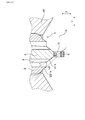
- Second Embodiment is an embodiment in which the shape of the housing 2 is changed with respect to the first embodiment as shown in FIGS. 7 and 8.
- the housing 2 has a housing exposure portion 221 exposed to the combustion chamber 16.
- the outer peripheral surface of the housing exposed portion 221 has a housing inclined surface 221 a that is inclined toward the inner peripheral side toward the distal end side in the plug axial direction Z.
- the housing-side imaginary straight line L2 passing through the both ends of the housing inclined surface 221 a passes through the gap forming surface 521.
- the housing inclined surface 221 a is formed in a linear shape so as to be directed to the inner peripheral side as it goes to the tip end side in the axis parallel cross section.
- the outer peripheral surface of the housing exposed portion 221 has a housing inclined surface 221 a at least in an axial parallel cross section orthogonal to both the plug axial direction Z and the lateral direction Y.
- the outer peripheral surface of the housing exposed portion 221 has a housing inclined surface 221 a on the entire periphery thereof. That is, the outer peripheral surface of the housing exposed portion 221 has a housing inclined surface 221 a in any cross section passing through the plug central axis and parallel to the plug axial direction Z.
- the housing inclined surface 221a is formed such that the dimension in the plug axial direction Z is larger than the dimension in the plug radial direction in the axial parallel cross section.
- the housing inclined surface 221 a is formed to be continuous with the inner peripheral surface of the housing 2.
- the housing-side imaginary straight line L2 passing through both ends of the housing inclined surface 221 a passes through the gap forming surface 521 of the ground electrode 5.
- the housing-side imaginary straight line L2 passes through the region on the gap forming surface 521 opposite to the housing inclined surface 221a in the lateral direction Y.
- the ground electrode 5 is joined to the housing inclined surface 221a.
- the ground connection portion 511 of the ground electrode 5 is formed in parallel with the housing inclined surface 221a.
- the air flow can be guided to the discharge gap G also by the housing inclined surface 221 a of the housing 2 in addition to the insulator inclined surface 311 of the insulator protruding portion 31. Therefore, it is easier to stretch the discharge sparks. In addition, it has the same operation effect as Embodiment 1.
- This embodiment is an embodiment in which the shape of the ground electrode 5 is changed with respect to the second embodiment as shown in FIGS.
- a gap forming surface 521 which is a surface on the base end side of the inward portion 52 has a flat surface 523 orthogonal to the plug axial direction Z and a pair of the flat surfaces 523 formed on both sides in the lateral direction Y.
- a ground inclined surface 522 is a surface facing the opposite side to the insulator inclined surface 311.
- the ground inclined surface 522 is located on the imaginary straight line L1.
- the ground inclined surface 522 is parallel to the insulator inclined surface 311 in the axial parallel cross section.
- the ground inclined surface 522 is formed on substantially the entire inward portion 52 in the longitudinal direction X.
- the air flow F that has passed through the discharge gap G flows along the ground inclined surface 522.
- the air flow F that has passed through the discharge gap G flows in parallel with the ground inclined surface 522, that is, toward the oblique tip side.
- a spark discharge is generated in the discharge gap G by applying a predetermined voltage between the center electrode 4 and the ground electrode 5.
- the initial discharge spark S tends to occur at the edge of the flat surface 523 of the gap forming surface 521 of the ground electrode 5. This is because the flat surface 523 is close to the tip surface 421 of the center electrode tip 42 and the edge of the flat surface 523 is likely to concentrate the electric field around it.
- the initial discharge spark S is stretched downstream as shown in FIG. 13 and FIG. 14 by the airflow of the air-fuel mixture.
- the air flow of the air-fuel mixture that has passed through the discharge gap G flows along the ground inclined surface 522 toward the oblique tip side. Therefore, the discharge sparks S are stretched not only in the lateral direction Y but also toward the tip side.
- the ground side starting point S1 the starting point on the ground electrode 5 side of the discharge sparks S (hereinafter referred to as the ground side starting point S1) is pushed by the air flow and from the edge of the flat surface 523 It moves diagonally to the tip side so as to cover the contact inclined surface 522. Then, along with the movement of the ground side start point S1, the discharge spark S enlarges the linear distance between both start points, and the portion between the both start points is largely stretched to the downstream side, that is, the oblique tip side. And, while being stretched, the air-fuel mixture is ignited by the discharge spark S. Others are the same as in the second embodiment.
- the ground electrode 5 has a ground inclined surface 522 facing the opposite side to the insulator inclined surface 311. Therefore, the air flow F that has passed through the discharge gap G is guided by the ground inclined surface 522 toward the diagonal tip. This makes it easier to stretch the discharge sparks S to the tip side.
- the ground side starting point S1 of the discharge spark S moves, and the linear distance between both start points of the discharge spark S is enlarged.
- the linear distance between both starting points of the discharge spark S large, it is easy to prevent a short circuit between a part of the drawn discharge spark S and another part, and it is easy to greatly stretch the discharge spark S .
- the insulator inclined surface 311 is formed to be linear in the axis parallel cross section, and the ground inclined surface 522 is parallel to the insulator inclined surface 311 in the axis parallel cross section. Therefore, it is easy to smooth the air flow F which blows the discharge gap G obliquely to the tip end side by both the insulator inclined surface 311 and the ground inclined surface 522. In addition, the same effects as those of the second embodiment are obtained.
- the housing inclined surface 221a, the insulator inclined surface 311, and the ground inclined surface 522 are arranged on the same straight line in an axis parallel cross section parallel to the plug axial direction Z and the horizontal direction Y. Embodiment.
- the surface of the forceps protrusion portion 31 has a forceps protruding side surface 312, a forceps inclined surface 311, and a forceps tip end surface 313, which will be described later.
- the forceps projecting side surface 312 is slightly inclined so as to be more inward toward the tip end. In the axial parallel cross section, the straight lines passing through the both ends of the insulator protruding side surface 312 do not pass through the gap forming surface 521 of the ground electrode 5.
- a forceps inclined surface 311 which is inclined more than the forceps protruding side surface 312 is formed.
- the imaginary straight line L1 passing through both ends of the insulator inclined surface 311 passes through the gap forming surface 521 of the ground electrode 5.
- a forceps tip end surface 313 is formed in parallel to the plug axial direction Z on the inner peripheral side from the tip end of the forceps inclined surface 311.
- the imaginary straight line L1 passing through both ends of the insulator inclined surface 311 and the housing side imaginary straight line L2 are the same straight line. Others are the same as in the third embodiment.
- the housing inclined surface 221a, the forceps inclined surface 311, and the ground inclined surface 522 are arranged on the same straight line in an axial parallel cross section parallel to the plug axial direction Z and the lateral direction Y. It is easy to direct the air flow F to the discharge gap G. In addition, the same effects as those of the third embodiment are obtained.
- Embodiment 5 is an embodiment in which the positions where the forceps inclined surface 311, the housing inclined surface 221a, and the ground inclined surface 522 are formed are changed as compared with the fourth embodiment as shown in FIGS.
- the insulator inclined surface 311 and the housing inclined surface 221 a are formed only on the upstream side of the air flow F in the lateral direction Y with respect to the discharge gap G.
- the forceps inclined surface 311 is formed in a range of approximately 120 ° of the forceps projecting portion 31.
- the housing inclined surface 221 a is formed in a range of about 120 ° of the housing exposed portion 221.
- the insulator inclined surface 311 and the housing inclined surface 221a are formed at positions overlapping in the plug radial direction.
- the ground inclined surface 522 is formed only on the downstream side of the air flow F in the lateral direction Y than the discharge gap G. Others are the same as in the fourth embodiment.
- Embodiment 6 This embodiment is an embodiment in which the shape of the center electrode 4 is changed with respect to the fourth embodiment as shown in FIG.
- the center electrode 4 does not have a center electrode tip (see reference numeral 42 in the first to fifth embodiments).
- the outer peripheral surface 411a of the center electrode protrusion 411 which protrudes to the tip side more than the forceps protrusion 31 in the center electrode 4 is formed in a straight line inclined toward the inner periphery toward the tip side in the axis parallel cross section There is.
- the housing inclined surface 221a, the insulator inclined surface 311, the outer peripheral surface 411a of the center electrode protrusion 411 and the ground inclined surface 522 are colinear.
- the shape of the insulator inclined surface 311 is the same as that of the third embodiment. Others are the same as in the fourth embodiment.
- the housing inclined surface 221a, the insulator inclined surface 311, the outer peripheral surface 411a of the center electrode protrusion 411 and the ground inclined surface 522 are on the same straight line
- the air flow is more likely to be directed to the discharge gap G.
- the same effects as those of the fourth embodiment are obtained.
- the present disclosure has been described in accordance with the embodiment, it is understood that the present disclosure is not limited to the embodiment or the structure.
- the present disclosure also includes various modifications and variations within the equivalent range.
- various combinations and forms, and further, other combinations and forms including only one element, more than one element, or less than these elements are also included in the scope and the scope of the present disclosure.
- the insulator inclined surface 311 can also be formed in a curved shape convex toward the inner peripheral side in the axis parallel cross section.
- the housing inclined surface 221a can be formed in a curved shape convex toward the inner peripheral side.
Landscapes
- Spark Plugs (AREA)
Priority Applications (2)
| Application Number | Priority Date | Filing Date | Title |
|---|---|---|---|
| DE112018006646.0T DE112018006646T5 (de) | 2017-12-28 | 2018-12-24 | Zündkerze für Verbrennungsmotoren |
| US16/912,751 US10951011B2 (en) | 2017-12-28 | 2020-06-26 | Spark plug for internal combustion engines |
Applications Claiming Priority (2)
| Application Number | Priority Date | Filing Date | Title |
|---|---|---|---|
| JP2017253620A JP7118640B2 (ja) | 2017-12-28 | 2017-12-28 | 内燃機関用のスパークプラグ |
| JP2017-253620 | 2017-12-28 |
Related Child Applications (1)
| Application Number | Title | Priority Date | Filing Date |
|---|---|---|---|
| US16/912,751 Continuation US10951011B2 (en) | 2017-12-28 | 2020-06-26 | Spark plug for internal combustion engines |
Publications (1)
| Publication Number | Publication Date |
|---|---|
| WO2019131565A1 true WO2019131565A1 (ja) | 2019-07-04 |
Family
ID=67067242
Family Applications (1)
| Application Number | Title | Priority Date | Filing Date |
|---|---|---|---|
| PCT/JP2018/047406 Ceased WO2019131565A1 (ja) | 2017-12-28 | 2018-12-24 | 内燃機関用のスパークプラグ |
Country Status (4)
| Country | Link |
|---|---|
| US (1) | US10951011B2 (enExample) |
| JP (1) | JP7118640B2 (enExample) |
| DE (1) | DE112018006646T5 (enExample) |
| WO (1) | WO2019131565A1 (enExample) |
Citations (4)
| Publication number | Priority date | Publication date | Assignee | Title |
|---|---|---|---|---|
| JPH09129356A (ja) * | 1995-11-02 | 1997-05-16 | Ngk Spark Plug Co Ltd | 内燃機関用スパークプラグ |
| JP2008108479A (ja) * | 2006-10-24 | 2008-05-08 | Denso Corp | 内燃機関用スパークプラグ |
| JP2013513928A (ja) * | 2009-12-15 | 2013-04-22 | フェデラル−モーグル・イグニション・カンパニー | 内燃機関のためのスパーク点火装置およびそのための中心電極アセンブリ |
| WO2016013615A1 (ja) * | 2014-07-24 | 2016-01-28 | イマジニアリング株式会社 | 点火プラグ |
Family Cites Families (2)
| Publication number | Priority date | Publication date | Assignee | Title |
|---|---|---|---|---|
| JP5208033B2 (ja) | 2009-03-30 | 2013-06-12 | 株式会社日本自動車部品総合研究所 | スパークプラグ |
| JP5719419B2 (ja) * | 2013-01-31 | 2015-05-20 | 日本特殊陶業株式会社 | 点火プラグ及びその製造方法 |
-
2017
- 2017-12-28 JP JP2017253620A patent/JP7118640B2/ja active Active
-
2018
- 2018-12-24 WO PCT/JP2018/047406 patent/WO2019131565A1/ja not_active Ceased
- 2018-12-24 DE DE112018006646.0T patent/DE112018006646T5/de active Pending
-
2020
- 2020-06-26 US US16/912,751 patent/US10951011B2/en active Active
Patent Citations (4)
| Publication number | Priority date | Publication date | Assignee | Title |
|---|---|---|---|---|
| JPH09129356A (ja) * | 1995-11-02 | 1997-05-16 | Ngk Spark Plug Co Ltd | 内燃機関用スパークプラグ |
| JP2008108479A (ja) * | 2006-10-24 | 2008-05-08 | Denso Corp | 内燃機関用スパークプラグ |
| JP2013513928A (ja) * | 2009-12-15 | 2013-04-22 | フェデラル−モーグル・イグニション・カンパニー | 内燃機関のためのスパーク点火装置およびそのための中心電極アセンブリ |
| WO2016013615A1 (ja) * | 2014-07-24 | 2016-01-28 | イマジニアリング株式会社 | 点火プラグ |
Also Published As
| Publication number | Publication date |
|---|---|
| DE112018006646T5 (de) | 2020-09-10 |
| JP2019121446A (ja) | 2019-07-22 |
| JP7118640B2 (ja) | 2022-08-16 |
| US10951011B2 (en) | 2021-03-16 |
| US20200335950A1 (en) | 2020-10-22 |
Similar Documents
| Publication | Publication Date | Title |
|---|---|---|
| JP2017079171A (ja) | 内燃機関用のスパークプラグ及びそれを取り付けた点火装置 | |
| US10454252B2 (en) | Spark plug for internal combustion engine | |
| JP6041824B2 (ja) | スパークプラグ、および、点火システム | |
| JP2008311185A (ja) | 内燃機関用のスパークプラグ | |
| JP6680043B2 (ja) | 内燃機関用のスパークプラグ | |
| WO2019131565A1 (ja) | 内燃機関用のスパークプラグ | |
| US11973323B2 (en) | Spark plug for internal combustion engine | |
| JP6731298B2 (ja) | 内燃機関用のスパークプラグ | |
| WO2016021445A1 (ja) | 内燃機関用のスパークプラグ | |
| JP2020061261A (ja) | スパークプラグ | |
| US10777974B2 (en) | Spark plug for internal combustion engine that makes re-discharge less prone to occur | |
| US10333282B2 (en) | Spark plug for internal combustion engine | |
| US9377001B2 (en) | Spark plug for internal combustion engine | |
| JP7122860B2 (ja) | 内燃機関用のスパークプラグ | |
| JP7194550B2 (ja) | 内燃機関用のスパークプラグ | |
| US9234491B2 (en) | Spark plug for internal combustion engine | |
| JP6836907B2 (ja) | 内燃機関用のスパークプラグ | |
| WO2019138854A1 (ja) | 内燃機関用の点火プラグ及び内燃機関 | |
| JP2019046742A (ja) | 内燃機関用のスパークプラグ | |
| US10886709B1 (en) | Spark plug that prevents gas turbulence in the discharge space | |
| JP6295824B2 (ja) | 内燃機関用のスパークプラグ及びその製造方法 | |
| JP2017174758A (ja) | 内燃機関用のスパークプラグ | |
| JP2014229557A (ja) | 点火プラグ |
Legal Events
| Date | Code | Title | Description |
|---|---|---|---|
| 121 | Ep: the epo has been informed by wipo that ep was designated in this application |
Ref document number: 18893689 Country of ref document: EP Kind code of ref document: A1 |
|
| 122 | Ep: pct application non-entry in european phase |
Ref document number: 18893689 Country of ref document: EP Kind code of ref document: A1 |