WO2019117195A1 - ショベル - Google Patents
ショベル Download PDFInfo
- Publication number
- WO2019117195A1 WO2019117195A1 PCT/JP2018/045670 JP2018045670W WO2019117195A1 WO 2019117195 A1 WO2019117195 A1 WO 2019117195A1 JP 2018045670 W JP2018045670 W JP 2018045670W WO 2019117195 A1 WO2019117195 A1 WO 2019117195A1
- Authority
- WO
- WIPO (PCT)
- Prior art keywords
- fuel tank
- rollover valve
- valve
- shovel according
- hose
- Prior art date
Links
Images


Classifications
-
- B—PERFORMING OPERATIONS; TRANSPORTING
- B60—VEHICLES IN GENERAL
- B60K—ARRANGEMENT OR MOUNTING OF PROPULSION UNITS OR OF TRANSMISSIONS IN VEHICLES; ARRANGEMENT OR MOUNTING OF PLURAL DIVERSE PRIME-MOVERS IN VEHICLES; AUXILIARY DRIVES FOR VEHICLES; INSTRUMENTATION OR DASHBOARDS FOR VEHICLES; ARRANGEMENTS IN CONNECTION WITH COOLING, AIR INTAKE, GAS EXHAUST OR FUEL SUPPLY OF PROPULSION UNITS IN VEHICLES
- B60K15/00—Arrangement in connection with fuel supply of combustion engines or other fuel consuming energy converters, e.g. fuel cells; Mounting or construction of fuel tanks
- B60K15/03—Fuel tanks
- B60K15/073—Tank construction specially adapted to the vehicle
-
- E—FIXED CONSTRUCTIONS
- E02—HYDRAULIC ENGINEERING; FOUNDATIONS; SOIL SHIFTING
- E02F—DREDGING; SOIL-SHIFTING
- E02F9/00—Component parts of dredgers or soil-shifting machines, not restricted to one of the kinds covered by groups E02F3/00 - E02F7/00
- E02F9/08—Superstructures; Supports for superstructures
- E02F9/0833—Improving access, e.g. for maintenance, steps for improving driver's access, handrails
-
- B—PERFORMING OPERATIONS; TRANSPORTING
- B60—VEHICLES IN GENERAL
- B60K—ARRANGEMENT OR MOUNTING OF PROPULSION UNITS OR OF TRANSMISSIONS IN VEHICLES; ARRANGEMENT OR MOUNTING OF PLURAL DIVERSE PRIME-MOVERS IN VEHICLES; AUXILIARY DRIVES FOR VEHICLES; INSTRUMENTATION OR DASHBOARDS FOR VEHICLES; ARRANGEMENTS IN CONNECTION WITH COOLING, AIR INTAKE, GAS EXHAUST OR FUEL SUPPLY OF PROPULSION UNITS IN VEHICLES
- B60K15/00—Arrangement in connection with fuel supply of combustion engines or other fuel consuming energy converters, e.g. fuel cells; Mounting or construction of fuel tanks
- B60K15/03—Fuel tanks
- B60K15/035—Fuel tanks characterised by venting means
- B60K15/03504—Fuel tanks characterised by venting means adapted to avoid loss of fuel or fuel vapour, e.g. with vapour recovery systems
-
- B—PERFORMING OPERATIONS; TRANSPORTING
- B60—VEHICLES IN GENERAL
- B60K—ARRANGEMENT OR MOUNTING OF PROPULSION UNITS OR OF TRANSMISSIONS IN VEHICLES; ARRANGEMENT OR MOUNTING OF PLURAL DIVERSE PRIME-MOVERS IN VEHICLES; AUXILIARY DRIVES FOR VEHICLES; INSTRUMENTATION OR DASHBOARDS FOR VEHICLES; ARRANGEMENTS IN CONNECTION WITH COOLING, AIR INTAKE, GAS EXHAUST OR FUEL SUPPLY OF PROPULSION UNITS IN VEHICLES
- B60K15/00—Arrangement in connection with fuel supply of combustion engines or other fuel consuming energy converters, e.g. fuel cells; Mounting or construction of fuel tanks
- B60K15/03—Fuel tanks
- B60K15/063—Arrangement of tanks
- B60K15/067—Mounting of tanks
-
- E—FIXED CONSTRUCTIONS
- E02—HYDRAULIC ENGINEERING; FOUNDATIONS; SOIL SHIFTING
- E02F—DREDGING; SOIL-SHIFTING
- E02F9/00—Component parts of dredgers or soil-shifting machines, not restricted to one of the kinds covered by groups E02F3/00 - E02F7/00
- E02F9/08—Superstructures; Supports for superstructures
- E02F9/0858—Arrangement of component parts installed on superstructures not otherwise provided for, e.g. electric components, fenders, air-conditioning units
- E02F9/0875—Arrangement of valve arrangements on superstructures
-
- E—FIXED CONSTRUCTIONS
- E02—HYDRAULIC ENGINEERING; FOUNDATIONS; SOIL SHIFTING
- E02F—DREDGING; SOIL-SHIFTING
- E02F9/00—Component parts of dredgers or soil-shifting machines, not restricted to one of the kinds covered by groups E02F3/00 - E02F7/00
- E02F9/08—Superstructures; Supports for superstructures
- E02F9/0858—Arrangement of component parts installed on superstructures not otherwise provided for, e.g. electric components, fenders, air-conditioning units
- E02F9/0883—Tanks, e.g. oil tank, urea tank, fuel tank
-
- E—FIXED CONSTRUCTIONS
- E02—HYDRAULIC ENGINEERING; FOUNDATIONS; SOIL SHIFTING
- E02F—DREDGING; SOIL-SHIFTING
- E02F9/00—Component parts of dredgers or soil-shifting machines, not restricted to one of the kinds covered by groups E02F3/00 - E02F7/00
- E02F9/24—Safety devices, e.g. for preventing overload
-
- B—PERFORMING OPERATIONS; TRANSPORTING
- B60—VEHICLES IN GENERAL
- B60K—ARRANGEMENT OR MOUNTING OF PROPULSION UNITS OR OF TRANSMISSIONS IN VEHICLES; ARRANGEMENT OR MOUNTING OF PLURAL DIVERSE PRIME-MOVERS IN VEHICLES; AUXILIARY DRIVES FOR VEHICLES; INSTRUMENTATION OR DASHBOARDS FOR VEHICLES; ARRANGEMENTS IN CONNECTION WITH COOLING, AIR INTAKE, GAS EXHAUST OR FUEL SUPPLY OF PROPULSION UNITS IN VEHICLES
- B60K15/00—Arrangement in connection with fuel supply of combustion engines or other fuel consuming energy converters, e.g. fuel cells; Mounting or construction of fuel tanks
- B60K15/03—Fuel tanks
- B60K15/035—Fuel tanks characterised by venting means
- B60K2015/03523—Arrangements of the venting tube
-
- B—PERFORMING OPERATIONS; TRANSPORTING
- B60—VEHICLES IN GENERAL
- B60K—ARRANGEMENT OR MOUNTING OF PROPULSION UNITS OR OF TRANSMISSIONS IN VEHICLES; ARRANGEMENT OR MOUNTING OF PLURAL DIVERSE PRIME-MOVERS IN VEHICLES; AUXILIARY DRIVES FOR VEHICLES; INSTRUMENTATION OR DASHBOARDS FOR VEHICLES; ARRANGEMENTS IN CONNECTION WITH COOLING, AIR INTAKE, GAS EXHAUST OR FUEL SUPPLY OF PROPULSION UNITS IN VEHICLES
- B60K15/00—Arrangement in connection with fuel supply of combustion engines or other fuel consuming energy converters, e.g. fuel cells; Mounting or construction of fuel tanks
- B60K15/03—Fuel tanks
- B60K15/035—Fuel tanks characterised by venting means
- B60K2015/03542—Mounting of the venting means
- B60K2015/03552—Mounting of the venting means the venting means are integrated into the fuel filler pipe
-
- B—PERFORMING OPERATIONS; TRANSPORTING
- B60—VEHICLES IN GENERAL
- B60K—ARRANGEMENT OR MOUNTING OF PROPULSION UNITS OR OF TRANSMISSIONS IN VEHICLES; ARRANGEMENT OR MOUNTING OF PLURAL DIVERSE PRIME-MOVERS IN VEHICLES; AUXILIARY DRIVES FOR VEHICLES; INSTRUMENTATION OR DASHBOARDS FOR VEHICLES; ARRANGEMENTS IN CONNECTION WITH COOLING, AIR INTAKE, GAS EXHAUST OR FUEL SUPPLY OF PROPULSION UNITS IN VEHICLES
- B60K15/00—Arrangement in connection with fuel supply of combustion engines or other fuel consuming energy converters, e.g. fuel cells; Mounting or construction of fuel tanks
- B60K15/03—Fuel tanks
- B60K15/035—Fuel tanks characterised by venting means
- B60K2015/03542—Mounting of the venting means
- B60K2015/03557—Mounting of the venting means comprising elements of the venting device integrated in the fuel tank, e.g. vapor recovery means
-
- B—PERFORMING OPERATIONS; TRANSPORTING
- B60—VEHICLES IN GENERAL
- B60K—ARRANGEMENT OR MOUNTING OF PROPULSION UNITS OR OF TRANSMISSIONS IN VEHICLES; ARRANGEMENT OR MOUNTING OF PLURAL DIVERSE PRIME-MOVERS IN VEHICLES; AUXILIARY DRIVES FOR VEHICLES; INSTRUMENTATION OR DASHBOARDS FOR VEHICLES; ARRANGEMENTS IN CONNECTION WITH COOLING, AIR INTAKE, GAS EXHAUST OR FUEL SUPPLY OF PROPULSION UNITS IN VEHICLES
- B60K15/00—Arrangement in connection with fuel supply of combustion engines or other fuel consuming energy converters, e.g. fuel cells; Mounting or construction of fuel tanks
- B60K15/03—Fuel tanks
- B60K15/035—Fuel tanks characterised by venting means
- B60K2015/03561—Venting means working at specific times
- B60K2015/03576—Venting during filling the reservoir
-
- B—PERFORMING OPERATIONS; TRANSPORTING
- B60—VEHICLES IN GENERAL
- B60K—ARRANGEMENT OR MOUNTING OF PROPULSION UNITS OR OF TRANSMISSIONS IN VEHICLES; ARRANGEMENT OR MOUNTING OF PLURAL DIVERSE PRIME-MOVERS IN VEHICLES; AUXILIARY DRIVES FOR VEHICLES; INSTRUMENTATION OR DASHBOARDS FOR VEHICLES; ARRANGEMENTS IN CONNECTION WITH COOLING, AIR INTAKE, GAS EXHAUST OR FUEL SUPPLY OF PROPULSION UNITS IN VEHICLES
- B60K15/00—Arrangement in connection with fuel supply of combustion engines or other fuel consuming energy converters, e.g. fuel cells; Mounting or construction of fuel tanks
- B60K15/03—Fuel tanks
- B60K15/063—Arrangement of tanks
- B60K2015/0636—Arrangement of tanks the fuel tank being part of the chassis or frame
-
- E—FIXED CONSTRUCTIONS
- E02—HYDRAULIC ENGINEERING; FOUNDATIONS; SOIL SHIFTING
- E02F—DREDGING; SOIL-SHIFTING
- E02F3/00—Dredgers; Soil-shifting machines
- E02F3/04—Dredgers; Soil-shifting machines mechanically-driven
- E02F3/28—Dredgers; Soil-shifting machines mechanically-driven with digging tools mounted on a dipper- or bucket-arm, i.e. there is either one arm or a pair of arms, e.g. dippers, buckets
- E02F3/30—Dredgers; Soil-shifting machines mechanically-driven with digging tools mounted on a dipper- or bucket-arm, i.e. there is either one arm or a pair of arms, e.g. dippers, buckets with a dipper-arm pivoted on a cantilever beam, i.e. boom
- E02F3/32—Dredgers; Soil-shifting machines mechanically-driven with digging tools mounted on a dipper- or bucket-arm, i.e. there is either one arm or a pair of arms, e.g. dippers, buckets with a dipper-arm pivoted on a cantilever beam, i.e. boom working downwardly and towards the machine, e.g. with backhoes
Definitions
- the present disclosure relates to a shovel.
- the cap of the filler port is provided with an air vent function to the outside, and air is introduced inside the tank via the air vent function according to the fuel in the fuel tank being supplied to the engine (For example, patent document 1).
- the cap of the fuel supply port has a ventilation function, there is a possibility that the fuel inside the fuel tank may leak to the outside through the ventilation function when the shovel falls over.
- the present disclosure aims to provide a shovel capable of preventing fuel leakage from a fuel tank at the time of tipping.
- the shovel includes a lower traveling body, an upper revolving body pivotally attached to the lower traveling body, a boom pivotally attached to the upper revolving body, and a pivotable to the boom Provided on an upper surface of the fuel tank, an engine mounted on the upper swing body, a hydraulic pump mounted on the upper swing body, a fuel tank mounted on the upper swing body, And a roll over valve provided at an upper portion of the fuel tank and provided at a position different from the work passage.
- the X direction, the Y direction, and the Z direction are directions perpendicular to one another, the X direction and the Y direction are horizontal directions, and the Z direction is a vertical direction.
- the X direction is the front-rear direction of the shovel 100, the front side is the X positive direction, and the rear side is the X negative direction.
- the Y direction is the lateral width direction of the shovel 100, the left side is the Y positive direction, and the right side is the Y negative direction.
- the Z direction is the height direction of the shovel 100, and the upper side is the Z positive direction, and the lower side is the Z negative direction.
- FIG. 1 is a side view of a shovel 100 according to an embodiment of the present invention.
- the shovel 100 has a lower traveling body 1, an upper swing body 2, a cabin 3, a boom 4, an arm 5, and a bucket 6.
- the upper revolving superstructure 2 is mounted on the lower traveling vehicle 1 via a pivoting mechanism (not shown).
- a cabin 3 provided with a driver's seat inside is disposed at the left front of the upper swing body 2.
- One end of the boom 4 is rotatably mounted at the front center of the upper swing body 2.
- the arm 5 is rotatably attached to the tip of the boom 4.
- the bucket 6 which is an end attachment is rotatably attached to the tip of the arm 5.
- an end attachment such as a breaker or a crusher may be attached to the tip of the arm 5.
- a guardrail is attached to the upper swing body 2 in order to be grasped when the operator climbs the upper swing body 2 or to prevent a worker working on the upper swing body 2 from falling.
- FIG. 2 is a plan view of the upper swing body 2.
- FIG. 3 is an enlarged perspective view of the vicinity of the fuel tank 19F of the upper revolving superstructure 2. As shown in FIG. In addition, in FIG. 2, the state from which the boom 4 was removed is shown for convenience of illustration.
- an air cleaner chamber 8 is formed at the rear of the cabin 3.
- An air cleaner or the like is accommodated in the air cleaner chamber 8. Further, the upper portion of the air cleaner chamber 8 is covered with a top plate 8a.
- a radiator chamber 9 is formed behind the air cleaner chamber 8.
- a battery, a radiator and the like are accommodated in the radiator chamber 9.
- a counterweight is disposed behind the radiator chamber 9.
- the catwalk 20 ⁇ / b> L is arranged to extend in the front-rear direction along the left end of the upper swing body 2.
- the catwalk 20L is disposed to extend in the front-rear direction along the swing frame 2a at the left end of the upper swing body 2 and is removably attached to the swing frame 2a.
- the guard rail G1 is a member that prevents a worker who works on the upper swing body 2 from falling.
- the guard rail G1 is fixed to the top plate 8a above the air cleaner chamber 8 by bolting.
- the guard rail G1 may be welded to the top plate 8a.
- the stays CS1 and CS2 are arranged to extend parallel and horizontally in the front-rear direction corresponding to the catwalk 20L. Further, the heights of the stays CS1 and CS2 with respect to the catwalk 20L are arranged within a predetermined range.
- the predetermined range is, for example, 1000 to 1300 mm.
- the stay CS1 is welded to the outer frame member G10 of the guard rail G1. And as shown in FIG. 2, stay CS1 is attached so that it may protrude on the left outer side (catwalk 20L side) with respect to the outer frame member G10 of the guard rail G1. Further, the stay CS2 is fixed by bolting.
- a pump chamber 7 is formed behind the upper swing body 2.
- the pump chamber 7 accommodates the engine 11 and the hydraulic pump 14 and the like.
- An upper portion of the pump chamber 7 and the radiator chamber 9 is covered with an engine hood 7a.
- the operator can stand on the top cover 2b disposed adjacent to the top plate 8a as shown in FIG. 2 and pull up the handle 7a3 in front of the engine hood 7a to open the engine hood 7a.
- the handle 7a3 is pulled up, the engine hood 7a is opened with the hinges 7a1 and 7a2 as pivot axes.
- a hydraulic fluid tank 19S storing hydraulic fluid discharged by the hydraulic pump 14 and a fuel tank 19F storing fuel supplied to the engine 11 are disposed.
- Top plates 7b and 7c are installed on the hydraulic oil tank 19S and the fuel tank 19F. This is to allow the worker to work on the top plates 7 b and 7 c.
- Catwalk 20 ⁇ / b> R is arranged to extend in the front-rear direction along the right end of upper revolving unit 2.
- the catwalk 20R is disposed to extend in the front-rear direction along the swing frame 2a at the right end of the upper swing body 2 and is removably attached to the swing frame 2a.
- the guard rails G ⁇ b> 2 and G ⁇ b> 3 are members for preventing a worker working on the upper swing body 2 from falling.
- the guard rail G2 is bolted and fixed to the top plate 7c above the fuel tank 19F.
- the guard rail G3 is bolted to the top plate 7b above the hydraulic oil tank 19S.
- the guard rails G2 and G3 may be welded to the top plates 7b and 7c.
- the guard rail G2 contains the outer frame member G20 and the horizontal member G22, and the both ends of the outer frame member G20 are fixed to the top plate 7c. Then, the inside of the outer frame member G20 is partitioned by the lateral member G22.
- the guard rail G3 includes an outer frame member G30 and a lateral member G32, and both ends of the outer frame member G30 are fixed to the top plate 7b. Then, the inside of the outer frame member G30 is partitioned by the lateral member G32.
- the stays CS3 to CS6 are arranged to extend horizontally in parallel with the catwalk 20R in the front-rear direction. Further, the heights of the stays CS3 to CS6 with respect to the catwalk 20R are arranged to be within a predetermined range.
- the predetermined range is, for example, 1000 to 1300 mm.
- the stay CS3 is welded to the outer frame member G20 of the guard rail G2.
- the stay CS3 is attached so as to protrude outward to the right (catwalk 20R side) with respect to the outer frame member G20 of the guard rail G2 and the fuel supply port 19Fa.
- the stay CS4 is welded to the outer frame member G30 of the guard rail G3.
- the stay CS4 is attached to the outer frame member G30 of the guard rail G3 so as to protrude outward to the right (the catwalk 20R side).
- the stay CS5 is bolted to a house frame (not shown) in the pump chamber 7.
- a processing agent tank 19R Disposed in front of the fuel tank 19F is a processing agent tank 19R in which a processing agent (eg, urea water as a reducing agent) for processing the exhaust gas of the engine 11 is stored. Further, the upper surface of the processing agent tank 19R is covered with the processing agent tank cover 40 when the processing agent tank cover is closed, and the upper surface is exposed when the processing agent tank cover 40 is opened. Further, the top surface of the processing agent tank cover 40 is partially lowered as shown in FIG. 3 and a step is provided. This step forms a staircase that is used when the operator climbs the upper swing body 2.
- a processing agent eg, urea water as a reducing agent
- a tool box 22 having a space capable of storing a working tool or the like is installed.
- the upper surface of the tool box 22 is also used as part of the stairs used when the operator climbs on the upper swing body 2.
- a step 23 is provided as a footrest used as a part of the stairs used when the operator climbs the upper swing body 2. Step 23 is attached to the pivot frame 2a in front of the portion where the tool case 22 is installed.
- a handrail unit 50 is attached as a guard rail G4 in the vicinity of the stairs formed in this manner.
- the handrail unit 50 is disposed in the upper revolving unit 2 on the front right side opposite to the cabin 3 disposed on the front left side.
- a boom support bracket 4 a that pivotally supports the boom 4 is fixed to the front center of the upper swing body 2. Therefore, the above-described stairs are formed between the boom support bracket 4 a and the handrail unit 50.
- the handrail unit 50 has a handrail 52 as a first handrail for the operator to hold and support the body.
- the handrail unit 50 also has a handrail 54 as a second handrail that extends horizontally below the handrail 52.
- the handrail 54 not only functions as a stay CS6 which is a handrail when the operator moves on the catwalk 20R, but also functions as a reinforcing member for reinforcing the handrail unit 50 (handrail 52).
- the front end (lower side) of the handrail unit 50 is fixed to the front end face of the revolving frame 2a, and the rear end (high side) is fixed to the upper surface of the top plate 7c on the fuel tank 19F.
- top plate 7c on the fuel tank 19F continuing from the above steps above the guard rail G2 on the machine inner side (the Y positive direction side) and a portion of the top plate 7b above the hydraulic oil tank 19S on the inner side of the guard rail G3
- a passage 70 (see FIG. 5) is formed.
- the outer frame member G20 of the guardrail G2 installed on the top plate 7c of the fuel tank 19F is also expressed as a "handrail portion" for a worker passing through the work passage 70 to grip when moving.
- the fuel supply port 19Fa (liquid supply port) of the fuel tank 19F is disposed on the top plate 7c (upper surface of the tank) so that the outer end is located at the Y-direction position of the handrail portion (outer frame member G20). As a result, it is arranged so as not to interfere with a worker passing through the work passage, and to facilitate refueling from both the work passage 70 side and the catwalk 20R side.
- the fuel supply port 19Fa of the fuel tank 19F is provided at a position other than the work passage 70. That is, in the top plate 7c of the fuel tank 19F, the portion on the inner side of the fuel supply port 19Fa becomes the work passage 70.
- a non-slip sheet may be installed on the top plate 7c of the fuel tank 19F for the safety of workers, the portion of the non-slip sheet may be used as the work passage 70.
- the fuel tank 19F needs to prevent the inside of the tank from being in a vacuum state by introducing air into the tank in response to the fuel supplied to the engine 11.
- the cap of the filler port is generally provided with a ventilation function, but in the present embodiment, the cap of the filler port 19Fa does not have the ventilation function and seals the filler port 19Fa.
- a rollover valve 60 is provided separately from the fuel supply port 19Fa as a ventilation function of the fuel tank 19F.
- the rollover valve 60 is normally open and communicates between the inside and the outside of the tank, but when the fuel enters the tank to full capacity and the oil level is high, or when the fuel tank is inclined due to overturning of the shovel Close the valve.
- the fuel supply port 19Fa of the fuel tank 19F is sealed with a cap, and the rollover valve 60 is provided so that the fuel tank 19F is erected via the rollover valve 60. Air can be conducted between the fuel tank 19F and the outside, and fuel leakage from the fuel supply port 19Fa and the rollover valve 60 can be prevented when the fuel tank 19F rolls over or overturns.
- the rollover valve 60 is provided on the top of the fuel tank 19F and is disposed at a position different from the working passage 70.
- the rollover valve 60 is disposed outside the handrail portion (outer frame member G20) of the top plate 7c of the fuel tank 19F.
- the rollover valve 60 can be reliably separated from the working passage 70, so that the rollover valve 60 can be disposed so as not to disturb the worker passing through the working passage 70.
- the rollover valve 60 away from the work passage 70 it is possible to prevent foreign matter such as earth and sand adhering to the shoe of the worker from adhering to the rollover valve 60. It is possible to reduce the possibility of malfunction (such as a situation in which the tank does not open at the time of erecting the tank).
- the fuel tank 19F has a rollover valve 60, a filler port 19Fa, a hose 66, and a liquid level setting upper limit UL (see FIG. 6).
- the liquid level setting upper limit UL is the liquid level height when the fuel tank 19F has the maximum amount of fuel that can be put therein.
- a level gauge 67 (see FIG. 6) as a fuel gauge is disposed above the side surface of the fuel tank 19F.
- the maximum value of the scale indicated by the level gauge 67 is the liquid level setting upper limit UL. For example, the operator can use this level gauge 67 to refuel the fuel until the liquid level reaches the liquid level setting upper limit UL.
- the rollover valve 60 is disposed above the liquid level setting upper limit UL. This is to perform the function of causing the air to flow out of the rollover valve 60.
- the maximum value of the scale indicated by the level gauge 67 is the liquid level setting upper limit UL
- the position below the maximum value of the scale may be the liquid level setting upper limit UL in consideration of an error or the like.
- the liquid level setting upper limit UL is visually recognized using the level gauge 67, but a float-type fuel remaining amount gauge or a sensor-type fuel remaining amount gauge may be used.
- the tip of the float when the fuel in the fuel tank 19F is full, the tip of the float may be visible at the fuel inlet 19Fa. In this case, the operator can grasp the fueling state of the fuel in the fuel tank 19F by visually observing the position of the tip of the float which is the fuel remaining amount meter while pouring the fuel from the fuel supply port 19Fa.
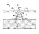
- FIG. 4A, FIG. 4B, and FIG. 4C are schematic diagrams which show an example of the structure of the roll over valve
- the rollover valve 60 includes, for example, a valve body 61, a float 62, a spring 63, and a guide 64.
- the valve body 61 and the float 62 are accommodated in the guide 64 in a state of being connected by a spring.
- the guide 64 is a cylindrical member configured to be able to slide the valve body 61 and the like along the communication direction of the discharge passage 65 provided through the surface of the fuel tank 19F.
- the guide 64 is provided with an opening 64 a on the bottom opposite to the discharge passage 65. Further, a communication hole 64 b is provided on the circumferential surface of the guide 64.
- the guide 64 is disposed immediately below the discharge passage 65. And the opening 64a of the guide 64 is at the bottom.
- the float 62 is disposed below the valve body 61 inside the guide 64.
- the float 62 can not receive buoyancy from the level. For this reason, the float 62 is in contact with the bottom surface of the guide 64, and the spring contracts due to the weight of the valve body 61, and the valve body 61 is separated downward from the discharge passage 65 to be open.
- the communication hole 64b is between the discharge passage 65 and the valve body 61, the discharge passage 65 and the inside of the tank communicate with each other, whereby the inflow of air into the tank and the outflow of air into the outside Is possible.
- the rollover valve 60 is connected to a hose 66 for air conduction. Since the opening of the rollover valve 60 is blocked by the hose 66, adhesion of foreign matter such as earth and sand to the rollover valve 60 can be further suppressed, and the risk of malfunction of the rollover valve 60 due to foreign matter can be further reduced. .
- the hose 66 connected to the rollover valve 60 is routed to the side of the fuel tank 19F. More specifically, the hose 66 hangs downward in the gap between the side surface of the fuel tank 19F and the outer wall (tank lateral cover) 21 of the upper swing body 2. Thus, foreign matter such as earth and sand can be further suppressed from entering the roll over valve 60 through the hose 66.
- the hose 66 is disposed downward in the gap between the side surface of the fuel tank 19F and the outer wall (tank lateral cover) 21 of the upper swing body 2, but the hose 66 is It may be arranged to hang between the fuel tank 19F and the hydraulic oil tank 19S, or arranged to hang along the side (the side in the positive direction of X) of the fuel tank 19F on the processing agent tank 19R side. It is also good.
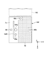
- FIG. 5 is a plan view of a fuel tank 19F showing a modification of the arrangement of the roll over valve 60.
- FIG. 6 is a side view of a fuel tank 19F showing a modification of the arrangement of the roll over valve 60.
- FIG. 5 is a plan view of a fuel tank 19F showing a modification of the arrangement of the roll over valve 60.
- the rollover valve 60 may be provided on the surface of the fuel tank 19F at a position other than the working passage 70.
- the Y-direction position may be the same as the position of the fuel supply port 19Fa, or may be disposed outside the machine body from the fuel supply port 19Fa. Further, it may be disposed at the end of the top plate 7c at the inner side of the machine like the rollover valve 60b shown in FIG. 5 or the hydraulic oil tank 19S side (X negative direction side) as the rollover valve 60c. It may be placed at the end of the In these cases, as shown in FIG. 5 in a satin finish, the top plate 7c on the fuel tank 19F is the work passage 70 except for the portions where the rollover valves 60, 60a, 60b, 60c are installed. .
- the hose 66 is routed to the side surface of the fuel tank 19F.
- the hose 66 is routed downward in the gap between the side surface of the fuel tank 19F and the outer wall 21 (see FIG. 3) of the upper swing body 2.
- the hose 66 is arranged to hang down along the side surface of the fuel tank 19F on the air cleaner chamber 8 side (see FIG. 2).
- the hose 66 is arranged to hang between the fuel tank 19F and the hydraulic oil tank 19S.
- a level gauge 67 is shown in FIG.
- the maximum value of the memory indicated by the level gauge 67 is the liquid level setting upper limit UL.
- the operator can use this level gauge 67 to refuel the fuel until the liquid level reaches the liquid level setting upper limit UL.
- the rollover valve 60d may be provided above the liquid level setting upper limit UL and on the side surface of the fuel tank 19F.
- the roll over valve 60d is disposed above the liquid level setting upper limit UL in order to cause the air to flow out of the roll over valve 60d.
- the liquid level setting upper limit UL is visually recognized using the level gauge 67, but a float-type fuel remaining amount gauge or a sensor-type fuel remaining amount gauge may be used.
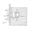
- FIG. 7A is a perspective view of a modification including the protective cover 71 of the rollover valve 60.
- FIG. 7B is a side view of a modification including the protective cover 71 of the rollover valve 60. As shown in FIG.
- the shovel 100 of this embodiment can also be equipped with the protective cover 71 provided above the rollover valve 60.
- the protective cover 71 can protect the rollover valve 60 by preventing the rollover valve 60 from being hit by another object from above or from the side.
- the protective cover 71 is, for example, a box having a rectangular parallelepiped shape as shown in FIG. 7A, and a fuel tank so that the upper wall 71a and the side walls 71b, 71c, 71d cover the upper side and the side of the rollover valve 60. It is provided on the surface of 19F.
- the protective cover 71 is directly fixed to the fuel tank 19F using, for example, bolting or welding.
- the protective cover 71 may cover at least the upper side of the rollover valve 60 so as to protect it.
- the side walls 71b and 71c on both sides in the X direction of the rollover valve 60 may not be provided.
- the protective cover 71 may have an arbitrary shape such as a dome shape having a predetermined curvature or a cylindrical shape, for example.
- the upper wall 71a of the protective cover 71 is parallel to the upper surface of the fuel tank 19F, but the upper wall 71a of the protective cover 71 is a fuel tank You may incline with respect to the upper surface of 19F.
- the protective cover 71 may have a bottom portion.
- one of the side faces of the cubic shape is opened in the protective cover 71, and a hose 66 connected to the side of the rollover valve 60 protrudes from the opening 72.
- the protective cover 71 extends in the protruding direction of the hose 66 and has a collar 73 provided above the hose 66.
- the collar portion 73 forms an inclined surface which is inclined in the negative Z direction while advancing in the negative Y direction from the upper side of the side surface (the opening 72 in FIG. 7A) of the portion where the hose 66 protrudes from the protective cover 71 Provided as.
- the hook portion 73 can prevent the hose 66 from being hit by another object from above or from the side, and the hose 66 can be protected. Further, by providing the flange portion 73, the entry of foreign matter into the opening 72 of the protective cover 71 can be suppressed.
- the flange portion 73 is preferably provided so as to project from the upper side to the Y negative direction side from the protective cover 71 to the position where the entire hose 66 can be covered. Further, the flange portion 73 preferably protrudes to a position where the gap between the side surface of the fuel tank 19F and the outer wall (tank lateral cover) 21 to which the tip end of the hose 66 is routed covers from above. Furthermore, it is preferable that the collar 73 protrudes to a position overlapping with the upper end of the outer wall 21 or a position projecting outward from the upper end. By providing the flange portion 73 in this manner, the hose 66 can be well protected.
- the rollover valve 60 is illustrated separately from the fueling port 19Fa, but the fueling port 19Fa may have the function of the rollover valve 60.
- the filler port 19Fa is provided with the functions described with reference to FIGS. 4A to 4C, and the air conduction hose 66 is disposed on the side surface of the filler port 19Fa. At this time, the hose 66 is disposed along the side of the shovel body.
- the rollover valve 60 and the fuel supply port 19Fa may be installed at a position other than the working passage 70 on the upper surface of the fuel tank 19F.
- an integrated unit of the rollover valve 60 and the fuel supply port 19Fa can be installed at the positions of the rollover valves 60, 60a, 60b, 60c described with reference to FIG. 5 and the like.
- the rollover valve 60 and the fuel supply port 19Fa are integrated, if the liquid level rises and the valve is closed at the time of refueling, it is possible that the ink may be blown out if the refueling is continued. Therefore, when the rollover valve 60 and the oil supply port 19Fa are integrated, the rollover valve 60 has a configuration capable of arbitrarily switching conduction to the atmosphere, such as a configuration for forcing conduction to the atmosphere arbitrarily. Is preferred. Thereby, even if the liquid level rises at the time of refueling, the air can be prevented from being shut off from the atmosphere, and the blowout at the time of refueling can be prevented.
- the air conduction hose 66 may be omitted.
- the roll over valve 60 has an opening for air conduction on its side surface.
Landscapes
- Engineering & Computer Science (AREA)
- Mining & Mineral Resources (AREA)
- Civil Engineering (AREA)
- General Engineering & Computer Science (AREA)
- Structural Engineering (AREA)
- Mechanical Engineering (AREA)
- Sustainable Development (AREA)
- Sustainable Energy (AREA)
- Chemical & Material Sciences (AREA)
- Combustion & Propulsion (AREA)
- Transportation (AREA)
- Life Sciences & Earth Sciences (AREA)
- Cooling, Air Intake And Gas Exhaust, And Fuel Tank Arrangements In Propulsion Units (AREA)
- Component Parts Of Construction Machinery (AREA)
Abstract
ショベルは、下部走行体と、下部走行体に旋回可能に取り付けられる上部旋回体と、上部旋回体に回動可能に取り付けられるブームと、ブームに回動可能に取り付けられるアームと、上部旋回体に搭載されるエンジンと、上部旋回体に搭載される油圧ポンプと、上部旋回体に搭載される燃料タンクと、燃料タンクの上面に設けられる、作業員が移動するための作業用通路と、燃料タンクの上部に設けられ、且つ、作業用通路とは異なる位置に設けられるロールオーバーバルブと、を備える。
Description
本開示は、ショベルに関する。
従来、ショベルの燃料タンクでは、給油口のキャップに外部との通気機能が設けられ、燃料タンク内の燃料がエンジンに供給されるのに応じて通気機能を介してタンク内部に空気が導入される(例えば特許文献1)。
給油口のキャップに通気機能があると、ショベルの転倒時に燃料タンク内部の燃料が通気機能を介して外部に漏れる虞がある。
本開示は、転倒時の燃料タンクからの燃料漏れを防止できるショベルを提供することを目的とする。
実施形態の一観点に係るショベルは、下部走行体と、前記下部走行体に旋回可能に取り付けられる上部旋回体と、前記上部旋回体に回動可能に取り付けられるブームと、前記ブームに回動可能に取り付けられるアームと、前記上部旋回体に搭載されるエンジンと、前記上部旋回体に搭載される油圧ポンプと、前記上部旋回体に搭載される燃料タンクと、前記燃料タンクの上面に設けられる、作業員が移動するための作業用通路と、前記燃料タンク上部に設けられ、且つ、前記作業用通路とは異なる位置に設けられるロールオーバーバルブと、を備える。
本開示によれば、転倒時の燃料タンクからの燃料漏れを防止できるショベルを提供することができる。
以下、添付図面を参照しながら実施形態について説明する。説明の理解を容易にするため、各図面において同一の構成要素に対しては可能な限り同一の符号を付して、重複する説明は省略する。
なお、以下の説明において、X方向、Y方向、Z方向は互いに垂直な方向であり、X方向およびY方向は水平方向、Z方向は鉛直方向である。X方向は、ショベル100の前後方向であり、前方側がX正方向であり、後方側がX負方向である。Y方向は、ショベル100の左右幅方向であり、左側がY正方向、右側がY負方向である。Z方向は、ショベル100の高さ方向であり、上側がZ正方向、下側がZ負方向である。
図1は、本発明の一実施形態に係るショベル100の側面図である。図1に示すように、ショベル100は下部走行体1、上部旋回体2、キャビン3、ブーム4、アーム5、及びバケット6を有する。上部旋回体2は、旋回機構(図示せず)を介して下部走行体1に搭載される。上部旋回体2の左側前部に、内部に運転席が設けられたキャビン3が配置される。上部旋回体2の前部中央にブーム4の一端が回動可能に取り付けられる。アーム5はブーム4の先端部に回動可能に取り付けられる。エンドアタッチメントであるバケット6は、アーム5の先端部に回動可能に取り付けられる。バケット6の代わりに、ブレーカや破砕機のようなエンドアタッチメントがアーム5の先端部に取り付けられてもよい。
図1に示すショベル100の上部旋回体2に搭載された部品の点検・修理等を行う際に作業者は上部旋回体2の上に登る場合がある。そのため、上部旋回体2には作業者が上部旋回体2の上に登る際に掴まるため或いは上部旋回体2の上で作業する作業者の落下を防止するためのガードレールが取り付けられる。
図2は、上部旋回体2の平面図である。図3は、上部旋回体2の燃料タンク19F付近を拡大視した斜視図である。なお、図2では、図示の便宜上、ブーム4が取り外された状態が示されている。
図2に示すように、キャビン3の後方にはエアクリーナ室8が形成される。エアクリーナ室8内にはエアクリーナ等が収容される。また、エアクリーナ室8の上部は天板8aで覆われる。
エアクリーナ室8の後方にはラジエータ室9が形成される。ラジエータ室9内にはバッテリ、ラジエータ等が収容される。ラジエータ室9の後方にはカウンタウェイトが配置される。
キャットウォーク20Lは、上部旋回体2の左端に沿って前後方向に延びるように配置される。本実施形態では、キャットウォーク20Lは、上部旋回体2の左端で旋回フレーム2aに沿って前後方向に延びるように配置され、且つ、旋回フレーム2aに取り外し可能に取り付けられる。
ガードレールG1は、上部旋回体2の上で作業する作業者の落下を防止する部材である。本実施形態では、ガードレールG1はエアクリーナ室8の上にある天板8aにボルト締めで固定される。ガードレールG1は天板8aに溶接されてもよい。
ステーCS1、CS2は、キャットウォーク20Lに対応して前後方向に平行に且つ水平に延びるように配置される。また、キャットウォーク20Lに対するステーCS1、CS2の高さは所定範囲内となるように配置される。所定範囲は例えば1000~1300mmである。
ステーCS1はガードレールG1の外枠部材G10に溶接される。そして、図2に示すように、ステーCS1はガードレールG1の外枠部材G10に対して左外側(キャットウォーク20L側)に突出するように取り付けられる。また、ステーCS2はボルト締めで固定される。
上部旋回体2の後方にはポンプ室7が形成される。ポンプ室7内にはエンジン11及び油圧ポンプ14等が収容される。
ポンプ室7及びラジエータ室9の上部はエンジンフード7aで覆われる。作業者は、図2に示すように天板8aに隣接して配置される上面カバー2bの上に立ち、エンジンフード7aの前方にある把手7a3を引き上げてエンジンフード7aを開くことができる。エンジンフード7aは、把手7a3が引き上げられると、ヒンジ7a1、7a2を回動軸として開かれる。
ポンプ室7の前方には、油圧ポンプ14が吐出する作動油を貯蔵する作動油タンク19S、及び、エンジン11に供給される燃料を貯蔵する燃料タンク19Fが配置される。作動油タンク19S及び燃料タンク19Fの上には天板7b、7cが設置される。天板7b、7cの上で作業者が作業できるようにするためである。
キャットウォーク20Rは、上部旋回体2の右端に沿って前後方向に延びるように配置される。本実施形態では、キャットウォーク20Rは、上部旋回体2の右端で旋回フレーム2aに沿って前後方向に延びるように配置され、且つ、旋回フレーム2aに取り外し可能に取り付けられる。
ガードレールG2、G3は、上部旋回体2の上で作業する作業者の落下を防止する部材である。本実施形態では、ガードレールG2は燃料タンク19Fの上にある天板7cにボルト締めで固定される。また、ガードレールG3は作動油タンク19Sの上にある天板7bにボルト締めで固定される。なお、ガードレールG2、G3は天板7b、7cに溶接されてもよい。
図2、図3に示すように、ガードレールG2は外枠部材G20及び横部材G22を含み、外枠部材G20の両端が天板7cに固定される。そして、横部材G22によって外枠部材G20の内側が区画される。同様に、ガードレールG3は外枠部材G30及び横部材G32を含み、外枠部材G30の両端が天板7bに固定される。そして、横部材G32によって外枠部材G30の内側が区画される。
ステーCS3~CS6は、キャットウォーク20Rに対して前後方向に平行に且つ水平に延びるように配置される。また、キャットウォーク20Rに対するステーCS3~CS6の高さは所定範囲内となるように配置される。所定範囲は例えば1000~1300mmである。
具体的には、ステーCS3はガードレールG2の外枠部材G20に溶接される。そして、ステーCS3は、ガードレールG2の外枠部材G20及び給油口19Faに対して右外側(キャットウォーク20R側)に突出するように取り付けられる。
ステーCS4はガードレールG3の外枠部材G30に溶接される。そして、ステーCS4は、ガードレールG3の外枠部材G30に対して右外側(キャットウォーク20R側)に突出するように取り付けられる。ステーCS5はポンプ室7内でハウスフレーム(図示せず)にボルト締めで固定される。
燃料タンク19Fの前方には、エンジン11の排ガスを処理するための処理剤(例えば、還元剤としての尿素水)が貯蔵される処理剤タンク19Rが配置される。また、処理剤タンク19Rは処理剤タンクカバーが閉じられるとその上面が処理剤タンクカバー40で覆われ、処理剤タンクカバー40が開けられるとその上面が露出する。また、処理剤タンクカバー40の上面は、図3に示すように部分的に低くなっており、段差が設けられている。この段差は作業者が上部旋回体2に登るときに使用する階段を形成する。
処理剤タンクカバー40の前方には、作業工具等を収納できるスペースを有する工具箱22が設置される。工具箱22の上面も作業者が上部旋回体2の上に登るときに使用する階段の一部として利用される。
工具箱22が設置された部分の前方には、作業者が上部旋回体2に登るときに使用する階段の一部として利用される足置き台としてステップ23が設けられる。ステップ23は工具箱22が設置された部分の前方において旋回フレーム2aに取り付けられる。
以上のように、ステップ23の上面、工具箱22の上面、処理剤タンクカバー40の上面、及び燃料タンク19F上の天板7cの上面により、作業者が上部旋回体2に登るときに使用する階段が形成される。このように形成された階段の近傍に、ガードレールG4としての手摺りユニット50が取り付けられる。手摺りユニット50は、上部旋回体2において、前部左側に配置されたキャビン3とは反対側の前部右側に配置される。また、上部旋回体2の前部中央には、ブーム4を旋回可能に支持するブーム支持ブラケット4aが固定される。したがって、ブーム支持ブラケット4aと手摺りユニット50との間に上述の階段が形成される。
手摺りユニット50は、作業者が掴んで体を支えるための第1の手摺りとしてハンドレール52を有する。また、手摺りユニット50は、ハンドレール52の下方で水平方向に延在する第2の手摺りとしてハンドレール54を有する。ハンドレール54は、作業者がキャットウォーク20R上を移動する際の手摺りであるステーCS6として機能する他に、手摺りユニット50(ハンドレール52)を補強する補強部材としても機能する。手摺りユニット50の前端(低い側)は旋回フレーム2aの前端面に固定され、後端(高い側)は燃料タンク19F上の天板7cの上面に固定される。
また、上記の階段から続く燃料タンク19F上の天板7cのガードレールG2より機体内側(Y正方向側)の部分と、作動油タンク19Sの上にある天板7bのガードレールG3より内側の部分と、上面カバー2bと、エアクリーナ室8上部の天板8aのガードレールG1より機体内側(Y負方向側)の部分により、作業員が上部旋回体2の上で点検等の作業を行うための作業用通路70(図5参照)が形成される。
なお本実施形態では、燃料タンク19Fの天板7cに設置されるガードレールG2のうち外枠部材G20を、作業用通路70を通る作業員が移動時に把持するための「手すり部」とも表現する。
燃料タンク19Fの給油口19Fa(給液口)は、この手すり部(外枠部材G20)のY方向の位置に外側端部があるように、天板7c(タンク上面)に配置されている。これにより作業用通路を通行する作業員の邪魔にならず、かつ、作業用通路70側とキャットウォーク20R側の両方から給油しやすくなるように配置されている。本実施形態では、燃料タンク19Fの給油口19Faは作業用通路70以外の位置に設けられる。つまり、燃料タンク19Fの天板7cのうち、給油口19Faより機体内側の部分が作業用通路70となる。なお、燃料タンク19Fの天板7cに作業員の安全のために滑り止めシートが設置される場合があるが、この滑り止めシートの部分を作業用通路70とすることもできる。
燃料タンク19Fは、内部の燃料がエンジン11に供給されるのに応じてタンク内部に空気を導入することによって、タンク内部が真空状態になるのを防止する必要がある。例えば特許文献1のように従来は給油口のキャップに通気機能が設けられるのが一般的であるが、本実施形態では給油口19Faのキャップは通気機能を持たずに給油口19Faを密封する。
特に本実施形態では、燃料タンク19Fの通気機能として、給油口19Faとは別にロールオーバーバルブ60が設けられる。ロールオーバーバルブ60は、通常時には開弁しておりタンク内部と外部とを導通する一方、燃料が容積いっぱいまでタンク内に入って油面が高いときや、ショベル横転により燃料タンクが傾斜したときに閉弁する。本実施形態のショベル100は、燃料タンク19Fの給油口19Faをキャップで密閉し、かつ、ロールオーバーバルブ60を設けることにより、燃料タンク19Fが正立しているときには、ロールオーバーバルブ60を介して燃料タンク19Fと外部との空気の導通を可能とし、かつ、燃料タンク19Fが横転や転覆したときには、給油口19Fa及びロールオーバーバルブ60からの燃料漏れを防止できる。
ロールオーバーバルブ60は、燃料タンク19Fの上部に設けられ、且つ、作業用通路70とは異なる位置に配置される。本実施形態では、ロールオーバーバルブ60は、燃料タンク19Fの天板7cのうち手すり部(外枠部材G20)より機体外側に配置されている。これにより、ロールオーバーバルブ60を作業用通路70から確実に離すことができるので、作業用通路70を通行する作業員の邪魔にならないように配置することができる。また、ロールオーバーバルブ60を作業用通路70から離れて配置することにより、作業員の靴に付着した土砂などの異物がロールオーバーバルブ60に付着することを抑制でき、異物によるロールオーバーバルブ60の機能不全(タンク正立時に開状態にならない状況など)が生じる虞を低減できる。
また、燃料タンク19Fは、ロールオーバーバルブ60と、給油口19Faと、ホース66と、液面設定上限UL(図6参照)とを有する。
液面設定上限ULは、燃料タンク19Fに燃料を入れることができる最大量が入った際の液面高さである。燃料タンク19Fには、燃料タンク19Fの側面上方に燃料残量計としてのレベルゲージ67(図6参照)が配置されている。このレベルゲージ67に示される目盛の最大値が液面設定上限ULとなる。例えば、作業者は、このレベルゲージ67を用いて燃料の液面が液面設定上限ULになるまで給油することができる。
ここで、ロールオーバーバルブ60は、液面設定上限ULよりも上方に配置される。これは、ロールオーバーバルブ60から空気を流出させるという機能を果たすためである。
本実施形態では、レベルゲージ67に示される目盛の最大値を液面設定上限ULとしたが、誤差等を考慮し、目盛の最大値を下回る位置を液面設定上限ULとしてもよい。
なお、本実施形態では、レベルゲージ67を用いて液面設定上限ULを視認していたが、フロート式の燃料残量計やセンサ式の燃料残量計を用いてもよい。
フロート式の場合には、燃料タンク19F内の燃料の満タン時にフロートの先端が給油口19Faで視認できるようにしてもよい。この場合、作業者は、燃料を給油口19Faから注ぎながら、燃料残量計であるフロートの先端の位置を視認することで、燃料タンク19F内の燃料の給油状態を把握できる。
図4A、図4B、図4Cは、ロールオーバーバルブ60の構造の一例を示す模式図である。図4A~図4Cに示すように、ロールオーバーバルブ60は、例えば、弁体61と、フロート62と、スプリング63と、ガイド64とを有する。
弁体61とフロート62とはスプリングにより連結された状態でガイド64に収容されている。ガイド64は、燃料タンク19Fの表面に貫通して設けられる排出通路65の連通方向に沿って、弁体61等を摺動可能に構成される筒状部材である。ガイド64には、排出通路65と反対側の底面に開口部64aが設けられる。また、ガイド64の周面には連通孔64bが設けられる。
図4Aに示すように、燃料タンク19Fが正立しているとき、かつ、タンク内部の燃料の液面がガイド64の開口部64aより下方にあるとき、排出通路65の直下にガイド64が配置され、ガイド64の開口部64aが最も下方となる。ガイド64の内部では弁体61に対してフロート62が下方に配置される。図4Aでは、タンク内部の燃料の液面がガイド64の開口部64aより下方にあるので、フロート62は液面からの浮力を受けることができない。このため、フロート62はガイド64の底面に接地し、弁体61の重量によってスプリングが収縮して、弁体61が排出通路65から下方に離間して開弁状態となる。このとき、連通孔64bは、排出通路65と弁体61との間にあるので、排出通路65とタンク内部とを連通し、これにより、タンク内部への空気の流入と外部への空気流出とが可能となっている。
一方、図4Bに示すように、燃料タンク19Fが正立しているとき、かつ、タンク内部の燃料の液面がガイド64の開口部64aより上方にあるとき、開口部64aからガイド64の内部へ燃料が流入して浮力によりフロート62が押し上げられる。これにより、弁体61もスプリング63を介して浮力を受けて上昇し、弁体61が排出通路65と接触して閉弁状態となる。
さらに、図4Cに示すように、燃料タンク19Fが横転・転覆したときには、弁体61の重量がスプリング63にかからない。このため、弁体61がスプリング63により排出通路65側に押されて、弁体61が排出通路65と接触し閉弁状態となる。これにより、タンクが密閉状態となり、外部への燃料の漏れが防止できる。
図3に戻り、本実施形態では、ロールオーバーバルブ60には大気導通用のホース66が連結されている。ロールオーバーバルブ60の開口部がホース66により塞がれるので、土砂などの異物がロールオーバーバルブ60に付着することをさらに抑制でき、異物によるロールオーバーバルブ60の機能不全となる虞をさらに低減できる。
また、ロールオーバーバルブ60に連結されたホース66は、燃料タンク19Fの側面に配策される。より詳細には、ホース66は、燃料タンク19Fの側面と上部旋回体2の外壁(タンク横カバー)21との隙間に下方に向けて垂れ下がっている。これにより、土砂などの異物がホース66を介してロールオーバーバルブ60まで入り込むことをさらに抑制できる。
本実施形態では、ホース66が、燃料タンク19Fの側面と上部旋回体2の外壁(タンク横カバー)21との隙間に下方に向けては配策される構成を示したが、ホース66は、燃料タンク19Fと作動油タンク19Sの間に垂れ下がるように配策されてもよいし、燃料タンク19Fの処理剤タンク19R側の側面(X正方向の側面)に沿って垂れ下がるように配策されてもよい。
図5、図6を参照して変形例を説明する。図5は、ロールオーバーバルブ60の配置の変形例を示す燃料タンク19Fの平面図である。図6は、ロールオーバーバルブ60の配置の変形例を示す燃料タンク19Fの側面図である。
ロールオーバーバルブ60は、燃料タンク19Fの表面のうち作業用通路70以外の位置に設けられればよい。例えば、図5に示すロールオーバーバルブ60aのように、給油口19FaとY方向位置が同じ位置か、給油口19Faより機体外側に配置されてもよい。また、図5に示すロールオーバーバルブ60bのように、天板7cの機体内側の端部に配置されてもよいし、ロールオーバーバルブ60cのように、作動油タンク19S側(X負方向側)の端部に配置されてもよい。これらの場合、図5に梨地で示すように、燃料タンク19F上の天板7cのうち、ロールオーバーバルブ60,60a,60b,60cが設置される部分を除いた部分が作業用通路70となる。
ここで、ロールオーバーバルブ60a,60b,60cが設置された場合、ホース66は、燃料タンク19Fの側面に配策される。例えば、ロールオーバーバルブ60aが設置された場合、ホース66は、燃料タンク19Fの側面と上部旋回体2の外壁21(図3参照)との隙間に下方に向けて配策される。ロールオーバーバルブ60bが設置された場合、ホース66が、燃料タンク19Fのエアクリーナ室8側(図2参照)の側面に沿って垂れ下がるように配策される。ロールオーバーバルブ60cが設置された場合、ホース66が、燃料タンク19Fと作動油タンク19Sの間に垂れ下がるように配策される。
また、図6には、レベルゲージ67が示されている。このレベルゲージ67に示されるメモリの最大値が液面設定上限ULとなる。例えば、作業者は、このレベルゲージ67を用いて燃料の液面が液面設定上限ULになるまで給油することができる。
そして、図6に示すように、ロールオーバーバルブ60dは、液面設定上限ULよりも上方、且つ、燃料タンク19Fの側面に設けてもよい。
ここで、ロールオーバーバルブ60dが、液面設定上限ULよりも上方に配置されるのは、ロールオーバーバルブ60dから空気を流出させるという機能を果たすためである。
なお、本実施形態では、レベルゲージ67を用いて液面設定上限ULを視認していたが、フロート式の燃料残量計やセンサ式の燃料残量計を用いてもよい。
図7A、図7Bを参照して他の変形例を説明する。図7Aは、ロールオーバーバルブ60の保護カバー71を備える変形例の斜視図である。図7Bは、ロールオーバーバルブ60の保護カバー71を備える変形例の側面図である。
図7A、図7Bに示すように、本実施形態のショベル100は、ロールオーバーバルブ60の上方に設けられる保護カバー71を備えることもできる。保護カバー71は、ロールオーバーバルブ60に上方や側方から他の物体が当たるのを防止してロールオーバーバルブ60を保護することができる。保護カバー71は、例えば図7Aに示すような直方体形状などの箱体であり、その上壁71aや側壁71b、71c、71dによってロールオーバーバルブ60の上方と側方とを覆うように、燃料タンク19Fの表面に設けられる。保護カバー71は、例えばボルト止め又は溶接を用いて燃料タンク19Fに直接固定される。
なお、保護カバー71は、少なくともロールオーバーバルブ60の上方を覆って保護できればよく、例えばロールオーバーバルブ60のX方向両側の側壁71b、71cを備えない構成でもよい。また、保護カバー71は、図7Aに例示する直方体形状の他にも、例えば所定の曲率を有するドーム形状や、円柱形状など任意の形状でもよい。また、本実施形態では、図7A、図7Bに示すように、保護カバー71の上壁71aは、燃料タンク19Fの上面と平行となっているが、保護カバー71の上壁71aは、燃料タンク19Fの上面に対して傾斜しても良い。また、保護カバー71は底部を有する構成であってもよい。
また、保護カバー71は例えば図7Aに示すように、立方体形状の側面の一つが開口しており、ロールオーバーバルブ60の側方に連結されるホース66がその開口72から突出する。保護カバー71は、ホース66の突出方向に延在し、ホース66の上方に設けられる庇部73を有する。庇部73は、例えば、保護カバー71からホース66が突出する部分の側面(図7Aでは開口72)の上辺からY負方向側に進出しつつ、Z負方向側に傾斜する傾斜面を形成するように設けられる。これにより、ホース66に上方や側方から他の物体が当たるのを庇部73が防止してホース66を保護することができる。また、庇部73を設けることによって、保護カバー71の開口72への異物の進入を抑制できる。
庇部73は、図7Bに示すように、保護カバー71からY負方向側に、ホース66の全体を上方から覆うことができる位置まで突出して設けられるのが好ましい。また、庇部73は、ホース66の先端が配策される燃料タンク19Fの側面と外壁(タンク横カバー)21との隙間を上方から覆う位置まで突出するのが好ましい。さらに、庇部73は、外壁21の上端と重なる位置、または、上端より外側に突出する位置まで突出するのが好ましい。このように庇部73を設けることにより、ホース66を良好に保護できる。
ここで、本実施形態では、ロールオーバーバルブ60は給油口19Faとは別に配置されている構成を例示したが、給油口19Faにロールオーバーバルブ60の機能が備わっていても良い。具体的には、給油口19Faに図4A~図4Cを参照して説明した機能が備わり、給油口19Faの側面に大気導通用のホース66が配置される。このとき、ホース66は、ショベル機体の側面に沿って配置される。
このようにロールオーバーバルブ60と給油口19Faとを一体化した構成でも、ロールオーバーバルブ60及び給油口19Faは燃料タンク19Fの上面のうち作業用通路70以外の位置に設置されればよい。例えば図5等を参照して説明したロールオーバーバルブ60,60a,60b,60cの位置などに、ロールオーバーバルブ60と給油口19Faとを一体化したものを設置することができる。
ロールオーバーバルブ60及び給油口19Faを一体型にした場合、給油時に液面が上昇して弁が閉まった状態が生じると、その後も給油し続けると吹きこぼれる場合が考えられる。そこでロールオーバーバルブ60及び給油口19Faを一体型にした場合には、ロールオーバーバルブ60が、任意に大気との導通を強制させる構成など、大気との導通を任意に切り換え可能な構成を有するのが好ましい。これにより、給油時に液面が上昇しても大気と遮断されないようにでき、給油時の吹きこぼれを防止できる。
以上、具体例を参照しつつ本実施形態について説明した。しかし、本開示はこれらの具体例に限定されるものではない。これら具体例に、当業者が適宜設計変更を加えたものも、本開示の特徴を備えている限り、本開示の範囲に包含される。前述した各具体例が備える各要素およびその配置、条件、形状などは、例示したものに限定されるわけではなく適宜変更することができる。前述した各具体例が備える各要素は、技術的な矛盾が生じない限り、適宜組み合わせを変えることができる。
上記実施形態では、ロールオーバーバルブ60に大気導通用のホース66が連結される構成を例示したが、ホース66は省略されてもよい。この場合、ロールオーバーバルブ60はその側面に大気導通用の開口を有する。
本国際出願は2017年12月13日に出願された日本国特許出願2017-239019号に基づく優先権を主張するものであり、2017-239019号の全内容をここに本国際出願に援用する。
100 ショベル
1 下部走行体
2 上部旋回体
4 ブーム
5 アーム
11 エンジン
14 油圧ポンプ
19F 燃料タンク
19Fa 給油口(給液口)
60,60a,60b,60c,60d ロールオーバーバルブ
66 ホース
70 作業用通路
71 保護カバー
73 庇部
G20 外枠部材(手すり部)
UL 液面設定上限
1 下部走行体
2 上部旋回体
4 ブーム
5 アーム
11 エンジン
14 油圧ポンプ
19F 燃料タンク
19Fa 給油口(給液口)
60,60a,60b,60c,60d ロールオーバーバルブ
66 ホース
70 作業用通路
71 保護カバー
73 庇部
G20 外枠部材(手すり部)
UL 液面設定上限
Claims (10)
- 下部走行体と、
前記下部走行体に旋回可能に取り付けられる上部旋回体と、
前記上部旋回体に回動可能に取り付けられるブームと、
前記ブームに回動可能に取り付けられるアームと、
前記上部旋回体に搭載されるエンジンと、
前記上部旋回体に搭載される油圧ポンプと、
前記上部旋回体に搭載される燃料タンクと、
前記燃料タンクの上面に設けられる、作業員が移動するための作業用通路と、
前記燃料タンクの上部に設けられ、且つ、前記作業用通路とは異なる位置に設けられるロールオーバーバルブと、
を備えるショベル。 - 前記燃料タンクは、液面設定上限を有し、
前記ロールオーバーバルブは、前記液面設定上限よりも上方に設けられる、
請求項1に記載のショベル。 - 前記ロールオーバーバルブは、前記燃料タンクに設けられる給液口より機体外側に配置される、
請求項1に記載のショベル。 - 前記燃料タンクの上方に、前記作業用通路を通る作業員が移動時に把持するための手すり部が配置され、
前記ロールオーバーバルブは、前記手すり部より機体外側に配置される、
請求項3に記載のショベル。 - 前記ロールオーバーバルブに連結される大気導通用のホースを備える、
請求項1に記載のショベル。 - 前記ホースは、前記燃料タンクの側面に配策される、
請求項5に記載のショベル。 - 前記ロールオーバーバルブの上方に設けられる保護カバーを備える、
請求項1に記載のショベル。 - 前記保護カバーは、前記ロールオーバーバルブに連結される大気導通用のホースの突出方向に延在し、前記ホースの上方に設けられる庇部を有する、
請求項7に記載のショベル。 - 前記ロールオーバーバルブは、前記燃料タンクの給液口と一体的に構成される、
請求項1に記載のショベル。 - 前記ロールオーバーバルブは、大気との導通を任意に切り換え可能である、
請求項1に記載のショベル。
Priority Applications (5)
| Application Number | Priority Date | Filing Date | Title |
|---|---|---|---|
| CN201880052505.9A CN111032964B (zh) | 2017-12-13 | 2018-12-12 | 挖土机 |
| JP2019559170A JP7227921B2 (ja) | 2017-12-13 | 2018-12-12 | ショベル |
| KR1020207003324A KR102550946B1 (ko) | 2017-12-13 | 2018-12-12 | 쇼벨 |
| EP18888524.8A EP3725956A4 (en) | 2017-12-13 | 2018-12-12 | EXCAVATOR |
| US16/898,630 US11607949B2 (en) | 2017-12-13 | 2020-06-11 | Shovel |
Applications Claiming Priority (2)
| Application Number | Priority Date | Filing Date | Title |
|---|---|---|---|
| JP2017239019 | 2017-12-13 | ||
| JP2017-239019 | 2017-12-13 |
Related Child Applications (1)
| Application Number | Title | Priority Date | Filing Date |
|---|---|---|---|
| US16/898,630 Continuation US11607949B2 (en) | 2017-12-13 | 2020-06-11 | Shovel |
Publications (1)
| Publication Number | Publication Date |
|---|---|
| WO2019117195A1 true WO2019117195A1 (ja) | 2019-06-20 |
Family
ID=66819273
Family Applications (1)
| Application Number | Title | Priority Date | Filing Date |
|---|---|---|---|
| PCT/JP2018/045670 WO2019117195A1 (ja) | 2017-12-13 | 2018-12-12 | ショベル |
Country Status (6)
| Country | Link |
|---|---|
| US (1) | US11607949B2 (ja) |
| EP (1) | EP3725956A4 (ja) |
| JP (1) | JP7227921B2 (ja) |
| KR (1) | KR102550946B1 (ja) |
| CN (1) | CN111032964B (ja) |
| WO (1) | WO2019117195A1 (ja) |
Cited By (3)
| Publication number | Priority date | Publication date | Assignee | Title |
|---|---|---|---|---|
| JP2021017698A (ja) * | 2019-07-17 | 2021-02-15 | 住友建機株式会社 | ショベル |
| US11525241B2 (en) * | 2017-08-24 | 2022-12-13 | Caterpillar Sarl | Hydraulic shovel |
| WO2024038808A1 (ja) * | 2022-08-15 | 2024-02-22 | 株式会社小松製作所 | 作業機械 |
Families Citing this family (1)
| Publication number | Priority date | Publication date | Assignee | Title |
|---|---|---|---|---|
| US11891774B2 (en) | 2021-03-26 | 2024-02-06 | Caterpillar Inc. | Structurally integrated fuel tank |
Citations (4)
| Publication number | Priority date | Publication date | Assignee | Title |
|---|---|---|---|---|
| JP2000192507A (ja) | 1998-12-25 | 2000-07-11 | Kato Works Co Ltd | 建設機械の燃料タンク |
| JP2008068779A (ja) * | 2006-09-15 | 2008-03-27 | Honda Motor Co Ltd | 車両用燃料タンクの誤給油防止構造 |
| JP2013079106A (ja) * | 2011-09-25 | 2013-05-02 | Tadashi Iwami | 燃料タンクの給油口キャップ |
| WO2015053273A1 (ja) * | 2013-10-08 | 2015-04-16 | 住友建機株式会社 | ショベル |
Family Cites Families (8)
| Publication number | Priority date | Publication date | Assignee | Title |
|---|---|---|---|---|
| US4767018A (en) * | 1985-06-11 | 1988-08-30 | Kabushiki Kaisha Toyoda Jidoshokki Seisakusho | Air breather device for a tank |
| JPH0630521Y2 (ja) * | 1987-10-23 | 1994-08-17 | カルソニック株式会社 | 燃料タンク用キャップ |
| US6634341B2 (en) * | 1999-04-28 | 2003-10-21 | Walbro Corporation | Vent and rollover valve and fuel pump module |
| KR101088751B1 (ko) * | 2004-09-03 | 2011-12-01 | 볼보 컨스트럭션 이큅먼트 에이비 | 연료누출 방지기능을 구비한 건설기계의 연료탱크 환기장치 |
| US20070017918A1 (en) * | 2005-07-20 | 2007-01-25 | Kirk J D | Fuel tank venting arrangement |
| KR20120010870A (ko) * | 2010-07-27 | 2012-02-06 | 볼보 컨스트럭션 이큅먼트 에이비 | 건설기계용 연료탱크부품 보호구조 |
| JP2016055652A (ja) * | 2013-01-24 | 2016-04-21 | 日立建機株式会社 | 建設機械の燃料タンク |
| JP5867485B2 (ja) * | 2013-11-20 | 2016-02-24 | コベルコ建機株式会社 | 建設機械 |
-
2018
- 2018-12-12 CN CN201880052505.9A patent/CN111032964B/zh active Active
- 2018-12-12 KR KR1020207003324A patent/KR102550946B1/ko active IP Right Grant
- 2018-12-12 JP JP2019559170A patent/JP7227921B2/ja active Active
- 2018-12-12 EP EP18888524.8A patent/EP3725956A4/en active Pending
- 2018-12-12 WO PCT/JP2018/045670 patent/WO2019117195A1/ja unknown
-
2020
- 2020-06-11 US US16/898,630 patent/US11607949B2/en active Active
Patent Citations (4)
| Publication number | Priority date | Publication date | Assignee | Title |
|---|---|---|---|---|
| JP2000192507A (ja) | 1998-12-25 | 2000-07-11 | Kato Works Co Ltd | 建設機械の燃料タンク |
| JP2008068779A (ja) * | 2006-09-15 | 2008-03-27 | Honda Motor Co Ltd | 車両用燃料タンクの誤給油防止構造 |
| JP2013079106A (ja) * | 2011-09-25 | 2013-05-02 | Tadashi Iwami | 燃料タンクの給油口キャップ |
| WO2015053273A1 (ja) * | 2013-10-08 | 2015-04-16 | 住友建機株式会社 | ショベル |
Non-Patent Citations (1)
| Title |
|---|
| See also references of EP3725956A4 |
Cited By (4)
| Publication number | Priority date | Publication date | Assignee | Title |
|---|---|---|---|---|
| US11525241B2 (en) * | 2017-08-24 | 2022-12-13 | Caterpillar Sarl | Hydraulic shovel |
| JP2021017698A (ja) * | 2019-07-17 | 2021-02-15 | 住友建機株式会社 | ショベル |
| JP7396826B2 (ja) | 2019-07-17 | 2023-12-12 | 住友建機株式会社 | ショベル |
| WO2024038808A1 (ja) * | 2022-08-15 | 2024-02-22 | 株式会社小松製作所 | 作業機械 |
Also Published As
| Publication number | Publication date |
|---|---|
| US11607949B2 (en) | 2023-03-21 |
| JP7227921B2 (ja) | 2023-02-22 |
| US20200299927A1 (en) | 2020-09-24 |
| KR20200095448A (ko) | 2020-08-10 |
| EP3725956A1 (en) | 2020-10-21 |
| CN111032964A (zh) | 2020-04-17 |
| CN111032964B (zh) | 2022-04-08 |
| KR102550946B1 (ko) | 2023-07-03 |
| JPWO2019117195A1 (ja) | 2020-12-03 |
| EP3725956A4 (en) | 2020-12-30 |
Similar Documents
| Publication | Publication Date | Title |
|---|---|---|
| WO2019117195A1 (ja) | ショベル | |
| WO2011033732A1 (ja) | 建設機械 | |
| JP5309976B2 (ja) | 作業機械 | |
| JP4651557B2 (ja) | 旋回作業機 | |
| JP2006144456A (ja) | 旋回作業機 | |
| EP0971077A1 (en) | Guard cover for construction machine | |
| JP2002256593A (ja) | 建設機械における昇降用ステップ構造 | |
| JP7396826B2 (ja) | ショベル | |
| JP7166202B2 (ja) | 建設機械 | |
| JP4418742B2 (ja) | ホイールローダ | |
| JP6944437B2 (ja) | 建設機械 | |
| JP2009227213A (ja) | 車両および作業機械 | |
| JPH10219741A (ja) | 旋回作業車 | |
| JP2015137615A (ja) | 建設機械 | |
| JP6873630B2 (ja) | 小旋回型ショベル | |
| JP7062622B2 (ja) | 建設機械 | |
| JP4101849B2 (ja) | 旋回作業機 | |
| JP4614894B2 (ja) | 作業車のキャノピ | |
| JP2009096224A (ja) | 建設機械の燃料タンク | |
| JP2000064350A (ja) | 建設機械の燃料タンク給油口保護装置 | |
| JP2019127797A (ja) | 尿素水補給装置を備えた油圧ショベル | |
| JPH11269916A (ja) | 旋回作業機 | |
| JP2015121021A (ja) | 建設機械 | |
| JP2004116054A (ja) | 旋回作業機 | |
| JP2001003386A (ja) | 土木・建設機械のカバー構造 |
Legal Events
| Date | Code | Title | Description |
|---|---|---|---|
| 121 | Ep: the epo has been informed by wipo that ep was designated in this application |
Ref document number: 18888524 Country of ref document: EP Kind code of ref document: A1 |
|
| ENP | Entry into the national phase |
Ref document number: 2019559170 Country of ref document: JP Kind code of ref document: A |
|
| NENP | Non-entry into the national phase |
Ref country code: DE |
|
| ENP | Entry into the national phase |
Ref document number: 2018888524 Country of ref document: EP Effective date: 20200713 |