WO2019117079A1 - ロープテスタ,ワイヤロープ解析装置およびその制御プログラム - Google Patents
ロープテスタ,ワイヤロープ解析装置およびその制御プログラム Download PDFInfo
- Publication number
- WO2019117079A1 WO2019117079A1 PCT/JP2018/045293 JP2018045293W WO2019117079A1 WO 2019117079 A1 WO2019117079 A1 WO 2019117079A1 JP 2018045293 W JP2018045293 W JP 2018045293W WO 2019117079 A1 WO2019117079 A1 WO 2019117079A1
- Authority
- WO
- WIPO (PCT)
- Prior art keywords
- wire rope
- rope
- magnetization detector
- output signal
- imaging device
- Prior art date
- Legal status (The legal status is an assumption and is not a legal conclusion. Google has not performed a legal analysis and makes no representation as to the accuracy of the status listed.)
- Ceased
Links
Images
Classifications
-
- G—PHYSICS
- G01—MEASURING; TESTING
- G01N—INVESTIGATING OR ANALYSING MATERIALS BY DETERMINING THEIR CHEMICAL OR PHYSICAL PROPERTIES
- G01N27/00—Investigating or analysing materials by the use of electric, electrochemical, or magnetic means
- G01N27/72—Investigating or analysing materials by the use of electric, electrochemical, or magnetic means by investigating magnetic variables
- G01N27/82—Investigating or analysing materials by the use of electric, electrochemical, or magnetic means by investigating magnetic variables for investigating the presence of flaws
-
- G—PHYSICS
- G01—MEASURING; TESTING
- G01N—INVESTIGATING OR ANALYSING MATERIALS BY DETERMINING THEIR CHEMICAL OR PHYSICAL PROPERTIES
- G01N21/00—Investigating or analysing materials by the use of optical means, i.e. using sub-millimetre waves, infrared, visible or ultraviolet light
- G01N21/84—Systems specially adapted for particular applications
- G01N21/88—Investigating the presence of flaws or contamination
- G01N21/95—Investigating the presence of flaws or contamination characterised by the material or shape of the object to be examined
- G01N21/952—Inspecting the exterior surface of cylindrical bodies or wires
-
- G—PHYSICS
- G01—MEASURING; TESTING
- G01N—INVESTIGATING OR ANALYSING MATERIALS BY DETERMINING THEIR CHEMICAL OR PHYSICAL PROPERTIES
- G01N21/00—Investigating or analysing materials by the use of optical means, i.e. using sub-millimetre waves, infrared, visible or ultraviolet light
- G01N21/84—Systems specially adapted for particular applications
- G01N21/88—Investigating the presence of flaws or contamination
- G01N21/89—Investigating the presence of flaws or contamination in moving material, e.g. running paper or textiles
- G01N21/8901—Optical details; Scanning details
-
- G—PHYSICS
- G01—MEASURING; TESTING
- G01N—INVESTIGATING OR ANALYSING MATERIALS BY DETERMINING THEIR CHEMICAL OR PHYSICAL PROPERTIES
- G01N21/00—Investigating or analysing materials by the use of optical means, i.e. using sub-millimetre waves, infrared, visible or ultraviolet light
- G01N21/84—Systems specially adapted for particular applications
- G01N21/88—Investigating the presence of flaws or contamination
- G01N21/89—Investigating the presence of flaws or contamination in moving material, e.g. running paper or textiles
- G01N21/892—Investigating the presence of flaws or contamination in moving material, e.g. running paper or textiles characterised by the flaw, defect or object feature examined
-
- G—PHYSICS
- G01—MEASURING; TESTING
- G01N—INVESTIGATING OR ANALYSING MATERIALS BY DETERMINING THEIR CHEMICAL OR PHYSICAL PROPERTIES
- G01N27/00—Investigating or analysing materials by the use of electric, electrochemical, or magnetic means
- G01N27/72—Investigating or analysing materials by the use of electric, electrochemical, or magnetic means by investigating magnetic variables
- G01N27/82—Investigating or analysing materials by the use of electric, electrochemical, or magnetic means by investigating magnetic variables for investigating the presence of flaws
- G01N27/83—Investigating or analysing materials by the use of electric, electrochemical, or magnetic means by investigating magnetic variables for investigating the presence of flaws by investigating stray magnetic fields
-
- G—PHYSICS
- G01—MEASURING; TESTING
- G01N—INVESTIGATING OR ANALYSING MATERIALS BY DETERMINING THEIR CHEMICAL OR PHYSICAL PROPERTIES
- G01N21/00—Investigating or analysing materials by the use of optical means, i.e. using sub-millimetre waves, infrared, visible or ultraviolet light
- G01N21/84—Systems specially adapted for particular applications
- G01N21/88—Investigating the presence of flaws or contamination
- G01N21/8851—Scan or image signal processing specially adapted therefor, e.g. for scan signal adjustment, for detecting different kinds of defects, for compensating for structures, markings, edges
- G01N2021/8854—Grading and classifying of flaws
- G01N2021/8867—Grading and classifying of flaws using sequentially two or more inspection runs, e.g. coarse and fine, or detecting then analysing
Definitions
- the present invention relates to a rope tester for inspecting a wire rope.
- the present invention also relates to a wire rope analysis device and its control program.
- Wire ropes should be inspected regularly. For example, in the inspection of an elevator wire rope, an inspector is dispatched to a building or the like in which the elevator is installed, and the elevator wire rope is inspected by the inspector at the site.
- Patent Document 1 discloses an inspection apparatus which detects whether or not a predetermined number or a predetermined number of wear legs have a predetermined length in a wire, using a video signal obtained by imaging an elevator wire rope.
- Patent Document 1 If the video signal can be used to identify in advance the place where the worn foot is generated, the subsequent inspection by the worker will be smooth. However, in Patent Document 1, whether or not there is a worn foot is detected by image processing (pattern recognition), so if the wire rope is dirty, the image becomes unclear and detection of the worn foot based on the image processing is difficult It is likely to be Although patent document 1 also describes cleaning a wire rope in order to make an image clear, in this, whenever imaging of a wire rope is carried out, a wire rope is cleaned prior to imaging, and also it is grease after finishing it. Since it is necessary to apply a solution, the work load is increased.
- An object of the present invention is to make it possible to grasp the condition of a wire rope in advance without increasing the work load.
- a rope tester is for inspecting a wire rope moving at a predetermined speed, and a magnetizer generating a magnetic force and a magnetic change generated in the wire rope magnetized by the magnetic force generated by the magnetizer.
- a magnetization detector including a detector to be detected, an imaging device provided at predetermined intervals between the magnetization detector and the moving direction of the wire rope and imaging the wire rope, the magnetization detector, and the imaging
- a drive signal which is connected to the apparatus and detects a defective portion of the wire rope based on the magnetic change detected by the magnetization detector, and drives the imaging device at timing when the defective portion reaches the installation portion of the imaging device Is equipped with a controller that outputs
- the magnetization detector can output, for example, an output signal representing a voltage value based on a magnetic change, and the output signal (voltage value) of the defect portion has a larger value than the output signal of the non-defective portion.
- the controller typically detects a defect by determining an output signal that exceeds a predetermined threshold.
- the defect portion of the wire rope moving at the predetermined speed is detected based on the magnetic change detected by the magnetization detector, and the defect portion is photographed by the imaging device. Since the imaging device is provided at a predetermined distance from the magnetization detector in the moving direction of the wire rope, the defect of the wire rope first passes through the magnetization detector and reaches the imaging device after a predetermined time has elapsed. Since the imaging device is driven by the controller at the timing when the defect location reaches the installation location of the imaging device, the imaging device can correctly capture the defect location detected by the magnetization detector. Since an image obtained by taking a defect point detected by the magnetization detector at a pinpoint is acquired, the situation of the wire rope can be grasped correctly and in detail.
- the controller receives an input of a predetermined moving speed of the wire rope and a distance representing a predetermined interval between the magnetization detector and the imaging device, and the input is received from the input
- a delay time calculation means for calculating a delay time that defines the timing at which the drive signal should be output, using the moving speed and the distance representing a predetermined interval.
- the control device outputs a drive signal of the imaging device at a timing when the delay time calculated by the delay time calculation means has elapsed from the timing of defect detection by the magnetization detector.
- the delay time is calculated based on the moving speed of the input wire rope and the distance representing the predetermined distance between the magnetization detector and the imaging device, the moving speed of the wire rope and the predetermined value between the magnetization detector and the imaging device Even if the distance representing the interval is different (for example, the moving speed of the elevator wire rope differs for each elevator), it is possible to calculate the delay time for correctly capturing the defect on the pinpoint.
- the distance between the magnetization detector and the imaging device is a fixed distance, it is sufficient to input only the moving speed of the wire rope to the input unit.
- Data representing a fixed distance between the magnetization detector and the imaging device may be stored, for example, in a storage device in advance.
- the first recording means for recording the output signal outputted from the magnetization detector in the storage means in time series at predetermined time intervals, and photographing the image data outputted from the photographing device.
- a second recording unit is provided which records the order including the order in the storage unit. Recording of the imaging order of the image data may be based on the recording order of the image data in the storage means, or may be based on adding data representing the order to the file name, header information, etc. . Using both the output signal output from the magnetization detector recorded in the storage means by the first recording means and the image data recorded in the storage means by the second recording means for grasping the condition of the wire rope it can.
- the present invention also provides a wire rope analysis device to which an output signal from the magnetization detector recorded by the rope tester and image data from the photographing device are given.
- the wire rope analysis device displays the output signal displayed by the graph display means displaying the graph with the horizontal axis as the wire rope position and the vertical axis as the output signal output from the magnetization detector.
- Wire rope image display means for displaying a wire rope image represented by the image data is provided in association with the graph representing the defect portion among the graphs represented.
- the output signals output from the magnetization detector are stored in the storage means in time series at predetermined time intervals, and since the wire rope moves at a predetermined speed, each of the output signals is placed on the horizontal axis (wire rope position) of the graph. It can correspond.
- the image data to be recorded in the storage means is created by photographing the defective portion in a pinpoint manner, and the image data outputted from the photographing device is recorded in the storage means, including the photographing order.
- Image data can be correctly associated with each of the graphs representing defects included in the graph of the output signal. (For each of the graphs representing defects, image data from the inspection start location to the inspection end location, in order of age) Correspond to each other). Not only the defect location and degree (size of the output signal) in the wire rope can be grasped from the graph of the output signal, but also the appearance can be confirmed. When only the magnetization detector is used, more specific conditions of the wire rope, such as disconnection intervals and the number of disconnections, can be confirmed in detail.
- the present invention also provides a program for controlling the above-described wire rope analysis device.
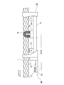
- FIG. 2 is a block diagram schematically showing the magnetization detector and the image capturing unit from the side. It is a flowchart which shows the flow of operation
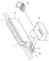
- FIG. 1 is a perspective view showing the entire configuration of the rope tester.
- FIG. 2 is a block diagram schematically showing, from the side, a magnetization detector and an image capturing unit which will be described below, which constitute a rope tester. The internal structure of the magnetization detector is shown in FIG.
- the rope tester comprises a magnetization detector 10, an image capturing unit 20, a controller 30, and a computer device 40.
- the magnetization detector 10 magnetizes a part of the elevator wire rope 1 to be inspected to form a magnetic circuit including a part of the elevator wire rope 1 and a defect exists in the elevator wire rope 1
- the change in the magnetic reluctance caused by is observed using the change in the magnetic flux or the magnetic flux.
- a magnetization detector 10 is provided with a wire rope passage recess 11 extending in one direction and having a substantially semicircular cross section.
- a wire rope 1 having a circular cross section is passed through the wire rope passage recess 11.
- the length in the longitudinal direction of the magnetization detector 10 (wire rope passage recess 11) is, for example, about 160 mm.
- a rectangular parallelepiped yoke 12 a pair of magnets 13 and 14 fixed on both sides of the upper surface of the yoke 12, and the pair of magnets 13 , 14 and provided with a coil base 15 fixed to the upper surface of the yoke 12 at a distance from each of the magnets 13 and 14, and a detection coil 16 fixed to the upper surface of the coil base 15 There is.
- the detection coil 16 is curved in a U-shape along the wire rope passage recess 11 in order to inspect most of the outer peripheral surface of the wire rope 1.
- a magnetic circuit is constituted by the magnets 13 and 14, the yoke 12, and a part of the wire rope 1 in the range sandwiched by the magnets 13 and 14.
- the cross-sectional area of the wire rope 1 decreases at the damaged point, and the magnetic resistance in the magnetic circuit increases.
- the increase in reluctance reduces the flux in the magnetic circuit described above. Since the magnetic flux flowing through the magnetic circuit links the detection coil 16, an electromotive force is generated in the detection coil 16 according to the change of the magnetic flux, and a voltage signal is output. The damage occurring in the wire rope 1 can be quantitatively evaluated based on the voltage signal output from the detection coil 16.
- the magnetic flux also changes at that point, and an electromotive force is generated in the detection coil 16. Since the cross-sectional area of the portion where the iron powder is deposited increases, an electromotive force different in polarity from the electromotive force generated when the above-described damage is present in the wire rope 1 is generated in the detection coil 16.
- the voltage signal output from the detection coil 16 can also be used to detect foreign matter attached to the wire rope 1.
- defects damage to the wire rope 1 (defect) and foreign matter adhesion to the wire rope 1 are collectively referred to as “defects”.
- the image capturing unit 20 includes a digital camera 21 and an illumination source 22 fixed on a pedestal 23.
- the digital camera 21 and the illumination source 22 both point in the direction of the wire rope 1, and the surface of the wire rope 1 brightly illuminated by the illumination source 22 can be photographed by the digital camera 21.
- An attachment 2 is provided between the magnetization detector 10 and the image capturing unit 20, and the magnetization detector 10 and the image capturing unit 20 can be integrated via the attachment 2.
- the magnetization detector 10, the digital camera 21 and the illumination source 22 described above and the computer device 40 described below are connected to the controller 30 by signal lines.
- the controller 30 includes a CPU (Central Processing Unit), a memory, a hard disk, a communication interface (all not shown), and the like, and receives and records voltage signals output from the magnetization detector 10 (detection coil 16), Power supply and drive (shooting instruction) to the digital camera 21, reception and recording of image data output from the digital camera 21, power supply to the illumination source 22, and data transmission to the computer device 40 are performed.
- a CPU Central Processing Unit
- memory main memory
- a hard disk a hard disk
- a communication interface all not shown
- the voltage signal output from the magnetization detector 10 (detection coil 16), the image data transmitted from the digital camera 21, the setting data set by the operator (measurement date and time, movement of the wire rope 1) in the memory included in the controller 30 The speed (rope speed), the diameter of the wire rope 1, the gain setting value, the threshold for judging defects (decision level), the distance between the detection coil 16 and the digital camera 21, etc. are recorded.
- An input device (input button) 31 provided in the controller 30 is used to input setting data.
- the controller 30 is also equipped with an interface (not shown) for loading and unloading the memory card itself, and data stored in the memory of the controller 30 can be recorded (transferred) in the memory card.
- the controller 30 outputs a warning when the presence of a defect is determined using the voltage signal output from the detection coil 16 (the voltage signal exceeds the threshold). (Lamp lighting, buzzer ringing, etc.) can also be performed.
- the computer device 40 includes a central processing unit (CPU), a memory, a hard disk, a communication device, an input device, a display device and the like, and data transmitted from the controller 30 through signal lines or recorded in a memory card in the controller 30
- CPU central processing unit
- a program to analyze the wire rope 1 is installed using the Details of processing (display screen) by the analysis program in the computer device 40 will be described later.
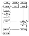
- FIG. 3 is a flow chart showing the operation flow of the controller 30, the magnetization detector 10 (detection coil 16), and the digital camera 21.
- the wire rope 1 is generally made by twisting a plurality of strands, and since there are helical irregularities on the surface, the cross-sectional area is not constant in the longitudinal direction due to the structure. Therefore, an output signal (voltage signal) is always output from the magnetization detector 10 (detection coil 16). The output signal from the magnetization detector 10 is given to the controller 30 through the signal line as described above (steps 58 and 51).
- the output signal from the magnetization detector 10 received by the controller 30 is sampled, for example, every 1 millisecond every predetermined time interval in the controller 30, and the sampled value (digital data representing the voltage value) is recorded in the memory Step 52).
- the output signal from the magnetization detector 10 is amplified using a gain set in advance by the controller 30, and the amplified output signal is sampled.
- the controller 30 compares each of the voltage values (sampling values) recorded in the memory with a predetermined threshold (step 53). If it is below the threshold value, the controller 30 does not execute any particular processing (NO in step 53).
- the magnetization detector 10 outputs a larger output signal (voltage value).
- wire rope 1 is not damaged, dust adheres to the surface of wire rope 1, for example, iron powder from a sheave to which wire rope 1 or wire rope 1 is applied is on the surface of wire rope 1 If deposited, the reluctance in the magnetic circuit described above also fluctuates in this case, and the output signal output from the magnetization detector 10 also fluctuates.
- the controller 30 counts a predetermined delay time (described in detail below) from the detection timing, and drives the digital camera 21 at a timing when the delay time has elapsed.
- the photographing instruction signal is transmitted (YES in step 53, steps 54 and 55).
- the digital camera 21 always stands by for a shooting instruction from the controller 30 (step 59, NO in step 60), and performs shooting at the timing when the shooting instruction signal from the controller 30 is received (YES in step 60, Step 61).
- Image data representing a portion of the wire rope 1 acquired by imaging is transmitted from the digital camera 21 to the controller 30 through the signal line (step 62).
- the controller 30 When the controller 30 receives the image data transmitted from the digital camera 21, the controller 30 records (stores) the received image data in the memory (steps 56 and 57). Image data can be recorded in memory in any file format (jpeg, gif, raw, etc.).
- Each of the image files stored in the memory can be accompanied by data specifying the photographing order.
- data specifying the shooting order may be attached by including the shooting time in the file name of the image file recorded in the memory by using the timing function of the controller 30, or the consecutive numbers may be stored in the memory It may be included in the file name of the image file to be recorded.
- data specifying the shooting order may be recorded in header information of the image file.
- each of the image files may be stored in memory to maintain a first in first out (FIFO) structure.
- FIFO first in first out
- an image capturing unit 20 is provided ahead of the moving direction of the wire rope 1 on the basis of the moving direction of the wire rope 1, and a magnetization detector 10 is provided behind it. There is. Since the moving wire rope 1 is continuously inspected using the fixedly installed rope tester system, the defect point of the wire rope 1 first passes the detection coil 16 and then the installation of the digital camera 21 I will pass the point.
- the moving speed of the wire rope 1 is y (m / min), and the distance between the detection coil 16 and the digital camera 21 is x (mm). Since the moving speed of the defect point of the wire rope 1 is equal to the moving speed of the wire rope 1, the moving speed of the defect point can be expressed by the following equation, assuming that the unit is mm / s.
- the controller 30 calculates the delay time described above using the moving speed y of the wire rope 1 and the distance x between the detection coil 16 and the digital camera 21 (previously calculated and recorded in the memory). The calculated delay time is used for timing control for transmitting a drive signal to the digital camera 21. For example, by using a clock signal of the CPU included in the controller 30, the controller 30 can output a drive signal to the digital camera 21 after a predetermined delay time has elapsed since a defect detection (detection of an output signal exceeding a threshold). it can.
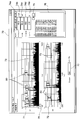
- FIG. 4 shows a screen of a display device of the computer device 40, and shows an example of a screen displayed by an analysis program installed in the computer device 40. As shown in FIG.
- An image file including output signals (voltage values) from the magnetization detector 10 (detection coil 16) at predetermined time intervals recorded in the memory of the controller 30, and image data representing the wire rope 1 captured by the digital camera 21.
- Data representing the measurement date and time when the wire rope 1 was inspected, the moving speed of the wire rope 1 (rope speed), rope diameter, gain setting value, and judgment level (threshold value) Is provided to the computer 40.
- an analysis window 70 shown in FIG. 4 is displayed on the display screen of the display device of the computer device 40.
- a measurement date display column 74a On the right side of the analysis window 70, a measurement date display column 74a, a rope speed display column 74b, a rope diameter display column 74c, a gain set value display column 74d, and a judgment level display column 74e are provided.
- the setting values set in the controller 30 are displayed in these display fields 74a to 74e.
- two output signal graph display fields 71 and 72 are displayed in upper and lower two stages, with the horizontal axis representing the position (m) of the wire rope 1 and the vertical axis representing the voltage value (V).
- a graph representing an output signal (voltage value) output from the above-described magnetization detector 10 (detection coil 16) is indicated by the length of a vertical straight line.
- the output signal from the magnetization detector 10 is sampled in order (time series) every predetermined time interval, for example, every one millisecond. Also, the moving speed (rope speed) of the wire rope 1 is known.
- each of the sampled multiple output signals can be correlated with the position of the wire rope 1 (the distance from the inspection start position when the inspection start position is 0.0 m),
- an output signal graph is created by the analysis program with the horizontal axis as the position (m) of the wire rope 1 and the vertical axis as the voltage value (v).
- the output signal graph display column 71 in the upper stage graphically displays the output signal over the entire inspection length of the wire rope 1.
- the total inspection length of the wire rope 1 is 150.8 m
- the lower output signal graph display field 72 shows an enlarged part of the range of the horizontal axis of the upper output signal graph display field 71, and is displayed below the upper output signal graph display field 71.
- the expansion range can be selected by moving the rectangular slider 78 left and right using an input device (mouse or the like).
- the enlargement ratio (the enlargement range) is variable, and the enlargement ratio is input to the enlargement ratio input field 77 displayed in the lower central part of the analysis window 70.
- the width of the rectangular slider 78 expands and contracts in accordance with the size of the enlargement ratio.
- lines 73 indicating threshold values are also displayed in different colors (for example, in red), and a graph representing an output signal of a voltage value exceeding this threshold line 73
- the tip of is marked (e.g. a red circle is shown at the tip of the graph).
- the determination button 75 provided on the right side of the analysis window 70 When the determination button 75 provided on the right side of the analysis window 70 is clicked, the position of the wire rope 1 at which the output signal of the voltage value exceeding the threshold value is detected, that is, the defect position is displayed in a list in the list display column 76 Be done.
- the list display column 76 displays, for each of the detected defect points, a continuous number, the distance from the inspection start position, and the distance from the immediately preceding defect point.
- thumbnail images 80 corresponding to respective graphs representing output signals of voltage values exceeding the threshold line 73 are further displayed.
- the thumbnail image 80 is an image of a portion of the wire rope 1 captured by the digital camera 21 when an output signal exceeding the threshold is detected.
- a process of creating image data representing the thumbnail image 80 from the image data output from the digital camera 21 is performed by the computer device 40 (analysis program).
- thumbnail image data may be created in the digital camera 21 or the controller 30.
- the graphs of the many output signals displayed in the output signal graph display fields 71 and 72 are arranged in time series from left to right It is a thing. Further, as described above, the wire rope 1 is photographed by the digital camera 21 because a defect is detected based on an output signal from the magnetization detector 10 (detection coil 16) (a voltage value exceeding the threshold is detected. And each of the image files also includes data specifying its imaging order as described above.
- an image based on the original image data used to create the clicked thumbnail image 80 may be displayed on the display screen (enlarged display).
- the appearance of the defect can be confirmed in detail on the display screen.
- the appearance image of the defect can be confirmed, so that it is difficult to understand when only the magnetization detector 10 is used.
- More specific conditions of the wire rope 1 such as the number can be confirmed in detail.
- the range of the wire rope 1 for finding a defect in the field, or the range of the wire rope 1 to be carefully inspected in the field can be greatly narrowed, and efficient field inspection can be realized. It is also possible to significantly reduce oversight of defects in
- the numerical value representing the threshold value displayed in the judgment level display field 74e on the right side of the analysis window 70 can be replaced with another numerical value.
- the threshold line 73 of the output signal graph display fields 71 and 72 moves upward. Since the top of the graph representing the output signal of the voltage value exceeding the newly input threshold value is marked and the thumbnail images 80 are displayed in association, the number of displayed thumbnail images 80 generally decreases. That is, only the thumbnail image 80 of a portion where the degree of defect is considered to be large can be displayed in the output signal graph display fields 71 and 72.
- the thumbnail image 80 can not be displayed in association with a graph representing an output signal that is only to exceed the threshold value by reducing the threshold value, since shooting is not performed.
- the threshold value set in the controller 30 in advance to a small value, in general, the number of locations to be judged as defects increases, so that more locations of the wire rope 1 will be photographed. Needless to say.
- a plurality of the wire ropes 1 are simultaneously tested by arranging a plurality of magnetization detectors 10 and image capturing units 20 in parallel. It can also be done. In this case, output signal graph display fields 71 and 72 for each of the plurality of wire ropes 1 are displayed in the analysis window 70 (an analysis window 70 for each wire rope 1 is created).
- the configuration in which the wire rope 1 is photographed from one direction using one digital camera 21 is shown, but the same portion of the wire rope 1 is photographed from different directions using a plurality of digital cameras 21 May be A wider range in the circumferential direction of the wire rope 1 or a full range in the circumferential direction can be checked.
Landscapes
- Chemical & Material Sciences (AREA)
- General Health & Medical Sciences (AREA)
- Immunology (AREA)
- Health & Medical Sciences (AREA)
- Analytical Chemistry (AREA)
- Biochemistry (AREA)
- Physics & Mathematics (AREA)
- General Physics & Mathematics (AREA)
- Life Sciences & Earth Sciences (AREA)
- Pathology (AREA)
- Engineering & Computer Science (AREA)
- Textile Engineering (AREA)
- Chemical Kinetics & Catalysis (AREA)
- Electrochemistry (AREA)
- Investigating Or Analyzing Materials By The Use Of Magnetic Means (AREA)
Priority Applications (5)
| Application Number | Priority Date | Filing Date | Title |
|---|---|---|---|
| SG11202005244QA SG11202005244QA (en) | 2017-12-12 | 2018-12-10 | Rope tester, wire rope analyzing apparatus and control program therefor |
| MYPI2020002696A MY202794A (en) | 2017-12-12 | 2018-12-10 | Rope tester, wire rope analyzing apparatus and control program therefor |
| EP18888688.1A EP3726204B1 (en) | 2017-12-12 | 2018-12-10 | Rope tester, wire rope analyzing apparatus and control program thereof |
| CN201880079372.4A CN111512147A (zh) | 2017-12-12 | 2018-12-10 | 绳索试验机、金属线绳解析装置及其控制程序 |
| US16/896,782 US11543386B2 (en) | 2017-12-12 | 2020-06-09 | Rope tester, wire rope analyzing apparatus and control program therefor |
Applications Claiming Priority (2)
| Application Number | Priority Date | Filing Date | Title |
|---|---|---|---|
| JP2017237676A JP6956616B2 (ja) | 2017-12-12 | 2017-12-12 | ロープテスタ,ワイヤロープ解析装置およびその制御プログラム |
| JP2017-237676 | 2017-12-12 |
Related Child Applications (1)
| Application Number | Title | Priority Date | Filing Date |
|---|---|---|---|
| US16/896,782 Continuation US11543386B2 (en) | 2017-12-12 | 2020-06-09 | Rope tester, wire rope analyzing apparatus and control program therefor |
Publications (1)
| Publication Number | Publication Date |
|---|---|
| WO2019117079A1 true WO2019117079A1 (ja) | 2019-06-20 |
Family
ID=66820339
Family Applications (1)
| Application Number | Title | Priority Date | Filing Date |
|---|---|---|---|
| PCT/JP2018/045293 Ceased WO2019117079A1 (ja) | 2017-12-12 | 2018-12-10 | ロープテスタ,ワイヤロープ解析装置およびその制御プログラム |
Country Status (7)
| Country | Link |
|---|---|
| US (1) | US11543386B2 (https=) |
| EP (1) | EP3726204B1 (https=) |
| JP (1) | JP6956616B2 (https=) |
| CN (1) | CN111512147A (https=) |
| MY (1) | MY202794A (https=) |
| SG (1) | SG11202005244QA (https=) |
| WO (1) | WO2019117079A1 (https=) |
Cited By (3)
| Publication number | Priority date | Publication date | Assignee | Title |
|---|---|---|---|---|
| CN112456293A (zh) * | 2020-12-14 | 2021-03-09 | 中铁第四勘察设计院集团有限公司 | 可实时标记的自动扶梯扶手带内嵌钢丝监测系统及方法 |
| CN113820274A (zh) * | 2021-08-20 | 2021-12-21 | 中国电子科技集团公司第三十八研究所 | 一种可移动式缆绳质量检测集成装置 |
| CN121048548A (zh) * | 2025-11-03 | 2025-12-02 | 江苏神韵绳缆有限公司 | 一种基于机器人的钢丝绳不平整度测量方法 |
Families Citing this family (11)
| Publication number | Priority date | Publication date | Assignee | Title |
|---|---|---|---|---|
| JP7187855B2 (ja) * | 2018-07-11 | 2022-12-13 | 株式会社島津製作所 | 磁性体検査システム、磁性体検査装置および磁性体検査方法 |
| US11506632B2 (en) * | 2020-10-20 | 2022-11-22 | Obshchestvo s ogranichennoi otvetstvennostiu “INTRON PLIUS” | Method for predicting a residual operating life of a steel rope |
| US11480546B2 (en) | 2020-12-23 | 2022-10-25 | Shimadzu Corporation | Magnetic material inspection system, magnetic material inspection device, and magnetic material inspection method |
| JP7491236B2 (ja) * | 2021-02-16 | 2024-05-28 | 株式会社島津製作所 | ワイヤロープ検査方法、ワイヤロープ検査システムおよびワイヤロープ検査装置 |
| JP7652012B2 (ja) * | 2021-08-23 | 2025-03-27 | 株式会社島津製作所 | ワイヤロープ検査装置 |
| JP7768022B2 (ja) * | 2022-04-19 | 2025-11-12 | 株式会社島津製作所 | ワイヤロープ検査装置 |
| JP7668775B2 (ja) * | 2022-10-05 | 2025-04-25 | 株式会社三井E&S | ワイヤロープの点検方法および点検システム並びにクレーン |
| CN117007671B (zh) * | 2023-08-03 | 2025-12-12 | 中国长江三峡集团有限公司 | 钢丝绳检查装置、方法、控制单元及控制系统 |
| CN117554467B (zh) * | 2023-11-13 | 2024-11-19 | 甘肃三有智能科技有限公司 | 一种敞开式钢丝绳检测装置及方法 |
| US20250239386A1 (en) * | 2024-01-23 | 2025-07-24 | Te Connectivity Solutions Gmbh | System and Method To Handle Lax Objects |
| CN119795081A (zh) * | 2025-03-11 | 2025-04-11 | 江苏星火特钢集团有限公司 | 一种钢丝绳夹持调节装置 |
Citations (5)
| Publication number | Priority date | Publication date | Assignee | Title |
|---|---|---|---|---|
| JP2009012903A (ja) | 2007-07-03 | 2009-01-22 | Mitsubishi Electric Building Techno Service Co Ltd | エレベータ用ワイヤーロープの素線切れ検査装置及びその方法 |
| JP3156764U (ja) * | 2009-10-30 | 2010-01-14 | 住友金属工業株式会社 | 表面疵検査装置 |
| JP2011105495A (ja) * | 2009-11-20 | 2011-06-02 | Meidensha Corp | ワイヤーロープ検査装置 |
| WO2013145823A1 (ja) * | 2012-03-28 | 2013-10-03 | 三菱電機株式会社 | ワイヤロープ検査装置 |
| CN105293242A (zh) * | 2015-11-25 | 2016-02-03 | 佛山住友富士电梯有限公司 | 一种电梯曳引绳检测装置 |
Family Cites Families (6)
| Publication number | Priority date | Publication date | Assignee | Title |
|---|---|---|---|---|
| JPH11230946A (ja) * | 1998-02-10 | 1999-08-27 | Hitachi Building Systems Co Ltd | ワイヤーロープの磁気探傷装置 |
| JP3547342B2 (ja) * | 1999-07-30 | 2004-07-28 | 株式会社日立ビルシステム | ワイヤーロープの磁気探傷装置 |
| MY150395A (en) * | 2006-04-04 | 2014-01-15 | Tokyo Rope Mfg Co | Wire rope remote surveillance system |
| JP5003351B2 (ja) * | 2007-08-23 | 2012-08-15 | Jfeスチール株式会社 | 磁性金属帯の微小表面欠陥の品質検査方法及び装置 |
| CN104515777B (zh) * | 2015-01-14 | 2017-03-08 | 兖州煤业股份有限公司 | 强磁‑图像联合钢丝绳在线无损探伤系统及方法 |
| CN106018544B (zh) * | 2016-06-24 | 2018-03-20 | 窦柏林 | 一种钢丝绳全息检测系统 |
-
2017
- 2017-12-12 JP JP2017237676A patent/JP6956616B2/ja active Active
-
2018
- 2018-12-10 SG SG11202005244QA patent/SG11202005244QA/en unknown
- 2018-12-10 EP EP18888688.1A patent/EP3726204B1/en active Active
- 2018-12-10 CN CN201880079372.4A patent/CN111512147A/zh active Pending
- 2018-12-10 MY MYPI2020002696A patent/MY202794A/en unknown
- 2018-12-10 WO PCT/JP2018/045293 patent/WO2019117079A1/ja not_active Ceased
-
2020
- 2020-06-09 US US16/896,782 patent/US11543386B2/en active Active
Patent Citations (5)
| Publication number | Priority date | Publication date | Assignee | Title |
|---|---|---|---|---|
| JP2009012903A (ja) | 2007-07-03 | 2009-01-22 | Mitsubishi Electric Building Techno Service Co Ltd | エレベータ用ワイヤーロープの素線切れ検査装置及びその方法 |
| JP3156764U (ja) * | 2009-10-30 | 2010-01-14 | 住友金属工業株式会社 | 表面疵検査装置 |
| JP2011105495A (ja) * | 2009-11-20 | 2011-06-02 | Meidensha Corp | ワイヤーロープ検査装置 |
| WO2013145823A1 (ja) * | 2012-03-28 | 2013-10-03 | 三菱電機株式会社 | ワイヤロープ検査装置 |
| CN105293242A (zh) * | 2015-11-25 | 2016-02-03 | 佛山住友富士电梯有限公司 | 一种电梯曳引绳检测装置 |
Non-Patent Citations (1)
| Title |
|---|
| See also references of EP3726204A4 |
Cited By (3)
| Publication number | Priority date | Publication date | Assignee | Title |
|---|---|---|---|---|
| CN112456293A (zh) * | 2020-12-14 | 2021-03-09 | 中铁第四勘察设计院集团有限公司 | 可实时标记的自动扶梯扶手带内嵌钢丝监测系统及方法 |
| CN113820274A (zh) * | 2021-08-20 | 2021-12-21 | 中国电子科技集团公司第三十八研究所 | 一种可移动式缆绳质量检测集成装置 |
| CN121048548A (zh) * | 2025-11-03 | 2025-12-02 | 江苏神韵绳缆有限公司 | 一种基于机器人的钢丝绳不平整度测量方法 |
Also Published As
| Publication number | Publication date |
|---|---|
| EP3726204A4 (en) | 2021-08-25 |
| EP3726204A1 (en) | 2020-10-21 |
| JP2019105507A (ja) | 2019-06-27 |
| US20200300811A1 (en) | 2020-09-24 |
| JP6956616B2 (ja) | 2021-11-02 |
| SG11202005244QA (en) | 2020-07-29 |
| EP3726204C0 (en) | 2023-11-29 |
| CN111512147A (zh) | 2020-08-07 |
| EP3726204B1 (en) | 2023-11-29 |
| MY202794A (en) | 2024-05-22 |
| US11543386B2 (en) | 2023-01-03 |
Similar Documents
| Publication | Publication Date | Title |
|---|---|---|
| JP6956616B2 (ja) | ロープテスタ,ワイヤロープ解析装置およびその制御プログラム | |
| US9665932B2 (en) | Camera based cable inspection system | |
| CN104185786B (zh) | 缆绳检查装置 | |
| JP2009512879A (ja) | 走行する撚り線を検査する方法及び装置 | |
| JP5428798B2 (ja) | ワイヤーロープ検査装置 | |
| JP2019105507A5 (https=) | ||
| JP5786622B2 (ja) | 画質検査方法、画質検査装置及び画質検査プログラム | |
| JP2011232111A5 (https=) | ||
| JP2020033137A (ja) | エレベータロープ検査装置及びエレベータロープ検査方法 | |
| JP2019169022A (ja) | 品質監視システム | |
| JP7271866B2 (ja) | 磁性体検査システムおよびプログラム | |
| JP5481232B2 (ja) | パンタグラフ監視装置 | |
| JP2020020125A (ja) | レール検査方法 | |
| JP5243486B2 (ja) | ケーブル位置検出装置、ケーブル位置検出方法及びケーブル位置検出プログラム | |
| KR20140126479A (ko) | 케이블 손상 신호 처리 장치 및 방법 | |
| JP7155040B2 (ja) | ワイヤロープの検査方法および検査システム | |
| JP2010523958A (ja) | 金属板生産ラインにおける残留酸化物の検出及び分類装置 | |
| Gronau et al. | NDT of steel ropes with magnetic flaw detectors: documentation and interpretation of test result | |
| JP2009237648A (ja) | 作業者安全検査装置 | |
| JP5375239B2 (ja) | 画像処理装置、長尺物用検査装置及びコンピュータプログラム | |
| KR200236696Y1 (ko) | 콘크리트 구조물의 크랙 검출 및 영상처리장치 | |
| JP2002090306A (ja) | 表面検査装置の自己診断方法 | |
| JP4513722B2 (ja) | 監視制御装置及び監視制御方法 | |
| KR20220129655A (ko) | 승강기의 진단 장치 및 진단 해석 장치 | |
| JP7323380B2 (ja) | 綱状構造体の維持管理方法及び綱状構造体の維持管理装置 |
Legal Events
| Date | Code | Title | Description |
|---|---|---|---|
| 121 | Ep: the epo has been informed by wipo that ep was designated in this application |
Ref document number: 18888688 Country of ref document: EP Kind code of ref document: A1 |
|
| NENP | Non-entry into the national phase |
Ref country code: DE |
|
| ENP | Entry into the national phase |
Ref document number: 2018888688 Country of ref document: EP Effective date: 20200713 |