WO2019111381A1 - 超音波探傷装置 - Google Patents
超音波探傷装置 Download PDFInfo
- Publication number
- WO2019111381A1 WO2019111381A1 PCT/JP2017/044038 JP2017044038W WO2019111381A1 WO 2019111381 A1 WO2019111381 A1 WO 2019111381A1 JP 2017044038 W JP2017044038 W JP 2017044038W WO 2019111381 A1 WO2019111381 A1 WO 2019111381A1
- Authority
- WO
- WIPO (PCT)
- Prior art keywords
- ultrasonic
- reception
- steel plate
- processing unit
- echo
- Prior art date
Links
Images


Classifications
-
- G—PHYSICS
- G01—MEASURING; TESTING
- G01N—INVESTIGATING OR ANALYSING MATERIALS BY DETERMINING THEIR CHEMICAL OR PHYSICAL PROPERTIES
- G01N29/00—Investigating or analysing materials by the use of ultrasonic, sonic or infrasonic waves; Visualisation of the interior of objects by transmitting ultrasonic or sonic waves through the object
- G01N29/04—Analysing solids
- G01N29/07—Analysing solids by measuring propagation velocity or propagation time of acoustic waves
-
- G—PHYSICS
- G01—MEASURING; TESTING
- G01N—INVESTIGATING OR ANALYSING MATERIALS BY DETERMINING THEIR CHEMICAL OR PHYSICAL PROPERTIES
- G01N29/00—Investigating or analysing materials by the use of ultrasonic, sonic or infrasonic waves; Visualisation of the interior of objects by transmitting ultrasonic or sonic waves through the object
- G01N29/04—Analysing solids
- G01N29/043—Analysing solids in the interior, e.g. by shear waves
-
- G—PHYSICS
- G01—MEASURING; TESTING
- G01N—INVESTIGATING OR ANALYSING MATERIALS BY DETERMINING THEIR CHEMICAL OR PHYSICAL PROPERTIES
- G01N29/00—Investigating or analysing materials by the use of ultrasonic, sonic or infrasonic waves; Visualisation of the interior of objects by transmitting ultrasonic or sonic waves through the object
- G01N29/04—Analysing solids
- G01N29/06—Visualisation of the interior, e.g. acoustic microscopy
- G01N29/0654—Imaging
- G01N29/069—Defect imaging, localisation and sizing using, e.g. time of flight diffraction [TOFD], synthetic aperture focusing technique [SAFT], Amplituden-Laufzeit-Ortskurven [ALOK] technique
-
- G—PHYSICS
- G01—MEASURING; TESTING
- G01N—INVESTIGATING OR ANALYSING MATERIALS BY DETERMINING THEIR CHEMICAL OR PHYSICAL PROPERTIES
- G01N29/00—Investigating or analysing materials by the use of ultrasonic, sonic or infrasonic waves; Visualisation of the interior of objects by transmitting ultrasonic or sonic waves through the object
- G01N29/04—Analysing solids
- G01N29/11—Analysing solids by measuring attenuation of acoustic waves
-
- G—PHYSICS
- G01—MEASURING; TESTING
- G01N—INVESTIGATING OR ANALYSING MATERIALS BY DETERMINING THEIR CHEMICAL OR PHYSICAL PROPERTIES
- G01N29/00—Investigating or analysing materials by the use of ultrasonic, sonic or infrasonic waves; Visualisation of the interior of objects by transmitting ultrasonic or sonic waves through the object
- G01N29/22—Details, e.g. general constructional or apparatus details
- G01N29/221—Arrangements for directing or focusing the acoustical waves
-
- G—PHYSICS
- G01—MEASURING; TESTING
- G01N—INVESTIGATING OR ANALYSING MATERIALS BY DETERMINING THEIR CHEMICAL OR PHYSICAL PROPERTIES
- G01N29/00—Investigating or analysing materials by the use of ultrasonic, sonic or infrasonic waves; Visualisation of the interior of objects by transmitting ultrasonic or sonic waves through the object
- G01N29/22—Details, e.g. general constructional or apparatus details
- G01N29/24—Probes
- G01N29/2487—Directing probes, e.g. angle probes
-
- G—PHYSICS
- G01—MEASURING; TESTING
- G01N—INVESTIGATING OR ANALYSING MATERIALS BY DETERMINING THEIR CHEMICAL OR PHYSICAL PROPERTIES
- G01N29/00—Investigating or analysing materials by the use of ultrasonic, sonic or infrasonic waves; Visualisation of the interior of objects by transmitting ultrasonic or sonic waves through the object
- G01N29/22—Details, e.g. general constructional or apparatus details
- G01N29/26—Arrangements for orientation or scanning by relative movement of the head and the sensor
- G01N29/262—Arrangements for orientation or scanning by relative movement of the head and the sensor by electronic orientation or focusing, e.g. with phased arrays
-
- G—PHYSICS
- G01—MEASURING; TESTING
- G01N—INVESTIGATING OR ANALYSING MATERIALS BY DETERMINING THEIR CHEMICAL OR PHYSICAL PROPERTIES
- G01N29/00—Investigating or analysing materials by the use of ultrasonic, sonic or infrasonic waves; Visualisation of the interior of objects by transmitting ultrasonic or sonic waves through the object
- G01N29/44—Processing the detected response signal, e.g. electronic circuits specially adapted therefor
- G01N29/4472—Mathematical theories or simulation
-
- G—PHYSICS
- G01—MEASURING; TESTING
- G01N—INVESTIGATING OR ANALYSING MATERIALS BY DETERMINING THEIR CHEMICAL OR PHYSICAL PROPERTIES
- G01N29/00—Investigating or analysing materials by the use of ultrasonic, sonic or infrasonic waves; Visualisation of the interior of objects by transmitting ultrasonic or sonic waves through the object
- G01N29/44—Processing the detected response signal, e.g. electronic circuits specially adapted therefor
- G01N29/48—Processing the detected response signal, e.g. electronic circuits specially adapted therefor by amplitude comparison
-
- G—PHYSICS
- G01—MEASURING; TESTING
- G01N—INVESTIGATING OR ANALYSING MATERIALS BY DETERMINING THEIR CHEMICAL OR PHYSICAL PROPERTIES
- G01N2291/00—Indexing codes associated with group G01N29/00
- G01N2291/01—Indexing codes associated with the measuring variable
- G01N2291/011—Velocity or travel time
-
- G—PHYSICS
- G01—MEASURING; TESTING
- G01N—INVESTIGATING OR ANALYSING MATERIALS BY DETERMINING THEIR CHEMICAL OR PHYSICAL PROPERTIES
- G01N2291/00—Indexing codes associated with group G01N29/00
- G01N2291/02—Indexing codes associated with the analysed material
- G01N2291/023—Solids
- G01N2291/0234—Metals, e.g. steel
-
- G—PHYSICS
- G01—MEASURING; TESTING
- G01N—INVESTIGATING OR ANALYSING MATERIALS BY DETERMINING THEIR CHEMICAL OR PHYSICAL PROPERTIES
- G01N2291/00—Indexing codes associated with group G01N29/00
- G01N2291/02—Indexing codes associated with the analysed material
- G01N2291/028—Material parameters
- G01N2291/0289—Internal structure, e.g. defects, grain size, texture
-
- G—PHYSICS
- G01—MEASURING; TESTING
- G01N—INVESTIGATING OR ANALYSING MATERIALS BY DETERMINING THEIR CHEMICAL OR PHYSICAL PROPERTIES
- G01N2291/00—Indexing codes associated with group G01N29/00
- G01N2291/04—Wave modes and trajectories
- G01N2291/042—Wave modes
- G01N2291/0427—Flexural waves, plate waves, e.g. Lamb waves, tuning fork, cantilever
-
- G—PHYSICS
- G01—MEASURING; TESTING
- G01N—INVESTIGATING OR ANALYSING MATERIALS BY DETERMINING THEIR CHEMICAL OR PHYSICAL PROPERTIES
- G01N2291/00—Indexing codes associated with group G01N29/00
- G01N2291/04—Wave modes and trajectories
- G01N2291/044—Internal reflections (echoes), e.g. on walls or defects
-
- G—PHYSICS
- G01—MEASURING; TESTING
- G01N—INVESTIGATING OR ANALYSING MATERIALS BY DETERMINING THEIR CHEMICAL OR PHYSICAL PROPERTIES
- G01N2291/00—Indexing codes associated with group G01N29/00
- G01N2291/04—Wave modes and trajectories
- G01N2291/056—Angular incidence, angular propagation
-
- G—PHYSICS
- G01—MEASURING; TESTING
- G01N—INVESTIGATING OR ANALYSING MATERIALS BY DETERMINING THEIR CHEMICAL OR PHYSICAL PROPERTIES
- G01N2291/00—Indexing codes associated with group G01N29/00
- G01N2291/04—Wave modes and trajectories
- G01N2291/057—Angular incidence, parallel to surface propagation
-
- G—PHYSICS
- G01—MEASURING; TESTING
- G01N—INVESTIGATING OR ANALYSING MATERIALS BY DETERMINING THEIR CHEMICAL OR PHYSICAL PROPERTIES
- G01N2291/00—Indexing codes associated with group G01N29/00
- G01N2291/10—Number of transducers
- G01N2291/106—Number of transducers one or more transducer arrays
-
- G—PHYSICS
- G01—MEASURING; TESTING
- G01N—INVESTIGATING OR ANALYSING MATERIALS BY DETERMINING THEIR CHEMICAL OR PHYSICAL PROPERTIES
- G01N2291/00—Indexing codes associated with group G01N29/00
- G01N2291/26—Scanned objects
- G01N2291/263—Surfaces
- G01N2291/2632—Surfaces flat
Definitions
- the present invention relates to an ultrasonic flaw detector that determines the properties of a test body using ultrasonic waves.
- flaws may occur on the front and back surfaces, and such flaws are detected by an ultrasonic flaw detector.
- ultrasonic waves are obliquely incident on the steel plate by the probe, and flaw detection is performed by plate waves or surface waves.
- an ultrasonic flaw detector there has been a device in which an ultrasonic wave is obliquely incident on a steel plate from a tire probe and flaw detection of a surface flaw is performed using a surface wave (for example, see Patent Document 1) ).
- the present invention has been made to solve such a problem, and an object thereof is to provide an ultrasonic flaw detection apparatus capable of determining whether a flaw position is on the front side or the back side of a steel plate.
- the ultrasonic flaw detector generates an ultrasonic wave corresponding to a given transmission signal to transmit the ultrasonic wave into the test body, and receives and receives an echo of the ultrasonic wave propagated in the test body.
- An ultrasound probe that outputs an echo as a reception signal; and a transmission signal processing unit that generates, as a transmission signal, a signal from which the ultrasound probe transmits an ultrasonic wave in a diagonal direction at a plurality of angles with respect to a test object.
- reception signal processing unit for specifying the position.
- the ultrasonic flaw detection apparatus transmits ultrasonic waves in a plurality of angles obliquely with respect to the test body, determines the amplitude and reception time of the echo according to the plurality of angles, and their amplitude ratio and reception time Therefore, the position of the acoustic discontinuity in the test body is specified. This makes it possible to determine whether the flaw position is on the front side or the back side of the specimen.
- FIGS. 1 to 6E are explanatory diagrams of simulation conditions of the ultrasonic flaw detection apparatus according to the first embodiment of the present invention.
- FIGS. 1 to 6E are explanatory diagrams of simulation conditions of the ultrasonic flaw detection apparatus according to the first embodiment of the present invention.
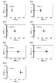
- FIGS. 7A to 7G are explanatory views showing echoes in the case where flaws on the front side of a steel plate are flawed when the incident angle is 34.5 ° in the ultrasonic flaw detector according to the first embodiment of the present invention.
- 8A to 8G are explanatory diagrams showing echoes in the case where flaws on the front side of a steel plate are flawed when the incident angle is 24.6 ° in the ultrasonic flaw detector according to the first embodiment of the present invention. It is explanatory drawing which shows the change of the echo height with respect to the distance in case the flaw in the ultrasonic flaw detection apparatus of Embodiment 1 of this invention is on the front side of a steel plate.
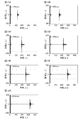
- 10A to 10G are explanatory diagrams showing echoes in the case where flaws on the back side of a steel plate are flawed when the incident angle is 34.5 ° in the ultrasonic flaw detector according to the first embodiment of the present invention.
- 11A to 11G are explanatory diagrams showing echoes in the case where flaws on the back side of a steel plate are flawed when the incident angle is 24.6 ° in the ultrasonic flaw detector according to the first embodiment of the present invention.
- FIG. 1 is a block diagram of an ultrasonic flaw detector according to the present embodiment.
- the illustrated ultrasonic flaw detector comprises an ultrasonic probe 1 and a transmitter / receiver 2.
- the ultrasonic probe 1 is an oblique angle probe, transmits an ultrasonic wave driven by a given transmission signal into the steel plate 100 as a test object, and echoes of the ultrasonic wave propagated in the steel plate 100 , And outputs this as a reception signal.
- the detail of the ultrasound probe 1 is shown in FIG. As shown in FIG. 2, the ultrasound probe 1 includes a wedge 1 a and a transducer 1 b.
- the vibrator 1 b is configured by arraying a plurality of vibration elements.
- the transmitter / receiver 2 has a function of providing a transmission signal to the ultrasound probe 1 and performing signal processing on the reception signal of the echo acquired by the ultrasound probe 1.
- the signal processing unit 3 and the transmission unit 4 The receiving unit 5.
- the signal processing unit 3 includes a transmission signal processing unit 3a and a reception signal processing unit 3b.
- the transmission signal processing unit 3a has a function of generating, as a transmission signal, a signal by which the ultrasonic probe 1 transmits ultrasonic waves in a diagonal direction at a plurality of angles with respect to the steel plate 100 and gives this to the transmitting unit 4. ing.
- the reception signal processing unit 3b receives the reception signal acquired by the ultrasonic probe 1 through the reception unit 5, determines the amplitudes and reception times of ultrasonic echoes corresponding to a plurality of angles from the reception signal, and obtains these The position of the acoustic discontinuity in the steel sheet 100 is determined from the amplitude ratio of and the reception time.
- the transmission unit 4 has a function of generating a signal for driving the transducer 1 b of the ultrasound probe 1 based on the transmission signal from the transmission signal processing unit 3 a.
- the receiving unit 5 has a function of amplifying the reception signal from the ultrasound probe 1 as necessary and transmitting the amplified signal to the reception signal processing unit 3 b of the signal processing unit 3.
- FIG. 3 is a block diagram schematically showing an example of the hardware configuration of the signal processing unit 3.
- the example in FIG. 3 includes a processor 301 including a CPU, a read only memory (ROM) 302, a random access memory (RAM) 303, a storage 304, a transmission / reception interface circuit 305, a display interface circuit 306, and a display 307. .
- the processor 301, the ROM 302, the RAM 303, the storage 304, the transmission / reception interface circuit 305, the display interface circuit 306, and the display 307 are mutually connected via a signal path 308 such as a bus circuit.
- the processor 301 uses the RAM 303 as a working memory and executes the ultrasonic measurement program read from the ROM 302 or the storage 304 to realize the functions of the transmission signal processing unit 3a and the reception signal processing unit 3b.
- the storage 304 is configured using, for example, volatile memory such as SDRAM (Synchronous DRAM) or HDD (Hard Disk Drive) or SSD (Solid State Drive), and functions of the transmission signal processing unit 3a and the reception signal processing unit 3b. It is a storage unit that stores corresponding programs and stores processing results.
- the transmission / reception interface circuit 305 is an interface circuit used for signal transmission with the transmission unit 4 and signal transmission with the reception unit 5.
- the display interface circuit 306 is an interface circuit used for signal transmission to and from the display 307.
- the display 307 displays the determination result of the flaw position.
- the result may be displayed as characters or may be displayed by an LED lamp.
- the display method is not limited.
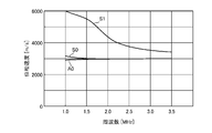
- FIGS. 4 and 5 show the phase velocity and group velocity of a plate wave propagating through a steel plate having a thickness of 3.6 mm, respectively.
- the phase velocity and the group velocity differ depending on the frequency.
- the three modes of A0, S0 and S1 are shown here.
- a plate wave propagating at a frequency of 2.25 MHz and a steel plate having a thickness of 3.6 mm will be described.
- the phase velocity is about 3000 m / s for both A0 and S0, which are almost the same. Therefore, if the incident angle of the ultrasonic probe 1 is set so that a plate wave with a phase velocity of 3000 m / s propagates, it is considered that a mode having features of both A0 and S0 propagates. In this embodiment, this mode is referred to as "A0S0 mode". On the other hand, the phase velocity of S1 is about 4000 m / s. If the incident angle of the ultrasound probe 1 is set so that a plate wave having a phase velocity of 4000 m / s propagates, a plate wave of the S1 mode propagates.
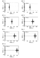
- FIG. 6A and 6B show the response characteristics of the ultrasound probe 1 used in the simulation, and FIG. 6A shows the relationship between time and relative amplitude, and FIG. 6B shows the relationship between frequency and relative amplitude.
- FIG. 6B it was set as the narrow band by center frequency 2.25 MHz.
- 6C and 6D are diagrams showing the relative positional relationship between the ultrasound probe 1 and the steel plate 100 when the flaw 101 is on the front side and the back side of the steel plate 100, respectively. As shown in FIGS.
- FIG. 6E is a flaw shape.
- FIG. 6E shows the flaw 101 on the front side of the steel plate 100, and in the case of the reverse side, the flaw shape is vertically reversed.
- the vibrator 1 b was brought into contact with a liquid having a sound velocity of 1680 m / s, and the liquid was used as a wedge 1 a to constitute an oblique angle probe.
- the incident angle for generating the A0S0 mode with a phase velocity of 3000 m / s can be determined according to Snell's law: It becomes.
- the incident angle for propagating the A0S0 mode is set to 34.5 °.
- the incidence angle for generating S1 mode with a phase velocity of 4000 m / s is It becomes.
- the incident angle for propagating the S1 mode is set to 24.6 °.
- 7A to 7G show echoes in the case where the A0S0 mode is propagated at an incident angle of 34.5 ° and the flaw 101 on the front side of the steel plate 100 is flawed.
- 7A to 7G show examples of the distance 150 mm to the distance 450 mm, respectively. As illustrated, the echo height decreases with the distance up to about 350 mm, but increases after 400 mm.
- FIG. 8A to 8G show examples of the distance 150 mm to the distance 450 mm, respectively. As shown, the echo height gradually decreases with distance.
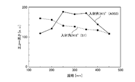
- the change of the echo height with distance when the flaw 101 is on the front side of the steel plate 100 is shown in FIG. As shown, while the echo height of the S1 mode generated at an incident angle of 24.6 ° gradually decreases with distance, the echo height of the A0S0 mode generated at an incident angle of 34.5 ° is It shows a complex characteristic of decreasing and then increasing.
- FIG. 10A to 10G show examples of the distance 150 mm to the distance 450 mm, respectively. As shown, the echo height increases with distance, but decreases beyond 350 mm. This is the opposite tendency to the case where the flaw 101 is on the front side.
- FIG. 11 shows an echo in the case where the S1 mode is propagated with an incident angle of 24.6 ° and the flaw 101 on the back side of the steel plate 100 is flawed.
- 11A to 11G show examples of the distance 150 mm to the distance 450 mm, respectively. As shown, the echo height gradually decreases with distance. This is the same tendency as in the case where the flaw 101 is on the front side.
- the change of the echo height with distance when the flaw 101 is on the back side of the steel plate 100 is shown in FIG.
- the echo height of the S1 mode generated at an incident angle of 24.6 ° gradually decreases with distance, while the echo height of the A0S0 mode generated at an incident angle of 34.5 ° increases.
- FIG. 13 shows a sound field simulation result (distance 300 mm) in the case of propagating the A0S0 mode with the incident angle of 34.5 °.
- the sound field in the vicinity of the ultrasonic probe 1 is shown, and in 90 ⁇ s to 110 ⁇ s, the sound field in the vicinity of the flaw 101 is shown.
- the energy of the plate wave is gathered on the front side of the steel plate 100.
- the energy distribution of the plate wave is gathered on the back side of the steel plate 100 when the energy distribution changes little by little with the propagation and reaches the flaw 101 located at a distance of 300 mm.
- FIG. 1 What represented transiently the transition of the energy distribution of A0S0 mode is shown in FIG.
- the energy of the plate wave is stronger on the front side of the steel plate 100.
- the energy distribution changes with the propagation, and the energy distribution on the back side becomes stronger through the state of the same energy distribution on the front side and the back side.
- the change in echo height with distance is reversed between the case where the flaw 101 is on the front side and the case where the flaw 101 is on the back side of the steel plate 100.
- the A0S0 mode has the characteristics as shown in FIGS.
- FIG. 15 shows the result of sound field simulation (distance 300 mm) in the case of propagating the S1 mode with the incident angle 24.6 °.
- the sound field in the vicinity of the ultrasonic probe 1 is shown at 10 ⁇ s to 30 ⁇ s
- the sound field in the vicinity of the flaw 101 is shown at 120 ⁇ s to 140 ⁇ s.
- the sound field distribution hardly changes and is almost uniform in the thickness direction also immediately after entering the steel plate 100 from the ultrasonic probe 1 and when reaching the flaw 101.
- the change in echo height with distance is largely different.
- the specific operation of the ultrasonic flaw detector according to the present embodiment will be described.
- FIG. 17 is a flowchart showing the operation of the transmission signal processing unit 3a
- FIG. 18 is a flowchart showing the operation of the reception signal processing unit 3b.
- the ultrasonic wave propagation condition in the wedge 1a in the case where the delay time given to the left end element of the arrayed transducers 1b is long and the delay time given to the right end element is short is shown.
- the incident angle which A0S0 mode propagates changes with the thickness of the steel plate 100, the sound speed of the wedge 1a, and a frequency, it is not necessarily the angle (34.5 degrees) shown by simulation.
- a plate wave in the A0S0 mode propagates in the steel plate 100, and the plate wave reflected by the flaw 101 is received as an echo by each transducer element of the arrayed transducers 1b in the ultrasound probe 1, It is converted into an electrical signal and sent to the receiver 5.
- the receiver 5 amplifies the echo if necessary and sends it to the signal processor 3.
- the reception signal processing unit 3b gives an echo a delay time corresponding to each of the transducer elements of the arrayed transducers 1b, and synthesizes the echoes of the respective transducer elements.
- the amplitude of this echo is determined as E1 and the reception time as T1, and the values of E1 and T1 are stored in the RAM 303 and storage 304 constituting the received signal processing unit 3b (step ST21). That is, the incident angle and the receiving angle are controlled by the phased array method, and the plate wave of the A0S0 mode is propagated in the steel plate 100 to perform transmission and reception.
- the incident angle is changed by the phased array method, and a plate wave of S1 mode is generated in the steel plate 100. That is, a delay signal corresponding to each of the transducer elements of the arrayed transducers 1b is sent from the transmission signal processing unit 3a to the transmission unit 4 so that the incident angle at which the S1 mode propagates is obtained (step ST12).
- the incident angle which S1 mode propagates changes with the thickness of the steel plate 100, the sound speed of the wedge 1a, and a frequency, it is not necessarily the angle (24.6 degrees) shown by simulation.
- the S1 mode plate wave propagates in the steel plate 100, and the plate wave reflected by the flaw 101 is received as an echo by each transducer element of the arrayed transducers 1b in the ultrasonic probe 1, It is converted into an electrical signal and sent to the receiver 5.
- the receiver 5 amplifies the echo if necessary and sends it to the signal processor 3.
- the reception signal processing unit 3b obtains the echo amplitude E2 and the reception time T2 of the S1 mode in the phased array method, and stores them in the RAM 303 and the storage 304 constituting the reception signal processing unit 3b (step ST22). .
- the group velocity of the plate wave is also determined. That is, it is possible to estimate the distance from the ultrasound probe 1 to the flaw 101 from the echo reception time. For example, since the group velocity of the A0S0 mode is approximately 3000 m / s regardless of the frequency, the round-trip propagation distance of the A0S0 mode can be obtained from T1 ⁇ 3000 m / s.
- the distance from the ultrasonic probe 1 to the flaw 101 is determined by the reception signal processing unit 3b, and is set to L (step ST23).
- the change in echo height with distance as shown in FIGS. 9 and 12 is previously obtained by calculation or experiment.
- the reception signal processing unit 3b compares the amplitude E1 of the A0S0 mode and the amplitude E2 of the S1 mode to determine whether the flaw 101 is on the front side or the back side of the steel plate 100 based on the characteristics of echo height with respect to distance. (Step ST24). For example, if the characteristics of the echo height with respect to the distance are the same as in FIGS. 9 and 12, if the value of the distance L is 300 mm, then E1 ⁇ E2 The crack 101 is on the front side of the steel plate 100 (step ST25) E1> E2 The flaw 101 is on the back side of the steel plate 100 (step ST26) The relationship is clear.
- the reception signal processing unit 3 b displays the determination result on the display 307. As described above, it is possible to determine whether the flaw 101 is on the front side or the back side of the steel plate 100 by using the plate waves of two modes.
- the steel plate 100 is mechanically scanned as the ultrasound probe 1.
- the ultrasonic waves may be transmitted at a plurality of angles with respect to.
- the ultrasonic probe 1 may be a variable angle type probe to obtain a plurality of angles.
- multiple angles may be obtained using a plurality of oblique angle probes having different incident angles.
- the ultrasonic flaw detection apparatus using the oblique angle probe has been described in the above example, in the case of an ultrasonic probe in which ultrasonic waves are obliquely incident on the steel plate 100, not the oblique angle probe It does not matter.
- an ultrasonic wave corresponding to a given transmission signal is generated to transmit the ultrasonic wave into the test body, and the ultrasonic wave propagated through the test body is generated.
- the ultrasonic probe which receives the echo of the sound wave and outputs the received echo as a reception signal, and the transmission signal which the ultrasonic probe transmits the ultrasonic wave in the oblique direction at a plurality of angles with respect to the test body
- the transmit signal processor determines the amplitudes of echoes corresponding to multiple angles and the time from transmission of ultrasonic waves to reception of echoes as reception time, and from these amplitude ratio and reception time, Since the reception signal processing unit for specifying the position of the acoustic discontinuity in the body is provided, it is possible to determine whether the defect position is on the front side or the back side of the test body.
- the transducers of the ultrasonic probe are formed of a plurality of arrayed transducer elements, and the transmission signal processing unit is different for the plurality of transducer elements. Since a signal having a delay time is generated as a signal corresponding to a plurality of angles, a configuration for transmitting ultrasonic waves at a plurality of angles can be easily realized.
- the ultrasonic probe transmits ultrasonic waves obliquely at a plurality of angles with respect to the test body by mechanically scanning.
- Various probes can be selected as ultrasonic probes.
- the ultrasonic flaw detection apparatus As described above, according to the ultrasonic flaw detection apparatus according to the present invention, plate waves of different modes are propagated into the test body using the ultrasonic probe, and the amplitude ratio and reception time of the plurality of received echoes are used.
- the present invention relates to a configuration for determining the properties of a test body, and is suitable for flaw detection including whether the flaws of a steel plate are on the front or back.
- Reference Signs List 1 ultrasonic probe, 1a wedge, 1b transducer, 2 transceivers, 3 signal processing unit, 3a transmission signal processing unit, 3b reception signal processing unit, 4 transmitting unit, 5 receiving unit, 100 steel plate, 101 flaws.
Landscapes
- Physics & Mathematics (AREA)
- General Physics & Mathematics (AREA)
- General Health & Medical Sciences (AREA)
- Pathology (AREA)
- Life Sciences & Earth Sciences (AREA)
- Chemical & Material Sciences (AREA)
- Analytical Chemistry (AREA)
- Biochemistry (AREA)
- Health & Medical Sciences (AREA)
- Immunology (AREA)
- Acoustics & Sound (AREA)
- Signal Processing (AREA)
- Engineering & Computer Science (AREA)
- Algebra (AREA)
- Mathematical Analysis (AREA)
- Mathematical Optimization (AREA)
- Mathematical Physics (AREA)
- Pure & Applied Mathematics (AREA)
- Investigating Or Analyzing Materials By The Use Of Ultrasonic Waves (AREA)
Abstract
超音波探触子(1)は送信信号処理部(3a)からの送信信号により、鋼板(100)に対して複数の角度で斜め方向に超音波を送出する。また、超音波探触子(1)は、鋼板(100)からの複数の角度に応じたエコーを受信する。受信信号処理部(3b)は、超音波探触子(1)で受信された複数の角度に応じたエコーの振幅と超音波の送出からエコーの受信までの時間を受信時間として求め、これらの振幅比と受信時間から、鋼板(100)中におけるきず(101)の位置を特定する。
Description
この発明は、超音波を用いて試験体の性状を判断する超音波探傷装置に関するものである。
鉄鋼メーカなどで製造される鋼板では、表面や裏面にきずが発生する場合があり、このようなきずは超音波探傷装置で検出される。
鋼材が薄い場合には、探触子により超音波を斜めに鋼板内に入射し、板波あるいは表面波による探傷が行われている。従来、このような超音波探傷装置として、タイヤ探触子から鋼板に対して斜めに超音波を入射し、表面波を用いて表面きずの探傷を行うものがあった(例えば、特許文献1参照)。
ところで、超音波探傷装置において、きずの位置が鋼板の表側にあるか裏側にあるかを把握したい場合がある。しかしながら、上記特許文献1に記載されたような従来の超音波探傷装置では、きず位置の表裏判別は困難であった。
この発明は、かかる問題を解決するためになされたもので、きず位置が鋼板の表側にあるのか裏側にあるのかを判断することのできる超音波探傷装置を提供することを目的とする。
この発明に係る超音波探傷装置は、与えられる送信信号に対応した超音波を生成して超音波を試験体中に送出すると共に、試験体中を伝搬した超音波のエコーを受信し、受信したエコーを受信信号として出力する超音波探触子と、超音波探触子が試験体に対して複数の角度で斜め方向に超音波を送出する信号を送信信号として生成する送信信号処理部と、受信信号から、複数の角度に応じたエコーの振幅と超音波の送出からエコーの受信までの時間を受信時間として求め、これらの振幅比と受信時間から、試験体中における音響的不連続部の位置を特定する受信信号処理部とを備えたものである。
この発明に係る超音波探傷装置は、試験体に対して複数の角度で斜め方向に超音波を送出し、複数の角度に応じたエコーの振幅と受信時間を求め、これらの振幅比と受信時間から、試験体中における音響的不連続部の位置を特定するようにしたものである。これにより、きず位置が試験体の表側にあるのか裏側にあるのかを判断することができる。
以下、この発明をより詳細に説明するために、この発明を実施するための形態について、添付の図面に従って説明する。
実施の形態1.
図1は、本実施の形態による超音波探傷装置の構成図である。
図示の超音波探傷装置は、超音波探触子1と送受信器2を備えている。超音波探触子1は斜角探触子であり、与えられる送信信号によって駆動される超音波を、試験体である鋼板100中に送信し、かつ、鋼板100中を伝搬した超音波のエコーを受信し、これを受信信号として出力する機能を有している。超音波探触子1の詳細を図2に示す。図2に示すように、超音波探触子1は、くさび1aと振動子1bを備えている。振動子1bは複数の振動素子をアレイ化して構成されている。
実施の形態1.
図1は、本実施の形態による超音波探傷装置の構成図である。
図示の超音波探傷装置は、超音波探触子1と送受信器2を備えている。超音波探触子1は斜角探触子であり、与えられる送信信号によって駆動される超音波を、試験体である鋼板100中に送信し、かつ、鋼板100中を伝搬した超音波のエコーを受信し、これを受信信号として出力する機能を有している。超音波探触子1の詳細を図2に示す。図2に示すように、超音波探触子1は、くさび1aと振動子1bを備えている。振動子1bは複数の振動素子をアレイ化して構成されている。
送受信器2は、超音波探触子1に対して送信信号を与えると共に超音波探触子1で取得したエコーの受信信号に対する信号処理を行う機能を有し、信号処理部3、送信部4、受信部5を備えている。信号処理部3は、送信信号処理部3aと受信信号処理部3bからなる。送信信号処理部3aは、超音波探触子1が鋼板100に対して複数の角度で斜め方向に超音波を送出する信号を送信信号として生成し、これを送信部4に与える機能を有している。受信信号処理部3bは、超音波探触子1で取得した受信信号を受信部5を介して受け取り、この受信信号から、複数の角度に応じた超音波エコーの振幅と受信時間を求め、これらの振幅比と受信時間から、鋼板100中における音響的不連続部の位置を特定する機能を有している。送信部4は、送信信号処理部3aからの送信信号に基づいて超音波探触子1の振動子1bを駆動するための信号を生成する機能を有している。受信部5は、超音波探触子1からの受信信号を必要に応じて増幅して信号処理部3の受信信号処理部3bに送信する機能を有している。
図3は、信号処理部3のハードウェア構成例を概略的に示すブロック図である。図3の例では、CPUを含むプロセッサ301、ROM(Read Only Memory)302、RAM(Random Access Memory)303、ストレージ304、送受信インタフェース回路305、表示インタフェース回路306、及び表示器307を有している。プロセッサ301、ROM302、RAM303、ストレージ304、送受信インタフェース回路305、表示インタフェース回路306及び表示器307は、バス回路などの信号路308を介して相互に接続されている。
プロセッサ301は、RAM303を作業用メモリとして使用し、ROM302またはストレージ304から読み出された超音波測定用プログラムを実行して送信信号処理部3a及び受信信号処理部3bの機能を実現する。ストレージ304は、例えば、SDRAM(Synchronous DRAM)などの揮発性メモリ、またはHDD(ハードディスクドライブ)もしくはSSD(ソリッドステートドライブ)を用いて構成され、送信信号処理部3a及び受信信号処理部3bの機能に対応したプログラムを格納したり、処理結果を格納したりする記憶部である。送受信インタフェース回路305は、送信部4との間の信号伝達と受信部5との間の信号伝達に使用されるインタフェース回路である。表示インタフェース回路306は、表示器307との間の信号伝達に使用されるインタフェース回路である。
表示器307は、きず位置の判定結果を表示するものである。結果は文字として表示しても良いし、LEDランプで表示しても良い。表示方法は限定されるものではない。
次に、本実施の形態の超音波探傷装置の動作について説明する。先ず、鋼板内を伝搬する板波について図4及び図5を参照して説明する。図4及び図5は、それぞれ厚さ3.6mmの鋼板を伝搬する板波の位相速度及び群速度を示すものである。これらの図から明らかなように周波数によって位相速度及び群速度が異なる。なお、実際には多くのモードが伝搬するが、ここではA0,S0及びS1の三つのモードについて示している。ここでは、例として、周波数2.25MHzで厚さ3.6mmの鋼板を伝搬する板波について説明する。
図4に示すように、周波数2.25MHzの場合には、A0とS0共に位相速度は約3000m/sとなり、殆ど同じとなる。従って、位相速度3000m/sの板波が伝搬するように超音波探触子1の入射角を設定すれば、A0とS0の両方の特徴を有するモードが伝搬すると考えられる。本実施の形態では、このモードを「A0S0モード」と呼ぶことにする。一方、S1の位相速度は約4000m/sとなる。位相速度4000m/sの板波が伝搬するように超音波探触子1の入射角を設定すれば、S1モードの板波が伝搬していく。
A0S0モード及びS0モードの板波を伝搬させて鋼板100のきず101を探傷した場合、どのようなエコーが受信されるかを調べるため、シミュレーションを行った。図6にシミュレーション条件を示す。図6A及び図6Bは、シミュレーションで用いた超音波探触子1の応答特性であり、図6Aは時間と相対振幅の関係、図6Bは周波数と相対振幅の関係を示している。この例では、図6Bに示すように、中心周波数2.25MHzで狭帯域とした。図6C及び図6Dは、それぞれ、きず101が鋼板100の表側及び裏側にある場合の、超音波探触子1と鋼板100との相対的な位置関係を示す図である。図6C及び図6Dに示すように、超音波探触子1からきず101までの距離Lを150mmから450mmまで変化させ、きず101からのエコーを求めた。図6Eは、きず形状である。図6Eでは、鋼板100の表側にあるきず101を示しており、裏側にある場合にはきず形状は上下反転したものとなる。
シミュレーションでは、振動子1bを音速1680m/sの液体に接触させ、この液体をくさび1aとして斜角探触子を構成した。この場合、位相速度3000m/sのA0S0モードを発生させるための入射角は、スネルの法則より、

となる。ここではシミュレーションの都合上、A0S0モードを伝搬させるための入射角として、34.5°とした。一方、位相速度4000m/sのS1モードを発生させるための入射角は、

となる。ここではシミュレーションの都合上、S1モードを伝搬させるための入射角として、24.6°とした。
となる。ここではシミュレーションの都合上、A0S0モードを伝搬させるための入射角として、34.5°とした。一方、位相速度4000m/sのS1モードを発生させるための入射角は、
となる。ここではシミュレーションの都合上、S1モードを伝搬させるための入射角として、24.6°とした。
入射角を34.5°としてA0S0モードを伝搬させ、鋼板100表側にあるきず101を探傷した場合のエコーを図7A~図7Gに示す。図7A~図7Gは距離150mm~距離450mmの例をそれぞれ示している。図示のように、距離350mm程度までは距離と共にエコー高さは低減していくが、400mm以降は増加傾向を示している。
入射角を24.6°としてS1モードを伝搬させ、鋼板100表側にあるきずを探傷した場合のエコーを図8に示す。図8A~図8Gは距離150mm~距離450mmの例をそれぞれ示している。図示のように、エコー高さは距離と共に緩やかに低減していく。
きず101が鋼板100の表側にある場合の、距離に対するエコー高さの変化を図9に示す。図示のように、入射角24.6°で発生させたS1モードのエコー高さは距離と共に緩やかに低減するのに対し、入射角34.5°で発生させたA0S0モードのエコー高さは、低減した後に増加するという複雑な特性を示している。
入射角を34.5°としてA0S0モードを伝搬させ、鋼板100裏側にあるきず101を探傷した場合のエコーを図10に示す。図10A~図10Gは距離150mm~距離450mmの例をそれぞれ示している。図示のように、距離と共にエコー高さは増加するが、350mmを超えると低減していく。これは、きず101が表側にある場合と逆の傾向である。
入射角を24.6°としてS1モードを伝搬させ、鋼板100裏側にあるきず101を探傷した場合のエコーを図11に示す。図11A~図11Gに距離150mm~距離450mmの例をそれぞれ示している。図示のように、エコー高さは距離と共に緩やかに低減していく。これは、きず101が表側にある場合と同じ傾向である。
きず101が鋼板100の裏側にある場合の、距離に対するエコー高さの変化を図12に示す。図示のように、入射角24.6°で発生させたS1モードのエコー高さは距離と共に緩やかに低減するのに対し、入射角34.5°で発生させたA0S0モードのエコー高さは増加した後に低減するという複雑な特性を示している。
図9及び図12に示したような特性となる原因を、図13~図16を参照して説明する。図13は、入射角34.5°としてA0S0モードを伝搬させた場合の音場シミュレーション結果(距離300mm)である。図13において、10μs~30μsでは超音波探触子1付近の音場を示し、90μs~110μsではきず101付近の音場を示している。図示のように、超音波探触子1から鋼板100に入射した直後では、鋼板100の表側に板波のエネルギが集まっている。伝搬に伴いエネルギ分布が少しずつ変化し、距離300mmの位置にあるきず101に到達する時には、板波のエネルギは鋼板100の裏側に集まっている。
A0S0モードのエネルギ分布の推移を模擬的に表したものを図14に示す。図示のように、超音波探触子1から鋼板100に入射した直後には、鋼板100の表側の方が板波のエネルギは強くなる。伝搬と共にエネルギ分布が変化し、表側と裏側とで同程度のエネルギ分布という状態を経て、裏側の方がエネルギが強くなるという状態になる。その後、再び表側と裏側とで同程度のエネルギ分布という状態を経て、表側のほうがエネルギは強くなる、という伝搬の仕方をする。従って、きず101が鋼板100の表側にある場合と裏側にある場合とでは、距離に対するエコー高さの変化が逆転する。その結果、A0S0モードは、図9及び図12に示したような特性となる。
図15は、入射角24.6°としてS1モードを伝搬させた場合の音場シミュレーション結果(距離300mm)である。図15において、10μs~30μsでは超音波探触子1付近の音場を示し、120μs~140μsではきず101付近の音場を示している。図示のように、超音波探触子1から鋼板100に入射した直後も、きず101に到達する時も、音場分布は殆ど変わらず、板厚方向に対してほぼ一様となっている。
S1モードのエネルギ分布の推移を模擬的に表したものを、図16に示す。図示のように、伝搬してもエネルギ分布は殆ど変わらない。板厚方向に対してほぼ一様となっているので、きず101が鋼板100の表側にある場合と裏側にある場合とで、距離に対するエコー高さの変化は殆ど同じとなる。その結果、S1モードは図9及び図12に示したような特性となる。
以上説明したように、A0S0モードとS1モードとでは、距離に対するエコー高さの変化が大きく異なる。この特徴を用いれば、きず101が鋼板100の表側にあるのか、あるいは裏側にあるのかを判別することが可能である。以下、本実施の形態の超音波探傷装置の具体的な動作について説明する。
図17は送信信号処理部3aの動作を示すフローチャート、図18は受信信号処理部3bの動作を示すフローチャートである。
まず、A0S0モードが伝搬する入射角となるように、送信信号処理部3aから送信部4に対して、アレイ化した振動子1bの振動素子毎に応じた遅延信号を送る(ステップST11)。送信部4では、送信信号処理部3aからの遅延信号により励振信号を発生させ、超音波探触子1内にあるアレイ化した振動子1bの各振動素子を励振する。図2の例では、アレイ化した振動子1bの左端素子へ与える遅延時間が長く、右端素子へ与える遅延時間が短い場合の、くさび1a内の超音波伝搬状況を示している。なお、A0S0モードが伝搬する入射角は、鋼板100の厚さ、くさび1aの音速及び周波数により変化するので、シミュレーションで示した角度(34.5°)とは限らない。
まず、A0S0モードが伝搬する入射角となるように、送信信号処理部3aから送信部4に対して、アレイ化した振動子1bの振動素子毎に応じた遅延信号を送る(ステップST11)。送信部4では、送信信号処理部3aからの遅延信号により励振信号を発生させ、超音波探触子1内にあるアレイ化した振動子1bの各振動素子を励振する。図2の例では、アレイ化した振動子1bの左端素子へ与える遅延時間が長く、右端素子へ与える遅延時間が短い場合の、くさび1a内の超音波伝搬状況を示している。なお、A0S0モードが伝搬する入射角は、鋼板100の厚さ、くさび1aの音速及び周波数により変化するので、シミュレーションで示した角度(34.5°)とは限らない。
その後、A0S0モードの板波が鋼板100内を伝搬していき、きず101で反射された板波を超音波探触子1内のアレイ化した振動子1bの各振動素子でエコーとして受信し、電気信号に変換して受信部5に送る。受信部5では、必要があればエコーを増幅し、信号処理部3に送る。
信号処理部3では、受信信号処理部3bが、アレイ化した振動子1bの振動素子毎に応じた遅延時間をエコーに与え、各振動素子のエコーを合成する。このエコーの振幅をE1、受信時間をT1として求め、これらE1及びT1の値を受信信号処理部3bを構成するRAM303やストレージ304に記憶する(ステップST21)。すなわち、フェーズドアレイ方式で入射角及び受信する角度を制御して、鋼板100内にA0S0モードの板波を伝搬させ、送受信を行う。
E1及びT1を受信信号処理部3bに記憶した後、フェーズドアレイ方式で入射角を変え、鋼板100内にS1モードの板波を発生させる。すなわち、送信信号処理部3aより、S1モードが伝搬する入射角となるよう、送信部4に対して、アレイ化した振動子1bの振動素子毎に応じた遅延信号を送る(ステップST12)。なお、S1モードが伝搬する入射角は、鋼板100の厚さ、くさび1aの音速及び周波数により変化するので、シミュレーションで示した角度(24.6°)とは限らない。
その後、S1モードの板波が鋼板100内を伝搬していき、きず101で反射された板波を超音波探触子1内のアレイ化した振動子1bの各振動素子でエコーとして受信し、電気信号に変換して受信部5に送る。受信部5では、必要があればエコーを増幅し、信号処理部3に送る。
信号処理部3では、受信信号処理部3bが、フェーズドアレイ方式でS1モードのエコーの振幅E2及び受信時間T2を求め、受信信号処理部3bを構成するRAM303やストレージ304に記憶する(ステップST22)。
図5に示したように、周波数が決まれば板波の群速度も決まる。すなわち、エコーの受信時間から、超音波探触子1からきず101までの距離を推定することが可能である。例えば、A0S0モードの群速度は周波数に依らずほぼ3000m/sなので、T1×3000m/sから、A0S0モードの往復伝搬距離を求めることができる。受信信号処理部3bで、超音波探触子1からきず101までの距離を求め、Lとする(ステップST23)。
図9及び図12に示したような、距離に対するエコー高さの変化を予め計算あるいは実験で求めておく。受信信号処理部3bで、A0S0モードの振幅E1とS1モードの振幅E2を比較して、距離に対するエコー高さの特性から、きず101が鋼板100の表側にあるのか、裏側にあるのかを判別する(ステップST24)。例えば、距離に対するエコー高さの特性が、図9及び図12と同様であれば、距離Lの値が300mmの場合は、
・E1<E2 きず101は鋼板100の表側にある(ステップST25)
・E1>E2 きず101は鋼板100の裏側にある(ステップST26)
という関係が明らかである。受信信号処理部3bは、この判別結果を表示器307に表示する。
このように、二つのモードの板波を用いることにより、きず101が鋼板100の表側にあるのか、裏側にあるのかを判別することが可能である。
・E1<E2 きず101は鋼板100の表側にある(ステップST25)
・E1>E2 きず101は鋼板100の裏側にある(ステップST26)
という関係が明らかである。受信信号処理部3bは、この判別結果を表示器307に表示する。
このように、二つのモードの板波を用いることにより、きず101が鋼板100の表側にあるのか、裏側にあるのかを判別することが可能である。
なお、上記例では、フェーズドアレイ方式の超音波探触子1でA0S0モード及びS1モードを送受信する構成及び動作について説明したが、超音波探触子1として、機械的に走査することで鋼板100に対して複数の角度で超音波を送出するようにしてもよい。例えば、超音波探触子1を可変角タイプの探触子とし、複数の角度を得るものでも良い。また、入射角の異なる斜角探触子を複数個用いて複数の角度を得ても良い。また、上記例では斜角探触子を用いた超音波探傷装置について説明したが、鋼板100に対して斜めに超音波を入射する超音波探触子であれば、斜角探触子でなくても構わない。
以上説明したように、実施の形態1の超音波探傷装置によれば、与えられる送信信号に対応した超音波を生成して超音波を試験体中に送出すると共に、試験体中を伝搬した超音波のエコーを受信し、受信したエコーを受信信号として出力する超音波探触子と、超音波探触子が試験体に対して複数の角度で斜め方向に超音波を送出する信号を送信信号として生成する送信信号処理部と、受信信号から、複数の角度に応じたエコーの振幅と超音波の送出からエコーの受信までの時間を受信時間として求め、これらの振幅比と受信時間から、試験体中における音響的不連続部の位置を特定する受信信号処理部とを備えたので、きず位置が試験体の表側にあるのか裏側にあるのかを判断することができるという効果がある。
また、実施の形態1の超音波探傷装置によれば、超音波探触子の振動子をアレイ化した複数の振動素子で形成すると共に、送信信号処理部は、複数の振動素子に対応した異なる遅延時間を有する信号を複数の角度に対応した信号として生成するようにしたので、複数の角度で超音波を送出する構成を容易に実現することができる。
また、実施の形態1の超音波探傷装置によれば、超音波探触子は、機械的に走査することで試験体に対して複数の角度で斜め方向に超音波を送出するようにしたので、超音波探触子として種々の探触子を選択することができる。
なお、本願発明はその発明の範囲内において、実施の形態の任意の構成要素の変形、もしくは実施の形態の任意の構成要素の省略が可能である。
以上のように、この発明に係る超音波探傷装置は、超音波探触子を用いて異なる複数のモードの板波を試験体中に伝搬させ、受信した複数のエコーの振幅比と受信時間から、試験体の性状を判断する構成に関するものであり、鋼板のきずを表裏のどちらにあるかを含めて探傷するのに適している。
1 超音波探触子、1a くさび、1b 振動子、2 送受信器、3 信号処理部、3a 送信信号処理部、3b 受信信号処理部、4 送信部、5 受信部、100 鋼板、101 きず。
Claims (3)
- 与えられる送信信号に対応した超音波を生成して当該超音波を試験体中に送出すると共に、前記試験体中を伝搬した前記超音波のエコーを受信し、当該受信したエコーを受信信号として出力する超音波探触子と、
前記超音波探触子が前記試験体に対して複数の角度で斜め方向に超音波を送出する信号を前記送信信号として生成する送信信号処理部と、
前記受信信号から、前記複数の角度に応じたエコーの振幅と前記超音波の送出から当該エコーの受信までの時間を受信時間として求め、これらの振幅比と受信時間から、前記試験体中における音響的不連続部の位置を特定する受信信号処理部とを備えたことを特徴とする超音波探傷装置。 - 前記超音波探触子の振動子をアレイ化した複数の振動素子で形成すると共に、
前記送信信号処理部は、前記複数の振動素子に対応した異なる遅延時間を有する信号を前記複数の角度に対応した信号として生成することを特徴とする請求項1記載の超音波探傷装置。 - 前記超音波探触子は、機械的に走査することで前記試験体に対して複数の角度で斜め方向に超音波を送出することを特徴とすることを特徴とする請求項1記載の超音波探傷装置。
Priority Applications (4)
| Application Number | Priority Date | Filing Date | Title |
|---|---|---|---|
| PCT/JP2017/044038 WO2019111381A1 (ja) | 2017-12-07 | 2017-12-07 | 超音波探傷装置 |
| JP2019557948A JP6671565B2 (ja) | 2017-12-07 | 2017-12-07 | 超音波探傷装置 |
| US16/757,685 US11307174B2 (en) | 2017-12-07 | 2017-12-07 | Ultrasonic flaw detection device |
| EP17933982.5A EP3722801B1 (en) | 2017-12-07 | 2017-12-07 | Ultrasonic flaw detection method |
Applications Claiming Priority (1)
| Application Number | Priority Date | Filing Date | Title |
|---|---|---|---|
| PCT/JP2017/044038 WO2019111381A1 (ja) | 2017-12-07 | 2017-12-07 | 超音波探傷装置 |
Publications (1)
| Publication Number | Publication Date |
|---|---|
| WO2019111381A1 true WO2019111381A1 (ja) | 2019-06-13 |
Family
ID=66750212
Family Applications (1)
| Application Number | Title | Priority Date | Filing Date |
|---|---|---|---|
| PCT/JP2017/044038 WO2019111381A1 (ja) | 2017-12-07 | 2017-12-07 | 超音波探傷装置 |
Country Status (4)
| Country | Link |
|---|---|
| US (1) | US11307174B2 (ja) |
| EP (1) | EP3722801B1 (ja) |
| JP (1) | JP6671565B2 (ja) |
| WO (1) | WO2019111381A1 (ja) |
Cited By (2)
| Publication number | Priority date | Publication date | Assignee | Title |
|---|---|---|---|---|
| JP2020153810A (ja) * | 2019-03-20 | 2020-09-24 | 三菱電機株式会社 | 液体検知方法および液体検知装置 |
| US11143625B2 (en) * | 2019-11-14 | 2021-10-12 | The Boeing Company | Ultrasonic inspection of parts |
Families Citing this family (1)
| Publication number | Priority date | Publication date | Assignee | Title |
|---|---|---|---|---|
| US11578971B2 (en) | 2021-02-12 | 2023-02-14 | Holloway Ndt & Engineering Inc. | Ultrasonic testing using a phased array |
Citations (4)
| Publication number | Priority date | Publication date | Assignee | Title |
|---|---|---|---|---|
| US4570487A (en) * | 1980-04-21 | 1986-02-18 | Southwest Research Institute | Multibeam satellite-pulse observation technique for characterizing cracks in bimetallic coarse-grained component |
| JPH06331603A (ja) | 1993-05-18 | 1994-12-02 | Nippon Steel Corp | 鋼板表面疵探傷方法 |
| JP2013156166A (ja) * | 2012-01-30 | 2013-08-15 | Mitsubishi Heavy Ind Ltd | 超音波探傷方法 |
| JP2013242202A (ja) * | 2012-05-18 | 2013-12-05 | Hitachi-Ge Nuclear Energy Ltd | 超音波検査方法及び超音波検査装置 |
Family Cites Families (13)
| Publication number | Priority date | Publication date | Assignee | Title |
|---|---|---|---|---|
| US4294118A (en) * | 1979-10-29 | 1981-10-13 | Sumitomo Kinzoku Kogyo Kabushiki Kaisha | Fully automatic ultrasonic flaw detection apparatus |
| US4435984A (en) | 1980-04-21 | 1984-03-13 | Southwest Research Institute | Ultrasonic multiple-beam technique for detecting cracks in bimetallic or coarse-grained materials |
| US4497210A (en) * | 1982-07-05 | 1985-02-05 | Tokyo Shibaura Denki Kabushiki Kaisha | Phased array ultrasonic testing apparatus and testing method therefor |
| JPS62261955A (ja) * | 1986-05-09 | 1987-11-14 | Toshiba Corp | 超音波探傷装置 |
| DE3715914A1 (de) | 1987-05-13 | 1988-12-01 | Fraunhofer Ges Forschung | Verfahren und vorrichtung zum nachweis von rissen mit hilfe von ultraschall |
| WO1991002971A1 (en) * | 1989-08-21 | 1991-03-07 | Hitachi Construction Machinery Co., Ltd. | Ultrasonic flaw detector |
| DE9214948U1 (de) | 1992-11-03 | 1994-03-10 | Siemens AG, 80333 München | Ultraschallwandler-Anordnung |
| EP0829714A4 (en) * | 1996-03-28 | 2007-06-27 | Mitsubishi Electric Corp | ULTRASONIC SOUND DETECTOR AND ULTRASONIC PROCEDURE FOR DETECTING ERRORS |
| DE19627957A1 (de) * | 1996-07-11 | 1998-01-15 | Bbc Reaktor Gmbh | Ultraschallwinkelprüfkopf und Verfahren zum Betreiben des Winkelprüfkopfes |
| US5814731A (en) * | 1997-01-28 | 1998-09-29 | Alexander; Alton Michel | Ultrasonic scanning apparatus for nondestructive site characterization of structures using a planar based acoustic transmitter and receiver in a rolling pond |
| JP4552309B2 (ja) * | 2000-11-02 | 2010-09-29 | 株式会社Ihi | 超音波探傷方法及び装置 |
| US7093490B2 (en) * | 2004-02-23 | 2006-08-22 | Hitachi, Ltd. | Ultrasonic flaw detecting method and ultrasonic flaw detector |
| JP5800667B2 (ja) * | 2011-10-17 | 2015-10-28 | 日立Geニュークリア・エナジー株式会社 | 超音波検査方法,超音波探傷方法及び超音波検査装置 |
-
2017
- 2017-12-07 US US16/757,685 patent/US11307174B2/en active Active
- 2017-12-07 WO PCT/JP2017/044038 patent/WO2019111381A1/ja unknown
- 2017-12-07 JP JP2019557948A patent/JP6671565B2/ja active Active
- 2017-12-07 EP EP17933982.5A patent/EP3722801B1/en active Active
Patent Citations (4)
| Publication number | Priority date | Publication date | Assignee | Title |
|---|---|---|---|---|
| US4570487A (en) * | 1980-04-21 | 1986-02-18 | Southwest Research Institute | Multibeam satellite-pulse observation technique for characterizing cracks in bimetallic coarse-grained component |
| JPH06331603A (ja) | 1993-05-18 | 1994-12-02 | Nippon Steel Corp | 鋼板表面疵探傷方法 |
| JP2013156166A (ja) * | 2012-01-30 | 2013-08-15 | Mitsubishi Heavy Ind Ltd | 超音波探傷方法 |
| JP2013242202A (ja) * | 2012-05-18 | 2013-12-05 | Hitachi-Ge Nuclear Energy Ltd | 超音波検査方法及び超音波検査装置 |
Non-Patent Citations (1)
| Title |
|---|
| See also references of EP3722801A4 |
Cited By (3)
| Publication number | Priority date | Publication date | Assignee | Title |
|---|---|---|---|---|
| JP2020153810A (ja) * | 2019-03-20 | 2020-09-24 | 三菱電機株式会社 | 液体検知方法および液体検知装置 |
| JP7236893B2 (ja) | 2019-03-20 | 2023-03-10 | 三菱電機株式会社 | 液体検知方法および液体検知装置 |
| US11143625B2 (en) * | 2019-11-14 | 2021-10-12 | The Boeing Company | Ultrasonic inspection of parts |
Also Published As
| Publication number | Publication date |
|---|---|
| US11307174B2 (en) | 2022-04-19 |
| EP3722801B1 (en) | 2024-10-23 |
| JPWO2019111381A1 (ja) | 2020-04-02 |
| US20200249205A1 (en) | 2020-08-06 |
| EP3722801A1 (en) | 2020-10-14 |
| EP3722801A4 (en) | 2020-11-25 |
| JP6671565B2 (ja) | 2020-03-25 |
Similar Documents
| Publication | Publication Date | Title |
|---|---|---|
| JP5721770B2 (ja) | 超音波探傷方法とその装置 | |
| KR101225244B1 (ko) | 자동 빔 집속 장치 및 이를 이용한 비파괴 검사 방법 | |
| WO2019111381A1 (ja) | 超音波探傷装置 | |
| JP2010276465A (ja) | 超音波探傷装置及び方法 | |
| CN113994204B (zh) | 超声波探伤方法、超声波探伤装置、以及钢材的制造方法 | |
| JP2010266416A (ja) | フェーズドアレイ開口合成処理方法並びにその適用効果評価方法 | |
| JP2009097942A (ja) | 非接触式アレイ探触子とこれを用いた超音波探傷装置及び方法 | |
| JP5567471B2 (ja) | 超音波検査方法及び超音波検査装置 | |
| JP2014077708A (ja) | 検査装置および検査方法 | |
| JP5567472B2 (ja) | 超音波検査方法及び超音波検査装置 | |
| JP2002062281A (ja) | 欠陥深さ測定方法および装置 | |
| JP6463962B2 (ja) | 超音波探傷システム及び検査方法 | |
| US20200386719A1 (en) | Multi-functional ultrasonic phased array imaging device | |
| JP4682921B2 (ja) | 超音波探傷方法及び超音波探傷装置 | |
| JP4633268B2 (ja) | 超音波探傷装置 | |
| JP2016050811A (ja) | Tofd探傷法による超音波探傷装置と方法 | |
| CN112505152A (zh) | 一种薄板上裂纹缺陷的频散弯曲波检测成像方法 | |
| JP2009139225A (ja) | 欠陥等端部の検出方法及び欠陥等端部の検出装置 | |
| JP2007263956A (ja) | 超音波探傷方法および装置 | |
| JP2001050941A (ja) | 可変角超音波探触子及び可変角超音波探傷装置 | |
| KR101558922B1 (ko) | 빔크기 조절이 가능한 분할형 초음파 센서 | |
| JP2017075850A (ja) | 超音波検査方法および装置 | |
| Zhou et al. | Effects of directivity function on total focusing method imaging performance | |
| CN107340331A (zh) | 用于板状结构检测的真时延无频散sh0波相控阵系统 | |
| JPH1164309A (ja) | 圧延材の材料特性測定方法及び装置 |
Legal Events
| Date | Code | Title | Description |
|---|---|---|---|
| 121 | Ep: the epo has been informed by wipo that ep was designated in this application |
Ref document number: 17933982 Country of ref document: EP Kind code of ref document: A1 |
|
| ENP | Entry into the national phase |
Ref document number: 2019557948 Country of ref document: JP Kind code of ref document: A |
|
| NENP | Non-entry into the national phase |
Ref country code: DE |
|
| ENP | Entry into the national phase |
Ref document number: 2017933982 Country of ref document: EP Effective date: 20200707 |