WO2019106901A1 - スラストワッシャ - Google Patents
スラストワッシャ Download PDFInfo
- Publication number
- WO2019106901A1 WO2019106901A1 PCT/JP2018/032123 JP2018032123W WO2019106901A1 WO 2019106901 A1 WO2019106901 A1 WO 2019106901A1 JP 2018032123 W JP2018032123 W JP 2018032123W WO 2019106901 A1 WO2019106901 A1 WO 2019106901A1
- Authority
- WO
- WIPO (PCT)
- Prior art keywords
- thrust
- washer
- tapered portion
- thrust surface
- land
- Prior art date
- Legal status (The legal status is an assumption and is not a legal conclusion. Google has not performed a legal analysis and makes no representation as to the accuracy of the status listed.)
- Ceased
Links
Images


Classifications
-
- F—MECHANICAL ENGINEERING; LIGHTING; HEATING; WEAPONS; BLASTING
- F16—ENGINEERING ELEMENTS AND UNITS; GENERAL MEASURES FOR PRODUCING AND MAINTAINING EFFECTIVE FUNCTIONING OF MACHINES OR INSTALLATIONS; THERMAL INSULATION IN GENERAL
- F16C—SHAFTS; FLEXIBLE SHAFTS; ELEMENTS OR CRANKSHAFT MECHANISMS; ROTARY BODIES OTHER THAN GEARING ELEMENTS; BEARINGS
- F16C33/00—Parts of bearings; Special methods for making bearings or parts thereof
- F16C33/02—Parts of sliding-contact bearings
- F16C33/04—Brasses; Bushes; Linings
- F16C33/06—Sliding surface mainly made of metal
- F16C33/10—Construction relative to lubrication
- F16C33/1025—Construction relative to lubrication with liquid, e.g. oil, as lubricant
- F16C33/106—Details of distribution or circulation inside the bearings, e.g. details of the bearing surfaces to affect flow or pressure of the liquid
-
- F—MECHANICAL ENGINEERING; LIGHTING; HEATING; WEAPONS; BLASTING
- F16—ENGINEERING ELEMENTS AND UNITS; GENERAL MEASURES FOR PRODUCING AND MAINTAINING EFFECTIVE FUNCTIONING OF MACHINES OR INSTALLATIONS; THERMAL INSULATION IN GENERAL
- F16C—SHAFTS; FLEXIBLE SHAFTS; ELEMENTS OR CRANKSHAFT MECHANISMS; ROTARY BODIES OTHER THAN GEARING ELEMENTS; BEARINGS
- F16C33/00—Parts of bearings; Special methods for making bearings or parts thereof
- F16C33/02—Parts of sliding-contact bearings
- F16C33/04—Brasses; Bushes; Linings
- F16C33/06—Sliding surface mainly made of metal
- F16C33/12—Structural composition; Use of special materials or surface treatments, e.g. for rust-proofing
-
- F—MECHANICAL ENGINEERING; LIGHTING; HEATING; WEAPONS; BLASTING
- F16—ENGINEERING ELEMENTS AND UNITS; GENERAL MEASURES FOR PRODUCING AND MAINTAINING EFFECTIVE FUNCTIONING OF MACHINES OR INSTALLATIONS; THERMAL INSULATION IN GENERAL
- F16C—SHAFTS; FLEXIBLE SHAFTS; ELEMENTS OR CRANKSHAFT MECHANISMS; ROTARY BODIES OTHER THAN GEARING ELEMENTS; BEARINGS
- F16C17/00—Sliding-contact bearings for exclusively rotary movement
- F16C17/04—Sliding-contact bearings for exclusively rotary movement for axial load only
-
- F—MECHANICAL ENGINEERING; LIGHTING; HEATING; WEAPONS; BLASTING
- F16—ENGINEERING ELEMENTS AND UNITS; GENERAL MEASURES FOR PRODUCING AND MAINTAINING EFFECTIVE FUNCTIONING OF MACHINES OR INSTALLATIONS; THERMAL INSULATION IN GENERAL
- F16C—SHAFTS; FLEXIBLE SHAFTS; ELEMENTS OR CRANKSHAFT MECHANISMS; ROTARY BODIES OTHER THAN GEARING ELEMENTS; BEARINGS
- F16C17/00—Sliding-contact bearings for exclusively rotary movement
- F16C17/04—Sliding-contact bearings for exclusively rotary movement for axial load only
- F16C17/047—Sliding-contact bearings for exclusively rotary movement for axial load only with fixed wedges to generate hydrodynamic pressure
-
- F—MECHANICAL ENGINEERING; LIGHTING; HEATING; WEAPONS; BLASTING
- F16—ENGINEERING ELEMENTS AND UNITS; GENERAL MEASURES FOR PRODUCING AND MAINTAINING EFFECTIVE FUNCTIONING OF MACHINES OR INSTALLATIONS; THERMAL INSULATION IN GENERAL
- F16C—SHAFTS; FLEXIBLE SHAFTS; ELEMENTS OR CRANKSHAFT MECHANISMS; ROTARY BODIES OTHER THAN GEARING ELEMENTS; BEARINGS
- F16C33/00—Parts of bearings; Special methods for making bearings or parts thereof
- F16C33/02—Parts of sliding-contact bearings
- F16C33/04—Brasses; Bushes; Linings
- F16C33/06—Sliding surface mainly made of metal
- F16C33/10—Construction relative to lubrication
- F16C33/1025—Construction relative to lubrication with liquid, e.g. oil, as lubricant
- F16C33/106—Details of distribution or circulation inside the bearings, e.g. details of the bearing surfaces to affect flow or pressure of the liquid
- F16C33/1065—Grooves on a bearing surface for distributing or collecting the liquid
-
- F—MECHANICAL ENGINEERING; LIGHTING; HEATING; WEAPONS; BLASTING
- F16—ENGINEERING ELEMENTS AND UNITS; GENERAL MEASURES FOR PRODUCING AND MAINTAINING EFFECTIVE FUNCTIONING OF MACHINES OR INSTALLATIONS; THERMAL INSULATION IN GENERAL
- F16C—SHAFTS; FLEXIBLE SHAFTS; ELEMENTS OR CRANKSHAFT MECHANISMS; ROTARY BODIES OTHER THAN GEARING ELEMENTS; BEARINGS
- F16C33/00—Parts of bearings; Special methods for making bearings or parts thereof
- F16C33/02—Parts of sliding-contact bearings
- F16C33/04—Brasses; Bushes; Linings
- F16C33/06—Sliding surface mainly made of metal
- F16C33/10—Construction relative to lubrication
- F16C33/1025—Construction relative to lubrication with liquid, e.g. oil, as lubricant
- F16C33/106—Details of distribution or circulation inside the bearings, e.g. details of the bearing surfaces to affect flow or pressure of the liquid
- F16C33/1075—Wedges, e.g. ramps or lobes, for generating pressure
-
- F—MECHANICAL ENGINEERING; LIGHTING; HEATING; WEAPONS; BLASTING
- F16—ENGINEERING ELEMENTS AND UNITS; GENERAL MEASURES FOR PRODUCING AND MAINTAINING EFFECTIVE FUNCTIONING OF MACHINES OR INSTALLATIONS; THERMAL INSULATION IN GENERAL
- F16C—SHAFTS; FLEXIBLE SHAFTS; ELEMENTS OR CRANKSHAFT MECHANISMS; ROTARY BODIES OTHER THAN GEARING ELEMENTS; BEARINGS
- F16C9/00—Bearings for crankshafts or connecting-rods; Attachment of connecting-rods
- F16C9/02—Crankshaft bearings
-
- F—MECHANICAL ENGINEERING; LIGHTING; HEATING; WEAPONS; BLASTING
- F16—ENGINEERING ELEMENTS AND UNITS; GENERAL MEASURES FOR PRODUCING AND MAINTAINING EFFECTIVE FUNCTIONING OF MACHINES OR INSTALLATIONS; THERMAL INSULATION IN GENERAL
- F16C—SHAFTS; FLEXIBLE SHAFTS; ELEMENTS OR CRANKSHAFT MECHANISMS; ROTARY BODIES OTHER THAN GEARING ELEMENTS; BEARINGS
- F16C33/00—Parts of bearings; Special methods for making bearings or parts thereof
- F16C33/02—Parts of sliding-contact bearings
- F16C33/04—Brasses; Bushes; Linings
- F16C33/06—Sliding surface mainly made of metal
- F16C33/12—Structural composition; Use of special materials or surface treatments, e.g. for rust-proofing
- F16C33/121—Use of special materials
-
- F—MECHANICAL ENGINEERING; LIGHTING; HEATING; WEAPONS; BLASTING
- F16—ENGINEERING ELEMENTS AND UNITS; GENERAL MEASURES FOR PRODUCING AND MAINTAINING EFFECTIVE FUNCTIONING OF MACHINES OR INSTALLATIONS; THERMAL INSULATION IN GENERAL
- F16C—SHAFTS; FLEXIBLE SHAFTS; ELEMENTS OR CRANKSHAFT MECHANISMS; ROTARY BODIES OTHER THAN GEARING ELEMENTS; BEARINGS
- F16C33/00—Parts of bearings; Special methods for making bearings or parts thereof
- F16C33/02—Parts of sliding-contact bearings
- F16C33/04—Brasses; Bushes; Linings
- F16C33/06—Sliding surface mainly made of metal
- F16C33/12—Structural composition; Use of special materials or surface treatments, e.g. for rust-proofing
- F16C33/122—Multilayer structures of sleeves, washers or liners
- F16C33/124—Details of overlays
-
- F—MECHANICAL ENGINEERING; LIGHTING; HEATING; WEAPONS; BLASTING
- F16—ENGINEERING ELEMENTS AND UNITS; GENERAL MEASURES FOR PRODUCING AND MAINTAINING EFFECTIVE FUNCTIONING OF MACHINES OR INSTALLATIONS; THERMAL INSULATION IN GENERAL
- F16C—SHAFTS; FLEXIBLE SHAFTS; ELEMENTS OR CRANKSHAFT MECHANISMS; ROTARY BODIES OTHER THAN GEARING ELEMENTS; BEARINGS
- F16C33/00—Parts of bearings; Special methods for making bearings or parts thereof
- F16C33/02—Parts of sliding-contact bearings
- F16C33/04—Brasses; Bushes; Linings
- F16C33/06—Sliding surface mainly made of metal
- F16C33/14—Special methods of manufacture; Running-in
Definitions
- the present invention relates to a thrust washer.
- Patent Document 1 describes a washer having a taper depth of 50 ⁇ m or less and a taper ratio to the land portion of 0.5 or more and 0.9 or less.
- the present invention provides a thrust washer which has a tapered portion and can be manufactured at lower processing cost.
- annular washer body having a first thrust surface and a second thrust surface receiving a thrust load, and a tapered portion formed on at least one of the first thrust surface and the second thrust surface
- the washer body provides a thrust washer having a waviness larger than the height difference of the tapered portion in the direction perpendicular to the first thrust surface or the second thrust surface.
- the at least one surface may have a land portion adjacent to the tapered portion in the circumferential direction of the ring shape.
- the tapered portion may be formed on both sides in the circumferential direction of the land portion.
- a thrust washer having a tapered portion can be manufactured at lower processing cost.
- FIG. 2 is a schematic view illustrating the surface structure of a thrust surface 12;
- FIG. 2 is a view illustrating the cross-sectional structure of a thrust washer 1;
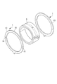
- FIG. 1 is a view illustrating the appearance of a thrust washer 1 according to an embodiment.
- the thrust washer 1 is, for example, a washer (crank washer) used together with the main bearing 5 in an automobile engine.
- the thrust washer 1 has a semi-annular washer body 11.
- the washer body 11 has a thrust surface 12 (an example of a first thrust surface) and a thrust surface 13 (an example of a second thrust surface).
- the thrust surface 12 and the thrust surface 13 are surfaces that receive a thrust load, respectively.
- the washer body 11 has a mating surface 14 and a mating surface 15.
- the mating surface 14 and the mating surface 15 are surfaces that contact or face the mating surfaces of the other thrust washers 1 when the two thrust washers 1 are used in combination.
- the washer main body 11 may be formed by any one of a single metal, an alloy, a resin, or a combination thereof as long as the properties required for the intended application of the thrust washer 1 are satisfied.
- the washer body 11 may have a single-layer structure or a multi-layer structure.
- the washer body 11 may have a structure in which metal layers of different materials or compositions are laminated (so-called bimetal), and has a structure in which a resin coating layer is formed on the metal layer. You may In one example, the thickness of the washer body 11 is 2 mm or more and 4 mm or less.
- FIG. 2 is a view showing an example in which the thrust washer 1 is used as a crank washer.
- FIG. 2 is a view as seen from a direction perpendicular to the axial direction of the crankshaft.
- the two thrust washers 1 are attached to the cylinder block (or housing) 91 and the cap 92, and the cylinder block 91 and the cap 92 are fixed by a nut 93.
- the two thrust washers 1 are distinguished from each other, the one on the cylinder block 91 side is referred to as a thrust washer 1U, and the one on the cap 92 side is referred to as a thrust washer 1L.
- the two are not distinguished, they are simply referred to as a thrust washer 1.
- the thrust surface 12 receives a thrust load from a crankshaft (not shown in FIG. 2) and is a surface (surface on the side of the paper surface of FIG. 2) that slides on the crankshaft.
- the thrust surface 13 is a surface that slides with the cylinder block 91 or the cap 92 (a surface hidden and not visible in FIG. 2).
- FIG. 3 is a schematic view illustrating the surface structure of the thrust surface 12.
- FIG. 3 (A) shows a front view seen from the axial direction of the crankshaft
- FIG. 3 (B) shows a virtual unfolded view of a cross section along line XX in FIG. 3 (A).
- the cross section in FIG. 3 (B) is a cross section parallel to the axial direction of the crankshaft, that is, a cross section parallel to the thickness direction of the thrust washer 1.
- the line XX is an arc passing through the centers of the mating surface 14 and the mating surface 15 and centered on the center C.
- the center C is the center of an arc that constitutes the outer periphery of the washer body 11.
- the thrust surface 12 has a land portion 121, a tapered portion 122, and an oil groove 123.
- the land portion 121 is a region where the height is substantially constant, that is, substantially flat.
- the height refers to the distance from the reference plane to which the position in the axial direction is fixed.
- the thrust surface 13 is a reference surface because it has no taper / land structure and is flat.
- the tapered portion 122 refers to a region where the height continuously decreases from the land portion 121 toward the oil groove 123 (note that the definition of the height here is that the thrust surface 12 side is positive and the thrust surface 13 side is negative) ).
- the oil groove 123 is a groove for holding lubricating oil.
- taper portions 122 are formed symmetrically on both sides thereof.
- the tapered portion formed on the left side of the land portion 121 in FIG. 3 is referred to as a tapered portion 122L
- the tapered portion formed on the right side of the land portion 121 is referred to as a tapered portion 122R.
- a unit structure including a set of the tapered portion 122L, the land portion 121, and the tapered portion 122R repeatedly appears in the circumferential direction (four times in the illustrated example).
- the oil grooves 123 are formed between the two unit structures (a total of three in the illustrated example).
- the boundary between the land portion 121 and the tapered portion 122 radially extends from the center C.
- the center of the circular arc that constitutes the inner periphery of the washer main body 11 is also the same as the center C.
- the boundary between the oil groove 123 and the tapered portion 122 also extends radially from the center C. This means that the boundary between the land portion 121 and the tapered portion 122 is perpendicular to the sliding direction.
- the tapered portion 122 produces an effect (wedge effect) of generating a so-called wedge film pressure in the lubricating oil present on the thrust surface 12.
- the boundary between the land portion 121 and the tapered portion 122 is not perpendicular to the sliding direction, the lubricating oil flows to lower pressure, and the wedge effect is weakened.
- the boundary between the land portion 121 and the tapered portion 122 preferably radially extends from the center C.
- the taper ratio in each unit structure is 0.4 or more and 0.9 or less, and more preferably 0.7 or more.
- the taper ratio is a ratio obtained by dividing the length of the tapered portion 122 (L1 + L3 in the figure) by the total length of the land portion 121 and the tapered portion 122 (L1 + L2 + L3 in the figure).
- the depth d of the tapered portion 122 is preferably 10 ⁇ m or more and 50 ⁇ m or less, and more preferably 30 ⁇ m or more.
- the depth of the tapered portion 122 refers to the difference between the maximum height and the minimum height of the tapered portion 122 in the XX cross section. It is preferable that the taper ratio and the depth of the tapered portion 122 be in the above range from the viewpoint of generating an appropriate wedge effect and preventing the seizing with the mating material.
- the oil groove 123 has a wide surface side (opening side) and a narrow bottom.
- the oil groove 123 in the cross section perpendicular to the radial direction (the direction in which the oil groove 123 extends), the oil groove 123 has a partial circle shape.
- the width w of the oil groove 123 on the surface is 3 mm or more and 7 mm or less in one example.
- the depth d2 of the oil groove 123 is 0.1 mm or more and 0.5 mm or less in one example.
- the cross-sectional shape of the oil groove 123 is not limited to a circle.
- the cross-sectional shape of oil groove 123 may be oval, trapezoidal, rectangular, square, or a combination thereof. Also, the oil groove 123 may be omitted.
- a relief 141 and a relief 151 are formed in the vicinity of the mating surface 14 and the mating surface 15.
- the relief 141 and the relief 151 are portions whose inner diameters are larger than the other portions, and are reliefs to prevent local contact with the crankshaft due to deformation when assembled to the cylinder block 91 or the cap 92. is there. Furthermore, the relief 141 and the relief 151 become thinner as they go to the mating surface 14 and the mating surface 15.
- the difference in thickness between the relief 141 and the relief 151 is, for example, 0.3 mm or more and 0.7 mm or less.
- the circumferential length of the relief 141 and the relief 151 is 4 mm or more and 6 mm or less in one example.
- the relief 141 and the relief 151 may be omitted.
- the thrust washer 1 has a claw (convex portion) serving as a rotation stopper for preventing the thrust washer 1 from rotating with respect to the cylinder block 91 or the cap 92. You may have.
- a relief may be formed at the base of the detent to prevent interference between the detent groove (not shown) of the cylinder block 91 or the cap 92 and the claw.
- FIG. 4 is a view illustrating the cross-sectional structure of the thrust washer 1.
- the thrust washer 1 has an undulation in the thickness direction in a state where it is not assembled to the cylinder block 91 or the cap 92, that is, in a free state.
- the term "waviness" means that the position in the thickness direction of the reference line of the washer main body 11 fluctuates in a corrugated manner according to the position in the circumferential direction.
- the amount of waviness can be quantified, for example, by placing the thrust washer 1 with the thrust surface 13 down on a flat table and measuring the level difference on the surface of the thrust surface 12 with a level difference meter in this state.
- the step on the surface of the thrust surface 12 is normalized so that the land 121 is flat.
- the difference between the highest position and the lowest position of the step on the surface of the thrust surface 12 is referred to as “the amount of wave” (the amount of wave can also be referred to as “flatness”).
- the amount of undulation is larger than the depth (height difference) d of the tapered portion (note that the depth d of the tapered portion is a value after normalization).
- the amount of undulation may be twice or more the depth d.
- the amount of undulations is 60 ⁇ m or more and 0.1 mm or less. In FIG. 4, the surface structure and the undulations are exaggerated.
- the thrust washer 1 has undulation in the free state, it is attached to the cylinder block 91 or the cap 92, and when thrust load is applied, the washer 11 main body deforms along the cylinder block 91 or the cap 92. This deformation can absorb part of the thrust load.
- the thrust washer 1 after deformation is in a non-wavy (or less) state as shown in FIG. In this state, the tapered surface / land structure as designed is formed on the thrust surface 12, and the effect of reducing the friction due to the wedge effect is exhibited.
- the thrust washer 1 can be manufactured at a lower processing cost by using pressing instead of cutting.
- the thrust washer 1 is manufactured, for example, by the following method.
- the half ring which becomes the washer main body 11 is taken out from the prepared board material. This half ring is formed, for example, by punching.
- the taper / land structure (land portion 121 and taper portion 122) provided in the washer main body 11 and the concave portion to be the oil groove 123 are formed by press processing. These taper / land structures and recesses may be formed at any timing before or after punching of the half ring.
- the thrust washer 1 can be manufactured at lower cost as compared with the example using the cutting process.
- FIG. 5 is a view illustrating the surface structure of the thrust washer 1 according to the modification.
- the tapered portions 122 are formed on both sides in the circumferential direction of the land portion 121 has been described.
- the tapered portion 122L is formed only on the upstream side (of the flow of lubricating oil) of the land portion 121.
- a taper / land structure may be formed on the thrust surface 13 in addition to or instead of the thrust surface 12. That is, a tapered portion may be formed on at least one of the thrust surface 12 and the thrust surface 13.
- the taper / land structure formed on each surface may be symmetrical with respect to the reference line in the thickness direction. It may be asymmetric.
- the specific surface structure of the thrust washer 1 is not limited to that exemplified in the embodiment.
- the number of unit structures formed on the thrust surface 12 is not limited to four.
- the number of unit structures may be 3 or less, or 5 or more.
- the thrust surface 12 may not have the land portion 121. Further, the depths of the tapered portion 122L and the tapered portion 122R may be different.
- the shape of the washer body 11 is not limited to the half ring.
- the washer body 11 may have, for example, an annular shape.
- the thrust washer 1 is not limited to one used as a crank washer of an engine.
- the thrust washer 1 may be used in devices other than the engine as long as it is used in an environment where lubricating oil is supplied.
Landscapes
- Engineering & Computer Science (AREA)
- General Engineering & Computer Science (AREA)
- Mechanical Engineering (AREA)
- Chemical & Material Sciences (AREA)
- Oil, Petroleum & Natural Gas (AREA)
- Physics & Mathematics (AREA)
- Fluid Mechanics (AREA)
- Sliding-Contact Bearings (AREA)
- Shafts, Cranks, Connecting Bars, And Related Bearings (AREA)
Abstract
一実施形態に係るスラストワッシャは、スラスト荷重を受ける第1スラスト面及び第2スラスト面を有する、環形状のワッシャ本体と、前記第1スラスト面及び前記第2スラスト面の少なくとも一方の面に形成されたテーパ部とを有し、前記ワッシャ本体は、前記スラスト面に垂直な方向において、前記テーパ部の高低差よりも大きいうねりを有する。
Description
本発明は、スラストワッシャに関する。
スラスト面にテーパ/ランド構造が形成されたスラストワッシャが知られている。例えば、特許文献1には、テーパ深さが50μm以下であり、ランド部に対するテーパ比が0.5以上0.9以下であるワッシャが記載されている。
特許文献1に記載のワッシャにおいては厳しい寸法精度が要求されることがあり、この要求を満足するためには加工コストが高くなってしまうという問題があった。
これに対し本発明は、テーパ部を有し、かつより低い加工コストで製造できるスラストワッシャを提供する。
本発明は、スラスト荷重を受ける第1スラスト面及び第2スラスト面を有する、環形状のワッシャ本体と、前記第1スラスト面及び前記第2スラスト面の少なくとも一方の面に形成されたテーパ部とを有し、前記ワッシャ本体は、前記第1スラスト面又は前記第2スラスト面に垂直な方向において、前記テーパ部の高低差よりも大きいうねりを有するスラストワッシャを提供する。
前記少なくとも一方の面は、前記環形状の周方向において前記テーパ部と隣り合うランド部を有してもよい。
前記ランド部の、前記周方向の両側に前記テーパ部が形成されてもよい。
本発明によれば、テーパ部を有するスラストワッシャをより低い加工コストで製造することができる。
1…スラストワッシャ、11…ワッシャ本体、12…スラスト面、13…スラスト面、14…合せ面、15…合せ面、91…シリンダブロック、92…キャップ、93…ナット、121…ランド部、122…テーパ部、123…油溝、141…リリーフ、151…リリーフ
図1は、一実施形態に係るスラストワッシャ1の外観を例示する図である。スラストワッシャ1は、例えば、自動車のエンジンにおいて主軸受5とともに用いられるワッシャ(クランクワッシャ)である。スラストワッシャ1は、半環形状のワッシャ本体11を有する。ワッシャ本体11は、スラスト面12(第1スラスト面の一例)及びスラスト面13(第2スラスト面の一例)を有する。スラスト面12及びスラスト面13は、それぞれ、スラスト荷重を受ける面である。さらに、ワッシャ本体11は、合せ面14及び合せ面15を有する。合せ面14及び合せ面15は、2つのスラストワッシャ1を組み合わせて用いる際に、他のスラストワッシャ1の合せ面と接触又は対向する面である。
ワッシャ本体11は、スラストワッシャ1の想定される用途において要求される特性を満たすものであれば、単体金属、合金、又は樹脂、若しくはこれらの組み合わせのうち、いずれによって形成されてもよい。ワッシャ本体11は、単層構造を有してもよく、複層構造を有してもよい。複層構造を有する場合、ワッシャ本体11は、異なる材料又は組成の金属層が積層された構造を有してもよく(いわゆるバイメタル)、金属層の上に樹脂コーティング層が形成された構造を有してもよい。一例において、ワッシャ本体11の厚さは、2mm以上4mm以下である。
図2は、スラストワッシャ1をクランクワッシャとして用いる例を示す図である。図2は、クランクシャフトの軸方向に垂直な方向から見た図である。2つのスラストワッシャ1が、シリンダブロック(又はハウジング)91及びキャップ92に装着されるシリンダブロック91及びキャップ92は、ナット93により固定されている。2つのスラストワッシャ1を互いに区別するときは、シリンダブロック91側のものをスラストワッシャ1Uといい、キャップ92側のものをスラストワッシャ1Lという。両者を区別しないときは単にスラストワッシャ1という。
スラスト面12は、クランクシャフト(図2では図示略)からスラスト荷重を受け、クランクシャフトと摺動する面(図2の紙面側の面)である。スラスト面13は、シリンダブロック91又はキャップ92と摺動する面(図2では隠れて見えない面)である。
図3は、スラスト面12の表面構造を例示する模式図である。図3(A)はクランクシャフトの軸方向から見た正面図を、図3(B)は図3(A)の線X-Xに沿った断面の仮想的な展開図を、それぞれ示している。図3(B)の断面は、クランクシャフトの軸方向に平行な断面、すなわちスラストワッシャ1の厚さ方向に平行な断面である。線X-Xは、合せ面14及び合せ面15の中心を通り、かつ中心Cを中心とする円弧である。中心Cは、ワッシャ本体11の外周を構成する円弧の中心である。
スラスト面12は、ランド部121、テーパ部122、及び油溝123を有する。ランド部121は、高さがほぼ一定、すなわちほぼ平坦な領域をいう。なおここで高さとは、軸方向における位置が固定された基準面からの距離をいう。この例においてはスラスト面13にはテーパ/ランド構造が形成されておらず平坦であるので、スラスト面13が基準面である。テーパ部122は、ランド部121から油溝123に向かって高さが連続的に減少する領域をいう(なおここでの高さの定義は、スラスト面12側が正、スラスト面13側が負である)。油溝123は、潤滑油を保持するための溝である。この例において、ランド部121を基準とすると、その両側には対称にテーパ部122が形成される。図3においてランド部121の左隣に形成されるテーパ部をテーパ部122Lといい、ランド部121の右隣に形成されるテーパ部をテーパ部122Rという。
この例においては、テーパ部122L、ランド部121、及びテーパ部122Rの組からなる単位構造が、周方向において繰り返し(図の例では4回)出現する。油溝123は、2つの単位構造の間に(図の例では合計3本)形成される。ランド部121とテーパ部122との境界は、中心Cから放射状に延びる。なお、ワッシャ本体11の内周を構成する円弧の中心も、中心Cと同一である。同様に、油溝123とテーパ部122との境界も、中心Cから放射状に延びる。これはすなわち、ランド部121とテーパ部122との境界が、摺動方向に対して垂直であることを意味する。テーパ部122は、スラスト面12上に存在する潤滑油にいわゆるくさび膜圧力を発生させる効果(くさび効果)を生じる。しかし、ランド部121とテーパ部122との境界が摺動方向に対して垂直ではないと、潤滑油が圧力の低い方に流れてしまい、くさび効果が弱まってしまう。くさび効果を高める観点から、ランド部121とテーパ部122との境界は、中心Cから放射状に延びることが好ましい。
一例において、各単位構造におけるテーパ比は、0.4以上0.9以下であり、0.7以上であることがより好ましい。テーパ比とは、テーパ部122の長さ(図ではL1+L3)を、ランド部121及びテーパ部122の合計長さ(図ではL1+L2+L3)で除した比率をいう。また、一例において、テーパ部122の深さdは、10μm以上50μm以下であることが好ましく、30μm以上であることがより好ましい。テーパ部122の深さとは、X-X断面におけるテーパ部122の最大高さと最小高さの差をいう。適切なくさび効果を発生させ、相手材との焼付きを防止する観点から、テーパ比及びテーパ部122の深さは上記の範囲にあることが好ましい。
油溝123は、表面側(開口側)が広く、底部が狭い形状を有する。図3の例では、径方向(油溝123が延びる方向)に垂直な断面において、油溝123は円の一部の形状を有する。表面における油溝123の幅wは、一例において3mm以上7mm以下である。油溝123の深さd2は、一例において0.1mm以上0.5mm以下である。なお、油溝123の断面形状は円に限定されない。油溝123の断面形状は、楕円、台形、長方形、正方形、又はこれらの組み合わせであってもよい。また、油溝123は省略されてもよい。
合せ面14及び合せ面15の近傍には、リリーフ141及びリリーフ151が形成される。リリーフ141及びリリーフ151は、他の部分よりも内径が広くなっている部分であり、シリンダブロック91又はキャップ92に組み付けたときの変形によりクランクシャフトと局部当たりが起こることを防止するための逃がしである。さらに、リリーフ141及びリリーフ151は、その厚さが合せ面14及び合せ面15に向かうにつれ薄くなる。リリーフ141及びリリーフ151の厚さの差は、一例において0.3mm以上0.7mm以下である。リリーフ141及びリリーフ151の周方向の長さは、一例において4mm以上6mm以下である。なお、リリーフ141及びリリーフ151は省略されてもよい。
図3の例においては図示を省略したものの、スラストワッシャ1は、シリンダブロック91又はキャップ92に対してスラストワッシャ1が回転してしまうことを防止するための回り止めとなる爪(凸部)を有してもよい。この場合において、回り止めの根元に、シリンダブロック91又はキャップ92の回り止め溝(図示略)と爪との干渉を防止するためのリリーフ(逃がし)が形成されてもよい。
図4は、スラストワッシャ1の断面構造を例示する図である。図3(B)においては図示を省略したものの、スラストワッシャ1は、シリンダブロック91又はキャップ92に組み付けない状態すなわち自由状態において、厚さ方向にうねりを有する。ここで、うねりとは、ワッシャ本体11の基準線の、厚さ方向の位置が、周方向の位置に応じて波打つように変動することをいう。うねりの量は、例えば、平坦な台の上にスラスト面13を下にしてスラストワッシャ1を置き、この状態で段差計によりスラスト面12の表面の段差を計測することにより定量化できる。一例において、スラスト面12の表面の段差は、ランド部121が平坦となるように規格化される。規格化された後において、スラスト面12の表面の段差の最高位置と最低位置との差を「うねり量」という(うねり量は「平面度」ということもできる)。うねり量は、テーパ部の深さ(高低差)dよりも大きい(なおテーパ部の深さdは、規格化後の値である)。うねり量は、深さdの2倍以上であってもよい。一例において、うねり量は60μm以上0.1mm以下である。なお図4では、表面構造及びうねりを誇張して図示している。
スラストワッシャ1は自由状態においてはうねりを有するものの、シリンダブロック91又はキャップ92に取り付けられ、スラスト荷重がかかると、ワッシャ11本体がシリンダブロック91又はキャップ92にならって変形する。この変形によってスラスト荷重の一部を吸収することができる。変形後のスラストワッシャ1は、図3で示したような、うねりの無い(又は少ない)状態である。この状態において、スラスト面12には設計どおりのテーパ/ランド構造が形成され、くさび効果によるフリクションの低減効果が発揮される。
このうねりは、後述するようにプレス加工を用いた製造工程に起因するものである。自由状態でうねりがあったとしても、ハウジングに組み付けて使用状態に置いたときにくさび効果を発揮できるのであれば、自由状態での寸法精度はそこまで要求されない(テーパ深さの設計値よりも平面度が悪くてもよい)。テーパ/ランド構造の寸法精度は、例えばランド部121におけるワッシャ本体11の肉厚とテーパ部122におけるワッシャ本体11の肉厚(の最小値)との差によって保証される。本実施形態によれば、切削加工ではなくプレス加工を用いることにより、より低い加工コストでスラストワッシャ1を製造することができる。
例えば本願発明者らの実験によれば、0.1mm程度のうねり量があるスラストワッシャ1でも、500乃至2000Nのスラスト荷重をかけた試験において、うねりの頂点部だけが局所的に摩耗するような現象は観測されず、スラスト面12の全体にわたってくさび効果が生じていることが示された。
スラストワッシャ1は、例えば以下の方法で製造される。準備された板材からワッシャ本体11となる半環が取り出される。この半環は例えば打ち抜き加工により形成される。ワッシャ本体11に設けられるテーパ/ランド構造(ランド部121及びテーパ部122)及び油溝123となる凹部は、プレス加工により形成される。これらのテーパ/ランド構造及び凹部は、半環の打ち抜き加工の前後いずれのタイミングで形成されてもよい。
スラストワッシャ1の加工において、切削加工ではなくプレス加工を用いることにより、切削加工を用いる例と比較してより低コストでスラストワッシャ1を製造することができる。
本発明は上述の実施形態に限定されるものではなく、種々の変形実施が可能である。以下、変形例を説明する。以下の変形例のうち2つ以上のものが組み合わせて用いられてもよい。
図5は、変形例に係るスラストワッシャ1の表面構造を例示する図である。実施形態においては、ランド部121の周方向の両側にテーパ部122が形成される例を説明した。しかし、この例においては、ランド部121の(潤滑油の流れの)上流側にのみテーパ部122Lが形成される。
実施形態においてはスラスト面12にのみテーパ/ランド構造が形成され、スラスト面13にはテーパ/ランド構造が形成されない例を説明した。しかし、スラスト面12に加え、又は代えてスラスト面13にテーパ/ランド構造が形成されてもよい。すなわち、スラスト面12及びスラスト面13の少なくとも一方の面にテーパ部が形成されてもよい。スラスト面12及びスラスト面13の双方にテーパ/ランド構造が形成される場合において、それぞれの面に形成されるテーパ/ランド構造は、厚さ方向の基準線に対して対称であってもよいし、非対称であってもよい。
スラストワッシャ1の具体的な表面構造は、実施形態において例示したものに限定されない。例えば、スラスト面12に形成される単位構造の数は4個に限定されない。単位構造の数は、3個以下であってもよいし、5個以上であってもよい。スラスト面12はランド部121を有していなくてもよい。また、テーパ部122L及びテーパ部122Rの深さが異なっていてもよい。
ワッシャ本体11の形状は半環に限定されない。ワッシャ本体11は、例えば環形状を有してもよい。
スラストワッシャ1はエンジンのクランクワッシャとして用いられるものに限定されない。潤滑油が供給される環境において用いられるものであれば、エンジン以外の装置においてスラストワッシャ1が用いられてもよい。
なお実施形態において例示した寸法の数値はあくまで例示であり、本願発明はこれに限定されるものではない。
Claims (3)
- スラスト荷重を受ける第1スラスト面及び第2スラスト面を有する、環形状のワッシャ本体と、
前記第1スラスト面及び前記第2スラスト面の少なくとも一方の面に形成されたテーパ部と
を有し、
前記ワッシャ本体は、前記第1スラスト面又は前記第2スラスト面に垂直な方向において、前記テーパ部の高低差よりも大きいうねりを有する
スラストワッシャ。 - 前記少なくとも一方の面は、前記環形状の周方向において前記テーパ部と隣り合うランド部を有する
請求項1に記載のスラストワッシャ。 - 前記ランド部の、前記周方向の両側に前記テーパ部が形成される
請求項2に記載のスラストワッシャ。
Priority Applications (3)
| Application Number | Priority Date | Filing Date | Title |
|---|---|---|---|
| CN201880058044.6A CN111108297B (zh) | 2017-11-30 | 2018-08-30 | 止推垫圈 |
| DE112018004040.2T DE112018004040T5 (de) | 2017-11-30 | 2018-08-30 | Druckscheibe |
| US16/639,067 US11168736B2 (en) | 2017-11-30 | 2018-08-30 | Thrust washer |
Applications Claiming Priority (2)
| Application Number | Priority Date | Filing Date | Title |
|---|---|---|---|
| JP2017-230202 | 2017-11-30 | ||
| JP2017230202A JP6767349B2 (ja) | 2017-11-30 | 2017-11-30 | スラストワッシャ |
Publications (1)
| Publication Number | Publication Date |
|---|---|
| WO2019106901A1 true WO2019106901A1 (ja) | 2019-06-06 |
Family
ID=66663884
Family Applications (1)
| Application Number | Title | Priority Date | Filing Date |
|---|---|---|---|
| PCT/JP2018/032123 Ceased WO2019106901A1 (ja) | 2017-11-30 | 2018-08-30 | スラストワッシャ |
Country Status (5)
| Country | Link |
|---|---|
| US (1) | US11168736B2 (ja) |
| JP (1) | JP6767349B2 (ja) |
| CN (1) | CN111108297B (ja) |
| DE (1) | DE112018004040T5 (ja) |
| WO (1) | WO2019106901A1 (ja) |
Families Citing this family (3)
| Publication number | Priority date | Publication date | Assignee | Title |
|---|---|---|---|---|
| US11111958B1 (en) * | 2020-03-03 | 2021-09-07 | Schaeffler Technologies AG & Co. KG | Hydrodynamic bearing |
| JP7848096B2 (ja) * | 2022-09-27 | 2026-04-20 | 大同メタル工業株式会社 | 半割スラスト軸受 |
| JP7480373B1 (ja) * | 2023-01-31 | 2024-05-09 | 大同メタル工業株式会社 | 半割スラスト軸受 |
Citations (8)
| Publication number | Priority date | Publication date | Assignee | Title |
|---|---|---|---|---|
| JPH07119737A (ja) * | 1993-10-28 | 1995-05-09 | Ntn Corp | 軸受装置 |
| JPH1068413A (ja) * | 1996-08-27 | 1998-03-10 | Ntn Corp | 摺動部材 |
| JPH11201145A (ja) * | 1998-01-12 | 1999-07-27 | Daido Metal Co Ltd | 半割スラスト軸受 |
| JP2003287055A (ja) * | 2002-03-29 | 2003-10-10 | Koyo Seiko Co Ltd | 十字軸用ころ軸受およびそれに用いるスラストワッシャ |
| JP2003334602A (ja) * | 2002-04-11 | 2003-11-25 | Morgan Construction Co | スリーブベアリングおよびスラストリング組立体を用いた装置 |
| JP2004036790A (ja) * | 2002-07-04 | 2004-02-05 | Shimadzu Corp | スラスト動圧ガス軸受 |
| JP2008128318A (ja) * | 2006-11-20 | 2008-06-05 | Nok Corp | スラスト軸受構造 |
| JP2008133904A (ja) * | 2006-11-28 | 2008-06-12 | Nok Corp | 樹脂製スラスト軸受 |
Family Cites Families (13)
| Publication number | Priority date | Publication date | Assignee | Title |
|---|---|---|---|---|
| FR1452868A (fr) | 1965-08-04 | 1966-04-15 | Metallurgie Francaise | Butée autolubrifiante |
| US3786289A (en) * | 1972-06-19 | 1974-01-15 | Gen Electric | Rotating machines having end thrust cushioning arrangements |
| US6511226B2 (en) * | 2000-09-05 | 2003-01-28 | Federal-Mogul World Wide, Inc. | Aluminum thrust washer |
| US6481895B2 (en) * | 2001-01-16 | 2002-11-19 | Federal-Mogul World Wide, Inc. | Flange bearing |
| US7134793B2 (en) * | 2004-08-11 | 2006-11-14 | Federal-Mogul Worldwide, Inc. | Thrust bearing assembly |
| JP2014040899A (ja) | 2012-08-23 | 2014-03-06 | Taiho Kogyo Co Ltd | テーパランド軸受 |
| GB2508914A (en) * | 2012-12-14 | 2014-06-18 | Mahle Int Gmbh | A thrust washer for a sliding bearing |
| GB2508915A (en) * | 2012-12-14 | 2014-06-18 | Mahle Int Gmbh | A thrust washer for a sliding bearing |
| GB2516294A (en) * | 2013-07-18 | 2015-01-21 | Mahle Engine Systems Uk Ltd | Thrust washer |
| BR102015005671B1 (pt) * | 2015-03-13 | 2022-05-17 | Mahle Metal Leve S/A | Arruela de encosto |
| JP6193316B2 (ja) * | 2015-08-26 | 2017-09-06 | 大同メタル工業株式会社 | 内燃機関のクランク軸用スラスト軸受及び軸受装置 |
| JP6692670B2 (ja) * | 2016-03-29 | 2020-05-13 | 大豊工業株式会社 | ワッシャ |
| WO2017170544A1 (ja) * | 2016-03-29 | 2017-10-05 | 大豊工業株式会社 | ワッシャ |
-
2017
- 2017-11-30 JP JP2017230202A patent/JP6767349B2/ja not_active Expired - Fee Related
-
2018
- 2018-08-30 DE DE112018004040.2T patent/DE112018004040T5/de not_active Withdrawn
- 2018-08-30 US US16/639,067 patent/US11168736B2/en not_active Expired - Fee Related
- 2018-08-30 CN CN201880058044.6A patent/CN111108297B/zh not_active Expired - Fee Related
- 2018-08-30 WO PCT/JP2018/032123 patent/WO2019106901A1/ja not_active Ceased
Patent Citations (8)
| Publication number | Priority date | Publication date | Assignee | Title |
|---|---|---|---|---|
| JPH07119737A (ja) * | 1993-10-28 | 1995-05-09 | Ntn Corp | 軸受装置 |
| JPH1068413A (ja) * | 1996-08-27 | 1998-03-10 | Ntn Corp | 摺動部材 |
| JPH11201145A (ja) * | 1998-01-12 | 1999-07-27 | Daido Metal Co Ltd | 半割スラスト軸受 |
| JP2003287055A (ja) * | 2002-03-29 | 2003-10-10 | Koyo Seiko Co Ltd | 十字軸用ころ軸受およびそれに用いるスラストワッシャ |
| JP2003334602A (ja) * | 2002-04-11 | 2003-11-25 | Morgan Construction Co | スリーブベアリングおよびスラストリング組立体を用いた装置 |
| JP2004036790A (ja) * | 2002-07-04 | 2004-02-05 | Shimadzu Corp | スラスト動圧ガス軸受 |
| JP2008128318A (ja) * | 2006-11-20 | 2008-06-05 | Nok Corp | スラスト軸受構造 |
| JP2008133904A (ja) * | 2006-11-28 | 2008-06-12 | Nok Corp | 樹脂製スラスト軸受 |
Also Published As
| Publication number | Publication date |
|---|---|
| DE112018004040T5 (de) | 2020-05-14 |
| JP2019100404A (ja) | 2019-06-24 |
| US20200200218A1 (en) | 2020-06-25 |
| US11168736B2 (en) | 2021-11-09 |
| JP6767349B2 (ja) | 2020-10-14 |
| CN111108297A (zh) | 2020-05-05 |
| CN111108297B (zh) | 2021-05-11 |
Similar Documents
| Publication | Publication Date | Title |
|---|---|---|
| US6634791B2 (en) | Shaft bearing member | |
| US9188159B2 (en) | Half thrust bearing and bearing device | |
| WO2019106901A1 (ja) | スラストワッシャ | |
| WO2015111707A1 (ja) | シールリング | |
| JP2012149755A (ja) | 転がり軸受用保持器 | |
| KR20180135417A (ko) | 하프 스러스트 베어링 | |
| JPWO2016113923A1 (ja) | 密封構造 | |
| JP6473335B2 (ja) | ピストンリング | |
| JP2014159861A (ja) | すべり軸受、及び、すべり軸受の製造方法 | |
| JP6529549B2 (ja) | 半割軸受およびすべり軸受 | |
| JP5089572B2 (ja) | 内燃機関のクランク軸用分割型すべり軸受および分割型すべり軸受装置 | |
| CN106594058A (zh) | 流体动压轴承 | |
| JP5801753B2 (ja) | 半割軸受及びすべり軸受 | |
| JP2019203559A (ja) | 半割軸受およびすべり軸受 | |
| JP2017180589A (ja) | ワッシャ | |
| JP6051790B2 (ja) | 内燃機関のピストン | |
| JP2014126096A (ja) | 半割スラスト軸受 | |
| JP6536774B2 (ja) | すべり軸受 | |
| JP7722221B2 (ja) | 往復移動ユニット | |
| JP5122907B2 (ja) | 密封装置 | |
| JP2016161016A (ja) | すべり軸受の製造方法及びすべり軸受 | |
| JP6692670B2 (ja) | ワッシャ | |
| JP2017180584A (ja) | ワッシャ | |
| JP7848096B2 (ja) | 半割スラスト軸受 | |
| JP2019060500A (ja) | 軸受 |
Legal Events
| Date | Code | Title | Description |
|---|---|---|---|
| 121 | Ep: the epo has been informed by wipo that ep was designated in this application |
Ref document number: 18882307 Country of ref document: EP Kind code of ref document: A1 |
|
| 122 | Ep: pct application non-entry in european phase |
Ref document number: 18882307 Country of ref document: EP Kind code of ref document: A1 |