WO2019097994A1 - 酸性ガス分離膜シート及びその製造方法 - Google Patents
酸性ガス分離膜シート及びその製造方法 Download PDFInfo
- Publication number
- WO2019097994A1 WO2019097994A1 PCT/JP2018/040089 JP2018040089W WO2019097994A1 WO 2019097994 A1 WO2019097994 A1 WO 2019097994A1 JP 2018040089 W JP2018040089 W JP 2018040089W WO 2019097994 A1 WO2019097994 A1 WO 2019097994A1
- Authority
- WO
- WIPO (PCT)
- Prior art keywords
- separation membrane
- gas separation
- layer
- hydrophilic resin
- membrane sheet
- Prior art date
- Legal status (The legal status is an assumption and is not a legal conclusion. Google has not performed a legal analysis and makes no representation as to the accuracy of the status listed.)
- Ceased
Links
Images


Classifications
-
- B—PERFORMING OPERATIONS; TRANSPORTING
- B01—PHYSICAL OR CHEMICAL PROCESSES OR APPARATUS IN GENERAL
- B01D—SEPARATION
- B01D53/00—Separation of gases or vapours; Recovering vapours of volatile solvents from gases; Chemical or biological purification of waste gases, e.g. engine exhaust gases, smoke, fumes, flue gases, aerosols
- B01D53/22—Separation of gases or vapours; Recovering vapours of volatile solvents from gases; Chemical or biological purification of waste gases, e.g. engine exhaust gases, smoke, fumes, flue gases, aerosols by diffusion
- B01D53/228—Separation of gases or vapours; Recovering vapours of volatile solvents from gases; Chemical or biological purification of waste gases, e.g. engine exhaust gases, smoke, fumes, flue gases, aerosols by diffusion characterised by specific membranes
-
- B—PERFORMING OPERATIONS; TRANSPORTING
- B01—PHYSICAL OR CHEMICAL PROCESSES OR APPARATUS IN GENERAL
- B01D—SEPARATION
- B01D63/00—Apparatus in general for separation processes using semi-permeable membranes
- B01D63/10—Spiral-wound membrane modules
- B01D63/107—Specific properties of the central tube or the permeate channel
-
- B—PERFORMING OPERATIONS; TRANSPORTING
- B01—PHYSICAL OR CHEMICAL PROCESSES OR APPARATUS IN GENERAL
- B01D—SEPARATION
- B01D67/00—Processes specially adapted for manufacturing semi-permeable membranes for separation processes or apparatus
- B01D67/0081—After-treatment of organic or inorganic membranes
- B01D67/0095—Drying
-
- B—PERFORMING OPERATIONS; TRANSPORTING
- B01—PHYSICAL OR CHEMICAL PROCESSES OR APPARATUS IN GENERAL
- B01D—SEPARATION
- B01D69/00—Semi-permeable membranes for separation processes or apparatus characterised by their form, structure or properties; Manufacturing processes specially adapted therefor
- B01D69/02—Semi-permeable membranes for separation processes or apparatus characterised by their form, structure or properties; Manufacturing processes specially adapted therefor characterised by their properties
-
- B—PERFORMING OPERATIONS; TRANSPORTING
- B01—PHYSICAL OR CHEMICAL PROCESSES OR APPARATUS IN GENERAL
- B01D—SEPARATION
- B01D69/00—Semi-permeable membranes for separation processes or apparatus characterised by their form, structure or properties; Manufacturing processes specially adapted therefor
- B01D69/12—Composite membranes; Ultra-thin membranes
- B01D69/1213—Laminated layers
-
- B—PERFORMING OPERATIONS; TRANSPORTING
- B01—PHYSICAL OR CHEMICAL PROCESSES OR APPARATUS IN GENERAL
- B01D—SEPARATION
- B01D69/00—Semi-permeable membranes for separation processes or apparatus characterised by their form, structure or properties; Manufacturing processes specially adapted therefor
- B01D69/12—Composite membranes; Ultra-thin membranes
- B01D69/1214—Chemically bonded layers, e.g. cross-linking
-
- B—PERFORMING OPERATIONS; TRANSPORTING
- B01—PHYSICAL OR CHEMICAL PROCESSES OR APPARATUS IN GENERAL
- B01D—SEPARATION
- B01D69/00—Semi-permeable membranes for separation processes or apparatus characterised by their form, structure or properties; Manufacturing processes specially adapted therefor
- B01D69/14—Dynamic membranes
- B01D69/141—Heterogeneous membranes, e.g. containing dispersed material; Mixed matrix membranes
- B01D69/142—Heterogeneous membranes, e.g. containing dispersed material; Mixed matrix membranes with "carriers"
-
- B—PERFORMING OPERATIONS; TRANSPORTING
- B01—PHYSICAL OR CHEMICAL PROCESSES OR APPARATUS IN GENERAL
- B01D—SEPARATION
- B01D71/00—Semi-permeable membranes for separation processes or apparatus characterised by the material; Manufacturing processes specially adapted therefor
- B01D71/06—Organic material
- B01D71/30—Polyalkenyl halides
- B01D71/32—Polyalkenyl halides containing fluorine atoms
- B01D71/36—Polytetrafluoroethene
-
- B—PERFORMING OPERATIONS; TRANSPORTING
- B01—PHYSICAL OR CHEMICAL PROCESSES OR APPARATUS IN GENERAL
- B01D—SEPARATION
- B01D71/00—Semi-permeable membranes for separation processes or apparatus characterised by the material; Manufacturing processes specially adapted therefor
- B01D71/06—Organic material
- B01D71/40—Polymers of unsaturated acids or derivatives thereof, e.g. salts, amides, imides, nitriles, anhydrides, esters
- B01D71/401—Polymers based on the polymerisation of acrylic acid, e.g. polyacrylate
-
- B—PERFORMING OPERATIONS; TRANSPORTING
- B01—PHYSICAL OR CHEMICAL PROCESSES OR APPARATUS IN GENERAL
- B01D—SEPARATION
- B01D71/00—Semi-permeable membranes for separation processes or apparatus characterised by the material; Manufacturing processes specially adapted therefor
- B01D71/06—Organic material
- B01D71/40—Polymers of unsaturated acids or derivatives thereof, e.g. salts, amides, imides, nitriles, anhydrides, esters
- B01D71/404—Polymers based on the polymerisation of crotonic acid
-
- B—PERFORMING OPERATIONS; TRANSPORTING
- B32—LAYERED PRODUCTS
- B32B—LAYERED PRODUCTS, i.e. PRODUCTS BUILT-UP OF STRATA OF FLAT OR NON-FLAT, e.g. CELLULAR OR HONEYCOMB, FORM
- B32B27/00—Layered products comprising a layer of synthetic resin
- B32B27/06—Layered products comprising a layer of synthetic resin as the main or only constituent of a layer, which is next to another layer of the same or of a different material
- B32B27/08—Layered products comprising a layer of synthetic resin as the main or only constituent of a layer, which is next to another layer of the same or of a different material of synthetic resin
-
- B—PERFORMING OPERATIONS; TRANSPORTING
- B32—LAYERED PRODUCTS
- B32B—LAYERED PRODUCTS, i.e. PRODUCTS BUILT-UP OF STRATA OF FLAT OR NON-FLAT, e.g. CELLULAR OR HONEYCOMB, FORM
- B32B27/00—Layered products comprising a layer of synthetic resin
- B32B27/32—Layered products comprising a layer of synthetic resin comprising polyolefins
- B32B27/322—Layered products comprising a layer of synthetic resin comprising polyolefins comprising halogenated polyolefins, e.g. PTFE
-
- B—PERFORMING OPERATIONS; TRANSPORTING
- B32—LAYERED PRODUCTS
- B32B—LAYERED PRODUCTS, i.e. PRODUCTS BUILT-UP OF STRATA OF FLAT OR NON-FLAT, e.g. CELLULAR OR HONEYCOMB, FORM
- B32B37/00—Methods or apparatus for laminating, e.g. by curing or by ultrasonic bonding
- B32B37/14—Methods or apparatus for laminating, e.g. by curing or by ultrasonic bonding characterised by the properties of the layers
- B32B37/16—Methods or apparatus for laminating, e.g. by curing or by ultrasonic bonding characterised by the properties of the layers with all layers existing as coherent layers before laminating
- B32B37/20—Methods or apparatus for laminating, e.g. by curing or by ultrasonic bonding characterised by the properties of the layers with all layers existing as coherent layers before laminating involving the assembly of continuous webs only
- B32B37/203—One or more of the layers being plastic
-
- B—PERFORMING OPERATIONS; TRANSPORTING
- B32—LAYERED PRODUCTS
- B32B—LAYERED PRODUCTS, i.e. PRODUCTS BUILT-UP OF STRATA OF FLAT OR NON-FLAT, e.g. CELLULAR OR HONEYCOMB, FORM
- B32B38/00—Ancillary operations in connection with laminating processes
- B32B38/16—Drying; Softening; Cleaning
- B32B38/164—Drying
-
- C—CHEMISTRY; METALLURGY
- C08—ORGANIC MACROMOLECULAR COMPOUNDS; THEIR PREPARATION OR CHEMICAL WORKING-UP; COMPOSITIONS BASED THEREON
- C08J—WORKING-UP; GENERAL PROCESSES OF COMPOUNDING; AFTER-TREATMENT NOT COVERED BY SUBCLASSES C08B, C08C, C08F, C08G or C08H
- C08J5/00—Manufacture of articles or shaped materials containing macromolecular substances
- C08J5/18—Manufacture of films or sheets
-
- C—CHEMISTRY; METALLURGY
- C08—ORGANIC MACROMOLECULAR COMPOUNDS; THEIR PREPARATION OR CHEMICAL WORKING-UP; COMPOSITIONS BASED THEREON
- C08J—WORKING-UP; GENERAL PROCESSES OF COMPOUNDING; AFTER-TREATMENT NOT COVERED BY SUBCLASSES C08B, C08C, C08F, C08G or C08H
- C08J7/00—Chemical treatment or coating of shaped articles made of macromolecular substances
- C08J7/04—Coating
- C08J7/0427—Coating with only one layer of a composition containing a polymer binder
-
- B—PERFORMING OPERATIONS; TRANSPORTING
- B01—PHYSICAL OR CHEMICAL PROCESSES OR APPARATUS IN GENERAL
- B01D—SEPARATION
- B01D53/00—Separation of gases or vapours; Recovering vapours of volatile solvents from gases; Chemical or biological purification of waste gases, e.g. engine exhaust gases, smoke, fumes, flue gases, aerosols
- B01D53/22—Separation of gases or vapours; Recovering vapours of volatile solvents from gases; Chemical or biological purification of waste gases, e.g. engine exhaust gases, smoke, fumes, flue gases, aerosols by diffusion
- B01D2053/221—Devices
- B01D2053/223—Devices with hollow tubes
-
- B—PERFORMING OPERATIONS; TRANSPORTING
- B01—PHYSICAL OR CHEMICAL PROCESSES OR APPARATUS IN GENERAL
- B01D—SEPARATION
- B01D2256/00—Main component in the product gas stream after treatment
- B01D2256/24—Hydrocarbons
-
- B—PERFORMING OPERATIONS; TRANSPORTING
- B01—PHYSICAL OR CHEMICAL PROCESSES OR APPARATUS IN GENERAL
- B01D—SEPARATION
- B01D2257/00—Components to be removed
- B01D2257/50—Carbon oxides
- B01D2257/504—Carbon dioxide
-
- B—PERFORMING OPERATIONS; TRANSPORTING
- B01—PHYSICAL OR CHEMICAL PROCESSES OR APPARATUS IN GENERAL
- B01D—SEPARATION
- B01D2323/00—Details relating to membrane preparation
- B01D2323/50—Control of the membrane preparation process
-
- B—PERFORMING OPERATIONS; TRANSPORTING
- B01—PHYSICAL OR CHEMICAL PROCESSES OR APPARATUS IN GENERAL
- B01D—SEPARATION
- B01D2325/00—Details relating to properties of membranes
- B01D2325/36—Hydrophilic membranes
-
- B—PERFORMING OPERATIONS; TRANSPORTING
- B01—PHYSICAL OR CHEMICAL PROCESSES OR APPARATUS IN GENERAL
- B01D—SEPARATION
- B01D2325/00—Details relating to properties of membranes
- B01D2325/38—Hydrophobic membranes
-
- B—PERFORMING OPERATIONS; TRANSPORTING
- B01—PHYSICAL OR CHEMICAL PROCESSES OR APPARATUS IN GENERAL
- B01D—SEPARATION
- B01D2325/00—Details relating to properties of membranes
- B01D2325/50—Membrane in gel form
-
- B—PERFORMING OPERATIONS; TRANSPORTING
- B32—LAYERED PRODUCTS
- B32B—LAYERED PRODUCTS, i.e. PRODUCTS BUILT-UP OF STRATA OF FLAT OR NON-FLAT, e.g. CELLULAR OR HONEYCOMB, FORM
- B32B38/00—Ancillary operations in connection with laminating processes
- B32B38/16—Drying; Softening; Cleaning
- B32B38/164—Drying
- B32B2038/166—Removing moisture
-
- B—PERFORMING OPERATIONS; TRANSPORTING
- B32—LAYERED PRODUCTS
- B32B—LAYERED PRODUCTS, i.e. PRODUCTS BUILT-UP OF STRATA OF FLAT OR NON-FLAT, e.g. CELLULAR OR HONEYCOMB, FORM
- B32B2250/00—Layers arrangement
- B32B2250/02—2 layers
-
- B—PERFORMING OPERATIONS; TRANSPORTING
- B32—LAYERED PRODUCTS
- B32B—LAYERED PRODUCTS, i.e. PRODUCTS BUILT-UP OF STRATA OF FLAT OR NON-FLAT, e.g. CELLULAR OR HONEYCOMB, FORM
- B32B2250/00—Layers arrangement
- B32B2250/24—All layers being polymeric
-
- B—PERFORMING OPERATIONS; TRANSPORTING
- B32—LAYERED PRODUCTS
- B32B—LAYERED PRODUCTS, i.e. PRODUCTS BUILT-UP OF STRATA OF FLAT OR NON-FLAT, e.g. CELLULAR OR HONEYCOMB, FORM
- B32B2255/00—Coating on the layer surface
- B32B2255/10—Coating on the layer surface on synthetic resin layer or on natural or synthetic rubber layer
-
- B—PERFORMING OPERATIONS; TRANSPORTING
- B32—LAYERED PRODUCTS
- B32B—LAYERED PRODUCTS, i.e. PRODUCTS BUILT-UP OF STRATA OF FLAT OR NON-FLAT, e.g. CELLULAR OR HONEYCOMB, FORM
- B32B2255/00—Coating on the layer surface
- B32B2255/26—Polymeric coating
-
- B—PERFORMING OPERATIONS; TRANSPORTING
- B32—LAYERED PRODUCTS
- B32B—LAYERED PRODUCTS, i.e. PRODUCTS BUILT-UP OF STRATA OF FLAT OR NON-FLAT, e.g. CELLULAR OR HONEYCOMB, FORM
- B32B2305/00—Condition, form or state of the layers or laminate
- B32B2305/02—Cellular or porous
- B32B2305/026—Porous
-
- B—PERFORMING OPERATIONS; TRANSPORTING
- B32—LAYERED PRODUCTS
- B32B—LAYERED PRODUCTS, i.e. PRODUCTS BUILT-UP OF STRATA OF FLAT OR NON-FLAT, e.g. CELLULAR OR HONEYCOMB, FORM
- B32B2307/00—Properties of the layers or laminate
- B32B2307/70—Other properties
- B32B2307/724—Permeability to gases, adsorption
-
- B—PERFORMING OPERATIONS; TRANSPORTING
- B32—LAYERED PRODUCTS
- B32B—LAYERED PRODUCTS, i.e. PRODUCTS BUILT-UP OF STRATA OF FLAT OR NON-FLAT, e.g. CELLULAR OR HONEYCOMB, FORM
- B32B2307/00—Properties of the layers or laminate
- B32B2307/70—Other properties
- B32B2307/728—Hydrophilic
-
- B—PERFORMING OPERATIONS; TRANSPORTING
- B32—LAYERED PRODUCTS
- B32B—LAYERED PRODUCTS, i.e. PRODUCTS BUILT-UP OF STRATA OF FLAT OR NON-FLAT, e.g. CELLULAR OR HONEYCOMB, FORM
- B32B2307/00—Properties of the layers or laminate
- B32B2307/70—Other properties
- B32B2307/73—Hydrophobic
-
- B—PERFORMING OPERATIONS; TRANSPORTING
- B32—LAYERED PRODUCTS
- B32B—LAYERED PRODUCTS, i.e. PRODUCTS BUILT-UP OF STRATA OF FLAT OR NON-FLAT, e.g. CELLULAR OR HONEYCOMB, FORM
- B32B2309/00—Parameters for the laminating or treatment process; Apparatus details
- B32B2309/60—In a particular environment
-
- B—PERFORMING OPERATIONS; TRANSPORTING
- B32—LAYERED PRODUCTS
- B32B—LAYERED PRODUCTS, i.e. PRODUCTS BUILT-UP OF STRATA OF FLAT OR NON-FLAT, e.g. CELLULAR OR HONEYCOMB, FORM
- B32B2327/00—Polyvinylhalogenides
- B32B2327/12—Polyvinylhalogenides containing fluorine
- B32B2327/18—PTFE, i.e. polytetrafluoroethylene
-
- B—PERFORMING OPERATIONS; TRANSPORTING
- B32—LAYERED PRODUCTS
- B32B—LAYERED PRODUCTS, i.e. PRODUCTS BUILT-UP OF STRATA OF FLAT OR NON-FLAT, e.g. CELLULAR OR HONEYCOMB, FORM
- B32B2333/00—Polymers of unsaturated acids or derivatives thereof
- B32B2333/04—Polymers of esters
-
- C—CHEMISTRY; METALLURGY
- C08—ORGANIC MACROMOLECULAR COMPOUNDS; THEIR PREPARATION OR CHEMICAL WORKING-UP; COMPOSITIONS BASED THEREON
- C08J—WORKING-UP; GENERAL PROCESSES OF COMPOUNDING; AFTER-TREATMENT NOT COVERED BY SUBCLASSES C08B, C08C, C08F, C08G or C08H
- C08J2327/00—Characterised by the use of homopolymers or copolymers of compounds having one or more unsaturated aliphatic radicals, each having only one carbon-to-carbon double bond, and at least one being terminated by a halogen; Derivatives of such polymers
- C08J2327/02—Characterised by the use of homopolymers or copolymers of compounds having one or more unsaturated aliphatic radicals, each having only one carbon-to-carbon double bond, and at least one being terminated by a halogen; Derivatives of such polymers not modified by chemical after-treatment
- C08J2327/12—Characterised by the use of homopolymers or copolymers of compounds having one or more unsaturated aliphatic radicals, each having only one carbon-to-carbon double bond, and at least one being terminated by a halogen; Derivatives of such polymers not modified by chemical after-treatment containing fluorine atoms
- C08J2327/18—Homopolymers or copolymers of tetrafluoroethylene
-
- C—CHEMISTRY; METALLURGY
- C08—ORGANIC MACROMOLECULAR COMPOUNDS; THEIR PREPARATION OR CHEMICAL WORKING-UP; COMPOSITIONS BASED THEREON
- C08J—WORKING-UP; GENERAL PROCESSES OF COMPOUNDING; AFTER-TREATMENT NOT COVERED BY SUBCLASSES C08B, C08C, C08F, C08G or C08H
- C08J2333/00—Characterised by the use of homopolymers or copolymers of compounds having one or more unsaturated aliphatic radicals, each having only one carbon-to-carbon double bond, and only one being terminated by only one carboxyl radical, or of salts, anhydrides, esters, amides, imides, or nitriles thereof; Derivatives of such polymers
- C08J2333/02—Homopolymers or copolymers of acids; Metal or ammonium salts thereof
-
- Y—GENERAL TAGGING OF NEW TECHNOLOGICAL DEVELOPMENTS; GENERAL TAGGING OF CROSS-SECTIONAL TECHNOLOGIES SPANNING OVER SEVERAL SECTIONS OF THE IPC; TECHNICAL SUBJECTS COVERED BY FORMER USPC CROSS-REFERENCE ART COLLECTIONS [XRACs] AND DIGESTS
- Y02—TECHNOLOGIES OR APPLICATIONS FOR MITIGATION OR ADAPTATION AGAINST CLIMATE CHANGE
- Y02C—CAPTURE, STORAGE, SEQUESTRATION OR DISPOSAL OF GREENHOUSE GASES [GHG]
- Y02C20/00—Capture or disposal of greenhouse gases
- Y02C20/40—Capture or disposal of greenhouse gases of CO2
Definitions
- the present invention relates to an acidic gas separation membrane sheet and a method for producing the same.
- An object of the present invention is to provide an acidic gas separation membrane sheet having excellent separation performance and a method for producing the same.
- the present invention provides an acidic gas separation membrane sheet shown below, a method for producing the same, and the like.
- An acidic gas separation membrane sheet that selectively permeates an acidic gas, wherein A first porous layer, a hydrophilic resin composition layer, and a second porous layer in this order, The second peel strength between the second porous layer and the hydrophilic resin composition layer is smaller than the first peel strength between the first porous layer and the hydrophilic resin composition layer, The acidic gas separation membrane sheet whose average value of said 2nd peeling strength is the range of 5 N / m or more and 500 N / m or less.
- the second porous layer is one selected from the group consisting of polyethylene, polypropylene, polystyrene, polyethylene terephthalate, fluorine-containing resin, polyether sulfone, polyphenylene sulfide, polysulfone, polyimide, polyether imide and polyether ether ketone
- a method for producing an acidic gas separation membrane sheet according to any one of [1] to [5], which Preparing a hydrophilic resin composition liquid for forming the hydrophilic resin composition layer; Applying the hydrophilic resin composition liquid on the first porous layer to form a liquid layer; Drying the liquid layer to form a coating layer on the first porous layer; Laminating the second porous layer on the coating layer to form a laminate;
- the step of confirming the abnormality is Imaging the liquid layer; And detecting the abnormality contained in at least one of the surface of the liquid layer and the inside of the liquid layer using the image obtained in the imaging step. Production method.
- the method further includes the step of providing a mark on at least one of the first porous layer and the second porous layer so that the region including the liquid layer in which the abnormality is detected can be recognized.
- a method for producing an acid gas separation membrane element including an acid gas separation membrane sheet The method for producing an acid gas separation membrane element, wherein the acid gas separation membrane sheet is an acid gas separation membrane sheet produced by the method for producing an acid gas separation membrane sheet according to [16].
- the acid gas separation membrane sheet of the present invention has excellent separation performance, by using the acid gas separation membrane sheet of the present invention, an acid gas separation membrane element and a separation membrane module having good separation performance can be produced. .
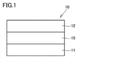
- FIG. 1 is a cross-sectional view showing an example of the acidic gas separation membrane sheet of the present invention.
- the acid gas separation membrane sheet 10 is, as shown in FIG.
- An acid gas separation membrane sheet 10 which selectively permeates an acid gas, wherein The first porous layer 11, the hydrophilic resin composition layer 15, and the second porous layer 12 in this order,
- the second peel strength between the second porous layer 12 and the hydrophilic resin composition layer 15 is smaller than the first peel strength between the first porous layer 11 and the hydrophilic resin composition layer 15,
- the average value of the second peel strengths is in the range of 5 N / m to 500 N / m.
- the average value of the second peel strength between the second porous layer 12 and the hydrophilic resin composition layer 15 is 5 N / m or more, preferably 10 N / m or more, and 25 N / m or more. Is more preferable, and usually 500 N / m or less.
- the second peel strength is in the above range, as described later, since the hydrophilic resin composition layer 15 and the second porous layer 12 are bonded with sufficient adhesive strength, the acid gas separation membrane sheet 10 is Even when wound into a roll or processed into a spiral type gas separation membrane element, it can have good separation performance in the gas membrane separation process.
- the average value of the second peel strength is a value calculated from the time-lapse data of the peel strength obtained by the peel tester. Specifically, the average value of the second peel strength is determined by measuring a 25 mm ⁇ 100 mm sample for measurement, which has been cut out of the acid gas separation membrane sheet 10, for at least 2 hours under an environment of temperature 25 ° C. and humidity 50% RH. After placing, it was attached to the peeling tester, and the time-lapse data of peeling strength measured under the condition of peeling angle 180 degree and peeling speed 300 mm / min, average peeling strength value between 5 seconds after measurement start and 15 seconds after the measurement start Value.
- the ratio (standard deviation / average value) of the standard deviation of the second peel strength between the second porous layer 12 and the hydrophilic resin composition layer 15 in the acidic gas separation membrane sheet 10 to the average value of the second peel strength is Preferably, it is less than 0.5.
- the ratio (standard deviation / average value) of the second peel strength is preferably less than 0.5, more preferably 0.2 or less, still more preferably 0.1 or less, and usually 0 Greater than.
- the smaller the ratio (standard deviation / average value) of the second peel strength indicates that the hydrophilic resin composition layer 15 and the second porous layer 12 adhere with uniform adhesive strength over the entire surface.
- an adhesion failure portion exists between the hydrophilic resin composition layer 15 and the second porous layer 12, and the hydrophilic resin composition layer It shows that the adhesive strength between the second porous layer 12 and the second porous layer 12 is not uniform.
- the ratio of the standard deviation of the second peel strength to the average value of the second peel strength is a measurement sample of size 25 mm ⁇ 100 mm cut out from the acid gas separation membrane sheet 10 at a temperature of 25 ° C. And after leaving it for 2 hours or more in the environment of humidity 50% RH, it attaches to the peeling tester and it measures 5 seconds after the measurement start about the time-lapse data of peeling strength measured under the conditions of peeling angle 180 degree and peeling speed 300mm / min.
- the acidic gas separation membrane sheet 10 may be processed into a so-called spiral shape and used for a gas separation membrane element.
- the acid gas separation membrane sheet 10 may be wound into a roll during the manufacturing process, and the acid gas separation membrane sheet 10 wound into the roll may be unwound to form a flat sheet other than the spiral type described above. It may be processed into a membrane type, pleated type, plate-and-frame type gas separation membrane element or the like.
- the acid gas separation membrane sheet 10 of the present embodiment has good separation performance in the gas membrane separation process even when the acid gas separation membrane sheet is wound into a roll or processed into a spiral type gas separation membrane element be able to.
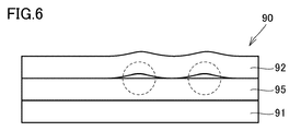
- the acid gas separation membrane sheet 90 having a second peel strength of less than 5 N / m and the above-mentioned ratio (standard deviation / average value) of the second peel strength of 0.5 or more is used for the gas membrane separation process. At that time, an acid gas separation membrane sheet having poor separation performance may be present.
- the cause is (I) In the acid gas separation membrane sheet 90 having poor separation performance, wrinkles are generated in the second porous layer 92, (Ii) In this case, when the second porous layer 92 and the hydrophilic resin composition layer 95 are not adhered with sufficient adhesive strength, and the second porous layer 92 is laminated, the hydrophilic resin composition layer The hydrophilic resin composition layer 95 and the second porous layer 92 do not adhere uniformly over the entire surface due to air bubble marks formed on the surface of the surface 95 or pores remaining inside, and a portion surrounded by a broken line in FIG.
- the adhesion failure is caused by the friction load between the sheets and the like caused by winding when it is wound into a roll or processed into a spiral type gas separation membrane element In the portion, a slip is generated between the hydrophilic resin composition layer 95 and the second porous layer 92, and wrinkles are easily generated in the second porous layer 92;
- V It is considered that depressions and holes are generated in the hydrophilic resin composition layer 95 due to the wrinkles generated in the above (iii) and (iv), and as a result, good separation performance can not be obtained in the gas membrane separation process.
- the average value of the second peel strength is less than 5 N / m, and adhesion failure is caused. It is considered that the above ratio (standard deviation / average value) of the second peel strength is 0.5 or more because it has a portion.
- the average value of the second peeling strength is 5 N / m or more, and the above ratio (standard deviation / average value) of the second peeling strength is less than 0.5. Therefore, it is thought that the hydrophilic resin composition layer 15 and the second porous layer 12 adhere uniformly over the entire surface, and the occurrence of the adhesion failure portion is suppressed.
- the acid gas separation membrane sheet 10 is provided in a gas separation membrane element described later for separating an acid gas from a source gas, and is an acid which selectively transmits the acid gas to separate the acid gas contained in the source gas. It has gas selective permeability.
- the acid gas refers to carbon dioxide (CO 2 ), hydrogen sulfide (H 2 S), carbonyl sulfide, sulfur oxides (SO x ), nitrogen oxides (NO x ), hydrogen halides such as hydrogen chloride, and the like.
- the source gas means a gas supplied to the gas separation membrane element, and the source gas contains at least an acid gas.
- the dissolution and diffusion mechanism is a mechanism that separates the acid gas using the difference in the solubility of the gas component contained in the source gas to the film material and the difference in the diffusion coefficient of the gas component contained in the source gas in the film. It is.
- the facilitated transport mechanism the acid gas contained in the raw material gas and the substance reversibly reacting with the acid gas contained in the film material (hereinafter sometimes referred to as "acid gas carrier") are produced by reaction. It is a mechanism that forms a substance to promote the permeation of acid gas.
- the acid gas is CO 2
- the acid gas carrier CO 2 carrier
- cesium carbonate Cs 2 CO 3
- the symbol “ ⁇ ” in the reaction formula (1) indicates that this reaction is a reversible reaction.
- the hydrophilic resin composition layer 15 has gas selective permeability that allows the acid gas to selectively pass through the acid gas separation membrane sheet 10.
- the hydrophilic resin composition layer 15 is a gel-like layer, and contains at least a hydrophilic resin and a substance that reversibly reacts with an acid gas (acid gas carrier).
- the hydrophilic resin composition layer 15 may contain an additive other than the hydrophilic resin and the acidic gas carrier, as necessary.
- the thickness of the hydrophilic resin composition layer 15 may be appropriately selected depending on the separation performance required for the acidic gas separation membrane sheet 10, but generally, it is preferably in the range of 0.1 ⁇ m to 600 ⁇ m, and 0.5 ⁇ m to 400 ⁇ m. Is more preferably in the range of 1 ⁇ m to 200 ⁇ m.
- the acidic gas separation membrane sheet 10 have a gel-like hydrophilic resin composition layer containing a hydrophilic resin having a hydrophilic group such as a hydroxyl group or an ion exchange group. It is more preferable to include a crosslinkable hydrophilic resin which exhibits high water retentivity by having a network structure by cross-linking of molecular chains of the hydrophilic resin. Since a pressure difference is applied to the acid gas separation membrane sheet 10 as a driving force for the acid gas to permeate through the acid gas separation membrane sheet 10, the pressure resistance is also required from the acid gas separation membrane sheet 10. It is preferable to use a hydrophilic resin containing a crosslinkable hydrophilic resin.
- the polymer forming the hydrophilic resin preferably has, for example, a structural unit derived from an acrylic acid alkyl ester, a methacrylic acid alkyl ester, a vinyl ester of a fatty acid, or a derivative thereof.
- Examples of such a polymer exhibiting hydrophilicity include polymers formed by polymerizing monomers such as acrylic acid, itaconic acid, crotonic acid, methacrylic acid and vinyl acetate, and specifically, ion exchange groups A polyacrylic acid-based resin having a carboxyl group, a polyitaconic acid-based resin, a polycrotonic acid-based resin, a polymethacrylic acid-based resin, a polyvinyl alcohol-based resin having a hydroxyl group, etc.
- Examples include polymer based resins, acrylic acid-methacrylic acid copolymer based resins, acrylic acid-methyl methacrylate copolymer based resins, and methacrylic acid-methyl methacrylate copolymer based resins.
- a polyacrylic acid resin which is a polymer of acrylic acid
- a polymethacrylic acid resin which is a polymer of methacrylic acid
- a polyvinyl alcohol resin which is obtained by hydrolyzing a polymer of vinyl acetate, methyl acrylate and vinyl acetate
- Acrylate-vinyl alcohol copolymer based resin obtained by saponifying a copolymer of acrylic acid, acrylic acid-methacrylic acid copolymer based resin which is a copolymer of acrylic acid and methacrylic acid
- polyacrylic acid, acrylic acid salt -Vinyl alcohol copolymer resin is more preferable.
- the crosslinkable hydrophilic resin may be prepared by reacting a polymer exhibiting hydrophilicity with a crosslinking agent, or a copolymer of a monomer serving as a raw material of the polymer exhibiting hydrophilicity and a crosslinkable monomer It may be prepared by The crosslinking agent or the crosslinking monomer is not particularly limited, and a conventionally known crosslinking agent or crosslinking monomer can be used.
- crosslinking agent for example, epoxy crosslinking agent, polyvalent glycidyl ether, polyhydric alcohol, polyvalent isocyanate, polyvalent aziridine, haloepoxy compound, polyvalent aldehyde, polyvalent amine, organic metal type crosslinking agent, metal type crosslinking agent, etc.
- cross-linking agents known in the art.
- examples of the crosslinking monomer include conventionally known crosslinking monomers such as divinylbenzene, N, N'-methylenebisacrylamide, trimethylolpropane triallyl ether, pentaerythritol tetraallyl ether and the like.
- crosslinking method for example, methods such as thermal crosslinking, ultraviolet crosslinking, electron beam crosslinking, radiation crosslinking, photocrosslinking, methods described in JP-A 2003-268009, JP-A 7-88171, etc. Conventionally known techniques can be used.
- a substance (acidic gas carrier) that reversibly reacts with an acidic gas is present in the hydrophilic resin composition layer 15 containing a hydrophilic resin, and is an acidic gas dissolved in water present in the hydrophilic resin composition layer 15
- the acid gas is selectively permeated by reacting reversibly with the acid.
- the hydrophilic resin composition layer 15 contains, as an acid gas carrier, at least one compound that reversibly reacts with the acid gas.
- the acidic gas carrier when the acidic gas is carbon dioxide, alkali metal carbonates, alkali metal bicarbonates, alkanolamines (for example, described in Japanese Patent No.
- alkali metal hydroxides For example, when the acid gas is a sulfur oxide, etc., as described in WO 2016/024523 etc., sulfur-containing compounds, citrates of alkali metals, and transition metal complexes (for example, JP 2879057 etc.)
- the acid gas is nitrogen oxide, alkali metal nitrites, transition metal complexes (for example, described in Japanese Patent No. 2879057) and the like can be mentioned.
- the hydrophilic resin composition layer 15 may contain, for example, an acid gas hydration reaction catalyst, a surfactant described later, and the like as an additive.
- the acid gas hydration reaction catalyst can improve the reaction rate of the acid gas and the acid gas carrier.
- an oxo acid compound is preferably contained, and an oxo acid compound of at least one element selected from the group consisting of Group 14 elements, Group 15 elements, and Group 16 elements It is more preferable to include at least one selected from the group consisting of a tellurite compound, a selenite compound, an arsenous acid compound, and an orthosilicate compound.
- the first porous layer 11 may be a layer to which the hydrophilic resin composition liquid for forming the hydrophilic resin composition layer 15 is applied, as described later.
- the first porous layer 11 is a gas component which selectively permeates the raw material gas supplied to the hydrophilic resin composition layer 15, particularly the hydrophilic resin composition layer 15 contained in the raw material gas, in the acidic gas separation membrane sheet 10. It has a high gas permeability porosity so as not to be a diffusion resistance of
- the first porous layer 11 may have a single layer structure or a laminated structure of two or more layers. It is preferable that the 1st porous layer 11 has the heat resistance according to the process conditions in which application of the acidic gas separation membrane sheet 10 is assumed.
- heat resistance means that the shape of the first porous layer 11 or the like before storage is maintained even after the member such as the first porous layer 11 is stored under the temperature condition of the process condition or more for 2 hours. It means that melting does not produce a visually identifiable curl.
- the second porous layer 12 may be a layer laminated on the exposed surface of the hydrophilic resin composition layer 15 formed on the first porous layer 11 as described later.
- the second porous layer 12 is a gas component which selectively permeates the raw material gas supplied to the hydrophilic resin composition layer 15, particularly the hydrophilic resin composition layer 15 contained in the raw material gas, in the acidic gas separation membrane sheet 10. It has a high gas permeability porosity so as not to be a diffusion resistance of
- the second porous layer 12 may have a single layer structure or a laminated structure of two or more layers. It is preferable that the 2nd porous layer 12 has the heat resistance according to the process conditions in the plant in which application of the acidic gas separation membrane sheet 10 is assumed.
- the first porous layer 11 may be hydrophobic, and the contact angle of water at a temperature of 25 ° C. may be 90 ° or more, 95 ° or more, or 100 ° or more. .
- the second porous layer 12 is preferably hydrophobic. Specifically, the contact angle of water at a temperature of 25 ° C. is preferably 90 degrees or more, more preferably 95 degrees or more, and still more preferably 100 degrees or more.
- the contact angle of water can be measured with a contact angle meter (for example, Kyowa Interface Science Co., Ltd .; trade name: “DropMaster 500”).
- the first porous layer 11 may be a layer to which a hydrophilic resin composition liquid for forming the hydrophilic resin composition layer 15 is applied as described later. In this case, a state in which a part of the resulting hydrophilic resin composition layer 15 has entered the pores of the first porous layer 11 is included.
- the second porous layer 12 may be a layer laminated on the coating layer as described later. In this case, the degree of penetration of the hydrophilic resin composition layer 15 into the pores of the second porous layer 12 is smaller than that of the first porous layer 11.
- the first porous layer 11 is a layer to which the hydrophilic resin composition liquid is applied and the second porous layer 12 is a layer to be laminated on the coating layer
- the second peel strength between the second porous layer 12 and the hydrophilic resin composition layer 15 is smaller than the first peel strength between the first porous layer 11 and the hydrophilic resin composition layer 15.
- the magnitude relationship between the first peel strength and the second peel strength can be confirmed by the measurement of the second peel strength described above. Specifically, when the second porous layer 12 of the acidic gas separation membrane sheet 10 is peeled off under a predetermined condition using a peeling tester, the hydrophilic resin composition layer 15 is present on the surface on the first porous layer 11 side. When the second peel strength is smaller than the first peel strength and the hydrophilic resin composition layer 15 is present on the surface on the second porous layer 12 side, the second peel strength is greater than the first peel strength it can.
- first porous layer 11 and the second porous layer 12 preferably contains a resin material.
- resin materials contained in the first porous layer 11 and the second porous layer 12 include polyolefin resins such as polyethylene (PE) and polypropylene (PP); polytetrafluoroethylene (PTFE), polyvinyl fluoride (PVF), Fluorine-containing resins such as polyvinylidene fluoride (PVDF); polyester resins such as polystyrene (PS), polyethylene terephthalate (PET) and polyethylene naphthalate; polyether sulfone (PES), polyphenylene sulfide (PPS), polysulfone (PSF), polyimide Examples thereof include resin materials such as (PI), polyetherimide (PEI), polyetheretherketone (PEEK), high molecular weight polyester, heat resistant polyamide, aramid, polycarbonate and the like.
- polypropylene (PP) or a fluorine-containing resin is preferable, and polypropylene (PP) or polytetrafluoroethylene (PTFE) is more preferable.
- the resin material forming the first porous layer 11 and the resin material forming the second porous layer 12 may be the same material or different materials.
- the thickness of the first porous layer 11 and the thickness of the second porous layer 12 are not particularly limited, but in view of mechanical strength, in general, the range of 10 ⁇ m to 3000 ⁇ m is preferable, the range of 10 ⁇ m to 500 ⁇ m is more preferable, and 15 ⁇ m to A range of 150 ⁇ m is more preferred.
- the thickness of the first porous layer 11 and the thickness of the second porous layer 12 may be the same as or different from each other.
- the porosity of the first porous layer 11 and the porosity of the second porous layer 12 are preferably in the range of 5% to 99%, and more preferably in the range of 30% to 90%.
- the porosity of the first porous layer 11 and the porosity of the second porous layer 12 may be the same as or different from each other.
- the acidic gas separation membrane sheet 10 is a hydrophilic resin composition of the first porous layer 11 and the second porous layer 12 for the purpose of additionally imparting strength to the first porous layer 11 and the second porous layer 12.
- a porous body may be further laminated on the side not in contact with the layer 15.
- an inorganic material such as metal, glass, ceramics, etc., a non-woven fabric or a woven fabric containing both of these materials is suitably used.
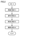
- FIG. 2 is a flow chart showing an example of the method for producing an acid gas separation membrane sheet of the present invention.
- FIG. 3 is a schematic view of a production apparatus for producing the acidic gas separation membrane sheet 10. The method for producing the acid gas separation membrane sheet 10 is, as shown in FIG.
- Preparing a hydrophilic resin composition liquid for forming the hydrophilic resin composition layer 15 (hereinafter referred to as "preparation step (S1)”); A step of applying a hydrophilic resin composition liquid on the first porous layer 11 to form a liquid layer (hereinafter referred to as “coating step (S2)”); Drying the liquid layer to form a coating layer on the first porous layer 11 (hereinafter referred to as “drying step (S3)”); And forming a laminate 18 by laminating the second porous layer 12 on the coating layer (hereinafter referred to as “lamination step (S4)”),
- the hydrophilic resin composition liquid contains a hydrophilic resin and a medium.
- the hydrophilic resin composition liquid may further contain a substance that reversibly reacts with the acid gas.
- the method for producing the acid gas separation membrane sheet 10 preferably further includes a step of drying the coated layer in the laminate 18 (hereinafter referred to as “additional drying step") subsequent to the laminating step (S4), Between the coating step (S2) and the drying step (S3), a step of confirming the abnormality of the liquid layer (hereinafter, referred to as “inspection step”) may be included.
- the process may include a process of removing a region including the liquid layer in which an abnormality is detected in the inspection process (hereinafter, referred to as “removal process”).
- the acidic gas separation membrane sheet 10 is unrolled from the first porous layer wound body 11 a in which the first porous layer 11 is wound in a roll, and the second porous layer 12 is formed into a roll.
- it is manufactured in a system.
- the preparation step (S1) is a step of preparing a hydrophilic resin composition liquid for forming the hydrophilic resin composition layer 15.
- the hydrophilic resin composition liquid may contain a hydrophilic resin and a medium, and may contain a substance reversibly reacting with an acidic gas (acidic gas carrier).
- the preparation step (S1) for example, the raw materials (hydrophilic resin, medium, etc.) for obtaining the hydrophilic resin composition liquid are mixed at a temperature at which the raw material composition does not change, for example, normal temperature (usually 20 ° C.)
- a hydrophilic resin composition liquid can be prepared.
- the hydrophilic resin composition liquid is a coating liquid for applying on the first porous layer 11 to form the hydrophilic resin composition layer 15.
- the hydrophilic resin composition liquid obtained in the preparation step (S1) can be stored in the raw material tank 31, as shown in FIG.
- the raw material tank 31 shown in FIG. 3 may be omitted, and the raw material may be charged into the stirring tank 32 and mixed to prepare the hydrophilic resin composition liquid.
- hydrophilic resin and the acidic gas carrier those described above can be used.
- the medium for example, water or a protic polar solvent such as alcohol such as methanol, ethanol, 1-propanol, 2-propanol; nonpolar solvent such as toluene, xylene, hexane or the like; acetone, methyl ethyl ketone, methyl isobutyl ketone etc Aprotic polar solvents such as ketone, N-methylpyrrolidone, N, N-dimethylacetamide, N, N-dimethylformamide and the like.
- the medium one type may be used alone, or two or more types may be used in combination as long as they are compatible with each other.
- a medium containing at least one selected from the group consisting of water or alcohols such as methanol, ethanol, 1-propanol, 2-propanol and the like is preferable, and a medium containing water is more preferable.
- a surfactant may be added to the hydrophilic resin composition liquid as necessary.
- the hydrophilic resin composition liquid is applied to the first porous layer 11 by adding a surfactant to the hydrophilic resin composition liquid, or the second porous layer 12 is laminated on the hydrophilic resin composition layer 15
- the surfactant is distributed unevenly at the interface between the hydrophilic resin composition layer 15 and the first porous layer 11 and the second porous layer 12, and the hydrophilic resin composition layer 15 and the first porous layer 11 and the second porous layer 12
- the wettability with the porous layer 12 can be improved to improve the unevenness of the film thickness and the like.
- the surfactant is not particularly limited, but, for example, polyoxyethylene polyoxypropylene glycols, polyoxyethylene alkylphenyl ethers, polyoxyethylene alkyl ethers, fluorosurfactant, silicone surfactant and the like Conventionally known surfactants can be used. One surfactant may be used alone, or two or more surfactants may be used in combination.
- the hydrophilic resin composition liquid may contain the above-described acid gas hydration reaction catalyst.
- the application step (S2) is a step of applying the hydrophilic resin composition liquid prepared in the preparation step (S1) on the first porous layer 11 to form a liquid layer on the first porous layer 11.
- the standing step (S2b) of the defoaming step described later is performed under a reduced pressure atmosphere, it is preferable to perform the coating step (S2) after releasing the pressure reduction.
- the standing step (S2b) is performed under a heated atmosphere, or in the case where the temperature control step described later is included, adjustment to an appropriate viscosity when applying the hydrophilic resin composition liquid or In order to suppress the generation of air bubbles due to the gas dissolved in the hydrophilic resin composition liquid, it is preferable to perform the coating step (S2) after adjusting the temperature of the hydrophilic resin composition liquid.
- the coating step (S2) is preferably performed at a temperature of 15 to 30 ° C. under atmospheric pressure.
- the hydrophilic resin composition liquid delivered from the defoaming tank 34 is supplied to the coating liquid tank 37 provided with the slot die 38.
- the hydrophilic resin composition liquid is continuously applied from the slot die 38 onto the first porous layer 11 continuously unwound from the first porous layer wound body 11 a in which the first porous layer 11 is wound into a roll. Apply to form a liquid layer.
- the first porous layer winding body 11a is preferably obtained by winding the first porous layer 11 having a length of 10 m or more, and the unit length of the acid gas separation membrane sheet necessary for manufacturing one gas separation membrane element More preferably, it is an integral multiple of
- FIG. 3 shows a method of applying the hydrophilic resin composition liquid using the slot die 38
- the method of applying the hydrophilic resin composition liquid to the first porous layer 11 is not limited to this.
- the coating method include spin coating, bar coating, die coating, blade coating, air knife coating, gravure coating, roll coating coating, spray coating, dip coating, comma roll method, kiss coating method, screen printing, inkjet printing and the like. be able to.
- the coating amount of the hydrophilic resin composition liquid is preferably in the range of 1 g / m 2 to 1000 g / m 2 , and in the range of 5 g / m 2 to 750 g / m 2 , in terms of the coated amount (solid content per unit area).
- Control of the coating amount is controlled by the application speed of the hydrophilic resin composition liquid (for example, the transport speed of the first porous layer 11), the concentration of the hydrophilic resin composition liquid, the discharge amount of the hydrophilic resin composition liquid, etc. be able to.
- the application of the hydrophilic resin composition liquid to the first porous layer 11 may be in the form of stripes or dots.
- the temperature of the hydrophilic resin composition liquid to be applied in the application step (S2) may be suitably determined in accordance with the composition and concentration, but if the temperature is too high, the hydrophilic resin applied to the first porous layer 11 It is preferable that the temperature is 15 ° C. or higher, because the medium may evaporate a large amount from the liquid layer of the composition liquid and the composition or concentration may change, or evaporation marks may remain in the hydrophilic resin composition layer 15. And the temperature range lower 5 degreeC or more than the boiling point of the medium currently used is preferable.
- the temperature of the hydrophilic resin composition liquid in the coating step (S2) is preferably in the range of 15 ° C. to 95 ° C., and usually in the temperature range of 15 ° C. to 30 ° C. .
- the drying step (S3) is a step of drying the liquid layer to form a coating layer on the first porous layer 11.
- the first porous layer 11 on which the liquid layer is formed by applying the hydrophilic resin composition liquid is transported to the drying furnace 39 shown in FIG. The medium is removed to form a coated layer.
- the method of removing the medium is not particularly limited, but a method of evaporating and removing the medium by ventilating heated air or the like and drying the liquid layer is preferable.
- the inside of the drying furnace 39 is adjusted to a predetermined temperature and a predetermined humidity, and the first porous layer 11 having the liquid layer formed therein is carried into the drying furnace 39, and the liquid on the first porous layer 11 is The medium may be evaporated away from the layer.
- the drying step (S3) it is preferable to select the drying conditions so that the medium content of the coating layer is suitable when the second porous layer 12 is stacked in the stacking step (S4) described later.
- the drying conditions in the drying oven 39 may be determined according to the medium content of the coating layer in the laminating step (S4), but the drying temperature in the drying oven 39 is the medium contained in the hydrophilic resin composition liquid It is preferable to determine in consideration of the type of the first porous layer 11. In general, the temperature is preferably higher than the freezing point of the medium and lower than the melting point of the material forming the first porous layer 11, and in general, the range of 60 ° C. to 200 ° C. is preferable. In addition, the drying step may be performed by dividing the inside of the drying oven 39 and setting each section to a different temperature. In this case, the temperature of the compartment of the inlet and outlet part is preferably lower than the temperature of the compartment of the central part.
- the coating step (S2) and the drying step (S3) may be repeated twice or more to form a hydrophilic resin composition layer having two or more coating layers.
- the hydrophilic resin composition layer is composed of two or more coated layers, it is possible to suppress the generation of pinholes caused by unevenness or the like of the hydrophilic resin composition layer 15.
- coating conditions and drying conditions such as composition of a hydrophilic resin composition liquid and a coating amount, may mutually differ in each coating layer, and may be the same.
- the laminating step (S4) is a step of laminating the second porous layer 12 on the coating layer formed on the first porous layer 11 in the drying step (S3) to form a laminate 18.
- the second porous layer 12 is laminated on the opposite side to the first porous layer 11 of the coating layer.
- the laminating step (S4) for example, as shown in FIG. 3, the second porous layer 12 is continuously unwound from the second porous layer wound body 12a in which the second porous layer 12 is wound into a roll, A laminate 18 is formed by laminating on the exposed surface of the coating layer formed on the porous layer 11.
- the second porous layer winding body 12 a is preferably obtained by winding the second porous layer 12 having a length of 10 m or more, and the unit length of the acid gas separation membrane sheet necessary for manufacturing one gas separation membrane element More preferably, it is an integral multiple of
- the laminating step (S4) it is preferable to laminate the second porous layer 12 on the coated layer in the range of environmental humidity of 40% RH to 85% RH.
- the environmental humidity is more preferably 45% RH or more, further preferably 50% RH or more, and usually 85% RH or less.
- a step of winding the laminate 18 in a roll may be performed to form a laminate wound body 18a.
- the inspection step is a step performed between the coating step (S2) and the drying step (S3).
- the inspection step In the inspection step, abnormalities such as foreign matter, air bubbles, air bubble marks and the like present on at least one of the liquid layer surface and the inside of the liquid layer of the hydrophilic resin composition liquid applied on the first porous layer 11 are confirmed.
- the inspection step may or may not be provided. However, by providing the inspection step, it becomes easy to grasp the region inferior to the separation performance in the laminate wound body 18a, so when the gas separation membrane element is manufactured using the acid gas separation membrane sheet 10, the separation performance Acid gas separation membrane sheet 10 can be efficiently extracted.
- a step of imaging the liquid layer formed by applying the hydrophilic resin composition liquid from the slot die 38 onto the first porous layer 11 (hereinafter referred to as “imaging step”
- the step of detecting an abnormality included in at least one of the liquid layer surface and the inside of the liquid layer using the image obtained in the imaging step (hereinafter referred to as the “abnormal detection step”), and the first porous layer.
- at least one of the second porous layers preferably include a step of applying a mark for making it possible to recognize an area including a liquid layer in which an abnormality has been detected (hereinafter referred to as a “marking step”).
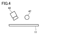
- FIG. 4 is a schematic view for explaining an imaging method in the imaging step.
- the liquid layer on the first porous layer 11 is imaged using an imaging device 42 such as a camera.
- the imaging process is preferably performed using a light source 47 that emits visible light and / or infrared light in addition to the imaging device 42.
- the light source 47 is preferably linear illumination arranged in a direction perpendicular to the transport direction of the first porous layer 11.
- the visible light and / or the infrared light emitted from the light source 47 is applied to the liquid layer on the first porous layer 11.
- the imaging device 42 performs imaging at a position where a specular reflection image of visible light and / or infrared light emitted from a light source is not incident, and reflected light or scattering caused by an abnormality present on the surface of the liquid layer and / or inside the liquid layer. It is preferred to detect light.
- the imaging device 42 performs imaging from one direction, a plurality of imaging devices may be provided to image the liquid layer on the first porous layer 11 from a plurality of directions.
- each pixel is divided into an abnormal portion and a normal portion based on whether the density value of each pixel is equal to or greater than a preset threshold value or smaller than the threshold value. It can be carried out by analysis using a binary binarization processing method.
- the marking process provides a mark for making it possible to recognize an area including the liquid layer in which an abnormality is detected in the abnormality detection process.
- the mark provided in the marking step can be provided, for example, in at least one of the first porous layer and the second porous layer in the region including the liquid layer in which the abnormality is detected, and is laminated in the laminating step (S4) It is preferable to provide on the 2 porous layer 12.
- a mark When a mark is given to the first porous layer 11 in the marking step, for example, it may be carried out following the abnormality detection step, or between the drying step (S3), the drying step (S3) and the laminating step (S4). You may carry out and you may provide to the 1st porous layer of the laminated body 18 obtained at the lamination
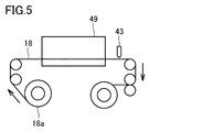
- the mark can be applied, for example, by applying an ink to the first porous layer 11 and / or the second porous layer 12 from a marking head 43 as shown in FIG.
- a mark is provided using the marking head 43, for example, in the abnormality detection step, information on the position of the area including the liquid layer in which the abnormality is detected is acquired, and the abnormality is detected based on this information.
- the first porous layer and / or the second porous layer of the area including the liquid layer in which an abnormality is detected is provided with a mark by calculating the timing when the area including the liquid layer passes through the position of the marking head 43. can do.
- the removing step the region including the liquid layer in which the abnormality is detected is removed from the laminate 18 based on the mark applied in the marking step.
- the removing step has a step of, for example, unrolling the laminated body 18 once wound into a roll, and winding the laminated body 18 from which the region including the liquid layer in which abnormality is detected is removed into a roll. Good.
- the removing step may be performed, for example, when the laminated body 18 wound in a roll shape is unwound in the production of the gas separation membrane element using the laminated body 18.
- the acidic gas separation membrane sheet 10 having no abnormality in the production of the gas separation membrane element is obtained by removing the area including the liquid layer in which the defect is detected by cutting or the like based on the mark applied in the marking step. Since it can be used, an acidic gas separation membrane element excellent in separation performance can be efficiently produced.
- the method for producing the acid gas separation membrane sheet 10 may have other steps other than the above-described steps.
- a process of adjusting the hydrophilic resin composition liquid to a predetermined temperature hereinafter referred to as "temperature control process”
- hydrophilicity A step of removing air bubbles contained in the resin composition liquid hereinafter referred to as "defoaming step”
- a step of detecting contaminants such as air bubbles and foreign matter mixed in the hydrophilic resin composition liquid hereinafter referred to as "liquid inspection And the like.
- a lamination process it is a process performed in order to further remove the medium in the application layer formed at the drying process (S3) (henceforth "the additional drying process”). Etc. can be mentioned.
- the defoaming step is performed between the preparation step (S1) and the application step (S2) in order to remove air bubbles contained in the hydrophilic resin composition liquid prepared in the preparation step (S1).
- the degassing step may or may not be provided in the method for producing the acid gas separation membrane sheet 10
- the defoaming step is performed to apply the coating step (S 2).
- Air bubbles may be mixed in the liquid layer, and the occurrence of abnormalities such as air bubble marks and pores in the hydrophilic resin composition layer 15 of the acid gas separation membrane sheet 10 can be suppressed.
- the viscosity of the hydrophilic resin composition liquid at a temperature of 25 ° C. and a shear rate of 0.1 s ⁇ 1 can be measured by a rheometer (for example, TA Instruments Ltd .; trade name: “AR2000 ex”).
- the defoaming step is a step of applying shear to the hydrophilic resin composition liquid (hereinafter referred to as "shear application step") and a step of standing the hydrophilic resin composition liquid (hereinafter referred to as “static step”). And can be included.
- the shear application step (S2a) and the standing step (S2b) are preferably repeated once or twice or more. Moreover, it is preferable that a degassing process performs a stationary process (S2b) at the end. Thereby, the defoaming of the hydrophilic resin composition liquid can be sufficiently performed.
- the shear application step (S2a) is not particularly limited as long as it is a step of applying shear to the hydrophilic resin composition liquid, but a stirring step of stirring the hydrophilic resin composition liquid, passing the hydrophilic resin composition liquid through a filter A filtration process etc. can be mentioned, It is preferable that it is at least one among a stirring process and a filtration process. In the shear application step, it is more preferable to perform both the stirring step and the filtration step. In this case, it is preferable to perform the stirring step first and then the filtration step.
- the stirring step is performed by first stirring the hydrophilic resin composition liquid in the stirring tank 32. Thereafter, the hydrophilic resin composition liquid stirred in the stirring tank 32 can be passed through the filter 33 to perform the filtration step.
- the viscosity of the hydrophilic resin composition liquid is lowered by stirring the hydrophilic resin composition liquid in the stirring tank 32 and applying shear, thereby separating air bubbles from the hydrophilic resin composition liquid.
- a stirring apparatus which can be used in the stirring step, for example, in addition to the rotary wing type stirrer shown in FIG. 3, a milder, a pressure type homogenizer, a high speed rotary shear type homogenizer, a planetary type stirrer, a centrifuge etc. be able to.
- the shape of the rotary wing As the shape of the rotary wing, a large wing or an anchor wing that adequately agitate the air-liquid interface and generate a flow that does not prevent the air bubbles from rising is suitable.
- the stirring conditions in the stirring step are not particularly limited, but it is preferable to carry out stirring so that the shear rate is 5 to 700 s -1 and it is preferable not to break the hydrophilic resin contained in the hydrophilic resin composition liquid by shearing. .
- the hydrophilic resin composition liquid is passed through the filter 33 to shear the hydrophilic resin composition liquid as in the stirring step to lower the viscosity of the hydrophilic resin composition liquid, thereby making the hydrophilic resin composition hydrophilic.
- the separation of the air bubbles from the resin composition liquid can be promoted to separate and remove the air bubbles.
- filter 33 which can be used at a filtration process, a membrane filter, a depth filter, a hollow fiber membrane etc. can be mentioned.
- the filtration conditions in the filtration step are not particularly limited, but it is preferable to carry out filtration so that the shear rate is 5 to 700 s -1.
- examples of a method of feeding the hydrophilic resin composition liquid to the filter 33 include pressure feeding by pressurizing the stirring tank 32, discharge by a pump, and the like.
- a pump a rotary pump is preferable and, for example, a gear pump, a rotary pump, a mono pump etc. can be mentioned.
- the standing step (S2b) is not particularly limited as long as the hydrophilic resin composition liquid can be left standing to remove air bubbles.
- a step of allowing the hydrophilic resin composition liquid stirred in the stirring step to stand on the stirring tank 32 (hereinafter referred to as “stationary step 1”
- a step of settling the hydrophilic resin composition liquid that has passed through the filter 33 in the filtration step performed subsequent to the standing step-1 in the degassing tank 34 hereinafter referred to as “the standing step-2 Can be included.
- the standing step (S2b) is preferably performed in at least one of a reduced pressure atmosphere and a heated atmosphere, and more preferably performed in a reduced pressure atmosphere, from the viewpoint of the efficiency of bubble removal.
- the pressure in the reduced pressure atmosphere is preferably 1.01 or more times the vapor pressure of the medium contained in the hydrophilic resin composition liquid, more preferably 1.05 or more times, and usually 2 times or less. By setting it as the above-mentioned pressure range, it can control that a hydrophilic resin composition liquid boils at the time of pressure reduction.
- the temperature in the heating atmosphere is not particularly limited as long as the temperature is equal to or higher than the temperature of the hydrophilic resin composition liquid in the shear application step and the medium contained in the hydrophilic resin composition liquid does not boil.
- the temperature of the heating atmosphere is preferably 25 ° C. or more, preferably 30 ° C. or more, and preferably less than 90 ° C., and more preferably 85 ° C. or less.
- the atmosphere heated so that the temperature at the time of being heated by the heat regulation process mentioned later also in a still-standing process (S2b) is contained in a heating atmosphere.
- the standing step (S2b) is performed under a reduced pressure atmosphere, for example, as shown in FIG. 3, the pressure in the stirring tank 32 and the defoaming tank 34 is reduced by using a pressure reducing pump, a vacuum pump, etc. It is possible to carry out the standing step under a reduced pressure atmosphere. Thereby, the air bubbles contained in the hydrophilic resin composition liquid can be efficiently removed.
- the hydrophilic resin composition liquid stored in the stirring tank 32 and the defoaming tank 34 may be heated using a heating device. As a result, the viscosity of the hydrophilic resin composition liquid is reduced, so that the air bubbles can be easily removed.
- both of the stationary step-1 and the stationary step-2 are performed in a reduced pressure atmosphere or a heated atmosphere. It may be performed in different atmospheres.
- the stationary step 1 may be omitted and the filtration step may be performed following the stirring step, it is preferable not to omit the stationary step 2.
- the temperature adjustment step is performed to adjust the hydrophilic resin composition liquid to a predetermined temperature before the shear application step (S2a). Thereby, the efficiency of degassing of the hydrophilic resin composition liquid in the shear application step (S2a) or the standing step (S2b) can be improved.
- the predetermined temperature is not particularly limited as long as the medium contained in the hydrophilic resin composition liquid does not boil, but is preferably higher than the temperature of the hydrophilic resin composition liquid in the application step (S2).
- the temperature is preferably less than 90 ° C., more preferably 85 ° C. or less, still more preferably 80 ° C. or less, and usually 25 ° C. or more.
- the temperature adjustment step can be performed, for example, by the stirring tank 32 shown in FIG.
- the hydrophilic resin composition liquid is preferably maintained at the predetermined temperature adjusted in the temperature adjustment step. Therefore, in order to keep the temperature of the temperature-controlled hydrophilic resin composition liquid as constant as possible, the hydrophilic resin from the stirring tank 32, the filter 33, the defoaming tank 34, and the stirring tank 32 to the defoaming tank 34 is used.
- the piping for feeding the composition liquid preferably includes a heat medium circulation jacket, a heat insulating material, and the like.
- the liquid inspection step is a step of detecting contaminants such as air bubbles and foreign substances mixed in the hydrophilic resin composition liquid.
- the liquid inspection step is preferably performed between the preparation step (S1) and the application step (S2), or between the defoaming step and the application step (S2) if there is a degassing step.
- the liquid inspection step can be performed, for example, on the hydrophilic resin composition liquid flowing in the pipe 35 shown in FIG. 3 and is sent out from the defoaming tank 34 by a pump or the like to flow in the pipe 35.
- a step of imaging a hydrophilic resin composition liquid (hereinafter referred to as “liquid imaging step") and a step of detecting a contaminant mixed in the hydrophilic resin composition liquid (hereinafter referred to as “contaminant detection step” And the like) are preferably included. Furthermore, as shown in FIG. 3, in the liquid inspection step, based on the detection result of the contaminant in the contaminant detection step, the application liquid tank 37 of the hydrophilic resin composition liquid flowing in the piping 35 is obtained. It is preferable to include a step of controlling the supply (hereinafter referred to as a “supply control step”).
- the hydrophilic resin composition liquid flowing in the pipe 35 is imaged using the liquid imaging device 41.
- the contaminant can be detected by analyzing the image obtained in the imaging step using image analysis software or the like.
- the supply control step the supply of the hydrophilic resin composition liquid to the coating step (S2) is controlled according to the detection result of the contamination in the contamination detection step. Specifically, by switching the valve 36 provided in the pipe, the hydrophilic resin composition liquid having the detected amount of contaminants in the contaminant detection step equal to or less than the threshold value is supplied to the application step (S2) and detected.
- the hydrophilic resin composition liquid whose amount exceeds the threshold value is preferably controlled so as not to be supplied to the coating step (S2).
- the hydrophilic resin composition liquid not supplied to the coating step (S2) may be recovered, for example, in a recovery tank (not shown), and may be supplied to the stirring tank 32 shown in FIG. Alternatively, it may be supplied directly to the stirring tank 32.
- the hydrophilic resin composition liquid supplied to the stirring tank 32 can be used to form the hydrophilic resin composition layer 15 by performing a degassing step or the like.
- the application step (S2) can be performed using the hydrophilic resin composition liquid containing few contaminants such as air bubbles and foreign matter, so the acid gas separation membrane sheet 10 is high. It becomes easy to manufacture with a yield.
- the laminated body 18 can be continuously unwound from the laminated body wound body 18a and conveyed to the additional drying furnace 49 to further remove the medium from the coated layer.
- the additional drying oven 49 the same one as the above-mentioned drying oven 39 can be used, and the drying temperature at the time of performing additional drying is determined by the medium contained in the hydrophilic resin composition liquid and the first porous layer 11 and the first It may be determined appropriately depending on the type of the second porous layer 12. In general, the temperature is preferably higher than the freezing point of the medium and lower than the melting point of the material forming the first porous layer 11 and the second porous layer 12, and in general, the range of 60 ° C. to 200 ° C. is preferable.
- the laminate 18 carried out of the additional drying furnace 49 can be rolled up again in the form of a roll.
- the acidic gas separation membrane sheet 10 can be used for known gas separation membrane elements, such as a spiral type, a flat membrane type, a pleat type, and a plate and frame type.
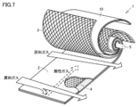
- FIG. 7 is a schematic perspective view showing a spiral-shaped gas separation membrane element developed and provided with a partially cut portion.
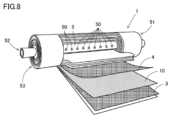
- FIG. 8 is a schematic perspective view showing the gas separation membrane element 1 with a partially developed portion.
- the spiral type gas separation membrane element 1 is A supply side flow passage member 3 through which a raw material gas containing an acid gas flows; An acid gas separation membrane sheet 10 which selectively separates and transmits acid gas contained in the source gas flowing through the supply side flow passage member 3; A permeation side flow passage member 4 through which a permeation gas containing the acid gas which has permeated the acid gas separation membrane sheet 10 flows; A sealing portion for preventing mixing of the source gas and the permeation gas; And a central pipe 5 for collecting the permeating gas flowing through the permeating side flow path member 4; A laminated body for elements in which at least one or more of the supply side flow passage member 3, the gas separation membrane 2 and the permeation side flow passage member 4 are laminated can be provided with a wound body wound around the central pipe 5 .
- the wound body may have an arbitrary shape such as a cylindrical shape or a rectangular cylindrical shape.
- the gas separation membrane element 1 may further include a fixing member (not shown) such as an outer peripheral tape or a telescope prevention plate in order to prevent unwinding and winding collapse of the wound body.
- a fixing member such as an outer peripheral tape or a telescope prevention plate in order to prevent unwinding and winding collapse of the wound body.
- an outer wrap (reinforcing layer) may be provided at the outermost periphery of the wound body.
- the supply side flow passage member 3 and the permeation side flow passage member 4 promote turbulent flow (surface renewal of the film surface) of the raw material gas and the permeated gas having permeated through the acid gas separation membrane sheet 10 to transmit the permeated gas in the raw material gas. It is preferable to have the function of increasing the membrane permeation rate of the above and the function of minimizing the pressure loss of the supplied source gas and the permeation gas that has permeated the acid gas separation membrane sheet 10 as much as possible.
- the supply side flow passage member 3 and the permeation side flow passage member 4 have a function as a spacer for forming a flow path of the source gas and the permeation gas, and a function to generate turbulent flow in the source gas and the permeation gas.
- the shape of the unit cell of the mesh is preferably selected from, for example, the shape of a square, a rectangle, a rhombus, a parallelogram, or the like according to the purpose because the gas flow path changes depending on the shape of the mesh.
- the material of the supply side flow passage member 3 and the permeation side flow passage member 4 is not particularly limited, but a material having heat resistance that can withstand the operating temperature conditions of the gas separation apparatus in which the gas separation membrane element 1 is provided is preferable.
- the sealing portion is provided to prevent mixing of the source gas and the permeation gas, and is formed, for example, by the permeation of the sealing material into the permeation side flow passage member 4 and the acid gas separation membrane sheet 10 and curing.
- the sealing portion is generally at the center among the ends located at both ends in a direction parallel to the axis of the central tube 5 of the wound body, and the ends located at both ends in the direction orthogonal to the axis of the central tube 5. It can be provided at the end of the long side of the distance between the tube 5 and the end so as to form a so-called envelope.
- the sealing part can use the material generally used as an adhesive agent, for example, an epoxy resin etc. can be used.
- the central pipe 5 is a conduit for collecting the permeated gas that has permeated the acid gas separation membrane sheet 10 and discharging the permeated gas from the gas separation membrane element 1.
- the central pipe 5 is preferably a material having heat resistance that can withstand the operating temperature conditions of the gas separation device in which the gas separation membrane element 1 is provided, and having mechanical strength that can withstand the winding of the element laminate.
- the central pipe 5 has, on its outer peripheral surface, a plurality of holes 30 communicating the flow passage space of the permeation gas formed by the permeation side flow channel member 4 and the hollow space inside the central pipe 5. doing.
- the gas separation membrane element 1 can be used for a gas separation membrane module, and the gas separation membrane module has one or more gas separation membrane elements 1.
- the gas separation membrane module comprises a source gas supply port (portion communicating with the supply side end 51 shown in FIG. 8) for supplying the source gas to the acid gas separation membrane sheet, and a permeation gas that has permeated the acid gas separation membrane sheet.
- a permeate gas outlet for discharging (part communicating with the outlet 52 shown in FIG. 8), and a non-permeate gas outlet for discharging the source gas which did not permeate the acid gas separation membrane sheet (shown in FIG. 8) (A portion communicating with the discharge end 53).
- the above raw material gas supply port, non-permeate gas discharge port and permeate gas discharge port may be provided in the main body of the gas separation membrane element, and may be referred to as a container (hereinafter referred to as "housing") for containing the gas separation membrane element ) May be provided.
- the housing can form a space for sealing the source gas flowing in the separation membrane module, and for example, a cylindrical member such as stainless steel, and a closing member for closing both axial ends of the cylindrical member. May be included.
- the housing may have any cylindrical shape such as a cylindrical shape or a rectangular cylindrical shape, but the gas separation membrane element 1 is preferably cylindrical since it is generally cylindrical. Further, inside the housing, mixing of the raw material gas supplied to the supply side end 51 and the non-permeated gas which has not permeated the acid gas separation membrane sheet 10 provided in the gas separation membrane element 1 is prevented.
- a partition can be provided.
- the raw material gases supplied to the respective gas separation membrane elements 1 may be supplied in parallel or may be supplied in series.
- supplying the raw material gas in parallel means distributing at least the raw material gas and introducing it into a plurality of gas separation membrane elements, and supplying the raw material gas in series means at least from the gas separation membrane element 1 of the former stage It refers to introducing the discharged permeating gas and / or non-permeating gas into the gas separation membrane element 1 in the latter stage.
- the average value of the second peeling strength and the ratio of the standard deviation of the second peeling strength to the average value are the peeling tester (manufactured by AIKO ENGINEERING CO., LTD .; trade name: embossed carrier tape peeling
- the time-lapse data of peel strength was measured using a tester "MODEL-2165P", and the obtained time-lapse data was obtained from the average value and standard deviation of the peel strength between 5 seconds after start of measurement and 15 seconds after measurement.
- temporal data of a specific peeling strength is as follows.
- Supply side flow passage member PPS net 1 layer (50 ⁇ 50 mesh) (manufactured by Daio Kasei Co., Ltd .; trade name: 50-150 PPS)
- Permeate side channel member Three layers of PPS net (50 ⁇ 50 mesh / 60 ⁇ 40 mesh / 50 ⁇ 50 mesh) (manufactured by Daio Kasei Co., Ltd .; trade names: 50-150 PPS and 60 (40) -150 PPS)
- Central tube A total of 20 holes of 3 mm in diameter made of stainless steel with an outer diameter of 1 inch are formed on the outer wall of the central tube.
- the holes are formed in two rows in a direction parallel to the axis of the central tube, and 25.4 mm in size so as to provide uniform spacing over a range of directions parallel to the axis of the central tube on which the laminate is wound. At the pitch, 10 holes are formed per row. Two rows are provided at opposing positions across the axis of the central tube.
- the acid gas separation membrane sheet obtained in each Example and each Comparative Example is cut into a quadrilateral shape except for a region including a liquid layer in which an abnormality is detected based on a mark applied in a marking step described later,
- the two porous layers were turned inside and folded in two, and the above-mentioned supply side flow path member was sandwiched to obtain a membrane leaf.
- One end of the first-layer permeation-side flow path member is fixed to the central pipe, and the membrane leaf (first-layer membrane leaf) obtained above is separated from the central pipe on the transmission-side flow path member and laminated. did.
- the second-layer permeation side flow path member is laminated on the first-layer membrane leaf, and both ends in the direction parallel to the axis of the central tube of the first-layer membrane leaf, and the first-layer membrane
- An epoxy-based adhesive (the end of the leaf located at both ends in the direction orthogonal to the axis of the central pipe of the leaf) on the second-layer permeation side flow path member corresponding to the end remote from the central pipe Alemco Products, Inc .; trade name: 2310) was applied.
- the second layer of membrane leaf was laminated in the same manner as described above, and the third layer of permeation side flow path member was further laminated to obtain a membrane leaf laminate.
- the membrane leaf of the second layer was laminated to be separated from the central pipe more than the permeation side flow path member of the second layer.
- the gas separation membrane is separated so that the supply side end 51 side of the gas separation membrane element 1 and the discharge port 52 side of the central pipe are separated by the acid gas separation membrane sheet 10 of the gas separation membrane element 1.
- the element 1 was fixed in a stainless steel housing 55 in a test apparatus N.
- the outlet 52 side of the central pipe was led out of the housing 55, and the other side was closed.
- the supply side end 51 and the discharge side end 53 of the gas separation membrane element 1 were opened into the housing 55. That is, the gas supplied to the housing 55 was made to flow into the interior of the gas separation membrane element 1 from the supply side end 51 and the discharge side end 53 of the gas separation membrane element 1 on the supply side.
- a cylinder for supplying nitrogen (N 2 ) gas into the housing 55 was attached via a valve, and a pressure gauge 56 for measuring the pressure in the housing 55 was attached. Then, N 2 gas at room temperature (20 ° C.) is supplied into the housing 55, and a pressure of 1500 kPaG (G indicates a gauge pressure) is applied to the supply side end 51 side of the gas separation membrane element 1. . The pressure was confirmed by a pressure gauge 56. On the other hand, the pressure on the outlet 52 side of the central pipe was adjusted to the atmospheric pressure.
- Example 1 161.38 parts by mass of water as a medium, 4 parts by mass of cross-linked polyacrylic acid (manufactured by Sumitomo Seika Chemicals Co., Ltd .; trade name: Akpek "HV-501") as a hydrophilic resin, and non-cross-linked polyacrylic acid (Sumitomo A purification solution was prepared in which 0.8 parts by mass of Akapuna “AP-40F (40% Na saponified)” and 0.8 parts by mass were added to the raw material tank 31 and the hydrophilic resin was dispersed in water. .
- the hydrophilic resin composition liquid obtained in the preparation step is transferred from the raw material tank 31 to the stirring tank 32 equipped with a rotary wing type stirrer, and the hydrophilic resin composition is contained in the stirring tank 32.
- the solution was heated to a temperature of 30 ⁇ 1 ° C. (temperature control step). Thereafter, in the stirring tank 32, the temperature was maintained at 30 ⁇ 1 ° C. and stirring was performed for 4 hours (stirring step).
- the details and stirring conditions of the stirring tank 32 are as follows.
- a hydrophobic porous PTFE membrane manufactured by Sumitomo Electric Fine Polymer Co., Ltd .; trade name: Poreflon “HP-010-50”
- the hydrophilic resin composition liquid obtained above was applied onto one surface of the layer 11 at a temperature of 20 to 25 ° C. to form a liquid layer.
- Imaging device (Nagase Sangyo Co., Ltd .; trade name: line sensor camera “XCM6040SAT2V1-F-N”, light source (manufactured by Hayashi Clock Co., Ltd .; trade name: narrow line LED illumination (white) 1200 mm long))
- the liquid layer formed in the application step was imaged using the imaging step (imaging step).
- the obtained image is binarized and analyzed using an image analysis device (manufactured by Nagase Sangyo Co., Ltd .; trade name: SCANTEC "8000”) to detect abnormalities on the surface of the liquid layer and the inside of the liquid layer.
- image analysis device manufactured by Nagase Sangyo Co., Ltd .; trade name: SCANTEC "8000
- the first porous layer 11 to which the hydrophilic resin composition liquid was applied was transported to a drying furnace 39 and dried at a temperature of about 120 ° C. for about 20 minutes to form a coating layer.
- the second porous layer 12 unwound from the second porous layer wound body 12 a is stacked in a room in which the environmental humidity is adjusted to a range of 60% RH to 65% RH, and the laminate 13 is obtained.
- the laminate 18 was formed into a roll and wound up.
- the same hydrophobic PTFE porous membrane as that used for the first porous layer 11 was used.
- the contact angle of water in the 2nd porous layer 12 was measured using an above-mentioned method, it was 125 degrees in temperature 25 ° C.
- the laminate 18 wound up in a roll was unwound and conveyed to the additional drying furnace 49 and dried at a temperature of about 120 ° C. for about 20 minutes. Subsequently, a mark is provided on the second porous layer 12 so that a region including the liquid layer in which the abnormality is detected can be recognized based on the information acquired in the abnormality detection step (marking step), and the laminate 18 is It wound up in the shape of a roll.
- a gas separation membrane element was produced using the obtained laminate 18 according to the above-mentioned production procedure, and an airtight test was conducted.
- a sample for measurement of peel strength in an acid gas separation membrane sheet is collected, and from the measurement results of peel strength in the measurement sample, the average value of the second peel strength and the standard of the second peel strength The ratio of the deviation to the mean (standard deviation / mean) was calculated. The results are shown in Table 1.
- Example 2 An acidic gas separation membrane sheet was obtained in the same manner as in Example 1 except that the environmental humidity in the laminating step was set to a range of 80% RH to 85% RH. The peel strength of the obtained acid gas separation membrane sheet was measured, and the ratio of the average value of the second peel strengths and the standard deviation of the second peel strengths to the average value (standard deviation / average value) was calculated. Moreover, the airtight test was done using the obtained acidic gas separation membrane sheet. The results are shown in Table 1.
- Example 3 An acidic gas separation membrane sheet was obtained in the same manner as in Example 1 except that the environmental humidity in the lamination step was in the range of 40% RH to 45% RH and the inspection step (the abnormality detection step and the marking step) was not performed. The The peel strength of the obtained acid gas separation membrane sheet was measured, and the ratio of the average value of the second peel strengths and the standard deviation of the second peel strengths to the average value (standard deviation / average value) was calculated. Moreover, the airtight test was done using the obtained acidic gas separation membrane sheet. The results are shown in Table 1.
- Comparative Example 1 An acid gas separation membrane sheet was obtained in the same manner as in Example 1, except that defoaming step-1, defoaming step-2, and inspection steps (abnormal detection step and marking step) were not performed.
- the peel strength of the obtained acid gas separation membrane sheet was measured, and the ratio of the average value of the second peel strengths and the standard deviation of the second peel strengths to the average value (standard deviation / average value) was calculated.
- the airtight test was done using the obtained acidic gas separation membrane sheet. The results are shown in Table 1.
- Comparative Example 2 An acidic gas separation membrane sheet was obtained in the same manner as in Example 1 except that the environmental humidity in the lamination step was in the range of 30% RH to 35% RH. The peel strength of the obtained acid gas separation membrane sheet was measured, and the ratio of the average value of the second peel strengths and the standard deviation of the second peel strengths to the average value (standard deviation / average value) was calculated. Moreover, the airtight test was done using the obtained acidic gas separation membrane sheet. The results are shown in Table 1.
- the second peel strength is the first peel because the hydrophilic resin composition layer 15 was present on the surface on the first porous layer 11 side at the time of measurement of the peel strength. It was judged that it was smaller than the strength.
Landscapes
- Chemical & Material Sciences (AREA)
- Chemical Kinetics & Catalysis (AREA)
- Engineering & Computer Science (AREA)
- Manufacturing & Machinery (AREA)
- Medicinal Chemistry (AREA)
- Polymers & Plastics (AREA)
- Organic Chemistry (AREA)
- Health & Medical Sciences (AREA)
- Dispersion Chemistry (AREA)
- Analytical Chemistry (AREA)
- General Chemical & Material Sciences (AREA)
- Oil, Petroleum & Natural Gas (AREA)
- Materials Engineering (AREA)
- Inorganic Chemistry (AREA)
- Separation Using Semi-Permeable Membranes (AREA)
- Compositions Of Macromolecular Compounds (AREA)
Priority Applications (3)
| Application Number | Priority Date | Filing Date | Title |
|---|---|---|---|
| EP18878204.9A EP3603771A4 (en) | 2017-11-15 | 2018-10-29 | ACID GAS SEPARATION MEMBRANE SHEET AND ITS MANUFACTURING PROCESS |
| US16/609,389 US11642621B2 (en) | 2017-11-15 | 2018-10-29 | Acidic gas separation membrane sheet and manufacturing method therefor |
| CN201880034595.9A CN110662593B (zh) | 2017-11-15 | 2018-10-29 | 酸性气体分离膜片及其制造方法 |
Applications Claiming Priority (2)
| Application Number | Priority Date | Filing Date | Title |
|---|---|---|---|
| JP2017-220269 | 2017-11-15 | ||
| JP2017220269A JP6648092B2 (ja) | 2017-11-15 | 2017-11-15 | 酸性ガス分離膜シート及びその製造方法 |
Publications (1)
| Publication Number | Publication Date |
|---|---|
| WO2019097994A1 true WO2019097994A1 (ja) | 2019-05-23 |
Family
ID=66539818
Family Applications (1)
| Application Number | Title | Priority Date | Filing Date |
|---|---|---|---|
| PCT/JP2018/040089 Ceased WO2019097994A1 (ja) | 2017-11-15 | 2018-10-29 | 酸性ガス分離膜シート及びその製造方法 |
Country Status (5)
| Country | Link |
|---|---|
| US (1) | US11642621B2 (enExample) |
| EP (1) | EP3603771A4 (enExample) |
| JP (1) | JP6648092B2 (enExample) |
| CN (1) | CN110662593B (enExample) |
| WO (1) | WO2019097994A1 (enExample) |
Cited By (1)
| Publication number | Priority date | Publication date | Assignee | Title |
|---|---|---|---|---|
| WO2021153062A1 (ja) * | 2020-01-31 | 2021-08-05 | 住友化学株式会社 | ガス分離膜エレメント、ガス分離膜モジュール、及びガス分離装置 |
Families Citing this family (8)
| Publication number | Priority date | Publication date | Assignee | Title |
|---|---|---|---|---|
| JP7089356B2 (ja) * | 2017-11-15 | 2022-06-22 | 住友化学株式会社 | 酸性ガス分離膜シートの製造方法及び製造装置 |
| KR102161292B1 (ko) * | 2017-11-24 | 2020-09-29 | 주식회사 엘지화학 | 불소계 수지 다공성 막 및 그 제조방법 |
| JP2021094495A (ja) * | 2019-12-13 | 2021-06-24 | 住友化学株式会社 | 分離膜シート、分離膜エレメント、分離膜モジュール、及び分離装置 |
| WO2022009514A1 (ja) * | 2020-07-06 | 2022-01-13 | 株式会社ルネッサンス・エナジー・リサーチ | ガス分離方法及び装置 |
| BR112023017762A2 (pt) * | 2021-03-05 | 2023-10-03 | Gore & Ass | Artigo compósito de polímero com sólidos retidos e métodos de formação |
| CN116963831A (zh) * | 2021-03-05 | 2023-10-27 | W.L.戈尔及同仁股份有限公司 | 具有保留固体的聚合物复合制品及其形成方法 |
| MX2023013560A (es) * | 2021-05-18 | 2023-11-29 | Gore & Ass | Articulo sorbente con capa de barrera selectiva. |
| CN117320807A (zh) * | 2021-05-18 | 2023-12-29 | W.L.戈尔及同仁股份有限公司 | 具有选择性阻挡层的吸着剂制品 |
Citations (9)
| Publication number | Priority date | Publication date | Assignee | Title |
|---|---|---|---|---|
| JPH0788171A (ja) | 1993-06-18 | 1995-04-04 | Sanyo Chem Ind Ltd | 紙おむつ用吸収剤組成物 |
| JP2879057B2 (ja) | 1995-03-10 | 1999-04-05 | 工業技術院長 | 二酸化炭素分離促進輸送膜 |
| JP2003268009A (ja) | 2002-03-18 | 2003-09-25 | Sumitomo Seika Chem Co Ltd | カルボキシル基含有水溶性重合体の製造方法 |
| JP2009195900A (ja) | 2008-01-24 | 2009-09-03 | Renaissance Energy Research:Kk | 二酸化炭素分離装置 |
| JP2014065025A (ja) * | 2012-06-20 | 2014-04-17 | Fujifilm Corp | 酸性ガス分離モジュール、及び酸性ガス分離システム |
| WO2014157069A1 (ja) * | 2013-03-29 | 2014-10-02 | 株式会社ルネッサンス・エナジー・リサーチ | Co2促進輸送膜、その製造方法及び当該製造方法に用いられる樹脂組成物、並びに、co2分離モジュール、co2分離方法及び装置 |
| JP2015027644A (ja) * | 2013-07-30 | 2015-02-12 | 富士フイルム株式会社 | 促進輸送型分離膜の製造方法および促進輸送型分離膜 |
| JP2015112502A (ja) * | 2013-12-07 | 2015-06-22 | 住友化学株式会社 | 積層体及びガス分離膜並びに積層体の製造方法 |
| WO2016024523A1 (ja) | 2014-08-11 | 2016-02-18 | 住友化学株式会社 | Co2ガス分離膜用組成物、co2ガス分離膜及びその製造方法並びにco2ガス分離膜モジュール |
Family Cites Families (11)
| Publication number | Priority date | Publication date | Assignee | Title |
|---|---|---|---|---|
| US7940382B2 (en) | 2007-03-16 | 2011-05-10 | Asahi Kasei Chemicals Corporation | Method for inspecting defect of hollow fiber porous membrane, defect inspection equipment and production method |
| CN102068924B (zh) * | 2010-12-22 | 2013-12-18 | 中国科学院长春应用化学研究所 | 一种聚四氟乙烯复合膜及其制备方法 |
| JP5865317B2 (ja) * | 2012-09-28 | 2016-02-17 | 富士フイルム株式会社 | 二酸化炭素分離用複合体、二酸化炭素分離用モジュール、及び二酸化炭素分離用複合体の製造方法 |
| US20140231340A1 (en) * | 2013-02-15 | 2014-08-21 | Pall Corporation | Composite including ptfe membrane |
| JP6161124B2 (ja) * | 2013-03-29 | 2017-07-12 | 富士フイルム株式会社 | 酸性ガス分離複合膜の製造方法及び酸性ガス分離膜モジュール |
| JP6097151B2 (ja) * | 2013-05-27 | 2017-03-15 | 住友化学株式会社 | ガス分離膜の製造方法 |
| JP5990555B2 (ja) | 2013-07-17 | 2016-09-14 | 富士フイルム株式会社 | 酸性ガス分離膜の製造方法および酸性ガス分離膜巻回物 |
| GB201317521D0 (en) * | 2013-10-03 | 2013-11-20 | Fujifilm Mfg Europe Bv | Membranes |
| JP6257301B2 (ja) * | 2013-12-16 | 2018-01-10 | 株式会社Roki | イオン交換器 |
| CN106839269B (zh) | 2016-12-26 | 2019-08-27 | 奥克斯空调股份有限公司 | 一种空调舒适性控制方法 |
| JP7089356B2 (ja) | 2017-11-15 | 2022-06-22 | 住友化学株式会社 | 酸性ガス分離膜シートの製造方法及び製造装置 |
-
2017
- 2017-11-15 JP JP2017220269A patent/JP6648092B2/ja active Active
-
2018
- 2018-10-29 EP EP18878204.9A patent/EP3603771A4/en not_active Withdrawn
- 2018-10-29 WO PCT/JP2018/040089 patent/WO2019097994A1/ja not_active Ceased
- 2018-10-29 US US16/609,389 patent/US11642621B2/en active Active
- 2018-10-29 CN CN201880034595.9A patent/CN110662593B/zh active Active
Patent Citations (9)
| Publication number | Priority date | Publication date | Assignee | Title |
|---|---|---|---|---|
| JPH0788171A (ja) | 1993-06-18 | 1995-04-04 | Sanyo Chem Ind Ltd | 紙おむつ用吸収剤組成物 |
| JP2879057B2 (ja) | 1995-03-10 | 1999-04-05 | 工業技術院長 | 二酸化炭素分離促進輸送膜 |
| JP2003268009A (ja) | 2002-03-18 | 2003-09-25 | Sumitomo Seika Chem Co Ltd | カルボキシル基含有水溶性重合体の製造方法 |
| JP2009195900A (ja) | 2008-01-24 | 2009-09-03 | Renaissance Energy Research:Kk | 二酸化炭素分離装置 |
| JP2014065025A (ja) * | 2012-06-20 | 2014-04-17 | Fujifilm Corp | 酸性ガス分離モジュール、及び酸性ガス分離システム |
| WO2014157069A1 (ja) * | 2013-03-29 | 2014-10-02 | 株式会社ルネッサンス・エナジー・リサーチ | Co2促進輸送膜、その製造方法及び当該製造方法に用いられる樹脂組成物、並びに、co2分離モジュール、co2分離方法及び装置 |
| JP2015027644A (ja) * | 2013-07-30 | 2015-02-12 | 富士フイルム株式会社 | 促進輸送型分離膜の製造方法および促進輸送型分離膜 |
| JP2015112502A (ja) * | 2013-12-07 | 2015-06-22 | 住友化学株式会社 | 積層体及びガス分離膜並びに積層体の製造方法 |
| WO2016024523A1 (ja) | 2014-08-11 | 2016-02-18 | 住友化学株式会社 | Co2ガス分離膜用組成物、co2ガス分離膜及びその製造方法並びにco2ガス分離膜モジュール |
Cited By (3)
| Publication number | Priority date | Publication date | Assignee | Title |
|---|---|---|---|---|
| WO2021153062A1 (ja) * | 2020-01-31 | 2021-08-05 | 住友化学株式会社 | ガス分離膜エレメント、ガス分離膜モジュール、及びガス分離装置 |
| JP2021121416A (ja) * | 2020-01-31 | 2021-08-26 | 住友化学株式会社 | ガス分離膜エレメント、ガス分離膜モジュール、及びガス分離装置 |
| JP7397697B2 (ja) | 2020-01-31 | 2023-12-13 | 住友化学株式会社 | ガス分離膜エレメント、ガス分離膜モジュール、及びガス分離装置 |
Also Published As
| Publication number | Publication date |
|---|---|
| JP6648092B2 (ja) | 2020-02-14 |
| CN110662593B (zh) | 2022-01-11 |
| EP3603771A1 (en) | 2020-02-05 |
| CN110662593A (zh) | 2020-01-07 |
| US20200061530A1 (en) | 2020-02-27 |
| US11642621B2 (en) | 2023-05-09 |
| JP2019089033A (ja) | 2019-06-13 |
| EP3603771A4 (en) | 2020-10-28 |
Similar Documents
| Publication | Publication Date | Title |
|---|---|---|
| CN110662593B (zh) | 酸性气体分离膜片及其制造方法 | |
| EP3711845B1 (en) | Method and apparatus for producing acidic gas separation membrane sheet | |
| TWI698274B (zh) | 螺旋形酸性氣體分離膜元件、酸性氣體分離膜模組,以及酸性氣體分離裝置 | |
| TWI716574B (zh) | 酸性氣體分離膜及使用該分離膜之酸性氣體分離方法,以及酸性氣體分離模組及酸性氣體分離裝置 | |
| JP6602502B2 (ja) | ガス分離膜エレメント、ガス分離膜モジュール、及びガス分離装置 | |
| CN111132752B (zh) | 分离膜片、分离膜元件、分离膜模块和分离膜片的制造方法 | |
| CN110545896A (zh) | 螺旋型气体分离膜元件、气体分离膜模块及气体分离装置 | |
| WO2019009000A1 (ja) | ガス分離膜エレメント、ガス分離膜モジュール、及びガス分離装置 | |
| JP7397697B2 (ja) | ガス分離膜エレメント、ガス分離膜モジュール、及びガス分離装置 | |
| WO2021117362A1 (ja) | ガス分離方法及びガス分離装置 | |
| WO2021117361A1 (ja) | 分離膜シート、分離膜エレメント、分離膜モジュール、及び分離装置 |
Legal Events
| Date | Code | Title | Description |
|---|---|---|---|
| 121 | Ep: the epo has been informed by wipo that ep was designated in this application |
Ref document number: 18878204 Country of ref document: EP Kind code of ref document: A1 |
|
| ENP | Entry into the national phase |
Ref document number: 2018878204 Country of ref document: EP Effective date: 20191031 |
|
| NENP | Non-entry into the national phase |
Ref country code: DE |