WO2019082585A1 - ガラス板の折割機械 - Google Patents
ガラス板の折割機械Info
- Publication number
- WO2019082585A1 WO2019082585A1 PCT/JP2018/035819 JP2018035819W WO2019082585A1 WO 2019082585 A1 WO2019082585 A1 WO 2019082585A1 JP 2018035819 W JP2018035819 W JP 2018035819W WO 2019082585 A1 WO2019082585 A1 WO 2019082585A1
- Authority
- WO
- WIPO (PCT)
- Prior art keywords
- glass plate
- pushing
- moving
- glass
- pressing
- Prior art date
Links
Images


Classifications
-
- B—PERFORMING OPERATIONS; TRANSPORTING
- B65—CONVEYING; PACKING; STORING; HANDLING THIN OR FILAMENTARY MATERIAL
- B65G—TRANSPORT OR STORAGE DEVICES, e.g. CONVEYORS FOR LOADING OR TIPPING, SHOP CONVEYOR SYSTEMS OR PNEUMATIC TUBE CONVEYORS
- B65G49/00—Conveying systems characterised by their application for specified purposes not otherwise provided for
- B65G49/05—Conveying systems characterised by their application for specified purposes not otherwise provided for for fragile or damageable materials or articles
- B65G49/06—Conveying systems characterised by their application for specified purposes not otherwise provided for for fragile or damageable materials or articles for fragile sheets, e.g. glass
- B65G49/063—Transporting devices for sheet glass
- B65G49/064—Transporting devices for sheet glass in a horizontal position
-
- C—CHEMISTRY; METALLURGY
- C03—GLASS; MINERAL OR SLAG WOOL
- C03B—MANUFACTURE, SHAPING, OR SUPPLEMENTARY PROCESSES
- C03B33/00—Severing cooled glass
- C03B33/02—Cutting or splitting sheet glass or ribbons; Apparatus or machines therefor
- C03B33/023—Cutting or splitting sheet glass or ribbons; Apparatus or machines therefor the sheet or ribbon being in a horizontal position
- C03B33/03—Glass cutting tables; Apparatus for transporting or handling sheet glass during the cutting or breaking operations
-
- B—PERFORMING OPERATIONS; TRANSPORTING
- B26—HAND CUTTING TOOLS; CUTTING; SEVERING
- B26F—PERFORATING; PUNCHING; CUTTING-OUT; STAMPING-OUT; SEVERING BY MEANS OTHER THAN CUTTING
- B26F3/00—Severing by means other than cutting; Apparatus therefor
-
- B—PERFORMING OPERATIONS; TRANSPORTING
- B26—HAND CUTTING TOOLS; CUTTING; SEVERING
- B26F—PERFORATING; PUNCHING; CUTTING-OUT; STAMPING-OUT; SEVERING BY MEANS OTHER THAN CUTTING
- B26F3/00—Severing by means other than cutting; Apparatus therefor
- B26F3/002—Precutting and tensioning or breaking
-
- B—PERFORMING OPERATIONS; TRANSPORTING
- B28—WORKING CEMENT, CLAY, OR STONE
- B28D—WORKING STONE OR STONE-LIKE MATERIALS
- B28D5/00—Fine working of gems, jewels, crystals, e.g. of semiconductor material; apparatus or devices therefor
-
- B—PERFORMING OPERATIONS; TRANSPORTING
- B28—WORKING CEMENT, CLAY, OR STONE
- B28D—WORKING STONE OR STONE-LIKE MATERIALS
- B28D7/00—Accessories specially adapted for use with machines or devices of the preceding groups
- B28D7/04—Accessories specially adapted for use with machines or devices of the preceding groups for supporting or holding work or conveying or discharging work
-
- C—CHEMISTRY; METALLURGY
- C03—GLASS; MINERAL OR SLAG WOOL
- C03B—MANUFACTURE, SHAPING, OR SUPPLEMENTARY PROCESSES
- C03B33/00—Severing cooled glass
- C03B33/02—Cutting or splitting sheet glass or ribbons; Apparatus or machines therefor
- C03B33/023—Cutting or splitting sheet glass or ribbons; Apparatus or machines therefor the sheet or ribbon being in a horizontal position
- C03B33/033—Apparatus for opening score lines in glass sheets
-
- C—CHEMISTRY; METALLURGY
- C03—GLASS; MINERAL OR SLAG WOOL
- C03B—MANUFACTURE, SHAPING, OR SUPPLEMENTARY PROCESSES
- C03B33/00—Severing cooled glass
- C03B33/02—Cutting or splitting sheet glass or ribbons; Apparatus or machines therefor
- C03B33/04—Cutting or splitting in curves, especially for making spectacle lenses
-
- B—PERFORMING OPERATIONS; TRANSPORTING
- B65—CONVEYING; PACKING; STORING; HANDLING THIN OR FILAMENTARY MATERIAL
- B65G—TRANSPORT OR STORAGE DEVICES, e.g. CONVEYORS FOR LOADING OR TIPPING, SHOP CONVEYOR SYSTEMS OR PNEUMATIC TUBE CONVEYORS
- B65G2249/00—Aspects relating to conveying systems for the manufacture of fragile sheets
- B65G2249/04—Arrangements of vacuum systems or suction cups
Definitions
- the present invention relates to a glass sheet breaking machine.
- the cleaving device is moved along a split line formed on the glass plate in a plane parallel to the surface of the glass plate placed on the endless belt, while the glass plate receiving device is broken down below the endless belt.
- Glass sheet breaking machines are known which are adapted to be moved in correspondence with the movement of the device.
- the glass sheet receiving surface of the glass sheet receiving device is disposed on the lower surface of the glass sheet in a region surrounded by the dividing line when pressing against the glass sheet along the cutting line
- the pressing rod is pressed outside the area surrounded by the dividing line against the upper surface of the glass sheet whose lower surface is supported by the glass sheet receiving surface disposed in such an area, and the glass sheet is pushed and split along the dividing line
- the glass plate receiving surface may push up the breaking cullet after the pressing, and the lifting of the breaking cullet may occur.
- the glass plate as a product may be chipped or the like on the cracked surface.
- the present invention has been made in view of the above-mentioned points, and an object of the present invention is to provide a glass sheet breaking machine which does not cause chipping or the like in a broken surface of a glass sheet as a product after being crushed. It is in.
- a glass plate receiving apparatus having a mechanism, an annular glass plate receiving surface for receiving a glass plate from the lower surface of the glass plate via a flexible member, and a recess surrounded by the annular glass plate receiving surface;
- a first moving device for moving the glass plate receiving surface of the glass plate receiving device, a pushing and dividing device for pushing the glass plate from the upper surface of the glass plate and pushing and breaking it along the score line, and
- the second moving device has a glass facing the recess surrounded by the glass plate receiving surface moved by the first moving device when the second moving device is pushed and split by the pushing device against the glass plate.
- Push the board In order to be able to release the squeeze device, the squeeze device presses the glass plate facing the recess surrounded by the glass plate receiving surface and squeezes the glass plate along the cutting line It is supposed to be
- the glass sheet receiving device has an annular glass sheet receiving surface and a recess surrounded by the annular glass sheet receiving surface, and One moving device is adapted to move the glass plate receiving surface, and the second moving device for moving the pressing device is the glass moved by the first moving device upon pressing and breaking by the pressing device against the glass plate.
- the pushing device so that the glass plate facing the recess surrounded by the plate receiving surface can be pressed, as a result, the region is outside the region and in contact with the region or outside the region Even if the glass plate receiving surface is arranged away from the space, or even if a part of the glass plate receiving surface is arranged in the area and the remaining portion is arranged outside the area, it is caused by the bending of the glass plate in the recess. Cut in the glass plate Can be avoided, so that collisions between the split cullet and the split surface of the glass sheet as a product after the split can be avoided, and chips or the like occur on the split surface of the glass sheet as the product after the split. It can eliminate the occurrence.
- the glass sheet breaking machine includes a flexible member on which a glass sheet having a cutting line formed thereon is placed, and the glass sheet through the flexible member.
- a support mechanism having a support surface supported at a central portion of the lower surface in a region surrounded by a cutting line of the glass substrate in a plan view of the glass plate, and an annular member receiving the glass plate from the lower surface of the glass plate via a flexible member
- a glass plate receiving device having a glass plate receiving surface and a recess surrounded by the annular glass plate receiving surface and disposed below the flexible member, and a glass plate receiving surface of the glass plate receiving device
- a second moving device for moving the pushing surface of the device The first moving device is a glass so that the pressing surface of the pressing device can press the glass plate facing the recess surrounded by the receiving surface of the glass when pressing the pressing surface
- the plate receiving surface is arranged, and the second moving device faces the recess surrounded by the glass plate receiving surface moved by the first moving device when the pressing surface of the glass plate is pressed and split.
- the pressing surface is arranged so that the pressing glass surface can be pressed by the pressing surface, and the pressing device presses the pressing surface against the glass plate facing the recess surrounded by the glass plate receiving surface, It is designed to cut the glass plate along the cutting line.
- the glass sheet receiving device has an annular glass sheet receiving surface and a recess surrounded by the annular glass sheet receiving surface.
- the first moving device is a glass plate so that the pressing surface of the splitting device can press the glass plate facing the recess surrounded by the glass plate receiving surface when the pressing surface against the glass plate is split.
- the receiving surface is moved, and the second moving device is disposed in the recess surrounded by the glass plate receiving surface moved by the first moving device when the pressing force against the glass plate is split.
- the glass plate receiving surface is disposed outside the region and in contact with the region or outside the region away from the region Also, even if a part of the glass sheet receiving surface is placed in the area and the remaining part is placed outside the area, the glass sheet breaks at the score line due to the bending of the glass sheet in the recess. It is possible to prevent the collision between the cullet and the cracked surface of the glass plate as a product after crushing, and the chipping surface of the glass plate as a product after crushing is generated. You can get rid of
- the annular glass plate receiving surface is coplanar with the support surface of the support mechanism, relative to the support surface of the support mechanism, in the pushing along the cutting line of the glass plate by the pushing surface of the pushing device.
- the glass plate receiving surface is annular, and the recess is a partially concave spherical surface It is prescribed.
- the first moving device moves the glass plate receiving surface in one direction and the other direction intersecting the one direction in a plane parallel to the plane of the glass plate.
- the second moving device is configured to move the pushing surface in one direction and the other direction intersecting the one direction in a plane parallel to the plane of the glass plate.
- the flexible member comprises an endless belt
- the glass sheet breaking machine comprises a means for applying tension to the endless belt and a running means for running the endless belt. ing.
- the glass plate receiving surface has, in a preferred example, a flat surface which receives the lower surface of the glass plate through the flexible member in relation to the cutter wheel in the formation of a cutting line including an end cutting line
- a flat surface may be annular, preferably toroidal, and such flat surface may be circular in its inner shape and circular in its outer shape.
- the pressing surface has, in a preferred example, a flat surface capable of pressing the upper surface of the glass plate, and the flat surface of the pressing surface is preferably sufficiently larger than the opening surface of the recess.
- the flat surface of the pushing surface is circular in outline, the glass plate receiving surface is annular, and the opening surface of the recess defined by the glass plate receiving surface is circular,
- the flat surface of the pushing surface has an inner diameter of the glass plate receiving surface, in other words, a diameter sufficiently smaller than the diameter of the opening surface of the recess, and further, the pushing surface is a partial cylinder in another preferred example.
- the pushing surface may be a conical surface or a frusto-conical surface consisting of the outer peripheral surface of a conical body or a frusto-conical body, and in addition, instead of a flat circular plane, one end of a prismatic body It may be a flat rectangular flat surface consisting of an outer peripheral surface, and if the recess is defined by a partially concave spherical surface, such a partially cylindrical surface or cylindrical surface or partially spherical surface or spherical surface of such a pushing surface is preferred.
- Glass plates to be broken by the breaking machine of the present invention include general window glass plates for buildings, glass plates for furniture, glass plates for automobiles such as front glass, rear glass or side glass, computers, mobile phones, etc. Although the glass plate for display screens of can be illustrated, it may also include other glass plates.
- a flexible endless belt which is a flexible endless member can be mentioned as a preferable example, but in addition, it may be a flexible endless sheet.
- the present invention it is possible to provide a glass sheet cracking machine which does not cause chipping or the like on the fracture surface of the glass sheet as a product after being crushed.
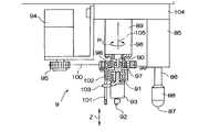
- FIG. 1 is a side view of a preferred embodiment of the present invention.
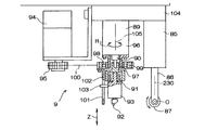
- FIG. 2 is a front view of the specific example shown in FIG.
- FIG. 3 is a plan view of the endless belt, the support member and the like in the embodiment shown in FIG.
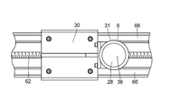
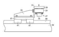
- FIG. 4 is a detailed side view of the glass plate receiving apparatus in the specific example shown in FIG.
- FIG. 5 is a detailed plan view of the glass plate receiving apparatus in the specific example shown in FIG.
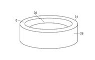
- FIG. 6 is a perspective view of a glass plate receiving member in the embodiment shown in FIG.
- FIG. 7 is a detailed side view of the press and split device in the specific example shown in FIG.
- FIG. 8 is an operation explanatory diagram of the specific example shown in FIG. FIG.
- FIG. 9 is an operation explanatory view of the glass plate receiving apparatus in the specific example shown in FIG.
- FIG. 10 is an operation explanatory diagram of the specific example shown in FIG.
- FIG. 11 is an operation explanatory diagram of the specific example shown in FIG.
- FIG. 12 is a cross-sectional explanatory view of a modification of the glass plate receiving member in the specific example shown in FIG.
- FIG. 13 is an explanatory view of a modification of the pressing surface in the specific example shown in FIG.
- FIG. 14 is an explanatory view of another modification of the pressing surface in the specific example shown in FIG.
- FIG. 15 is an explanatory view of a modification of the pushing and dividing apparatus in the specific example shown in FIG.
- the glass sheet breaking machine 1 of this example includes the flexible endless belt 3 as a flexible member on which the glass sheet 2 is placed, and the periphery of the upper portion of the endless belt 3 And an annular glass which receives the glass plate 2 from the lower surface of the glass plate 2 via the endless belt 3 in the region 5 surrounded by the support member 4 and the supporting member 4 supporting the lower surface side thereof.
- each of the glass plate receiving devices 7 and 7a is arranged in a plane parallel to the plane of the glass plate 2;
- Moving device 8 for moving in the direction, Y direction orthogonal to the X direction in this example, and 8a and a plurality of, in this example, two, split devices 9 and 9a disposed above the upper portion of the endless belt 3, and each of the split devices 9 and 9a are in one direction in the horizontal plane
- Moving devices 10 and 10a for moving in the X direction and another direction intersecting the X direction, in this example, the Y direction orthogonal to the X direction, and a region 5 in which the glass plate 2 before breaking is surrounded by the support member 4
- a frame 13 having a traveling device 13 for traveling in the A direction in the X direction, a support mechanism 15 having an upper surface 51 as a support surface for supporting the glass plate
- the glass plate receivers 7 and 7a respectively, the moving devices 8 and 8a respectively, the pushing devices 9 and 9a respectively and the moving devices 10 and 10a respectively are identically configured, so in the following if particularly necessary Except for the glass plate receiving device 7, the moving device 8, the pushing device 9, and the moving device 10, and the corresponding components are only illustrated with the same numeral a.
- the endless belt 3 is wound around the drive drum 17 and the driven drum 18 and the free rotating drums 19 and 20.
- the support member 4 made of a hollow rectangular member is supported by the base 23 of the frame 16 via the bracket 21 and the intermediate base 22 of the frame 16.
- the supporting member 4 may be a plate-like member instead of the hollow rectangular member, and in short, the upper side portion of the endless belt 3 is supported from the lower surface side, and the upper side portion of the endless belt 3 is extremely drooping down.
- the support member 4 may be omitted as long as the endless belt 3 can be tensioned as desired so that the upper portion of the endless belt 3 does not excessively drop.
- the drive drum 17 and the driven drum 18 function as a part of the support member 4 so that the drive drum 17 and the driven drum in the support member 4 are driven.
- the portion extending parallel to the drum 18 may be omitted.
- the glass plate receiving device 7 brings the glass plate receiving surface 6 into contact with the lower surface of the upper portion of the endless belt 3 in forming the breaking lines 221 and the end cutting lines (auxiliary cutting lines) 222, in other words, a glass plate While the receiving surface 6 is flush with the upper surface 51, the pressing of the glass plate 2 along the planned breaking line 221 and the end cutting line 222 by the pressing device 9 may be carried out as needed depending on the case.
- the cylinder unit 35 has a cylinder unit 35 attached thereto, and the cylinder unit 35 may be an air cylinder, but may be a hydraulic cylinder, and its operation raises and lowers the glass plate receiving member 28 through the piston rod. It is supposed to be.
- the flat glass plate receiving surface 6 having a circular outer contour 31 and extending parallel to the lower surface of the glass plate 2 is not moved up or down by the raising and lowering means 27, the upper surface 51 as a support surface of the support mechanism 15. And the upper surface 52 as the support surface of the support member 4 and arranged at the same height with respect to the upper surface 51 and the upper surface 52, while the glass plate receiving surface 6 is elevated by the elevation means 27.
- the upper surface 51 and the upper surface 52 are arranged to be higher by about 1 mm to 5 mm, and as shown in FIG. It is distributed as low as 1 mm to 5 mm.
- the moving device 8 includes an X-direction moving mechanism 55 and a Y-direction moving mechanism 56.
- the X-direction moving mechanism 55 includes an X-direction linear moving table 57 to which the base 30 of the glass plate receiving device 7 is attached, an electric motor 59 attached to the lateral member 58, and bearings 60 and 61 on the lateral member 58.
- the Y-direction moving mechanism 56 is configured in substantially the same manner as the X-direction moving mechanism 55, and includes a horizontal member 58 as a linear moving table in the Y direction, a support member 70, a bracket 21 and the like on the intermediate base 22.
- the pushing device 9 is attached to the air cylinder device 85 and the piston rod 86 of the air cylinder device 85 and has a circular flat pushing surface 87 smaller in diameter than the diameter of the circular recess 36 on its lower surface.
- a rod 88, an air cylinder device 89, and a piston rod 90 of the air cylinder device 89 are attached via a bearing mechanism 91, and a cutter block 93 having a cutter wheel 92 at its tip, an electric motor 94, and an electric motor
- a pulley or gear 95 attached to the output rotary shaft 94, a bearing mechanism 98 attached to the outer cylinder 96 of the air cylinder device 89 via a bracket 97, and a pulley or gear 99 attached to the bearing mechanism 98; Timing belt or chain 100 stretched between gear 95 and gear 99
- the push rod 88 is moved vertically, that is, in the Z direction, and when the piston rod 90 is expanded and contracted by the operation of the air cylinder device 89.
- the cutter wheel 92 is moved in the Z direction, and when the gear 99 is rotated via the chain 100 by the rotation of the gear 95 by the operation of the electric motor 94, the engagement member 102 and the engagement member 102 are engaged with the slit 101.
- the engaging piece 103 is also rotated in the R direction about the axial center 105, and the cutter wheel 92 is similarly rotated in the R direction about the axial center 105 by this rotation, and the cutting edge is directed in the cutting line forming direction.
- the moving device 10 includes an X-direction moving mechanism 110 and a Y-direction moving mechanism 111.
- the X-direction moving mechanism 110 includes an X-direction linear moving table 112 to which a base 104 of the pushing device 9 is attached, an electric motor 114 attached to the lateral member 113, and bearings 115 and 116 on the lateral member 113.
- a screw shaft 117 rotatably supported, and a pulley 118 fixed to an output rotation shaft of the electric motor 114 and one end of the screw shaft 117 so as to transmit rotation of the output rotation shaft of the electric motor 114 to the screw shaft 117 119 and a belt 120 stretched between the pulleys 118 and 119, a nut (not shown) attached to and fixed to the lower surface of the linear moving table 112 by screwing on a screw shaft 117, and a cross member 113.
- a pair of rails 121 formed, and a slider 1 slidably fitted on the pair of rails 121 and attached to and fixed to the lower surface of the linear moving table 112 It is androgynous and 2.
- the linear movement table 112 is guided by the pair of rails 121 and is linear in the X direction. It is supposed to be moved.
- the Y-direction moving mechanism 111 is configured in substantially the same manner as the X-direction moving mechanism 110, and fixed to the horizontal member 113 as a linear moving table in the Y direction and the upper frame 132 of the frame 16 via a bracket 133 or the like.
- the cross member 113 is suspended and supported movably in the Y direction via the slider.
- the carrying in / out means 11 lifts the glass plate 2 placed on the belt 3 and completed the cleavage, and supporting the glass plate 2 placed on the belt 3 during the cleavage via the belt 3 And the lifting mechanism 152 for placing the glass plate to be split on the belt 3 and the pair of lifting devices 151 and 152 in the Y direction. And a reciprocating mechanism 153.
- the lifting mechanism 151 includes an air cylinder device 156 attached to the movable base 155 and a vacuum suction device 158 attached to the tip of the piston rod 157 of the air cylinder device 156.
- the vacuum suction device 158 lifts the glass plate 2 placed on the belt 3 and the glass plate 2 placed on the belt 3 through the belt 3 In cooperation with the support mechanism 15, it clamps it and fixes it on the belt 3.
- the lifting mechanism 152 is formed in the same manner as the lifting mechanism 151, and includes an air cylinder device 161 attached to the movable base 155 common to the lifting mechanism 151 and a vacuum attached to the tip of the piston rod 162 of the air cylinder device 161.
- the vacuum suction device 163 places the suctioned glass plate 2 on the belt 3 when the piston rod 162 is lowered in the Z direction by the operation of the air cylinder device 161. Do.
- the reciprocating mechanism 153 includes a movable base 155, an electric motor 166 attached to the upper frame 165 of the frame 16, a screw shaft 168 rotatably supported on the upper frame 132 of the frame 16 via a bearing 167, and an electric motor
- the output rotary shaft of the electric motor 166 and pulleys 169 and 170 fixed to one end of the screw shaft 168 and the pulleys 169 and 170 are stretched so as to transmit the rotation of the output rotary shaft of the motor 166 to the screw shaft 168
- the belt 171 and a nut 172 screwed on the screw shaft 168 and attached and fixed to the upper surface of the movable table 155, a pair of rails 173 formed on the upper frame 132, and a pair of rails 173 are slidable.
- a slider 174 attached and fixed to the upper surface of the movable base 155.
- the movable base 155 supported by the upper frame 132 so as to be movable in the Y direction via the slider 174 is screwed via the pulleys 169 and 170 and the belt 171 by the rotation of its output rotary shaft by the operation of the electric motor 166.
- the shaft 168 When the shaft 168 is rotated, it is guided by the pair of rails 173 so as to be linearly reciprocated in the Y direction.
- the loading and unloading means 11 linearly reciprocates the lifting devices 151 and 152 in the Y direction by the operation of the reciprocating mechanism 153, and in this rectilinear reciprocation, the lifting device 152 is placed on the entrance side transport device 181
- the unbroken glass sheet 2 is lifted and carried into the area 5 surrounded by the support member 4 and placed on the upper surface of the upper side portion of the endless belt 3.
- the broken glass plate 2 placed on the upper surface of the upper part of the above is carried out of the area 5 surrounded by the support member 4 and placed on the delivery device 182 on the delivery side.
- the tension applying means 12 includes a pair of air cylinder devices 185 and 186 supported by the bracket 21.
- the piston rod of the air cylinder device 185 rotatably supports the free rotating drum 19, and the air cylinder
- the piston rod of the device 186 rotatably supports the free rotating drum 20.
- the tension applying means 12 applies tension to the endless belt 3 through the free rotating drums 19 and 20 by the air elastic force of the air cylinder devices 185 and 186, whereby the endless belt 3 is tensioned. There is. If the endless belt 3 can be tensioned as desired by adjusting the positions of the drive drum 17, the driven drum 18, and the free rotating drums 19 and 20, the tension applying means 12 may not be provided.
- the traveling device 13 includes an electric motor 191 mounted on a base 23, a driving drum 17, a driven drum 18, free rotating drums 19 and 20, and rotation of an output rotating shaft of the electric motor 191 as a rotating shaft of the driving drum 17.
- the drive drum 17 has pulleys 192 and 193 attached to the output rotary shaft of the electric motor 191 and the rotary shaft of the drive drum 17 and a belt 194 wound around the pulleys 192 and 193.
- the driven drum 18 is rotatably mounted on frames 195 and 196 supported by the intermediate base 22, respectively.
- the traveling device 13 rotates the drive drum 17 via the pulley 192, the belt 194 and the pulley 193 when the electric motor 191 is operated and the output rotation shaft is rotated, and the rotation of the drive drum 17 causes the belt 3 to
- the belt 3 travels in the A direction, whereby the belt 3 transports and discharges the cullet folded on the belt 3 in the A direction.
- the support mechanism 15 includes a rectangular receiving plate 201 and a support 202 for supporting the receiving plate 201, and the support 202 is supported by the bracket 21 via the cross member 203.
- the support mechanism 15 supports the glass plate 2 mounted on the endless belt 3 from below via the endless belt 3 on the upper surface 51 of the receiving plate 201 and cooperates with the vacuum suction device 158 to operate the glass plate 2. And clamp it on the belt 3.
- the entrance side conveyance device 181 includes an endless belt 211 on which the glass plate 2 to be broken is placed, and a traveling device (not shown) for causing the endless belt 211 to travel.
- the plate 2 is accurately carried in to a predetermined position by the travel of the endless belt 211 based on the operation of the travel device.
- the delivery side transport device 182 includes an endless belt 212 on which the broken glass plate 2 is placed and a traveling device (not shown) for causing the endless belt 212 to travel, and the broken glass
- the plate 2 is conveyed to the next processing step, for example, grinding and polishing of the split edge, by traveling the endless belt 212 based on the operation of the traveling device.
- the glass plate cracking machine 1 additionally has a control device comprising a microcomputer and the like, and the control device is a numerical control command in which the operation of the electric motor, the air cylinder device, the vacuum suction device and the like is preprogrammed. Control through. Since such a control device itself is known, the detailed description thereof is omitted.
- the glass sheet breaking machine 1 performs a folding operation on the glass sheet 2 as follows.
- the glass plate 2 to which a planned breaking line (main cutting line) 221 is given in advance as a cutting line is arranged by the endless belt 211 at an accurate position on the endless belt 3.
- a planned breaking line 221 may be formed by the glass plate breaking machine 1 of this embodiment.
- the vacuum suction devices 158 and 163 are operated by the operation of the air cylinder devices 156 and 161, respectively, and the broken glass on the endless belt 3 is operated by the vacuum suction device 158.
- the vacuum suction device 163 sucks the glass plate 2 to be broken next on the endless belt 211 by the vacuum suction device 163, and then the air cylinder devices 156 and 161 are operated to cause the vacuum suction device 158 to move the endless belt 3 above.
- the broken glass plate 2 is lifted by the vacuum suction device 163 to lift the glass plate 2 to be broken on the endless belt 211.
- the electric motor 166 of the reciprocating mechanism 153 is operated to move the movable table 155 forward, and the already broken glass plate 2 lifted by the vacuum suction device 158 is outside the area 5 surrounded by the support member 4.
- the glass sheet 2 to be broken up from now is taken out from the endless belt 212 and carried into the area 5 surrounded by the support member 4 on the endless belt 3.
- the electric motor 191 is operated in a state where the glass plate 2 is lifted, whereby the endless belt 3 travels in the A direction and remains on the upper side portion of the endless belt 3
- the broken cullet is conveyed in the direction A as the endless belt 3 travels and discharged.
- the operation of the electric motor 191 is stopped, and the traveling of the endless belt 3 in the A direction is stopped.
- the air cylinder devices 156 and 161 are reactivated, the vacuum suction devices 158 and 163 are lowered, and after the vacuum suction devices 158 and 163 are lowered to predetermined positions, suction of the vacuum suction devices 158 and 163 is performed. The operation is stopped, and the glass plate 2 to be broken up on the endless belt 212 by the vacuum suction device 158 is placed on the endless belt 3 by the vacuum suction device 163 and the glass plate 2 to be broken from this is placed.
- the air cylinder devices 156 and 161 are reversely operated to raise the vacuum suction devices 158 and 163, and further the electric motor 166 of the reciprocating mechanism 153 is reversely operated to move the movable base 155 back to move the vacuum suction disks.
- the device 163 is moved on the endless belt 211 and the vacuum suction device 158 is moved on the endless belt 3.
- the air cylinder devices 156 and 161 are reactivated to lower the vacuum suction devices 158 and 163 to the predetermined positions of the vacuum suction devices 158 and 163.
- the glass plate 2 placed on the upper side of the endless belt 3 is pressed against the endless belt 3 by the vacuum suction device 158 with the air elastic force based on the air cylinder device 156 and the air cylinder device 161 similarly.
- the glass plate 2 placed on the endless belt 211 by the vacuum suction device 163 is pressed against the endless belt 211 with an air elastic force based on that.
- the glass plate 2 placed on the upper side of the endless belt 3 is held between the vacuum suction device 158 and the receiving plate 201 with the endless belt 3 in the center, and the endless belt 3 is firmly fixed. It will be held and fixed on the upper side.
- the electric motors 59 and 59a and 72 and 72a are operated to move the glass plate receiving devices 7 and 7a in the X and Y directions so that the glass receiving surfaces 6 and 6a are disposed under the cutter wheels 92 and 92a.
- Operating the electric motors 114 and 114a and 135 and 135a to move the pressers 9 and 9a in the X and Y directions to move the cutter wheels 92 and 92a in the radial direction starting from the intended breaking line 221 Let At the same time as the cutter wheels 92 and 92a move from the intended fracture line 221, the air cylinder devices 89 and 89a are simultaneously operated to bring the cutter wheels 92 and 92a into contact with the glass plate 2, whereby the cutter wheels 92 and 92a An end cutting line (auxiliary cutting line) 222 is formed on the glass plate 2 as a cutting line.
- the electric motors 94 and 94a are operated to direct the cutting edges of the cutter wheels 92 and 92a in the forming direction of the cutting line. Also, while forming the end cutting line, the push rods 88 and 88 a are lifted without abutting on the glass plate 2.
- the pushing devices 9 and 9a and the glass plate receiving devices 7 and 7a are moved to the next end cutting line forming position, and the cutter wheels 92 and 92a are cut in the area 5 Perform line formation respectively.
- the glass plates 6 and 6a receive the pressing force of the cutter wheels 92 and 92a via the glass plate 2 and the belt 3 in response to the movement of the cutter wheels 92 and 92a.
- the receivers 7 and 7a are moved.
- the air cylinder devices 89 and 89a are then operated to raise the cutter wheels 92 and 92a to release the contact between the cutter wheels 92 and 92a and the glass plate 2.
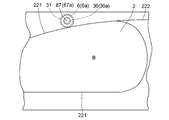
- the outer contour line 31 of the glass plate receiving surfaces 6 and 6 a is outside the area B surrounded by the planned breaking line 221 which is a cutting line of the glass plate 2 in plan view. So as to arrange the glass plate receiving surfaces 6 and 6a so that the pressing surfaces 87 and 87a can press the glass plate 2 circumscribed to the intended breaking line 221 of the plate and facing the recesses 36 and 36a.
- the motors 59 and 59a and 72 and 72a are operated to move the glass plate receiving devices 7 and 7a in the X and Y directions and the electric motors 59 and 59a and 72 and 72a are intended to be broken in plan view.
- the electric motors 114 and 114a and 135 and 135a are also operated to move the pushing surfaces 87 and 87a of the pushing devices 9 and 9a in the X and Y directions, respectively. Position each of 87a above the central portion of each of the recesses 36 and 36a.
- the recesses 36 and 36 a and the pushing surfaces 87 and 87 a face each other in the Z direction, and the elevating means 27 causes the glass plate receiving surfaces 6 and 6 a to serve as a support surface of the support mechanism 15.
- the air cylinder devices 85 and 85a are operated to lower the push rods 88 and 88a in a state of being disposed at the same height with respect to the upper surface 51 as the support surface of the support member 4 and the upper surface 51 of the
- the pressing surface is such that the pressing surfaces 87 and 87a are pressed against the glass plate 2 which is outside the region B and is surrounded by the glass plate receiving surfaces 6 and 6a, that is, the central portions of the recesses 36 and 36a respectively.
- the glass plate 2 is moved or lowered to cause the glass plate 2 to bend by pressing the pressing surfaces 87 and 87a against the glass plate 2 corresponding to the central portions of the recesses 36 and 36a, respectively.
- the glass plate 2 is pushed and split along the planned breaking line 221, and the glass plate 2 outside the region B and between the end cutting lines 222 is pushed and split from the glass plate 2 in the region B, and the push rod 88 after being cut.
- the glass plate 2 outside the area B is discharged as a split cullet by traveling in the A direction of the endless belt 3 and the above operation is cut off It does in each pressing plan aspect between 222.
- the endless belt 3 on which the glass plate 2 on which the expected fracture line 221 and the end line 222 are formed is placed, and the glass plate 2 via the endless belt 3 in the lower surface in the region B in plan view of the glass plate 2
- a support mechanism 15 having an upper surface 51 supported at its central portion, and glass plate receiving surfaces 6 and 6a for receiving the glass plate 2 from the lower surface of the glass plate 2 via the endless belt 3 and the glass plate
- Glass plate receivers 7 and 7a each having a recess 36 and 36a surrounded by the receiving surfaces 6 and 6a and disposed below the endless belt 3, and the glass plate receivers of the glass plate receivers 7 and 7a
- the moving devices 8 and 8a for moving the surfaces 6 and 6a, respectively, and the glass plate 2 on which the intended breaking line 221 and the end line 222 are formed are pushed and split along the intended breaking line 221 and the end line 222 Pressing surface 8 And 87a, and has pushing devices 9 and 9a disposed above the endless belt 3, and moving devices 10 and 10a for moving the
- each of the moving devices 8 and 8a is outside the region B surrounded by the planned breaking line 221 of the glass plate 2 in plan view when the pressing surfaces 87 and 87a respectively press and divide the glass plate 2 and the glass plate Arrange each of the glass plate receiving surfaces 6 and 6a so that the pushing surfaces 87 and 87a can press the glass plate 2 facing each of the recesses 36 and 36a surrounded by the receiving surfaces 6 and 6a
- each of the moving devices 10 and 10a is a member of each of the moving devices 8 and 8a when it is divided by the pressing surfaces 87 and 87a against the glass plate 2, respectively.
- the glass plate 2 is outside the region B surrounded by the planned breaking line 221 of the glass plate 2 in plan view and moved to the concaves 36 and 36a surrounded by the glass plate receiving surfaces 6 and 6a in plan view.
- the pressing surfaces 87 and 87a are arranged so that the pressing surfaces 87 and 87a can be pressed by the pressing surfaces 87 and 87a respectively, and the pressing devices 9 and 9a respectively receive the glass plate receiving surfaces 6 and 6a respectively.
- the pressing surfaces 87 and 87a are respectively pressed against the glass plate 2 facing the recesses 36 and 36a surrounded by the and the glass plate 2 is pushed and split along the planned breaking line 221 and the end cutting line 222.
- the collision between the split cullet outside the region B and the split surface of the glass plate 2 in the region B can be avoided, and chipping or the like may occur on the split surface of the glass plate 2 as a product after the split. It can be lost.
- the planned breaking lines 221 may be formed by the pressing devices 9 and 9a of the glass sheet breaking machine 1, and in the glass sheet breaking machine 1, the pressing lines It is also possible to perform only the process of forming the end cutting line in the previous step, and in this case, the cutter holes 92 and 92a and the like can be omitted.
- a pair of glass plate receiving devices 7 and 7a, a pair of moving devices 8 and 8a, a pair of pushing devices 9 and 9a and a pair of moving devices 10 and 10a are provided.
- the cutting line formation and the pressing and dividing are performed in a shared manner, instead of this, only one piece or three or more pieces may be provided to constitute a glass plate breaking machine.
- the electric motors 59 and 59a and 72 and 72a are operated so that the outer contour line 31 circumscribes the planned breakage line 221 of the glass plate 2 in plan view.
- the pressing rods 88 and 88a are Although each of the pressing surfaces 87 and 87a is located outside the region B in plan view and above the central portion of each of the recesses 36 and 36a, instead, as shown in FIG.
- the outer contour line 31 is apart from the intended breaking line 221 of the glass plate 2 and is outside the region B in plan view, and the glass plate receiving surfaces 6 and 6a and the recesses 36 and 36a Further, as shown in FIG. 11, the outer contour line 31 and the glass plate receiving surfaces 6 and 6 a intersect the planned breaking line 221 of the glass plate 2 so as to be located outside B, as shown in FIG.
- the glass plate receiving surfaces 6 and 6a and the recesses 36 and 36a are partially in the region B, and the remaining portions are outside the region B, and the glass plate receiving surfaces 6 and 6a are in the region B in plan view.
- Electric motors 59 and 59a and 72 and 72a are operated to move the glass plate receiving devices 7 and 7a in the X and Y directions so as to be positioned outside the central portions of the recesses 36 and 36a respectively.
- the electric motors 114 and 114a and 135 and 135a are operated to move the pressers 9 and 9a in the X and Y directions so that the push surfaces 87 and 87a of the push rods 88 and 88a are recessed 36 and 3 respectively. So as to be positioned above the respective a, it may perform split-folding.
- the glass plate receiving surfaces 6 and 6a are lifted and lowered by the lifting and lowering means 27 and 27a, respectively, the glass plate receiving surfaces 6 and 6a are always upper surfaces without providing the lifting and lowering means 27 and 27a. It may be made flush with 51.
- each of the recesses 36 and 36a may be a partial spherical recess defined by a partial concave spherical surface 232, as shown in FIG.
- the pressing surface 87 is a flat circular plane, but as shown in FIG. 13, it consists of the outer peripheral surface of a partial sphere fixed to the lower end of the pressing rod 88. It may be a partial spherical surface (fixed partial spherical surface) that does not rotate, and as shown in FIG. 14, it is a rotatable surface formed of the outer peripheral surface of a cylindrical body such as a roller rotatably supported at the lower end of piston rod 86 via a shaft. Although it is not shown in the figure, it may be a rotatable spherical surface consisting of the outer peripheral surface of a sphere rotatably supported at the lower end of the push rod 88.
- It may be a cylindrical surface fixed to the lower end of the rod 88, a cylindrical surface consisting of an outer peripheral surface of a conical body or a frusto-conical surface, a conical surface or a frusto-conical surface; , And the outer peripheral surface of the prism fixed to the lower end of the push rod 88 It may be a flat rectangular surface, and in the case where the pressing surface 87 is a rotatable cylindrical surface and a fixed cylindrical surface, the axial center O of these cylindrical surfaces is pressed by the cylindrical surface.
- the push rod 88 is rotated about the axial center 230 of the push rod 88 or the axial center 105 of the piston rod 90 so as to extend in parallel with the tangent of the planned breaking line 221 closest to the position on the upper surface (predicted position).
- a mechanism should be provided.
- the pushing surface 87 has a partial spherical or cylindrical surface or the like as shown in FIGS. 13 and 14 and the recess 36 has a partial spherical recess as shown in FIG.
- the cylindrical surface may have a radius of curvature smaller than the radius of curvature of such a partially spherical recess.
- the push rod 88 is moved in the Z direction by the expansion and contraction of the piston rod 86 to bring the push surface 87 into contact with the glass plate 2, thereby pushing and breaking the glass plate 2.
- the push rod 88 is crossed in the Z direction by the expansion and contraction of the piston rod 86 of the air cylinder device 85 which is provided by being suspended from the base 104 via the suspending member 231.
- the pushing surface 87 is made to abut against the glass plate 2 by extension of the piston rod 86, and the glass plate 2 is pushed obliquely downward by the pushing surface 87 and the glass plate 2 outside the area B is
- the glass plate 2 may be pushed apart from the glass plate 2 in the region B and kicked toward the outer edge of the glass plate 2, and in this case also, the air cylinder device 85 is suspended by the hanging member 231. of It may be provided a rotation mechanism for rotating about the axis 105 of the heart 233 or the piston rod 90.
Priority Applications (10)
| Application Number | Priority Date | Filing Date | Title |
|---|---|---|---|
| RU2019111780A RU2711095C1 (ru) | 2017-10-25 | 2018-09-26 | Устройство для ломки изгибом стеклянных пластин |
| US16/333,792 US10919795B2 (en) | 2017-10-25 | 2018-09-26 | Glass plate bend-breaking machine |
| JP2019518014A JP6544502B1 (ja) | 2017-10-25 | 2018-09-26 | ガラス板の折割機械 |
| KR1020197007545A KR102031718B1 (ko) | 2017-10-25 | 2018-09-26 | 유리판의 분할 기계 |
| BR112019008028A BR112019008028A2 (pt) | 2017-10-25 | 2018-09-26 | máquina para curvar placas de vidro |
| CN201880003559.6A CN109963819B (zh) | 2017-10-25 | 2018-09-26 | 玻璃板的折断机 |
| MX2019004104A MX2019004104A (es) | 2017-10-25 | 2018-09-26 | Maquina para romper por flexion placa de vidrio. |
| EP18852771.7A EP3666739B1 (en) | 2017-10-25 | 2018-09-26 | Glass plate splitting machine |
| TW107136703A TWI680107B (zh) | 2017-10-25 | 2018-10-18 | 玻璃板之折斷機械 |
| TW108132828A TW201945303A (zh) | 2017-10-25 | 2018-10-18 | 玻璃板之折斷機械 |
Applications Claiming Priority (2)
| Application Number | Priority Date | Filing Date | Title |
|---|---|---|---|
| JP2017-206690 | 2017-10-25 | ||
| JP2017206690 | 2017-10-25 |
Publications (1)
| Publication Number | Publication Date |
|---|---|
| WO2019082585A1 true WO2019082585A1 (ja) | 2019-05-02 |
Family
ID=66247469
Family Applications (1)
| Application Number | Title | Priority Date | Filing Date |
|---|---|---|---|
| PCT/JP2018/035819 WO2019082585A1 (ja) | 2017-10-25 | 2018-09-26 | ガラス板の折割機械 |
Country Status (10)
| Country | Link |
|---|---|
| US (1) | US10919795B2 (zh) |
| EP (1) | EP3666739B1 (zh) |
| JP (1) | JP6544502B1 (zh) |
| KR (1) | KR102031718B1 (zh) |
| CN (1) | CN109963819B (zh) |
| BR (1) | BR112019008028A2 (zh) |
| MX (1) | MX2019004104A (zh) |
| RU (1) | RU2711095C1 (zh) |
| TW (4) | TW201945302A (zh) |
| WO (1) | WO2019082585A1 (zh) |
Families Citing this family (2)
| Publication number | Priority date | Publication date | Assignee | Title |
|---|---|---|---|---|
| WO2019026586A1 (ja) * | 2017-08-01 | 2019-02-07 | 坂東機工株式会社 | ガラス板の折割機械 |
| JP6958787B2 (ja) * | 2017-10-25 | 2021-11-02 | 坂東機工株式会社 | ガラス板の折割機械 |
Citations (5)
| Publication number | Priority date | Publication date | Assignee | Title |
|---|---|---|---|---|
| JPH05221673A (ja) * | 1992-02-14 | 1993-08-31 | Taketoshi Nojima | 割断加工方法 |
| JPH08217475A (ja) | 1995-02-07 | 1996-08-27 | Bando Kiko Kk | ガラス板の加工装置 |
| WO2000012439A1 (fr) * | 1998-08-28 | 2000-03-09 | Bando Kiko Co., Ltd. | Machine d'enclenchement de plaque de verre |
| JP2012071365A (ja) * | 2010-09-28 | 2012-04-12 | Casio Computer Co Ltd | 基板切断装置及び基板切断方法 |
| JP2016040079A (ja) * | 2014-08-12 | 2016-03-24 | 三星ダイヤモンド工業株式会社 | 脆性材料基板の分断方法及び分断装置 |
Family Cites Families (18)
| Publication number | Priority date | Publication date | Assignee | Title |
|---|---|---|---|---|
| US2078386A (en) * | 1935-11-29 | 1937-04-27 | Michael B Kendis | Glass cutting mechanism |
| FR1290194A (fr) * | 1961-02-23 | 1962-04-13 | Saint Gobain | Machine pour tracer et rompre des panneaux en verre |
| SU528268A1 (ru) * | 1974-07-17 | 1976-09-15 | Одесский Проектно-Конструкторский И Экспериментальный Филиал Всесоюзного Научно-Исследовательского И Проектно-Конструкторского Института Стекольного Машиностроения | Устройство дл отделени бортов от непрерывной ленты стекла и их дроблени |
| DE2504107C3 (de) * | 1975-01-31 | 1981-05-27 | Borskij Stekol'nyj zavod imeni M. Gor'kogo, Bor, Gorkovskaja oblst' | Vorrichtung zum Abtrennen des Grates von einer Glastafel |
| SU1350120A1 (ru) * | 1986-03-26 | 1987-11-07 | Белорусский Научно-Исследовательский И Проектно-Технологический Институт Организации И Управления Строительством Госстроя Бсср | Устройство дл разделени листов стекла |
| JPH0725633A (ja) * | 1993-07-09 | 1995-01-27 | Kanegafuchi Chem Ind Co Ltd | ガラス基板の折割り方法及びその装置 |
| JPH1095626A (ja) * | 1996-09-18 | 1998-04-14 | Tokai Rika Co Ltd | 曲面ガラス切断機 |
| DE19708385A1 (de) * | 1997-03-01 | 1998-09-03 | Deutsche Telekom Ag | Wellenlängenabstimmbares optoelektronisches Bauelement |
| JPH11116261A (ja) | 1997-10-09 | 1999-04-27 | Ishizuka Glass Co Ltd | ガラスの加工方法 |
| JP4342039B2 (ja) * | 1999-06-15 | 2009-10-14 | 三星ダイヤモンド工業株式会社 | ガラススクライバー及びスクライブ方法 |
| EP1647534B1 (de) * | 2004-10-15 | 2018-12-19 | Bystronic Maschinen AG | Vorrichtung und Verfahren zum Brechen von Glasscheiben |
| JP5285736B2 (ja) * | 2011-04-06 | 2013-09-11 | 三星ダイヤモンド工業株式会社 | 脆性材料基板の内周加工方法 |
| JP5796774B2 (ja) * | 2011-08-24 | 2015-10-21 | 日本電気硝子株式会社 | 脆性板材の割断方法と割断装置 |
| JP6071024B2 (ja) * | 2013-02-25 | 2017-02-01 | コーニング インコーポレイテッド | 薄いガラス板を製造する方法 |
| JP5800011B2 (ja) | 2013-12-09 | 2015-10-28 | 坂東機工株式会社 | ガラス板の折割機械 |
| JP2016104683A (ja) * | 2014-11-19 | 2016-06-09 | 坂東機工株式会社 | ガラス板の折割方法及びその折割装置 |
| EP3222593B1 (en) * | 2014-11-19 | 2022-06-29 | Bando Kiko Co., Ltd | Method for splitting glass plate |
| JP2017170757A (ja) * | 2016-03-24 | 2017-09-28 | 三星ダイヤモンド工業株式会社 | 分断装置 |
-
2018
- 2018-08-03 TW TW108131677A patent/TW201945302A/zh unknown
- 2018-08-03 TW TW107127043A patent/TWI680951B/zh active
- 2018-09-26 WO PCT/JP2018/035819 patent/WO2019082585A1/ja unknown
- 2018-09-26 EP EP18852771.7A patent/EP3666739B1/en active Active
- 2018-09-26 CN CN201880003559.6A patent/CN109963819B/zh active Active
- 2018-09-26 BR BR112019008028A patent/BR112019008028A2/pt not_active Application Discontinuation
- 2018-09-26 MX MX2019004104A patent/MX2019004104A/es unknown
- 2018-09-26 JP JP2019518014A patent/JP6544502B1/ja active Active
- 2018-09-26 US US16/333,792 patent/US10919795B2/en active Active
- 2018-09-26 KR KR1020197007545A patent/KR102031718B1/ko active IP Right Grant
- 2018-09-26 RU RU2019111780A patent/RU2711095C1/ru active
- 2018-10-18 TW TW107136703A patent/TWI680107B/zh active
- 2018-10-18 TW TW108132828A patent/TW201945303A/zh unknown
Patent Citations (5)
| Publication number | Priority date | Publication date | Assignee | Title |
|---|---|---|---|---|
| JPH05221673A (ja) * | 1992-02-14 | 1993-08-31 | Taketoshi Nojima | 割断加工方法 |
| JPH08217475A (ja) | 1995-02-07 | 1996-08-27 | Bando Kiko Kk | ガラス板の加工装置 |
| WO2000012439A1 (fr) * | 1998-08-28 | 2000-03-09 | Bando Kiko Co., Ltd. | Machine d'enclenchement de plaque de verre |
| JP2012071365A (ja) * | 2010-09-28 | 2012-04-12 | Casio Computer Co Ltd | 基板切断装置及び基板切断方法 |
| JP2016040079A (ja) * | 2014-08-12 | 2016-03-24 | 三星ダイヤモンド工業株式会社 | 脆性材料基板の分断方法及び分断装置 |
Non-Patent Citations (1)
| Title |
|---|
| See also references of EP3666739A4 |
Also Published As
| Publication number | Publication date |
|---|---|
| RU2711095C1 (ru) | 2020-01-15 |
| JPWO2019082585A1 (ja) | 2019-11-14 |
| CN109963819A (zh) | 2019-07-02 |
| TW201917104A (zh) | 2019-05-01 |
| EP3666739A1 (en) | 2020-06-17 |
| EP3666739B1 (en) | 2022-04-27 |
| TW201945302A (zh) | 2019-12-01 |
| TWI680107B (zh) | 2019-12-21 |
| KR20190051982A (ko) | 2019-05-15 |
| TWI680951B (zh) | 2020-01-01 |
| CN109963819B (zh) | 2022-04-01 |
| JP6544502B1 (ja) | 2019-07-17 |
| TW201922644A (zh) | 2019-06-16 |
| TW201945303A (zh) | 2019-12-01 |
| BR112019008028A2 (pt) | 2020-04-28 |
| US10919795B2 (en) | 2021-02-16 |
| MX2019004104A (es) | 2019-07-15 |
| US20190256397A1 (en) | 2019-08-22 |
| KR102031718B1 (ko) | 2019-10-14 |
| EP3666739A4 (en) | 2021-05-12 |
Similar Documents
| Publication | Publication Date | Title |
|---|---|---|
| JP4449084B2 (ja) | ガラス板の折割機械 | |
| JP6544502B1 (ja) | ガラス板の折割機械 | |
| JP5800011B2 (ja) | ガラス板の折割機械 | |
| JP6544493B2 (ja) | ガラス板の折割機械 | |
| JP6958787B2 (ja) | ガラス板の折割機械 | |
| JP6944636B2 (ja) | ガラス板の折割機械 | |
| WO2020084840A1 (ja) | ガラス板の折割機械 | |
| JP4998535B2 (ja) | ガラス板の折割機械 | |
| JP5609794B2 (ja) | ガラス板の折割機械 | |
| JP2015129090A (ja) | ガラス板の折割機械 |
Legal Events
| Date | Code | Title | Description |
|---|---|---|---|
| ENP | Entry into the national phase |
Ref document number: 20197007545 Country of ref document: KR Kind code of ref document: A |
|
| ENP | Entry into the national phase |
Ref document number: 2019518014 Country of ref document: JP Kind code of ref document: A |
|
| REG | Reference to national code |
Ref country code: BR Ref legal event code: B01A Ref document number: 112019008028 Country of ref document: BR |
|
| ENP | Entry into the national phase |
Ref document number: 112019008028 Country of ref document: BR Kind code of ref document: A2 Effective date: 20190418 |
|
| NENP | Non-entry into the national phase |
Ref country code: DE |
|
| ENP | Entry into the national phase |
Ref document number: 2018852771 Country of ref document: EP Effective date: 20190404 |
|
| 121 | Ep: the epo has been informed by wipo that ep was designated in this application |
Ref document number: 18852771 Country of ref document: EP Kind code of ref document: A1 |