WO2019077802A1 - 脱気装置 - Google Patents
脱気装置 Download PDFInfo
- Publication number
- WO2019077802A1 WO2019077802A1 PCT/JP2018/023551 JP2018023551W WO2019077802A1 WO 2019077802 A1 WO2019077802 A1 WO 2019077802A1 JP 2018023551 W JP2018023551 W JP 2018023551W WO 2019077802 A1 WO2019077802 A1 WO 2019077802A1
- Authority
- WO
- WIPO (PCT)
- Prior art keywords
- flow path
- degassing
- mobile phase
- channel
- switching unit
- Prior art date
- Legal status (The legal status is an assumption and is not a legal conclusion. Google has not performed a legal analysis and makes no representation as to the accuracy of the status listed.)
- Ceased
Links
Images






Classifications
-
- B—PERFORMING OPERATIONS; TRANSPORTING
- B01—PHYSICAL OR CHEMICAL PROCESSES OR APPARATUS IN GENERAL
- B01D—SEPARATION
- B01D19/00—Degasification of liquids
- B01D19/0036—Flash degasification
-
- B—PERFORMING OPERATIONS; TRANSPORTING
- B01—PHYSICAL OR CHEMICAL PROCESSES OR APPARATUS IN GENERAL
- B01D—SEPARATION
- B01D15/00—Separating processes involving the treatment of liquids with solid sorbents; Apparatus therefor
- B01D15/08—Selective adsorption, e.g. chromatography
- B01D15/10—Selective adsorption, e.g. chromatography characterised by constructional or operational features
- B01D15/16—Selective adsorption, e.g. chromatography characterised by constructional or operational features relating to the conditioning of the fluid carrier
- B01D15/166—Fluid composition conditioning, e.g. gradient
-
- B—PERFORMING OPERATIONS; TRANSPORTING
- B01—PHYSICAL OR CHEMICAL PROCESSES OR APPARATUS IN GENERAL
- B01D—SEPARATION
- B01D19/00—Degasification of liquids
- B01D19/0031—Degasification of liquids by filtration
-
- B—PERFORMING OPERATIONS; TRANSPORTING
- B01—PHYSICAL OR CHEMICAL PROCESSES OR APPARATUS IN GENERAL
- B01D—SEPARATION
- B01D19/00—Degasification of liquids
- B01D19/0063—Regulation, control including valves and floats
-
- B—PERFORMING OPERATIONS; TRANSPORTING
- B01—PHYSICAL OR CHEMICAL PROCESSES OR APPARATUS IN GENERAL
- B01D—SEPARATION
- B01D61/00—Processes of separation using semi-permeable membranes, e.g. dialysis, osmosis or ultrafiltration; Apparatus, accessories or auxiliary operations specially adapted therefor
-
- B—PERFORMING OPERATIONS; TRANSPORTING
- B01—PHYSICAL OR CHEMICAL PROCESSES OR APPARATUS IN GENERAL
- B01D—SEPARATION
- B01D65/00—Accessories or auxiliary operations, in general, for separation processes or apparatus using semi-permeable membranes
- B01D65/02—Membrane cleaning or sterilisation ; Membrane regeneration
- B01D65/06—Membrane cleaning or sterilisation ; Membrane regeneration with special washing compositions
-
- G—PHYSICS
- G01—MEASURING; TESTING
- G01N—INVESTIGATING OR ANALYSING MATERIALS BY DETERMINING THEIR CHEMICAL OR PHYSICAL PROPERTIES
- G01N30/00—Investigating or analysing materials by separation into components using adsorption, absorption or similar phenomena or using ion-exchange, e.g. chromatography or field flow fractionation
- G01N30/02—Column chromatography
- G01N30/26—Conditioning of the fluid carrier; Flow patterns
- G01N30/28—Control of physical parameters of the fluid carrier
- G01N30/32—Control of physical parameters of the fluid carrier of pressure or speed
-
- G—PHYSICS
- G01—MEASURING; TESTING
- G01N—INVESTIGATING OR ANALYSING MATERIALS BY DETERMINING THEIR CHEMICAL OR PHYSICAL PROPERTIES
- G01N30/00—Investigating or analysing materials by separation into components using adsorption, absorption or similar phenomena or using ion-exchange, e.g. chromatography or field flow fractionation
- G01N30/02—Column chromatography
- G01N30/26—Conditioning of the fluid carrier; Flow patterns
- G01N30/28—Control of physical parameters of the fluid carrier
- G01N30/34—Control of physical parameters of the fluid carrier of fluid composition, e.g. gradient
-
- G—PHYSICS
- G01—MEASURING; TESTING
- G01N—INVESTIGATING OR ANALYSING MATERIALS BY DETERMINING THEIR CHEMICAL OR PHYSICAL PROPERTIES
- G01N30/00—Investigating or analysing materials by separation into components using adsorption, absorption or similar phenomena or using ion-exchange, e.g. chromatography or field flow fractionation
- G01N30/02—Column chromatography
- G01N2030/022—Column chromatography characterised by the kind of separation mechanism
- G01N2030/027—Liquid chromatography
Definitions
- the present invention relates to a degassing apparatus used for degassing, for example, a mobile phase fed in an analysis channel of high performance liquid chromatograph (hereinafter, HPLC).
- HPLC high performance liquid chromatograph
- a degassing device is disposed upstream of the liquid feed pump on the flow path of the mobile phase, and the mobile phase solvent is generally degassed by the degassing device (see Patent Document 1). ).
- a degassing flow path consisting of a gas permeable tube which passes gas and does not pass liquid is provided in a closed space called a vacuum chamber, and the pressure in the vacuum chamber is reduced by a vacuum pump to It is configured to extract gas components from the flowing liquid and discharge it to the outside of the vacuum chamber (see Patent Document 2).
- the liquid transfer pump is stopped to stop the flow of the mobile phase, and the mobile phase is retained in the degassing flow path of the degassing device. If such a condition is maintained for a long time without the next analysis being started, the mobile phase in the degassing flow path is vaporized and permeates the gas permeable tube to stay in the vacuum chamber or the vacuum pump.
- solvents used as the mobile phase. For example, in GPC (gel permeation chromatography) analysis, a solvent having high solvency such as chloroform is used. If such solvent evaporates and stays in the vacuum chamber or vacuum pump, the components in the degassing device may be damaged such as corrosion or swelling.
- an object of the present invention is to prevent the retention of the vaporized mobile phase in the degassing device.
- the degassing apparatus is provided on the flow path of the mobile phase fed by the liquid feed pump to degas the mobile phase.
- the degassing apparatus includes a degassing flow path, a vacuum chamber, a vacuum pump, an inlet flow path, an outlet flow path, a drain flow path, a downstream switching unit, and a control unit.
- the degassing flow path is made of a gas permeable tube which is gas permeable and liquid impermeable, and is accommodated in the vacuum chamber.
- the vacuum pump is connected to the vacuum chamber to decompress the inside of the vacuum chamber.
- the inlet channel is for guiding the mobile phase to the degassing channel, and the outlet channel is for discharging the mobile phase passing through the degassing channel.
- the drain flow channel is provided separately from the outlet flow channel, and is for discharging the mobile phase in the degassing flow channel from the degassing flow channel.
- the downstream switching unit is configured to switch and connect the downstream end of the degassing channel to either the outlet channel or the drain channel.
- the control unit controls the operation of the downstream side switching unit, and the downstream end of the degassing flow passage is set to the drain flow passage at a predetermined timing at which the transfer of the mobile phase by the liquid transfer pump is stopped. It connects, and it is comprised so that the mobile phase in the said degassing flow path may be discharged
- the inside of the degassing flow path is stopped at a predetermined timing at which the feeding of the mobile phase by the liquid feeding pump is stopped, for example, at a timing when a series of scheduled analysis operations is finished
- the mobile phase is discharged through the drain channel. This prevents the mobile phase from staying in the degassing channel for a long period of time.
- the air release flow path whose upstream end is released to the atmosphere, and the upstream end of the degassing flow path are switched and connected to either the inlet flow path or the air release flow path.
- a configured upstream switching unit In that case, the control unit controls the operation of the downstream switching unit and the upstream switching unit, and the upstream end of the degassing flow passage when the downstream end of the degassing flow passage is connected to the outlet flow passage. The end is connected to the inlet flow path, and the upstream end of the degassing flow path is connected to the air release flow path when the downstream end of the degassing flow path is connected to the drain flow path.
- the cleaning liquid supply flow path for supplying the cleaning liquid to the degassing flow path, and the upstream end of the degassing flow path is either the inlet flow path or the cleaning liquid supply flow path. It may further include an upstream switching unit configured to switch to and connect to.
- the control unit controls the operation of the downstream switching unit and the upstream switching unit, and the upstream end of the degassing flow passage when the downstream end of the degassing flow passage is connected to the outlet flow passage.
- the end is connected to the inlet flow path, and the upstream end of the degassing flow path is connected to the cleaning liquid supply flow path when the downstream end of the degassing flow path is connected to the drain flow path.
- the control unit may also be configured to control the operation of the vacuum pump and operate the vacuum pump for a predetermined time after the mobile phase in the degassing flow path is discharged through the drain flow path. . Then, after the mobile phase is discharged from the inside of the degassing flow path, the vaporized gas of the mobile phase existing in the vacuum chamber or the vacuum pump can be discharged to the outside.
- the scheduled series of analyzes are all completed, and then, depending on the solvent, delivery of the mobile phase is not started over a certain period (more than one day particularly for highly corrosive solvents). It is assumed that the mobile phase does not stay in the degassing channel for such a long period of time. That is, the present invention is not intended to discharge the mobile phase in the degassing channel through the drain channel every time one analysis is completed.
- the present invention is not intended to discharge the mobile phase in the degassing channel through the drain channel every time one analysis is completed.
- control unit is configured to stop the operation of the vacuum pump when liquid feeding of the mobile phase by the liquid feeding pump is stopped. Then, it is possible to suppress the consumption of the mobile phase when the mobile phase supply by the liquid feed pump is stopped, that is, when the analysis is not performed.
- the apparatus further comprises a flow rate sensor for detecting the flow rate of the mobile phase flowing through the outlet flow path, and the control unit operates the vacuum pump when the flow rate of the mobile phase detected by the flow rate sensor is zero. May be configured to stop the Then, the flow rate sensor can automatically detect whether the liquid feed pump is operating.
- this invention is not limited to this, The said control part receives the signal about whether it is working from the said liquid feeding pump, It is stopped whether the operation
- the mobile phase in the degassing flow path is discharged through the drain flow path at a predetermined timing at which the transfer of the mobile phase by the liquid transfer pump is stopped. Therefore, the mobile phase does not stay in the degassing flow channel for a long period of time, and corrosion and swelling of parts in the degassing apparatus can be suppressed.
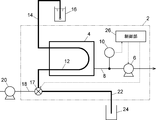
- the degassing apparatus 2 of this embodiment mainly includes a vacuum chamber 4, a vacuum pump 6, a degassing flow path 12, a downstream switching unit 17, and a control unit 26.
- the vacuum chamber 4 has an enclosed space inside, and the degassing flow path 12 is accommodated in the enclosed space.
- the vacuum pump 6 is in fluid communication with the enclosed space in the vacuum chamber 4 via the vacuum flow path 8, and the pressure in the vacuum chamber 4 is reduced by the vacuum pump 6.
- a pressure sensor 10 for detecting the pressure in the vacuum flow passage 8 is provided, and a detection signal of the pressure sensor 10 is taken into the control unit 26.
- the control unit 26 is configured to control the operation of the vacuum pump 6 based on the detection signal of the pressure sensor 10 so that the pressure in the vacuum chamber 4 becomes a preset pressure.
- the degassing flow passage 12 is a flow passage made of a gas permeable tube which allows gas to pass and does not allow liquid to pass.
- the upstream end of the degassing flow passage 12 is in fluid communication with the inlet flow passage 14 leading to the container 16 containing the mobile phase, and the downstream end of the degassing flow passage 12 is connected to one connection port of the downstream switching unit 17 ing.
- the downstream switching unit 17 is realized by a three-way solenoid valve having three connection ports.
- the outlet flow path 18 and the drain flow path 22 are connected to the remaining two connection ports of the downstream side switching unit 17.
- the downstream switching unit 17 is configured to place the downstream end of the degassing passage 12 in fluid communication with either the outlet passage 18 or the drain passage 22.
- the outlet flow path 18 is a flow path leading to the liquid feed pump 20 for feeding the mobile phase.
- the drain flow path 22 is a flow path for discharging the mobile phase in the degassing flow path 12 from the degassing flow path 12, and the downstream end is in communication with the waste liquid bottle 24.
- the operation of the downstream side switching unit 17 is also controlled by the control unit 26.
- the control unit 26 is realized by an arithmetic element such as a microcomputer and a predetermined program executed by the arithmetic element.
- a signal is input to the control unit 26 from an external device, such as a system controller that controls the entire system of HPLC, and the operation of the downstream switching unit 17 is controlled based on the signal. It is configured.
- control unit 26 causes the downstream switching unit 17 to connect the downstream end of the degassing channel 12 and the outlet channel 18. Thereby, as shown in FIG. 2, the mobile phase of the mobile phase container 16 flows to the outlet channel 18 through the degassing channel 12.
- the control unit 26 controls the downstream switching unit 17 at the downstream end of the degassing flow path 12 and the drain flow path at a predetermined timing at which the transfer of the mobile phase by the liquid transfer pump 20 stops, for example, a timing at which a series of analysis operations end. 22 and the connection state.
- the downstream end of the drain channel 22 is disposed at a lower position than the downstream ends of the mobile phase container 16 and the degassing channel 12, and when the downstream end of the degassing channel 12 is connected to the drain channel 22, as shown in FIG. As shown in FIG. 1, the mobile phase in the degassing channel 12 and in the mobile phase container 16 is drained to the waste bottle 24 through the drain channel 22. Thus, the mobile phase does not stay in the degassing flow path 12 for a long time after the series of analysis operations are completed.
- FIG. 4 shows another embodiment of the degassing apparatus.
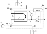
- the degassing device 2 a of this embodiment includes an air release flow channel 30 whose upstream end is released to the air, and the upstream switching realized by a three-way solenoid valve By switching the portion 28, the upstream end of the degassing flow passage 12 is configured to be selectively connected to either the inlet flow passage 14 or the atmosphere release flow passage 30.
- the operation of the upstream switching unit 28 is controlled by the control unit 26a.
- control unit 26a connects the downstream switching unit 17 to the downstream end of the degassing flow passage 12 and the outlet flow passage 18 and connects the upstream switching unit 28 to the upstream end of the degassing flow passage 12 It is configured to connect with the inlet channel 14. Thereby, as shown in FIG. 5, the mobile phase of the mobile phase container 16 flows to the outlet channel 18 through the degassing channel 12.
- the control unit 26a controls the downstream switching unit 17 to the downstream end of the degassing flow passage 12 and the drain flow passage.
- the upstream switching unit 28 is configured to connect the upstream end of the degassing flow passage 12 to the atmosphere release flow passage 30 as well as to connect the air flow passage 22.
- the inlet flow passage 14 communicating with the mobile phase container 16 is blocked from the degassing flow passage 12, even after the series of analysis operations are completed.
- the mobile phase in the mobile phase container 16 can be left, and consumption of the mobile phase can be suppressed.
- FIG. 7 shows still another embodiment of the degassing apparatus.
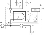
- the degassing device 2b of this embodiment includes a cleaning fluid flow path 32 leading to a cleaning fluid container 34 containing a cleaning fluid (for example, isopropyl alcohol), instead of the atmosphere release flow path 30 of the degassing device 2a of FIG.
- a cleaning solution pump 36 is provided on the drain flow channel 36.
- the upstream end of the degassing passage 12 is selectively connected to one of the inlet passage 14 and the cleaning solution supply passage 32 by switching of the upstream switching unit 28.
- the operations of the upstream switching unit 28 and the cleaning solution pump 36 are controlled by the control unit 26 b.
- control unit 26 b connects the downstream end of the degassing flow passage 12 and the outlet flow passage 18 with the downstream switching unit 17, and the upstream switching unit 28 as the upstream end of the degassing flow passage 12. And the inlet channel 14 are connected. Thereby, as shown in FIG. 8, the mobile phase of the mobile phase container 16 flows to the outlet channel 18 through the degassing channel 12.
- the control unit 26b controls the downstream switching unit 17 to the downstream end of the degassing flow path 12 and the drain flow path
- the upstream switching unit 28 is configured to connect the upstream end of the degassing flow path 12 and the cleaning liquid supply flow path 32 and to operate the cleaning liquid pump 36.
- the upstream end of the degassing flow path 12 is connected to the cleaning liquid supply flow path 32, and the cleaning liquid is discharged to the waste liquid bottle 24 through the degassing flow path 12 and the drain flow path 22.
- the upstream end of the degassing flow path 12 is connected to the cleaning liquid supply flow path 32, so that the inlet flow path 14 communicating with the mobile phase container 16 is blocked from the degassing flow path 12, so even after a series of analysis operations are completed.
- the mobile phase in the mobile phase container 16 can be left, and consumption of the mobile phase can be suppressed.
- the cleaning liquid from the cleaning liquid supply flow path 32 flows in the degassing flow path 12, the inside of the degassing flow path 12 can be cleaned at the same time.
- a signal to that effect is input to the control units 26, 26a, 26b of the degassing devices 2, 2a, 2b.
- the control sections 26, 26a, 26b receive the signal, and a flow path for discharging the mobile phase in the degassing flow path 12 (flow path shown by thick lines in FIG. 3, FIG. 6, FIG. 9) is configured.
- the downstream switching unit 17 and the upstream switching unit 28) is switched to discharge the mobile phase in the degassing channel 12 to the waste liquid bottle 24 (step S1).
- the vacuum pump 6 may be operating or may be stopped.
- the vacuum pump 6 is operated for a predetermined time to discharge the gas in the vacuum chamber 4 and the vacuum flow channel 8 and the vacuum pump 6 to the outside (Step S2 ). Thereafter, the operation of the vacuum pump 6 is stopped to end the maintenance operation (step S3).
- FIG. 11 shows still another embodiment of the degassing apparatus.
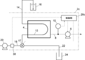
- the deaerator 2c of the embodiment is provided with a flow meter 38 on the outlet flow path 18 of the deaerator 2 of FIG. 1, and the controller 26c controls the vacuum pump 6 based on the signal from the flow meter 38.
- the control unit 26c detects the presence or absence of the operation of the liquid feeding pump 20 based on the signal from the flow meter 38, and stops the operation of the vacuum pump 6 when a predetermined time has elapsed since the liquid feeding pump 20 was stopped. Is configured as.
- the liquid feed pump 20 is stopped in this embodiment does not mean that "the series of analysis operations has been completed” in the above embodiment, but it is set to perform a plurality of analyses. It is assumed that the liquid feed pump 20 is stopped for a predetermined time or more between analysis and analysis. Therefore, the operation of the vacuum pump 6 is stopped during a series of analysis operations and not during the above-mentioned "maintenance operation" when a predetermined time has elapsed since the liquid feed pump 20 was stopped.
- the operation of the vacuum pump 6 is stopped when a predetermined time has elapsed since the liquid transfer pump 20 was stopped.
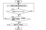
- the control unit 26c periodically takes in the detection signal of the flow meter 38 (step S11), and in each case, determines whether the flow rate of the mobile phase in the outlet flow passage 18 is 0 (step S12). Then, when the state in which the flow rate of the mobile phase in the outlet flow path 18 is 0 continues for a predetermined time (step S13), the operation of the vacuum pump 6 is stopped (step S14).
- the flow meter 38 is not an essential component for detecting the stop of the liquid feed pump 20.
- the control unit 26c may receive a signal indicating that the operation of the liquid transfer pump 20 has stopped from the HPLC system controller, or the control unit 26c may directly receive a signal regarding the operating state from the liquid transfer pump 20. You may receive it.
- the degassing device 2c shown in FIG. 11 is based on the degassing device 2 of FIG. 1, the present invention is not limited to this, and the degassing device 2a of FIG.
- the degassing device 2c of No. 7 may have a function of stopping the operation of the vacuum pump 6 when a predetermined time has elapsed since the liquid feed pump 20 was stopped.
Landscapes
- Chemical & Material Sciences (AREA)
- Chemical Kinetics & Catalysis (AREA)
- Analytical Chemistry (AREA)
- Life Sciences & Earth Sciences (AREA)
- Physics & Mathematics (AREA)
- Health & Medical Sciences (AREA)
- Biochemistry (AREA)
- General Health & Medical Sciences (AREA)
- General Physics & Mathematics (AREA)
- Immunology (AREA)
- Pathology (AREA)
- Engineering & Computer Science (AREA)
- Water Supply & Treatment (AREA)
- Degasification And Air Bubble Elimination (AREA)
Abstract
脱気装置は、脱気流路、真空チャンバ、真空ポンプ、入口流路、出口流路、ドレイン流路、下流側切替部、及び制御部を備えている。前記脱気流路は、液体を通さない気体透過性チューブからなり、前記真空チャンバ内に収容されている。前記入口流路は前記脱気流路へ移動相を導くものであり、前記出口流路は前記脱気流路を経た移動相を流出させるものである。前記ドレイン流路は、前記出口流路とは別に設けられ、前記脱気流路内の移動相を前記脱気流路から流出させるものである。前記下流側切替部は、前記脱気流路の下流端を前記出口流路又は前記ドレイン流路のいずれかへ切り替えて接続するように構成されたものである。前記制御部は前記下流側切替部の動作を制御するものであり、前記送液ポンプによる移動相の送液が停止される所定のタイミングで前記脱気流路の下流端を前記ドレイン流路に接続し、移動相を前記ドレイン流路を通じて排出するように構成されている。
Description
本発明は、例えば高速液体クロマトグラフ(以下、HPLC)の分析流路中で送液される移動相を脱気するために用いられる脱気装置に関するものである。
HPLCでは、移動相に含まれる溶存酸素や微小な気泡は送液ポンプの送液不良や流量変動、検出器のベースライン変動やノイズ、検出感度の低下など様々な問題の要因となることが知られている。そのため、移動相の流通経路上における送液ポンプよりも上流側に脱気装置を配置し、移動相溶媒を脱気装置によって脱気することが一般的に行なわれている(特許文献1を参照。)。
脱気装置は、気体を通過させ液体を通過させない気体透過性チューブからなる脱気流路が真空チャンバと呼ばれる密閉空間内に設けられ、真空チャンバ内を真空ポンプによって減圧することで、脱気流路を流れる液体から気体成分を抽出し、真空チャンバの外側へ排出するように構成されている(特許文献2を参照。)。
HPLCでは、所定の分析が終了すると送液ポンプが停止して移動相の流れが止まり、脱気装置の脱気流路内に移動相が滞留する。次の分析が開始されないまま長時間にわたってこのような状態が維持されると、脱気流路内の移動相が気化して気体透過性チューブを透過して真空チャンバ内や真空ポンプ内に留まる。移動相として用いられる溶媒には様々なものがあり、例えばGPC(ゲル浸透クロマトグラフィー)分析では、クロロホルムなどの溶解力の強い溶媒が使用される。そのような溶媒が気化して真空チャンバ内や真空ポンプ内に留まると、脱気装置内の部品に腐食や膨潤といったダメージを与えることになる。
そこで、本発明は、気化した移動相が脱気装置内に滞留することを防止することを目的とするものである。
本発明に係る脱気装置は、送液ポンプにより送液される移動相の流通経路上に設けられて移動相の脱気を行なうためのものである。当該脱気装置は、脱気流路、真空チャンバ、真空ポンプ、入口流路、出口流路、ドレイン流路、下流側切替部、及び制御部を備えている。前記脱気流路は、気体を通し液体を通さない気体透過性チューブからなるものであり、前記真空チャンバ内に収容されている。前記真空ポンプは、前記真空チャンバに接続されて前記真空チャンバ内を減圧するためのものである。前記入口流路は前記脱気流路へ移動相を導くためのものであり、前記出口流路は前記脱気流路を経た移動相を流出させるためのものである。前記ドレイン流路は、前記出口流路とは別に設けられ、前記脱気流路内の移動相を前記脱気流路から流出させるためのものである。前記下流側切替部は、前記脱気流路の下流端を前記出口流路又は前記ドレイン流路のいずれかへ切り替えて接続するように構成されたものである。前記制御部は前記下流側切替部の動作を制御するものであって、前記送液ポンプによる移動相の送液が停止される所定のタイミングで前記脱気流路の下流端を前記ドレイン流路に接続し、前記脱気流路内の移動相を前記ドレイン流路を通じて排出するように構成されている。
すなわち、本発明に係る脱気装置は、前記送液ポンプによる移動相の送液が停止される所定のタイミング、例えば、予定されていた一連の分析動作が終了したタイミングで、前記脱気流路内の移動相を前記ドレイン流路を通じて排出するように構成されている。これにより、前記脱気流路内に長期間にわたって移動相が滞留することがなくなる。
本発明に係る脱気装置は、上流端が大気解放された大気解放流路と、前記脱気流路の上流端を前記入口流路又は前記大気解放流路のいずれかへ切り替えて接続するように構成された上流側切替部と、をさらに備えていてもよい。その場合、前記制御部は、前記下流側切替部と前記上流側切替部の動作を制御し、前記脱気流路の下流端を前記出口流路と接続しているときに前記脱気流路の上流端を前記入口流路と接続し、前記脱気流路の下流端を前記ドレイン流路と接続しているときに前記脱気流路の上流端を前記大気解放流路と接続するように構成されている。このような構成にすることで、前記脱気流路内の移動相を前記ドレイン流路から排出する際に、移動相が収容されている移動相容器へ通じる前記入口流路を前記脱気流路から遮断することができ、前記脱気流路内の移動相のみを前記ドレイン流路から排出することができる。これにより、移動相容器内の移動相を排出することなく残しておくことができる。
また、本発明に係る脱気装置は、前記脱気流路へ洗浄液を供給するための洗浄液供給流路と、前記脱気流路の前記上流端を前記入口流路又は前記洗浄液供給流路のいずれかへ切り替えて接続するように構成された上流側切替部をさらに備えていてもよい。その場合、前記制御部は、前記下流側切替部と前記上流側切替部の動作を制御し、前記脱気流路の下流端を前記出口流路と接続しているときに前記脱気流路の上流端を前記入口流路と接続し、前記脱気流路の下流端を前記ドレイン流路と接続しているときに前記脱気流路の上流端を前記洗浄液供給流路と接続するように構成されている。このような構成にすることで、前記脱気流路内の移動相を前記ドレイン流路から排出する際に、移動相が収容されている移動相容器へ通じる前記入口流路を前記脱気流路から遮断するとともに、前記脱気流路内に洗浄液を流して前記脱気流路内の洗浄を行なうことができる。
前記制御部は、真空ポンプの動作も制御し、前記脱気流路内の移動相が前記ドレイン流路を通じて排出された後で、前記真空ポンプを所定時間だけ動作させるように構成されていてもよい。そうすれば、前記脱気流路内から移動相が排出された後、前記真空チャンバ内や前記真空ポンプ内に存在する移動相の気化ガスを外部へ排出することができる。
上記各態様は、予定されていた一連の分析が全て終了し、その後、溶媒にもよるが一定期間(特に腐食性の高い溶媒については1日以上)にわたって移動相の送液が開始されないような場合を想定したものであり、そのような長期間にわたって前記脱気流路内に移動相が滞留することがないようにするものである。すなわち、本発明は、1回の分析が終了するごとに前記ドレイン流路を通じて前記脱気流路内の移動相を排出することを意図したものではない。複数の分析が予定されている場合に、各分析が終了するごとに前記脱気流路内の移動相を排出していると、移動相を無駄に消費してしまい、ランニングコストの上昇を招くことになる。
一方で、複数回の分析が予定されているものの、ある分析が終了してから次の分析が開始されるまでの間に一定の時間を要するような場合に、前記真空ポンプを駆動し続けると、前記脱気流路内の移動相の気化が促進されて排出されてしまい、移動相が無駄に消費されることになる。そこで、前記制御部は、前記送液ポンプによる移動相の送液が停止しているときに前記真空ポンプの動作も停止させるように構成されていることが好ましい。そうすれば、前記送液ポンプによる移動相の送液が停止しているとき、すなわち分析が行われていないときの移動相の消費を抑制することができる。
上記の場合、前記出口流路を流れる移動相の流量を検出する流量センサをさらに備え、前記制御部は、前記流量センサにより検出される移動相の流量がゼロであるときに前記真空ポンプの動作を停止させるように構成されているようにしてもよい。そうすれば、前記流量センサによって前記送液ポンプが稼働しているか否かを自動的に検知することができる。なお、本発明はこれに限定されるものではなく、前記制御部は、前記送液ポンプから稼働中であるか否かについての信号を受けて、前記真空ポンプの動作を停止させるか否かを判断するようにしてもよい。
本発明に係る脱気装置では、前記送液ポンプによる移動相の送液が停止される所定のタイミングで、前記脱気流路内の移動相を前記ドレイン流路を通じて排出するように構成されているので、前記脱気流路内に長期間にわたって移動相が滞留することがなくなり、脱気装置内の部品の腐食や膨潤を抑制することができる。
以下、本発明に係る脱気装置の実施形態について、図面を参照しながら説明する。
脱気装置の一実施例について、図1を用いて説明する。
この実施例の脱気装置2は、主として、真空チャンバ4、真空ポンプ6、脱気流路12、下流側切替部17、及び制御部26を備えている。真空チャンバ4は内部に密閉空間を有し、その密閉空間内に脱気流路12が収容されている。真空ポンプ6は真空流路8を介して真空チャンバ4内の密閉空間と流体連通しており、真空チャンバ4内が真空ポンプ6によって減圧されるようになっている。真空流路8内の圧力を検出する圧力センサ10が設けられており、圧力センサ10の検出信号は制御部26に取り込まれる。制御部26は圧力センサ10の検出信号に基づいて、真空チャンバ4内の圧力が予め設定された圧力になるように真空ポンプ6の動作制御を行なうように構成されている。
脱気流路12は気体を通過させ液体を通過させない気体透過性チューブからなる流路である。脱気流路12の上流端は、移動相を収容する容器16へ通じる入口流路14と流体連通しており、脱気流路12の下流端は下流側切替部17の1つの接続ポートに接続されている。
下流側切替部17は3つの接続ポートを有する三方電磁弁によって実現される。下流側切替部17の残りの2つの接続ポートには、出口流路18とドレイン流路22が接続されている。下流側切替部17は脱気流路12の下流端を出口流路18とドレイン流路22のいずれか一方の流路と流体連通させるように構成されている。出口流路18は移動相を送液するための送液ポンプ20へ通じる流路である。ドレイン流路22は脱気流路12内の移動相を脱気流路12から排出するための流路であり、下流端が廃液ボトル24へ通じている。下流側切替部17の動作も制御部26によって制御される。
制御部26は、マイクロコンピュータなどの演算素子、及びその演算素子によって実行される所定のプログラムによって実現されるものある。制御部26には、外部の機器、例えばHPLCのシステム全体を統括するシステムコントローラなどから信号が入力されるようになっており、その信号に基づいて下流側切替部17の動作を制御するように構成されている。
具体的には、HPLCによる分析時には、制御部26は、下流側切替部17を脱気流路12の下流端と出口流路18とを接続する状態にする。これにより、図2に示されているように、移動相容器16の移動相が脱気流路12を通って出口流路18へ流れる。
送液ポンプ20による移動相の送液が停止する所定のタイミング、例えば一連の分析動作が終了するタイミングで、制御部26は、下流側切替部17を脱気流路12の下流端とドレイン流路22とを接続する状態にする。ドレイン流路22の下流端は移動相容器16及び脱気流路12の下流端よりも低い位置に配置されており、脱気流路12の下流端がドレイン流路22と接続されると、図3に示されているように、脱気流路12内及び移動相容器16内の移動相がドレイン流路22を通じて廃液ボトル24へ排出される。これにより、一連の分析動作が終了した後、長期間にわたって脱気流路12内に移動相が滞留することがなくなる。
図4は脱気装置の他の実施例を示している。
この実施例の脱気装置2aは、図1の脱気装置2の構成に加えて、上流端が大気解放された大気解放流路30を備えており、三方電磁弁によって実現される上流側切替部28の切替えによって、脱気流路12の上流端を入口流路14と大気解放流路30のいずれか一方の流路に選択的に接続するように構成されている。上流側切替部28の動作は制御部26aによって制御される。
HPLCによる分析時には、制御部26aは、下流側切替部17を脱気流路12の下流端と出口流路18とを接続する状態にするとともに上流側切替部28を脱気流路12の上流端と入口流路14とを接続する状態にするように構成されている。これにより、図5に示されているように、移動相容器16の移動相が脱気流路12を通って出口流路18へ流れる。
送液ポンプ20による移動相の送液が停止する所定のタイミング、例えば一連の分析動作が終了するタイミングで、制御部26aは、下流側切替部17を脱気流路12の下流端とドレイン流路22とを接続する状態にするとともに、上流側切替部28を脱気流路12の上流端と大気解放流路30とを接続する状態にするように構成されている。これにより、図6に示されているように、脱気流路12内の移動相のみがドレイン流路22を通じて廃液ボトル24へ排出されることになる。脱気流路12の上流端が大気解放流路30と接続されることで、移動相容器16に通じる入口流路14が脱気流路12から遮断されるため、一連の分析動作が終了した後も、移動相容器16内の移動相を残しておくことができ、移動相の消費を抑えることができる。
図7は脱気装置のさらに他の実施例を示している。
この実施例の脱気装置2bは、図4の脱気装置2aの大気解放流路30の代わりに、洗浄液(例えばイソプロピルアルコール)を収容した洗浄液容器34へ通じる洗浄液流路32を備えており、ドレイン流路36上には洗浄液ポンプ36が設けられている。そして、上流側切替部28の切替えによって、脱気流路12の上流端を入口流路14と洗浄液供給流路32のいずれか一方の流路に選択的に接続するように構成されている。上流側切替部28及び洗浄液ポンプ36の動作は制御部26bによって制御される。
HPLCによる分析時には、制御部26bは、下流側切替部17を脱気流路12の下流端と出口流路18とを接続する状態にするとともに、上流側切替部28を脱気流路12の上流端と入口流路14とを接続する状態にするように構成されている。これにより、図8に示されているように、移動相容器16の移動相が脱気流路12を通って出口流路18へ流れる。
送液ポンプ20による移動相の送液が停止する所定のタイミング、例えば一連の分析動作が終了するタイミングで、制御部26bは、下流側切替部17を脱気流路12の下流端とドレイン流路22とを接続する状態にするとともに、上流側切替部28を脱気流路12の上流端と洗浄液供給流路32とを接続する状態にし、洗浄液ポンプ36を動作させるように構成されている。これにより、図9に示されているように、脱気流路12の上流端が洗浄液供給流路32と接続されて、洗浄液が脱気流路12、ドレイン流路22を通じて廃液ボトル24へ排出される。脱気流路12の上流端が洗浄液供給流路32と接続されることで、移動相容器16に通じる入口流路14が脱気流路12から遮断されるため、一連の分析動作が終了した後も、移動相容器16内の移動相を残しておくことができ、移動相の消費を抑えることができる。さらに、洗浄液供給流路32からの洗浄液が脱気流路12内を流れるため、脱気流路12内の洗浄も同時に行なうことができる。
以上において説明した実施例の脱気装置2、2a、2bによる、一連の分析動作が終了した後のメンテナンス動作の一例について、図10のフローチャートを用いて説明する。
HPLCなどの分析装置での一連の分析動作が終了すると、その旨の信号が脱気装置2、2a、2bの制御部26、26a、26bに入力される。制御部26、26a、26bはその信号を受けて脱気流路12内の移動相を排出するための流路(図3、図6、図9の太線で示された流路)が構成されるように、下流側切替部17(及び上流側切替部28)を切り替え、脱気流路12内の移動相を廃液ボトル24へ排出する(ステップS1)。このとき、真空ポンプ6は動作していてもよいし停止していてもよい。
脱気流路12内の移動相の排出が終了した後、所定時間中、真空ポンプ6を動作させて真空チャンバ4内や真空流路8、真空ポンプ6内のガスを外部へ排出する(ステップS2)。その後、真空ポンプ6の動作を停止させてメンテナンス動作を終了する(ステップS3)。
図11は、脱気装置のさらに他の実施例を示している。
実施例の脱気装置2cは、図1の脱気装置2の出口流路18上に流量計38が設けられたものであり、制御部26cは流量計38からの信号に基づいて真空ポンプ6の動作を制御するように構成されている。制御部26cは、送液ポンプ20の動作の有無を流量計38からの信号に基づいて検知し、送液ポンプ20が停止してから一定時間が経過したときに真空ポンプ6の動作を停止させるように構成されている。
この実施例での「送液ポンプ20が停止する」とは上記した実施例の「一連の分析動作が終了した」ことを意味するものではなく、複数の分析を行なうように設定されているものの、分析と分析の間で送液ポンプ20が一定時間以上にわたって停止するような場合を想定している。したがって、送液ポンプ20が停止してから一定時間が経過したときに真空ポンプ6の動作を停止させるのは一連の分析動作中であり、上述した「メンテナンス動作」中ではない。
一連の分析動作中に送液ポンプ20が停止した場合、脱気流路12内に移動相が滞留することになる。この状態で真空ポンプ6が動作し続けていると、脱気流路12内の移動相の気化が促進され、移動相が気化して外部へ排出され、移動相が無駄に消費されることになる。そのような事態を避けるため、この実施例では、送液ポンプ20が停止してから一定時間が経過したときに真空ポンプ6の動作を停止させる。
この実施例の真空ポンプ14の制御について、図12のフローチャートを用いて説明する。
制御部26cは周期的に流量計38の検出信号を取り込み(ステップS11)、その都度、出口流路18における移動相の流量が0になっているか否かを判定する(ステップS12)。そして、出口流路18における移動相の流量が0になっている状態が一定時間継続した場合(ステップS13)、真空ポンプ6の動作を停止させる(ステップS14)。
なお、流量計38は、送液ポンプ20の停止を検知するための必須の構成要素ではない。例えば、制御部26cがHPLCのシステムコントローラからの送液ポンプ20の動作が停止した旨の信号を受けるようにしてもよいし、制御部26cが送液ポンプ20から直接的に稼働状態に関する信号を受けるようにしてもよい。
また、図11に示した脱気装置2cは、図1の脱気装置2を基本にしたものであるが、本発明はこれに限定されるものではなく、図4の脱気装置2aや図7の脱気装置2cに、送液ポンプ20が停止してから一定時間が経過したときに真空ポンプ6の動作を停止させる機能をもたせてもよい。
2,2a,2b,2c 脱気装置
4 真空チャンバ
6 真空ポンプ
8 真空流路
10 圧力センサ
12 脱気流路
14 入口流路
16 移動相容器
17 下流側切替部
18 出口流路
20 送液ポンプ
22 ドレイン流路
24 廃液ボトル
26,26a,26b,26c 制御部
28 上流側切替部
30 大気解放流路
32 洗浄液供給流路
34 洗浄液容器
36 洗浄液ポンプ
38 流量計
4 真空チャンバ
6 真空ポンプ
8 真空流路
10 圧力センサ
12 脱気流路
14 入口流路
16 移動相容器
17 下流側切替部
18 出口流路
20 送液ポンプ
22 ドレイン流路
24 廃液ボトル
26,26a,26b,26c 制御部
28 上流側切替部
30 大気解放流路
32 洗浄液供給流路
34 洗浄液容器
36 洗浄液ポンプ
38 流量計
Claims (6)
- 送液ポンプにより送液される移動相の流通経路上に設けられて移動相の脱気を行なうための脱気装置であって、
気体を通し液体を通さない気体透過性チューブからなる脱気流路と、
前記脱気流路を内部に収容する真空チャンバと、
前記真空チャンバに接続されて前記真空チャンバ内を減圧するための真空ポンプと、
前記脱気流路へ移動相を導くための入口流路と、
前記脱気流路を経た移動相を流出させるための出口流路と、
前記出口流路とは別に設けられ、前記脱気流路内の移動相を前記脱気流路から流出させるためのドレイン流路と、
前記脱気流路の下流端を前記出口流路又は前記ドレイン流路のいずれかへ切り替えて接続するように構成された下流側切替部と、
前記下流側切替部の動作を制御し、前記送液ポンプによる移動相の送液が停止される所定のタイミングで前記脱気流路の下流端を前記ドレイン流路に接続し、前記脱気流路内の移動相を前記ドレイン流路を通じて排出するように構成された制御部と、を備えた脱気装置。 - 上流端が大気解放された大気解放流路と、
前記脱気流路の上流端を前記入口流路又は前記大気解放流路のいずれかへ切り替えて接続するように構成された上流側切替部と、をさらに備え、
前記制御部は、前記下流側切替部と前記上流側切替部の動作を制御し、前記脱気流路の下流端を前記出口流路と接続しているときに前記脱気流路の上流端を前記入口流路と接続し、前記脱気流路の下流端を前記ドレイン流路と接続しているときに前記脱気流路の上流端を前記大気解放流路と接続するように構成されている、請求項1に記載の脱気装置。 - 前記脱気流路へ洗浄液を供給するための洗浄液供給流路と、
前記脱気流路の前記上流端を前記入口流路又は前記洗浄液供給流路のいずれかへ切り替えて接続するように構成された上流側切替部と、をさらに備え、
前記制御部は、前記下流側切替部と前記上流側切替部の動作を制御し、前記脱気流路の下流端を前記出口流路と接続しているときに前記脱気流路の上流端を前記入口流路と接続し、前記脱気流路の下流端を前記ドレイン流路と接続しているときに前記脱気流路の上流端を前記洗浄液供給流路と接続するように構成されている、請求項1に記載の脱気装置。 - 前記制御部は、真空ポンプの動作も制御し、前記脱気流路内の移動相が前記ドレイン流路を通じて排出された後で、前記真空ポンプを所定時間だけ動作させるように構成されている、請求項1から3のいずれか一項に記載の脱気装置。
- 前記制御部は、前記真空ポンプの動作も制御し、前記送液ポンプによる移動相の送液が停止しているときに前記真空ポンプの動作も停止させるように構成されている、請求項1から4のいずれか一項に記載の脱気装置。
- 前記出口流路を流れる移動相の流量を検出する流量センサをさらに備え、
前記制御部は、前記流量センサにより検出される移動相の流量がゼロであるときに前記真空ポンプの動作を停止させるように構成されている、請求項5に記載の脱気装置。
Priority Applications (3)
| Application Number | Priority Date | Filing Date | Title |
|---|---|---|---|
| CN201880060606.0A CN111093790A (zh) | 2017-10-20 | 2018-06-21 | 脱气装置 |
| JP2019549110A JP6881592B2 (ja) | 2017-10-20 | 2018-06-21 | 脱気装置 |
| US16/648,963 US11465074B2 (en) | 2017-10-20 | 2018-06-21 | Degassing device |
Applications Claiming Priority (2)
| Application Number | Priority Date | Filing Date | Title |
|---|---|---|---|
| JP2017-203635 | 2017-10-20 | ||
| JP2017203635 | 2017-10-20 |
Publications (1)
| Publication Number | Publication Date |
|---|---|
| WO2019077802A1 true WO2019077802A1 (ja) | 2019-04-25 |
Family
ID=66173216
Family Applications (1)
| Application Number | Title | Priority Date | Filing Date |
|---|---|---|---|
| PCT/JP2018/023551 Ceased WO2019077802A1 (ja) | 2017-10-20 | 2018-06-21 | 脱気装置 |
Country Status (4)
| Country | Link |
|---|---|
| US (1) | US11465074B2 (ja) |
| JP (1) | JP6881592B2 (ja) |
| CN (1) | CN111093790A (ja) |
| WO (1) | WO2019077802A1 (ja) |
Cited By (1)
| Publication number | Priority date | Publication date | Assignee | Title |
|---|---|---|---|---|
| CN114127550A (zh) * | 2019-08-05 | 2022-03-01 | 株式会社日立高新技术 | 脱气装置及电解质测量系统 |
Families Citing this family (1)
| Publication number | Priority date | Publication date | Assignee | Title |
|---|---|---|---|---|
| CN117180802B (zh) * | 2023-08-24 | 2025-10-17 | 泰灵佳科技(北京)有限公司 | 用于液相色谱分析的真空脱气机 |
Citations (6)
| Publication number | Priority date | Publication date | Assignee | Title |
|---|---|---|---|---|
| JPS50124995U (ja) * | 1974-03-29 | 1975-10-14 | ||
| JP2010151671A (ja) * | 2008-12-25 | 2010-07-08 | Tosoh Corp | 液体中に溶存する気体の脱気装置、及び脱気方法 |
| JP2012093352A (ja) * | 2010-09-28 | 2012-05-17 | Arkray Inc | 気泡除去方法、気泡除去装置、それを用いた分析装置、気泡除去制御プログラム、およびこのプログラムの記憶媒体 |
| JP2012161723A (ja) * | 2011-02-04 | 2012-08-30 | Shimadzu Corp | 脱気装置 |
| JP2014062827A (ja) * | 2012-09-21 | 2014-04-10 | Tosoh Corp | 脱気送液装置及び分析装置 |
| JP2017058148A (ja) * | 2015-09-14 | 2017-03-23 | 株式会社島津製作所 | 送液装置及び液体クロマトグラフ |
Family Cites Families (15)
| Publication number | Priority date | Publication date | Assignee | Title |
|---|---|---|---|---|
| JP2864696B2 (ja) * | 1990-08-30 | 1999-03-03 | 株式会社島津製作所 | 液体クロマトグラフ用送液装置 |
| JP2994740B2 (ja) * | 1990-11-30 | 1999-12-27 | 株式会社ユニフローズ | 脱気装置 |
| DE19926163B4 (de) * | 1998-06-19 | 2008-07-03 | Shimadzu Corp. | Flüssigchromatograph |
| JP2001133445A (ja) * | 1999-11-05 | 2001-05-18 | Shimadzu Corp | 液体クロマトグラフ |
| JP2006234650A (ja) * | 2005-02-25 | 2006-09-07 | Shimadzu Corp | 脱気装置 |
| JP4525400B2 (ja) * | 2005-03-18 | 2010-08-18 | 株式会社島津製作所 | 液体クロマトグラフ分析装置 |
| EP1904213B1 (en) * | 2005-07-13 | 2015-09-02 | Rheodyne, LLC | Integrated degassing and debubbling apparatus |
| EP2017615B1 (en) * | 2006-02-16 | 2014-01-22 | ARKRAY, Inc. | Degasifier and liquid chromatograph equipped therewith |
| JP2012007638A (ja) * | 2010-06-23 | 2012-01-12 | Shimadzu Corp | バルブ及び送液装置 |
| JP5439579B2 (ja) * | 2012-02-27 | 2014-03-12 | 東京エレクトロン株式会社 | 液処理装置及び液処理方法 |
| JP5838866B2 (ja) * | 2012-03-08 | 2016-01-06 | 株式会社島津製作所 | 送液機構及び液体クロマトグラフ |
| WO2014002665A1 (ja) * | 2012-06-25 | 2014-01-03 | 株式会社島津製作所 | 液体クロマトグラフ装置 |
| WO2015008845A1 (ja) * | 2013-07-17 | 2015-01-22 | 積水メディカル株式会社 | 試料分析装置におけるグラジエント送液装置 |
| CN206348303U (zh) * | 2016-12-16 | 2017-07-21 | 天津市先权工贸发展有限公司 | 一种多功能液相色谱包 |
| US10041914B1 (en) * | 2017-06-02 | 2018-08-07 | Shimadzu Corporation | Degassing device |
-
2018
- 2018-06-21 US US16/648,963 patent/US11465074B2/en active Active
- 2018-06-21 CN CN201880060606.0A patent/CN111093790A/zh active Pending
- 2018-06-21 JP JP2019549110A patent/JP6881592B2/ja active Active
- 2018-06-21 WO PCT/JP2018/023551 patent/WO2019077802A1/ja not_active Ceased
Patent Citations (6)
| Publication number | Priority date | Publication date | Assignee | Title |
|---|---|---|---|---|
| JPS50124995U (ja) * | 1974-03-29 | 1975-10-14 | ||
| JP2010151671A (ja) * | 2008-12-25 | 2010-07-08 | Tosoh Corp | 液体中に溶存する気体の脱気装置、及び脱気方法 |
| JP2012093352A (ja) * | 2010-09-28 | 2012-05-17 | Arkray Inc | 気泡除去方法、気泡除去装置、それを用いた分析装置、気泡除去制御プログラム、およびこのプログラムの記憶媒体 |
| JP2012161723A (ja) * | 2011-02-04 | 2012-08-30 | Shimadzu Corp | 脱気装置 |
| JP2014062827A (ja) * | 2012-09-21 | 2014-04-10 | Tosoh Corp | 脱気送液装置及び分析装置 |
| JP2017058148A (ja) * | 2015-09-14 | 2017-03-23 | 株式会社島津製作所 | 送液装置及び液体クロマトグラフ |
Cited By (1)
| Publication number | Priority date | Publication date | Assignee | Title |
|---|---|---|---|---|
| CN114127550A (zh) * | 2019-08-05 | 2022-03-01 | 株式会社日立高新技术 | 脱气装置及电解质测量系统 |
Also Published As
| Publication number | Publication date |
|---|---|
| CN111093790A (zh) | 2020-05-01 |
| JP6881592B2 (ja) | 2021-06-02 |
| JPWO2019077802A1 (ja) | 2020-07-09 |
| US11465074B2 (en) | 2022-10-11 |
| US20200282337A1 (en) | 2020-09-10 |
Similar Documents
| Publication | Publication Date | Title |
|---|---|---|
| US8794052B2 (en) | Liquid chromatograph | |
| US10302604B2 (en) | Solvent delivery device and liquid chromatograph | |
| JPH0518589B2 (ja) | ||
| JP2008145112A (ja) | オートサンプラ洗浄機構 | |
| CN110382088A (zh) | 通过反渗透或纳米过滤处理水的系统和方法 | |
| JP2012117945A (ja) | 液体クロマトグラフ,液体クロマトグラフ用試料導入装置、および液体クロマトグラフ用試料導入装置の洗浄方法 | |
| WO2018105076A1 (ja) | 流体クロマトグラフ | |
| WO2019077802A1 (ja) | 脱気装置 | |
| JP2014085261A (ja) | 溶液の調製装置および溶液の調製方法 | |
| WO2017017765A1 (ja) | 自動配管接続装置 | |
| EP0571487A4 (en) | Automated bubble trap | |
| WO2011130522A1 (en) | Mobile fluid treatment system | |
| JP4946647B2 (ja) | 試料前処理装置及び液体クロマトグラフ装置 | |
| JP7172674B2 (ja) | フィールドフローフラクショネーション装置及び洗浄方法 | |
| JP2014062827A (ja) | 脱気送液装置及び分析装置 | |
| WO2014002665A1 (ja) | 液体クロマトグラフ装置 | |
| JP7670813B2 (ja) | 液体クロマトグラフおよび送液方法 | |
| JP2003305118A (ja) | 血液透析装置 | |
| JPWO2018207295A1 (ja) | 送液装置及びその送液装置を備えた液体クロマトグラフ | |
| JP2001133445A (ja) | 液体クロマトグラフ | |
| JP2007057420A (ja) | 溶液供給装置 | |
| JPS60257810A (ja) | 脱気装置 | |
| JP4884169B2 (ja) | 処理システム | |
| US12589333B2 (en) | Degasser with two weakly coupled spaces and/or with a restriction adjustment device | |
| JP2009041966A (ja) | 液体分注装置 |
Legal Events
| Date | Code | Title | Description |
|---|---|---|---|
| 121 | Ep: the epo has been informed by wipo that ep was designated in this application |
Ref document number: 18869058 Country of ref document: EP Kind code of ref document: A1 |
|
| ENP | Entry into the national phase |
Ref document number: 2019549110 Country of ref document: JP Kind code of ref document: A |
|
| NENP | Non-entry into the national phase |
Ref country code: DE |
|
| 122 | Ep: pct application non-entry in european phase |
Ref document number: 18869058 Country of ref document: EP Kind code of ref document: A1 |