WO2019074069A1 - Dispositif d'amortissement des vibrations - Google Patents
Dispositif d'amortissement des vibrations Download PDFInfo
- Publication number
- WO2019074069A1 WO2019074069A1 PCT/JP2018/037960 JP2018037960W WO2019074069A1 WO 2019074069 A1 WO2019074069 A1 WO 2019074069A1 JP 2018037960 W JP2018037960 W JP 2018037960W WO 2019074069 A1 WO2019074069 A1 WO 2019074069A1
- Authority
- WO
- WIPO (PCT)
- Prior art keywords
- liquid chamber
- passage
- membrane
- main
- chamber side
- Prior art date
Links
- 238000013016 damping Methods 0.000 title claims abstract description 446
- 239000007788 liquid Substances 0.000 claims abstract description 1567
- 239000012528 membrane Substances 0.000 claims abstract description 652
- 238000005192 partition Methods 0.000 claims abstract description 177
- 239000012530 fluid Substances 0.000 claims description 402
- 230000002093 peripheral effect Effects 0.000 claims description 351
- 230000000452 restraining effect Effects 0.000 claims description 38
- 230000003014 reinforcing effect Effects 0.000 claims description 9
- 238000002955 isolation Methods 0.000 claims description 8
- 238000004891 communication Methods 0.000 abstract description 94
- 230000008961 swelling Effects 0.000 abstract description 19
- 230000000694 effects Effects 0.000 description 21
- LYCAIKOWRPUZTN-UHFFFAOYSA-N Ethylene glycol Chemical compound OCCO LYCAIKOWRPUZTN-UHFFFAOYSA-N 0.000 description 12
- 230000002159 abnormal effect Effects 0.000 description 10
- 238000010586 diagram Methods 0.000 description 10
- 238000004073 vulcanization Methods 0.000 description 10
- 230000004048 modification Effects 0.000 description 9
- 238000012986 modification Methods 0.000 description 9
- 238000000638 solvent extraction Methods 0.000 description 9
- 230000004323 axial length Effects 0.000 description 4
- 230000005540 biological transmission Effects 0.000 description 4
- 230000006835 compression Effects 0.000 description 4
- 238000007906 compression Methods 0.000 description 4
- 239000000470 constituent Substances 0.000 description 4
- 238000010276 construction Methods 0.000 description 4
- 239000013013 elastic material Substances 0.000 description 4
- 239000000725 suspension Substances 0.000 description 4
- XLYOFNOQVPJJNP-UHFFFAOYSA-N water Substances O XLYOFNOQVPJJNP-UHFFFAOYSA-N 0.000 description 4
- 239000007787 solid Substances 0.000 description 3
- 230000033228 biological regulation Effects 0.000 description 2
- 239000000463 material Substances 0.000 description 2
- 230000002787 reinforcement Effects 0.000 description 2
- 238000006243 chemical reaction Methods 0.000 description 1
- 239000003599 detergent Substances 0.000 description 1
- 238000006073 displacement reaction Methods 0.000 description 1
- 238000000465 moulding Methods 0.000 description 1
- 238000007665 sagging Methods 0.000 description 1
- 230000001629 suppression Effects 0.000 description 1
- 230000008719 thickening Effects 0.000 description 1
Images


Classifications
-
- F—MECHANICAL ENGINEERING; LIGHTING; HEATING; WEAPONS; BLASTING
- F16—ENGINEERING ELEMENTS AND UNITS; GENERAL MEASURES FOR PRODUCING AND MAINTAINING EFFECTIVE FUNCTIONING OF MACHINES OR INSTALLATIONS; THERMAL INSULATION IN GENERAL
- F16F—SPRINGS; SHOCK-ABSORBERS; MEANS FOR DAMPING VIBRATION
- F16F13/00—Units comprising springs of the non-fluid type as well as vibration-dampers, shock-absorbers, or fluid springs
- F16F13/04—Units comprising springs of the non-fluid type as well as vibration-dampers, shock-absorbers, or fluid springs comprising both a plastics spring and a damper, e.g. a friction damper
- F16F13/06—Units comprising springs of the non-fluid type as well as vibration-dampers, shock-absorbers, or fluid springs comprising both a plastics spring and a damper, e.g. a friction damper the damper being a fluid damper, e.g. the plastics spring not forming a part of the wall of the fluid chamber of the damper
- F16F13/08—Units comprising springs of the non-fluid type as well as vibration-dampers, shock-absorbers, or fluid springs comprising both a plastics spring and a damper, e.g. a friction damper the damper being a fluid damper, e.g. the plastics spring not forming a part of the wall of the fluid chamber of the damper the plastics spring forming at least a part of the wall of the fluid chamber of the damper
- F16F13/10—Units comprising springs of the non-fluid type as well as vibration-dampers, shock-absorbers, or fluid springs comprising both a plastics spring and a damper, e.g. a friction damper the damper being a fluid damper, e.g. the plastics spring not forming a part of the wall of the fluid chamber of the damper the plastics spring forming at least a part of the wall of the fluid chamber of the damper the wall being at least in part formed by a flexible membrane or the like
Definitions
- the present invention relates to a vibration control device which is applied to, for example, an automobile, an industrial machine, etc., and absorbs and attenuates vibration of a vibration generating unit such as an engine.
- the present application is Japanese Patent Application No. 2017-197633 filed in Japan on October 11, 2017, Japanese Patent Application No. 2017-215411 filed in Japanese on November 8, 2017, and Japanese Patent Application No. Priority is claimed based on Japanese Patent Application No. 2018-13064 and Japanese Patent Application No. 2018-113163 filed in Japan on June 13, 2018, the contents of which are incorporated herein by reference. I will use it.
- This vibration damping device comprises a cylindrical first mounting member connected to one of the vibration generating portion and the vibration receiving portion, a second mounting member connected to the other, a first mounting member, and a second mounting member.
- An elastic body connected to the mounting member, and a partition member partitioning the liquid chamber in the first mounting member into a main liquid chamber and an auxiliary liquid chamber having the elastic body at a part of the partition wall.
- the partition member is a membrane which is a part of a partition of the main liquid chamber, an intermediate chamber which is located on the opposite side of the main liquid chamber with the membrane interposed therebetween and which has a membrane in a part of the partition, a main liquid chamber and an intermediate chamber.
- a first orifice passage in communication and a second orifice passage in communication between the intermediate chamber and the auxiliary fluid chamber are provided.
- the present invention has been made in view of the above-described circumstances, and it is an object of the present invention to provide an anti-vibration device capable of making the damping force generated at the time of input of a bound load different from the damping force generated at the input of rebound load. With the goal.
- the present invention proposes the following means. According to a first aspect of the present invention, there is provided a tubular first mounting member connected to any one of a vibration generating portion and a vibration receiving portion, a second mounting member connected to the other, and the first mounting.
- the partition member is a membrane forming a part of a partition of the main liquid chamber, the main liquid chamber, and the other side of the main liquid chamber across the membrane, and the membrane is a part of the partition
- Different first orifice passages and bulges of the membrane towards the main fluid chamber side Damping force difference expansion that suppresses any one of deformation and bulging deformation toward the opposite fluid chamber, and increases the difference between the damping force generated at the time of input of a bounce load and the damping force generated at the time of input of a rebound load It is an anti-vibration device provided with a part.
- the present invention it is possible to make the damping force generated at the time of input of the bound load different from the damping force generated at the time of input of the rebound load.
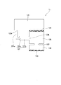
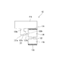
- FIG. It is a schematic diagram of the anti-vibration apparatus shown in FIG. It is a longitudinal cross-sectional view of the vibration isolator which concerns on 5th Embodiment of this invention. It is a schematic diagram of the anti-vibration apparatus shown in FIG. It is a longitudinal cross-sectional view of the vibration isolator which concerns on 6th Embodiment of this invention. It is a schematic diagram of the anti-vibration apparatus shown in FIG. It is a longitudinal cross-sectional view of the vibration isolator which concerns on 7th Embodiment of this invention. It is a schematic diagram of the anti-vibration apparatus shown in FIG. It is a longitudinal cross-sectional view of the vibration isolator which concerns on 8th Embodiment of this invention.
- FIG. 20 is a schematic view of the vibration control device shown in FIG. It is a longitudinal cross-sectional view of the vibration isolator which concerns on 11th Embodiment of this invention. It is a schematic diagram of the anti-vibration apparatus shown in FIG.
- FIG. 24 is a schematic view of the vibration control device shown in FIG. It is a longitudinal cross-sectional view of the vibration isolator which concerns on 13th Embodiment of this invention. It is a schematic diagram of the anti-vibration apparatus shown in FIG.
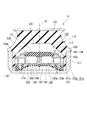
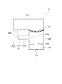
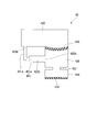
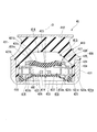
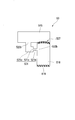
- the vibration damping device 11 has a cylindrical first mounting member 111 connected to one of the vibration generating portion and the vibration receiving portion, and a second mounting member 112 connected to the other. , An elastic body 113 connecting the first mounting member 111 and the second mounting member 112, a main liquid chamber 115 having the liquid body 114 in the first mounting member 111 as the elastic body 113 as a part of the partition, And a partition member 117 for partitioning the secondary fluid chamber 116.
- the partitioning member 117 partitions the liquid chamber 114 in the axial direction along the central axis O of the first mounting member 111.
- the first mounting member 111 is connected to a vehicle body as a vibration receiving portion
- the second mounting member 112 is connected to an engine as a vibration generating portion . Thereby, transmission of engine vibration to the vehicle body is suppressed.
- the main liquid chamber 115 side along the axial direction with respect to the partition member 117 is referred to as the upper side
- the sub liquid chamber 116 side is referred to as the lower side.
- a direction orthogonal to the central axis O is referred to as a radial direction
- a direction circling around the central axis O is referred to as a circumferential direction.
- the first attachment member 111 is formed in a bottomed cylindrical shape.
- the bottom of the first mounting member 111 is formed in an annular shape, and is disposed coaxially with the central axis O.
- the inner peripheral surface of the lower part of the first mounting member 111 is covered with a covering rubber formed integrally with the elastic body 113.
- the second mounting member 112 is formed in a flat plate shape whose front and back surfaces are orthogonal to the central axis O.
- the second mounting member 112 is formed, for example, in a disk shape, and is disposed coaxially with the central axis O.
- the second mounting member 112 is disposed above the first mounting member 111.
- the outer diameter of the second mounting member 112 is equal to the inner diameter of the first mounting member 111.
- the elastic body 113 connects the inner peripheral surface of the upper portion of the first mounting member 111 and the lower surface of the second mounting member 112.
- the upper end opening of the first mounting member 111 is sealed by the elastic body 113.
- the elastic body 113 is bonded by vulcanization to the first mounting member 111 and the second mounting member 112.
- the elastic body 113 is formed in a top cylindrical shape and is disposed coaxially with the central axis O.
- the top wall portion of the elastic body 113 is connected to the second mounting member 112, and the lower end portion of the peripheral wall portion is connected to the first mounting member 111.
- the peripheral wall portion of the elastic body 113 extends radially outward gradually from the upper side to the lower side.
- a diaphragm ring 118 is fluid-tightly fitted in the lower end portion of the first mounting member 111 via the covering rubber.
- the diaphragm ring 118 is formed in a double cylindrical shape and disposed coaxially with the central axis O.
- the outer peripheral portion of the diaphragm 119 which is elastically deformable by rubber or the like is bonded to the diaphragm ring 118 by vulcanization.
- the outer cylinder portion is fitted in the first mounting member 111, and the inner cylinder portion is embedded in the diaphragm 119.
- the diaphragm 119 is bonded by vulcanization to the inner peripheral surface of the outer cylinder portion of the diaphragm ring 118.
- the diaphragm 119 expands and contracts as the liquid flows into and out of the auxiliary liquid chamber 116.
- a liquid chamber 114 in which the liquid is enclosed is defined in the first mounting member 111 by the diaphragm 119 and the elastic body 113.
- As the liquid sealed in the liquid chamber 114 water, ethylene glycol, or the like can be used, for example.
- the partition member 117 is formed in a disk shape whose front and back surfaces are orthogonal to the central axis O, and is fitted in the first mounting member 111 via the covering rubber.
- the liquid chamber 114 in the first mounting member 111 is divided by the partition member 117 by the main liquid chamber 115 defined by the elastic body 113 and the partition member 117, and the secondary liquid defined by the diaphragm 119 and the partition member 117. It is divided into the chamber 116.
- the partition member 117 closes the upper end opening of the cylindrical main body member 134 fitted in the first mounting member 111 via the covering rubber and the upper end of the main body member 134 and part of the partition of the main liquid chamber 115
- An intermediate liquid chamber 135 positioned on the opposite side of the main liquid chamber 115 with the membrane 131 as a part of the partition wall, with the membrane 131 forming the lower end member of the lower end opening of the body member 134 closed.
- the annular fixing member 138 for fixing the membrane 131 to the main body member 134, the first orifice passage 121 for communicating the main liquid chamber 115 and the intermediate liquid chamber 135, and the intermediate liquid chamber 135 and the auxiliary liquid chamber 116 are communicated.
- a second orifice passage 122 a liquid chamber located on the opposite side of the main liquid chamber with the membrane interposed therebetween and having the membrane in a part of the partition is called an opposite liquid chamber.
- the opposite liquid chamber in the present embodiment and the second embodiment described later is an intermediate liquid chamber 135.
- the membrane 131 is formed in a disc shape by an elastic material such as rubber.
- the membrane 131 is disposed coaxially with the central axis O.
- the volume of the membrane 131 is smaller than the volume of the elastic body 113.
- the main body member 134 includes a main body ring 123 fitted in the first mounting member 111, an outer flange portion 124 projecting radially inward from an upper end portion of the main body ring 123, and a lower end portion of the outer flange portion 24. And an inner flange portion 125 projecting radially inward.
- the body ring 123, the outer flange portion 124, and the inner flange portion 125 are disposed coaxially with the central axis O.
- the lower surfaces of the outer flange portion 124 and the inner flange portion 125 are flush with each other.
- the membrane 131 is fitted in the outer flange portion 124.
- the outer peripheral edge of the lower surface of the membrane 131 is supported by the inner flange portion 125.
- the membrane 131 projects above the upper surface of the outer flange portion 124.
- the outer peripheral edge of the upper surface of the membrane 131 is supported by a fixing member 138, and the outer peripheral edge of the membrane 131 is axially sandwiched and fixed by the fixing member 138 and the inner flange portion 125. Therefore, the membrane 131 is supported so as to be elastically deformable in the axial direction with the outer peripheral edge portion as a fixed end.
- the fixing member 138 is disposed coaxially with the central axis O, and the outer peripheral portion of the fixing member 138 is disposed on the upper surface of the outer flange portion 124, and the inner peripheral portion supports the upper surface of the membrane 131.
- first orifice groove 123a On the outer peripheral surface of the main body ring 123 of the main body member 134, there is formed a first orifice groove 123a which is opened radially outward and extends in the circumferential direction. The radially outer opening of the first orifice groove 123a is closed by the covering rubber.
- a first communication hole 123 b communicating the main fluid chamber 115 and the first orifice groove 123 a is formed on the top surface of the main body ring 123.
- the first communication hole 123 b axially communicates the main liquid chamber 115 with the first orifice groove 123 a.
- the first orifice groove 123a extends circumferentially around the central axis O from the first communication hole 123b toward one side in the circumferential direction over an angle range of more than 180 °.
- the lower member 133 is formed in a bottomed cylindrical shape, and is disposed coaxially with the central axis O.
- the lower member 133 is fluid-tightly fitted within the body ring 123 of the body member 134.
- the bottom wall portion of the lower side member 133 forms a partition wall which axially divides the sub liquid chamber 116 and the intermediate liquid chamber 135.
- the upper end opening edge of the peripheral wall portion of the lower member 133 is in contact with the lower surfaces of the outer flange portion 124 and the inner flange portion 125 of the main body member 134 integrally.
- the upper surface of the bottom wall of the lower member 133 is spaced downward from the lower surface of the membrane 131.
- the above-described intermediate liquid chamber 135 is defined by the upper surface of the bottom wall portion of the lower member 133 and the inner peripheral surface of the peripheral wall portion, and the lower surface of the membrane 131.
- An intermediate liquid chamber 135 and a main liquid chamber 115 are axially separated by a membrane 131.
- the internal volume of the intermediate liquid chamber 135 is smaller than the internal volume of the main liquid chamber 115.
- the outer peripheral surface of the peripheral wall portion of the lower member 133 is formed with a second orifice groove 133a which is opened outward in the radial direction and extends in the circumferential direction.
- the radially outer opening of the second orifice groove 133 a is closed by the inner circumferential surface of the main ring 123.
- a second communication hole 133 b communicating the second orifice groove 133 a with the intermediate liquid chamber 135 is formed on the inner peripheral surface of the peripheral wall portion of the lower member 133.
- the second communication hole 133 b communicates the second orifice groove 133 a and the intermediate liquid chamber 135 in the radial direction.
- the second orifice groove 133a extends circumferentially around the central axis O from the second communication hole 133b toward one side in the circumferential direction over an angle range of more than 180 °.
- One end of each of the second orifice groove 133a and the first orifice groove 123a in the circumferential direction is disposed at the same circumferential position.
- An auxiliary liquid chamber 116 is defined by the lower surface of the bottom wall portion of the lower member 133 and the diaphragm 119.
- the bottom wall portion of the lower member 133 is formed with a second orifice passage 122 communicating the sub fluid chamber 116 with the intermediate fluid chamber 135.
- the second orifice passage 122 axially communicates the sub fluid chamber 16 and the intermediate fluid chamber 135.
- An opening on the side of the intermediate liquid chamber 135 in the second orifice passage 122 faces the membrane 131.
- the second orifice passage 122 is a through hole formed in the bottom wall of the lower member 133, and a plurality of second orifice passages 122 are formed in the bottom wall of the lower member 133. All of these second orifice passages 122 axially face the membrane 131.
- the diaphragm ring 118 described above is disposed on an outer peripheral edge portion of the lower surface of the bottom wall portion of the lower member 133 which is located radially outward of the plurality of second orifice passages 122.
- the diaphragm ring 118 is integrally formed with the lower member 133.
- the portion of the diaphragm ring 118 located radially outward of the inner cylinder portion is located radially outward of the lower member 133, and on the upper surface of the connection portion between the outer cylinder portion and the inner cylinder portion, the body ring
- the lower surface of 123 is in fluid tight contact.
- each second orifice passage 122 The flow passage cross-sectional area and the flow passage length of each second orifice passage 122 are respectively smaller than the flow passage cross-sectional area and the flow passage length of the first orifice passage 121 described later.
- the second orifice passage 122 has a flow passage length smaller than the inner diameter.
- the flow passage length of the second orifice passage 122 may be equal to or larger than the inner diameter.
- the flow resistance of the liquid in each second orifice passage 122 is smaller than the flow resistance of the liquid in the first orifice passage 121.
- connection hole 121c for communicating the first orifice groove 123a and the second orifice groove 133a is formed.
- the connection hole 121 c communicates the first orifice groove 123 a and the second orifice groove 133 a in the radial direction.
- the first orifice passage 121 communicating the main fluid chamber 115 with the intermediate fluid chamber 135 has a first orifice groove 123a whose outer opening in the radial direction is closed by the covering rubber and an outer opening in the radial direction.
- the second orifice groove 133a closed by the inner circumferential surface of the main body ring 123 and the connection hole 121c.
- a portion located on the main liquid chamber 115 side and defined by the first orifice groove 123a is referred to as a main liquid chamber side passage 121a, and is located on the intermediate liquid chamber 135 side.
- the portion defined by the two orifice groove 133a is referred to as an intermediate liquid chamber side passage 121b.
- the opposite liquid chamber side passage a portion located on the opposite side of the main liquid chamber across the membrane and having the membrane as a part of the partition on the liquid chamber (opposite liquid chamber) side is called the opposite liquid chamber side passage.
- the opposite liquid chamber side passage in the present embodiment and the second embodiment described later is the intermediate liquid chamber side passage 121 b.
- connection hole 121c connects the one end of the first orifice groove 123a in the circumferential direction and the one end of the second orifice groove 133a in the circumferential direction.
- the liquid flows from any one of the main liquid chamber side passage 121a and the middle liquid chamber side passage 121b to the other through the connection hole 121c and flows in the other through the other.
- the flow direction of the liquid flowing in the other direction are opposite in the circumferential direction.
- a restraining member 126 for restraining the deformation deformation of the membrane 131 toward the intermediate liquid chamber 135 is disposed.
- the restraining member 126 is disposed on the partition member 117.
- the restraining member 126 is formed in a columnar shape standing upward from the bottom wall of the lower member 133.
- the lower surface of the membrane 131 is in contact with or in proximity to the upper end surface of the restraining member 126.
- the membrane 131 is in contact with the upper end surface of the restraining member 126 in a state where the pressing force directed upward from the restraining member 126 is not applied.
- the membrane 131 is smoothly bulged toward the main liquid chamber 115 side with a small force when the rebound load is input. It becomes possible to make it possible to prevent the rise of the damping force.
- the restraining member 126 is in contact with or in proximity to the radial center of the membrane 131.
- the restraining member 126 may be formed, for example, in a cylindrical shape, or may be in contact with a portion of the membrane 131 away from the central portion in the radial direction, or the like. It may be formed in a plate shape which contacts etc., and may be suitably changed not only in the above-mentioned embodiment.
- the restraining member 126 may be appropriately changed, for example, disposed on the first mounting member 111.
- the restraining member 126 may be integrally formed of the same material as the membrane 131. The restraining member 126 may abut on the membrane 131 in a state where a pressing force directed upward is applied.
- the flow resistance of the liquid in the main liquid chamber side channel 121a is higher than the flow resistance of the liquid in the intermediate liquid chamber side channel 121b.
- the flow passage cross-sectional area of the main liquid chamber side passage 121a is smaller than the flow passage cross-sectional area of the intermediate liquid chamber side passage 121b.
- the opening area of the connection hole 121c is smaller than the flow passage cross-sectional area of the main liquid chamber side passage 121a.
- the flow passage length of the connection hole 121c is shorter than the flow passage length of the main liquid chamber side passage 121a and the intermediate liquid chamber side passage 121b.
- the axial length of the intermediate liquid chamber side passage 121b is the radial length of the intermediate liquid chamber side passage 121b and the axial direction of the main liquid chamber side passage 121a. It is equal to the length of the In a longitudinal sectional view of the first orifice passage 121, the radial length of the main liquid chamber side passage 121a is shorter than the axial length of the main liquid chamber side passage 121a.
- the flow resistances of the main liquid chamber side passage 121a and the first communication holes 123b may be equal to each other or may be different from each other.
- the flow resistance of the main liquid chamber side passage 121a is higher than the flow resistance of the first communication hole 123b
- the flow resistance of the liquid when passing through the first communication hole 123b and entering the main liquid chamber side passage 121a is The increase causes a high damping force to be generated at the time of the input of the bound load which causes the liquid to flow from the main liquid chamber 115 toward the sub liquid chamber 116 side.
- the flow resistances of the connection hole 121c and the main liquid chamber side passage 121a may be equal to each other or may be different from each other. For example, when the flow resistance of the connection hole 121c is higher than the flow resistance of the main liquid chamber side passage 121a, the flow resistance of the liquid when it passes through the main liquid chamber side passage 121a and enters the connection hole 121c increases, and bounces A high damping force is generated when the load is input.
- the flow resistances of the intermediate liquid chamber side passage 121b and the connection hole 121c may be equal to each other or may be different from each other. For example, if the flow resistance of the intermediate liquid chamber side channel 121b is higher than the flow resistance of the connection hole 121c, the flow resistance of the liquid when it passes through the connection hole 121c and enters the intermediate liquid chamber side channel 121b increases, and bounces A high damping force is generated when the load is input.
- the flow resistances of the second communication holes 133 b and the intermediate liquid chamber side passages 121 b may be equal to each other or may be different from each other. For example, when the flow resistance of the second communication hole 133b is higher than the flow resistance of the intermediate liquid chamber side passage 121b, the flow resistance of the liquid when passing through the intermediate liquid chamber side passage 121b and entering the second communication hole 133b is It increases, and high damping force is generated when the bound load is input.
- the opening direction in which the first orifice passage 121 opens toward the intermediate liquid chamber 135, that is, the opening direction of the second communication hole 133b toward the intermediate liquid chamber 135 is the second orifice passage 122 is the intermediate liquid. It intersects the opening direction that opens toward the chamber 135.
- the second communication hole 133 b radially opens toward the intermediate liquid chamber 135, and the second orifice passage 122 axially opens toward the intermediate liquid chamber 135. That is, the opening direction of the second communication hole 133 b toward the intermediate liquid chamber 135 is orthogonal to the opening direction in which the second orifice passage 122 opens toward the intermediate liquid chamber 135.
- the cross-sectional area of the intermediate liquid chamber 135 along the direction orthogonal to the opening direction in which the second orifice passage 122 opens toward the intermediate liquid chamber 135 is the flow passage cross-sectional area of the second orifice passage 122
- the flow passage cross-sectional area of the intermediate liquid chamber side passage 121 b of the first orifice passage 121 and the flow passage cross-sectional area of the main liquid chamber side passage 121 a of the first orifice passage 121 are larger.
- the main liquid chamber side channel 121a and the intermediate liquid chamber side channel 121b are channels whose channel length is longer than the channel diameter.
- the flow passage cross-sectional shape of the first orifice passage 121 is rectangular, and in this case, the flow passage diameter is a flow passage cross-sectional shape in a circular shape having the same flow passage cross-sectional area It can be represented by the diameter of this circular shape when replaced.
- the suppression member 126 for suppressing the bulging deformation of the membrane 131 toward the intermediate liquid chamber 135 since the suppression member 126 for suppressing the bulging deformation of the membrane 131 toward the intermediate liquid chamber 135 is provided, the liquid from the main liquid chamber 115 A bound load to be circulated toward the secondary fluid chamber 116 is input, and when positive pressure is applied to the primary fluid chamber 115, the membrane 131 is restrained from being bulged and deformed toward the intermediate fluid chamber 135. The positive pressure of the main fluid chamber 115 is not relieved, and a high damping force can be generated.
- the restraining member 126 does not inhibit the deformation of the membrane 131, and the membrane An increase in damping force can be suppressed by causing the 131 to bulge and deform smoothly toward the main liquid chamber 115 side.
- the intermediate liquid chamber (the bulging deformation of the membrane 131 toward the main liquid chamber 115 and the bulging deformation of the membrane 131 toward the intermediate liquid chamber (opposite liquid chamber) It is a damping force difference expanding portion that suppresses the swelling deformation toward the opposite fluid chamber) 135 side and enlarges the difference between the damping force generated at the time of inputting the bound load and the damping force generated at the time of inputting the rebound load.
- the partition member 117 is provided with the intermediate liquid chamber 135 having the membrane 131 in a part of the partition wall, the liquid of the main liquid chamber 115 passes through the first orifice passage 121 when the bound load is input.
- the membrane 131 elastically deforms so as to expand toward the main liquid chamber 115 side when it flows into the fluid chamber. Therefore, while the liquid in the main fluid chamber 115 flows into the second orifice passage 122, the flow velocity thereof is reduced, and a high damping force can be generated when a bound load is input.
- the damping force which arises at the time of the input of a bound load can be raised rather than the damping force which arises at the time of the input of a rebound load.
- the flow resistance of the liquid in the main liquid chamber side channel 121a is higher than the flow resistance of the liquid in the intermediate liquid chamber side channel 121b.
- the resistance is greater than when directly flowing into the intermediate fluid chamber side passage 121b. Is granted. Thereby, high damping force can be generated at the time of input of a bound load.
- the flow resistances of the main liquid chamber side passage 121a and the intermediate liquid chamber side passage 121b are different from each other. Also, since both of them constitute one orifice passage in series with each other, it is possible to suppress the resistance that occurs when the liquid passes through the boundary portion, and the damping force generated when the rebound load is input is It can be suppressed. From the above, it is possible to reliably increase the damping force generated at the time of the input of the bound load more than the damping force generated at the time of the input of the rebound load, and the difference between these two damping forces is increased. It is possible to increase the ratio of damping force generated at the time of input of bound load to.
- the membrane 131 bulges and deforms toward the main fluid chamber 115 side, so that the negative pressure of the main fluid chamber 115 Can also suppress cavitation from occurring.
- a member that operates when each of these effects and effects, for example, the fluid pressure in the main fluid chamber 115 reaches a predetermined value is not employed, and the fluid flow in the main fluid chamber side passage 121a as described above. Since the resistance is higher than the flow resistance of the liquid in the middle liquid chamber side passage 121b, and the membrane 131 plays a part of the partitions of both the main liquid chamber 115 and the middle liquid chamber 135, the comparison is made. Even in the case of a vibration with a small amplitude, the above-mentioned effects can be stably and accurately achieved.
- the opening direction in which the first orifice passage 121 opens toward the intermediate liquid chamber 135 intersects with the opening direction in which the second orifice passage 122 opens toward the intermediate liquid chamber 135, It is possible to suppress the flow of the liquid from the side of the main liquid chamber 115 that has flowed in toward the second orifice passage 122, and the liquid can be diffused in the intermediate liquid chamber 135. This reliably reduces the flow velocity of the liquid in the main liquid chamber 115 until it flows into the second orifice passage 122.
- the cross-sectional area of the intermediate liquid chamber 135 is larger than the flow passage cross-sectional area of the second orifice passage 122, the resistance generated when the liquid in the intermediate liquid chamber 135 flows into the second orifice passage 122 is enhanced. It is possible to reliably increase the damping force that occurs when entering a bound load.
- the main liquid chamber side passage 121a of the first orifice passage 121 is a passage whose flow path length is longer than the flow passage diameter, resistance given to the liquid from the main liquid chamber 115 side flowing through this portion is It can be enhanced more reliably.
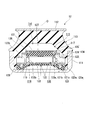
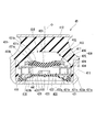
- FIGS. 3 and 4 a vibration proofing apparatus according to a second embodiment of the present invention will be described with reference to FIGS. 3 and 4.
- the same parts as the constituent elements in the first embodiment are denoted by the same reference numerals, and the description thereof is omitted, and only different points will be described.
- the diaphragm ring 128 is formed in a top cylindrical shape having an annular top wall and is disposed coaxially with the central axis O.
- the top wall portion of the diaphragm ring 128 is formed with a cylinder protruding downward and disposed coaxially with the central axis O.
- the outer peripheral portion of the diaphragm 119 is bonded by vulcanization to the inner surface of the diaphragm ring 128.
- the cylindrical body of the diaphragm ring 128 is embedded in the diaphragm 119.
- the upper surface of the top wall portion of the diaphragm ring 128 is in fluid-tight contact with the lower surface of the main body ring 123 of the partition member 117.
- the outer flange portion 124 of the partition member 117 protrudes upward from the inner peripheral edge portion of the upper surface of the main body ring 123.
- the inner flanges 124 and the inner peripheral surface of the main ring 123 are flush with each other.
- the upper end opening edge of the peripheral wall portion of the lower member 133 is in contact with the lower surface of the inner flange portion 125 of the main body member 134.
- a restraining member 127 for restraining bulging deformation of the membrane 131 toward the main liquid chamber 115 is disposed.
- the restraining member 127 is formed in a plate shape, and the outer peripheral edge portion thereof is disposed on the inner peripheral portion of the fixing member 138.
- a plurality of through holes extending in the axial direction are formed in the suppressing member 127 over the entire area.
- the upper surface of the membrane 131 is in contact with or in close proximity to the lower surface of the restraining member 127 over the entire area. In the illustrated example, the membrane 131 is in contact with the lower surface of the restraining member 127 in a state where a pressing force directed downward from the restraining member 127 is not applied.
- the restraining member 127 may be formed in, for example, a columnar or cylindrical shape that is in contact with or close to a part of the upper surface of the membrane 131, and may be changed as appropriate without being limited to the above embodiment.
- the restraining member 127 may be appropriately changed, for example, disposed on the first attachment member 111.
- the flow resistance of the liquid in the intermediate liquid chamber side passage 121b is higher than the flow resistance of the liquid in the main liquid chamber side passage 121a.
- the flow passage cross-sectional area of the intermediate liquid chamber side passage 121b is smaller than the flow passage cross-sectional area of the main liquid chamber side passage 121a.
- the opening area of the connection hole 121c is smaller than the flow passage cross-sectional area of the intermediate liquid chamber side passage 121b.
- the axial length of the intermediate liquid chamber side passage 121b is longer than the radial length of the intermediate liquid chamber side passage 121b, and the axis of the main liquid chamber side passage 121a. It is equal to the length of the direction.
- the radial length of the main liquid chamber side passage 121a is longer than the axial length of the main liquid chamber side passage 121a.
- the flow resistances of the intermediate liquid chamber side passage 121b and the second communication hole 133b may be equal to each other or may be different from each other.
- the flow resistance of the intermediate liquid chamber side passage 121b is higher than the flow resistance of the second communication hole 133b, the flow resistance of the liquid when passing through the second communication hole 133b and entering the intermediate liquid chamber side passage 121b is The increase causes a high damping force to be generated at the time of input of a rebound load that causes the liquid to flow from the sub fluid chamber 116 toward the main fluid chamber 115 side.
- the flow resistances of the connection hole 121c and the intermediate liquid chamber side passage 121b may be equal to each other or may be different from each other. For example, when the flow resistance of the connection hole 121c is higher than the flow resistance of the intermediate liquid chamber side passage 121b, the flow resistance of the liquid when passing through the intermediate liquid chamber side passage 121b and entering the connection hole 121c increases, and rebound occurs. A high damping force is generated when the load is input.
- the flow resistances of the main liquid chamber side passage 121a and the connection hole 121c may be equal to each other or may be different from each other. For example, when the flow resistance of the main liquid chamber side passage 121a is higher than the flow resistance of the connection hole 121c, the flow resistance of the liquid when it passes through the connection hole 121c and enters the main liquid chamber side passage 121a increases, and rebound occurs. A high damping force is generated when the load is input.
- the flow resistances of the first communication holes 123b and the main liquid chamber side passage 121a may be equal to each other or may be different from each other. For example, when the flow resistance of the first communication hole 123b is higher than the flow resistance of the main liquid chamber side passage 121a, the flow resistance of the liquid when passing through the main liquid chamber side passage 121a and entering the first communication hole 123b is It increases, and high damping force occurs when rebound load is input.
- the suppressing member 127 for suppressing the bulging deformation of the membrane 131 toward the main liquid chamber 115 side since the suppressing member 127 for suppressing the bulging deformation of the membrane 131 toward the main liquid chamber 115 side is provided, a rebound load is input.
- a negative pressure acts on the liquid chamber 115, the membrane 131 is restrained from bulging and deforming toward the main liquid chamber 115 side, so the negative pressure of the main liquid chamber 115 is not relieved, and a high damping force can be obtained. Can be generated.
- the restraining member 127 does not suppress the deformation of the membrane 131, and the membrane 131 smoothly bulges and deforms toward the intermediate liquid chamber 135.
- the restraining member 127 of the present embodiment is the main liquid chamber 115 side among the bulging deformation of the membrane toward the main liquid chamber 115 and the bulging deformation of the membrane toward the intermediate liquid chamber (opposite liquid chamber) 135.
- This is a damping force difference enlarging unit that suppresses the bulging deformation toward the side and enlarges the difference between the damping force generated at the time of input of the bound load and the damping force generated at the time of input of the rebound load.
- the partition member 117 is provided with the intermediate liquid chamber 135, when the liquid in the auxiliary liquid chamber 116 flows into the intermediate liquid chamber 135 when the rebound load is input, the wall surface of the auxiliary liquid chamber 116 is formed. Among them, the second orifice passage 122 collides with the opened surface, and the flow velocity is reduced while the liquid in the sub fluid chamber 116 flows into the first orifice passage 121, and the rebound load is input. Sometimes high damping forces can be generated. As mentioned above, the damping force which arises at the time of the input of a rebound load can be raised rather than the damping force which arises at the time of the input of a bounce load.
- the flow resistance of the liquid in the intermediate liquid chamber side passage 121b is higher than the flow resistance of the liquid in the main liquid chamber side passage 121a.
- the flow resistances of the main liquid chamber side passage 121a and the intermediate liquid chamber side passage 121b are different from each other. Also, since both of them constitute one orifice passage in series with each other, it is possible to suppress the resistance that occurs when the liquid passes through the boundary portion, and the damping force generated when the bound load is input is It can be suppressed.
- a member that is activated when the hydraulic pressure in the main fluid chamber 115 reaches a predetermined value does not employ these functional effects, and the fluid flow in the intermediate fluid chamber side passage 121b as described above. Since the resistance is higher than the flow resistance of the liquid in the main liquid chamber side passage 121a, and the membrane 131 is provided by a part of the partition of both the main liquid chamber 115 and the intermediate liquid chamber 135, the comparison is made. Even in the case of a vibration with a small amplitude, the above-mentioned effects can be stably and accurately achieved.
- the cross-sectional area of the intermediate liquid chamber 135 is larger than the flow passage cross-sectional area of the intermediate liquid chamber side passage 121b of the first orifice passage 121, the liquid in the intermediate liquid chamber 135 is transferred to the intermediate liquid chamber side passage 121b. It is possible to reliably increase the resistance generated when flowing in, and it is possible to reliably increase the damping force generated when a rebound load is input.
- the middle liquid chamber side channel 121b of the first orifice channel 121 is a channel whose channel length is longer than the channel diameter, the resistance given to the liquid from the side of the sub liquid chamber 116 flowing through this portion is It can be enhanced more reliably.
- the vibration control devices 11 and 12 include the cylindrical first mounting member 111 connected to one of the vibration generating unit and the vibration receiving unit, and the other.
- the second mounting member 112 to be connected, the elastic body 113 connecting the first mounting member 111 and the second mounting member 112, the liquid chamber in the first mounting member 111, the elastic body 113 as a part of the partition wall
- the partition member 117 has a membrane 131 forming a part of a partition of the main liquid chamber 115, the main liquid chamber 115, and the membrane 131.
- the vibration damping devices 11 and 12 are provided with the damping force difference widening portion, either one of the swelling deformation of the membrane 131 toward the main liquid chamber 115 and the swelling deformation of the membrane 131 toward the opposite liquid chamber Can be suppressed, and the difference between the damping force generated at the input of the bound load and the damping force generated at the input of the rebound load can be increased.
- the partition member 117 further includes an intermediate liquid chamber 135 which is an opposite liquid chamber, and a second orifice passage 122 communicating the intermediate liquid chamber 135 and the auxiliary liquid chamber 116, and the damping force difference expanding portion
- the membrane 131 may be provided with restraining members 126 and 127 for restraining either one of the bulging deformation of the membrane 131 toward the intermediate liquid chamber 135 and the bulging deformation of the membrane 131 toward the main liquid chamber 115.
- the restraining member 126 suppresses the bulging deformation of the membrane 131 toward the intermediate liquid chamber 135, the vibration is distributed from the main liquid chamber 115 toward the sub liquid chamber 116 to the vibration damping device 11.
- the membrane 131 is prevented from expanding and deforming toward the intermediate fluid chamber 135, so that the positive pressure of the main fluid chamber 115 is reduced. It is not relieved and high damping force can be generated.
- the restraining member 126 does not inhibit the deformation of the membrane 131,
- the membrane 131 smoothly bulges and deforms toward the main fluid chamber, thereby suppressing an increase in damping force.
- the partition member 117 is provided with the intermediate liquid chamber 135 having the membrane 131 in a part of the partition wall, the liquid in the main liquid chamber flows to the intermediate liquid chamber 135 through the first orifice passage 121 when the bound load is input.
- the membrane 131 elastically deforms so as to expand toward the main liquid chamber 115 side.
- the restraining member 127 suppresses the bulging deformation toward the main fluid chamber 115 side of the membrane 131
- a rebound load is input to the vibration damping device 12 and a negative pressure acts on the main fluid chamber 115
- the membrane 131 is restrained from expanding and deforming toward the main fluid chamber 115, the negative pressure of the main fluid chamber 115 is not relieved, and a high damping force can be generated.
- the restraining member 127 does not suppress the deformation of the membrane 131, and the membrane 131 smoothly bulges and deforms toward the intermediate liquid chamber 135. The increase in damping force is suppressed.
- the partition member 117 is provided with the intermediate liquid chamber 135, when the liquid in the auxiliary liquid chamber 116 flows into the intermediate liquid chamber 135 when the rebound load is input, the wall surface of the auxiliary liquid chamber 116 is formed. Among them, the second orifice passage 122 collides with the opened surface, and the flow velocity is reduced while the liquid in the sub fluid chamber 116 flows into the first orifice passage 121, and the rebound load is input. Sometimes high damping forces can be generated. As mentioned above, the damping force which arises at the time of the input of a rebound load can be raised rather than the damping force which arises at the time of the input of a bounce load.
- the restraining member 126 suppresses the bulging deformation of the membrane 131 toward the intermediate liquid chamber 135 side, and the flow resistance of the liquid in the main liquid chamber side passage 121 a of the first orifice passage 121 is the opposite liquid. It may be higher than the flow resistance of the liquid in the intermediate liquid chamber side passage 121b positioned on the intermediate liquid chamber 135 side as the chamber side passage.
- the flow resistance of the liquid in a portion (hereinafter referred to as main liquid chamber side channel 121 a) of the first orifice passage 121 communicating the main liquid chamber 115 and the intermediate liquid chamber 135 is located on the main liquid chamber 115 side. Since the flow resistance of the liquid in the portion located on the side of the intermediate liquid chamber 135 (hereinafter referred to as the intermediate liquid chamber side passage 121b) is higher, the liquid in the main liquid chamber 115 is in the first orifice passage 121 when the bound load is input. When flowing into the main liquid chamber side passage 121a, a greater resistance is given as compared with the case of flowing directly into the intermediate liquid chamber side passage 121b.
- the restraining member 126 suppresses the bulging deformation of the membrane 131 toward the intermediate liquid chamber 135, as described above, high damping force can be generated at the time of input of the bound load. From the above, it is possible to reliably increase the damping force generated at the time of the input of the bound load more than the damping force generated at the time of the input of the rebound load, and the difference between these two damping forces is increased. It is possible to increase the ratio of damping force generated at the time of input of bound load to.
- the membrane 131 bulges and deforms toward the main fluid chamber 115 side, so that the negative pressure of the main fluid chamber 115 Can also suppress cavitation from occurring.
- a member that operates when each of these effects and effects, for example, the fluid pressure in the main fluid chamber 115 reaches a predetermined value is not employed, and the fluid flow in the main fluid chamber side passage 121a as described above.
- the membrane 131 is realized by the configuration of forming a part of both the main liquid chamber 115 and the middle liquid chamber 116, Even in the case of a vibration with a small amplitude, the above-mentioned effects can be stably and accurately achieved.
- the opening direction in which the first orifice passage 121 opens toward the intermediate fluid chamber 135 may intersect the opening direction in which the second orifice passage 122 opens toward the intermediate fluid chamber 135.
- the cross sectional area of the intermediate liquid chamber 135 along the direction orthogonal to the opening direction in which the second orifice passage 122 opens toward the intermediate liquid chamber 135 is larger than the flow passage cross sectional area of the second orifice passage 122. It is also good.
- the cross-sectional area of the intermediate liquid chamber 135 is larger than the flow passage cross-sectional area of the second orifice passage 122, the resistance generated when the liquid in the intermediate liquid chamber 135 flows into the second orifice passage 122 is enhanced. It is possible to reliably increase the damping force that occurs when entering a bound load.
- the main liquid chamber side passage 121a may be a passage whose flow path length is longer than the flow passage diameter.
- the main liquid chamber side passage 121a of the first orifice passage 121 is a passage whose flow path length is longer than the flow passage diameter, the resistance given to the liquid from the main liquid chamber side flowing through the passage 121a Can be further enhanced.
- the restraining member 127 suppresses the bulging deformation of the membrane 131 toward the main liquid chamber 115 side, and the intermediate liquid chamber side flow passage 121 b located on the intermediate liquid chamber 116 side of the first orifice passage 121.
- the flow resistance of the liquid in the above may be higher than the flow resistance of the liquid in the main liquid chamber side passage 121a.
- the flow resistances of the main liquid chamber side passage 121a and the intermediate liquid chamber side passage 121b are different from each other. Also, since both of them constitute one orifice passage in series with each other, it is possible to suppress the resistance that occurs when the liquid passes through the boundary portion, and the damping force generated when the bound load is input is It can be suppressed. Furthermore, since the restraining member 127 suppresses the bulging deformation of the membrane 131 toward the main liquid chamber 115, as described above, a high damping force can be generated when a rebound load is input.
- the resistance is higher than the flow resistance of the liquid in the main liquid chamber side passage 121a, and the membrane 131 is provided by a part of the partition of both the main liquid chamber 115 and the intermediate liquid chamber 135, the comparison is made. Even in the case of a vibration with a small amplitude, the above-mentioned effects can be stably and accurately achieved.
- the cross-sectional area of the intermediate liquid chamber 135 along the direction orthogonal to the opening direction in which the second orifice passage 122 opens toward the intermediate liquid chamber 135 is the same as that of the intermediate liquid chamber side passage 121 b in the first orifice passage 121. It may be larger than the channel cross sectional area.
- the liquid in the intermediate liquid chamber 135 is the intermediate chamber side passage of the first orifice passage 121. It is possible to reliably increase the resistance that occurs when flowing into 121b, and it is possible to reliably increase the damping force that occurs when a rebound load is input.
- the intermediate liquid chamber side passage 121b may be a passage whose flow passage length is longer than the flow passage diameter.
- the intermediate chamber side passage 121b of the first orifice passage 121 is a passage having a flow passage length longer than the flow passage diameter, the resistance applied to the liquid from the side of the auxiliary liquid chamber 116 flowing through the passage 121b Can be further enhanced.
- the first orifice passage 121 extends in the circumferential direction
- the second orifice passage 122 extends in the axial direction
- the present invention is not limited thereto.
- the compression type vibration damping device 11, 12 in which the positive pressure acts on the main liquid chamber 115 by the application of the supporting load has been described, but the main liquid chamber 115 is positioned on the lower side in the vertical direction.
- the sub fluid chamber 116 is positioned at the upper side in the vertical direction, and it is also applicable to a suspension type vibration damping device in which a negative pressure acts on the main fluid chamber 115 by the support load.
- the vibration control device 11 is not limited to the engine mount of a vehicle, and may be applied to other than the engine mount.
- the invention can also be applied to a mount of a generator mounted on a construction machine, or to a mount of a machine installed in a factory or the like.
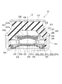
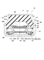
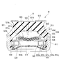
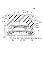
- the vibration damping device 21 has a cylindrical first attachment member 211 coupled to one of the vibration generating unit and the vibration receiving unit, and a second attachment member 212 coupled to the other.
- An elastic body 213 connecting the first mounting member 211 and the second mounting member 212, a main liquid chamber 215 having the liquid body 214 in the first mounting member 211 as a part of the partition wall, and And a partition member 217 for partitioning the secondary fluid chamber 216.
- the partitioning member 217 partitions the liquid chamber 214 in the axial direction along the central axis O of the first mounting member 211.
- the first mounting member 211 is connected to a vehicle body as a vibration receiving portion
- the second mounting member 212 is connected to an engine as a vibration generating portion .
- the first mounting member 211 may be connected to the vibration generating unit
- the second mounting member 212 may be connected to the vibration receiving unit.
- the main liquid chamber 15 side along the axial direction with respect to the partition member 217 is referred to as the upper side
- the sub liquid chamber 216 side is referred to as the lower side.
- a direction intersecting the central axis O is referred to as a radial direction
- a direction circling around the central axis O is referred to as a circumferential direction.
- the first attachment member 211 is formed in a bottomed cylindrical shape.
- the bottom of the first mounting member 211 is formed in an annular shape, and is disposed coaxially with the central axis O.
- the inner peripheral surface of the lower part of the first mounting member 211 is covered with a covering rubber formed integrally with the elastic body 213.
- the second mounting member 212 is formed in a flat plate shape whose front and back surfaces are orthogonal to the central axis O.
- the second attachment member 212 is formed, for example, in a disk shape, and is disposed coaxially with the central axis O.
- the second attachment member 212 is disposed above the first attachment member 211.
- the outer diameter of the second mounting member 212 is equal to the inner diameter of the first mounting member 211.
- the elastic body 213 connects the inner peripheral surface of the upper portion of the first mounting member 211 and the lower surface of the second mounting member 212.
- the upper end opening of the first mounting member 211 is sealed by the elastic body 213.
- the elastic body 213 is bonded by vulcanization to the first mounting member 211 and the second mounting member 212.
- the elastic body 213 is formed in a top cylindrical shape and is disposed coaxially with the central axis O.
- the top wall portion of the elastic body 213 is connected to the second mounting member 212, and the lower end portion of the peripheral wall portion is connected to the first mounting member 211.
- the peripheral wall portion of the elastic body 213 gradually extends outward in the radial direction as it goes downward from above.
- a diaphragm ring 218 is fluid-tightly fitted in the lower end portion of the first mounting member 211 via the covering rubber.
- the diaphragm ring 218 is formed in a double cylindrical shape and disposed coaxially with the central axis O.
- An outer peripheral portion of a diaphragm 219 which is elastically deformable by rubber or the like is bonded to the diaphragm ring 218 by vulcanization.
- the outer peripheral portion of the diaphragm 219 is vulcanized and bonded to the inner peripheral surface of the outer cylinder portion and the outer peripheral surface of the inner cylinder portion of the diaphragm ring 218.
- the diaphragm 219 expands and contracts as the liquid flows into and out of the sub fluid chamber 216.
- a liquid chamber 214 in which the liquid is enclosed is defined in the first attachment member 211 by the diaphragm 219 and the elastic body 213.
- As the liquid sealed in the liquid chamber 214 water, ethylene glycol, or the like can be used, for example.
- the partition member 217 is formed in a disk shape whose front and back surfaces are orthogonal to the central axis O, and is fitted in the first mounting member 211 via the covering rubber.
- the liquid chamber 214 in the first mounting member 211 is separated by the partition member 217, the main liquid chamber 215 is divided by the elastic member 213 and the partition member 217, and the auxiliary liquid is divided by the diaphragm 219 and the partition member 217.
- a chamber 216 is formed in a disk shape whose front and back surfaces are orthogonal to the central axis O, and is fitted in the first mounting member 211 via the covering rubber.
- the liquid chamber 214 in the first mounting member 211 is separated by the partition member 217, the main liquid chamber 215 is divided by the elastic member 213 and the partition member 217, and the auxiliary liquid is divided by the diaphragm 219 and the partition member 217.
- a chamber 216 is formed in a disk shape whose front and back surfaces are orthogonal to the central
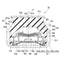
- the partition member 217 closes the upper end opening of the cylindrical main body member 234 and the main body member 234 fitted in the first attachment member 211 via the covering rubber, and part of the partition of the main liquid chamber 215
- An intermediate liquid chamber 235 positioned on the opposite side of the main liquid chamber 215 with the membrane 231 as a part of the partition wall, and the lower side member 233 closing the lower end opening of the main body member 234.
- an annular clamping member 239 for fixing the membrane 231 to the main body member 234, a first orifice passage 221 for communicating the main liquid chamber 215 and the intermediate liquid chamber 235, an intermediate liquid chamber 235 and an auxiliary liquid chamber 216.
- a second orifice passage 222 communicating with each other.
- a liquid chamber located on the opposite side of the main liquid chamber with the membrane interposed therebetween and having the membrane in a part of the partition is called an opposite liquid chamber.
- the opposite liquid chamber in the present embodiment and the fourth embodiment described later is an intermediate liquid chamber 235.
- the membrane 231 is formed in a disk shape by an elastic material such as rubber.
- the membrane 231 is disposed coaxially with the central axis O.
- the volume of the membrane 231 is smaller than the volume of the elastic body 213.
- the membrane 231 is formed thinner than the disc-shaped main body portion 231b and the main body portion 231b, and protrudes outward in the radial direction from the lower portion of the main body portion 231b, and extends continuously over the entire circumference. And. At the radially outer end portion of the outer peripheral edge portion 231a, locking projections that project toward both axial sides are formed.
- the main body member 234 is disposed coaxially with the central axis O.
- the outer peripheral surface of the main body member 234 is formed with a first orifice groove 223a which is opened outward in the radial direction and extends in the circumferential direction.
- the radially outer opening of the first orifice groove 223a is closed by the covering rubber.
- a first communication hole 223 b communicating the main liquid chamber 215 with the first orifice groove 223 a is formed on the upper surface of the main body member 234.
- the first communication hole 223 b axially connects the main liquid chamber 215 and the first orifice groove 223 a.
- the first orifice groove 223a extends circumferentially around the central axis O from the first communication hole 223b toward one side in the circumferential direction over an angle range of more than 180 °.
- the sandwiching member 239 sandwiches the outer peripheral edge portion 231 a of the membrane 231 from both the main liquid chamber 215 side and the intermediate liquid chamber 235 side.
- the sandwiching member 239 includes a first sandwiching portion 225 supporting the lower surface of the membrane 231 and a second sandwiching portion 238 supporting the upper surface of the membrane 231.
- the first clamping portion 225 and the second clamping portion 238 are each formed in an annular shape, and are arranged coaxially with the central axis O.
- the outer peripheral edge portion 231a of the membrane 231 is axially sandwiched and fixed by the first clamping portion 225 and the second clamping portion 238, so that the membrane 231 has the outer peripheral edge portion 231a as a fixed end in the axial direction. Is elastically supported.
- the first clamping portion 225 is connected to the main body member 234 via the outer flange portion 224.
- the outer flange portion 224 is integrally formed with the main body member 234 and protrudes radially inward from the upper end portion of the main body member 234.
- the outer flange portion 224 is disposed coaxially with the central axis O.
- the first clamping portion 225 is integrally formed with the outer flange portion 224 and protrudes radially inward from the outer flange portion 224.
- the lower surfaces of the first clamping portion 225 and the outer flange portion 224 are flush with each other.
- the upper surface of the first clamping portion 225 is located below the upper surface of the outer flange portion 224.
- a lower annular groove extending continuously over the entire circumference is formed.
- the outer peripheral portion of the second clamping portion 238 is disposed on the upper surface of the outer flange portion 224, and the inner peripheral portion supports the upper surface of the membrane 231.
- an upper annular groove extending continuously over the entire circumference is formed.
- the upper annular groove is axially opposed to the lower annular groove of the first clamping portion 225.
- the locking projections of the outer peripheral edge portion 231a of the membrane 231 are individually locked to the upper annular groove and the lower annular groove.
- a portion of the main body portion 231 b of the membrane 231 located above the outer peripheral edge portion 231 a is inserted inside the inner peripheral portion of the second clamping portion 238.
- the outer peripheral surface (hereinafter referred to as the outer peripheral surface 231c of the main body portion 231b of the membrane 231) of a portion of the main body portion 231b of the membrane 231 located above the outer peripheral edge portion 231a and the inner peripheral portion of the second clamping portion 238 A gap in the radial direction is provided between the inner circumferential surface and the inner circumferential surface.
- the inner circumferential surface of the inner circumferential portion of the second sandwiching portion 238 and the outer circumferential surface 231c of the main body portion 231b of the membrane 231 extend in the axial direction.
- the inner circumferential surface of the inner circumferential portion of the second sandwiching portion 238 and the outer circumferential surface 231 c of the main portion 231 b of the membrane 231 are substantially parallel.
- the inner circumferential surface of the inner circumferential portion of the second sandwiching portion 238 and the outer circumferential surface 231c of the main body portion 231b of the membrane 231 may be inclined to each other.
- the lower member 233 is formed in a bottomed cylindrical shape, and is disposed coaxially with the central axis O.
- the lower member 233 is fluid-tightly fitted in the main body member 234.
- the bottom wall portion of the lower side member 233 forms a partition wall which axially divides the sub liquid chamber 216 and the intermediate liquid chamber 235.
- the upper end opening edge of the peripheral wall portion of the lower member 233 is integrally in contact with the lower surfaces of the first clamping portion 225 and the outer flange portion 224.
- the upper surface of the bottom wall of the lower member 233 is spaced downward from the lower surface of the membrane 231.
- the above-described intermediate liquid chamber 235 is defined by the upper surface of the bottom wall portion of the lower member 233 and the inner peripheral surface of the peripheral wall portion and the lower surface of the membrane 231.
- An intermediate liquid chamber 235 and a main liquid chamber 215 are axially separated by a membrane 231.
- the internal volume of the intermediate liquid chamber 235 is smaller than the internal volume of the main liquid chamber 215.
- the outer peripheral surface of the peripheral wall portion of the lower member 233 is formed with a second orifice groove 233a which is opened outward in the radial direction and extends in the circumferential direction.
- the radially outer opening of the second orifice groove 233 a is closed by the inner circumferential surface of the main body member 234.
- a second communication hole 233 b communicating the second orifice groove 233 a with the intermediate liquid chamber 235 is formed on the inner peripheral surface of the peripheral wall portion of the lower member 233.
- the second communication hole 233 b communicates the second orifice groove 233 a and the intermediate liquid chamber 235 in the radial direction.
- the second orifice groove 233a extends circumferentially around the central axis O from the second communication hole 233b toward one side in the circumferential direction over an angle range of more than 180 °.
- One end of each of the second orifice groove 233a and the first orifice groove 223a in the circumferential direction is disposed at the same circumferential position.
- a sub fluid chamber 216 is defined by the lower surface of the bottom wall of the lower member 233 and the diaphragm 219.
- the bottom wall portion of the lower member 233 is formed with a second orifice passage 222 communicating the sub fluid chamber 216 with the intermediate fluid chamber 235.
- the second orifice passage 222 axially communicates the sub fluid chamber 216 and the intermediate fluid chamber 235.
- An opening on the side of the intermediate liquid chamber 235 in the second orifice passage 222 faces the membrane 31.
- the second orifice passage 222 is a through hole formed in the bottom wall portion of the lower member 233, and a plurality of second orifice passages 222 are formed in the bottom wall portion of the lower member 233. At least a part of the second orifice passages 222 axially faces the membrane 31.
- a regulation protrusion 226 is disposed which regulates an excessively large deformation of the membrane 231 toward the intermediate liquid chamber 235 side.
- the restriction protrusion 226 is integrally formed with the lower member 233.
- the restriction protrusion 226 is formed in a tubular shape, and is disposed coaxially with the central axis O.
- the restriction protrusion 226 may be formed solid, and may not be disposed coaxially with the central axis O.
- the diaphragm ring 218 described above is disposed on an outer peripheral edge portion located radially outward of the plurality of second orifice passages 222 on the lower surface of the bottom wall portion of the lower member 233.
- the diaphragm ring 218 is integrally formed with the lower member 233.
- the portion of the diaphragm ring 218 located radially outward of the inner cylinder portion is located radially outward of the lower member 233, and on the upper surface of the connection portion between the outer cylinder portion and the inner cylinder portion, the main body member
- the lower surface of 234 is in fluid tight contact.
- each second orifice passage 222 are respectively smaller than the flow passage cross-sectional area and flow passage length of the first orifice passage 221 described later.
- the second orifice passage 222 has a flow passage length smaller than the inner diameter.
- the flow passage length of the second orifice passage 222 may be equal to or larger than the inner diameter.
- the flow resistance of the liquid in each second orifice passage 222 is smaller than the flow resistance of the liquid in the first orifice passage 221.
- connection hole 221c for communicating the first orifice groove 223a with the second orifice groove 233a is formed.
- the connection hole 221 c communicates the first orifice groove 223 a and the second orifice groove 233 a in the radial direction.
- the first orifice passage 221 for communicating the main fluid chamber 215 with the intermediate fluid chamber 235 has a first orifice groove 223a whose outer opening in the radial direction is closed by the covering rubber, and an outer opening in the radial direction. It is comprised by the 2nd orifice 2 groove
- a portion located on the main fluid chamber 215 side and defined by the first orifice groove 223a is referred to as a main fluid chamber side passage 221a, and located on the intermediate fluid chamber 235 side.
- a portion defined by the two orifice groove 233a is referred to as an intermediate liquid chamber side passage 221b.
- the opposite liquid chamber side passage a portion located on the opposite side of the main liquid chamber across the membrane and having the membrane as a part of the partition on the liquid chamber (opposite liquid chamber) side is called the opposite liquid chamber side passage.
- the opposite liquid chamber side passage of the present embodiment and the fourth embodiment to be described later is the intermediate liquid chamber side passage 221 b.
- connection hole 221 c connects one end of the first orifice groove 223 a in the circumferential direction to the end of the second orifice groove 233 a in the circumferential direction.
- the liquid flows from any one of the main liquid chamber side passage 221a and the middle liquid chamber side passage 221b to the other through the connection hole 221c and flows in the other through the other.
- the flow direction of the liquid flowing in the other direction are opposite in the circumferential direction.
- the flow resistance of the liquid in the intermediate liquid chamber side channel 221b is lower than the flow resistance of the liquid in the main liquid chamber side channel 221a.
- the flow passage cross-sectional area of the main liquid chamber side passage 221a is smaller than the flow passage cross-sectional area of the intermediate liquid chamber side passage 221b.
- the opening area of the connection hole 221c is smaller than the flow passage cross-sectional area of the main liquid chamber side passage 221a.
- the flow passage length of the connection hole 221c is shorter than the flow passage length of the main liquid chamber side passage 221a and the intermediate liquid chamber side passage 221b.
- the flow resistances of the main liquid chamber side passage 221a and the first communication hole 223b may be equal to each other or may be different from each other.
- the flow resistance of the main liquid chamber side passage 221a is higher than the flow resistance of the first communication hole 223b, the flow resistance of the liquid when passing through the first communication hole 223b and entering the main liquid chamber side passage 221a is As a result, a high damping force is generated at the time of the input of the bound load which causes the liquid to flow from the main fluid chamber 215 toward the sub fluid chamber 216 side.
- the flow resistances of the connection hole 221c and the main liquid chamber side passage 221a may be equal to each other or may be different from each other. For example, when the flow resistance of the connection hole 221c is higher than the flow resistance of the main liquid chamber side passage 221a, the flow resistance of the liquid when it passes through the main liquid chamber side passage 221a and enters the connection hole 221c increases, and bounces A high damping force is generated when the load is input.
- the flow resistances of the intermediate liquid chamber side passage 221b and the connection hole 221c may be equal to each other or may be different from each other. For example, when the flow resistance of the intermediate liquid chamber side passage 221b is higher than the flow resistance of the connection hole 221c, the flow resistance of the liquid when it passes through the connection hole 221c and enters the intermediate liquid chamber side passage 221b increases, causing bounding A high damping force is generated when the load is input.
- the flow resistances of the second communication holes 233b and the intermediate liquid chamber side passage 221b may be equal to each other or may be different from each other. For example, when the flow resistance of the second communication hole 233b is higher than the flow resistance of the intermediate liquid chamber side passage 221b, the flow resistance of the liquid when passing through the intermediate liquid chamber side passage 221b and entering the second communication hole 233b is It increases, and high damping force is generated when the bound load is input.
- the opening direction in which the first orifice passage 221 opens toward the intermediate liquid chamber 235 that is, the opening direction of the second communication hole 233b toward the intermediate liquid chamber 235 is the second orifice passage 222 is the intermediate liquid. It intersects the opening direction that opens toward the chamber 235.
- the second communication hole 233 b radially opens toward the intermediate liquid chamber 235, and the second orifice passage 222 axially opens toward the intermediate liquid chamber 235. That is, the opening direction of the second communication hole 233 b toward the intermediate liquid chamber 235 is orthogonal to the opening direction of the second orifice passage 222 opening toward the intermediate liquid chamber 235.
- the cross-sectional area of the intermediate liquid chamber 235 along the direction orthogonal to the opening direction in which the second orifice passage 222 opens toward the intermediate liquid chamber 235 is the flow passage cross-sectional area of the second orifice passage 222
- the flow passage cross-sectional area of the intermediate liquid chamber side passage 221 b of the first orifice passage 221 and the flow passage cross-sectional area of the main liquid chamber side passage 221 a of the first orifice passage 221 are larger.
- the main liquid chamber side channel 221 a and the intermediate liquid chamber side channel 221 b are channels whose channel length is longer than the channel diameter.
- the flow passage cross-sectional shape of the first orifice passage 221 is rectangular, and in this case, the flow passage diameter is a flow passage cross-sectional shape in a circular shape having the same flow passage cross-sectional area It can be represented by the diameter of this circular shape when replaced.
- the intermediate liquid chamber 235 is an intermediate liquid chamber having a low flow resistance of the liquid among the main liquid chamber side passage 221a and the intermediate liquid chamber side passage 221b in the flow direction of the liquid in the first orifice passage 221. It is located on the side passage 221 b side. Then, in the present embodiment, when the same pressing force is applied to the membrane 31, a deflection is made such that the bulging deformation toward the main liquid chamber 215 is made larger than the bulging deformation toward the intermediate liquid chamber 235.
- the bulging part 223 is formed.
- the uneven bulging portion 223 is curved so as to protrude toward the intermediate liquid chamber 235 side.
- the unevenly bulged portion 223 is integrally formed over the entire region of the main body portion 231 b located radially inward of the outer peripheral edge portion 231 a sandwiched in the axial direction by the clamping member 239 in the membrane 231.
- the unevenly bulged portion 223 is not limited to the above-described curved shape, and may be changed as appropriate, for example, by making the sizes of the grooves formed on the upper and lower surfaces of the membrane 231 different.
- the first clamping portion 225 supporting the membrane 231 from the side of the intermediate liquid chamber 235 is located radially inward of the second clamping portion 238 supporting the membrane 231 from the side of the main liquid chamber 215. Protruding long.
- a portion located radially inward of the second clamping portion 238 supports the outer peripheral portion of the lower surface of the main body portion 231b of the membrane 231.
- the upper surface, to which the membrane 231 abuts is inclined downward so as to gradually separate from the main liquid chamber 215 as it goes inward in the radial direction.
- the upper surface of the inner peripheral edge portion of the first sandwiching portion 225 is formed in a curved surface shape protruding toward the main liquid chamber 215 side.
- the upper surface of the inner peripheral edge portion of the first clamping portion 225 may be a flat surface extending in the direction orthogonal to the central axis O.
- the lower surface of the membrane 231 is in contact with the upper surface of the inner peripheral edge portion of the first clamping portion 225.
- the unevenly bulged portion 223 of the membrane 231 protrudes to the inside of the first clamping portion 225.
- the axial positions of the lower end portion of the lower surface of the unevenly bulged portion 223 and the lower surface of the first clamping portion 225 are equal to each other.
- the lower surface of the membrane 231 is not in contact with the inner circumferential surface of the first clamping portion 225.
- the membrane 231 is in contact with the entire upper surface of the first clamping portion 225 and the lower surface of the inner peripheral portion of the second clamping portion 238.
- the lower surface of the membrane 231 may be separated upward from the upper surface of the inner peripheral edge portion of the first clamping portion 225.
- the partially bulging portion 223 of the membrane 231 may be positioned above the inner peripheral surface of the first clamping portion 225.
- the lower surface of the membrane 231 may be in contact with the inner circumferential surface of the first clamping portion 225.
- the vibration control device 21 since the uneven bulging portion 223 is formed on the membrane 231, the bulging deformation of the membrane 231 when the same pressing force is applied The amount of bulging deformation toward the main liquid chamber 215 is larger than the amount of bulging deformation toward the intermediate liquid chamber 235. Therefore, when the rebound load is input to the vibration damping device 21, the membrane 231 is greatly expanded and deformed toward the main liquid chamber 215 by the unevenly expanding portion 223 to suppress the generated damping force to a low level. it can.
- the unevenly bulging portion 223 of the present embodiment is an intermediate liquid chamber among the bulging deformation of the membrane toward the main liquid chamber 215 and the bulging deformation of the intermediate liquid chamber (opposite liquid chamber) 235 side.
- a damping force difference expanding portion that suppresses the swelling deformation toward the 235 side and enlarges the difference between the damping force generated at the time of input of the bound load and the damping force generated at the time of input of the rebound load.
- the flow resistance of the liquid in the intermediate liquid chamber side passage 221b is lower than the flow resistance of the liquid in the main liquid chamber side passage 221a, the liquid in the main liquid chamber 215 flows into the main liquid chamber side passage 221a when the bound load is input.
- a greater resistance is given as compared with the case where the fluid flows directly into the intermediate fluid chamber side passage 221b. Thereby, high damping force can be generated at the time of input of a bound load.
- the flow resistances of the main liquid chamber side passage 221a and the intermediate liquid chamber side passage 221b are different from each other. Also, since both of them constitute one orifice passage in series with each other, it is possible to suppress the resistance that occurs when the liquid passes through the boundary portion, and the damping force generated when the rebound load is input is It can be kept low. From the above, it is possible to reliably increase the damping force generated at the time of the input of the bound load more than the damping force generated at the time of the input of the rebound load, and the difference between these two damping forces is increased. It is possible to increase the ratio of damping force generated at the time of input of bound load to.
- the membrane 231 is greatly expanded and deformed toward the main fluid chamber 215 by the uneven bulging portion 223, Since the negative pressure of the main fluid chamber 215 can be suppressed, the occurrence of cavitation can also be suppressed.
- a member that operates when each hydraulic pressure in the main fluid chamber 215 reaches a predetermined value does not employ the above-described functions and effects, and the fluid flow in the intermediate fluid chamber side passage 221b as described above.
- the resistance and the flow resistance of the liquid in the main liquid chamber side passage 221a are different from each other, and the membrane 231 has the uneven bulging part 223 and part of the partition walls of both the main liquid chamber 215 and the intermediate liquid chamber 235
- the above-described operation and effect can be stably and accurately achieved, even with a vibration having a relatively small amplitude, because it is performed by the configuration.
- the uneven bulging portion 223 is curved so as to project toward the intermediate liquid chamber 235, when the same pressing force is applied to the membrane 231, it is directed to the intermediate liquid chamber 235 side. A configuration in which the bulging deformation toward the main liquid chamber 215 becomes larger than the bulging deformation can be easily and reliably realized. Further, since the unevenly bulging portion 223 is integrally formed over the entire region of the main body portion 231b located radially inward of the outer peripheral edge portion 231a of the membrane 231, which is pinched in the axial direction by the clamping member 239.
- the membrane 231 can be greatly expanded and deformed toward the main fluid chamber 215, and the damping force generated at the time of the input of the bound load and the damping force generated at the time of the input of the rebound load can be largely different.
- the main liquid chamber side channel 221a of the first orifice channel 221 is a channel whose channel length is longer than the channel diameter, the resistance given to the liquid from the main liquid chamber 215 side flowing through this portion is It is possible to increase the damping force generated when entering the bound load more reliably.
- the first clamping portion 225 which protrudes inward in the radial direction from the second clamping portion 238 supports the membrane 231 from the side of the intermediate liquid chamber 235, the same pressing is performed.
- the amount of expansion deformation of the membrane 231 when pressure is applied is smaller in the expansion deformation toward the intermediate liquid chamber 235 than the expansion deformation toward the main liquid chamber 215. That is, when the bound load is input to the vibration damping device 21, the bulging deformation of the membrane 231 toward the intermediate liquid chamber 235 is suppressed by the first clamping portion 225, and the positive pressure of the main liquid chamber 215 is relaxed.
- the second clamping portion 238 does not protrude radially inward of the first clamping portion 225 while the damping force is high.
- the bulging deformation toward the side of the main liquid chamber 215 of 231 is larger than the bulging deformation toward the side of the intermediate liquid chamber 235 when the bound load is input, and the generated damping force can be suppressed low. From the above, it is possible to reliably increase the ratio of the damping force generated at the input of the bounce load to the damping force generated at the input of the rebound load.
- the upper surface against which the membrane 231 abuts is gradually inclined away from the main liquid chamber 215 as it goes inward in the radial direction.
- the membrane 231 bulges and deforms toward the intermediate liquid chamber 235, surface contact with the inner peripheral edge portion of the first sandwiching portion 225 is facilitated, and generation of abnormal noise can be suppressed, and the membrane Durability of 231 can be secured.
- the membrane 231 since the membrane 231 is in contact with the inner peripheral edge portion of the first clamping portion 225, suppressing the collision of the membrane 231 with the inner peripheral edge portion of the first clamping portion 225 when a bound load is input. This makes it possible to reliably suppress the generation of abnormal noise.
- the membrane 231 since the membrane 231 is in contact with the inner peripheral edge portion of the first clamping portion 225, high damping force can be generated at the time of input of the bound load even if the vibration is relatively small in amplitude.
- the outer peripheral surface 231 c of the main body portion 231 b is the inner peripheral portion of the second clamping portion 238 It can also be made to abut on the inner circumferential surface of the main body 231b, and it is possible to prevent a large load from being applied to the connection portion between the outer peripheral edge portion 231a and the main body portion 231b in the membrane 231.
- the uneven bulging portion 223 protrudes to the inside of the first clamping portion 225, the bulging deformation of the membrane 231 toward the main liquid chamber 215 side when the same pressing force is applied,
- the configuration in which the deformation of the membrane 231 toward the intermediate liquid chamber 235 is larger than the bulging deformation can be realized more reliably.
- the opening direction in which the first orifice passage 221 opens toward the intermediate liquid chamber 235 crosses the opening direction in which the second orifice passage 222 opens toward the intermediate liquid chamber 235, It is possible to suppress the flow of the liquid from the side of the main liquid chamber 215 that has flowed in toward the second orifice passage 222, and the liquid can be diffused in the intermediate liquid chamber 235. As a result, while the liquid in the main fluid chamber 215 flows into the second orifice passage 222, the flow velocity is reliably reduced, and a high damping force can be generated when a bound load is input.
- the cross-sectional area of the intermediate liquid chamber 235 is larger than the flow passage cross-sectional area of the second orifice passage 222, the resistance generated when the liquid in the intermediate liquid chamber 235 flows into the second orifice passage 222 is enhanced. It is possible to reliably increase the damping force that occurs when entering a bound load.
- a vibration control device 22 according to a fourth embodiment of the present invention will be described with reference to FIGS. 7 and 8.
- the same components as those in the third embodiment are denoted by the same reference numerals, and the description thereof is omitted, and only different points will be described.
- the diaphragm ring 228 protrudes radially outward from the lower end portion of the lower member 233, and the lower surface of the main body member 234 is in fluid tight contact with the upper surface thereof.
- the diaphragm ring 228 is integrally formed with the lower member 233.
- the outer flange portion 224 protrudes upward from the inner peripheral edge of the upper surface of the main body member 234. The inner peripheral surfaces of the outer flange portion 224 and the main body member 234 are flush with each other.
- the flow resistance of the liquid in the main liquid chamber side channel 221a is lower than the flow resistance of the liquid in the intermediate liquid chamber side channel 221b.
- the flow passage cross-sectional area of the intermediate liquid chamber side passage 221b is smaller than the flow passage cross-sectional area of the main liquid chamber side passage 221a.
- the opening area of the connection hole 221c is smaller than the flow passage cross-sectional area of the intermediate liquid chamber side passage 221b.
- the flow resistances of the intermediate liquid chamber side passage 221b and the second communication hole 233b may be equal to each other or may be different from each other.
- the flow resistance of the intermediate liquid chamber side passage 221b is higher than the flow resistance of the second communication hole 233b, the flow resistance of the liquid when passing through the second communication hole 233b and entering the intermediate liquid chamber side passage 221b is The increase causes a high damping force to be generated at the time of the input of a rebound load that causes the liquid to flow from the sub fluid chamber 216 toward the main fluid chamber 215 side.
- the flow resistances of the connection hole 221c and the intermediate liquid chamber side passage 221b may be equal to each other or may be different from each other. For example, when the flow resistance of the connection hole 221c is higher than the flow resistance of the intermediate liquid chamber side passage 221b, the flow resistance of the liquid when passing through the intermediate liquid chamber side passage 221b and entering the connection hole 221c increases, and rebound occurs. A high damping force is generated when the load is input.
- the flow resistances of the main liquid chamber side passage 221a and the connection hole 221c may be equal to each other or may be different from each other. For example, when the flow resistance of the main liquid chamber side passage 221a is higher than the flow resistance of the connection hole 221c, the flow resistance of the liquid when passing through the connection hole 221c and entering the main liquid chamber side passage 221a increases, and rebound A high damping force is generated when the load is input.
- the flow resistances of the first communication holes 223b and the main liquid chamber side passage 221a may be equal to each other or may be different from each other. For example, when the flow resistance of the first communication hole 223b is higher than the flow resistance of the main liquid chamber side passage 221a, the flow resistance of the liquid when passing through the main liquid chamber side passage 221a and entering the first communication hole 223b is It increases, and high damping force occurs when rebound load is input.
- the main liquid chamber 215 is a main liquid chamber having a low flow resistance of liquid among the main liquid chamber side passage 221a and the intermediate liquid chamber side passage 221b in the flow direction of the liquid in the first orifice passage 221. It is located on the side passage 221a side.
- the unevenly bulged portion 236 bulges toward the intermediate fluid chamber 235 side due to the bulging deformation toward the main fluid chamber 215 side. It is formed so as to make the ejection deformation larger.
- the uneven bulging portion 236 is curved so as to protrude toward the main liquid chamber 215 side.
- the membrane 237 is formed thinner than the disc-shaped main body 237b and the main body 237b, and protrudes outward in the radial direction from the upper portion of the main body 237b, and extends continuously over the entire circumference. And.
- the first clamping portion 227 that protrudes long inward in the radial direction supports the upper surface of the membrane 237;
- the sandwiching portion 229 supports the lower surface of the membrane 237.
- the second clamping portion 229 is integrally formed with the outer flange portion 224 and protrudes radially inward from the outer flange portion 224.
- the upper end opening edge of the peripheral wall portion of the lower member 233 is in contact with the lower surface of the second clamping portion 229.
- the upper surface of the second clamping portion 229 is located below the upper surface of the outer flange portion 224.
- a lower annular groove extending continuously over the entire circumference is formed.
- a portion of the main body 237 b of the membrane 237 located below the outer peripheral edge 237 a is inserted inside the second clamping portion 229.
- the outer peripheral surface of a portion located below the outer peripheral edge 237a hereinafter referred to as the outer peripheral surface 237c of the main body 237b of the membrane 237) and the inner peripheral surface of the second clamping portion 229
- the inner circumferential surface of the second clamping portion 229 and the outer circumferential surface 237 c of the main body portion 237 b of the membrane 237 extend in the axial direction.
- the inner circumferential surface of the second sandwiching portion 229 and the outer circumferential surface 237 c of the main body 237 b of the membrane 237 are substantially parallel. Note that the inner circumferential surface of the second sandwiching portion 238 and the outer circumferential surface 237 c of the main body portion 237 b of the membrane 237 may be inclined to each other.
- the outer peripheral portion of the first clamping portion 227 is disposed on the upper surface of the outer flange portion 224, and the inner peripheral portion supports the upper surface of the membrane 237.
- An upper annular groove extending continuously over the entire circumference is formed on the outer peripheral edge of the lower surface of the inner peripheral portion of the first clamping portion 227.
- the upper annular groove axially faces the lower annular groove of the second clamping portion 229.
- the locking projections of the outer peripheral edge portion 237a of the membrane 237 are individually locked to the upper annular groove and the lower annular groove.
- a portion positioned radially inward of the second clamping portion 229 supports the outer peripheral portion of the upper surface of the main body portion 237b of the membrane 237.
- the inner peripheral edge of the inner peripheral portion of the first clamping portion 227 (hereinafter referred to as the inner peripheral edge of the first clamping portion 227), the lower surface against which the membrane 237 abuts gradually It is inclined upward away from the chamber 235.
- the lower surface of the inner peripheral edge portion of the first sandwiching portion 227 is formed in a curved surface shape protruding toward the intermediate liquid chamber 235 side.
- the lower surface of the inner peripheral edge portion of the first sandwiching portion 227 may be a flat surface extending in the direction orthogonal to the central axis O.
- the upper surface of the membrane 237 is in contact with the lower surface of the inner peripheral edge portion of the first clamping portion 227.
- the partially bulging portion 236 of the membrane 237 protrudes to the inside of the first clamping portion 227.
- the axial positions of the upper end portion of the upper surface of the unevenly bulged portion 236 and the upper surface of the first clamping portion 227 are equal to each other.
- the upper surface of the membrane 237 is not in contact with the inner circumferential surface of the inner circumferential portion of the first clamping portion 227.
- the membrane 237 is in contact with the entire lower surface of the inner peripheral portion of the first clamping portion 227 and the entire upper surface of the second clamping portion 229.
- the upper surface of the membrane 237 may be spaced downward from the lower surface of the inner peripheral edge portion of the first clamping portion 227.
- the partially bulging portion 236 of the membrane 237 may be positioned below the inner circumferential surface of the inner circumferential portion of the first clamping portion 227.
- the upper surface of the membrane 237 may be in contact with the inner circumferential surface of the inner circumferential portion of the first clamping portion 227.
- the vibration control device 22 since the uneven bulging portion 236 is formed in the membrane 237, the bulging deformation of the membrane 237 when the same pressing force is applied The amount of bulging deformation toward the intermediate liquid chamber 235 is larger than the amount of bulging deformation toward the main liquid chamber 215. Therefore, when the bound load is input to the vibration damping device 22, the membrane 237 is greatly expanded and deformed toward the intermediate liquid chamber 235 by the unevenly expanding portion 236, thereby suppressing the generated damping force to a low level. it can.
- the bulging deformation of the membrane 237 toward the main fluid chamber 215 is compared with the bulging deformation toward the intermediate fluid chamber 235 when the bouncing load is input. And the negative pressure of the main fluid chamber 215 is not easily relieved, and the generated damping force is high.
- the main liquid of the bulging deformation of the membrane 237 toward the main liquid chamber 215 and the bulging deformation of the membrane 237 toward the intermediate liquid chamber (counter fluid chamber) 235 It is a damping force difference enlarging portion that suppresses the swelling deformation toward the chamber 215 side and enlarges the difference between the damping force generated at the time of input of the bound load and the damping force generated at the time of input of the rebound load.
- the flow resistance of the liquid in the main liquid chamber side channel 221a is lower than the flow resistance of the liquid in the intermediate liquid chamber side channel 221b, the liquid of the sub liquid chamber 216 passes through the second orifice channel 222 when the rebound load is input. After flowing into the intermediate liquid chamber 235, when flowing into the intermediate liquid chamber side passage 221b, a greater resistance is given as compared with the case of flowing directly into the main liquid chamber side passage 221a. Thereby, high damping force can be generated at the time of rebound load input.
- the flow resistances of the main liquid chamber side passage 221a and the intermediate liquid chamber side passage 221b are different from each other. Also, since both of them constitute one orifice passage in series with each other, it is possible to suppress the resistance that occurs when the liquid passes through the boundary portion, and the damping force generated when the bound load is input is It can be suppressed.
- the uneven bulging portion 236 is curved so as to protrude toward the main liquid chamber 215 side, when the same pressing force is applied to the membrane 237, it is directed to the main liquid chamber 215 side A configuration in which the bulging deformation toward the intermediate liquid chamber 235 becomes larger than the bulging deformation can be easily and reliably realized.
- the uneven bulging portion 236 is integrally formed over the entire region of the main body portion 237b located radially inward of the outer peripheral edge portion 237a of the membrane 237, which is pinched in the axial direction by the clamping member 239.
- the membrane 237 can be greatly expanded and deformed toward the intermediate liquid chamber 235, and the damping force generated at the time of input of the bound load and the damping force generated at the time of input of the rebound load can be largely different. .
- the first clamping portion 227 which protrudes inward in the radial direction from the second clamping portion 229 supports the membrane 237 from the main liquid chamber 215 side, the same pressing is performed.
- the amount of expansion deformation of the membrane 237 when pressure is applied is smaller in the expansion deformation toward the main liquid chamber 215 than the expansion deformation toward the intermediate liquid chamber 235. That is, when the rebound load is input to the vibration damping device 22, the bulging deformation of the membrane 237 toward the main fluid chamber 215 is suppressed by the first clamping portion 227, and the negative pressure of the main fluid chamber 215 is relaxed.
- the second clamping portion 229 does not protrude radially inward of the first clamping portion 227 while the damping force generated is high.
- the bulging deformation toward the intermediate liquid chamber 235 side of 237 is larger than the bulging deformation toward the main liquid chamber 215 side at the time of the input of the rebound load, and the generated damping force can be suppressed low.
- the ratio of the damping force which arises at the time of the input of rebound load to the damping force which arises at the time of the input of a bound load can be raised certainly.
- the lower surface against which the membrane 237 abuts is gradually inclined away from the intermediate liquid chamber 235 as it goes inward in the radial direction.
- the membrane 237 bulges and deforms toward the main liquid chamber 215, it becomes easy to make surface contact with the inner peripheral edge portion of the first sandwiching portion 27 and generation of abnormal noise can be suppressed, and the membrane The durability of 237 can be secured.
- the membrane 237 since the membrane 237 is in contact with the inner peripheral edge portion of the first clamping portion 227, suppressing the collision of the membrane 237 with the inner peripheral edge portion of the first clamping portion 227 when the rebound load is input. This makes it possible to reliably suppress the generation of abnormal noise.
- the membrane 237 since the membrane 237 is in contact with the inner peripheral edge portion of the first clamping portion 227, high damping force can be generated when a rebound load is input even if the vibration is relatively small in amplitude.
- the outer peripheral surface 237 c of the main body 237 b is the inner peripheral surface of the second clamping portion 229 It is also possible to abut on the side wall of the membrane 237 and to prevent a large load from being applied to the connecting portion between the outer peripheral edge portion 237a and the main body portion 237b in the membrane 237.
- the liquid in the intermediate liquid chamber 235 becomes the intermediate liquid chamber side passage 221b. It is possible to reliably increase the resistance generated when flowing in, and it is possible to reliably increase the damping force generated when a rebound load is input. Further, since the middle liquid chamber side channel 221b of the first orifice channel 221 is a channel whose channel length is longer than the channel diameter, the resistance given to the liquid from the side of the sub liquid chamber 216 flowing through this portion is It is possible to increase the damping force generated upon the input of the rebound load more reliably.
- the vibration control devices 21 and 22 are connected to the cylindrical first mounting member 211 connected to one of the vibration generating unit and the vibration receiving unit, and to the other.
- Main part having an elastic body 213 in a part of the partition wall, the elastic body connecting the first mounting member 211 and the second mounting member 212, and the liquid chamber in the first mounting member 211
- the partition member 217 is divided into a liquid chamber 215 and a sub liquid chamber 216, and the partition member 217 is a membrane 231, 237 forming a part of a partition of the main liquid chamber 215, a main liquid chamber 215, and a membrane 231, 237
- the opposite liquid chamber having the membranes 231 and 237 in a part of the partition in communication with the opposite liquid chamber and the flow resistance of the liquid in the opposite liquid chamber side passage located on the opposite liquid chamber side , Located on the main fluid chamber 215 side Of the first orifice passage 221 and the membranes 231 and 237 which are different from the flow resistance of the liquid in the main liquid chamber
- the vibration damping devices 21 and 22 are provided with the damping force difference enlarging portion, either of the swelling deformation toward the main liquid chamber 215 and the swelling deformation toward the opposite liquid chamber of the membranes 231 and 237 It is possible to suppress one or the other and increase the difference between the damping force generated at the time of input of the bound load and the damping force generated at the time of input of the rebound load.
- the partition member 217 further includes an intermediate liquid chamber 235 which is an opposite liquid chamber, and a second orifice passage 222 communicating the intermediate liquid chamber 235 and the auxiliary liquid chamber 216, and the first orifice passage 221
- the main liquid chamber side passage 221a and the intermediate liquid chamber side passage 221b positioned on the intermediate liquid chamber side as the opposite liquid chamber side passage, and the damping force difference enlarging part is formed in the membranes 231 and 237, and the membrane 231 , 237, when the same pressing force is applied to the main liquid chamber 215 and the middle liquid chamber 235, the expansion toward the other liquid chamber from the expansion deformation toward any one liquid chamber side
- the first liquid chamber is provided with uneven bulging portions 223 and 236 for increasing deformation, and the one liquid chamber is the other of the main liquid chamber side passage 221a and the middle liquid chamber side passage 221b in the flow direction of the liquid in the first orifice passage 221 of May be located on one of the passage side flow resistance is smaller in the liquid than the roadside
- the bulged portions 223 and 236 are formed on the membranes 231 and 237, when the same pressing force is applied, one of the main liquid chamber 215 and the intermediate liquid chamber 235 is used.
- the bulging deformation of the membranes 231 and 237 directed to the other liquid chamber side becomes larger than the bulging deformation of the membranes 231 and 237 directed to the chamber side.
- the flow resistance of the liquid in the intermediate liquid chamber side passage 221b is the flow resistance of the liquid in the main liquid chamber side passage 221a.
- the amount of expansion deformation of the membrane 231 when the same pressing force is applied is larger in the expansion deformation toward the main liquid chamber 215 than the expansion deformation toward the intermediate liquid chamber 235 side. Become. Therefore, when the rebound load is input to the vibration damping device 21, the membrane 231 is greatly expanded and deformed toward the main liquid chamber 215 by the unevenly expanding portion 223 to suppress the generated damping force to a low level. it can. On the other hand, when a bound load is input to the vibration damping device 21, the bulging deformation toward the intermediate liquid chamber 235 of the membrane 231 is compared with the bulging deformation toward the main liquid chamber 215 when the rebound load is input.
- the positive pressure of the main fluid chamber 215 is not easily relieved, and the generated damping force is high.
- the liquid in the main liquid chamber 215 is the main liquid chamber when the bound load is input.
- a large resistance is given as compared with the case of flowing directly into the intermediate liquid chamber side passage 221b. Thereby, high damping force can be generated at the time of input of a bound load.
- the flow resistances of the main liquid chamber side passage 221a and the intermediate liquid chamber side passage 221b are different from each other. Also, since both of them constitute one orifice passage in series with each other, it is possible to suppress the resistance that occurs when the liquid passes through the boundary portion, and the damping force generated when the rebound load is input is It can be kept low. From the above, it is possible to reliably increase the damping force generated at the time of the input of the bound load more than the damping force generated at the time of the input of the rebound load, and the difference between these two damping forces is increased.
- the bulging portion 236 is formed in the membrane 237.
- the amount of expansion deformation of the membrane 237 when the same pressing force is applied is larger in the expansion deformation toward the intermediate liquid chamber 235 than in the expansion direction toward the main liquid chamber 215. Therefore, when the bound load is input to the vibration damping device, the membrane 237 is greatly expanded and deformed toward the intermediate liquid chamber 235 by the unevenly expanding portion 236, so that the generated damping force can be suppressed low. .
- the bulging deformation of the membrane 237 toward the main fluid chamber 215 is compared to the bulging deformation toward the intermediate fluid chamber 235 when the bouncing load is input. It becomes smaller, the negative pressure of the main fluid chamber 215 is less likely to be relieved, and the generated damping force becomes higher.
- the liquid in the sub liquid chamber 216 is not After flowing into the intermediate liquid chamber 235 through the two-orifice passage 222, when flowing into the intermediate liquid chamber side passage 221b, a greater resistance is given as compared with the case of flowing directly into the main liquid chamber side passage 221a. Thereby, high damping force can be generated at the time of rebound load input.
- the flow resistances of the main liquid chamber side passage 221a and the intermediate liquid chamber side passage 221b are different from each other. Also, since both of them constitute one orifice passage in series with each other, it is possible to suppress the resistance that occurs when the liquid passes through the boundary portion, and the damping force generated when the bound load is input is It can be suppressed.
- a member that operates when each hydraulic pressure in the main fluid chamber 215 reaches a predetermined value does not employ the above-described functions and effects, and the fluid flow in the intermediate fluid chamber side passage 221b as described above.
- the resistance and the flow resistance of the liquid in the main liquid chamber side passage 221a are different from each other, and the membranes 231 and 237 have a partial bulging part, and part of the partition of both the main liquid chamber 215 and the intermediate liquid chamber Therefore, even if the vibration is relatively small in amplitude, the above-described effects can be stably and accurately achieved.
- the unevenly bulged portions 223 and 236 may be curved so as to protrude toward the one liquid chamber side.
- the other liquid chamber may be deformed by bulging deformation toward either one of the main liquid chamber 215 and the intermediate liquid chamber 235.
- the configuration in which the bulging deformation toward the side becomes large can be realized easily and reliably.
- the damping force difference widening portion further includes a clamping member 239 sandwiching the outer peripheral edge portions 231a and 237a of the membranes 231 and 237 from both directions on the main liquid chamber 215 side and the intermediate liquid chamber 235 side
- the protrusions 223 and 236 may be integrally formed over the entire area of the portions of the membranes 231 and 237 which are located radially inward of the outer peripheral edge portions 231a and 237a.
- the membranes 231 and 237 can be formed. It becomes possible to cause the other liquid chamber side to swell and deform greatly, and the damping force generated at the time of the input of the bound load and the damping force generated at the time of the input of the rebound load can be largely different.
- the other passage whose flow resistance of the liquid is larger than one passage may be a passage whose flow path length is longer than the flow path diameter.
- the other passage is a passage whose passage length is longer than the passage diameter, the resistance imparted to the liquid flowing through the passage can be further surely enhanced.
- the first orifice passage 221 extends in the circumferential direction and the second orifice passage 222 extends in the axial direction, but the present invention is not limited thereto.
- the first sandwiching portions 225, 227 are protruded inward in the radial direction more than the second sandwiching portions 238, 229, but the present invention is not limited to this.
- the second sandwiching portions 238 , 229 may project longer in the radial direction than the first clamping portions 225, 227, or the inner circumferences of the first clamping portions 225, 227 and the second clamping portions 238, 229.
- the faces may be located at equivalent positions in the radial direction.
- the compression type vibration control devices 21 and 22 in which the positive pressure acts on the main liquid chamber 215 due to the application of the support load have been described, but the main liquid chamber 215 is positioned on the lower side in the vertical direction. And, it is also attached so that the sub fluid chamber 216 is positioned at the upper side in the vertical direction, and it is also applicable to a suspension type vibration damping device in which a negative pressure acts on the main fluid chamber 215 by the support load.
- the vibration control devices 21 and 22 according to the present invention are not limited to the engine mount of a vehicle, and may be applied to other than the engine mount. For example, the invention can also be applied to a mount of a generator mounted on a construction machine, or to a mount of a machine installed in a factory or the like.
- the vibration damping device 41 has a cylindrical first attachment member 411 coupled to one of the vibration generating unit and the vibration receiving unit, and a second attachment member 412 coupled to the other.
- An elastic body 413 connecting the first attachment member 411 and the second attachment member 412, a liquid chamber 414 in the first attachment member 411, and a main liquid chamber 415 having the elastic body 413 as a part of the partition, And a partition member 417 partitioning the secondary fluid chamber 416.
- the partitioning member 417 partitions the liquid chamber 414 in the axial direction along the central axis O of the first mounting member 411.
- the first mounting member 411 is connected to a vehicle body as a vibration receiving portion
- the second mounting member 412 is connected to an engine as a vibration generating portion .
- the first attachment member 411 may be coupled to the vibration generating unit
- the second attachment member 412 may be coupled to the vibration receiving unit.
- the main liquid chamber 415 side along the axial direction with respect to the partition member 417 is referred to as the upper side
- the sub liquid chamber 416 side is referred to as the lower side.
- a direction intersecting the central axis O is referred to as a radial direction
- a direction circling around the central axis O is referred to as a circumferential direction.
- the first attachment member 411 is formed in a bottomed cylindrical shape.
- the bottom of the first mounting member 411 is formed in an annular shape, and is disposed coaxially with the central axis O.
- the inner peripheral surface of the lower part of the first mounting member 411 is covered with a covering rubber formed integrally with the elastic body 413.
- the second mounting member 412 is formed in a flat plate shape whose front and back surfaces are orthogonal to the central axis O.
- the second attachment member 412 is formed, for example, in a disk shape, and is disposed coaxially with the central axis O.
- the second attachment member 412 is disposed above the first attachment member 411.
- the outer diameter of the second mounting member 412 is equal to the inner diameter of the first mounting member 411.
- the elastic body 413 connects the inner peripheral surface of the upper portion of the first mounting member 411 and the lower surface of the second mounting member 412.
- the upper end opening of the first mounting member 411 is sealed by the elastic body 413.
- the elastic body 413 is bonded by vulcanization to the first mounting member 411 and the second mounting member 412.
- the elastic body 413 is formed in a top cylindrical shape, and is disposed coaxially with the central axis O.
- the top wall portion of the elastic body 413 is connected to the second mounting member 412, and the lower end portion of the peripheral wall portion is connected to the first mounting member 411.
- the circumferential wall portion of the elastic body 413 extends radially outward gradually from the upper side to the lower side.
- a diaphragm ring 418 is fluid-tightly fitted in the lower end portion of the first mounting member 411 via the covering rubber.
- the diaphragm ring 418 is formed in a double cylindrical shape and disposed coaxially with the central axis O.
- An outer peripheral portion of the diaphragm 419 which is elastically deformable by rubber or the like is bonded to the diaphragm ring 418 by vulcanization.
- the outer peripheral portion of the diaphragm 419 is vulcanized and bonded to the inner peripheral surface of the outer cylinder portion of the diaphragm ring 418 and the outer peripheral surface of the inner cylinder portion.
- the diaphragm 419 expands and contracts as the liquid flows into and out of the sub fluid chamber 416.
- a fluid chamber 414 in which the liquid is enclosed is defined in the first mounting member 411 by the diaphragm 419 and the elastic body 413.
- As the liquid sealed in the liquid chamber 414 water, ethylene glycol, or the like can be used, for example.
- the partition member 417 is formed in a disk shape whose front and back surfaces are orthogonal to the central axis O, and is fitted in the first mounting member 411 via the covering rubber.
- the liquid chamber 414 in the first mounting member 411 is separated by the partition member 417, the main liquid chamber 415 is divided by the elastic body 413 and the partition member 417, and the auxiliary liquid is divided by the diaphragm 419 and the partition member 417
- the chamber 416 is divided into
- the partition member 417 closes a cylindrical main body member 434 fitted in the first attachment member 411 via the covering rubber, and an upper end opening of the main body member 434 and part of a partition of the main liquid chamber 415
- An intermediate liquid chamber 435 located on the opposite side of the main liquid chamber 415 with the membrane 431 interposed therebetween and the membrane 431 being a part of the partition wall.
- an annular clamping member 439 for fixing the membrane 431 to the main body member 434, a first orifice passage 421 communicating the main liquid chamber 415 and the intermediate liquid chamber 435, an intermediate liquid chamber 435 and a sub liquid chamber 416; And a second orifice passage 422 communicating with each other.
- a liquid chamber located on the opposite side of the main liquid chamber with the membrane interposed therebetween and having the membrane in a part of the partition is called an opposite liquid chamber.
- the opposite liquid chamber in the present embodiment and the sixth to ninth embodiments described later is an intermediate liquid chamber 435.
- the membrane 431 is formed in a disc shape by an elastic material such as rubber.
- the membrane 431 is disposed coaxially with the central axis O.
- the volume of the membrane 431 is smaller than the volume of the elastic body 413.
- the membrane 431 is formed thinner than the disc-shaped main body portion 431b and the main body portion 431b, and protrudes outward in the radial direction from the lower portion of the main body portion 431b and extends continuously over the entire circumference. And.
- the upper and lower surfaces of the main body 431 b extend in the direction orthogonal to the axial direction over the entire region. At the radially outer end portion of the outer peripheral edge portion 431a, locking projections that project toward both axial sides are formed.
- the main body member 434 is disposed coaxially with the central axis O.
- the outer peripheral surface of the main body member 434 is formed with a first orifice groove 423a which is opened outward in the radial direction and extends in the circumferential direction.
- the radially outer opening of the first orifice groove 423a is closed by the covering rubber.
- a first communication hole 423 b communicating the main liquid chamber 415 and the first orifice groove 423 a is formed on the upper surface of the main body member 434.
- the first communication hole 423 b axially connects the main liquid chamber 415 and the first orifice groove 423 a.
- the first orifice groove 423a extends circumferentially around the central axis O from the first communication hole 423b toward one side in the circumferential direction over an angle range of more than 180 °.
- the sandwiching member 439 sandwiches the outer peripheral edge portion 431 a of the membrane 431 from both sides of the main liquid chamber 415 side and the intermediate liquid chamber 435 side.
- the clamping member 439 includes a first clamping portion 425 for supporting the lower surface of the membrane 431 and a second clamping portion 438 for supporting the upper surface of the membrane 431.
- the first clamping portion 425 and the second clamping portion 438 are each formed in an annular shape and disposed coaxially with the central axis O.
- the outer peripheral edge portion 431a of the membrane 431 is axially sandwiched and fixed by the first clamping portion 425 and the second clamping portion 438, whereby the membrane 431 is axially oriented with the outer peripheral edge portion 431a as a fixed end. Is elastically supported.
- the first clamping portion 425 is connected to the main body member 434 via the outer flange portion 424.
- the outer flange portion 424 is integrally formed with the main body member 434 and protrudes radially inward from the upper end portion of the main body member 434.
- the outer flange portion 424 is disposed coaxially with the central axis O.
- the first clamping portion 425 is integrally formed with the outer flange portion 424 and protrudes radially inward from the outer flange portion 424.
- the lower surfaces of the first clamping portion 425 and the outer flange portion 424 are flush with each other.
- the upper surface of the first clamping portion 425 is located below the upper surface of the outer flange portion 424.
- a lower annular groove extending continuously over the entire circumference is formed.
- the outer peripheral portion of the second clamping portion 438 is disposed on the upper surface of the outer flange portion 424, and the inner peripheral portion supports the upper surface of the membrane 431.
- an upper annular groove extending continuously over the entire circumference is formed.
- the upper annular groove axially faces the lower annular groove of the first clamping portion 425.
- the locking projections of the outer peripheral edge portion 431a of the membrane 431 are individually locked to the upper annular groove and the lower annular groove.
- a portion of the main body 431 b of the membrane 431 located above the outer peripheral edge 431 a is inserted inside the inner peripheral part of the second clamping part 438.
- An outer peripheral surface (hereinafter referred to as an outer peripheral surface 431 c of the main body 431 b of the membrane 431) of a portion of the main body 431 b of the membrane 431 located above the outer peripheral edge 431 a A gap in the radial direction is provided between the inner circumferential surface and the inner circumferential surface.
- the inner circumferential surface of the inner circumferential portion of the second sandwiching portion 438 and the outer circumferential surface 431 c of the main body 431 b of the membrane 431 extend in the axial direction.
- the inner circumferential surface of the inner circumferential portion of the second sandwiching portion 438 and the outer circumferential surface 431 c of the main body 431 b of the membrane 431 are substantially parallel.
- the inner circumferential surface of the inner circumferential portion of the second sandwiching portion 438 and the outer circumferential surface 431 c of the main body portion 431 b of the membrane 431 may be inclined to each other.
- the lower member 433 is formed in a bottomed cylindrical shape, and is disposed coaxially with the central axis O.
- the lower member 433 is fluid-tightly fitted in the main body member 434.
- the bottom wall portion of the lower side member 433 forms a partition wall which axially divides the auxiliary liquid chamber 416 and the intermediate liquid chamber 435 from each other.
- the upper end opening edge of the peripheral wall portion of the lower member 433 is integrally in contact with the lower surfaces of the first clamping portion 425 and the outer flange portion 424.
- the upper surface of the bottom wall of the lower member 433 is spaced downward from the lower surface of the membrane 431.
- the above-described intermediate liquid chamber 435 is defined by the upper surface of the bottom wall portion of the lower member 433 and the inner peripheral surface of the peripheral wall portion and the lower surface of the membrane 431.
- An intermediate liquid chamber 435 and a main liquid chamber 415 are axially separated by a membrane 431.
- the internal volume of the intermediate liquid chamber 435 is smaller than the internal volume of the main liquid chamber 415.
- the outer peripheral surface of the peripheral wall portion of the lower member 433 is formed with a second orifice groove 433a which is opened outward in the radial direction and extends in the circumferential direction.
- the radially outer opening of the second orifice groove 433 a is closed by the inner circumferential surface of the main body member 434.
- a second communication hole 433 b communicating the second orifice groove 433 a with the intermediate liquid chamber 435 is formed on the inner peripheral surface of the peripheral wall portion of the lower member 433.
- the second communication hole 433 b communicates the second orifice groove 433 a and the intermediate liquid chamber 435 in the radial direction.
- the second orifice groove 433a extends circumferentially from the second communication hole 433b toward one side in the circumferential direction around the central axis O over an angle range exceeding 180 °.
- One end of each of the second orifice groove 433a and the first orifice groove 423a in the circumferential direction is disposed at the same circumferential position.
- An auxiliary liquid chamber 416 is defined by the lower surface of the bottom wall portion of the lower member 433 and the diaphragm 419.
- the bottom wall portion of the lower member 433 is formed with a second orifice passage 422 communicating the auxiliary liquid chamber 416 and the intermediate liquid chamber 435.
- the second orifice passage 422 axially communicates the sub fluid chamber 416 and the intermediate fluid chamber 435 with each other.
- the opening on the side of the intermediate liquid chamber 435 in the second orifice passage 422 faces the membrane 431.
- the second orifice passage 422 is a through hole formed in the bottom wall of the lower member 433, and a plurality of second orifice passages 422 are formed in the bottom wall of the lower member 433. At least a part of the second orifice passages 422 axially faces the membrane 431.
- a control protrusion 426 for restricting an excessively large bulging deformation of the membrane 431 toward the intermediate liquid chamber 435 is disposed.
- the control protrusion 426 is integrally formed with the lower member 433.
- the restriction protrusion 426 is formed in a tubular shape, and is disposed coaxially with the central axis O.
- the restriction protrusion 426 may be formed solid, and may not be disposed coaxially with the central axis O.
- the diaphragm ring 418 described above is disposed on an outer peripheral edge portion of the lower surface of the bottom wall portion of the lower member 433 located radially outward of the plurality of second orifice passages 422.
- the diaphragm ring 418 is integrally formed with the lower member 433.
- the portion of the diaphragm ring 418 located radially outward of the inner cylinder portion is located radially outward of the lower member 433, and the upper surface of the connection portion between the outer cylinder portion and the inner cylinder portion
- the lower surface of 434 is in fluid tight contact.
- each second orifice passage 422 are respectively smaller than the flow passage cross-sectional area and the flow passage length of the first orifice passage 421 described later.
- the second orifice passage 422 has a flow passage length smaller than the inner diameter.
- the flow passage length of the second orifice passage 422 may be equal to or larger than the inner diameter.
- the flow resistance of the liquid in each second orifice passage 422 is smaller than the flow resistance of the liquid in the first orifice passage 421.
- connection hole 421c for communicating the first orifice groove 423a with the second orifice groove 433a is formed.
- the connection hole 421 c communicates the first orifice groove 423 a and the second orifice groove 433 a in the radial direction.
- the first orifice passage 421 communicating the main fluid chamber 415 and the intermediate fluid chamber 435 has a first orifice groove 423a whose radially outer opening is closed by the covering rubber, and a radially outer opening.
- a second orifice groove 433a closed by the inner circumferential surface of the main body member 434 and a connection hole 421c.
- a portion located on the main liquid chamber 415 side and defined by the first orifice groove 423a is referred to as a main liquid chamber side passage 421a and is located on the intermediate liquid chamber 435 side.
- a portion defined by the two orifice groove 433a is referred to as an intermediate liquid chamber side passage 421b.
- the opposite liquid chamber side passage a portion located on the opposite side of the main liquid chamber across the membrane and having the membrane as a part of the partition on the liquid chamber (opposite liquid chamber) side is called the opposite liquid chamber side passage.
- the opposite liquid chamber side passage in the present embodiment and the sixth to ninth embodiments described later is the intermediate liquid chamber side passage 421b.
- connection hole 421c connects the one end of the first orifice groove 423a in the circumferential direction and the one end of the second orifice groove 433a in the circumferential direction.
- the liquid flows from any one of the main liquid chamber side channel 421a and the middle liquid chamber side channel 421b to the other through the connection hole 421c and flows in the other through the other.
- the flow direction of the liquid flowing in the other direction are opposite in the circumferential direction.
- the flow resistance of the liquid in the intermediate liquid chamber side channel 421b is lower than the flow resistance of the liquid in the main liquid chamber side channel 421a.
- the flow passage cross-sectional area of the main liquid chamber side passage 421a is smaller than the flow passage cross-sectional area of the intermediate liquid chamber side passage 421b.
- the opening area of the connection hole 421c is smaller than the flow passage cross-sectional area of the main liquid chamber side passage 421a.
- the flow passage length of the connection hole 421c is shorter than the flow passage length of the main liquid chamber side passage 421a and the intermediate liquid chamber side passage 421b.
- the flow resistances of the main liquid chamber side passage 421a and the first communication holes 423b may be equal to each other or may be different from each other.
- the flow resistance of the main liquid chamber side channel 421a is higher than the flow resistance of the first communication hole 423b, the flow resistance of the liquid when it passes through the first communication hole 423b and enters the main liquid chamber side channel 421a is As a result, a high damping force is generated at the time of the input of the bound load which causes the liquid to flow from the main fluid chamber 415 toward the sub fluid chamber 416 side.
- the flow resistances of the connection hole 421c and the main liquid chamber side passage 421a may be equal to each other or may be different from each other. For example, if the flow resistance of the connection hole 421c is higher than the flow resistance of the main liquid chamber side channel 421a, the flow resistance of the liquid when it passes through the main liquid chamber side channel 421a and enters the connection hole 421c increases, and bounces A high damping force is generated when the load is input.
- the flow resistances of the intermediate liquid chamber side passage 421b and the connection hole 421c may be equal to each other or may be different from each other. For example, if the flow resistance of the intermediate liquid chamber side channel 421b is higher than the flow resistance of the connection hole 421c, the flow resistance of the liquid when it passes through the connection hole 421c and enters the intermediate liquid chamber side channel 421b increases, causing bounding A high damping force is generated when the load is input.
- the flow resistances of the second communication hole 433b and the intermediate liquid chamber side passage 421b may be equal to each other, or may be different from each other. For example, when the flow resistance of the second communication hole 433b is higher than the flow resistance of the intermediate liquid chamber side channel 421b, the flow resistance of the liquid when passing through the intermediate liquid chamber side channel 421b and entering the second communication hole 433b is It increases, and high damping force is generated when the bound load is input.
- the opening direction in which the first orifice passage 421 opens toward the intermediate liquid chamber 435 that is, the opening direction of the second communication hole 433b toward the intermediate liquid chamber 435 is the second orifice passage 422 is the intermediate liquid. It intersects the opening direction that opens toward the chamber 435.
- the second communication hole 433 b radially opens toward the intermediate fluid chamber 435, and the second orifice passage 422 axially opens toward the intermediate fluid chamber 435. That is, the opening direction of the second communication hole 433b toward the intermediate liquid chamber 435 is orthogonal to the opening direction in which the second orifice passage 422 opens toward the intermediate liquid chamber 435.
- the cross-sectional area of the intermediate liquid chamber 435 along the direction orthogonal to the opening direction in which the second orifice passage 422 opens toward the intermediate liquid chamber 435 is the flow passage cross-sectional area of the second orifice passage
- the flow passage cross-sectional area of the intermediate liquid chamber side passage 421 b of the first orifice passage 421 and the flow passage cross-sectional area of the main liquid chamber side passage 421 a of the first orifice passage 421 are larger.
- the main liquid chamber side channel 421 a and the intermediate liquid chamber side channel 421 b are channels whose channel length is longer than the channel diameter.
- the flow passage cross-sectional shape of the first orifice passage 421 is rectangular, and in this case, the flow passage diameter is a flow passage cross-sectional shape in a circular shape having the same flow passage cross-sectional area It can be represented by the diameter of this circular shape when replaced.
- the intermediate liquid chamber 435 is an intermediate liquid chamber having a low flow resistance of the liquid among the main liquid chamber side passage 421 a and the intermediate liquid chamber side passage 421 b in the flow direction of the liquid in the first orifice passage 421. It is located on the side passage 421b side. Further, in the present embodiment, the first clamping portion 425 for supporting the membrane 431 from the side of the intermediate liquid chamber 435 is radially inward of the second clamping portion 438 for supporting the membrane 431 from the side of the main liquid chamber 415. Protrusively long.
- a portion positioned radially inward of the second clamping portion 438 supports the outer peripheral portion of the lower surface of the main body portion 431b of the membrane 431.
- the upper surface with which the membrane 431 abuts is inclined downward so as to be gradually separated from the main liquid chamber 415 as it goes inward in the radial direction.
- the upper surface of the inner peripheral edge portion of the first sandwiching portion 425 is formed in a curved surface shape protruding toward the main liquid chamber 415 side.
- the membrane 431 abuts on the entire lower surface of the second clamping portion 438.
- the upper surface of the inner peripheral edge portion of the first sandwiching portion 425 may be a flat surface extending in the direction orthogonal to the central axis O.
- the membrane 431 may abut on the entire upper surface of the first clamping portion 425.
- the first clamping portion 425 that protrudes inward in the radial direction more than the second clamping portion 438 forms the membrane 431 as an intermediate liquid. Since the chamber 435 side is supported, the amount of bulging deformation of the membrane 431 when the same pressing force is applied is the bulging deformation toward the intermediate liquid chamber 435 side from the bulging deformation toward the main liquid chamber 415 side Ejection deformation is smaller. That is, when the bound load is input to the vibration damping device 41, the bulging deformation of the membrane 431 toward the intermediate liquid chamber 435 side is suppressed by the first clamping portion 425, and the positive pressure of the main liquid chamber 415 is relaxed.
- the second clamping portion 438 When the rebound load is input to the anti-vibration device 41, the second clamping portion 438 does not protrude radially inward of the first clamping portion 425, while the damping force generated is high.
- the bulging deformation toward the side of the main fluid chamber 415 of 431 is larger than the bulging deformation toward the side of the intermediate fluid chamber 435 at the time of input of the bound load, and the generated damping force can be suppressed low. That is, the first sandwiching portion 425 and the second sandwiching portion 438 in the present embodiment are directed to the bulging deformation of the membrane 431 toward the main fluid chamber 415 and the intermediate fluid chamber (counter fluid chamber) 435 side.
- the flow resistance of the liquid in the intermediate liquid chamber side channel 421b is lower than the flow resistance of the liquid in the main liquid chamber side channel 421a, the liquid in the main liquid chamber 415 flows into the main liquid chamber side channel 421a when the bound load is input.
- a greater resistance is given as compared with the case where the fluid flows into the intermediate fluid chamber side passage 421 b directly. Thereby, high damping force can be generated at the time of input of a bound load.
- the flow resistances of the main liquid chamber side passage 421a and the intermediate liquid chamber side passage 421b are different from each other. Also, since both of them constitute one orifice passage in series with each other, it is possible to suppress the resistance that occurs when the liquid passes through the boundary portion, and the damping force generated when the rebound load is input is It can be kept low. From the above, it is possible to reliably increase the damping force generated at the time of the input of the bound load more than the damping force generated at the time of the input of the rebound load, and the difference between these two damping forces is increased. It is possible to increase the ratio of damping force generated at the time of input of bound load to.
- the membrane 431 is more easily bulging and deformed toward the main liquid chamber 415 than the intermediate liquid chamber 435 side, the main liquid chamber 415 is rapidly deformed with the input of a large rebound load. Even if the pressure becomes negative, the membrane 431 bulges and deforms toward the main liquid chamber 415, which makes it possible to suppress the negative pressure of the main liquid chamber 415, thereby suppressing the occurrence of cavitation. it can.
- a member that is activated when the hydraulic pressure in the main fluid chamber 415 reaches a predetermined value does not employ the members described above, and the fluid flow in the intermediate fluid chamber side passage 421b as described above.
- the resistance and the flow resistance of the liquid in the main liquid chamber side channel 421a are different from each other, and the membrane 431 forms a part of the partition of both the main liquid chamber 415 and the intermediate liquid chamber 435, and the clamping member 439 is the first Since the configuration provided with the sandwiching portion 425 and the second sandwiching portion 438 is performed, the above-described operation and effect can be stably and accurately achieved even with a vibration having a relatively small amplitude.
- the upper surface against which the membrane 431 abuts is gradually inclined away from the main liquid chamber 415 as it goes inward in the radial direction.
- the outer peripheral surface 431 c of the main body 431 b is the inner peripheral portion of the second clamping portion 438 It is also possible to contact the inner peripheral surface of the main body 431 with the inner peripheral surface of the membrane 431 and to prevent a large load from being applied to the connection between the outer peripheral edge 431a and the main body 431b in the membrane 431.
- the main liquid chamber side channel 421a of the first orifice channel 421 is a channel whose channel length is longer than the channel diameter, the resistance given to the liquid from the main liquid chamber 415 side flowing through this portion is It is possible to increase the damping force generated when entering the bound load more reliably.
- the opening direction in which the first orifice passage 421 opens toward the intermediate liquid chamber 435 intersects with the opening direction in which the second orifice passage 422 opens toward the intermediate liquid chamber 435, It is possible to suppress the flow of the liquid from the side of the main liquid chamber 415 that has flowed in toward the second orifice passage 422, and the liquid can be diffused in the intermediate liquid chamber 435. As a result, while the liquid in the main liquid chamber 415 flows into the second orifice passage 422, the flow velocity is reliably reduced, and a high damping force can be generated when a bound load is input.
- the cross-sectional area of the intermediate liquid chamber 435 is larger than the flow passage cross-sectional area of the second orifice passage 422, the resistance generated when the liquid in the intermediate liquid chamber 435 flows into the second orifice passage 422 is enhanced. It is possible to reliably increase the damping force that occurs when entering a bound load.
- an anti-vibration apparatus 42 according to a sixth embodiment of the present invention will be described with reference to FIGS. 11 and 12.
- the same parts as the constituent elements in the fifth embodiment are denoted by the same reference numerals, and the description thereof is omitted, and only different points will be described.
- the bulging portion 423 is integrally formed over the entire region of the main body portion 431 b located radially inward of the outer peripheral edge portion 431 a of the membrane 431 sandwiched in the axial direction by the clamping member 439.
- the bulging portion 423 is not limited to the above-described curved shape, and may be changed as appropriate, for example, by making the size of the groove formed on the upper and lower surfaces of the membrane 431 different.
- the lower surface of the membrane 431 is in contact with the upper surface of the inner peripheral edge portion of the first clamping portion 425.
- the unevenly bulged portion 423 of the membrane 431 protrudes to the inside of the first clamping portion 425.
- the axial positions of the lower end portion of the lower surface of the unevenly bulged portion 423 and the lower surface of the first clamping portion 425 are equal to each other.
- the lower surface of the membrane 431 is not in contact with the inner circumferential surface of the first sandwiching portion 425.
- the membrane 431 is in contact with the entire upper surface of the first clamping portion 425 and the lower surface of the inner peripheral portion of the second clamping portion 438.
- the lower surface of the membrane 431 may be separated upward from the upper surface of the inner peripheral edge portion of the first sandwiching portion 425.
- the partially bulging portion 423 of the membrane 431 may be positioned above the inner circumferential surface of the first clamping portion 425.
- the lower surface of the membrane 431 may be in contact with the inner circumferential surface of the first clamping portion 425.
- the vibration control device 42 since the bulging portion 423 is formed on the membrane 431, the bulging deformation of the membrane 431 when the same pressing force is applied The amount of bulging deformation toward the main liquid chamber 415 is larger than the amount of bulging deformation toward the intermediate liquid chamber 435. Therefore, when the rebound load is input to the vibration damping device 42, the membrane 431 is greatly expanded and deformed toward the main liquid chamber 415 by the uneven expansion portion 423, thereby suppressing the generated damping force to a low level. it can.
- the bulging deformation toward the intermediate fluid chamber 435 side of the membrane 431 is compared with the bulging deformation toward the main fluid chamber 15 side when the rebound load is input. And the positive pressure of the main fluid chamber 415 is not easily relieved, and the generated damping force is high. From the above, it is possible to reliably increase the ratio of the damping force generated at the input of the bounce load to the damping force generated at the input of the rebound load. That is, in the uneven bulging portion 423 of the present embodiment, the intermediate liquid is a part of the bulging deformation of the membrane 431 toward the main liquid chamber 415 and the bulging deformation of the membrane 431 toward the intermediate liquid chamber (counter fluid chamber) 435.
- the uneven bulging portion 423 is curved so as to protrude toward the intermediate liquid chamber 435 side, when the same pressing force is applied to the membrane 431, it is directed to the intermediate liquid chamber 435 side A configuration in which the bulging deformation toward the main liquid chamber 415 becomes larger than the bulging deformation can be easily and reliably realized. Further, since the uneven bulging portion 423 protrudes to the inside of the first clamping portion 425, the bulging deformation of the membrane 431 toward the main liquid chamber 415 side when the same pressing force is applied, The configuration in which the deformation of the membrane 431 is larger than that of the membrane 431 directed to the intermediate liquid chamber 435 can be realized more reliably.
- the uneven bulging portion 423 is integrally formed over the entire region of the main body portion 431 b located radially inward of the outer peripheral edge portion 431 a of the membrane 431 which is pinched in the axial direction by the clamping member 439.
- the membrane 431 can be greatly expanded and deformed toward the main fluid chamber 415, and the damping force generated at the time of input of the bound load and the damping force generated at the time of input of the rebound load can be largely different.
- the membrane 431 is in contact with the inner peripheral edge of the first clamping portion 425, suppressing the collision of the membrane 431 with the inner peripheral edge of the first clamping portion 425 at the time of input of a bound load.
- an anti-vibration device 43 according to a seventh embodiment of the present invention will be described with reference to FIGS. 13 and 14.
- the same parts as the constituent elements in the fifth embodiment are denoted with the same reference numerals, and the description thereof is omitted, and only different points will be described.
- the diaphragm ring 428 protrudes radially outward from the lower end portion of the lower member 433, and the lower surface of the main body member 434 is in fluid tight contact with the upper surface thereof.
- the diaphragm ring 428 is integrally formed with the lower member 433.
- the outer flange portion 424 protrudes upward from the inner peripheral edge of the upper surface of the main body member 434.
- the outer flange portion 424 and the inner circumferential surface of the main body member 434 are flush with each other.
- the flow resistance of the liquid in the main liquid chamber side channel 421a is lower than the flow resistance of the liquid in the intermediate liquid chamber side channel 421b.
- the flow passage cross-sectional area of the intermediate liquid chamber side passage 421b is smaller than the flow passage cross-sectional area of the main liquid chamber side passage 421a.
- the opening area of the connection hole 421c is smaller than the flow passage cross-sectional area of the intermediate liquid chamber side passage 421b.
- the flow resistances of the intermediate liquid chamber side passage 421b and the second communication holes 433b may be equal to each other or may be different from each other.
- the flow resistance of the intermediate liquid chamber side passage 421b is higher than the flow resistance of the second communication hole 433b, the flow resistance of the liquid when passing through the second communication hole 433b and entering the intermediate liquid chamber side passage 421b is As a result, a high damping force is generated at the time of the input of the rebound load which causes the liquid to flow from the sub fluid chamber 416 toward the main fluid chamber 415 side.
- the flow resistances of the connection hole 421c and the intermediate liquid chamber side passage 421b may be equal to each other or may be different from each other. For example, when the flow resistance of the connection hole 421c is higher than the flow resistance of the intermediate liquid chamber side channel 421b, the flow resistance of the liquid when passing through the intermediate liquid chamber side channel 421b and entering the connection hole 421c increases, and rebound occurs. A high damping force is generated when the load is input.
- the flow resistances of the main liquid chamber side passage 421a and the connection hole 421c may be equal to each other or may be different from each other. For example, when the flow resistance of the main liquid chamber side channel 421a is higher than the flow resistance of the connection hole 421c, the flow resistance of the liquid when it passes through the connection hole 421c and enters the main liquid chamber side channel 421a increases, and rebound occurs. A high damping force is generated when the load is input.
- the flow resistances of the first communication holes 423b and the main liquid chamber side channel 421a may be equal to each other or may be different from each other. For example, when the flow resistance of the first communication hole 423b is higher than the flow resistance of the main liquid chamber side channel 421a, the flow resistance of the liquid when passing through the main liquid chamber side channel 421a and entering the first communication hole 423b is It increases, and high damping force occurs when rebound load is input.
- the main liquid chamber 415 is a main liquid chamber having a low flow resistance of liquid among the main liquid chamber side channel 421 a and the intermediate liquid chamber side channel 421 b in the flow direction of the liquid in the first orifice channel 421. It is located on the side passage 421a side.
- the 1st clamping part 427 projected long in the radial direction rather than the 2nd clamping part 429 supports membrane 437 from the main fluid room 415 side, and the 2nd clamping part 429 supports the membrane 437 from the middle fluid chamber 435 side.
- the second clamping portion 429 is integrally formed with the outer flange portion 424 and protrudes radially inward from the outer flange portion 424.
- the upper end opening edge of the peripheral wall portion of the lower member 433 is in contact with the lower surface of the second clamping portion 429.
- the upper surface of the second clamping portion 429 is located below the upper surface of the outer flange portion 424.
- a lower annular groove extending continuously over the entire circumference is formed.
- the membrane 437 is formed thinner than the disc-shaped main body portion 437b and the main body portion 437b, and protrudes outward in the radial direction from the upper portion of the main body portion 437b and extends continuously over the entire circumference And a peripheral portion 437a.
- a portion of the main body 437 b of the membrane 437 located below the outer peripheral edge 437 a is inserted inside the second clamping portion 429.
- the outer peripheral surface of a portion located below the outer peripheral edge 437a hereinafter referred to as the outer peripheral surface 437c of the main body 437b of the membrane 437) and the inner peripheral surface of the second clamping portion 429 There is a radial gap between.
- the inner circumferential surface of the second clamping portion 429 and the outer circumferential surface 437 c of the main body 437 b of the membrane 437 extend in the axial direction.
- the inner circumferential surface of the second sandwiching portion 429 and the outer circumferential surface 437 c of the main body 437 b of the membrane 437 are substantially parallel.
- the inner circumferential surface of the second sandwiching portion 438 and the outer circumferential surface 437c of the main body 437b of the membrane 437 may be inclined to each other.
- the outer peripheral portion of the first clamping portion 427 is disposed on the upper surface of the outer flange portion 424, and the inner peripheral portion supports the upper surface of the membrane 437.
- An upper annular groove extending continuously over the entire circumference is formed on the outer peripheral edge of the lower surface of the inner peripheral portion of the first clamping portion 427.
- the upper annular groove axially faces the lower annular groove of the second clamping portion 429.
- the locking projections of the outer peripheral edge portion 437a of the membrane 437 are individually locked to the upper annular groove and the lower annular groove.
- a portion positioned radially inward of the second clamping portion 429 supports the outer peripheral portion of the upper surface of the main body portion 437b of the membrane 437.
- the inner peripheral edge of the inner peripheral portion of the first clamping portion 427 (hereinafter, referred to as the inner peripheral edge of the first clamping portion 427), the lower surface against which the membrane 437 abuts gradually It is inclined upward away from the chamber 435.
- the lower surface of the inner peripheral edge portion of the first sandwiching portion 427 is formed in a curved surface shape protruding toward the intermediate liquid chamber 435 side.
- the membrane 437 is in contact with the entire upper surface of the second clamping portion 429.
- the lower surface of the inner peripheral edge portion of the first clamping portion 427 may be a flat surface extending in the direction orthogonal to the central axis O.
- the membrane 437 may abut on the entire lower surface of the first clamping portion 427.
- the first clamping portion 427 that protrudes longer inward in the radial direction than the second clamping portion 429 is the membrane 437 as a main liquid. Since the membrane 415 is supported from the chamber 415 side, the amount of bulging deformation of the membrane 437 when the same pressing force is applied is the bulging deformation toward the main liquid chamber 415 side from the bulging deformation toward the intermediate liquid chamber 435 side. Ejection deformation is smaller. That is, when the rebound load is input to the vibration damping device 43, the bulging deformation of the membrane 437 toward the main fluid chamber 415 is suppressed by the first clamping portion 427, and the negative pressure of the main fluid chamber 415 is relaxed.
- the second clamping portion 429 When the bound load is input to the vibration damping device 43, the second clamping portion 429 does not protrude radially inward of the first clamping portion 427, while the damping force generated is high.
- the bulging deformation toward the intermediate liquid chamber 435 of 437 is larger than the bulging deformation toward the main liquid chamber 415 at the time of the input of the rebound load, and the generated damping force can be suppressed low. That is, the first sandwiching portion 427 and the second sandwiching portion 429 of the present embodiment are directed to the bulging deformation of the membrane 437 toward the main liquid chamber 415 and the intermediate liquid chamber (counter fluid chamber) 435 side.
- the flow resistance of the liquid in the main liquid chamber side channel 421a is lower than the flow resistance of the liquid in the intermediate liquid chamber side channel 421b
- the liquid in the sub liquid chamber 416 passes through the second orifice channel 422 when the rebound load is input.
- a greater resistance is given as compared with the case of flowing directly into the main liquid chamber side passage 421a.
- the flow resistances of the main liquid chamber side passage 421a and the intermediate liquid chamber side passage 421b are different from each other. Also, since both of them constitute one orifice passage in series with each other, it is possible to suppress the resistance that occurs when the liquid passes through the boundary portion, and the damping force generated when the bound load is input is It can be suppressed.
- the lower surface against which the membrane 437 abuts is gradually inclined away from the intermediate liquid chamber 435 as it goes inward in the radial direction.
- the membrane 437 can be smoothly expanded and deformed toward the intermediate liquid chamber 435 side, and the generated damping force can be reliably suppressed to a low level.
- the outer peripheral surface 437 c of the main body portion 437 b is the inner peripheral surface of the second clamping portion 29. It is also possible to abut on the side wall of the membrane 437 and to prevent a large load from being applied to the connecting portion between the outer peripheral edge portion 437a and the main body portion 437b in the membrane 437.
- the cross-sectional area of the intermediate liquid chamber 435 is larger than the flow passage cross-sectional area of the intermediate liquid chamber side passage 421b of the first orifice passage 421, the liquid in the intermediate liquid chamber 435 enters the intermediate liquid chamber side passage 421b. It is possible to reliably increase the resistance generated when flowing in, and it is possible to reliably increase the damping force generated when a rebound load is input. Further, since the middle liquid chamber side channel 421b of the first orifice channel 421 is a channel whose channel length is longer than the channel diameter, the resistance given to the liquid from the side of the sub liquid chamber 416 flowing through this channel is It is possible to increase the damping force generated upon the input of the rebound load more reliably.
- an anti-vibration apparatus 44 according to an eighth embodiment of the present invention will be described with reference to FIGS. 15 and 16.
- the same components as those in the seventh embodiment are designated by the same reference numerals, and the description thereof will be omitted. Only different points will be described.
- the unevenly bulging portion 436 bulges toward the intermediate fluid chamber 435 from the bulging deformation toward the main fluid chamber 415. It is formed to make the In the illustrated example, the bulged portion 436 is curved so as to protrude toward the main liquid chamber 415 side.
- the upper surface of the membrane 437 is in contact with the lower surface of the inner peripheral edge (hereinafter referred to as the inner peripheral edge of the first sandwiching portion 427) of the inner peripheral portion of the first sandwiching portion 427.
- the bulged portion 436 of the membrane 437 protrudes to the inside of the first clamping portion 427.
- the axial positions of the upper end portion of the upper surface of the unevenly bulged portion 436 and the upper surface of the first clamping portion 427 are equal to each other.
- the upper surface of the membrane 437 is not in contact with the inner peripheral surface of the inner peripheral portion of the first sandwiching portion 427.
- the membrane 437 is in contact with the entire area of the lower surface of the inner peripheral portion of the first clamping portion 427 and the upper surface of the second clamping portion 429.
- the upper surface of the membrane 437 may be spaced downward from the lower surface of the inner peripheral edge portion of the first sandwiching portion 427.
- the bulging portion 436 of the membrane 437 may be positioned below the inner circumferential surface of the inner circumferential portion of the first clamping portion 427.
- the upper surface of the membrane 437 may be in contact with the inner peripheral surface of the inner peripheral portion of the first sandwiching portion 427.
- the vibration-damping device 44 since the uneven bulging portion 436 is formed on the membrane 37, the bulging deformation of the membrane 437 when the same pressing force is applied The amount of bulging deformation toward the intermediate liquid chamber 435 is larger than the amount of bulging deformation toward the main liquid chamber 415. Therefore, when the bound load is input to the vibration damping device 44, the membrane 437 is greatly bulgingly deformed toward the intermediate liquid chamber 435 by the bulging portion 436, thereby suppressing the generated damping force to a low level. it can.
- the bulging deformation of the membrane 437 toward the main fluid chamber 415 is compared to the bulging deformation toward the intermediate fluid chamber 435 when the bouncing load is input. And the negative pressure of the main fluid chamber 415 is not easily relieved, and the generated damping force is high. As mentioned above, the ratio of the damping force which arises at the time of the input of rebound load to the damping force which arises at the time of the input of a bound load can be raised certainly.
- the main liquid of the bulging deformation of the membrane 437 toward the main liquid chamber 415 and the bulging deformation of the membrane 437 toward the intermediate liquid chamber (counter fluid chamber) 435 It is a damping force difference expanding portion that suppresses the swelling deformation toward the chamber 415 side and enlarges the difference between the damping force generated at the time of inputting the bound load and the damping force generated at the time of inputting the rebound load.
- the uneven bulging portion 436 is curved so as to protrude toward the main liquid chamber 415, when the same pressing force is applied to the membrane 437, it is directed to the main liquid chamber 415 side A configuration in which the bulging deformation toward the intermediate liquid chamber 435 becomes larger than the bulging deformation can be easily and reliably realized. Further, since the uneven bulging portion 436 protrudes to the inside of the first clamping portion 427, the bulging deformation of the membrane 437 toward the intermediate liquid chamber 435 side when the same pressing force is applied, The configuration in which the deformation of the membrane 437 directed to the main liquid chamber 415 side is larger than that of the membrane 437 can be realized more reliably.
- the uneven bulging portion 436 is integrally formed over the entire region of the main body portion 437b located radially inward of the outer peripheral edge portion 437a of the membrane 437, which is pinched in the axial direction by the clamping member 439.
- the membrane 437 can be greatly expanded and deformed toward the intermediate fluid chamber 435, and the damping force generated at the time of the input of the bound load and the damping force generated at the time of the input of the rebound load can be largely different.
- the membrane 437 is in contact with the inner peripheral edge of the first clamping portion 427, suppressing the collision of the membrane 437 with the inner peripheral edge of the first clamping portion 427 when a rebound load is input.
- an anti-vibration device 45 according to a ninth embodiment of the present invention will be described with reference to FIG.
- the same parts as the constituent elements in the sixth embodiment are denoted with the same reference numerals, and the description thereof is omitted, and only different points will be described.
- the support protrusions 441 are formed on the lower surface of the outer peripheral edge 431 a of the membrane 431.
- a load is input to the vibration isolation device 45 of the support projection 441, and the membrane 431 is deformed or displaced toward the main liquid chamber 415.
- the support protrusion 441 is formed in the shape of a curved surface that protrudes downward.
- the plurality of support protrusions 441 are arranged on the membrane 431 at equal intervals in the radial direction and the circumferential direction.
- the support protrusion 441 may be formed on the upper surface of the first sandwiching portion 425 as shown in FIG. Further, of the upper surface of the first clamping portion 425 in contact with the lower surface of the membrane 431 of the support projection 441, a load is input to the vibration isolation device 45, and the membrane 431 is deformed toward the main liquid chamber 415. Alternatively, when displaced, the lower surface of the membrane 431 may be formed in a portion that can be separated upward. Also, the support protrusions 441 may be formed on both the first sandwiching portion 425 and the outer peripheral edge portion 431 a of the membrane 431.
- the vibration control device 45 As described above, according to the vibration control device 45 according to the present embodiment, a plurality of the first sandwiching portions 425 and at least one of the outer peripheral edge portion 431a of the membrane 431 project toward and abut on the other Since the support projection 441 is formed, the load is input to the vibration isolation device 45, and when the membrane 431 is deformed or displaced toward the intermediate liquid chamber 435, the outer peripheral edge 431a of the membrane 431 has a wide range. As a result, it is possible to suppress the collision with the first clamping portion 425 at a stretch, and the generated hitting sound can be suppressed to a small level.
- the vibration control devices 41 to 45 according to the fifth to ninth embodiments described above are connected to the cylindrical first mounting member 411 connected to one of the vibration generating unit and the vibration receiving unit, and to the other.
- the partition member 417 is divided into a main liquid chamber 415 and a sub liquid chamber 416, and the partition member 417 is a membrane 431, 437 forming a part of a partition of the main liquid chamber 415, a main liquid chamber 415, a membrane 431,
- the flow resistance of the liquid in the opposite liquid chamber side passage which is located on the opposite side of the main liquid chamber 415 across the 437 and communicates with the opposite liquid chamber having the membranes 431 and 437 in a part of the partition
- the main liquid chamber 415 side The first orifice passage 421 different from the flow resistance of the liquid in the main liquid chamber side channel 421a located and the deformation deformation of the membranes 431 and 437 toward the main liquid chamber 415 and the expansion deformation toward the opposite liquid chamber
- a damping force difference enlarging unit that increases the difference between the damping force generated at the time of input of the bound load and the damping force generated at the time of input of the rebound load.
- vibration damping devices 41 to 45 are provided with the damping force difference widening portion, either of the swelling deformation of the membranes 431 and 437 toward the main liquid chamber 415 and the swelling deformation of the membranes toward the opposite liquid chamber. Suppress one or the other, and increase the difference between the damping force generated at the time of input of the bound load and the damping force generated at the time of input of the rebound load
- the partition member 417 further includes an intermediate liquid chamber 435 which is an opposite liquid chamber, and a second orifice passage 422 communicating the intermediate liquid chamber 435 and the auxiliary liquid chamber 416, and the first orifice passage 421 A main liquid chamber side passage 421a and an intermediate liquid chamber side passage 421b positioned on the intermediate liquid chamber 435 side as the opposite liquid chamber side passage, and among the main liquid chamber side passage 421a and the intermediate liquid chamber side passage 421b,
- the flow resistance of the liquid in one of the passages is lower than the flow resistance of the liquid in the other passage, and the damping force difference widening portion is the outer peripheral edge portions 431a, 437a of the membranes 431, 437, the main liquid chamber 415 side and the middle
- a sandwiching member 239 sandwiching the fluid chamber 435 from both directions is provided, and the sandwiching member 39 is a fluid flow in the first orifice passage 421 of the main fluid chamber 415 and the intermediate fluid chamber 435.
- second clamping portions 438 and 429 for supporting the membranes 431 and 437 from the other fluid chamber side, and the first clamping portions 425 and 427 have a radial direction than the second clamping portions 438 and 429. It may protrude long inside.
- the first clamping portions 425 and 427 and the second clamping portions 438 and 429 which protrude long in the radial direction, form one of the membranes 431 and 437. Since the second sandwiching portions 438 and 429 support the membranes 431 and 437 from the other liquid chamber side while supporting from the liquid chamber side, the swelling deformation deformation of the membranes 431 and 437 when the same pressing force is applied As for the amount, the bulging deformation toward one liquid chamber side is smaller than the bulging deformation toward the other liquid chamber side.
- the flow resistance of the liquid in the intermediate liquid chamber side passage 421b of the first orifice passage 421 connecting the main liquid chamber 415 and the intermediate liquid chamber 435 is the flow resistance of the liquid in the main liquid chamber side passage 421a. If lower than the second clamping portion 438, the first clamping portion 425 protruding inward in the radial direction supports the membrane 431 from the side of the intermediate liquid chamber 435, so the same pressing force is obtained. The amount of expansion deformation of the membrane 431 when added is smaller in the expansion deformation toward the intermediate liquid chamber 435 than the expansion deformation toward the main liquid chamber 415.
- the second clamping portion 438 is in the radial direction of the first clamping portion 425 while the pressure is hard to be relaxed and the generated damping force is high. Since the projection does not project inward, the bulging deformation toward the main fluid chamber 415 side of the membrane 431 becomes larger than the bulging deformation toward the intermediate fluid chamber 435 at the time of input of the bound load, and the generated damping force Can be kept low.
- the liquid in the main liquid chamber 415 is the main liquid chamber when the bound load is input.
- a large resistance is provided as compared with the case of flowing directly into the intermediate liquid chamber side passage 421b.
- high damping force can be generated at the time of input of a bound load.
- the liquid on the side of the auxiliary liquid chamber 416 flows through the first orifice passage 421 toward the main liquid chamber 415, the flow resistances of the main liquid chamber side passage 421a and the intermediate liquid chamber side passage 421b are different from each other.
- both of them constitute one orifice passage in series with each other, it is possible to suppress the resistance that occurs when the liquid passes through the boundary portion, and the damping force generated when the rebound load is input is It can be kept low. From the above, it is possible to reliably increase the damping force generated at the time of the input of the bound load more than the damping force generated at the time of the input of the rebound load, and the difference between these two damping forces is increased. It is possible to increase the ratio of damping force generated at the time of input of bound load to. Furthermore, as described above, since the membrane 431 is more easily bulging and deformed toward the main liquid chamber 415 than the intermediate liquid chamber 435 side, the main liquid chamber 415 is rapidly deformed with the input of a large rebound load. Even if the pressure becomes negative, the membrane 431 bulges and deforms toward the main liquid chamber 415, which makes it possible to suppress the negative pressure of the main liquid chamber 415, thereby suppressing the occurrence of cavitation. it can.
- the second channel 429 is longer in the radial direction than the second clamping portion 429 Since the protruding first clamping portion 427 supports the membrane 437 from the main liquid chamber 415 side, the amount of bulging deformation of the membrane 437 when the same pressing force is applied is to the intermediate liquid chamber 435 side.
- the bulging deformation toward the main fluid chamber 415 is smaller than the sagging deformation toward the main fluid chamber 415.
- the first clamping portion 427 suppresses the bulging deformation of the membrane 437 toward the main fluid chamber 415, and the negative pressure of the main fluid chamber 415 is
- the second clamping portion 429 protrudes radially inward of the first clamping portion 427 when a bound load is input to the anti-vibration devices 43 and 44 while it is difficult to ease and the generated damping force increases. Since the bulging deformation toward the intermediate fluid chamber 435 side of the membrane 437 is larger than the bulging deformation toward the main fluid chamber 415 at the time of rebound load input, the damping force generated is suppressed to a low level. Can.
- the liquid in the sub liquid chamber 416 is After flowing into the intermediate liquid chamber 435 through the two-orifice passage 422, when flowing into the intermediate liquid chamber side passage 421b, a greater resistance is given as compared with the case of flowing directly into the main liquid chamber side passage 421a. Thereby, high damping force can be generated at the time of rebound load input.
- the flow resistances of the main liquid chamber side channel 421a and the intermediate liquid chamber side channel 421b are different from each other.
- both of them constitute one orifice passage in series with each other, it is possible to suppress the resistance that occurs when the liquid passes through the boundary portion, and the damping force generated when the bound load is input is It can be suppressed.
- a member that is activated when the hydraulic pressure in the main fluid chamber 415 reaches a predetermined value does not employ the members described above, and the fluid flow in the intermediate fluid chamber side passage 421b as described above.
- the resistance and the flow resistance of the liquid in the main liquid chamber side channel 421a are different from each other, and the membranes 431 and 437 form a part of both the main liquid chamber 415 and the intermediate liquid chamber 435, and the sandwiching member 439 is Since the configuration provided with the first clamping portions 425 and 427 and the second clamping portions 438 and 429 is performed, even the vibration having a relatively small amplitude stably and accurately achieves the above-mentioned effects. be able to.
- portions in contact with the membranes 431 and 437 are gradually inclined away from the other liquid chamber as they go inward in the radial direction. It is also good.
- the portions in contact with the membranes 431 and 437 are gradually inclined away from the other liquid chamber as they go inward in the radial direction.
- the membranes 431 and 437 expand and deform toward the one liquid chamber side at the time of vibration input, the inner peripheral edge portions of the first sandwiching portions 425 and 427 become easily in surface contact, and noise While being able to control generating, durability of a membrane is securable.
- the membranes 431 and 437 may be in contact with the inner peripheral edge portions of the first clamping portions 425 and 427.
- the membranes 431 and 437 are the inner peripheral edge portions of the first clamping portions 425 and 427 when vibration is input. It is possible to suppress the occurrence of collisions, and the generation of abnormal noise can be reliably suppressed.
- the membranes 431 and 437 are in contact with the inner peripheral edge portions of the first sandwiching portions 425 and 427, the membranes 431 and 437 are disposed on the side of the one liquid chamber even if the vibration is relatively small in amplitude. When a load causing a bulging deformation is input, a high damping force can be generated.
- the membranes 431 and 437 are located on the inner peripheral side of the outer peripheral edge portions 431a and 437a and the outer peripheral edge portions 431a and 437a sandwiched by the sandwiching members 439, and the main body portion 431b formed thick And 437b, and an outer peripheral surface of a portion of the main body portions 431b and 437b located on the other liquid chamber side from the outer peripheral edge portions 431a and 437a, and an inner peripheral surface of the second clamping portions 438 and 429 A gap may be provided in the radial direction between the two.
- the amplitude is relatively large. Even with a small vibration, the membranes 431 and 437 can be smoothly expanded and deformed toward the other liquid chamber side, and the generated damping force can be surely suppressed to a low level.
- the outer peripheral surface of the main body portions 431 b and 437 b is the inner peripheral surface of the second clamping portions 438 and 429. It is also possible to abut on the side walls of the membrane 431 and 437, thereby preventing a large load from being applied to the connection between the outer peripheral edge 431a and 437a and the main body 431b and 437b.
- the damping force difference expanding portion is further formed on the membranes 431 and 437, and when the same pressing force is applied to the membranes 431 and 437, the bulging deformation toward the one liquid chamber side is It is also possible to include offset bulging portions 423, 436 that increase the bulging deformation toward the other liquid chamber side.
- the sandwiching member 439 has the first sandwiching portions 425 and 427 and the second sandwiching portions 438 and 419.
- the membranes 431 and 437 directed to the other liquid chamber side and the membranes 431 and 437 directed toward the one liquid chamber side from the bulging deformation of the membrane 437. It is possible to make the bulging deformation smaller surely, and the damping force generated at the time of the input of the bound load and the damping force generated at the time of the input of the rebound load can be largely different.
- the bulging deformation of the membrane 431 when the same pressing force is applied The amount of expansion deformation toward the main liquid chamber 415 side is larger than the expansion deformation toward the intermediate liquid chamber 435 side. Therefore, when a rebound load is input to the vibration control devices 42 and 45, the membrane 431 is greatly expanded and deformed toward the main liquid chamber 415 by the unevenly expanded portion 423, thereby suppressing the generated damping force to a low level. be able to.
- the bulging deformation of the membrane 431 toward the intermediate liquid chamber 435 is the bulging deformation toward the main liquid chamber 415 when the rebound load is input.
- the positive pressure of the main fluid chamber 415 is less likely to be relieved, and the generated damping force is higher.
- the bulging deformation of the membrane 437 when the same pressing force is applied The amount of expansion deformation toward the intermediate liquid chamber 435 is larger than the expansion deformation toward the main liquid chamber 415.
- the membrane 437 is greatly bulgingly deformed toward the intermediate liquid chamber 435 by the bulging portion 436, thereby suppressing the generated damping force to a low level. it can.
- the bulging deformation of the membrane 437 toward the main fluid chamber 415 is compared to the bulging deformation toward the intermediate fluid chamber 435 when the bouncing load is input. And the negative pressure of the main fluid chamber 415 is not easily relieved, and the generated damping force is high.
- the unevenly bulged portions 423 and 436 may be formed in a curved surface shape protruding toward the one liquid chamber side.
- the uneven bulging portions 423 and 436 may protrude to the inside of the first clamping portions 425 and 427.
- a plurality of support protrusions 441 formed on at least one of the first sandwiching portions 425 and 427 and the outer peripheral edge portions 431a and 437a of the membranes 431 and 437 are formed to be in contact with the other. May be
- the first orifice passage 421 extends in the circumferential direction and the second orifice passage 422 extends in the axial direction, but the present invention is not limited thereto.
- the compression type vibration control devices 41 to 45 in which the positive pressure acts on the main liquid chamber 415 by the application of the support load have been described, but the main liquid chamber 415 is positioned on the lower side in the vertical direction.
- the sub fluid chamber 416 is positioned at the upper side in the vertical direction, and it is also applicable to a suspension type vibration damping device in which a negative pressure acts on the main fluid chamber 415 when a supporting load acts.
- vibration control devices 41 to 45 are not limited to the engine mount of a vehicle, and can be applied to other than the engine mount.
- the invention can also be applied to a mount of a generator mounted on a construction machine, or to a mount of a machine installed in a factory or the like.
- the vibration damping device 51 includes a cylindrical first mounting member 511 connected to one of the vibration generating portion and the vibration receiving portion, and a second mounting member 512 connected to the other, and the first mounting member 511. Partition that divides the elastic body 513 connecting the second mounting member 512 and the liquid chamber 514 in the first mounting member 511 into a main liquid chamber 515 having the elastic body 513 as a part of a partition and a sub liquid chamber 516 And a member 517.
- the partitioning member 517 partitions the liquid chamber 514 in the axial direction along the central axis O of the first mounting member 511.
- the first mounting member 511 is connected to a vehicle body as a vibration receiving portion
- the second mounting member 512 is connected to an engine as a vibration generating portion .
- the first mounting member 511 may be connected to the vibration generating unit
- the second mounting member 512 may be connected to the vibration receiving unit.
- the main liquid chamber 515 side along the axial direction with respect to the partition member 517 is referred to as the upper side
- the sub liquid chamber 516 side is referred to as the lower side.
- a direction intersecting the central axis O is referred to as a radial direction
- a direction circling around the central axis O is referred to as a circumferential direction.
- the first attachment member 511 is formed in a bottomed cylindrical shape.
- the bottom of the first mounting member 511 is formed in an annular shape, and is disposed coaxially with the central axis O.
- the inner peripheral surface of the lower part of the first mounting member 511 is covered with a covering rubber formed integrally with the elastic body 513.
- the second mounting member 512 is formed in a flat plate shape whose front and back surfaces are orthogonal to the central axis O.
- the second attachment member 512 is formed, for example, in a disk shape, and is disposed coaxially with the central axis O.
- the second attachment member 512 is disposed above the first attachment member 511.
- the outer diameter of the second mounting member 512 is equal to the inner diameter of the first mounting member 511.
- the elastic body 513 connects the inner peripheral surface of the upper portion of the first mounting member 511 and the lower surface of the second mounting member 512.
- the upper end opening of the first mounting member 511 is sealed by the elastic body 513.
- the elastic body 513 is bonded by vulcanization to the first mounting member 511 and the second mounting member 512.
- the elastic body 513 is formed in a top cylindrical shape and is disposed coaxially with the central axis O.
- the top wall portion of the elastic body 513 is connected to the second mounting member 512, and the lower end portion of the peripheral wall portion is connected to the first mounting member 511.
- the peripheral wall portion of the elastic body 513 extends radially outward gradually from the upper side to the lower side.
- a diaphragm ring 518 is fluid-tightly fitted in the lower end portion of the first mounting member 511 via the covering rubber.
- the diaphragm ring 518 is formed in a double cylindrical shape and disposed coaxially with the central axis O.
- the outer peripheral portion of the diaphragm 519 which is elastically deformable by rubber or the like is bonded to the diaphragm ring 518 by vulcanization.
- the outer peripheral portion of the diaphragm 519 is vulcanized and bonded to the inner peripheral surface of the outer cylinder portion and the outer peripheral surface of the inner cylinder portion.
- the diaphragm 519 expands and contracts as the liquid flows into and out of the auxiliary liquid chamber 516.
- the diaphragm 519 and the elastic body 513 define a liquid chamber 514 in which the liquid is enclosed in the first mounting member 511.
- As the liquid sealed in the liquid chamber 514 water, ethylene glycol, or the like can be used, for example.
- the partition member 517 is formed in a disk shape whose front and back surfaces are orthogonal to the central axis O, and is fitted in the first attachment member 511 via the covering rubber.
- the liquid chamber 514 in the first mounting member 511 is separated by the partition member 517, the main liquid chamber 515 defined by the elastic body 513 and the partition member 517, and the secondary liquid defined by the diaphragm 519 and the partition member 517. It is divided into a room 516.
- the partition member 517 closes the upper end opening of the cylindrical main body member 534 fitted in the first mounting member 511 via the covering rubber and the upper end of the main body member 534 and part of the partition of the main liquid chamber 515
- a cylindrical lower member 533 fitted in the lower end portion of the main body member 534, an annular clamping member 539 for fixing the membrane 531 to the main body member 534, and a secondary fluid from the main fluid chamber 515
- a first orifice passage (orifice passage) 521 extending toward the chamber 516 side.
- the membrane 531 is formed in a disk shape by an elastic material such as rubber.
- the membrane 531 is disposed coaxially with the central axis O.
- the volume of the membrane 531 is smaller than the volume of the elastic body 513.
- the membrane 531 is formed thinner than the disc-shaped main body portion 531b and the main body portion 531b, and protrudes outward in the radial direction from the lower portion of the main body portion 531b and continuously extends over the entire periphery. And. At the radially outer end portion of the outer peripheral edge portion 531a, locking protrusions that protrude toward both sides in the axial direction are formed.
- the main body member 534 is disposed coaxially with the central axis O.
- the outer peripheral surface of the main body member 534 is formed with a first orifice groove 523a which is opened outward in the radial direction and extends in the circumferential direction.
- the radially outer opening of the first orifice groove 523a is closed by the covering rubber.
- a first communication hole 523 b communicating the main fluid chamber 515 with the first orifice groove 523 a is formed in the upper surface of the main body member 534.
- the first communication hole 523b axially connects the main fluid chamber 515 and the first orifice groove 523a.
- the first orifice groove 523a extends circumferentially around the central axis O from the first communication hole 523b toward one side in the circumferential direction over an angle range of more than 180 °.
- the sandwiching member 539 sandwiches the outer peripheral edge portion 531 a of the membrane 531 from both sides of the main liquid chamber 515 side and the sub liquid chamber 516 side.
- the clamping member 539 includes a first clamping portion 525 for supporting the lower surface of the membrane 531 and a second clamping portion 538 for supporting the upper surface of the membrane 531.
- the first clamping portion 525 and the second clamping portion 538 are each formed in an annular shape and disposed coaxially with the central axis O.
- the outer peripheral edge portion 531a of the membrane 531 is axially sandwiched and fixed by the first clamping portion 525 and the second clamping portion 538, whereby the membrane 531 has the outer peripheral edge portion 531a as a fixed end in the axial direction. Is elastically supported.
- the first clamping portion 525 is connected to the main body member 534 via the outer flange portion 524.
- the outer flange portion 524 is integrally formed with the main body member 534, and protrudes radially inward from the upper end portion of the main body member 534.
- the outer flange portion 524 is disposed coaxially with the central axis O.
- the first clamping portion 525 is integrally formed with the outer flange portion 524 and protrudes radially inward from the outer flange portion 524.
- the lower surfaces of the first clamping portion 525 and the outer flange portion 524 are flush with each other.
- the upper surface of the first clamping portion 525 is located below the upper surface of the outer flange portion 524.
- a lower annular groove extending continuously over the entire circumference is formed.
- the outer peripheral portion of the second clamping portion 538 is disposed on the upper surface of the outer flange portion 524, and the inner peripheral portion supports the upper surface of the membrane 531.
- an upper annular groove extending continuously over the entire circumference is formed.
- the upper annular groove axially faces the lower annular groove of the first clamping portion 525.
- the locking projections of the outer peripheral edge portion 531a of the membrane 531 are individually locked to the upper annular groove and the lower annular groove.
- a portion of the main portion 531 b of the membrane 531 located above the outer peripheral edge portion 531 a is inserted inside the inner peripheral portion of the second clamping portion 538.
- the outer peripheral surface (hereinafter referred to as the outer peripheral surface 531 c of the main body portion 531 b of the membrane 531) of the main body portion 531 b of the membrane 531 above the outer peripheral edge portion 531 a and the inner peripheral portion of the second clamping portion 538 A gap in the radial direction is provided between the inner circumferential surface and the inner circumferential surface.
- the inner circumferential surface of the inner circumferential portion of the second sandwiching portion 538 and the outer circumferential surface 531 c of the main portion 531 b of the membrane 531 extend in the axial direction.
- the inner circumferential surface of the inner circumferential portion of the second sandwiching portion 538 and the outer circumferential surface 531 c of the main portion 531 b of the membrane 531 are substantially parallel.
- the inner peripheral surface of the inner peripheral portion of the second sandwiching portion 538 and the outer peripheral surface 531 c of the main portion 531 b of the membrane 531 may be inclined to each other.
- the lower member 533 is formed in a tubular shape, and is disposed coaxially with the central axis O.
- the lower member 533 is fluid-tightly fitted in the main body member 534.
- the upper end opening edge of the peripheral wall portion of the lower member 533 is in contact with the lower surfaces of the first clamping portion 525 and the outer flange portion 524 integrally.
- the membrane 531 and the diaphragm 519 are axially opposed to each other through the inside of the lower member 533 and the inside of the first clamping portion 525.
- a sub fluid chamber 516 is defined by the lower surface of the membrane 531, the inner circumferential surface of the lower member 533, and the diaphragm 519.
- the sub fluid chamber 516 is disposed on the opposite side of the main fluid chamber 515 with the membrane 531 interposed therebetween. That is, the sub liquid chamber 516 and the main liquid chamber 515 are axially separated by the membrane 531.
- a liquid chamber located on the opposite side of the main liquid chamber with the membrane interposed therebetween and having the membrane in a part of the partition is called an opposite liquid chamber.
- the opposite liquid chamber of the present embodiment and the twelfth embodiment to be described later is a sub liquid chamber 516.
- the outer peripheral surface of the peripheral wall portion of the lower member 533 is formed with a second orifice groove 533a which is opened outward in the radial direction and extends in the circumferential direction.
- the radially outer opening of the second orifice groove 533 a is closed by the inner circumferential surface of the main body member 534.
- a second communication hole 533 b communicating the second orifice groove 533 a with the sub fluid chamber 516 is formed in the inner peripheral surface of the peripheral wall portion of the lower member 533.
- the second communication hole 533 b communicates the second orifice groove 533 a and the sub fluid chamber 516 in the radial direction.
- the second orifice groove 533a extends circumferentially around the central axis O from the second communication hole 533b toward one side in the circumferential direction over an angle range of more than 180 °. Ends on one side in the circumferential direction of each of the second orifice groove 533a and the first orifice groove 523a are arranged at equivalent circumferential positions.
- the lower end opening edge of the lower member 533 is provided with the diaphragm ring 518 described above.
- the diaphragm ring 518 is integrally formed with the lower member 533.
- the portion of the diaphragm ring 518 located radially outward of the inner cylinder portion is located radially outward of the lower member 533, and on the upper surface of the connecting portion between the outer cylinder portion and the inner cylinder portion, the main body member
- the lower surface of 534 is in fluid tight contact.
- connection hole 521c for communicating the first orifice groove 523a with the second orifice groove 533a is formed.
- the connection hole 521 c communicates the first orifice groove 523 a and the second orifice groove 533 a in the radial direction.
- the first orifice passage 521 extending from the main fluid chamber 515 toward the sub fluid chamber 516 has a first orifice groove 523a whose radially outer opening is closed by the covering rubber, and a radially outer opening Is constituted by a second orifice groove 533a closed by the inner circumferential surface of the main body member 534, and a connection hole 521c.
- a portion of the first orifice passage 521 located on the main liquid chamber 515 side and defined by the first orifice groove 523a is referred to as a main liquid chamber side passage 521a, and the main liquid chamber side passage 521a is connected through the connection hole 521c.
- the portion extending toward the side of the sub fluid chamber 516 and defined by the second orifice groove 533a is referred to as a sub fluid chamber side passage 521b.
- the opposite liquid chamber side passage a portion located on the opposite side of the main liquid chamber across the membrane and having the membrane as a part of the partition on the liquid chamber (opposite liquid chamber) side is called the opposite liquid chamber side passage. .
- the opposite liquid chamber side passage in the present embodiment and the twelfth embodiment described later is the auxiliary liquid chamber side passage 521b.
- connection hole 521c connects the one end of the first orifice groove 523a in the circumferential direction and the one end of the second orifice groove 533a in the circumferential direction.
- the liquid flows from one of the main liquid chamber side channel 521 a and the sub liquid chamber side channel 521 b to the other through the connection hole 521 c and flows in the other through the other.
- the flow direction of the liquid flowing in the other direction are opposite in the circumferential direction.
- the flow resistance of the liquid in the auxiliary liquid chamber side channel 521b is lower than the flow resistance of the liquid in the main liquid chamber side channel 521a.
- the flow passage cross-sectional area of the main liquid chamber side passage 521a is smaller than the flow passage cross-sectional area of the sub liquid chamber side passage 521b.
- the opening area of the connection hole 521c is smaller than the flow passage cross-sectional area of the main liquid chamber side passage 521a.
- the flow passage length of the connection hole 521c is shorter than the flow passage length of the main liquid chamber side passage 521a and the sub liquid chamber side passage 521b.
- the flow resistances of the main liquid chamber side passage 521a and the first communication hole 523b may be equal to each other or may be different from each other.
- the flow resistance of the main liquid chamber side channel 521a is higher than the flow resistance of the first communication hole 523b, the flow resistance of the liquid when it passes through the first communication hole 523b and enters the main liquid chamber side channel 521a is As a result, a high damping force is generated at the time of the input of the bound load which causes the liquid to flow from the main fluid chamber 515 toward the sub fluid chamber 516 side.
- the flow resistances of the connection hole 521c and the main liquid chamber side passage 521a may be equal to each other or may be different from each other. For example, if the flow resistance of the connection hole 521c is higher than the flow resistance of the main liquid chamber side channel 521a, the flow resistance of the liquid when it passes through the main liquid chamber side channel 521a and enters the connection hole 521c increases, and bounces A high damping force is generated when the load is input.
- the flow resistances of the sub fluid chamber side passage 521b and the connection hole 521c may be equal to each other or may be different from each other. For example, if the flow resistance of the auxiliary liquid chamber side channel 521b is higher than the flow resistance of the connection hole 521c, the flow resistance of the liquid when it passes through the connection hole 521c and enters the auxiliary liquid chamber side channel 521b increases, A high damping force is generated when the load is input.
- the flow resistances of the second communication holes 533b and the auxiliary liquid chamber side passage 521b may be equal to each other or may be different from each other. For example, when the flow resistance of the second communication hole 533b is higher than the flow resistance of the sub liquid chamber side channel 521b, the flow resistance of the liquid when passing through the sub liquid chamber side channel 521b and entering the second communication hole 533b is It increases, and high damping force is generated when the bound load is input.
- the main liquid chamber side channel 521 a and the sub liquid chamber side channel 521 b are channels whose channel length is longer than the channel diameter.
- the flow passage cross-sectional shape of the first orifice passage 521 is rectangular, and in this case, the flow passage diameter is a flow passage cross-sectional shape in a circular shape having the same flow passage cross-sectional area It can be represented by the diameter of this circular shape when replaced.
- the uneven bulging portion 523 which makes the bulging deformation toward the main liquid chamber 515 larger than the bulging deformation toward the sub liquid chamber 516 is provided. It is formed.
- the unevenly bulged portion 523 is curved so as to protrude toward the sub fluid chamber 516 side.
- the partially bulging portion 523 is integrally formed over the entire region of the main body portion 531 b of the membrane 531 located radially inward of the outer peripheral edge portion 531 a sandwiched in the axial direction by the clamping member 539.
- the unevenly bulging portion 523 is not limited to the above-described curved shape, and may be changed as appropriate, for example, by making the size of the groove formed on the upper and lower surfaces of the membrane 531 different.
- the first clamping portion 525 for supporting the membrane 531 from the side of the sub fluid chamber 516 is located radially inward of the second clamping portion 538 for supporting the membrane 531 from the side of the main fluid chamber 515. Protruding long.
- a portion positioned radially inward of the second sandwiching portion 538 supports the outer peripheral portion of the lower surface of the main body portion 531b of the membrane 531.
- the upper surface, to which the membrane 531 abuts is inclined downward so as to gradually separate from the main liquid chamber 515 as it goes inward in the radial direction.
- the upper surface of the inner peripheral edge portion of the first sandwiching portion 525 is formed in a curved shape that protrudes upward toward the main liquid chamber 515 side.
- the upper surface of the inner peripheral edge portion of the first sandwiching portion 525 may be a flat surface extending in the direction orthogonal to the central axis O.
- the lower surface of the membrane 531 is in contact with the upper surface of the inner peripheral edge portion of the first sandwiching portion 525.
- the unevenly bulged portion 523 of the membrane 531 protrudes to the inside of the first clamping portion 525.
- the axial positions of the lower end portion of the lower surface of the unevenly bulged portion 523 and the lower surface of the first clamping portion 525 are equal to each other.
- the lower end portion of the lower surface of the unevenly bulged portion 523 is located at the central portion in the radial direction of the membrane 531.
- the lower surface of the membrane 531 is not in contact with the inner circumferential surface of the first sandwiching portion 525.
- the membrane 531 is in contact with the entire upper surface of the first clamping portion 525 and the lower surface of the inner peripheral portion of the second clamping portion 538.
- the lower surface of the membrane 531 may be separated upward from the upper surface of the inner peripheral edge portion of the first sandwiching portion 525.
- the bulging portion 523 of the membrane 531 may be positioned above the inner circumferential surface of the first clamping portion 525.
- the lower surface of the membrane 531 may be in contact with the inner circumferential surface of the first sandwiching portion 525.
- the main fluid chamber 515 is a main fluid chamber having a high fluid flow resistance among the main fluid chamber side passage 521 a and the sub fluid chamber side passage 521 b in the fluid flow direction in the first orifice passage 521. It is located on the side passage 521a side. Further, in the membrane 531, the rigidity of the upper part forming a part of the partition of the main liquid chamber 515 is higher than the rigidity of the lower part forming a part of the partition of the sub liquid chamber 516.
- the rigidity of the upper portion of the main body portion 531b is higher than the rigidity of the lower portion of the other main body portion 531b and the outer peripheral edge portion 531a.
- a reinforcement member 531d such as canvas is embedded in the upper portion of the main body portion 531b.
- the height of the upper and lower rigidity of the membrane 531 should be specified by the magnitude of the reaction force measured when the upper and lower parts of the membrane 531 are elastically deformed by pushing them separately with the same displacement amount in the axial direction. Can.
- the upper portion of the main body portion 531b may be formed of a material having rigidity higher than that of the lower portion of the main body portion 531b and the outer peripheral edge portion 531a without embedding the reinforcing member 531d in the upper portion of the main body portion 531b.
- the membrane 531 may be formed, for example, by two-color molding.
- the rigidity of the upper portion forming part of the partition of the main liquid chamber 515 forms part of the partition of the sub liquid chamber 516. Because the rigidity of the lower part is higher, when the same pressing force is applied, the membrane 531 bulges toward the main fluid chamber 515 than the bulge deformation of the membrane 531 toward the secondary fluid chamber 516 The deformation increases. Therefore, when the rebound load is input to the vibration damping device 51, the membrane 531 is largely expanded and deformed toward the main liquid chamber 515, whereby the generated damping force can be suppressed low.
- the bulging deformation of the membrane 531 toward the sub fluid chamber 516 is compared with the bulging deformation toward the main fluid chamber 515 when the rebound load is input. And the positive pressure of the main fluid chamber 515 is not easily relieved, and the generated damping force is high.
- the auxiliary liquid chamber (opposite side) of the expansion deformation of the membrane 531 toward the main liquid chamber 415 and the expansion deformation of the membrane 531 toward the intermediate liquid chamber (opposite liquid chamber) It is a damping force difference enlarging portion that suppresses the swelling deformation toward the liquid chamber 516 side and enlarges the difference between the damping force generated at the time of input of the bounce load and the damping force generated at the time of input of the rebound load.
- the flow resistance of the liquid in the main liquid chamber side channel 521a is higher than the flow resistance of the liquid in the sub liquid chamber side channel 521b, the liquid in the main liquid chamber 515 is supplied to the main liquid chamber side channel 521a when the bound load is input.
- a greater resistance is given as compared with the case where the fluid directly flows into the secondary fluid chamber side passage 521b. Thereby, high damping force can be generated at the time of input of a bound load.
- the fluid flow resistances of the main fluid chamber side channel 521a and the sub fluid chamber side channel 521b are different from each other. Also, since both of them constitute one orifice passage in series with each other, it is possible to suppress the resistance that occurs when the liquid passes through the boundary portion, and the damping force generated when the rebound load is input is It can be kept low. From the above, it is possible to reliably increase the damping force generated at the time of the input of the bound load more than the damping force generated at the time of the input of the rebound load, and the difference between these two damping forces is increased. It is possible to increase the ratio of damping force generated at the time of input of bound load to.
- the membrane 531 since the rigidity of the part forming the partition of the sub liquid chamber 516 is lower than the rigidity of the part forming the partition of the main liquid chamber 515, a large rebound load can be input. Accordingly, when the main fluid chamber 515 is about to become negative pressure rapidly, the membrane 531 can be smoothly expanded and deformed toward the main fluid chamber 515 side, and the negative pressure of the main fluid chamber 515 is suppressed. And the occurrence of cavitation can be suppressed.
- a member that operates when each hydraulic pressure in the main fluid chamber 515 reaches a predetermined value does not employ a member, and the fluid flow in the sub fluid chamber side channel 521b as described above.
- the resistance and the flow resistance of the liquid in the main liquid chamber side channel 521 a are different from each other, and in the membrane 531, the rigidity of the part that forms a part of the partition of the main liquid chamber 515 and part of the partition of the sub liquid chamber 516 Since the rigidity of the portion that makes up is exerted by different configurations, the above-described effects can be stably and accurately achieved even with relatively small amplitude vibrations.
- the reinforcing member 531d is embedded in a portion which makes a part of the partition of the main liquid chamber 515, the above-described rigidity of the membrane 531 can be obtained without excessively thickening the membrane 531. Can easily be equipped.
- the uneven bulging portion 523 is formed on the membrane 531, the amount of bulging deformation of the membrane 531 when the same pressing force is applied is greater than the amount of bulging deformation toward the side of the sub liquid chamber 516.
- the bulging deformation toward the side is larger. Therefore, when the rebound load is input to the vibration damping device 51, the membrane 531 is greatly expanded and deformed toward the main liquid chamber 515 by the uneven expansion portion 523 to suppress the generated damping force to a low level. it can.
- the bulging deformation of the membrane 531 toward the sub fluid chamber 516 is compared with the bulging deformation toward the main fluid chamber 515 when the rebound load is input.
- the positive pressure of the main fluid chamber 515 is not easily relieved, and the generated damping force is high. From the above, it is possible to reliably increase the damping force generated at the time of the input of the bound load more than the damping force generated at the time of the input of the rebound load, and the difference between these two damping forces is increased. The ratio of damping force generated at the time of input of bound load to can be surely increased.
- the membrane 531 is greatly expanded and deformed toward the main fluid chamber 515 by the uneven bulging portion 523, Since the negative pressure of the main fluid chamber 515 can be suppressed, the occurrence of cavitation can also be suppressed.
- the uneven bulging portion 523 is curved so as to protrude toward the sub fluid chamber 516 side, when the same pressing force is applied to the membrane 531, it is directed toward the sub fluid chamber 516 side A configuration in which the bulging deformation toward the main liquid chamber 515 becomes larger than the bulging deformation can be easily and reliably realized.
- the uneven bulging portion 523 is integrally formed over the entire region of the main body portion 531b of the membrane 31 located radially inward of the outer peripheral edge portion 531a sandwiched in the axial direction by the clamping member 539.
- the membrane 531 can be greatly expanded and deformed toward the main fluid chamber 515, and the damping force generated at the time of the input of the bound load and the damping force generated at the time of the input of the rebound load can be largely different.
- the main liquid chamber side channel 521a of the first orifice channel 521 is a channel whose channel length is longer than the channel diameter, the resistance given to the liquid from the main liquid chamber 515 side flowing through this channel is It is possible to increase the damping force generated when entering the bound load more reliably.
- the first clamping portion 525 which protrudes inward in the radial direction more than the second clamping portion 538 supports the membrane 531 from the side of the sub fluid chamber 516, the same pressing is performed.
- the amount of expansion deformation of the membrane 531 when pressure is applied is smaller in the expansion deformation toward the sub liquid chamber 516 than the expansion deformation toward the main liquid chamber 515. That is, when the bound load is input to the vibration damping device 51, the bulging deformation of the membrane 531 toward the sub fluid chamber 516 is suppressed by the first clamping portion 525, and the positive pressure of the main fluid chamber 515 is relaxed.
- the second clamping portion 538 does not protrude radially inward of the first clamping portion 525, while the damping force generated is high.
- the bulging deformation toward the main fluid chamber 515 of 531 becomes larger than the bulging deformation toward the sub fluid chamber 516 at the time of input of the bound load, and the generated damping force can be suppressed low.
- the ratio of the damping force generated upon the input of the bound load to the damping force generated upon the input of the rebound load can be further enhanced more reliably.
- the upper surface against which the membrane 531 abuts is gradually inclined away from the main liquid chamber 5 as it goes inward in the radial direction, so when entering the bound load
- the membrane 531 bulges and deforms toward the side of the sub fluid chamber 516 it becomes easy to make surface contact with the inner peripheral edge portion of the first sandwiching portion 525, and generation of noise can be suppressed, and the membrane The durability of 531 can be secured.
- the membrane 531 since the membrane 531 is in contact with the inner peripheral edge of the first sandwiching portion 525, suppressing the collision of the membrane 531 with the inner peripheral edge of the first sandwiching portion 525 at the time of input of a bound load.
- the outer peripheral surface 531 c of the main body portion 531 b is the inner peripheral portion of the second clamping portion 538 It can also be made to abut on the inner circumferential surface of the main body 531 to prevent a large load from being applied to the connecting portion between the outer peripheral edge portion 531a and the main body portion 531b in the membrane 531.
- the uneven bulging portion 523 protrudes to the inside of the first clamping portion 525, the bulging deformation of the membrane 531 toward the main liquid chamber 515 side when the same pressing force is applied,
- the configuration in which the deformation of the membrane 531 is larger than the deformation deformation of the membrane 531 directed to the sub fluid chamber 516 can be realized more reliably.
- an anti-vibration apparatus 52 according to an eleventh embodiment of the present invention will be described with reference to FIGS. 21 and 22.
- the same parts as those of the tenth embodiment are indicated by the same reference numerals, and the description thereof is omitted. Only different points will be described.
- the portion located on the opposite side of the main liquid chamber across the membrane and having the membrane at a part of the partition on the liquid chamber (opposite liquid chamber) side is the opposite liquid chamber side passage
- an intermediate liquid in which the partition member 541 is located on the opposite side of the main liquid chamber 515 with the membrane 531 interposed therebetween, and which connects the opposite liquid chamber side channel 521 b of the first orifice channel 521 and the auxiliary liquid chamber 516 A chamber 535 is provided, and the first orifice passage 521 communicates the main fluid chamber 515 with the intermediate fluid chamber 535.
- the opposite liquid chamber of the present embodiment is the intermediate liquid chamber 535, and the opposite liquid chamber side passage 521 can also be called the intermediate liquid chamber side passage.
- the intermediate liquid chamber 535 is located on the side of the intermediate liquid chamber side passage 521 b having a low flow resistance of the liquid among the main liquid chamber side passage 521 a and the intermediate liquid chamber side passage 521 b in the flow direction of the liquid in the first orifice passage 521. ing.
- the lower side member 542 is formed in a bottomed cylindrical shape, is arranged coaxially with the central axis O, and closes the lower end opening of the main body member 534.
- the upper surface of the bottom wall of the lower member 542 is spaced downward from the lower surface of the membrane 531.
- the above-described intermediate liquid chamber 535 is defined by the upper surface of the bottom wall of the lower member 542, the inner peripheral surface of the peripheral wall, and the lower surface of the membrane 531. That is, the intermediate liquid chamber 535 has the membrane 531 in a part of the partition wall, and the five intermediate liquid chambers 35 and the main liquid chamber 515 are axially separated by the membrane 531.
- the internal volume of the intermediate liquid chamber 535 is smaller than the internal volume of the main liquid chamber 515.
- the second communication hole 533 b formed in the inner peripheral surface of the peripheral wall portion of the lower member 542 communicates the second orifice groove 533 a and the intermediate liquid chamber 535 in the radial direction.
- An auxiliary liquid chamber 516 is defined by the lower surface of the bottom wall portion of the lower member 542 and the diaphragm 519.
- the bottom wall portion of the lower member 542 forms a partition wall which axially divides the sub fluid chamber 516 and the intermediate fluid chamber 535 from each other.
- the bottom wall portion of the lower member 542 is formed with a second orifice passage 522 communicating the sub fluid chamber 516 with the intermediate fluid chamber 535.
- the second orifice passage 522 axially communicates the sub fluid chamber 516 with the intermediate fluid chamber 535.
- the opening on the side of the intermediate liquid chamber 535 in the second orifice passage 522 faces the membrane 531.
- the second orifice passage 522 is a through hole formed in the bottom wall of the lower member 542, and a plurality of second orifice passages 522 are formed in the bottom wall of the lower member 542. At least a part of the second orifice passages 522 axially faces the membrane 531.
- each second orifice passage 522 are smaller than the flow passage cross-sectional area and the flow passage length of the first orifice passage 521, respectively.
- the second orifice passage 522 has a flow passage length smaller than the inner diameter.
- the flow passage length of the second orifice passage 522 may be equal to or larger than the inner diameter.
- the flow resistance of the liquid in each second orifice passage 522 is smaller than the flow resistance of the liquid in the first orifice passage 521.
- a regulation projection 526 is disposed which regulates an excessively large bulging deformation of the membrane 531 toward the intermediate liquid chamber 535 side.
- the control protrusion 526 is integrally formed with the lower member 542.
- the restriction protrusion 526 is formed in a tubular shape, and is disposed coaxially with the central axis O.
- the restriction protrusion 526 may be formed solid, and may not be disposed coaxially with the central axis O.
- the opening direction in which the first orifice passage 521 opens toward the intermediate liquid chamber 535 is the middle of the second orifice passage 522. It intersects the opening direction that opens toward the liquid chamber 535.
- the second communication hole 533 b radially opens toward the intermediate fluid chamber 535, and the second orifice passage 522 axially opens toward the intermediate fluid chamber 535. That is, the opening direction of the second communication hole 533 b toward the intermediate liquid chamber 535 is orthogonal to the opening direction of the second orifice passage 522 opening toward the intermediate liquid chamber 535.
- the cross-sectional area of the intermediate liquid chamber 535 along the direction orthogonal to the opening direction in which the second orifice passage 522 opens toward the intermediate liquid chamber 535 is the flow passage cut of the second orifice passage 522.
- the area, the flow passage cross-sectional area of the middle liquid chamber side passage 521 b of the first orifice passage 521, and the flow passage cross-sectional area of the main liquid chamber side passage 521 a of the first orifice passage 521 are larger.
- the vibration control device 52 in addition to the functions and effects exhibited by the vibration control device 51 of the tenth embodiment, since the partition member 541 includes the intermediate liquid chamber 535, it is high. A damping force can be generated.
- the opening direction in which the first orifice passage 521 opens toward the intermediate liquid chamber 535 intersects the opening direction in which the second orifice passage 522 opens toward the intermediate liquid chamber 535, the liquid flows into the intermediate liquid chamber 535 It is possible to prevent the liquid from the side of the main liquid chamber 515 from going straight toward the second orifice passage 522, and the liquid can be diffused in the intermediate liquid chamber 535. As a result, while the liquid in the main fluid chamber 515 flows into the second orifice passage 522, the flow velocity is reliably reduced, and a high damping force can be generated when a bound load is input.
- the cross-sectional area of the intermediate liquid chamber 535 is larger than the flow passage cross-sectional area of the second orifice passage 522, the resistance generated when the liquid in the intermediate liquid chamber 535 flows into the second orifice passage 522 is enhanced. It is possible to reliably increase the damping force that occurs when entering a bound load.
- the diaphragm ring 528 protrudes radially outward from the lower end portion of the lower member 533, and the lower surface of the main body member 534 is in fluid tight contact with the upper surface thereof.
- the diaphragm ring 528 is integrally formed with the lower member 533.
- the outer flange portion 524 protrudes upward from the inner peripheral edge of the upper surface of the main body member 534.
- the outer flange portion 524 and the inner circumferential surface of the main body member 534 are flush with each other.
- the flow resistance of the liquid in the main liquid chamber side channel 521 a is lower than the flow resistance of the liquid in the sub liquid chamber side channel 521 b.
- the flow passage cross-sectional area of the sub liquid chamber side passage 521 b is smaller than the flow passage cross sectional area of the main liquid chamber side passage 521 a.
- the opening area of the connection hole 521c is smaller than the flow passage cross-sectional area of the sub liquid chamber side passage 521b.
- the flow resistances of the sub fluid chamber side passage 521b and the second communication hole 533b may be equal to each other or may be different from each other.
- the flow resistance of the sub liquid chamber side channel 521b is higher than the flow resistance of the second communication hole 533b
- the flow resistance of the liquid when passing through the second communication hole 533b and entering the sub liquid chamber side channel 521b is The increase causes a high damping force to be generated at the time of the input of a rebound load that circulates the liquid from the sub fluid chamber 516 toward the main fluid chamber 515 side.
- connection hole 521c and the auxiliary liquid chamber side passage 521b may be equal to each other or may be different from each other. For example, when the flow resistance of the connection hole 521c is higher than the flow resistance of the sub liquid chamber side channel 521b, the flow resistance of the liquid when passing through the sub liquid chamber side channel 521b and entering the connection hole 521c increases, and rebound occurs. A high damping force is generated when the load is input.
- the flow resistances of the main liquid chamber side passage 521a and the connection hole 521c may be equal to each other or may be different from each other. For example, when the flow resistance of the main liquid chamber side channel 521a is higher than the flow resistance of the connection hole 521c, the flow resistance of the liquid when it passes through the connection hole 521c and enters the main liquid chamber side channel 521a increases, and rebound occurs. A high damping force is generated when the load is input.
- the flow resistances of the first communication hole 523b and the main liquid chamber side passage 521a may be equal to each other or may be different from each other. For example, when the flow resistance of the first communication hole 523b is higher than the flow resistance of the main liquid chamber side channel 521a, the flow resistance of the liquid when passing through the main liquid chamber side channel 521a and entering the first communication hole 523b is It increases, and high damping force occurs when rebound load is input.
- the unevenly bulging portion 536 bulges toward the sub fluid chamber 516 rather than bulging toward the main fluid chamber 515. It is formed to make the In the illustrated example, the bulged portion 536 is curved so as to protrude toward the main fluid chamber 515 side.
- the membrane 537 is formed thinner than the disc-shaped main body portion 537b and the main body portion 537b, and protrudes outward in the radial direction from the upper portion of the main body portion 537b, and extends continuously along the entire circumference. And. At the radially outer end portion of the outer peripheral edge portion 537a, locking projections that project toward both axial sides are formed.
- the first clamping portion 527 that protrudes long inward in the radial direction supports the upper surface of the membrane 537;
- the sandwiching portion 529 supports the lower surface of the membrane 537.
- the second clamping portion 529 is integrally formed with the outer flange portion 524 and protrudes radially inward from the outer flange portion 524.
- the upper end opening edge of the peripheral wall portion of the lower member 533 is in contact with the lower surface of the second clamping portion 529.
- the upper surface of the second clamping portion 529 is located below the upper surface of the outer flange portion 524.
- a lower annular groove extending continuously over the entire circumference is formed on the outer peripheral edge of the upper surface of the second clamping portion 529.
- a portion of the main body portion 537b of the membrane 537 located below the outer peripheral edge portion 537a is inserted inside the second clamping portion 529.
- the outer peripheral surface of a portion located below the outer peripheral edge 537a hereinafter referred to as the outer peripheral surface 537c of the main body 537b of the membrane 537) and the inner peripheral surface of the second clamping portion 529
- the inner circumferential surface of the second sandwiching portion 529 and the outer circumferential surface 537 c of the main body portion 537 b of the membrane 537 each extend in the axial direction.
- the inner circumferential surface of the second sandwiching portion 529 and the outer circumferential surface 537 c of the main body portion 537 b of the membrane 537 are substantially parallel.
- the inner circumferential surface of the second sandwiching portion 529 and the outer circumferential surface 537c of the main body portion 537b of the membrane 537 may be inclined to each other.
- the outer peripheral portion of the first clamping portion 527 is disposed on the upper surface of the outer flange portion 524, and the inner peripheral portion supports the upper surface of the membrane 537.
- An upper annular groove extending continuously over the entire circumference is formed on the outer peripheral edge of the lower surface of the inner peripheral portion of the first sandwiching portion 527.
- the upper annular groove axially faces the lower annular groove of the second clamping portion 529.
- the locking projections of the outer peripheral edge portion 537a of the membrane 537 are individually locked to the upper annular groove and the lower annular groove.
- a portion positioned radially inward of the second sandwiching portion 529 supports the outer peripheral portion of the upper surface of the main body portion 537b of the membrane 537.
- the inner peripheral edge of the inner peripheral portion of the first clamping portion 527 (hereinafter referred to as the inner peripheral edge portion of the first clamping portion 527), the lower surface against which the membrane 537 abuts gradually It is inclined upward away from the chamber 516.
- the lower surface of the inner peripheral edge portion of the first sandwiching portion 527 is formed in a curved surface shape that protrudes downward toward the sub liquid chamber 516 side.
- the lower surface of the inner peripheral edge portion of the first sandwiching portion 527 may be a flat surface extending in the direction orthogonal to the central axis O.
- the upper surface of the membrane 537 is in contact with the lower surface of the inner peripheral edge portion of the first sandwiching portion 527.
- the bulged portion 536 of the membrane 537 protrudes to the inside of the first clamping portion 527.
- the axial positions of the upper end portion of the upper surface of the unevenly bulged portion 536 and the upper surface of the first clamping portion 527 are equal to each other.
- the upper end portion of the upper surface of the uneven bulging portion 536 is located at the central portion in the radial direction of the membrane 537.
- the upper surface of the membrane 537 is not in contact with the inner circumferential surface of the inner circumferential portion of the first sandwiching portion 527.
- the membrane 537 is in contact with the entire area of the lower surface of the inner peripheral portion of the first clamping portion 527 and the upper surface of the second clamping portion 529.
- the upper surface of the membrane 537 may be separated downward from the lower surface of the inner peripheral edge portion of the first sandwiching portion 527.
- the bulged portion 536 of the membrane 537 may be positioned below the inner circumferential surface of the inner circumferential portion of the first clamping portion 527.
- the upper surface of the membrane 537 may be in contact with the inner peripheral surface of the inner peripheral portion of the first sandwiching portion 527.
- the sub fluid chamber 516 is a sub fluid chamber having a high fluid flow resistance among the main fluid chamber side channel 521 a and the sub fluid chamber side channel 521 b in the fluid flow direction in the first orifice channel 521. It is located on the side passage 521b side.
- the rigidity of the lower portion forming a part of the partition of the sub liquid chamber 516 is higher than the rigidity of the upper part forming a part of the partition of the main liquid chamber 515.
- the rigidity of the lower portion of the main body portion 537b is higher than the rigidity of the upper portion of the other main body portion 537b and the outer peripheral portion 537a.
- the reinforcing member 531d is embedded in the lower part of the main body 537b.
- the rigidity of the lower portion forming a part of the partition of the sub liquid chamber 516 forms a part of the partition of the main liquid chamber 515. Since the rigidity of the upper portion is higher than that of the upper portion, the amount of bulging deformation of the membrane 537 when the same pressing force is applied is a bulging deformation toward the sub fluid chamber 516 rather than a bulging deformation toward the main fluid chamber 515 side. Outward deformation is greater. Therefore, when the bound load is input to the vibration damping device 53, the membrane 537 is largely expanded and deformed toward the sub fluid chamber 516, whereby the generated damping force can be suppressed to a low level.
- the bulging deformation of the membrane 537 toward the main fluid chamber 15 is compared with the bulging deformation toward the sub fluid chamber 16 when the bouncing load is input. And the negative pressure of the main fluid chamber 515 is not easily relieved, and the generated damping force is high.
- the flow resistance of the liquid in the main liquid chamber side channel 521a is lower than the flow resistance of the liquid in the auxiliary liquid chamber side channel 521b
- the liquid on the auxiliary liquid chamber 516 side is the auxiliary liquid chamber side passage when the rebound load is input.
- a large resistance is given compared with the case where it directly flows into the main fluid chamber side channel 521a.
- high damping force can be generated at the time of rebound load input.
- the liquid in the main liquid chamber 515 flows through the first orifice passage 521 toward the sub liquid chamber 516, the flow resistances of the main liquid chamber side channel 521a and the sub liquid chamber side channel 521b are different from each other.
- both of them constitute one orifice passage in series with each other, it is possible to suppress the resistance that occurs when the liquid passes through the boundary portion, and the damping force generated when the bound load is input is It can be suppressed.
- the bulging portion 536 is formed on the membrane 537, the amount of bulging deformation of the membrane 537 when the same pressing force is applied is smaller than that of the bulging deformation toward the main liquid chamber 515 side.
- the bulging deformation toward the side is larger. Therefore, when the bound load is input to the vibration damping device 53, the membrane 537 is greatly bulgingly deformed toward the sub fluid chamber 516 by the bulging portion 536 to suppress the generated damping force to a low level. it can.
- the bulging deformation of the membrane 537 toward the main fluid chamber 515 is compared with the bulging deformation toward the sub fluid chamber 516 when the bouncing load is input. And the negative pressure of the main fluid chamber 515 is not easily relieved, and the generated damping force is high.
- the uneven bulging portion 536 is curved so as to protrude toward the main liquid chamber 515 side, when the same pressing force is applied to the membrane 537, it is directed to the main liquid chamber 515 side A configuration in which the bulging deformation toward the side of the sub fluid chamber 516 becomes larger than the bulging deformation can be easily and reliably realized.
- the uneven bulging portion 536 is integrally formed over the entire region of the main body portion 537b located radially inward of the outer peripheral edge portion 537a of the membrane 537, which is pinched in the axial direction by the clamping member 539.
- the membrane 537 can be greatly expanded and deformed toward the sub fluid chamber 516, and the damping force generated at the time of input of the bound load and the damping force generated at the time of input of the rebound load can be largely different. .
- the first clamping portion 527 that protrudes longer inward in the radial direction than the second clamping portion 529 supports the membrane 537 from the main liquid chamber 515 side since the same pressing is performed.
- the amount of expansion deformation of the membrane 537 when pressure is applied is smaller in the expansion deformation toward the main liquid chamber 515 than the expansion deformation toward the sub liquid chamber 516. That is, when the rebound load is input to the vibration damping device 53, the bulging deformation of the membrane 537 toward the main fluid chamber 515 is suppressed by the first clamping portion 527, and the negative pressure of the main fluid chamber 515 is relieved.
- the second clamping portion 529 does not protrude radially inward of the first clamping portion 527 while the damping force generated is high.
- the bulging deformation toward the side of the sub fluid chamber 516 of 537 becomes larger than the squeezing deformation toward the side of the main fluid chamber 515 when the rebound load is input, and the generated damping force can be suppressed low.
- the ratio of the damping force generated upon the input of the rebound load to the damping force generated upon the input of the bound load can be further enhanced more reliably.
- the lower surface against which the membrane 537 abuts is gradually inclined away from the sub fluid chamber 516 toward the inner side in the radial direction.
- the membrane 537 bulges and deforms toward the main liquid chamber 515, it becomes easy to make surface contact with the inner peripheral edge portion of the first sandwiching portion 527, and generation of noise can be suppressed, and the membrane The durability of 537 can be secured.
- the membrane 537 since the membrane 537 is in contact with the inner peripheral edge of the first sandwiching portion 527, suppressing the collision of the membrane 537 with the inner peripheral edge of the first sandwiching portion 527 when a rebound load is input. This makes it possible to reliably suppress the generation of abnormal noise.
- the membrane 537 since the membrane 537 is in contact with the inner peripheral edge portion of the first sandwiching portion 527, high damping force can be generated at the time of input of the rebound load even if the vibration is relatively small in amplitude.
- the membrane 537 can be smoothly expanded and deformed toward the side of the sub fluid chamber 516, and the generated damping force can be reliably suppressed to a low level.
- the outer circumferential surface 537 c of the main body portion 537 b is the inner circumferential surface of the second clamping portion 529 It is also possible to abut against the connecting portion of the membrane 537 and to prevent a large load from being applied to the connecting portion between the outer peripheral edge portion 537a and the main body portion 537b.
- the uneven bulging portion 536 protrudes to the inside of the first clamping portion 527, the bulging deformation of the membrane 537 toward the auxiliary liquid chamber 516 side when the same pressing force is applied,
- the configuration in which the deformation of the membrane 537 toward the main liquid chamber 515 is larger than the deformation can be realized more reliably.
- FIG. 25 and 26 an anti-vibration device 54 according to a thirteenth embodiment of the present invention will be described with reference to FIGS. 25 and 26.
- FIG. in the thirteenth embodiment the same components as those in the twelfth embodiment are designated by the same reference numerals, and the description thereof will be omitted. Only different points will be described.
- the partition member 543 is located on the opposite side of the main liquid chamber 515 with the membrane 537 in between, and has a membrane at a part of the partition wall, and the liquid chamber side passage 521b of the first orifice passage 521 and the sub An intermediate liquid chamber 535 communicating with the liquid chamber 516 is provided, and the first orifice passage 521 communicates the main liquid chamber 515 with the intermediate liquid chamber 535.
- the opposite liquid chamber of the present embodiment is the intermediate liquid chamber 535, and the opposite liquid chamber side passage 521b can also be called the intermediate liquid chamber side passage.
- the intermediate liquid chamber 535 is positioned on the side of the intermediate liquid chamber side passage 521 b where the flow resistance of the liquid is high among the main liquid chamber side passage 521 a and the intermediate liquid chamber side passage 521 b in the flow direction of the liquid in the first orifice passage 521. ing.
- the lower side member 544 is formed in a bottomed cylindrical shape, is arranged coaxially with the central axis O, and closes the lower end opening of the main body member 534.
- the upper surface of the bottom wall of the lower member 544 is spaced downward from the lower surface of the membrane 537.
- the above-described intermediate liquid chamber 535 is defined by the upper surface of the bottom wall portion of the lower member 544 and the inner peripheral surface of the peripheral wall portion, and the lower surface of the membrane 537. That is, the intermediate liquid chamber 535 has the membrane 537 in a part of the partition wall, and the intermediate liquid chamber 535 and the main liquid chamber 515 are axially separated by the membrane 537.
- the internal volume of the intermediate liquid chamber 535 is smaller than the internal volume of the main liquid chamber 515.
- the second communication hole 533 b formed in the inner peripheral surface of the peripheral wall portion of the lower member 544 communicates the second orifice groove 533 a and the intermediate liquid chamber 535 in the radial direction.
- a sub fluid chamber 516 is defined by the lower surface of the bottom wall portion of the lower member 544 and the diaphragm 519.
- the bottom wall portion of the lower member 544 forms a partition wall which axially divides the sub fluid chamber 516 and the intermediate fluid chamber 535 from each other.
- the bottom wall portion of the lower member 544 is formed with a second orifice passage 522 communicating the sub fluid chamber 516 with the intermediate fluid chamber 535.
- the second orifice passage 522 axially communicates the sub fluid chamber 516 with the intermediate fluid chamber 535.
- An opening on the side of the intermediate liquid chamber 535 in the second orifice passage 522 faces the membrane 537.
- the second orifice passage 522 is a through hole formed in the bottom wall of the lower member 544, and a plurality of second orifice passages 522 are formed in the bottom wall of the lower member 544. At least a part of the second orifice passages 522 axially faces the membrane 537.
- each second orifice passage 522 are smaller than the flow passage cross-sectional area and the flow passage length of the first orifice passage 521, respectively.
- the second orifice passage 522 has a flow passage length smaller than the inner diameter.
- the flow passage length of the second orifice passage 522 may be equal to or larger than the inner diameter.
- the flow resistance of the liquid in each second orifice passage 522 is smaller than the flow resistance of the liquid in the first orifice passage 521.
- the opening direction in which the first orifice passage 521 opens toward the intermediate liquid chamber 535 corresponds to the intermediate liquid in the second orifice passage 522 It intersects with the opening direction that opens toward the chamber 535.
- the second communication hole 533 b radially opens toward the intermediate fluid chamber 535, and the second orifice passage 522 axially opens toward the intermediate fluid chamber 535. That is, the opening direction of the second communication hole 533 b toward the intermediate liquid chamber 535 is orthogonal to the opening direction of the second orifice passage 522 opening toward the intermediate liquid chamber 535.
- the cross-sectional area of the intermediate liquid chamber 535 along the direction orthogonal to the opening direction in which the second orifice passage 522 opens toward the intermediate liquid chamber 535 is the flow passage cross-sectional area of the second orifice passage 522
- the flow passage cross-sectional area of the middle liquid chamber side passage 521 b of the first orifice passage 521 and the flow passage cross-sectional area of the main liquid chamber side passage 521 a of the first orifice passage 521 are larger.
- the partition member 543 includes the intermediate liquid chamber 535. A damping force can be generated.
- the cross-sectional area of the intermediate liquid chamber 535 is larger than the flow passage cross-sectional area of the intermediate liquid chamber side passage 521b of the first orifice passage 521, the liquid in the intermediate liquid chamber 535 is transferred to the intermediate liquid chamber side passage 521b. It is possible to reliably increase the resistance generated when flowing in, and it is possible to reliably increase the damping force generated when a rebound load is input.
- the middle liquid chamber side channel 521b of the first orifice channel 521 is a channel whose channel length is longer than the channel diameter, the resistance given to the liquid from the side of the sub liquid chamber 516 flowing through this channel is It is possible to increase the damping force generated upon the input of the rebound load more reliably.
- the vibration control devices 51 to 54 are connected to the cylindrical first mounting member 511 connected to one of the vibration generating unit and the vibration receiving unit, and to the other.
- Main body having an elastic body 513 in a part of a partition, an elastic body 513 connecting the second mounting member 512, the first mounting member 511, and the second mounting member 512, and a liquid chamber 511 in the first mounting member
- the partition members 517 and 541 and 543 are divided into a liquid chamber 515 and a sub liquid chamber 516, and the partition members 517, 541 and 543 form membranes 531 and 537 which form a part of the partition of the main liquid chamber 515;
- the liquid in the opposite liquid chamber side passage which is located on the opposite side of the main liquid chamber 515 across the membranes 531 and 537 and communicates with the opposite liquid chamber having the membranes 531 and 537 in a part of the partition Distribution resistance of The first orifice passage 521 which is different from the flow resistance of the liquid in the main liquid chamber side
- It has a damping force difference enlarging portion that suppresses any one of the bulging deformation toward the chamber and increases the difference between the damping force generated at the time of inputting the bound load and the damping force generated at the time of inputting the rebound load .
- the vibration damping devices 51 to 54 are provided with the damping force difference enlarging portions, either of the swelling deformation of the membranes 531 and 537 toward the main liquid chamber 515 and the swelling deformation of the membranes toward the opposite liquid chamber. Either one or the other is suppressed, and the difference between the damping force generated at the input of the bound load and the damping force generated at the input of the rebound load is increased.
- the partition members 541 and 543 further include an intermediate liquid chamber 535 which is an opposite liquid chamber, and a second orifice passage 522 communicating the intermediate liquid chamber 535 and the auxiliary liquid chamber 516
- the first orifice passage 521 includes a main liquid chamber side channel 521 a and an intermediate liquid chamber side channel 521 b positioned on the intermediate liquid chamber 535 side as an opposite liquid chamber side channel
- the damping force difference expanding portion includes the intermediate liquid chamber 535 and the main liquid A membrane 531 or 537 in which the rigidity of the portion forming a part of the partition of one of the liquid chambers in the chamber 515 is higher than the rigidity of the part forming a part of the partition of the other liquid chamber
- the main liquid chamber side passage 521a and the intermediate liquid chamber side passage 521b in the flow direction of the liquid in the first orifice passage 521, which is located on one of the main passage side higher in flow resistance than the other passage side.
- an intermediate liquid chamber 535 which is a liquid chamber (hereinafter, referred to as an opposite liquid chamber) positioned on the opposite side of the main liquid chamber 515 with the membranes 531 and 537 interposed therebetween, and the main liquid chamber 515.
- an opposite liquid chamber a liquid chamber
- the rigidity of the part forming the partition of one of the liquid chambers is higher than the part forming the partition of the other liquid chamber,
- the bulging deformation of the membranes 531 and 537 directed to the one liquid chamber side becomes larger than the bulging deformation of the membrane directed to the other liquid chamber side.
- the partition wall of the main liquid chamber 515 in the membrane 531 when the flow resistance of the liquid in the main liquid chamber side channel 521a is higher than the flow resistance of the liquid in the intermediate liquid chamber side channel 521b, the partition wall of the main liquid chamber 515 in the membrane 531 The rigidity of the portion that forms a part of is higher than the rigidity of the portion that forms a part of the partition of the intermediate liquid chamber 535.
- the amount of expansion deformation of the membrane 531 when the same pressing force is applied is larger in the expansion deformation toward the main liquid chamber 515 than the expansion deformation toward the intermediate liquid chamber 535.
- the membrane 531 is largely expanded and deformed toward the main fluid chamber 515, whereby the generated damping force can be suppressed to a low level.
- the bulging deformation of the membrane 531 toward the intermediate liquid chamber 535 is compared with the bulging deformation of the membrane 531 toward the main liquid chamber 515 when the rebound load is input. And the positive pressure of the main fluid chamber 515 is not easily relieved, and the generated damping force is high.
- the liquid in the main liquid chamber 515 is the main liquid when the bound load is input.
- a large resistance is given as compared with the case of flowing directly into the intermediate liquid chamber side passage 521b.
- high damping force can be generated at the time of input of a bound load.
- the flow resistances of the main liquid chamber side passage 521a and the intermediate liquid chamber side passage 521b are different from each other.
- both of them constitute one orifice passage in series with each other, it is possible to suppress the resistance that occurs when the liquid passes through the boundary portion, and the damping force generated when the rebound load is input is It can be kept low. From the above, it is possible to reliably increase the damping force generated at the time of the input of the bound load more than the damping force generated at the time of the input of the rebound load, and the difference between these two damping forces is increased. It is possible to increase the ratio of damping force generated at the time of input of bound load to. Furthermore, in the membrane 531, since the rigidity of the portion forming the partition of the intermediate liquid chamber 535 is lower than the rigidity of the portion forming the partition of the main liquid chamber 515, a large rebound load can be input.
- the membrane 531 can be smoothly expanded and deformed toward the main fluid chamber side 515, and the negative pressure of the main fluid chamber 515 is suppressed. And the occurrence of cavitation can be suppressed.
- the membrane 537 is largely expanded and deformed toward the intermediate liquid chamber 535, whereby the generated damping force can be suppressed to a low level.
- the bulging deformation of the membrane 537 toward the main fluid chamber 515 is compared to the bulging deformation toward the intermediate fluid chamber side when the bouncing load is input. It becomes smaller, the negative pressure of the main fluid chamber 515 is less likely to be relieved, and the generated damping force becomes higher.
- both of them constitute one orifice passage in series with each other, it is possible to suppress the resistance that occurs when the liquid passes through the boundary portion, and the damping force generated when the bound load is input is It can be suppressed.
- a member that is activated when the hydraulic pressure in the main fluid chamber 515 reaches a predetermined value does not employ the members described above, and the fluid flow in the intermediate fluid chamber side passage 521b as described above.
- the resistance and the flow resistance of the liquid in the main liquid chamber side channel 521a are different from each other, and in the membranes 531 and 537, the rigidity of the part forming the partition of the main liquid chamber 515 and the partition of the middle liquid chamber 535 Since the rigidity of the part forming the part is exerted by different configurations, the above-mentioned effects can be stably and accurately achieved even with relatively small amplitude vibrations.
- a reinforcing member 531d may be embedded in a portion which forms a part of the partition wall of the one liquid chamber.
- the thickness of the membranes 531 and 537 may not be excessively increased.
- the membranes 531, 537 can be easily equipped with the aforementioned difference in rigidity.
- the first orifice passage 521 is provided with a main fluid chamber side passage 521a and a secondary fluid chamber side passage 521b located on the secondary fluid chamber 516 side as a reverse fluid chamber side passage, and the damping force difference expanding portion is a secondary fluid Membranes 531 and 537 in which the rigidity of the part forming the partition of one of the liquid chambers of the chamber 516 and the main liquid chamber 515 is higher than the rigidity of the part forming the partition of the other liquid chamber
- one of the main fluid chamber side passage 521a and the secondary fluid chamber side passage 521b in the fluid flow direction in the first orifice passage 521 has one fluid passage resistance higher than the other passage side. It may be located at
- the auxiliary liquid chamber 516 which is a liquid chamber (hereinafter referred to as an opposite liquid chamber) located on the opposite side of the main liquid chamber 515 across the membranes 531 and 537, and the main liquid chamber 515.
- the rigidity of the part forming the partition of one of the liquid chambers is higher than the part forming the partition of the other liquid chamber, Due to the bulging deformation of the membranes 531 and 537 directed to the other liquid chamber side, the bulging deformation of the membranes 531 and 537 directed to the one liquid chamber side becomes larger.
- the partition wall of the main liquid chamber 515 in the membrane 531 in the membrane 531 is higher than the rigidity of the part that forms a part of the partition of the sub fluid chamber 516.
- the amount of expansion deformation of the membrane 531 when the same pressing force is applied is larger in the expansion deformation toward the main liquid chamber 515 than the expansion deformation toward the sub liquid chamber 516 side.
- the membrane 531 is largely expanded and deformed toward the main liquid chamber 515, whereby the generated damping force can be suppressed low.
- the bulging deformation of the membrane 531 toward the sub fluid chamber 516 is compared with the bulging deformation toward the main fluid chamber 515 when the rebound load is input. And the positive pressure of the main fluid chamber 515 is not easily relieved, and the generated damping force is high.
- the liquid in the main liquid chamber side channel 521a when the flow resistance of the liquid in the main liquid chamber side channel 521a is higher than the flow resistance of the liquid in the sub liquid chamber side channel 521b, the liquid in the main liquid chamber becomes the main liquid chamber when the bound load is input.
- a greater resistance is given as compared with the case of flowing directly into the sub fluid chamber side passage 521b.
- high damping force can be generated at the time of input of a bound load.
- the fluid flow resistances of the main fluid chamber side channel 521a and the sub fluid chamber side channel 521b are different from each other.
- both of them constitute one orifice passage in series with each other, it is possible to suppress the resistance that occurs when the liquid passes through the boundary portion, and the damping force generated when the rebound load is input is It can be kept low. From the above, it is possible to reliably increase the damping force generated at the time of the input of the bound load more than the damping force generated at the time of the input of the rebound load, and the difference between these two damping forces is increased. It is possible to increase the ratio of damping force generated at the time of input of bound load to. Furthermore, in the membrane 531, since the rigidity of the part forming the partition of the sub liquid chamber 516 is lower than the rigidity of the part forming the partition of the main liquid chamber 515, a large rebound load can be input.
- the membrane 531 can be smoothly expanded and deformed toward the main fluid chamber 515 side, and the negative pressure of the main fluid chamber 515 is suppressed. And the occurrence of cavitation can be suppressed.
- the flow resistance of the liquid in the sub liquid chamber side channel 521 b is higher than the flow resistance of the liquid in the main liquid chamber side channel 521 a
- a part of the membrane 537 forms a part of the partition wall of the sub liquid chamber 516
- the rigidity of the main fluid chamber 515 is higher than the rigidity of the portion forming a part of the partition of the main fluid chamber 515. Accordingly, the amount of expansion deformation of the membrane 537 when the same pressing force is applied is larger in the expansion deformation toward the sub liquid chamber 516 than the expansion deformation toward the main liquid chamber 515.
- the membrane 537 is largely expanded and deformed toward the sub fluid chamber 516, whereby the generated damping force can be suppressed to a low level.
- the bulging deformation toward the main fluid chamber side of the membrane 537 is compared with the bulging deformation toward the side of the secondary fluid chamber 516 when the bouncing load is input. It becomes smaller, the negative pressure of the main fluid chamber 515 is less likely to be relieved, and the generated damping force becomes higher.
- both of them constitute one orifice passage in series with each other, it is possible to suppress the resistance that occurs when the liquid passes through the boundary portion, and the damping force generated when the bound load is input is It can be suppressed.
- a member that operates when each hydraulic pressure in the main fluid chamber 515 reaches a predetermined value does not employ a member, and the fluid flow in the sub fluid chamber side channel 521b as described above.
- the resistance and the flow resistance of the liquid in the main liquid chamber side channel 521a are different from each other, and in the membranes 531 and 537, the rigidity of the part forming the partition of the main liquid chamber 515 and the partition of the sub liquid chamber 516 Since the rigidity of the part forming the part is exerted by different configurations, the above-mentioned effects can be stably and accurately achieved even with relatively small amplitude vibrations.
- a reinforcing member 531d may be embedded in a portion which forms a part of the partition wall of the one liquid chamber.
- the thickness of the membranes 531 and 537 may not be excessively increased.
- the membranes 531, 537 can be easily equipped with the aforementioned difference in rigidity.
- the first orifice passage 521 extends in the circumferential direction and the second orifice passage 522 extends in the axial direction, but the present invention is not limited thereto.
- the membranes 531 and 537 may not have the bulged portions 523 and 536.
- the first clamping portions 525, 527 are projected radially inward more than the second clamping portions 538, 529, but the present invention is not limited to this.
- the second clamping portions 538, 529 may project radially inward more than the first clamping portions 525, 527, or each of the first clamping portions 525, 527 and the second clamping portions 538, 529.
- the circumferential surface may be positioned at the same position in the radial direction.
- the compression type vibration control devices 51 to 54 in which the positive pressure acts on the main liquid chamber 515 by the support load acting on the main liquid chamber 515 are described. And, it is attached so that the sub fluid chamber 516 is positioned at the upper side in the vertical direction, and it is also applicable to a suspension type vibration damping device in which a negative pressure acts on the main fluid chamber 515 by the support load.
- the vibration control devices 51 to 54 according to the present invention are not limited to the engine mounts of vehicles, and may be applied to other than engine mounts.
- the invention can also be applied to a mount of a generator mounted on a construction machine, or to a mount of a machine installed in a factory or the like.
- the present invention it is possible to make the damping force generated at the time of the input of the bound load different from the damping force generated at the time of the input of the rebound load.
Abstract
La présente invention concerne un dispositif d'amortissement des vibrations (11, 12, 21, 22, 41-45, 51-54) pourvu : d'un premier élément de fixation cylindrique (111, 211, 411, 511) qui est relié à une partie de génération de vibrations ou une partie de réception de vibrations ; d'un second élément de fixation (112, 212, 412, 512) qui est relié à l'autre de ces parties ; d'un corps élastique (113, 213, 413, 513) qui relie le premier élément de fixation et le second élément de fixation ; et d'un élément de séparation (116, 216, 416, 516) qui sépare une chambre de liquide dans le premier élément de fixation en une chambre de liquide principale (115, 215, 415, 515) ayant le corps élastique en tant que partie d'une paroi de séparation de celui-ci, et une chambre de liquide secondaire. L'élément de séparation (117, 217, 417, 517, 541, 543) est pourvu : d'une membrane (131, 231, 237, 431, 437, 531, 537) ; d'un premier passage d'orifice (121, 221, 421, 521) qui est pourvu d'un passage côté chambre de liquide principale (121a, 221a, 421a, 521a) et d'un passage côté chambre de liquide opposée (121b, 221b, 421b, 521b) positionné sur le côté d'une chambre de liquide opposée qui est positionnée sur le côté opposé à la chambre de liquide principale avec la membrane entre celles-ci, et qui a la membrane en tant que partie d'une paroi de séparation de celui-ci, ledit premier passage d'orifice dans lequel la communication entre la chambre de liquide principale et la chambre de liquide opposée est permise, et la résistance à la circulation de liquide dans le passage côté chambre de liquide opposée est différente de celle dans le passage côté chambre de liquide principale ; et d'une partie d'augmentation de la différence de force d'amortissement (126, 127, 223, 236, 423, 426, 523, 536, 225, 227, 425, 427, 525, 527, 238, 229, 438, 429, 538, 529, 531, 537) qui empêche la membrane de gonfler et de se déformer vers le côté chambre de liquide principale ou de gonfler et de se déformer vers la chambre de liquide opposée, et qui augmente la différence entre la force d'amortissement générée lorsqu'une charge de bond est appliquée et la force d'amortissement générée lorsqu'une charge de rebond est appliquée.
Priority Applications (3)
| Application Number | Priority Date | Filing Date | Title |
|---|---|---|---|
| CN201880065984.8A CN111201388B (zh) | 2017-10-11 | 2018-10-11 | 隔振装置 |
| EP18866704.2A EP3696443A4 (fr) | 2017-10-11 | 2018-10-11 | Dispositif d'amortissement des vibrations |
| US16/652,442 US11378151B2 (en) | 2017-10-11 | 2018-10-11 | Vibration-damping device |
Applications Claiming Priority (10)
| Application Number | Priority Date | Filing Date | Title |
|---|---|---|---|
| JP2017-197633 | 2017-10-11 | ||
| JP2017197633A JP6889645B2 (ja) | 2017-10-11 | 2017-10-11 | 防振装置 |
| JP2017215412 | 2017-11-08 | ||
| JP2017-215411 | 2017-11-08 | ||
| JP2017215411A JP6889647B2 (ja) | 2017-11-08 | 2017-11-08 | 防振装置 |
| JP2017-215412 | 2017-11-08 | ||
| JP2018-113064 | 2018-06-13 | ||
| JP2018113163A JP6962869B2 (ja) | 2018-06-13 | 2018-06-13 | 防振装置 |
| JP2018-113163 | 2018-06-13 | ||
| JP2018113064A JP6978982B2 (ja) | 2017-11-08 | 2018-06-13 | 防振装置 |
Publications (1)
| Publication Number | Publication Date |
|---|---|
| WO2019074069A1 true WO2019074069A1 (fr) | 2019-04-18 |
Family
ID=66101353
Family Applications (1)
| Application Number | Title | Priority Date | Filing Date |
|---|---|---|---|
| PCT/JP2018/037960 WO2019074069A1 (fr) | 2017-10-11 | 2018-10-11 | Dispositif d'amortissement des vibrations |
Country Status (1)
| Country | Link |
|---|---|
| WO (1) | WO2019074069A1 (fr) |
Cited By (3)
| Publication number | Priority date | Publication date | Assignee | Title |
|---|---|---|---|---|
| WO2020213225A1 (fr) * | 2019-04-17 | 2020-10-22 | 株式会社ブリヂストン | Dispositif antivibrations |
| DE102020117024A1 (de) | 2020-06-29 | 2021-12-30 | Dr. Ing. H.C. F. Porsche Aktiengesellschaft | Membrananordnung zum Einbau in Gehäuseteilen im Kaftfahrzeugbereich |
| CN114402148A (zh) * | 2019-09-17 | 2022-04-26 | 株式会社普利司通 | 隔振装置 |
Citations (9)
| Publication number | Priority date | Publication date | Assignee | Title |
|---|---|---|---|---|
| JPS59231233A (ja) * | 1983-06-10 | 1984-12-25 | Toyoda Gosei Co Ltd | 液封入防振装置 |
| JP2007085523A (ja) | 2005-09-26 | 2007-04-05 | Tokai Rubber Ind Ltd | 流体封入式防振装置 |
| JP2009103223A (ja) * | 2007-10-23 | 2009-05-14 | Bridgestone Corp | 防振装置 |
| JP2012107763A (ja) * | 2012-03-05 | 2012-06-07 | Bridgestone Corp | 防振装置 |
| JP2017197633A (ja) | 2016-04-26 | 2017-11-02 | 住友金属鉱山株式会社 | 熱線遮蔽分散体、熱線遮蔽合わせ透明基材およびそれらの製造方法 |
| JP2017215411A (ja) | 2016-05-31 | 2017-12-07 | パナソニック液晶ディスプレイ株式会社 | 液晶表示装置 |
| JP2017215412A (ja) | 2016-05-31 | 2017-12-07 | 望 樋口 | コードシステム及びこれを用いた商品セット |
| JP2018113064A (ja) | 2012-07-20 | 2018-07-19 | ベベオ, インコーポレイテッド | 会話型相互作用システムの検索入力におけるユーザ意図を推定する方法およびそのためのシステム |
| JP2018113163A (ja) | 2017-01-11 | 2018-07-19 | イリソ電子工業株式会社 | 可動コネクタ |
-
2018
- 2018-10-11 WO PCT/JP2018/037960 patent/WO2019074069A1/fr unknown
Patent Citations (9)
| Publication number | Priority date | Publication date | Assignee | Title |
|---|---|---|---|---|
| JPS59231233A (ja) * | 1983-06-10 | 1984-12-25 | Toyoda Gosei Co Ltd | 液封入防振装置 |
| JP2007085523A (ja) | 2005-09-26 | 2007-04-05 | Tokai Rubber Ind Ltd | 流体封入式防振装置 |
| JP2009103223A (ja) * | 2007-10-23 | 2009-05-14 | Bridgestone Corp | 防振装置 |
| JP2012107763A (ja) * | 2012-03-05 | 2012-06-07 | Bridgestone Corp | 防振装置 |
| JP2018113064A (ja) | 2012-07-20 | 2018-07-19 | ベベオ, インコーポレイテッド | 会話型相互作用システムの検索入力におけるユーザ意図を推定する方法およびそのためのシステム |
| JP2017197633A (ja) | 2016-04-26 | 2017-11-02 | 住友金属鉱山株式会社 | 熱線遮蔽分散体、熱線遮蔽合わせ透明基材およびそれらの製造方法 |
| JP2017215411A (ja) | 2016-05-31 | 2017-12-07 | パナソニック液晶ディスプレイ株式会社 | 液晶表示装置 |
| JP2017215412A (ja) | 2016-05-31 | 2017-12-07 | 望 樋口 | コードシステム及びこれを用いた商品セット |
| JP2018113163A (ja) | 2017-01-11 | 2018-07-19 | イリソ電子工業株式会社 | 可動コネクタ |
Non-Patent Citations (1)
| Title |
|---|
| See also references of EP3696443A4 |
Cited By (6)
| Publication number | Priority date | Publication date | Assignee | Title |
|---|---|---|---|---|
| WO2020213225A1 (fr) * | 2019-04-17 | 2020-10-22 | 株式会社ブリヂストン | Dispositif antivibrations |
| EP3957505A4 (fr) * | 2019-04-17 | 2023-01-25 | Prospira Corporation | Dispositif antivibrations |
| JP7383699B2 (ja) | 2019-04-17 | 2023-11-20 | 株式会社プロスパイラ | 防振装置 |
| CN114402148A (zh) * | 2019-09-17 | 2022-04-26 | 株式会社普利司通 | 隔振装置 |
| EP4033118A4 (fr) * | 2019-09-17 | 2023-10-11 | Prospira Corporation | Dispositif d'amortissement de vibrations |
| DE102020117024A1 (de) | 2020-06-29 | 2021-12-30 | Dr. Ing. H.C. F. Porsche Aktiengesellschaft | Membrananordnung zum Einbau in Gehäuseteilen im Kaftfahrzeugbereich |
Similar Documents
| Publication | Publication Date | Title |
|---|---|---|
| US8864114B2 (en) | Liquid-sealed antivibration device | |
| JP2005273684A (ja) | 流体封入式防振装置 | |
| WO2019074069A1 (fr) | Dispositif d'amortissement des vibrations | |
| JP4392667B2 (ja) | 流体封入式防振装置 | |
| WO2015041056A1 (fr) | Dispositif d'amortissement des vibrations | |
| JP2010031989A (ja) | 流体封入式防振装置 | |
| JP7145165B2 (ja) | 防振装置 | |
| WO2017221823A1 (fr) | Dispositif d'amortissement de vibrations | |
| CN108131390B (zh) | 水弹性轴承 | |
| JP6962869B2 (ja) | 防振装置 | |
| CN111201388B (zh) | 隔振装置 | |
| JP6889647B2 (ja) | 防振装置 | |
| JP4989620B2 (ja) | 液封入式防振装置 | |
| JP2019070430A (ja) | 防振装置 | |
| WO2020213225A1 (fr) | Dispositif antivibrations | |
| JP2011185291A (ja) | 液封入式防振装置 | |
| US11231083B2 (en) | Anti-vibration device | |
| JP4657120B2 (ja) | 液封入式防振装置 | |
| JP6577911B2 (ja) | 防振装置 | |
| JP6978982B2 (ja) | 防振装置 | |
| JP2004347124A (ja) | 流体封入式防振装置 | |
| JP6986488B2 (ja) | 防振装置 | |
| JP2006112589A (ja) | 液封入式防振装置 | |
| JP5690988B2 (ja) | 液封入式防振装置 | |
| JP6141707B2 (ja) | 防振装置 |
Legal Events
| Date | Code | Title | Description |
|---|---|---|---|
| 121 | Ep: the epo has been informed by wipo that ep was designated in this application |
Ref document number: 18866704 Country of ref document: EP Kind code of ref document: A1 |
|
| NENP | Non-entry into the national phase |
Ref country code: DE |
|
| ENP | Entry into the national phase |
Ref document number: 2018866704 Country of ref document: EP Effective date: 20200511 |